

LG Electronics 42PT330, 42PT350, 50PT350C, 50PT450U, 50PV400 User Manual
...
OWNER’S MANUAL
PLASMA TV
Please read this manual carefully before operating
your set and retain it for future reference.
42PT200
50PT200
42PT330
50PT330
42PT350
50PT350
P/NO : SAC34173308 (1102-REV01)
Downloaded From TV-Manual.com Manuals
50PV400
60PV400
50PV430
60PV430
50PV450
60PV450
42PT250U
50PT250U
50PV550U
60PV550U
42PT350C
50PT350C
50PV450C
60PV450C
www.lg.com
2
WARNING / CAUTION
WARNING / CAUTION
To prevent fire or shock hazards, do not expose
this product to rain or moisture.
FCC NOTICE
Class B digital device
This equipment has been tested and found to comply
with the limits for a Class B digital device, pursuant to
Part 15 of the FCC Rules. These limits are designed
to provide reasonable protection against harmful
interference in a residential installation. This equipment
generates, uses and can radiate radio frequency energy
and, if not installed and used in accordance with the
instructions, may cause harmful interference to radio
communications. However, there is no guarantee that
interference will not occur in a particular installation.
If this equipment does cause harmful interference to
radio or television reception, which can be determined
by turning the equipment off and on, the user is
encouraged to try to correct the interference by one
or more of the following measures:
- Reorient or relocate the receiving antenna.
- Increase the separation between the equipment and
receiver.
- Connect the equipment to an outlet on a circuit
different from that to which the receiver is connected.
- Consult the dealer or an experienced radio/TV
technician for help.
This device complies with part 15 of the FCC Rules.
Operation is subject to the following two conditions: (1) This device may not cause (harmful)
interference, and (2) this device must accept any
interference received, including interference that
may cause undesired operation (of the device).
Any changes or modifications not expressly approved
by the party responsible for compliance could void
the user’s authority to operate the equipment.
CAUTION
Do not attempt to modify this product in any way
without written authorization from LG Electronics.
Unauthorized modification could void the user’s
authority to operate this product
The lightning flash with arrowhead symbol, within an equilateral triangle, is
intended to alert the user to the presence
of uninsulated “dangerous voltage” within the
product’s enclosure that may be of sufficient
magnitude to constitute a risk of electric shock to
persons.
The exclamation point within an equilateral
triangle is intended to alert the user to
the presence of important operating
and maintenance (servicing) instructions in the
literature accompanying the appliance.
TO REDUCE THE RISK OF ELECTRIC SHOCK
DO NOT REMOVE COVER (OR BACK). NO
USER SERVICEABLE PARTS INSIDE. REFER TO
QUALIFIED SERVICE PERSONNEL.
WARNING/CAUTION
TO REDUCE THE RISK OF FIRE AND ELECTRIC
SHOCK, DO NOT EXPOSE THIS PRODUCT TO
RAIN OR MOISTURE.
NOTE TO CABLE/TV INSTALLER
This reminder is provided to call the CATV system
installer’s attention to Article 820-40 of the National
Electric Code (U.S.A.). The code provides guidelines for
proper grounding and, in particular, specifies that the
cable ground shall be connected to the grounding system
of the building, as close to the point of the cable entry
as practical.
Downloaded From TV-Manual.com Manuals
3
IMPORTANT SAFETY INSTRUCTIONS
SAFETY INSTRUCTIONS
Read these instructions.
Keep these instructions.
Heed all warnings.
Follow all instructions.
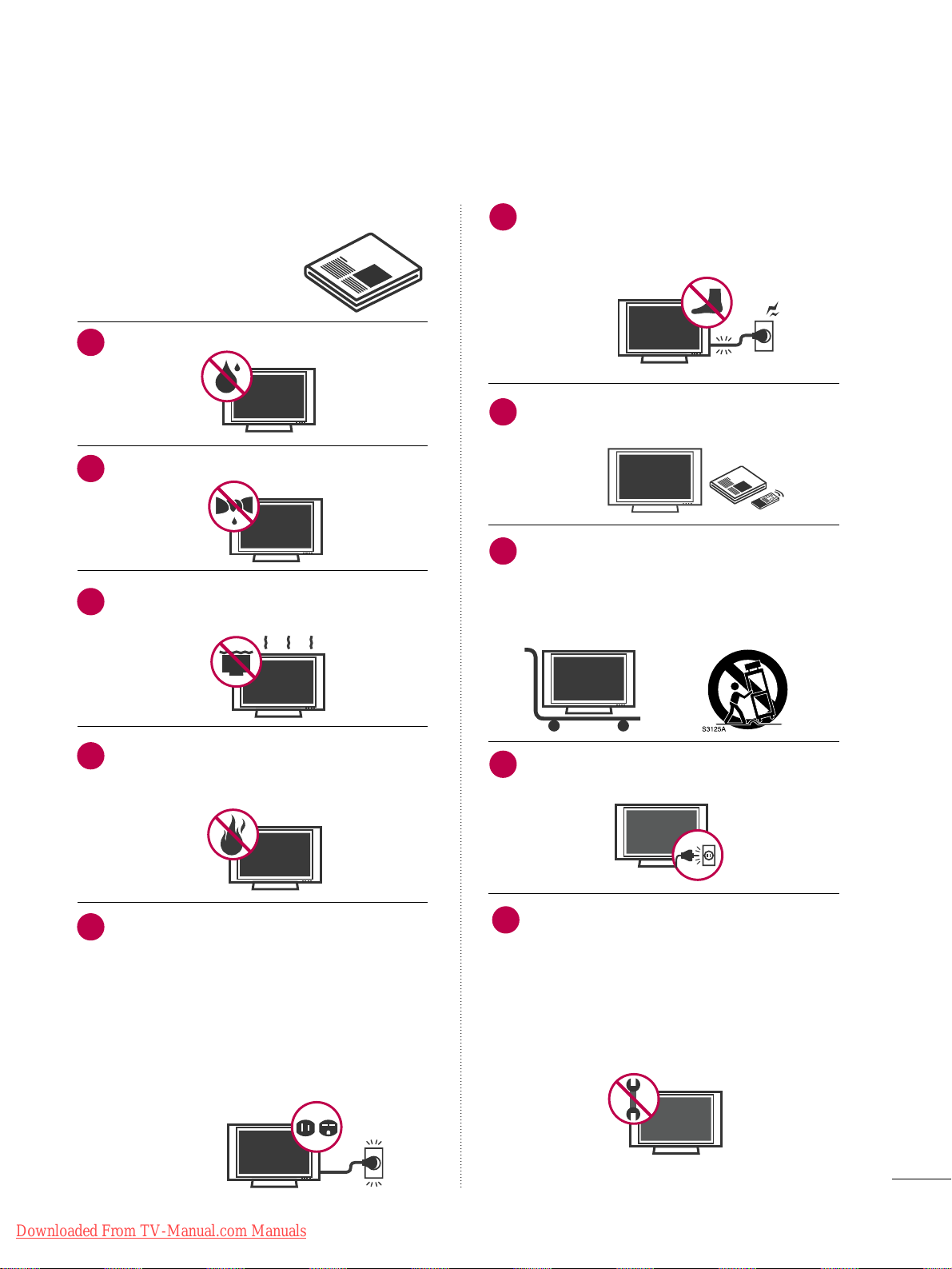
Do not use this apparatus near water.
Clean only with soft dry cloth.
Do not block any ventilation openings. Install in
accordance with the manufacturer’s instructions.
Do not install near any heat sources such as
radiators, heat registers, stoves, or other
apparatus (including amplifiers)that produce
heat.
Do not defeat the safety purpose of the polarized
or grounding-type plug. A polarized plug has
two blades with one wider than the other. A
grounding type plug has two blades and a
third grounding prong, The wide blade or the
third prong are provided for your safety. If the
provided plug does not fit into your outlet,
consult an electrician for replacement of the
obsolete outlet. (Can differ by country)
Protect the power cord from being walked on
or pinched particularly at plugs, convenience
receptacles, and the point where they exit from
the apparatus.
Only use attachments/accessories specified by
the manufacturer.
Use only with the cart, stand, tripod, bracket,
or table specified by the manufacturer, or sold
with the apparatus. When a cart is used, use
caution when moving the cart/apparatus combination to avoid injury from tip-over.
Unplug this apparatus during lighting storms
or when unused for long periods of time.
Refer all servicing to qualified service personnel.
Servicing is required when the apparatus has
been damaged in any way, such as powersupply cord or plug is damaged, liquid has
been spilled or objects have fallen into the
apparatus, the apparatus has been exposed to
rain or moisture, does not operate normally, or
has been dropped.
1
2
3
4
5
7
8
6
9
10
Downloaded From TV-Manual.com Manuals
4
SAFETY INSTRUCTIONS
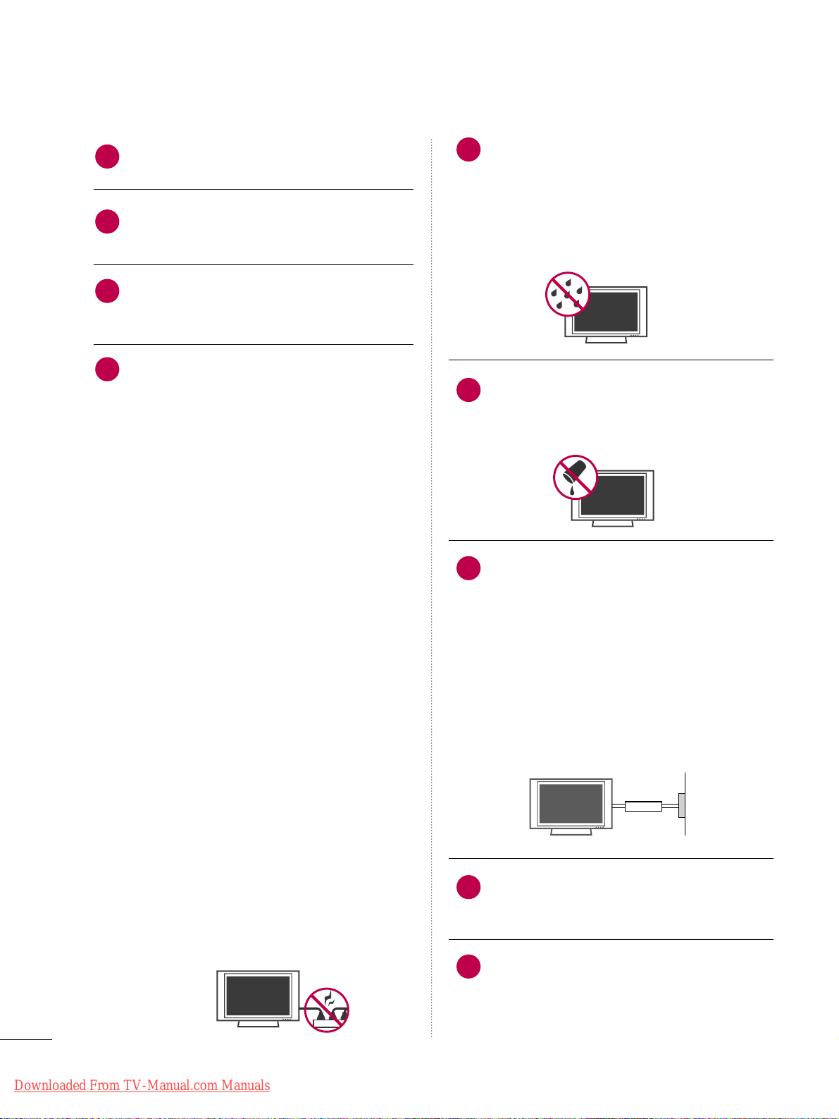
Never touch this apparatus or antenna during
a thunder or lighting storm.
When mounting a TV on the wall, make sure
not to install the TV by the hanging power and
signal cables on the back of the TV.
Do not allow an impact shock or any objects to
fall into the product, and do not drop onto the
screen with something.
CAUTION concerning the Power Cord:
It is recommend that appliances be placed
upon a dedicated circuit; that is, a single
outlet circuit which powers only that appliance
and has no additional outlets or branch
circuits. Check the specification page of this
owner's manual to be certain.
Do not connect too many appliances to the
same AC power outlet as this could result in
fire or electric shock.
Do not overload wall outlets. Overloaded wall
outlets, loose or damaged wall outlets, extension
cords, frayed power cords, or damaged or
cracked wire insulation are dangerous. Any of
these conditions could result in electric shock
or fire. Periodically examine the cord of your
appliance, and if its appearance indicates damage
or deterioration, unplug it, discontinue use of
the appliance, and have the cord replaced with
an exact replacement part by an authorized
servicer. Protect the power cord from physical
or mechanical abuse, such as being twisted,
kinked, pinched, closed in a door, or walked
upon. Pay particular attention to plugs, wall
outlets, and the point where the cord exits the
appliance.
Do not make the TV with the power cord
plugged in. Do not use a damaged or loose
power cord. Be sure do grasp the plug when
unplugging the power cord. Do not pull on the
power cord to unplug the TV.
WARNING - To reduce the risk of fire or electrical
shock, do not expose this product to rain,
moisture or other liquids. Do not touch the TV
with wet hands. Do not install this product
near flammable objects such as gasoline or
candles or expose the TV to direct air
conditioning.
Do not expose to dripping or splashing and do
not place objects filled with liquids, such as
vases, cups, etc. on or over the apparatus (e.g.
on shelves above the unit).
GGRROOUUNNDDIINNGG
Ensure that you connect the earth ground wire
to prevent possible electric shock (i.e. a TV
with a three-prong grounded AC plug must be
connected to a three-prong grounded AC outlet). If grounding methods are not possible,
have a qualified electrician install a separate
circuit breaker.
Do not try to ground the unit by connecting it
to telephone wires, lightening rods, or gas
pipes.
DDIISSCCOONNNNEECCTTIINNGG DDEEVVIICCEE FFRROOMM MMAAIINNSS
Mains plug is the disconnecting device. The
plug must remain readily operable.
"As long as this unit is connected to the AC wall
outlet, it is not disconnected from the AC power
source even if you turn off this unit by SWITCH"
12
11
14
13
16
17
18
19
Power
Supply
Short-circuit
Breaker
15
Downloaded From TV-Manual.com Manuals
5
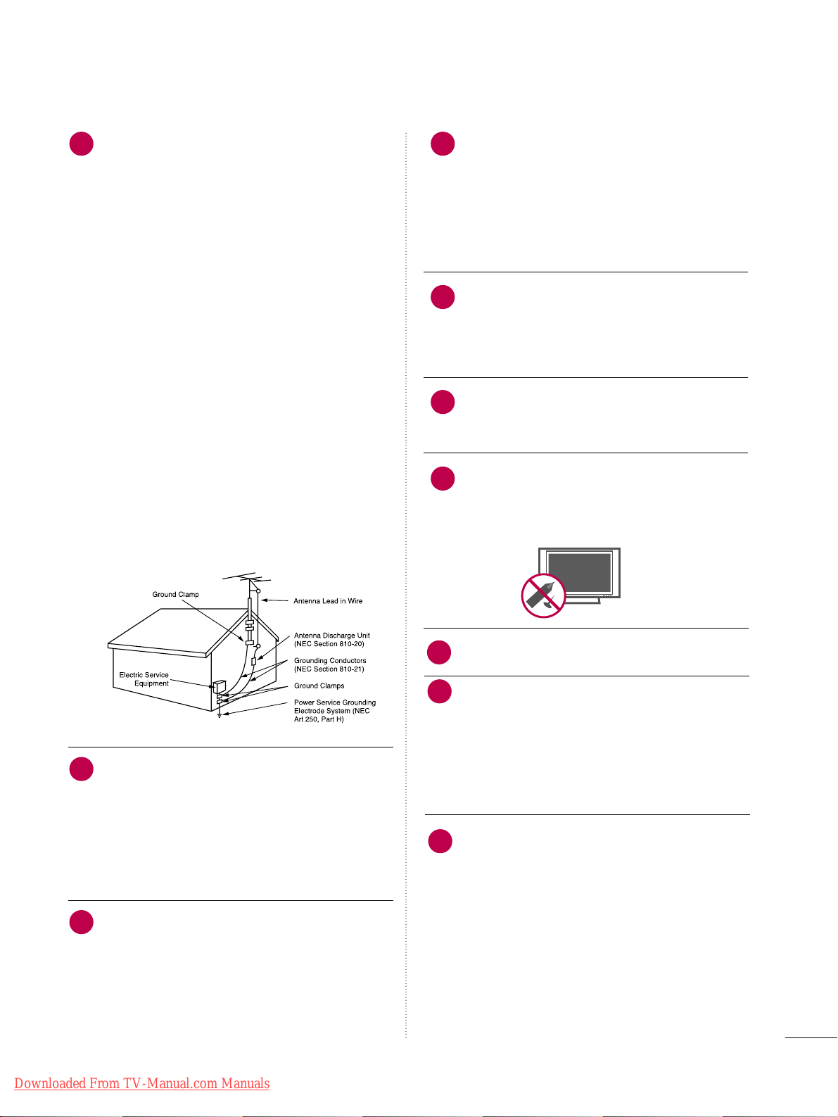
AANN TTEENNNNAASS
OOuuttddoooorr aanntt eennnnaa ggrroouunnddiinngg
(can differ by country) If an outdoor antenna
is installed, follow the precautions below. An
outdoor antenna system should not be located
in the vicinity of overhead power lines or other
electric light or power circuits, or where it can
come in contact with such power lines or circuits as death or serious injury can occur.
Be sure the antenna system is grounded so as
to provide some protection against voltage
surges and built-up static charges.
Section 810 of the National Electrical Code
(NEC) in the U.S.A. provides information with
respect to proper grounding of the mast and
supporting structure, grounding of the lead-in
wire to an antenna discharge unit, size of
grounding conductors, location of antenna discharge unit, connection to grounding electrodes and requirements for the grounding
electrode.
AAnntteennnnaa ggrroouunnddiinngg aaccccoorrddiinngg ttoo tthhee
NNaattiioonnaall EElleeccttrriiccaall CCooddee,, AANNSSII//NNFFPPAA 7700
CCll eeaanniinngg
When cleaning, unplug the power cord and
scrub gently with a soft cloth to prevent
scratching. Do not spray water or other liquids
directly on the TV as electric shock may occur.
Do not clean with chemicals such as alcohol,
thinners or benzene.
MMoovviinngg
Make sure the product is turned off,
unplugged and all cables have been removed. It
may take 2 or more people to carry larger TVs.
Do not press against or put stress on the front
panel of the TV.
VVeennttiillaattiioonn
Install your TV where there is proper ventila-
tion. Do not install in a confined space such as
a bookcase. Do not cover the product with
cloth or other materials (e.g.) plastic while
plugged in. Do not install in excessively dusty
places.
Take care not to touch the ventilation openings. When watching the TV for a long period,
the ventilation openings may become hot. This
does not affect the performance of the product
or cause defects in the proudct.
If you smell smoke or other odors coming from
the TV or hear strange sounds, unplug the power
cord contact an authorized service center.
Do not press strongly upon the panel with
hand or sharp object such as nail, pencil or
pen, or make a scratch on it. Do not allow a
impact shock onto the panel.
Keep the product away from direct sunlight.
DDoott DD eeffeecctt
The Plasma or LCD panel is a high technology
product with resolution of two million to six
million pixels. In a very few cases, you could see
fine dots on the screen while you’reviewing the
TV. Those dots are deactivated pixels and do
not affect the performance and reliability of the
TV.
GGeenneerraatteedd SSoouunndd
“Cracking” noise: A cracking noise that occurs
when watching or turning off the TV is generated by plastic thermal contraction due to
temperature and humidity. This noise is common for products where thermal deformation
is required.
Electrical circuit humming/panel buzzing: A low
level noise is generated from a high-speed
switching circuit, which supplies a large
amount of current to operate a product. It
varies depending on the product.This generated sound does not affect the performance and
reliability of the product.
20
23
24
25
26
21
22
27
NEC: National Electrical Code
28
29
Downloaded From TV-Manual.com Manuals

6
CONTENTS
WARNING / CAUTION
. . . . . . . . . . . . . . . . . . . . . . . . . . . . 2
SAFETY INSTRUCTIONS
. . . . . . . . . . . . . . . . . . . . . . . . . . 3
FEATURE OF THIS TV
. . . . . . . . . . . . . . . . . . . . . . . . . . . . . . . 8
PREPARATION
Accessories
. . . . . . . . . . . . . . . . . . . . . . . . . . . . . . . . . . . . . . . . . . . . . . . . . . . . . . 9
Front Panel Information . . . . . . . . . . . . . . . . . . . . . . . . . . . . . . . . . . .10
Back Panel Information . . . . . . . . . . . . . . . . . . . . . . . . . . . . . . . . . . . . . 11
Stand Instruction
. . . . . . . . . . . . . . . . . . . . . . . . . . . . . . . . . . . . . . . . . . . . . 13
Cable Management . . . . . . . . . . . . . . . . . . . . . . . . . . . . . . . . . . . . . . . . .
15
Desktop Pedestal Installation
. . . . . . . . . . . . . . . . . . . . . . . . . . . . 16
Swivel Stand
. . . . . . . . . . . . . . . . . . . . . . . . . . . . . . . . . . . . . . . . . . . . . . . . . . . . 16
VESA Wall Mounting
. . . . . . . . . . . . . . . . . . . . . . . . . . . . . . . . . . . . . . . . 17
Securing the TV to the wall to prevent falling
when the TV is used on a stand . . . . . . . . . . . . . . . . . . . . . . . .18
Antenna or Cable Connection
. . . . . . . . . . . . . . . . . . . . . . . . . . 19
EXTERNAL EQUIPMENT SETUP
HD Receiver Setup . . . . . . . . . . . . . . . . . . . . . . . . . . . . . . . . . . . . . . . . . 20
DVD Setup . . . . . . . . . . . . . . . . . . . . . . . . . . . . . . . . . . . . . . . . . . . . . . . . . . . . . 23
VCR Setup
. . . . . . . . . . . . . . . . . . . . . . . . . . . . . . . . . . . . . . . . . . . . . . . . . . . . . 25
Other A/V Source Setup . . . . . . . . . . . . . . . . . . . . . . . . . . . . . . . . .26
USB Connection
. . . . . . . . . . . . . . . . . . . . . . . . . . . . . . . . . . . . . . . . . . . . . 26
Audio Out Connection
. . . . . . . . . . . . . . . . . . . . . . . . . . . . . . . . . . . 27
PC Setup
. . . . . . . . . . . . . . . . . . . . . . . . . . . . . . . . . . . . . . . . . . . . . . . . . . . . . . . . 28
WATCHING TV / CHANNEL CONTROL
Remote Control Functions . . . . . . . . . . . . . . . . . . . . . . . . . . . . . . . 34
Turning On TV
. . . . . . . . . . . . . . . . . . . . . . . . . . . . . . . . . . . . . . . . . . . . . . . . 36
Channel Selection
. . . . . . . . . . . . . . . . . . . . . . . . . . . . . . . . . . . . . . . . . . .
36
Volume Adjustment
. . . . . . . . . . . . . . . . . . . . . . . . . . . . . . . . . . . . . . . . . 36
Initial Setting . . . . . . . . . . . . . . . . . . . . . . . . . . . . . . . . . . . . . . . . . . . . . . . . . . 37
On-Screen Menus Selection . . . . . . . . . . . . . . . . . . . . . . . . . . . . .38
Quick Menu
. . . . . . . . . . . . . . . . . . . . . . . . . . . . . . . . . . . . . . . . . . . . . . . . . . . 39
Channel Setup
- Auto Scan (Auto Tuning)
. . . . . . . . . . . . . . . . . . . . . . . . . . .40
- Add / Delete Channel (Manual Tuning)
. . . . . . 41
- Channel Editing . . . . . . . . . . . . . . . . . . . . . . . . . . . . . . . . . . . . . . . .
42
Channel List
. . . . . . . . . . . . . . . . . . . . . . . . . . . . . . . . . . . . . . . . . . . . . . . . . . . . 43
Favorite Channel Setup
. . . . . . . . . . . . . . . . . . . . . . . . . . . . . . . . . . . . 44
Favorite Channel List
. . . . . . . . . . . . . . . . . . . . . . . . . . . . . . . . . . . . . . .45
Brief Information
. . . . . . . . . . . . . . . . . . . . . . . . . . . . . . . . . . . . . . . . . . . . . 46
Input List . . . . . . . . . . . . . . . . . . . . . . . . . . . . . . . . . . . . . . . . . . . . . . . . . . . . . . . . 47
Input Label
. . . . . . . . . . . . . . . . . . . . . . . . . . . . . . . . . . . . . . . . . . . . . . . . . . . . . 48
AV Mode
. . . . . . . . . . . . . . . . . . . . . . . . . . . . . . . . . . . . . . . . . . . . . . . . . . . . . . . . 49
SIMPLINK
. . . . . . . . . . . . . . . . . . . . . . . . . . . . . . . . . . . . . . . . . . . . . . . . . . . . . . .50
USB
Entry Modes . . . . . . . . . . . . . . . . . . . . . . . . . . . . . . . . . . . . . . . . . . . . . . . . . . . 52
Photo List
. . . . . . . . . . . . . . . . . . . . . . . . . . . . . . . . . . . . . . . . . . . . . . . . . . . . . . .
53
Music List
. . . . . . . . . . . . . . . . . . . . . . . . . . . . . . . . . . . . . . . . . . . . . . . . . . . . . . .59
Movie List
. . . . . . . . . . . . . . . . . . . . . . . . . . . . . . . . . . . . . . . . . . . . . . . . . . . . . . .62
DivX Registration Code
. . . . . . . . . . . . . . . . . . . . . . . . . . . . . . . . . . . 68
Deactivation
. . . . . . . . . . . . . . . . . . . . . . . . . . . . . . . . . . . . . . . . . . . . . . . . . . . 69
PICTURE CONTROL
Picture Size (Aspect Ratio) Control . . . . . . . . . . . . . . . . . . 70
Picture Wizard
. . . . . . . . . . . . . . . . . . . . . . . . . . . . . . . . . . . . . . . . . . . . . . . . .72
Energy Saving
. . . . . . . . . . . . . . . . . . . . . . . . . . . . . . . . . . . . . . . . . . . .74
Preset Picture Settings(Picture Mode)
. . . . . . . . . . . . . . 75
Manual Picture Adjustment - User Mode
. . . . . . . . . . 76
Picture Improvement Technology
. . . . . . . . . . . . . . . . . . . . . 77
Expert Picture Control
. . . . . . . . . . . . . . . . . . . . . . . . . . . . . . . . . . . . . 78
Picture Reset
. . . . . . . . . . . . . . . . . . . . . . . . . . . . . . . . . . . . . . . . . . . . . . . . .80
Demo Mode
. . . . . . . . . . . . . . . . . . . . . . . . . . . . . . . . . . . . . . . . . . . . . . . . . .80
Image Sticking Minimization (ISM) Method
. . . . . . . 81
Downloaded From TV-Manual.com Manuals

7
SOUND & LANGUAGE CONTROL
Auto Volume Leveler (Auto Volume) . . . . . . . . . . . . . . . . . 82
Clear Voice II
. . . . . . . . . . . . . . . . . . . . . . . . . . . . . . . . . . . . . . . . . . . . . . . . . .83
Preset Sound Settings (Sound Mode)
. . . . . . . . . . . . . . 84
Sound Setting Adjustment - User Mode
. . . . . . . . . . .
85
Infinite Surround
. . . . . . . . . . . . . . . . . . . . . . . . . . . . . . . . . . . . . . . . . . . . . 86
Balance
. . . . . . . . . . . . . . . . . . . . . . . . . . . . . . . . . . . . . . . . . . . . . . . . . . . . . . . . . . 87
TV Speakers On/Off Setup
. . . . . . . . . . . . . . . . . . . . . . . . . . . . . . 88
Audio Reset
. . . . . . . . . . . . . . . . . . . . . . . . . . . . . . . . . . . . . . . . . . . . . . . . . . . . 89
Stereo/SAP Broadcast Setup
. . . . . . . . . . . . . . . . . . . . . . . . . . .90
Audio Language
. . . . . . . . . . . . . . . . . . . . . . . . . . . . . . . . . . . . . . . . . . . . . . 91
On-Screen Menus Language Selection
. . . . . . . . . . . . . 92
Caption Mode
- Analog Broadcasting System Captions
. . . . . . . 93
- Digital Broadcasting System Captions
. . . . . . . . 94
- Caption Option
. . . . . . . . . . . . . . . . . . . . . . . . . . . . . . . . . . . . . . . . 95
TIME SETTING
Clock Setting
- Auto Clock Setup
. . . . . . . . . . . . . . . . . . . . . . . . . . . . . . . . . . . . .
96
- Manual Clock Setup
. . . . . . . . . . . . . . . . . . . . . . . . . . . . . . . . . . 97
Auto On/Off Time Setting
. . . . . . . . . . . . . . . . . . . . . . . . . . . . . . . 98
Sleep Timer Setting
. . . . . . . . . . . . . . . . . . . . . . . . . . . . . . . . . . . . . . . . . 99
PARENTAL CONTROL / RATINGS
Set Password & Lock System . . . . . . . . . . . . . . . . . . . . . . . . .10 0
Channel Blocking . . . . . . . . . . . . . . . . . . . . . . . . . . . . . . . . . . . . . . . . . . . 10 3
Movie & TV Rating
. . . . . . . . . . . . . . . . . . . . . . . . . . . . . . . . . . . . . . . . 10 4
Downloadable Rating . . . . . . . . . . . . . . . . . . . . . . . . . . . . . . . . . . . . . 10 9
External Input Blocking
. . . . . . . . . . . . . . . . . . . . . . . . . . . . . . . . . . . 110
Key lock
. . . . . . . . . . . . . . . . . . . . . . . . . . . . . . . . . . . . . . . . . . . . . . . . . . . . . . . . . 111
APPENDIX
Troubleshooting . . . . . . . . . . . . . . . . . . . . . . . . . . . . . . . . . . . . . . . . . . . . .112
Maintenance
. . . . . . . . . . . . . . . . . . . . . . . . . . . . . . . . . . . . . . . . . . . . . . . . . .114
Product Specifications
. . . . . . . . . . . . . . . . . . . . . . . . . . . . . . . . . . . . 114
IR Codes
. . . . . . . . . . . . . . . . . . . . . . . . . . . . . . . . . . . . . . . . . . . . . . . . . . . . . . . .116
External Control Through RS-232C
. . . . . . . . . . . . . . . . .118
Downloaded From TV-Manual.com Manuals
8
FEATURE OF THIS TV
■
When a fixed image (e.g. logos, screen menus, video game, and computer display) is displayed on the TV
for an extended period, it can become permanently imprinted on the screen. This phenomenon is known
as “image burn” or “burn-in.” Image burn is not covered under the manufacturer’s warranty.
■
In order to prevent image burn, avoid displaying a fixed image on your TV screen for a prolonged period
(2 or more hours for LCD, 1 or more hours for Plasma).
■
Image burn can also occur on the letterboxed
areas of your TV if you use the 4:3 aspect
ratio setting for an extended period.
IMPORTANT INFORMATION TO PREVENT “IMAGE BURN
/ BURN-IN” ON YOUR TV SCREEN
High-definition television. High-resolution digital
television broadcast and playback system composed
of roughly a million or more pixels, 16:9 aspect-ratio
screens, and AC3 digital audio. A subset of digital
television, HDTV formats include 1080i and 720p
resolutions.
HDMI, the HDMI logo and High-Definition Multimedia
Interface are trademarks or registered trademarks of
HDMI Licensing LLC."
■
This feature is not available for all models.
This TV contains the detailed calibrations necessary
for professional certification by the Imaging Science
Foundation. The resulting ISF “day” and “night” modes
will then be accessible by the user to experience the
best their LG HDTV has to offer.
Sophisticated and detailed calibrations can be made
through the ISFccc mode.
Detailed calibration requires a licensed technician.
Please contact your local dealer to inquire about an
ISF certified technician.
AV Mode is three preset picture and audio settings. It
allows the viewer to quickly switch between common
settings. It includes Cinema, Sports, and Game Modes.
Displays HDTV programs in full 1920 x 1080p resolu-
tion for a more detailed picture.
Automatically enhances and amplifies the sound of
human voice frequency range to help keep dialogue
audible when background noise swells.
Unlike other sensors which can only sense brightness
of ambient light, LG’s “Intelligent Sensor” uses 4,096
sensing steps to evaluate its surroundings. Using a
sophisticated algorithm, the LG processes picture
quality elements including brightness, contrast, color,
sharpness and white balance. The result is a picture
optimized for it’s surroundings, more pleasing to
watch and which can also savne up to 50% in power
consumption.
View videos and photos and listen to music on your
TV through USB 2.0 (‘videos’ dependent on model).
ABOUT DIVX VIDEO: DivX® is a digital video format created by DivX, Inc. This is an official DivX
Certified® device that plays DivX video. Visit
www.divx.com for more information and software
tools to convert your files into DivX video.
ABOUT DIVX VIDEO-ON-DEMAND: This DivX
Certified® device must be registered in order to
play purchased DivX Video-on-Demand (VOD)
movies. To obtain your registration code, locate the
DivX VOD section in your device setup menu. Go to
vod.divx.com for more information on how to complete your registration.
“DivX Certified® to play DivX® video, including
premium content”
DivX®, DivX Certified® and associated logos are
trademarks of DivX, Inc. and are used under license.
Covered by one or more of the following U.S.
patents :
7,295,673; 7,460,668; 7,515,710; 7,519,274
Manufactured under license from Dolby Laboratories.
“
Dolby
“and the double-D symbol are trademarks of
Dolby Laboratories.
Downloaded From TV-Manual.com Manuals
PREPARATION
9
PREPARATION
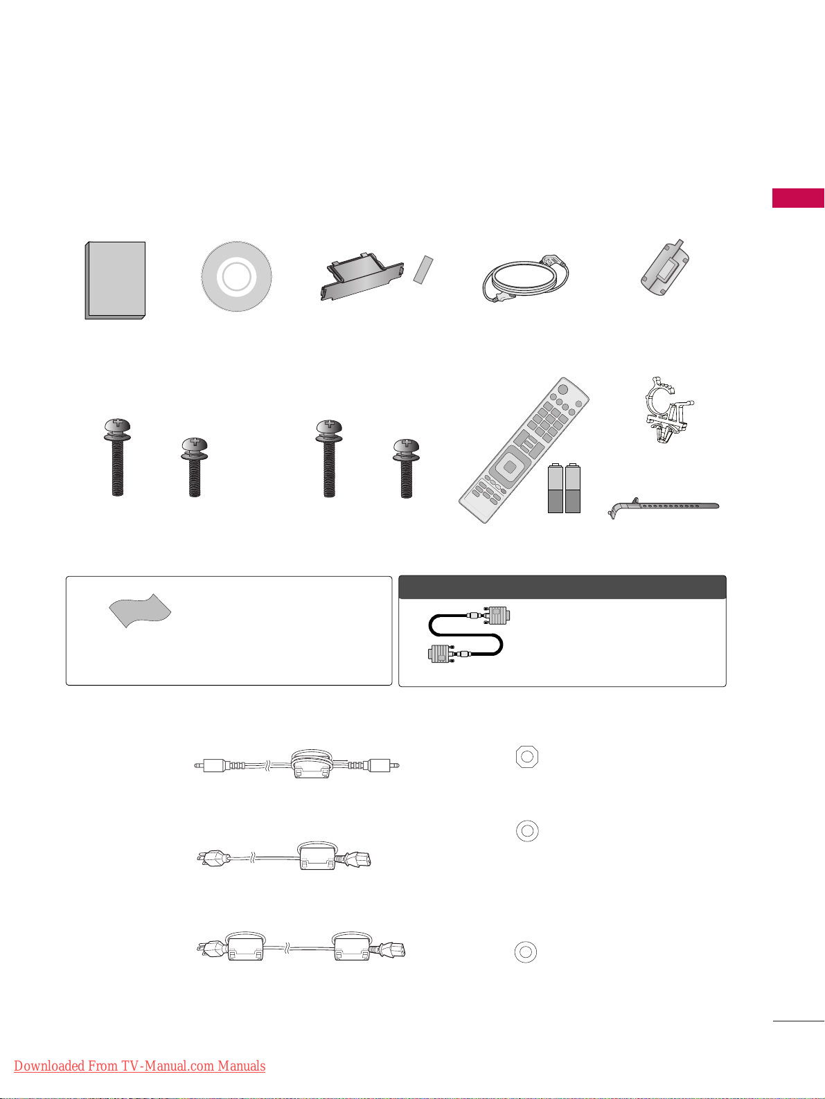
ACCESSORIES
Ensure that the following accessories are included with your TV. If an accessory is missing, please contact the
dealer where you purchased the TV.
The accessories included may differ from the images below.
Protection Cover and Tape
(Refer to P.14)
1.5V 1.5V
Owner’s Manual
Power Cord
Remote Control,
Batteries (AAA)
CD Manual
Screws for stand assembly
(Refer to P.13, 14)
x 4
OOppttiioonn EExxttrraass
* Wipe spots on the exterior only with
the polishing cloth.
* Do not wipe roughly when removing
spots. Excessive pressure may cause
scratch or discoloration.
Polishing Cloth
(Not included with all models)
D-sub 15 pin Cable
When using the VGA (D-sub 15 pin cable)
PC connection, the user must use shielded
signal interface cables with ferrite cores to
maintain standards compliance.
x 3
M4x26
M5x14.5
Screws for stand assembly
(Refer to P.13, 14)
x 4
x 3
M4x28
M5x24
Cable Holder
Power Cord Holder
(For 42/50PT200, 42/50PT330, 42/50PT350,
42/50PT350C, 42/50PT250U, 50PV400,
50PV430, 50PV450, 50PV450C, 50PV550U)
(For 60PV400, 60PV430, 60PV450,
60PV450C, 60PV550U)
Ferrite Core
(Depending on model)
■
How to use the Ferrite Core
1. Use the ferrite core to reduce the electromagnetic interference in the PC audio cable.
Wind the PC audio cable on the ferrite core thrice. Place the ferrite core close to the TV.
2. Use the ferrite core to reduce the electromagnetic interference in the power cable.
Wind the power cable on the ferrite core once. Place the ferrite core close to the TV.
3. Use the ferrite core to reduce the electromagnetic interference in the power cable.
Wind the power cable on the ferrite core once. Place the ferrite core close to the TV and a wall plug.
- If there is one ferrite core, follow as shown in Figure 1.
- If there are two ferrite cores, follow as shown in Figures 1 and 2.
- If there are three ferrite cores, follow as shown in Figures 1 and 3.
[to an External device]
[Figure 1]
[to the TV]
[to a wall plug]
[Figure 2]
[to the TV]
[to a wall plug]
[Figure 3]
[to the TV]
[Cross Section of
Ferrite Core]
[Cross Section of
Ferrite Core]
[Cross Section of
Ferrite Core]
10 mm (+/-5 mm)
Downloaded From TV-Manual.com Manuals
PREPARATION
10
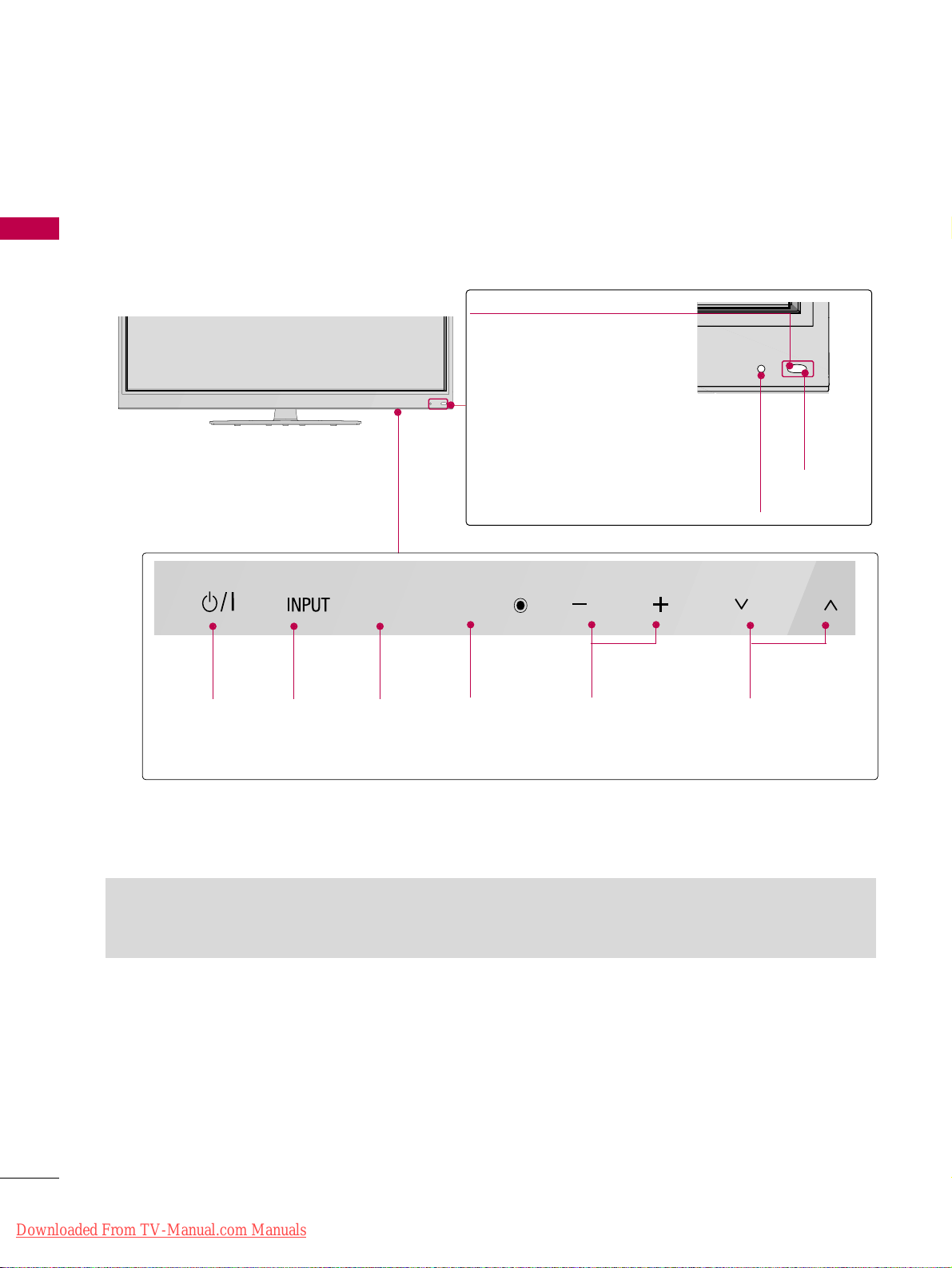
FRONT PANEL INFORMATION
PREPARATION
■
Image shown may differ from your TV.
CH
VOL
ENTER
HOME
POWER
Button
INPUT
Button
HOME
Button
ENTER
Button
VOLUME
Buttons
Power/Standby Indicator
Illuminates red in standby mode.
The LED is off while the TV
remains on.
Intelligent Sensor
Adjusts picture according to
the surrounding conditions.
CHANNEL
Buttons
Remote
Control
Sensor
You can operate the buttons just by touching them lightly with your finger.
GG
Do not step on the glass stand or subject it to any impact. It may break, causing possible injury from fragments of
glass, or the TV may fall.
GG
Do not drag the TV. The floor or the product may be damaged.
Downloaded From TV-Manual.com Manuals
PREPARATION
11
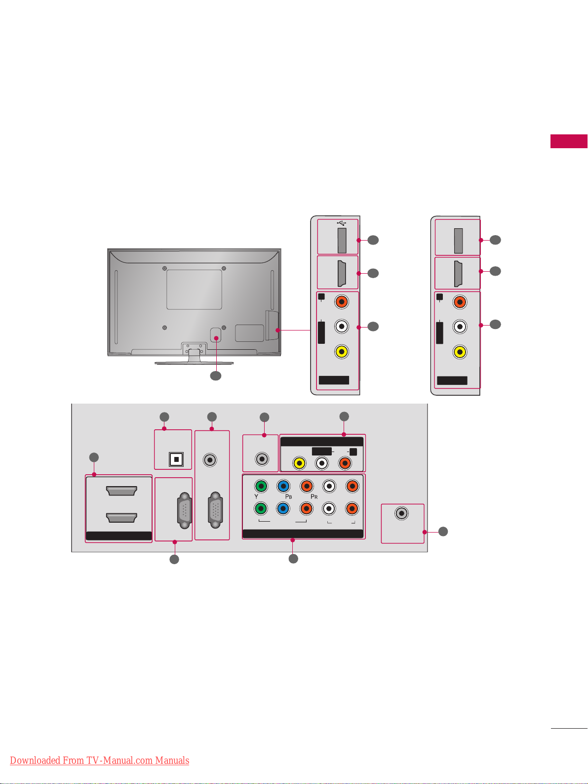
■
Image shown may differ from your TV.
BACK PANEL INFORMATION
AV IN 2
L/ MONO
R
AUDIO
VIDEO
USB IN
HDMI IN 3
7
1
9
R
ANTENNA
/CABLE
IN
HDMI/DVI IN
2
1
RGB IN (PC)
RS-232C IN
(CONTROL & SERVICE)
OPTICAL
DIGITAL
AUDIO OUT
AUDIO IN
(RGB/DVI)
COMPONENT IN
1
2
VIDEO
AUDIO
L
R
REMOTE
CONTROL IN
AV IN 1
AUDIO
VIDEO
/MONO
L/ MONO
R
1
2
3
4
5
7
8
11
6
10
(For 42/50PT250U, 42/50PT350,
42/50PT350C, 50/60PV450,
50/60PV450C, 50/60PV550U)
(For 42/50PT200, 42/50PT330,
50/60PV400, 50/60PV430)
7
1
ONLY
SERVICE
HDMI IN 3
R
AUDIO
L/MONO
VIDEO
AV IN 2
Downloaded From TV-Manual.com Manuals
PREPARATION
12
PREPARATION
HDMI/DVI IN
Digital Connection. Supports HD video and
Digital audio. Doesn’t support 480i.
Accepts DVI video using an adapter or HDMI to
DVI cable (not included)
OPTICAL DIGITAL AUDIO OUT
Optical digital audio output for use with amps and
home theater systems.
Note: In standby mode, this port doesn’t work.
RS-232C IN (CONTROL & SERVICE) PORT
Used by third party devices.
AUDIO IN (RGB/DVI)
1/8” headphone jack for analog PC audio input.
RGB IN (PC)
Analog PC Connection. Uses a D-sub 15 pin cable
(VGA cable).
REMOTE CONTROL IN PORT
For a wired remote control.
COMPONENT IN
Analog Connection. Supports HD.
Uses a red, green, and blue cable for video & red
and white for audio.
AV (Audio/Video) IN
Analog composite connection. Supports standard
definition video only (480i).
ANTENNA/CABLE IN
Connect over-the air signals to this jack.
Connect cable signals to this jack.
USB IN
Used for viewing photos, waching movies and listening to MP3s.
SERVICE ONLY
Used for software updates.
Power Cord Socket
For operation with AC power.
Caution: Never attempt to operate the TV on DC
power.
1
2
3
4
5
9
10
8
6
7
11
Downloaded From TV-Manual.com Manuals
PREPARATION
13
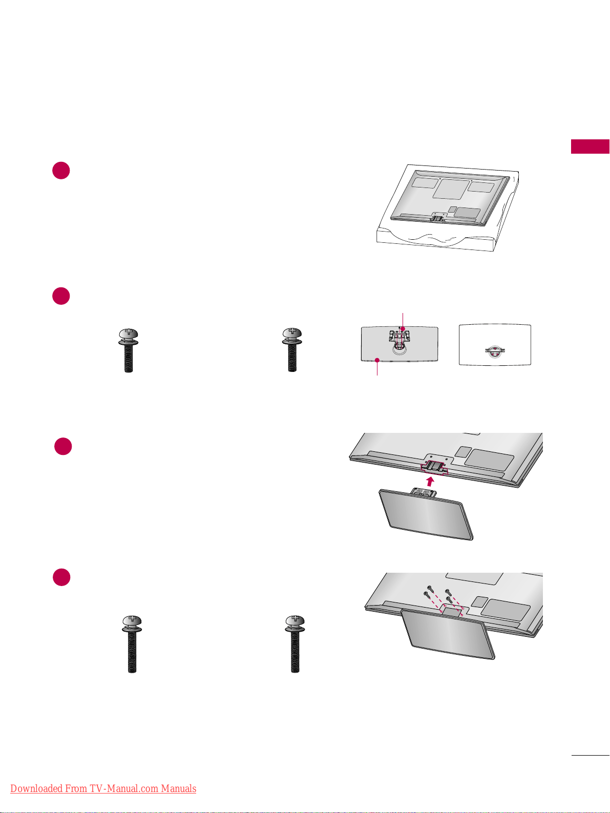
STAND INSTRUCTION
■
Image shown may differ from your TV.
Carefully place the TV screen side down on a
cushioned surface to protect the screen from
damage.
Assemble the parts of the Stand Body with the
Stand Base of the TV.
1
2
Assemble the TV as shown.
3
Installation
Fix the 4 screws securely using the holes in the
back of the TV.
4
Stand Body
Stand Base
M4x26
M5x14.5
x 3
x 4
M4x28
x 4
M5x24
x 3
(For 42/50PT200, 42/50PT330, 42/50PT350,
42/50PT350C, 42/50PT250U, 50PV400,
50PV430, 50PV450, 50PV450C, 50PV550U)
(For 60PV400, 60PV430, 60PV450,
60PV450C, 60PV550U)
(For 42/50PT200, 42/50PT330, 42/50PT350,
42/50PT350C, 42/50PT250U, 50PV400,
50PV430, 50PV450, 50PV450C, 50PV550U)
(For 60PV400, 60PV430, 60PV450,
60PV450C, 60PV550U)
Downloaded From TV-Manual.com Manuals
PREPARATION
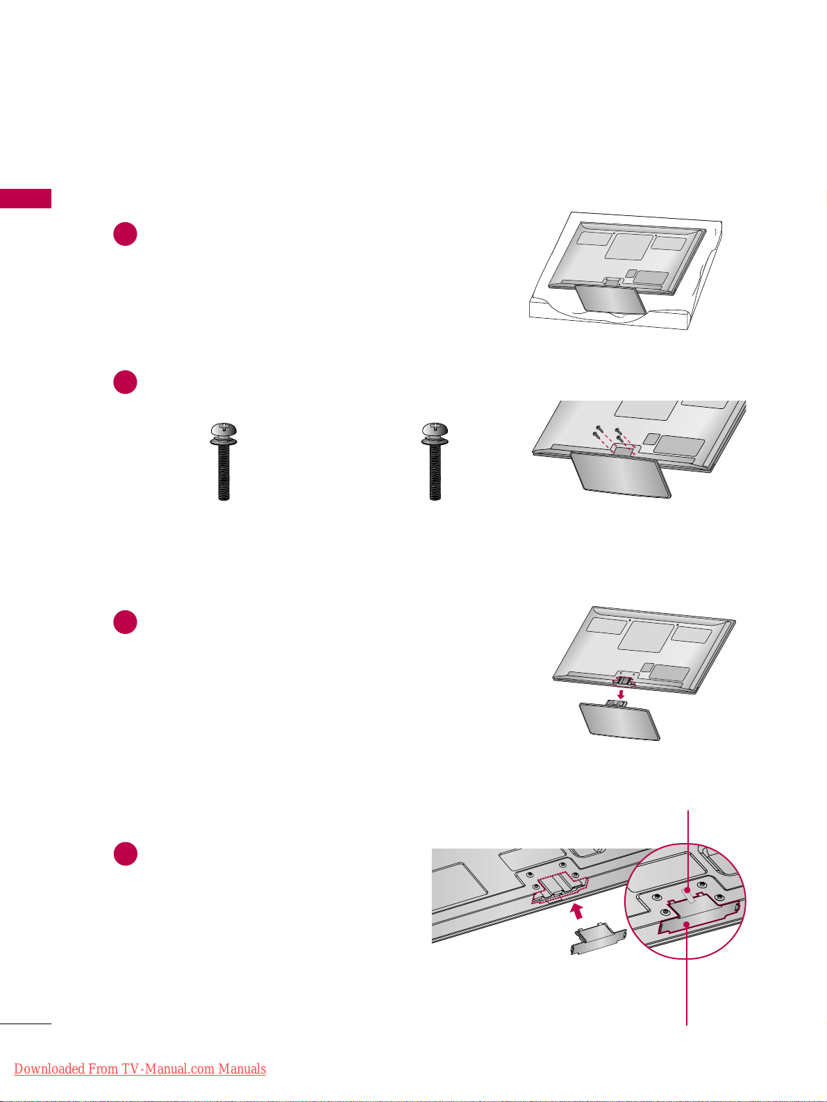
14
PREPARATION
Carefully place the TV screen side down on a
cushioned surface to protect the screen from
damage.
1
Loose the screws from TV.
2
Detach the stand from TV.
3
Detachment
Attach the protection
cover tape.
After removing the stand, install the included
PPRROOTTEECCTTIIOONN CCOOVVEERR
over the hole for
the stand.
Attach the protection cover tape.
When installing the wall mounting bracket, use
the
PPRROOTTEECCTTIIOONN CCOOVVEERR
.
PROTECTION COVER
Fix a Guide to the Outsides.
M4x26
x 4
M4x28
x 4
(For 42/50PT200, 42/50PT330, 42/50PT350,
42/50PT350C, 42/50PT250U, 50PV400,
50PV430, 50PV450, 50PV450C, 50PV550U)
(For 60PV400, 60PV430,
60PV450, 60PV450C, 60PV550U)
4
Downloaded From TV-Manual.com Manuals
PREPARATION
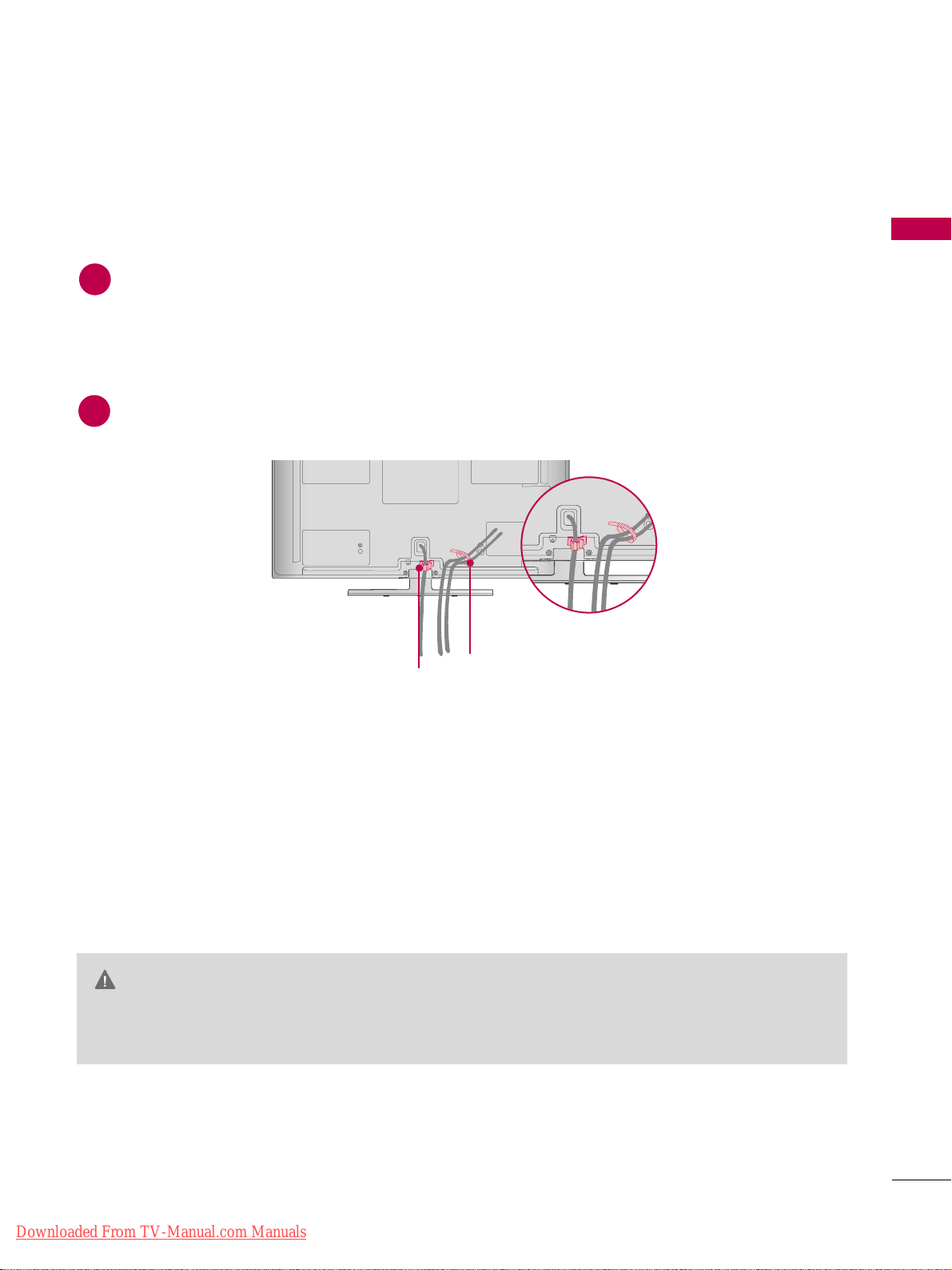
15
CABLE MANAGEMENT
Install the power cord holder and power cord.
It will help prevent the power cable from being removed by accident.
1
POWER CORD
HOLDER
■
Image shown may differ from your TV.
Gather and bind the cables with the cable holder.
2
CABLE HOLDER
GG
Do not move the TV by holding the cable holder and power cord holder, as the cable holders may
break, and injuries and damage to the TV may occur.
CAUTION
Downloaded From TV-Manual.com Manuals
PREPARATION
16
PREPARATION
DESKTOP PEDESTAL INSTALLATION
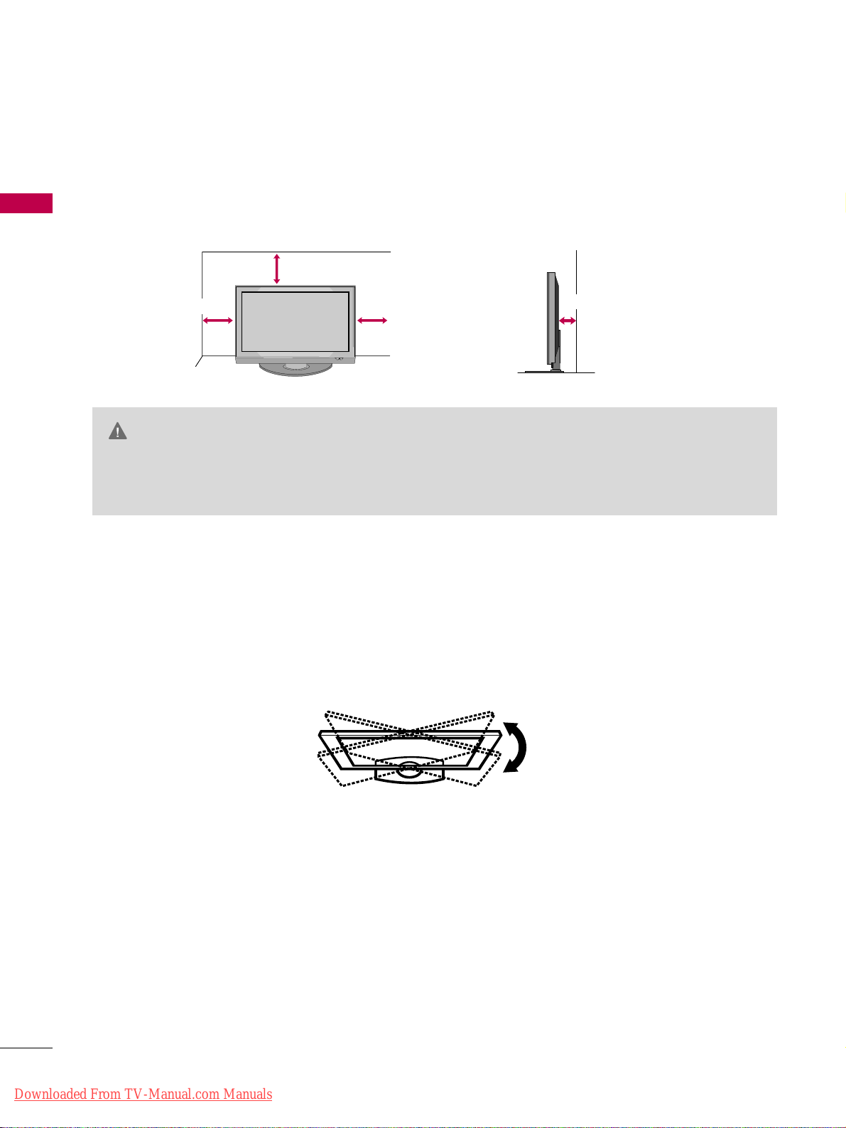
For proper ventilation, allow a clearance of 4 inches on all four sides from the wall.
■
Image shown may differ from your TV.
4 inches
4 inches
4 inches
4 inches
GG
Ensure adequate ventilation by following the clearance recommendations.
GG
Do not mount near or above any type of heat source.
CAUTION
SWIVEL STAND
■
This feature is not available for all models.
After installing the TV, you can adjust the TV manually to the left or right direction by 20 degrees to suit your
viewing position.
Downloaded From TV-Manual.com Manuals
PREPARATION
17
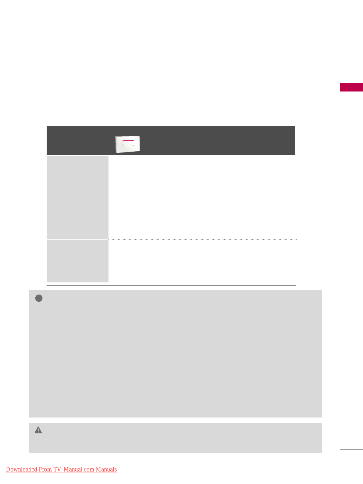
VESA WALL MOUNTING
Install your wall mount on a solid wall perpendicular to the floor. When attaching to other building materials, please
contact your nearest installer.
If installed on a ceiling or slanted wall, it may fall and result in severe personal injury.
We recommend that you use an LG brand wall mount when mounting the TV to a wall.
LG recommends that wall mounting be performed by a qualified professional installer.
GG
Do not install your wall mount kit while your TV is turned on. It may result in personal injury due to electric shock.
CAUTION
GG
Screw length needed depends on the wall mount
used. For further information, refer to the instructions included with the mount.
GG
Standard dimensions for wall mount kits are shown
in the table.
GG
When purchasing our wall mount kit, a detailed
installation manual and all parts necessary for
assembly are provided.
GG
Do not use screws longer then the standard dimension, as they may cause damage to the inside to
the TV.
GG
For wall mounts that do not comply with the VESA
standard screw specifications, the length of the
screws may differ depending on their specifications.
GG
Do not use screws that do not comply with the
VESA standard screw specifications.
Do not use fasten the screws too strongly, this may
damage the TV or cause the TV to a fall, leading to
personal injury. LG is not liable for these kinds of
accidents.
GG
LG is not liable for TV damage or personal injury
when a non-VESA or non specified wall mount is
used or the consumer fails to follow the TV installation instructions.
NOTE
!
Model
VESA (A *B)
Standard Screw Quantity
Wall Mounting
bracket
(sold separately)
42/50PT200,
42/50PT330,
42/50PT350,
42/50PT350C,
50PV400,
50PV430,
50PV450,
50PV450C,
42/50PT250U,
50PV550U
400* 400 M6 4
PSW400B,
PSW400BG,
DSW400BG
PSW600B,
PSW600BG
60PV400,
60PV430,
60PV450,
60PV450C,
60PV550U
600* 400 M8 4
AA
BB
Downloaded From TV-Manual.com Manuals
PREPARATION
18
PREPARATION
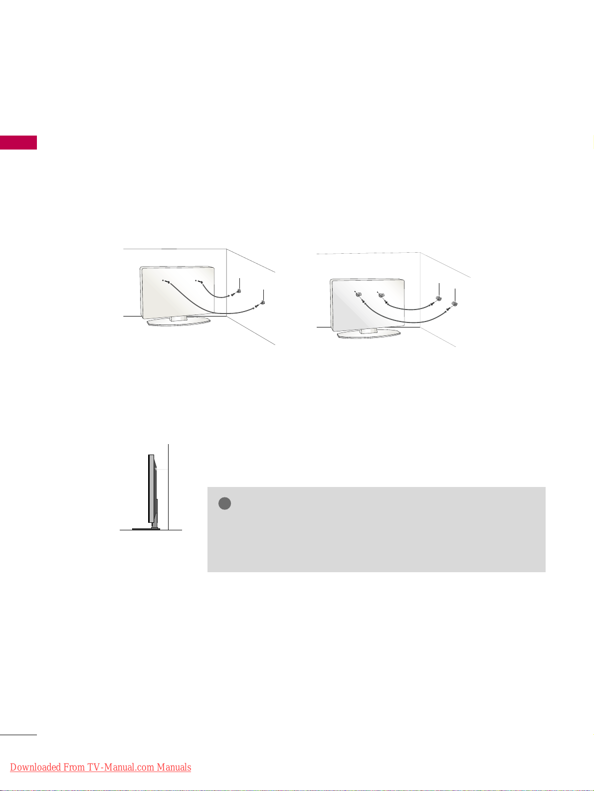
SECURING THE TV TO THE WALL TO PREVENT FALLING WHEN THE TV IS USED ON A STAND
We recommend that you set up the TV close to a wall so it cannot fall over if pushed backwards.
Additionally, we recommend that the TV be attached to a wall so it cannot be pulled in a forward direction,
potentially causing injury or damaging the product.
Caution: Please make sure that children don’t climb on or hang from the TV.
■
Insert the eye-bolts (or TV brackets and bolts) to tighten the product to the wall as shown in the picture.
*If your product has the bolts in the eye-bolts position before inserting the eye-bolts, loosen the bolts.
* Insert the eye-bolts or TV brackets/bolts and tighten them securely in the upper holes.
Secure the wall brackets with the bolts (sold separately) to the wall. Match the height of the bracket that is
mounted on the wall to the holes in the product.
Ensure the eye-bolts or brackets are tightened securely.
■
Use a sturdy rope (sold separately) to tie the product. It is safer to tie
the rope so it becomes horizontal between the wall and the product.
■
You should purchase necessary components to prevent the TV from tipping over (when not using a wall mount).
■
Image shown may differ from your TV.
GG
Use a platform or cabinet strong enough and large enough to support
the size and weight of the TV.
GG
To use the TV safely, make sure that the height of the bracket on the
wall and the one on the TV are the same.
NOTE
!
Downloaded From TV-Manual.com Manuals
PREPARATION
19
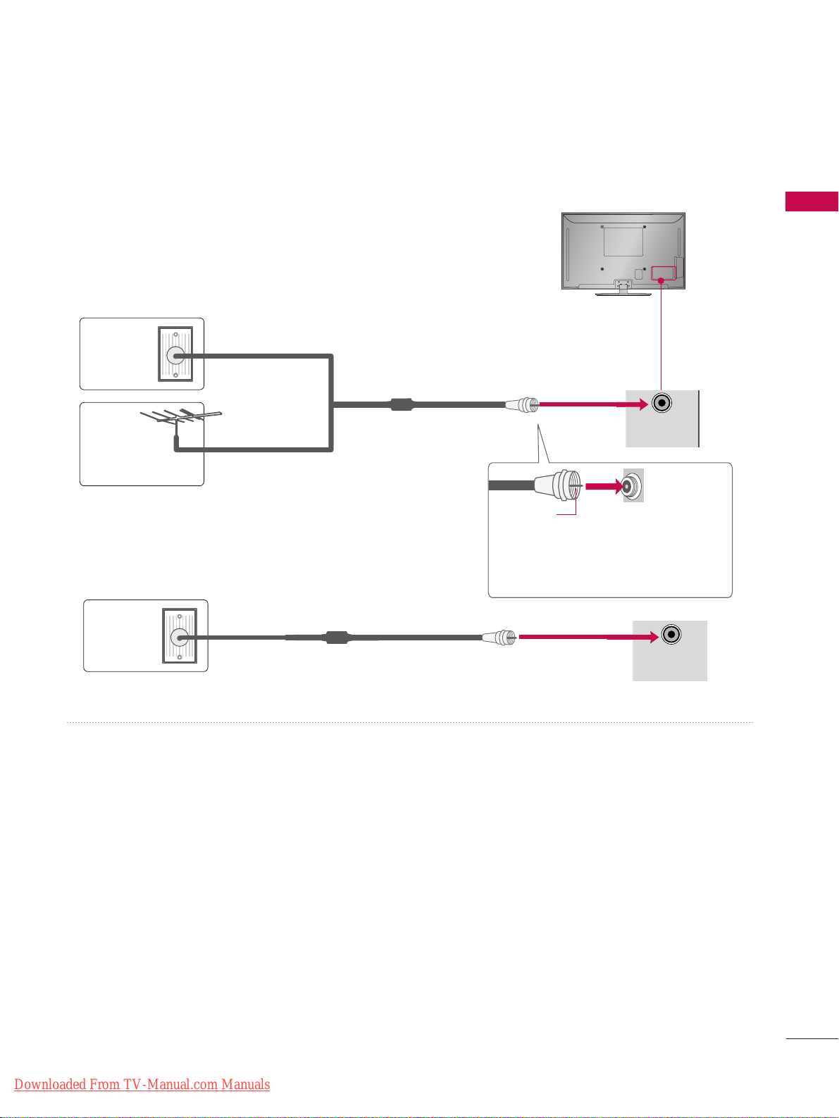
ANTENNA OR CABLE CONNECTION
1. Antenna (Analog or Digital)
Wall Antenna Socket or Outdoor Antenna without a Cable Box
Connection.
For optimum picture quality, adjust antenna direction if needed.
2. Cable
Cable TV
Wall Jack
RF Coaxial Wire (75 Ω)
■
To improve the picture quality in a poor signal area, please purchase a signal amplifier and install properly.
■
If the antenna needs to be split for two TV’s, install a 2-Way Signal Splitter.
■
If the antenna is not installed properly, contact your dealer for assistance.
■
To prevent damage do not connect to the power outlet until all connections are made between the devices.
Wall
Antenna
Socket
Outdoor
Antenna
(VHF, UHF)
Multi-family Dwellings/Apartments
(Connect to wall antenna socket)
RF Coaxial Wire (75
Ω)
Single-family Dwellings /Houses
(Connect to wall jack for outdoor antenna)
Be careful not to bend the copper wire
when connecting the antenna.
Copper Wire
R
ANTENNA
/CABLE
IN
R
ANTENNA
/CABLE
IN
Downloaded From TV-Manual.com Manuals
EXTERNAL EQUIPMENT SETUP
20
HD RECEIVER SETUP
This TV can receive Digital Over-the-air/Cable signals without an external digital set-top box. However, if you do
receive digital signals from a digital set-top box or other digital external device, refer to the figure as shown below.
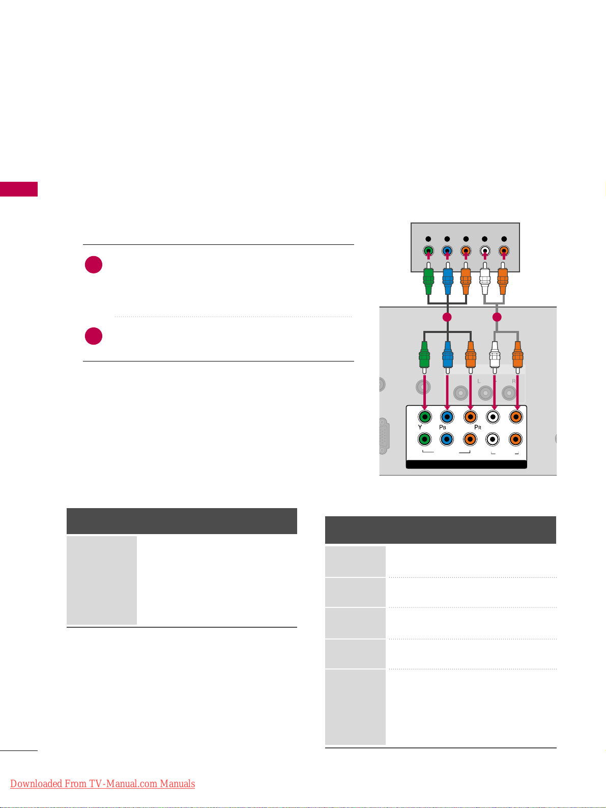
Component Connection
1. How to connect
Connect the video outputs (Y, PB, PR
)
of the digital set-
top box to the
CCOOMMPPOONNEENNTT IINN VVIIDDEEOO 11
jacks on
the TV. Match the jack colors (Y = green, P
B = blue, and
P
R = red).
Connect the audio output of the digital set-top box to
the
CCOOMMPPOONNEENNTT IINN AAUUDDIIOO 11
jacks on the TV.
2
1
2. How to use
■
Turn on the digital set-top box.
(
Refer to the owner’s manual for the digital set-top box. operation
)
■
Select the
CCoommpp oonn eenntt11
input source on the TV using the
IINNPPUU TT
button on the remote control.
■
If connected to
CCOOMMPPOONNEENNTT II NN 22
input, select the
CCoommpp oonn eenntt22
input source on the TV.
■
To prevent the equipment damage, never plug in any power cords until you have finished connecting all equipment.
■
Image shown may differ from your TV.
ANT
CA
O IN
REMOTE
CONTROL IN
AUDIO
VIDEO
/MONO
AV IN 1
COMPONENT IN
1
2
VIDEO
AUDIO
L
R
Y L RPB PR
1
2
Y, CB/PB, CR/PR
Supported Resolutions
Horizontal Vertical
Frequency(KHz)Frequency(Hz
)
15.73 59.94
15.73 60.00
31.47 59.94
31.47 60.00
44.96 59.94
45.00 60.00
33.72 59.94
33.75 60.00
27.00 24.00
33.75 30.00
67. 432 59.939
67.50 60.00
26.97 23.94
33.71 29.97
Resolution
720x480i
720x480p
1280x720p
1920x1080i
1920x1080p
Signal
480i
480p
720p
10 8 0 i
10 8 0 p
Component
Yes
Yes
Yes
Yes
Yes
HDMI
No
Yes
Yes
Yes
Yes
EXTERNAL EQUIPMENT SETUP
Downloaded From TV-Manual.com Manuals
EXTERNAL EQUIPMENT SETUP
21
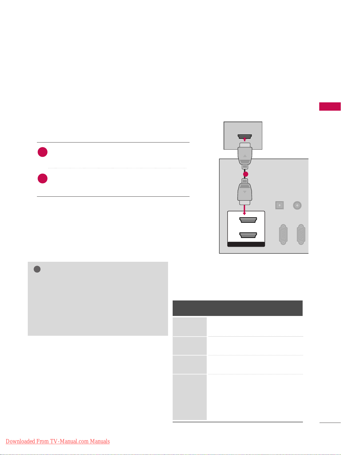
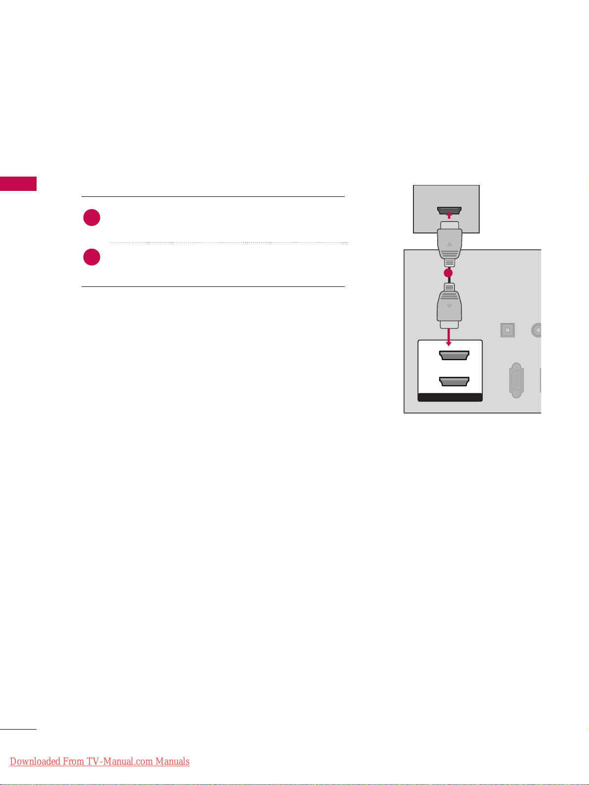
HDMI Connection
Connect the digital set-top box to
HHDDMMII// DDVVII IINN 11
,
22
, or
HHDDMMII IINN 33
jack on the TV.
No separate audio connection is necessary.
HDMI supports both audio and video.
1. How to connect
2. How to use
■
Turn on the digital set-top box.
(
Refer to the owner’s manual for the digital set-top box.
)
■
Select the
HHDDMMII11, 22
, or
33
input source on the TV using the
IINNPPUUTT
button on the remote control.
2
1
HDMI-DTV
Horizontal Vertical
Frequency(KHz)Frequency(Hz
)
31.47 59.94
31.47 60.00
44.96 59.94
45.00 60.00
33.72 59.94
33.75 60.00
27.00 24.00
33.75 30.00
67. 432 59.939
67.50 60.00
26.97 23.94
33.71 29.97
Resolution
720x480p
1280x720p
1920x1080i
1920x1080p
HDMI/DVI IN
2
1
HDMI-DTV OUTPUT
RGB IN(PC)
RS-232C IN
(CONTROL & SERVICE)
OPTICAL
DIGITAL
AUDIO OUT
AUDIO
(RGB/DVI)
1
GG
If an HDMI cable doesn’t support High Speed
HDMI, it can cause flickers or no screen display.
In this case use the latest cables that support High
Speed HDMI.
GG
HDMI mode supports PCM, AC-3(Dolby Digital)
audio format.
NOTE
!
Downloaded From TV-Manual.com Manuals
EXTERNAL EQUIPMENT SETUP
22
EXTERNAL EQUIPMENT SETUP
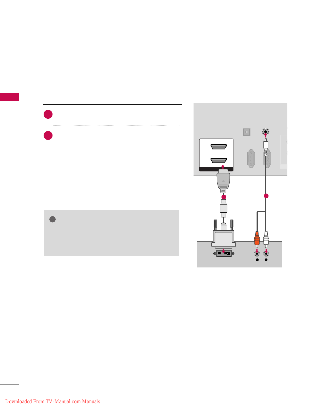
DVI to HDMI Connection
RGB IN (PC)
RS-232C IN
(CONTROL & SERVICE)
OPTICAL
DIGITAL
AUDIO OUT
AUDIO IN
(RGB/DVI)
HDMI/DVI IN
2
1
LR
DVI-DTV OUTPUT
R
CO
1
2
1
2
GG
A DVI to HDMI cable or adapter is required for this
connection. DVI doesn't support audio, so a separate
audio connection is necessary.
NOTE
!
Connect the DVI output of the digital set-top box to the
HHDDMMII//DDVVII IINN 11
or
22
jack on the TV.
Connect the audio output of the digital set-top box to
the
AAUUDDIIOO IINN ((RRGGBB//DDVVII))
jack on the TV.
1. How to connect
2. How to use
■
Turn on the digital set-top box. (Refer to the owner’s manual for the digital set-top box.
)
■
Select the
HHDDMMII11
or 22input source on the TV using the
IINN PPUUTT
button on the remote control.
2
1
Downloaded From TV-Manual.com Manuals
EXTERNAL EQUIPMENT SETUP
23
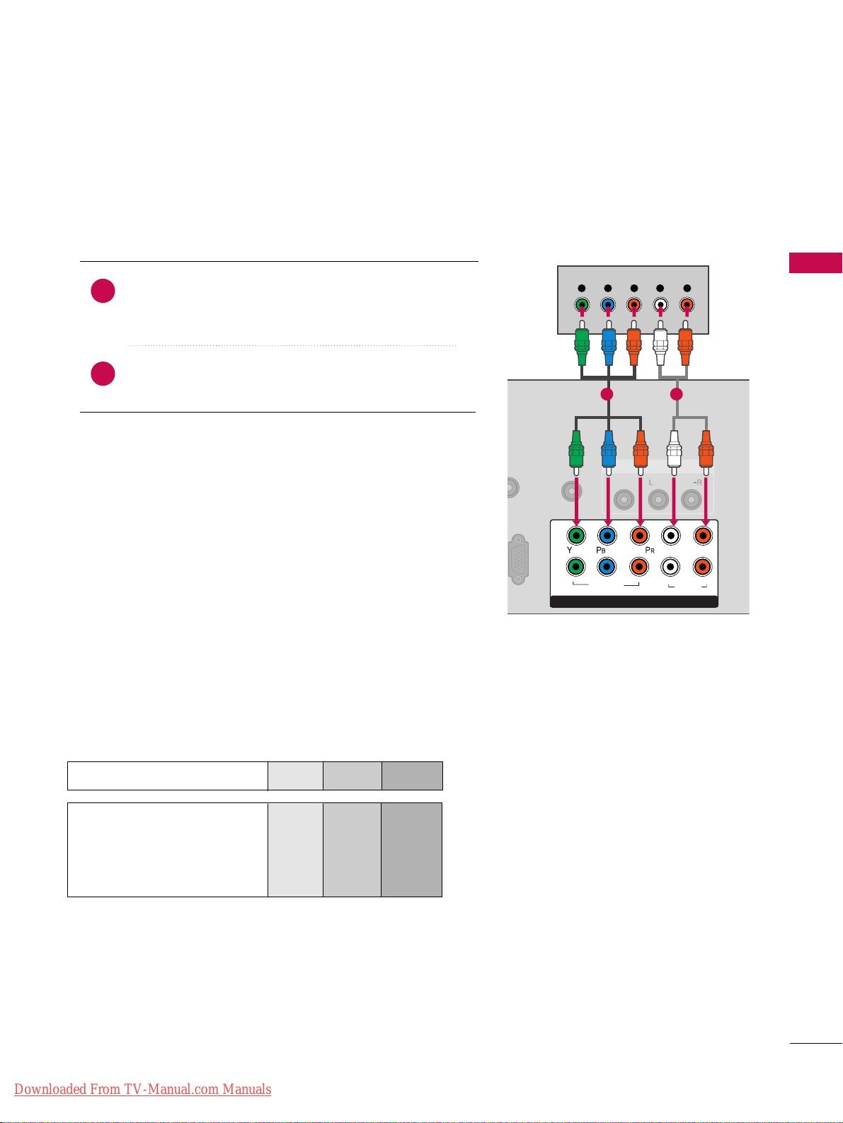
DVD SETUP
Component Connection
Component Input ports
To get better picture quality, connect a DVD player to the component input ports as shown below.
Component ports on the TV
YPBP
R
Video output ports
on DVD player
Y
Y
Y
Y
PB
B-Y
Cb
Pb
PR
R-Y
Cr
Pr
Connect the video outputs (Y, PB
, PR
)
of the DVD to the
CCOOMM PPOONNEENNTT IINN VVIIDDEEOO 11
jacks on the TV.
Match the jack colors (Y = green, P
B = blue, and PR = red
)
.
Connect the audio outputs of the DVD to the
CCOOMM PPOONNEENNTT IINN AAUUDDIIOO 11
jacks on the TV.
1. How to connect
2. How to use
■
Turn on the DVD player, insert a DVD.
■
Select the
CCoommpp oonneenn tt11
input source on the TV using
the
IINNPPUU TT
button on the remote control.
■
If connected to
CCOOMMPPOONNEENNTT II NN 22
input, select the
CCoommpp oonn eenntt22
input source on the TV.
■
Refer to the DVD player's manual for operating instructions.
2
1
A
REMOTE
CONTROL IN
AUDIO
VIDEO
/MONO
AV IN 1
COMPONENT IN
1
2
VIDEO
AUDIO
L
R
Y L RPB PR
1 2
Downloaded From TV-Manual.com Manuals
EXTERNAL EQUIPMENT SETUP
24
EXTERNAL EQUIPMENT SETUP
HDMI Connection
Connect the HDMI output of the DVD to the
HHDDMMII//DDVVII IINN 11, 22
, or
HHDDMMII IINN 33
jack on the TV.
No separate audio connection is necessary.
HDMI supports both audio and video.
1. How to connect
2. How to use
■
Select the
HHDDMMII11, 22
, or
33
input source on the TV using
the
IINNPPUU TT
button on the remote control.
■
Refer to the DVD player's manual for operating instructions.
2
1
HDMI/DVI IN
2
1
RGB IN (PC)
RS-232C IN
(CONTROL & SERVICE)
OPTICAL
DIGITAL
AUDIO OUT
AUD
(RGB/D
HDMI-DVD OUTPUT
1
Downloaded From TV-Manual.com Manuals
EXTERNAL EQUIPMENT SETUP
25
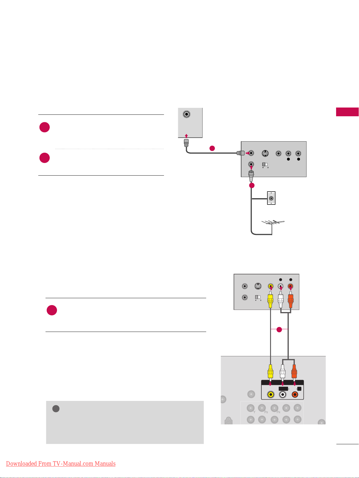
VCR SETUP
Antenna Connection
CABLE
IN
L R
S-VIDEO VIDEO
OUTPUT
SWITCH
ANT IN
ANT OUT
Wall Jack
Antenna
1
2
Connect the RF antenna out socket of the
VCR to the
AANNTTEENNNNAA//CCAABBLLEE IINN
socket
on the TV.
Connect the antenna cable to the RF
antenna in socket of the VCR.
1. How to connect
2. How to use
■
Set VCR output switch to 3 or 4 and then
tune TV to the same channel number.
■
Insert a video tape into the VCR and press
PLAY on the VCR. (Refer to the VCR owner’s
manual.
)
2
1
Composite (RCA) Connection
Connect the
AAUUDDIIOO/VVIIDDEEOO
jacks between TV and
VCR. Match the jack colors (Video = yellow, Audio Left
= white, and Audio Right = red)
1. How to connect
2. How to use
■
Insert a video tape into the VCR and press PLAY on the
VCR. (Refer to the VCR owner’s manual.
)
■
Select the
AAVV11
input source on the TV using the
IINNPPUU TT
button on the remote control.
■
If connected to
AAVV IINN 22
, select
AAVV22
input source on the
TV.
1
GG
If you have a mono VCR, connect the audio cable
from the VCR to the
AAUUDDIIOO LL //MMOO NNOO
jack of the
TV.
NOTE
!
REMOTE
CONTROL IN
1
2
AV I N 1
L
R
AUDIO
VIDEO
/MONO
L R
S-VIDEO VIDEO
OUTPUT
SWITCH
ANT IN
ANT OUT
L/MONO
R
1
Downloaded From TV-Manual.com Manuals
EXTERNAL EQUIPMENT SETUP
26
EXTERNAL EQUIPMENT SETUP
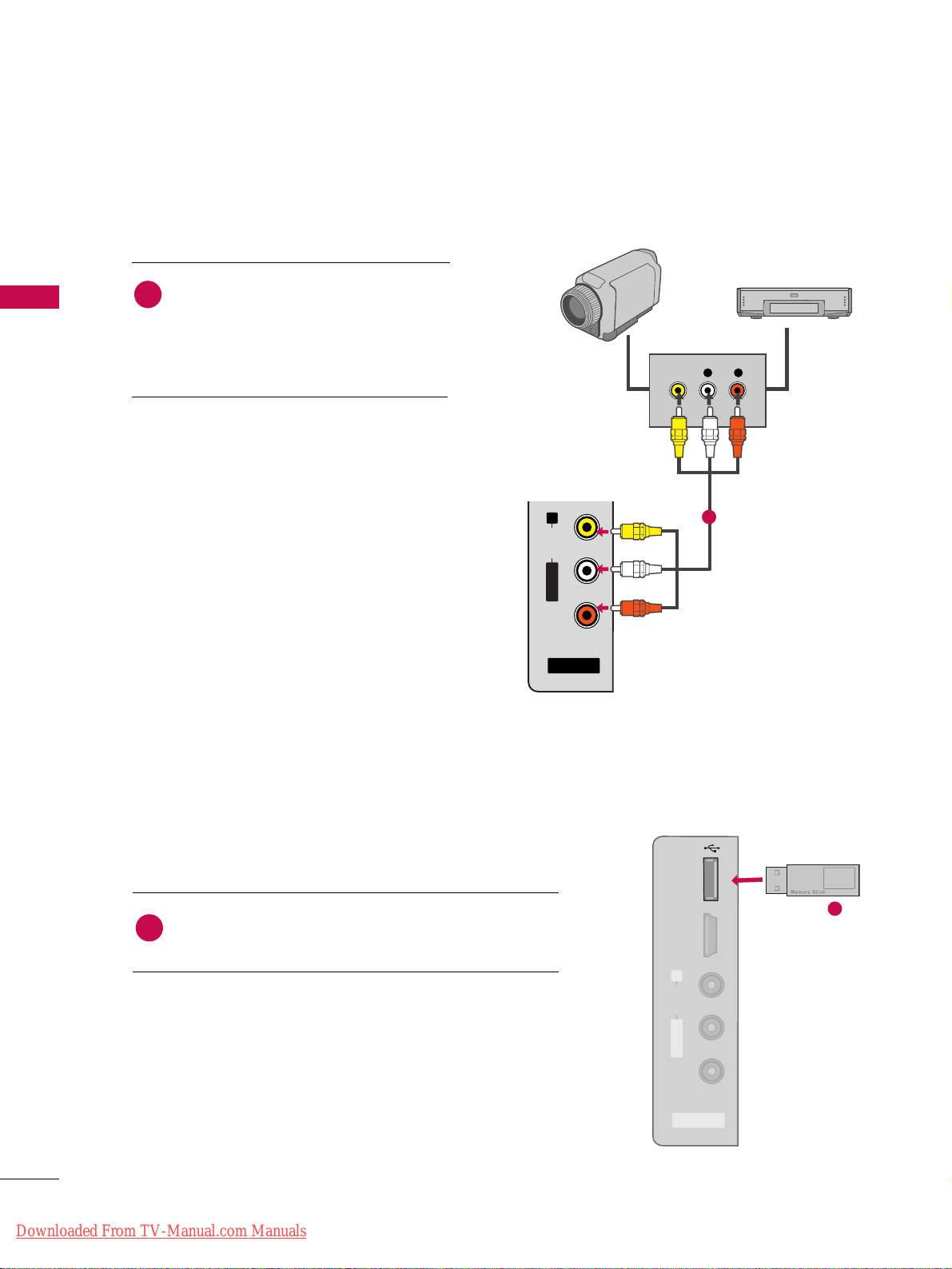
OTHER A/V SOURCE SETUP
L R
VIDEO
AV IN 2
L/ MONO
R
AUDIO
VIDEO
USB IN
HDMI IN 3
Camcorder
Video Game Set
Connect the
AAUUDDIIOO/VVIIDDEEOO
jacks
between TV and external equipment.
Match the jack colors
.
(
Video = yellow, Audio Left = white, and
Audio Right = red
)
1. How to connect
2. How to use
■
Select the
AAVV22
input source on the TV using
the
IINNPPUU TT
button on the remote control.
■
If connected to
AAVV IINN 11
input, select the
AAVV11
input source on the TV.
■
Operate the corresponding external equipment.
1
1
1
i.e)
Connect the USB device to the
UUSSBB II NN
jack on the side
of TV.
1. How to connect
1
2. How to use
■
After connecting the
UUSSBB II NN
jack, you use the USB function. (
GG
pp..5522
)
USB CONNECTION
- For 42/50PT350, 42/50PT350C, 50/60PV450, 50/60PV450C,
42/50PT250U, 50/60PV550U
Downloaded From TV-Manual.com Manuals
USB IN
HDMI IN 3
R
AUDIO
L/MONO
VIDEO
AV IN 2
EXTERNAL EQUIPMENT SETUP
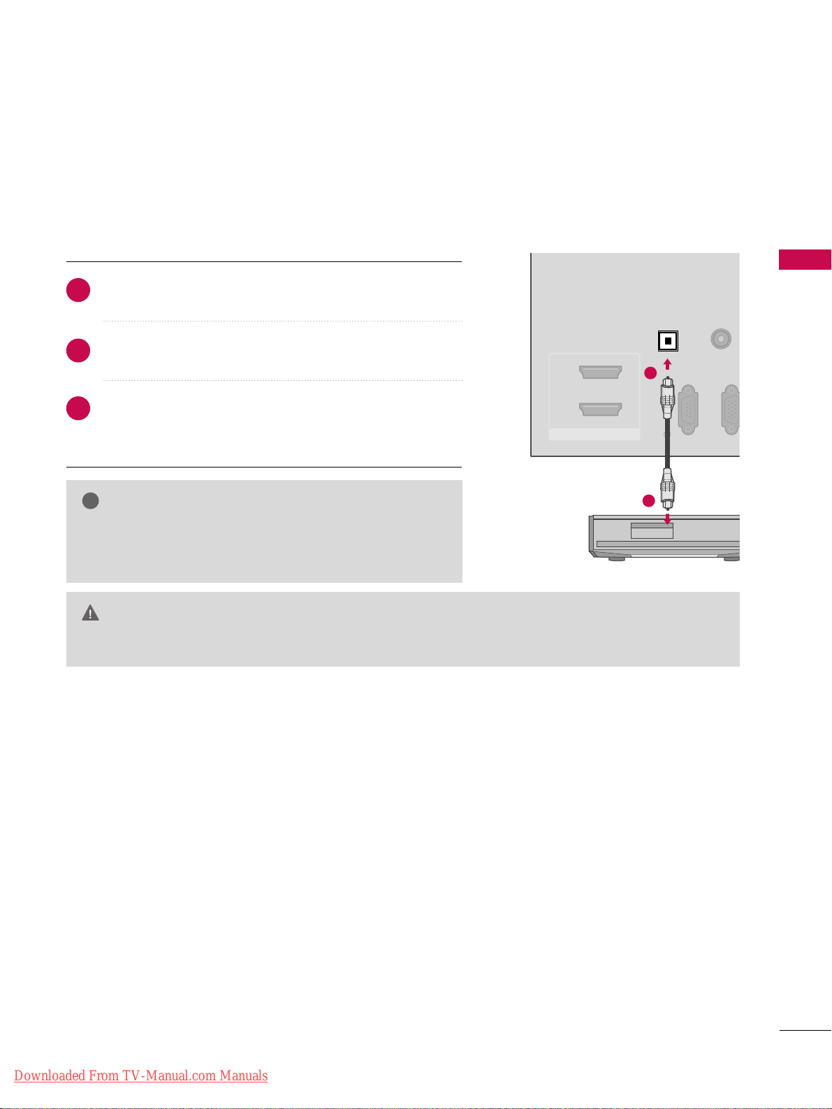
27
AUDIO OUT CONNECTION
RGB(PC)
RS-232C IN
(CONTROL & SERVICE)
AUDIO
(RGB/DVI)
HDMII/DVI IN
2
1
OPTICAL
DIGITAL
AUDIO OUT
1
2
GG
When connecting with external audio equipment, such as
amplifiers or speakers, you can turn the TV speakers off in
the menu. (
GG
pp..8888
)
NOTE
!
G
Do not look into the optical output port. Looking at the laser beam may damage your vision.
GG
Audio with ACP (Audio Copy Protection) function may block digital audio output.
CAUTION
Connect one end of the optical cable to the TV’s
OOPPTTIICCAALL
port of
DDIIGGIITTAALL AAUUDDIIOO OOUUTT
.
Connect the other end of the optical cable to the digital
audio input on the audio equipment.
Set the “TV Speaker option - Off” in the AUDIO menu. (
GG
pp..
8888
)
See the external audio equipment instruction manual for
operation.
1. How to connect
2
3
1
Send the TV’s audio to external audio equipment via the Audio Output port.
Downloaded From TV-Manual.com Manuals
EXTERNAL EQUIPMENT SETUP
28
EXTERNAL EQUIPMENT SETUP
PC SETUP
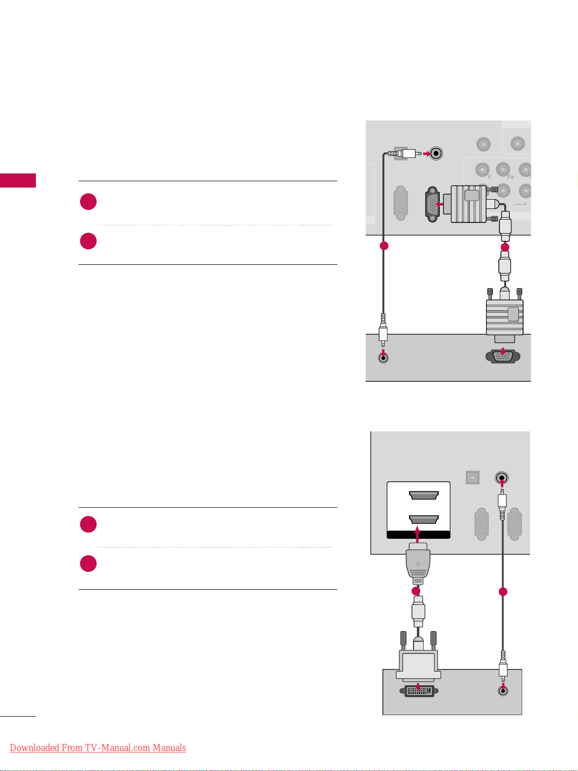
DVI to HDMI Connection
VGA (D-Sub 15 pin) Connection
(CONTROL & SERVICE)
OPTICAL
DIGITAL
AUDIO OUT
REMOTE
CONTROL IN
1
2
VIDEO
COMPONEN
VIDEO
RGB IN (PC)
AUDIO IN
(RGB/DVI)
AUDIO
RS-232C IN
1
RS-232C IN
RGB OUTPUT
RS-232C IN
1
2
RS-232C IN
(CONTROL & SERVICE)
OPTICAL
DIGITAL
AUDIO OUT
RGB IN (PC)
AUDIO IN
(RGB/DVI)
HDMI/DVI IN
2
1
DVI-PC OUTPUT AUDIO
1
2
2. How to use
■
Turn on the PC and the TV.
■
Select the
RRGGBB--PPCC
input source on the TV using the
IINNPPUU TT
button on the remote control.
Connect the VGA output of the PC to the
RRGGBB II NN
((
PPCC
))
jack on the TV.
Connect the PC audio output to the
AAUUDDII OO IINN
((
RRGGBB//DDVVII
))
jack on the TV.
1. How to connect
2
1
2. How to use
■
Turn on the PC and the TV.
■
Select the
HHDDMMII11
or
22
input source on the TV using the
IINNPPUU TT
button on the remote control.
Connect the DVI output of the PC to the
HHDDMMII//DDVVII
IINN 11
or
22
jack on the TV.
Connect the PC audio output to the
AAUUDDII OO IINN
((RR GGBB//DDVVII))
jack on the TV.
1. How to connect
2
1
Downloaded From TV-Manual.com Manuals
EXTERNAL EQUIPMENT SETUP
29
GG
Depending on the graphics card, DOS mode may
not work if a HDMI to DVI Cable is in use.
GG
In PC mode, there may be noise associated with
the resolution, vertical pattern, contrast or brightness. If noise is present, change the PC output to
another resolution, change the refresh rate to
another rate or adjust the brightness and contrast
on the PICTURE menu until the picture is clear.
GG
Avoid keeping a fixed image on the screen for a
long period of time. The fixed image could become
permanently imprinted on the screen.
GG
The synchronization input form for Horizontal and
Vertical frequencies is separate.
GG
Depending on the graphics card, some resolution
settings may not allow the image to be positioned on the screen properly.
NOTE
!
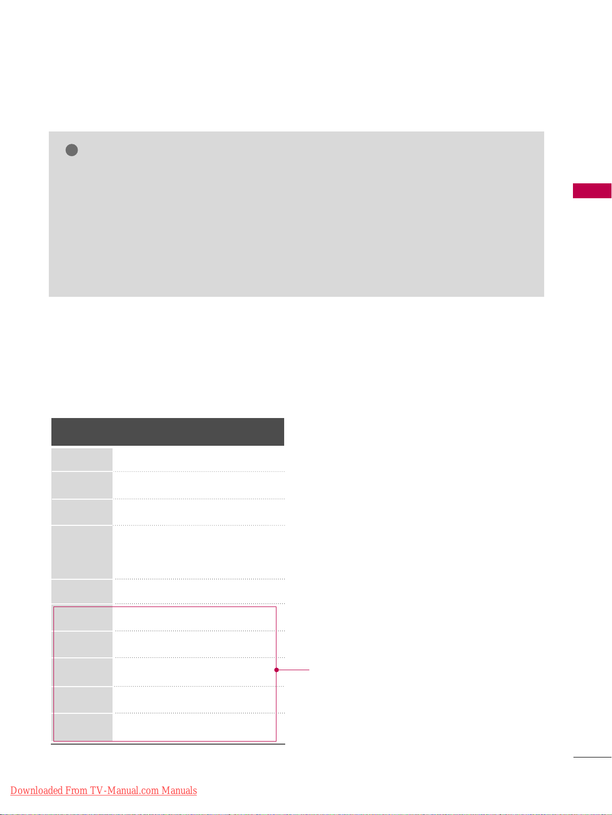
Supported Display Specifications
(RGB-PC, HDMI-PC)
Resolution
640x350
1024x768
720x400
640x480
800x600
1280x768
Horizontal Vertical
Frequency(KHz)Frequency(Hz
)
31.468 70.09
31.469 70.08
31.469 59.94
35.156 56.25
37.879 60.31
48.363 60.00
47.776 59.87
47.712 60.015
63.981 60.020
74.537 59.869
66.587 59.934
1360x768
1280x1024
1600x1200
1920x1080
For 50/60PV400,
50/60PV430, 50/60PV450,
50/60PV450C, 50/60PV550U
Downloaded From TV-Manual.com Manuals
EXTERNAL EQUIPMENT SETUP
30
EXTERNAL EQUIPMENT SETUP
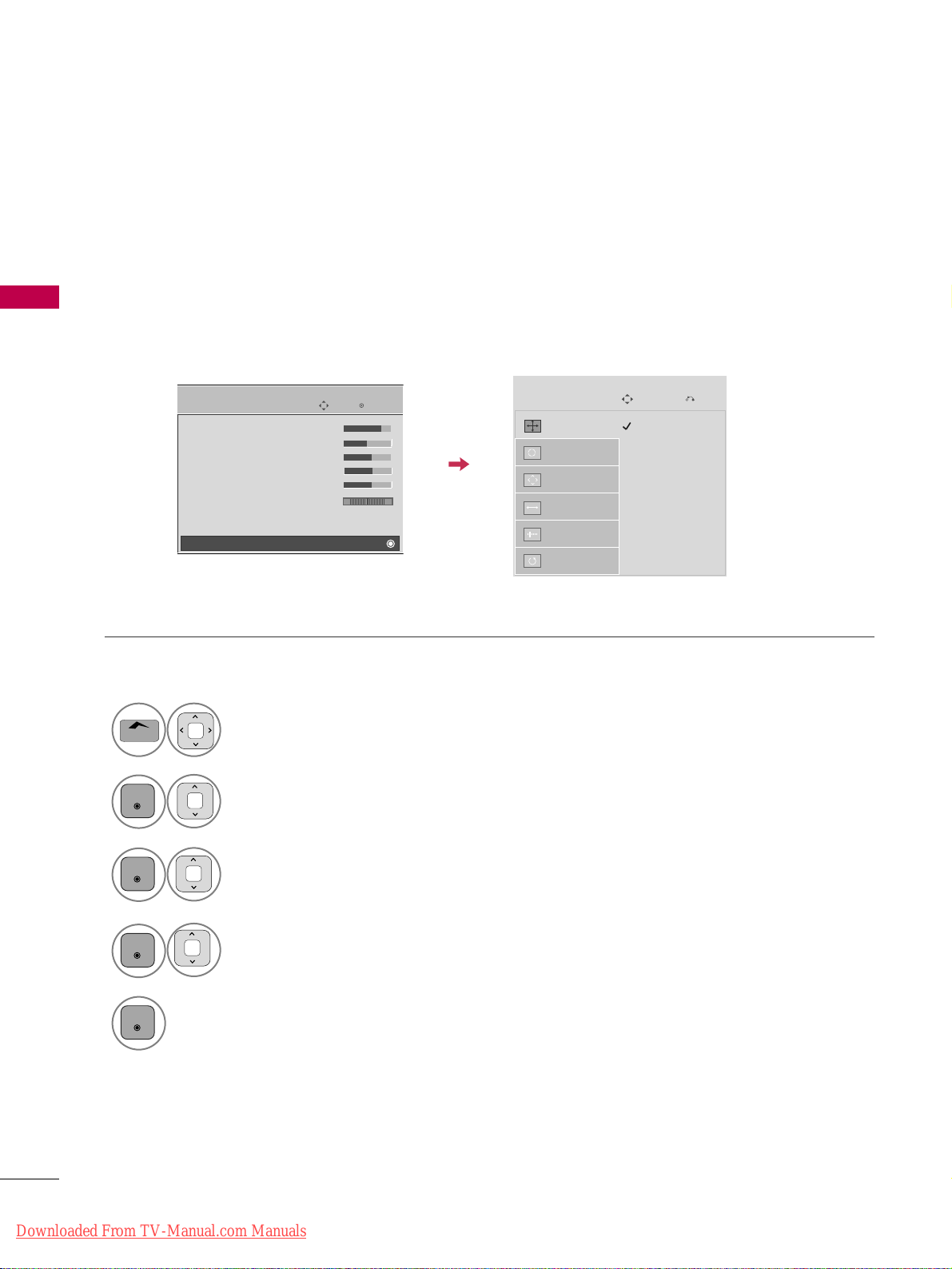
Screen Setup for PC mode
Selecting Resolution
You can choose the resolution in RGB-PC mode.
The
PPoossiittiioonn, PPhhaassee
, and
SSiizzee
can also be adjusted.
Select
PPIICCTTUURREE
.
Select
SS ccrreeeenn ((RRGG BB--PPCC))
.
Select
RReessoolluuttiioonn
.
Select the desired resolution.
1024 x 768
1280 x 768
1360 x 768
Auto config.
Resolution
G
Position
Size
Phase
Reset
Screen
Move
1
Home
3
4
2
ENTER
ENTER
ENTER
5
ENTER
Enter
Move
PICTURE
• Contrast 90
• Brightness 50
• H Sharpness 60
• V Sharpness 60
• Color 60
• Tint 0
• Expert Control
• Reset
Screen (RGB-PC)
RG
E
Prev.
Downloaded From TV-Manual.com Manuals
 Loading...