

Page 1

The model and serial number of the TV is located
on the back and one side of the TV.
Record it below should you ever need service.
MODEL
SERIAL
OWNER’S MANUAL
PLASMA TV
Please read this manual carefully before operating
your set and retain it for future reference.
50PV250
60PV250
42PT350
50PT350
50PV450
60PV450
P/NO : SAC? (1010-REV00)
www.lg.com
Page 2

WARNING / CAUTION
WARNING / CAUTION
To prevent fire or shock hazards, do not expose
this product to rain or moisture.
TO REDUCE THE RISK OF ELECTRIC SHOCK
DO NOT REMOVE COVER (OR BACK). NO
USER SERVICEABLE PARTS INSIDE. REFER TO
QUALIFIED SERVICE PERSONNEL.
The lightning flash with arrowhead
symbol, within an equilateral triangle, is
intended to alert the user to the presence
of uninsulated “dangerous voltage” within the
product’s enclosure that may be of sufficient
magnitude to constitute a risk of electric shock to
persons.
The exclamation point within an equilateral
triangle is intended to alert the user to
the presence of important operating and
maintenance (servicing) instructions in the literature accompanying the appliance.
WARNING/CAUTION
TO REDUCE THE RISK OF FIRE AND ELECTRIC
SHOCK, DO NOT EXPOSE THIS PRODUCT TO
RAIN OR MOISTURE.
FCC NOTICE
Class B digital device
This equipment has been tested and found to comply
with the limits for a Class B digital device, pursuant to
Part 15 of the FCC Rules. These limits are designed
to provide reasonable protection against harmful
interference in a residential installation. This equipment
generates, uses and can radiate radio frequency energy
and, if not installed and used in accordance with the
instructions, may cause harmful interference to radio
communications. However, there is no guarantee that
interference will not occur in a particular installation.
If this equipment does cause harmful interference to
radio or television reception, which can be determined
by turning the equipment off and on, the user is
encouraged to try to correct the interference by one
or more of the following measures:
- Reorient or relocate the receiving antenna.
- Increase the separation between the equipment and
receiver.
- Connect the equipment to an outlet on a circuit
different from that to which the receiver is connected.
- Consult the dealer or an experienced radio/TV
technician for help.
This device complies with part 15 of the FCC Rules.
Operation is subject to the following two conditions: (1) This device may not cause (harmful)
interference, and (2) this device must accept any
interference received, including interference that
may cause undesired operation (of the device).
NOTE TO CABLE/TV INSTALLER
This reminder is provided to call the CATV system
installer’s attention to Article 820-40 of the National
Electric Code (U.S.A.). The code provides guidelines for
proper grounding and, in particular, specifies that the
cable ground shall be connected to the grounding system
of the building, as close to the point of the cable entry
as practical.
Any changes or modifications not expressly approved
by the party responsible for compliance could void
the user’s authority to operate the equipment.
CAUTION
Do not attempt to modify this product in any way
without written authorization from LG Electronics.
Unauthorized modification could void the user’s
authority to operate this product
2
Page 3

SAFETY INSTRUCTIONS
IMPORTANT SAFETY INSTRUCTIONS
Read these instructions.
Keep these instructions.
Heed all warnings.
Follow all instructions.
Do not use this apparatus near water.
1
Clean only with soft dry cloth.
2
Do not block any ventilation openings. Install in
3
accordance with the manufacturer’s instructions.
Protect the power cord from being walked on
6
or pinched particularly at plugs, convenience
receptacles, and the point where they exit from
the apparatus.
Only use attachments/accessories specified by
7
the manufacturer.
Use only with the cart, stand, tripod, bracket,
8
or table specified by the manufacturer, or sold
with the apparatus. When a cart is used, use
caution when moving the cart/apparatus combination to avoid injury from tip-over.
Do not install near any heat sources such as
4
radiators, heat registers, stoves, or other
apparatus (including amplifiers)that produce
heat.
Do not defeat the safety purpose of the polarized
5
or grounding-type plug. A polarized plug has
two blades with one wider than the other. A
grounding type plug has two blades and a
third grounding prong, The wide blade or the
third prong are provided for your safety. If the
provided plug does not fit into your outlet,
consult an electrician for replacement of the
obsolete outlet.
Unplug this apparatus during lighting storms
9
or when unused for long periods of time.
Refer all servicing to qualified service personnel.
10
Servicing is required when the apparatus has
been damaged in any way, such as powersupply cord or plug is damaged, liquid has
been spilled or objects have fallen into the
apparatus, the apparatus has been exposed to
rain or moisture, does not operate normally, or
has been dropped.
3
Page 4

SAFETY INSTRUCTIONS
GROUNDI N G
DISCONNECTING DEVICE FROM MAINS
Never touch this apparatus or antenna during
11
a thunder or lighting storm.
When mounting a TV on the wall, make sure
12
not to install the TV by the hanging power and
signal cables on the back of the TV.
Do not allow an impact shock or any objects to
13
fall into the product, and do not drop onto the
screen with something.
CAUTION concerning the Power Cord:
14
It is recommend that appliances be placed
upon a dedicated circuit; that is, a single
outlet circuit which powers only that appliance
and has no additional outlets or branch
circuits. Check the specification page of this
owner's manual to be certain.
Do not connect too many appliances to the
same AC power outlet as this could result in
fire or electric shock.
Do not overload wall outlets. Overloaded wall
outlets, loose or damaged wall outlets, extension
cords, frayed power cords, or damaged or
cracked wire insulation are dangerous. Any of
these conditions could result in electric shock
or fire. Periodically examine the cord of your
appliance, and if its appearance indicates damage
or deterioration, unplug it, discontinue use of
the appliance, and have the cord replaced with
an exact replacement part by an authorized
servicer. Protect the power cord from physical
or mechanical abuse, such as being twisted,
kinked, pinched, closed in a door, or walked
upon. Pay particular attention to plugs, wall
outlets, and the point where the cord exits the
appliance.
Do not make the TV with the power cord
plugged in. Do not use a damaged or loose
power cord. Be sure do grasp the plug when
unplugging the power cord. Do not pull on the
power cord to unplug the TV.
WARNING - To reduce the risk of fire or electrical
15
shock, do not expose this product to rain,
moisture or other liquids. Do not touch the TV
with wet hands. Do not install this product
near flammable objects such as gasoline or
candles or expose the TV to direct air
conditioning.
Do not expose to dripping or splashing and do
16
not place objects filled with liquids, such as
vases, cups, etc. on or over the apparatus (e.g.
on shelves above the unit).
17
Ensure that you connect the earth ground wire
to prevent possible electric shock (i.e. a TV
with a three-prong grounded AC plug must be
connected to a three-prong grounded AC outlet). If grounding methods are not possible,
have a qualified electrician install a separate
circuit breaker.
Do not try to ground the unit by connecting it
to telephone wires, lightening rods, or gas
pipes.
Short-circuit
Breaker
18
Mains plug is the disconnecting device. The
plug must remain readily operable.
Power
Supply
"As long as this unit is connected to the AC wall
19
outlet, it is not disconnected from the AC power
source even if you turn off this unit by SWITCH"
4
Page 5

ANTENN A S
Outdoor a n t e n n a ground i n g
Antenna grounding according to the
National Electrical Code, ANSI/NFPA 70
Cleanin g
Movin g
Ventilati o n
Dot D e fect
Generated Sound
20
If an outdoor antenna is installed, follow the
precautions below. An outdoor antenna system
should not be located in the vicinity of overhead power lines or other electric light or
power circuits, or where it can come in contact
with such power lines or circuits as death or
serious injury can occur.
Be sure the antenna system is grounded so as
to provide some protection against voltage
surges and built-up static charges.
Section 810 of the National Electrical Code
(NEC) in the U.S.A. provides information with
respect to proper grounding of the mast and
supporting structure, grounding of the lead-in
wire to an antenna discharge unit, size of
grounding conductors, location of antenna discharge unit, connection to grounding electrodes and requirements for the grounding
electrode.
23
Install your TV where there is proper ventilation. Do not install in a confined space such as
a bookcase. Do not cover the product with
cloth or other materials (e.g.) plastic while
plugged in. Do not install in excessively dusty
places.
Take care not to touch the ventilation open-
24
ings. When watching the TV for a long period,
the ventilation openings may become hot.
If you smell smoke or other odors coming from
25
the TV or hear strange sounds, unplug the power
cord contact an authorized service center.
Do not press strongly upon the panel with
26
hand or sharp object such as nail, pencil or
pen, or make a scratch on it. Do not allow a
impact shock onto the panel.
NEC: National Electrical Code
21
When cleaning, unplug the power cord and
scrub gently with a soft cloth to prevent
scratching. Do not spray water or other liquids
directly on the TV as electric shock may occur.
Do not clean with chemicals such as alcohol,
thinners or benzene.
22
Make sure the product is turned off,
unplugged and all cables have been removed. It
may take 2 or more people to carry larger TVs.
Do not press against or put stress on the front
panel of the TV.
Keep the product away from direct sunlight.
27
28
The Plasma or LCD panel is a high technology
product with resolution of two million to six
million pixels. In a very few cases, you could see
fine dots on the screen while you’reviewing the
TV. Those dots are deactivated pixels and do
not affect the performance and reliability of the
TV.
29
“Cracking” noise: A cracking noise that occurs
when watching or turning off the TV is generated by plastic thermal contraction due to
temperature and humidity. This noise is common for products where thermal deformation
is required.
Electrical circuit humming/panel buzzing: A low
level noise is generated from a high-speed
switching circuit, which supplies a large
amount of current to operate a product. It
varies depending on the product.This generated sound does not affect the performance and
reliability of the product.
5
Page 6

CONTENTS
WARNING / CAUTION
SAFETY INSTRUCTIONS
FEATURE OF THIS TV
. . . . . . . . . . . . . . . . . . . . . . . . . . . . 2
. . . . . . . . . . . . . . . . . . . . . . . . . . 3
. . . . . . . . . . . . . . . . . . . . . . . . . . . . . . . 8
PREPARATION
Accessories . . . . . . . . . . . . . . . . . . . . . . . . . . . . . . . . . . . . . . . . . . . . . . . . . . . . . . 8
Front Panel Information
Back Panel Information
Stand Instruction
Cable Management . . . . . . . . . . . . . . . . . . . . . . . . . . . . . . . . . . . . . . . . . 15
Desktop Pedestal Installation
Swivel Stand . . . . . . . . . . . . . . . . . . . . . . . . . . . . . . . . . . . . . . . . . . . . . . . . . . . . 16
VESA Wall Mounting
Securing the TV to the wall to prevent falling
when the TV is used on a stand . . . . . . . . . . . . . . . . . . . . . . . . 18
Antenna or Cable Connection
. . . . . . . . . . . . . . . . . . . . . . . . . . . . . . . . . . . 10
. . . . . . . . . . . . . . . . . . . . . . . . . . . . . . . . . . . . . 11
. . . . . . . . . . . . . . . . . . . . . . . . . . . . . . . . . . . . . . . . . . . . . 13
. . . . . . . . . . . . . . . . . . . . . . . . . . . . 16
. . . . . . . . . . . . . . . . . . . . . . . . . . . . . . . . . . . . . . . . 17
. . . . . . . . . . . . . . . . . . . . . . . . . . 19
- Add / Delete Channel (Manual Tuning)
. . . . . . 41
- Channel Editing . . . . . . . . . . . . . . . . . . . . . . . . . . . . . . . . . . . . . . . . 42
Channel List . . . . . . . . . . . . . . . . . . . . . . . . . . . . . . . . . . . . . . . . . . . . . . . . . . . . 43
Favorite Channel Setup
. . . . . . . . . . . . . . . . . . . . . . . . . . . . . . . . . . . . 44
Favorite Channel List . . . . . . . . . . . . . . . . . . . . . . . . . . . . . . . . . . . . . . . 45
Brief Information
Input List
. . . . . . . . . . . . . . . . . . . . . . . . . . . . . . . . . . . . . . . . . . . . . . . . . . . . . . . . 47
Input Label
AV Mode
. . . . . . . . . . . . . . . . . . . . . . . . . . . . . . . . . . . . . . . . . . . . . . . . . . . . . . . . 49
. . . . . . . . . . . . . . . . . . . . . . . . . . . . . . . . . . . . . . . . . . . . . 46
. . . . . . . . . . . . . . . . . . . . . . . . . . . . . . . . . . . . . . . . . . . . . . . . . . . . . 48
SIMPLINK . . . . . . . . . . . . . . . . . . . . . . . . . . . . . . . . . . . . . . . . . . . . . . . . . . . . . . . 50
USB
Entry Modes . . . . . . . . . . . . . . . . . . . . . . . . . . . . . . . . . . . . . . . . . . . . . . . . . . . 52
Photo List
Music List
. . . . . . . . . . . . . . . . . . . . . . . . . . . . . . . . . . . . . . . . . . . . . . . . . . . . . . . 53
. . . . . . . . . . . . . . . . . . . . . . . . . . . . . . . . . . . . . . . . . . . . . . . . . . . . . . . 59
EXTERNAL EQUIPMENT SETUP
HD Receiver Setup . . . . . . . . . . . . . . . . . . . . . . . . . . . . . . . . . . . . . . . . . 20
DVD Setup . . . . . . . . . . . . . . . . . . . . . . . . . . . . . . . . . . . . . . . . . . . . . . . . . . . . . 23
VCR Setup
. . . . . . . . . . . . . . . . . . . . . . . . . . . . . . . . . . . . . . . . . . . . . . . . . . . . . 25
Other A/V Source Setup . . . . . . . . . . . . . . . . . . . . . . . . . . . . . . . . . 26
USB Connection . . . . . . . . . . . . . . . . . . . . . . . . . . . . . . . . . . . . . . . . . . . . . 26
Audio Out Connection
. . . . . . . . . . . . . . . . . . . . . . . . . . . . . . . . . . . 27
PC Setup . . . . . . . . . . . . . . . . . . . . . . . . . . . . . . . . . . . . . . . . . . . . . . . . . . . . . . . . 29
WATCHING TV / CHANNEL CONTROL
Remote Control Functions . . . . . . . . . . . . . . . . . . . . . . . . . . . . . . . 34
Turning On TV
Channel Selection . . . . . . . . . . . . . . . . . . . . . . . . . . . . . . . . . . . . . . . . . . . 36
Volume Adjustment
Initial Setting . . . . . . . . . . . . . . . . . . . . . . . . . . . . . . . . . . . . . . . . . . . . . . . . . . 37
On-Screen Menus Selection . . . . . . . . . . . . . . . . . . . . . . . . . . . . . 38
Quick Menu
Channel Setup
- Auto Scan (Auto Tuning)
. . . . . . . . . . . . . . . . . . . . . . . . . . . . . . . . . . . . . . . . . . . . . . . . 36
. . . . . . . . . . . . . . . . . . . . . . . . . . . . . . . . . . . . . . . . . 36
. . . . . . . . . . . . . . . . . . . . . . . . . . . . . . . . . . . . . . . . . . . . . . . . . . . 39
. . . . . . . . . . . . . . . . . . . . . . . . . . . 40
PICTURE CONTROL
Picture Size (Aspect Ratio) Control . . . . . . . . . . . . . . . . . . 62
Picture Wizard
Energy Saving
Preset Picture Settings(Picture Mode)
Manual Picture Adjustment - User Mode
Picture Improvement Technology
Expert Picture Control
Picture Reset
Demo Mode
Image Sticking Minimization (ISM) Method
. . . . . . . . . . . . . . . . . . . . . . . . . . . . . . . . . . . . . . . . . . . . . . . . . 64
. . . . . . . . . . . . . . . . . . . . . . . . . . . . . . . . . . . . . . . . . . . . 66
. . . . . . . . . . . . . . 67
. . . . . . . . . . 68
. . . . . . . . . . . . . . . . . . . . . 69
. . . . . . . . . . . . . . . . . . . . . . . . . . . . . . . . . . . . . 70
. . . . . . . . . . . . . . . . . . . . . . . . . . . . . . . . . . . . . . . . . . . . . . . . . 72
. . . . . . . . . . . . . . . . . . . . . . . . . . . . . . . . . . . . . . . . . . . . . . . . . . 72
. . . . . . . 73
6
Page 7

SOUND & LANGUAGE CONTROL
APPENDIX
Auto Volume Leveler (Auto Volume) . . . . . . . . . . . . . . . . . 74
Clear Voice II
Preset Sound Settings (Sound Mode)
Sound Setting Adjustment - User Mode
Balance
TV Speakers On/Off Setup
Audio Reset
Stereo/SAP Broadcasts Setup
Audio Language
On-Screen Menus Language Selection
. . . . . . . . . . . . . . . . . . . . . . . . . . . . . . . . . . . . . . . . . . . . . . . . . . 75
. . . . . . . . . . . . . . . 76
. . . . . . . . . . . 77
. . . . . . . . . . . . . . . . . . . . . . . . . . . . . . . . . . . . . . . . . . . . . . . . . . . . . . . . . . 79
. . . . . . . . . . . . . . . . . . . . . . . . . . . . . . 80
. . . . . . . . . . . . . . . . . . . . . . . . . . . . . . . . . . . . . . . . . . . . . . . . . . . 81
. . . . . . . . . . . . . . . . . . . . . . . . . . 82
. . . . . . . . . . . . . . . . . . . . . . . . . . . . . . . . . . . . . . . . . . . . . . 83
. . . . . . . . . . . . . 84
Caption Mode
- Analog Broadcasting System Captions
- Digital Broadcasting System Captions
- Caption Option
. . . . . . . . . . . . . . . . . . . . . . . . . . . . . . . . . . . . . . . 87
. . . . . . . 85
. . . . . . . . 86
TIME SETTING
Clock Setting
- Auto Clock Setup . . . . . . . . . . . . . . . . . . . . . . . . . . . . . . . . . . . . 88
- Manual Clock Setup
Auto On/Off Time Setting . . . . . . . . . . . . . . . . . . . . . . . . . . . . . . 90
Sleep Timer Setting
. . . . . . . . . . . . . . . . . . . . . . . . . . . . . . . . . 89
. . . . . . . . . . . . . . . . . . . . . . . . . . . . . . . . . . . . . . . . . 91
Troubleshooting . . . . . . . . . . . . . . . . . . . . . . . . . . . . . . . . . . . . . . . . . . . . 10 4
Maintenance
Product Specifications
IR Codes
External Control Through RS-232C
. . . . . . . . . . . . . . . . . . . . . . . . . . . . . . . . . . . . . . . . . . . . . . . . . 10 6
. . . . . . . . . . . . . . . . . . . . . . . . . . . . . . . . . . . 10 7
. . . . . . . . . . . . . . . . . . . . . . . . . . . . . . . . . . . . . . . . . . . . . . . . . . . . .10 8
. . . . . . . . . . . . . . . . .110
PARENTAL CONTROL / RATINGS
Set Password & Lock System . . . . . . . . . . . . . . . . . . . . . . . . . . . 92
Channel Blocking . . . . . . . . . . . . . . . . . . . . . . . . . . . . . . . . . . . . . . . . . . . . 95
Movie & TV Rating . . . . . . . . . . . . . . . . . . . . . . . . . . . . . . . . . . . . . . . . . 96
Downloadable Rating
External Input Blocking . . . . . . . . . . . . . . . . . . . . . . . . . . . . . . . . . . 10 2
Key lock
. . . . . . . . . . . . . . . . . . . . . . . . . . . . . . . . . . . . . . . . . . . . . . . . . . . . . . . . 10 3
. . . . . . . . . . . . . . . . . . . . . . . . . . . . . . . . . . . . . 101
7
Page 8

FEATURE OF THIS TV
■
This feature is not available for all models.
High-definition television. High-resolution digital
television broadcast and playback system composed
of roughly a million or more pixels, 16:9 aspect-ratio
screens, and AC3 digital audio. A subset of digital
television, HDTV formats include 1080i and 720p
resolutions.
This TV contains the detailed calibrations necessary
for professional certification by the Imaging Science
Foundation. The resulting ISF “day” and “night” modes
will then be accessible by the user to experience the
best their LG HDTV has to offer.
Sophisticated and detailed calibrations can be made
through the ISFccc mode.
Detailed calibration requires a licensed technician.
Please contact your local dealer to inquire about an
ISF certified technician.
AV Mode is three preset picture and audio settings. It
allows the viewer to quickly switch between common
settings. It includes Cinema, Sports, and Game Modes.
Automatically enhances and amplifies the sound of
human voice frequency range to help keep dialogue
audible when background noise swells.
Manufactured under license from Dolby Laboratories.
Dolby
“and the double-D symbol are trademarks of
“
Dolby Laboratories.
HDMI, the HDMI logo and High-Definition Multimedia
Interface are trademarks or registered trademarks of
HDMI Licensing LLC."
Unlike other sensors which can only sense brightness
of ambient light, LG’s “Intelligent Sensor” uses 4,096
sensing steps to evaluate its surroundings. Using a
sophisticated algorithm, the LG processes picture
quality elements including brightness, contrast, color,
sharpness and white balance. The result is a picture
optimized for it’s surroundings, more pleasing to
watch and which can also save up to 50% in power
consumption.
View videos and photos and listen to music on your
TV through USB 2.0 (‘videos’ dependent on model).
Displays HDTV programs in full 1920 x 1080p resolution for a more detailed picture.
IMPORTANT INFORMATION TO PREVENT “IMAGE BURN
/ BURN-IN” ON YOUR TV SCREEN
■
When a fixed image (e.g. logos, screen menus, video game, and computer display) is displayed on the TV
for an extended period, it can become permanently imprinted on the screen. This phenomenon is known
as “image burn” or “burn-in.” Image burn is not covered under the manufacturer’s warranty.
■
In order to prevent image burn, avoid displaying a fixed image on your TV screen for a prolonged period
(2 or more hours for LCD, 1 or more hours for Plasma).
■
Image burn can also occur on the letterboxed
areas of your TV if you use the 4:3 aspect
ratio setting for an extended period.
8
Page 9

PREPARATION
1.5V 1.5V
E
N
ER
GY
CH
VOL
O
N
/
O
FF
123
45
0
6
789
LIST
F
LASH
BK
M
A
R
K
FR
E
E
Z
E
SAV
ING
TV
A
V
M
OD
E
INP
UT
F
AV
RA
T
IO
M
EN
U
IN
F
O
Q
.M
EN
U
BACK
E
X
IT
E
N
T
E
R
M
UTE
P
A
G
E
Option Extras
AUDIO IN
(RGB/DVI)
ACCESSORIES
Ensure that the following accessories are included with your TV. If an accessory is missing, please contact the
dealer where you purchased the TV.
The accessories included may differ from the images below.
PREPARATION
Owner’s Manual Power Cord
CD Manual
Remote Control,
Batteries (AAA)
(For 50PV250, 50PT350)
x 4
M4x26
x 3
M5x14.5
Bolts for stand assembly
(Refer to P.15)
Polishing Cloth
(Not included with all models)
(For 60PV450)
x 4
M4x28
Bolts for stand assembly
(Refer to P.15)
* Wipe spots on the exterior only with
the polishing cloth.
* Do not wipe roughly when removing
stain. Excessive pressure may cause
scratch or discoloration.
x 3
M5x25
D-sub 15 pin Cable
(For 50PV250, 50PT350)
When using the VGA (D-sub 15 pin
cable) PC connection, the user must
use shielded signal interface cables
with ferrite cores to maintain standards compliance.
Protection Cover
(Refer to P.16)
x 1
Cable Holder
(For 60PV450)
x 2
Cable Holder
The ferrite core can be used to reduce the electromagnetic waves in the PC Audio cable.
Wind the PC Audio cable on the ferrite core twice, and
Ferrite Core
(Gray)
(This feature is not
available for all
then plug the cables into the TV as shown in the following picture.
Place the ferrite core close to AUDIO IN(RGB/DVI) jack
on the display.
models.)
Place the ferrite core close to
AUDIO IN(RGB/DVI) jack on the display.
Ferrite Core
(Black)
(This feature is not
available for all
models.)
Ferrite core can be used to reduce the electromagnetic waves that may interfere with the
TV. Install the Ferrite core on the power cable
close to the wall plug.
close to the wall plug.
9
Page 10

PREPARATION
FRONT PANEL INFORMATION
■
Image shown may differ from your TV.
PREPARATION
50/60PV250, 42/50PT350, 50/60PV450
Intelligent Sensor
Adjusts picture according to
the surrounding conditions.
Power/Standby Indicator
Illuminates red in standby
The LED is off while the TV
remains on.
POWER
Button
You can operate the button just by touching the button lightly with your finger.
INPUT
Button
HOME
Button
ENTER
Button
VOLUME
Buttons
mode.
Remote
Control
Sensor
CHANNEL
Buttons
10
Do not step on the glass stand or subject it to any impact.It may break, causing possible injury from fragments of
G
glass, or the TV may fall.
Do not drag the TV. The floor or the product may be damaged.
G
Page 11
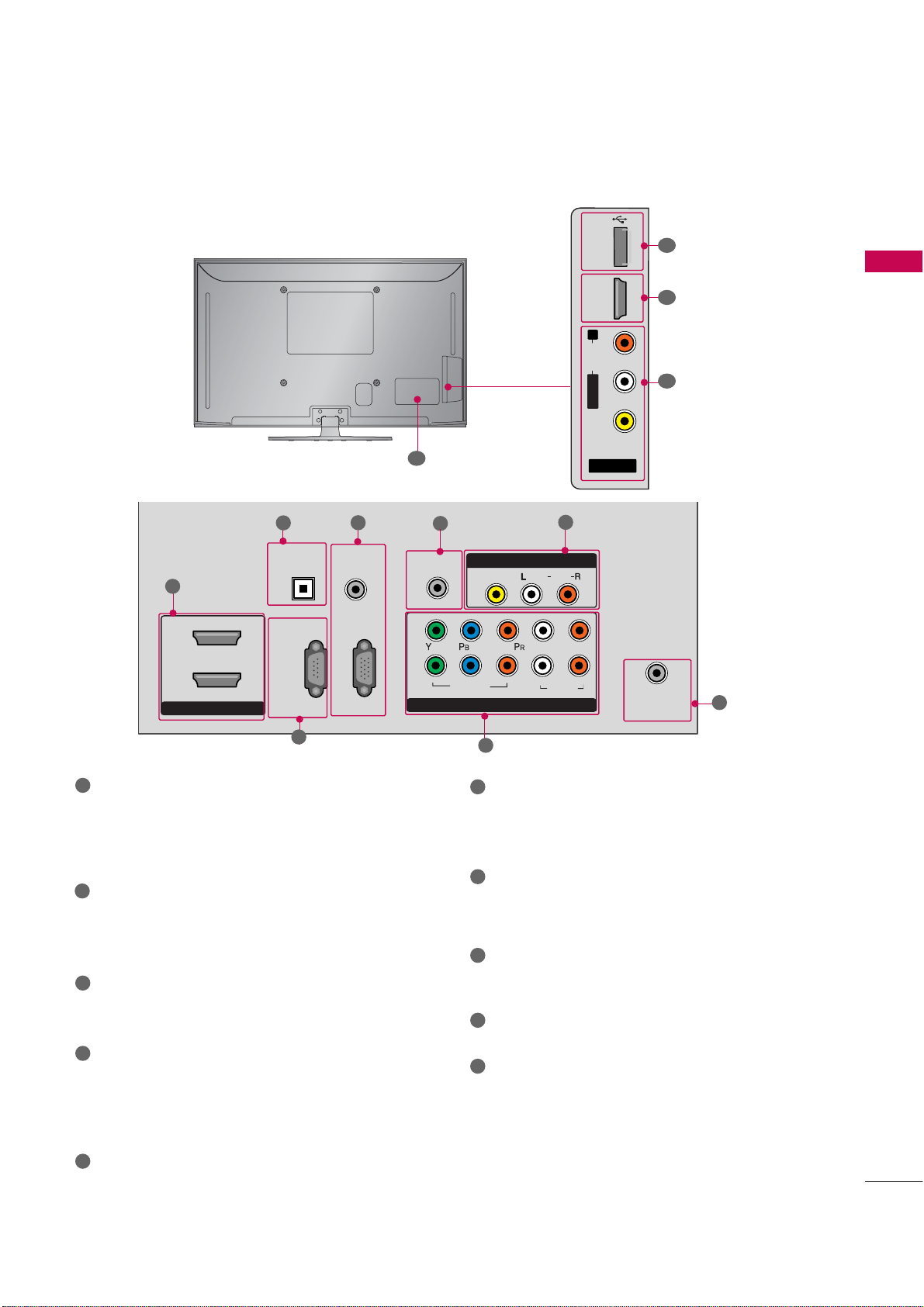
BACK PANEL INFORMATION
AV IN 2
L/ MONO
R
AUDIO
VIDEO
USB IN
HDMI IN 3
ANTENNA
/CABLE
IN
HDMI/DVI IN
2
1
RGB IN (PC)
RS-232C IN
(CONTROL & SERVICE)
OPTICAL
DIGITAL
AUDIO OUT
AUDIO IN
(RGB/DVI)
COMPONENT IN
1
2
VIDEO
AUDIO
L
R
REMOTE
CONTROL IN
AV IN 1
AUDIO
VIDEO
/MONO
■
Image shown may differ from your TV.
9
PREPARATION
1
7
10
4
1
HDMI/DVI IN
2
1
3
Digital Connection. Supports HD video and Digital
audio. Doesn’t support 480i.
Accepts DVI video using an adapter or HDMI to
DVI cable (not included)
2
OPTICAL DIGITAL AUDIO OUT
Optical digital audio output for use with amps and
home theater systems.
Note: In standby mode, this port doesn’t work.
RS-232C IN (CONTROL & SERVICE) PORT
3
Used by third party devices.
AUDIO IN (RGB)
4
1/8” headphone jack for analog PC audio input.
RGB IN (PC)
Analog PC Connection. Uses a D-sub 15 pin cable
(VGA cable).
REMOTE CONTROL IN PORT
5
For a wired remote control.
5
7
8
6
6
COMPONENT IN
Analog Connection. Supports HD.
Uses a red, green, and blue cable for video & red
and white for audio.
7
AV (Audio/Video) IN
Analog composite connection. Supports standard
definition video only (480i).
8
ANTENNA/CABLE IN
Connect over-the air signals to this jack.
Connect cable signals to this jack.
9
USB IN
Used for viewing photos and listening to MP3.
10
Power Cord Socket
For operation with AC power.
Caution: Never attempt to operate the TV on DC
power.
11
Page 12

PREPARATION
PREPARATION
12
Page 13
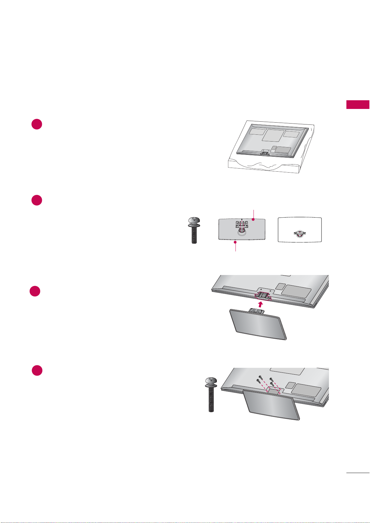
STAND INSTRUCTION
■
Image shown may differ from your TV.
Installation
Carefully place the TV screen side down on a
1
cushioned surface to protect the screen from
damage.
Assemble the parts of the Stand Body with the
2
Stand Base of the TV.
M5x25
PREPARATION
Stand Body
x 3
Stand Base
Assemble the TV as shown.
3
Fix the 4 bolts securely using the holes in the
4
back of the TV.
x 4
M4x28
13
Page 14

PREPARATION
protect i o n c o v er
PROT E CTION C OVER
Detachment
PREPARATION
Carefully place the TV screen side down on a
1
cushioned surface to protect the screen from
damage.
Loose the bolts from TV.
2
Detach the stand from TV.
3
Protection Cover
x 4
x 4
M4x28
PROTECTION COVER
(Fix a Guide to the Outsides.)
14
After removing the stand, install the included
over the hole for the stand.
Press the
until you hear it click.
into the TV
Page 15

CABLE MANAGEMENT
■
Image shown may differ from your TV.
After connecting the cables as necessary, install CABLE HOLDER as shown and bundle the cables.
1
To connect additional equipment, see EXTERNAL EQUIPMENT SETUP section.
PREPARATION
CABLE HOLDER
15
Page 16

PREPARATION
G
G
DESKTOP PEDESTAL INSTALLATION
■
Image shown may differ from your TV.
PREPARATION
For proper ventilation, allow a clearance of 4 inches on all four sides from the wall.
4 inches
4 inches
4 inches
4 inches
CAUTION
Ensure adequate ventilation by following the clearance recommendations.
G
Do not mount near or above any type of heat source.
SWIVEL STAND
(This feature is not available for all models.)
After installing the TV, you can adjust the TV manually to the left or right direction by 20 degrees to suit your
viewing position.
16
Page 17

VESA WALL MOUNTING
G
G
G
G
G
G
G
G
!
Install your wall mount on a solid wall perpendicular to the floor. When attaching to other building materials, please
contact your nearest installer.
If installed on a ceiling or slanted wall, it may fall and result in severe personal injury.
We recommend that you use an LG brand wall mount when mounting the TV to a wall.
LG recommends that wall mounting be performed by a qualified professional installer.
PREPARATION
NOTE
Model
50PV250,
60PV250,
42PT350,
50PT350,
50PV450,
60PV450,
VESA (A *B)
AA
BB
Standard Screw Quantity
400* 400 M6 4
Wall Mounting
bracket
(sold separately)
PSW400B,
PSW400BG
Screw length needed depends on the wall mount
used. For further information, refer to the instructions included with the mount.
Standard dimensions for wall mount kits are shown
in the table.
When purchasing our wall mount kit, a detailed
installation manual and all parts necessary for
assembly are provided.
Do not use screws longer then the standard dimension, as they may cause damage to the inside to
the TV.
For wall mounts that do not comply with the VESA
screws may differ depending on their specifications.
Do not use screws that do not comply with the
VESA standard screw specifications.
Do not use fasten the screws too strongly, this may
damage the TV or cause the TV to a fall, leading to
personal injury. LG is not liable for these kinds of
accidents.
LG is not liable for TV damage or personal injury
when a non-VESA or non specified wall mount is
used or the consumer fails to follow the TV installation instructions.
standard screw specifications, the length of the
CAUTION
Do not install your wall mount kit while your TV is turned on. It may result in personal injury due to electric shock.
17
Page 18

PREPARATION
G
G
!
SECURING THE TV TO THE WALL TO PREVENT FALLING
WHEN THE TV IS USED ON A STAND
PREPARATION
■
You should purchase necessary components to prevent the TV from tipping over (when not using a wall mount).
■
Image shown may differ from your TV.
We recommend that you set up the TV close to a wall so it cannot fall over if pushed backwards.
Additionally, we recommend that the TV be attached to a wall so it cannot be pulled in a forward direction,
potentially causing injury or damaging the product.
Caution: Please make sure that children don’t climb on or hang from the TV.
■
Insert the eye-bolts (or TV brackets and bolts) to tighten the product to the wall as shown in the picture.
*If your product has the bolts in the eye-bolts position before inserting the eye-bolts, loosen the bolts.
* Insert the eye-bolts or TV brackets/bolts and tighten them securely in the upper holes.
Secure the wall brackets with the bolts (sold separately) to the wall. Match the height of the bracket that is
mounted on the wall to the holes in the product.
Ensure the eye-bolts or brackets are tightened securely.
AW-50PG60MS
■
Use a sturdy rope (sold separately) to tie the product. It is safer to tie
the rope so it becomes horizontal between the wall and the product.
NOTE
Use a platform or cabinet strong enough and large enough to support
the size and weight of the TV.
To use the TV safely, make sure that the height of the bracket on the
wall and the one on the TV are the same.
18
Page 19

■
ANTENNA
/CABLE
IN
ANTENNA
/CABLE
IN
To prevent damage do not connect to the power outlet until all connections are made between the devices.
ANTENNA OR CABLE CONNECTION
1. Antenna (Analog or Digital)
Wall Antenna Socket or Outdoor Antenna without a Cable Box
Connection.
For optimum picture quality, adjust antenna direction if needed.
Wall
Multi-family Dwellings/Apartments
(Connect to wall antenna socket)
Antenna
Socket
Outdoor
RF Coaxial Wire (75 ohm)
Antenna
(VHF, UHF)
Single-family Dwellings /Houses
(Connect to wall jack for outdoor antenna)
(Only 60PS60)
2. Cable
Cable TV
Wall Jack
RF Coaxial Wire (75 ohm)
PREPARATION
Copper Wire
Be careful not to bend the copper wire
when connecting the antenna.
■
To improve the picture quality in a poor signal area, please purchase a signal amplifier and install properly.
■
If the antenna needs to be split for two TV’s, install a 2-Way Signal Splitter.
■
If the antenna is not installed properly, contact your dealer for assistance.
19
Page 20

COMPONE N T IN V IDEO 1
COMPONE N T IN AUDI O 1
Compo n e nt1
INP U T
COMPON E N T I N 2
Compo n e nt2
ANT
CA
O IN
REMOTE
CONTROL IN
AUDIO
VIDEO
/MONO
AV IN 1
COMPONENT IN
1
2
VIDEO
AUDIO
L
R
Y L RPBP
R
EXTERNAL EQUIPMENT SETUP
■
To prevent the equipment damage, never plug in any power cords until you have finished connecting all equipment.
■
Image shown may differ from your TV.
HD RECEIVER SETUP
This TV can receive Digital Over-the-air/Cable signals without an external digital set-top box. However, if you do
receive digital signals from a digital set-top box or other digital external device, refer to the figure as shown below.
EXTERNAL EQUIPMENT SETUP
Component Connection
1. How to connect
Connect the video outputs (Y, PB, PR
1
top box to the
the TV. Match the jack colors (Y = green, P
P
Connect the audio output of the digital set-top box to
2
the
2. How to use
■
Turn on the digital set-top box.
(
Refer to the owner’s manual for the digital set-top box. operation
■
Select the
■
If connected to
Supported Resolutions
Signal
480i
480p
720p
10 8 0 i
10 8 0 p
R = red).
input source on the TV using the
button on the remote control.
input source on the TV.
Component
Yes
Yes
Yes
Yes
Yes
)
of the digital set-
B = blue, and
jacks on the TV.
input, select the
HDMI
No
Yes
Yes
Yes
Yes
jacks on
)
Y, CB/PB, CR/PR
Resolution
720x480i
720x480p
1280x720p
1
2
Horizontal Vertical
Frequency(KHz)Frequency(Hz
15.73 59.94
15.73 60.00
31.47 59.94
31.47 60.00
44.96 59.94
45.00 60.00
)
20
1920x1080i
33.72 59.94
33.75 60.00
27.00 24.00
33.75 30.00
1920x1080p
67. 432 59.939
67.50 60.00
26.97 23.94
33.71 29.97
Page 21

HDMI Connection
HDMI/DVI IN 1
2
3
HDMI1, 2
INPUT
HDMI/DVI IN
2
1
HDMI-DTV OUTPUT
RGB IN(PC)
RS-232C IN
(CONTROL & SERVICE)
OPTICAL
DIGITAL
AUDIO OUT
AUDIO
(RGB/DVI)
G
G
!
1. How to connect
EXTERNAL EQUIPMENT SETUP
Connect the digital set-top box to
1
or
No separate audio connection is necessary.
2
HDMI supports both audio and video.
2. How to use
■
Turn on the digital set-top box.
(
Refer to the owner’s manual for the digital set-top box.
■
Select the
button on the remote control.
NOTE
Check HDMI cable over version 1.3.
If the HDMI cables don’t support HDMI version
1.3, it can cause flickers or no screen display. In
this case use the latest cables that support HDMI
version 1.3.
or 3 input source on the TV using the
,
)
HDMI-DTV
Resolution
1
Horizontal Vertical
Frequency(KHz)Frequency(Hz
)
HDMI mode supports PCM, AC-3(Dolby Digital)
audio format.
720x480p
1280x720p
1920x1080i
31.47 59.94
31.47 60.00
44.96 59.94
45.00 60.00
33.72 59.94
33.75 60.00
1920x1080p
27.00 24.00
33.75 30.00
67. 432 59.939
67.50 60.00
26.97 23.94
33.71 29.97
21
Page 22

EXTERNAL EQUIPMENT SETUP
RGB IN (PC)
RS-232C IN
(CONTROL & SERVICE)
OPTICAL
DIGITAL
AUDIO OUT
AUDIO IN
(RGB/DVI)
HDMI/DVI IN
2
1
LR
DVI-DTV OUTPUT
R
CO
1
2
G
!
HDMI/DVI IN 1, 2 or3
AUDIO IN (RGB/DV I )
HDMI1, 2
INPUT
DVI to HDMI Connection
1. How to connect
EXTERNAL EQUIPMENT SETUP
Connect the DVI output of the digital set-top box to the
1
Connect the audio output of the digital set-top box to
the
2
2. How to use
■
Turn on the digital set-top box. (Refer to the owner’s manual for the digital set-top box.
■
Select the
the
button on the remote control.
or 3 input source on the TV using
jack on the TV.
jack on the TV.
)
1
2
NOTE
A DVI to HDMI cable or adapter is required for this
connection. DVI doesn't support audio, so a separate
audio connection is necessary.
22
Page 23

DVD SETUP
COMPONE N T IN VIDE O 1
COMPONE N T IN AUDI O 1
Compo n e nt1
INP U T
COMPON E N T I N 2
Compo n e nt2
A
REMOTE
CONTROL IN
AUDIO
VIDEO
/MONO
AV IN 1
COMPONENT IN
1
2
VIDEO
AUDIO
L
R
Y L RPBP
R
Component Connection
1. How to connect
)
Connect the video outputs (Y, PB, PR
1
Match the jack colors (Y = green, P
jacks on the TV.
of the DVD to the
B = blue, and PR = red
Connect the audio outputs of the DVD to the
2
jacks on the TV.
2. How to use
■
Turn on the DVD player, insert a DVD.
■
Select the
the
■
If connected to
■
Refer to the DVD player's manual for operating instructions.
button on the remote control.
input source on the TV.
input source on the TV using
input, select the
EXTERNAL EQUIPMENT SETUP
)
.
1 2
Component Input ports
To get better picture quality, connect a DVD player to the component input ports as shown below.
Component ports on the TV
Video output ports
on DVD player
YPBP
B
Y
Y
Y
Y
P
B-Y
Cb
Pb
P
R-Y
Cr
Pr
R
R
23
Page 24

EXTERNAL EQUIPMENT SETUP
HDMI/DVI IN 1, 2
3
HDMI1, 2
INP U T
HDMI/DVI IN
2
1
RGB IN (PC)
RS-232C IN
(CONTROL & SERVICE)
OPTICAL
DIGITAL
AUDIO OUT
AUD
(RGB/D
HDMI-DVD OUTPUT
HDMI Connection
1. How to connect
EXTERNAL EQUIPMENT SETUP
Connect the HDMI output of the DVD to the
1
or
jack on the TV.
No separate audio connection is necessary.
2
HDMI supports both audio and video.
2. How to use
■
Select the
the
■
Refer to the DVD player's manual for operating instructions.
button on the remote control.
or 3 input source on the TV using
1
24
Page 25

VCR SETUP
CABLE
IN
L R
S-VIDEO VIDEO
OUTPUT
SWITCH
ANT IN
ANT OUT
ANTE N NA/CABLE I N
AUD I O/VID E O
AV 1
INP U T
AV IN 2
AV2
G
AUDIO L/M O N O
!
(PC)
REMOTE
CONTROL IN
1
2
AV IN 1
L
R
AUDIO
VIDEO
/MONO
L R
S-VIDEO VIDEO
OUTPUT
SWITCH
ANT IN
ANT OUT
Antenna Connection
1. How to connect
Connect the RF antenna out socket of the
1
VCR to the
on the TV.
Connect the antenna cable to the RF
2
antenna in socket of the VCR.
2. How to use
■
Set VCR output switch to 3 or 4 and then
tune TV to the same channel number.
■
Insert a video tape into the VCR and press
PLAY on the VCR. (Refer to the VCR owner’s
manual.
)
Composite (RCA) Connection
1. How to connect
socket
EXTERNAL EQUIPMENT SETUP
1
Wall Jack
2
Antenna
2. How to use
Connect the
1
VCR. Match the jack colors (Video = yellow, Audio Left
= white, and Audio Right = red)
■
Insert a video tape into the VCR and press PLAY on the
VCR. (Refer to the VCR owner’s manual.
■
Select the
input source on the TV using the
jacks between TV and
)
button on the remote control.
■
If connected to
, select
input source on the
TV.
NOTE
If you have a mono VCR, connect the audio cable
from the VCR to the
TV.
jack of the
1
25
Page 26

EXTERNAL EQUIPMENT SETUP
L R
VIDEO
AV IN 2
L/ MONO
R
AUDIO
VIDEO
USB IN
HDMI IN 3
AUDIO/VIDEO
AV 2
INP U T
AV IN 1
AV 1
AV IN 2
L/ MONO
R
AUDIO
VIDEO
USB IN
HDMI IN 3
USB I N
USB I N
G
p.52
OTHER A/V SOURCE SETUP
1. How to connect
Connect the
1
EXTERNAL EQUIPMENT SETUP
between TV and external equipment.
Match the jack colors
(
Audio Right = red
2. How to use
■
Select the
the
■
If connected to
input source on the TV.
■
Operate the corresponding external equipment.
jacks
.
Video = yellow, Audio Left = white, and
)
input source on the TV using
button on the remote control.
input, select the
Camcorder
Video Game Set
1
26
USB CONNECTION
- For 50/60PV250, 42/50PT350, 50/60PV450 models
1. How to connect
Connect the USB device to the
1
of TV.
2. How to use
■
After connecting the
jack, you use the USB function. (
jack on the side
i.e)
1
)
Page 27

AUDIO OUT CONNECTION
RGB(PC)
RS-232C IN
(CONTROL & SERVICE)
AUDIO
(RGB/DVI)
HDMII/DVI IN
2
1
OPTICAL
DIGITAL
AUDIO OUT
G
G
p.80
!
G
OPTICAL
DIGITAL AUDIO OUT
G
p.
80
Send the TV’s audio to external audio equipment via the Audio Output port.
1. How to connect
Connect one end of the optical cable to the TV’s
1
port of
.
Connect the other end of the optical cable to the digital
2
audio input on the audio equipment.
Set the “TV Speaker option - Off” in the AUDIO menu. (
3
See the external audio equipment instruction manual for
operation.
).
NOTE
When connecting with external audio equipment, such as
amplifiers or speakers, you can turn the TV speakers off in
)
the menu. (
CAUTION
Do not look into the optical output port. Looking at the laser beam may damage your vision.
G
Audio with ACP (Audio Copy Protection) function may block digital audio output.
EXTERNAL EQUIPMENT SETUP
1
2
27
Page 28

EXTERNAL EQUIPMENT SETUP
(CONTROL & SERVICE)
OPTICAL
DIGITAL
AUDIO OUT
REMOTE
CONTROL IN
1
2
VIDEO
COMPONEN
VIDEO
RGB IN (PC)
AUDIO IN
(RGB/DVI)
AUDIO
RS-232C IN
1
RS-232C IN
RGB OUTPUT
RS-232C IN
RS-232C IN
(CONTROL & SERVICE)
OPTICAL
DIGITAL
AUDIO OUT
RGB IN (PC)
AUDIO IN
(RGB/DVI)
HDMI/DVI IN
2
1
DVI-PC OUTPUT AUDIO
RGB- P C
INP U T
RGB IN
(
P C
)
AUDIO IN
(
RGB/ D V I
)
HDMI1, 2
INP U T
HDMI/DVI
IN 1
AUDIO IN
(RGB/ D V I)
PC SETUP
This TV provides Plug and Play capability, meaning that the PC adjusts automatically to the TV's settings.
VGA (D-Sub 15 pin) Connection
EXTERNAL EQUIPMENT SETUP
1. How to connect
Connect the VGA output of the PC to the
1
Connect the PC audio output to the
2
2. How to use
■
Turn on the PC and the TV.
■
Select the
DVI to HDMI Connection
jack on the TV.
jack on the TV.
input source on the TV using the
button on the remote control.
2
1
28
1. How to connect
1
2
Connect the DVI output of the PC to the
Connect the PC audio output to the
2. How to use
■
Turn on the PC and the TV.
■
Select the
the
, 2or 3 jack on the TV.
jack on the TV.
or 3 input source on the TV using
button on the remote control.
1
2
Page 29

G
G
G
G
G
NOTES
!
Depending on the graphics card, DOS mode may
not work if a HDMI to DVI Cable is in use.
In PC mode, there may be noise associated with
the resolution, vertical pattern, contrast or brightness. If noise is present, change the PC output to
another resolution, change the refresh rate to
another rate or adjust the brightness and contrast
on the PICTURE menu until the picture is clear.
Supported Display Specifications
(RGB-PC, HDMI-PC)
Resolution
640x350
Horizontal Vertical
Frequency(KHz)Frequency(Hz
31.468 70.09
Avoid keeping a fixed image on the screen for a
long period of time. The fixed image could become
permanently imprinted on the screen.
The synchronization input form for Horizontal and
Vertical frequencies is separate.
Depending on the graphics card, some resolution
settings may not allow the image to be positioned on the screen properly.
)
EXTERNAL EQUIPMENT SETUP
720x400
640x480
800x600
1024x768
1280x768
1360x768
1280x1024
1600x1200
1920x1080
31.469 70.08
31.469 59.94
35.156 56.25
37.879 60.31
48.363 60.00
47.776 59.87
47.712 60.015
63.981 60.020
74.537 59.869
66.587 59.934
29
Page 30

EXTERNAL EQUIPMENT SETUP
Pos ition, Phase
Size
PICT U R E
Screen (RGB - P C)
Resol u t ion
Home
ENTER
ENTER
ENTER
ENTER
Screen Setup for PC mode
EXTERNAL EQUIPMENT SETUP
Selecting Resolution
You can choose the resolution in RGB-PC mode.
The
Screen (RGB-PC)
1
PICTURE
, and
• Contrast 90
• Brightness 50
• H Sharpness 60
• V Sharpness 60
• Color 60
• Tint 0
• Expert Control
• Reset
Select
can also be adjusted.
Move
E
Enter
RG
.
Screen
Resolution
Auto config.
Position
Size
Phase
Reset
G
Move
1024 x 768
1280 x 768
1360 x 768
MENU
Prev.
30
2
3
4
5
Select
.
Select
.
Select the desired resolution.
Page 31

Auto Configure
Screen (RGB - P C)
Auto conf i g .
ENTER
ENTER
Ye s
ENTER
ENTER
PICT U R E
Home
Posit i on, Siz e
Pha s e
Automatically adjusts picture position and minimizes image instability. After adjustment, if the image is still
not correct, try using the manual settings or a different resolution or refresh rate on the PC.
MENU
Screen
Resolution
Move
Prev.
EXTERNAL EQUIPMENT SETUP
1
2
3
4
Select
Select
Select
Select
.
Auto config.
Position
Size
Phase
Reset
G
To Set
Yes No
.
.
.
5
Start Auto Configuration.
• If the position of the image is still not correct, try Auto adjustment again.
• If picture needs to be adjusted again after Auto adjustment in RGB-PC, you can adjust the
or
.
31
Page 32

EXTERNAL EQUIPMENT SETUP
Posit i on, Siz e
Pha s e
ENTER
ENTER
Posit i on
Siz e
Ph as e
PICT U R E
Screen (RGB - P C)
Home
ENTER
ENTER
Adjustment for screen Position, Size, and Phase
If the picture is not clear after auto adjustment and especially if characters are still trembling, adjust the picture
phase manually.
EXTERNAL EQUIPMENT SETUP
This feature operates only in RGB-PC mode.
PICTURE
• Contrast 90
• Brightness 50
• H Sharpness 60
• V Sharpness 60
• Color 60
• Tint 0
• Expert Control
• Reset
Screen (RGB-PC)
Move
E
Enter
RG
Screen
Resolution
Auto config.
Position
Size
Phase
Reset
Move
MENU
Prev.
G
D
GF
E
1
2
3
4
5
Select
.
Select
.
Select
, or
Make appropriate adjustments.
■
: This function is to adjust picture to left/right and up/down as you
prefer.
■
: This function is to minimize any
.
vertical bars or stripes visible on the
screen background. And the horizontal
screen size will also change.
■
: This function allows you to
remove any horizontal noise and clear or
sharpen the image of characters.
32
Page 33

Screen Reset (Reset to original factory values)
Posi t i on, Siz e
Pha s e
Res e t
ENTER
PICT U R E
Screen (RGB - P C)
Home
ENTER
Ye s
ENTER
ENTER
Returns
, and
to the default factory settings.
This feature operates only in RGB-PC mode.
PICTURE
Screen (RGB-PC)
E
• Contrast 90
• Brightness 50
• H Sharpness 60
• V Sharpness 60
• Color 60
• Tint 0
• Expert Control
• Reset
Move
RG
1
Select
.
Enter
Screen
Resolution
Auto config.
Position
Size
Phase
Reset
Move
Initialize Settings.
Yes No
G
MENU
EXTERNAL EQUIPMENT SETUP
Prev.
2
3
4
5
Select
Select
Select
.
.
.
33
Page 34

WATCHING TV / CHANNEL CONTROL
ENERGY
CHVOL
LIGHT
123
4506
789
LIST
FLASHBK
MARK
FREEZE
SAVING
TV
AV MODE INPUT
FAV
RATIO
Home
Q.MENU
BACK
EXIT
ENTER
MUTE
P
A
G
E
INFO
G
p.49
G
p.47
REMOTE CONTROL FUNCTIONS
When using the remote control, aim it at the remote control sensor on the TV.
WATCHING TV / CHANNEL CONTROL
ENERGY SAVING
AV MODE
NUMBER button
— (DASH)
FLASHBK
POWER
LIGHT
INPUT
TV
LIST
Turns the TV on from standby or off to standby.
Illuminates the remote control buttons.
Adjusts the Energy Saving.
Toggles through preset Video and Audio modes.
Rotates through inputs.
Also switches the TV on from standby.
Select the remote operating mode: TV
Used to enter a program number for multiple program
channels such as 2-1, 2-2, etc.
Displays the channel list.
Tunes to the last channel viewed.
34
Color
Control buttons
button
SIMPLINK
FREEZE
Access special functions in some menus
Controls MY MEDIA menu.
Controls the SIMPLINK compatible devices.
Freezes the current frame.
Page 35

VOLUME UP
G
p.45
G
p.36
/DOWN
Adjusts the volume.
FAV
MARK
RATIO
MUTE
CHANNEL
UP/DOWN
PAGE
UP/DOWN
INFO
Home
Q.MENU
THUMBSTICK
(Up/Down/Left
Right/ENTER)
BACK
Scroll through the programmed Favorite channels.
Select the input to apply the Picture Wizard setting.
Use to mark or unmark a photo/music/movie.
Changes the aspect ratio.
Switches the sound on or off.
Changes the channel.
Moves from one full set of screen information to the next one.
Displays channel information at the top of the screen.
Displays the main menu or clears all on-screen displays and returns to TV viewing.
Opens the list of Quick Menu options.
Navigates the on-screen menus and adjusts the system settings to your preference.
Allows the user to move return one step in an interactive application or other user interaction
function.
WATCHING TV / CHANNEL CONTROL
SIMPLINK
Displays channel information at the top of the screen.
Clears all on-screen displays and return to TV viewing from any menu.
EXIT
Installing Batteries
■
Open the battery compartment cover on the back side and install
the batteries matching correct polarity.
■
Install two 1.5V AAA batteries. Don’t mix old or used batteries with
new ones.
■
Close cover.
35
Page 36

WATCHING TV / CHANNEL CONTROL
!
G
INPUT,CH (
POWER
INPUT, CH(
Number (0~9)
INPUT
POWER
CH (
NUMBER
VOL (+
MUTE
MUTE
VOL (+
WATCHING TV / CHANNEL CONTROL
TURNING ON TV
First, connect power cord correctly.
1
At this moment, TV is in standby mode.
■
In standby mode to turn TV on, press the ,
or ),
button on the remote control.
or )button on the TV or press the
,
WATCHING TV / CHANNEL CONTROL
Select the viewing source by using the
2
When finished using the TV, press the
3
mode.
button on the remote control.
button on the remote control. The TV reverts to standby
NOTE
If you intend to be away on vacation, disconnect the power plug from the wall power outlet.
CHANNEL SELECTION
1
Press the
or )or
buttons to select a channel number.
VOLUME ADJUSTMENT
Adjust the volume to suit your personal preference.
Press the
1
If you want to switch the sound off, press the
2
You can cancel the Mute function by pressing the
3
36
or -)button to adjust the volume.
button.
or
or -)button.
Page 37

INITIAL SETTING
Hom e U s e
ENTER
Home U se
Home U se
Store Demo
Pict u r e
Pictur e mod e
Initial Setting
OPTION
Home Use
Initial setting
Initia l
setting
ENTER
Aut o
Manu a l
ENTER
F
G
Auto Tuni n g
ENTER
ENTER
This Function guides the user to easily set the essential items for viewing the TV for the first time when purchasing the TV. It will be displayed on the screen when turning the TV on for the first time. It can also be activated from the user menus.
■
Default selection is “
in your home environment.
■
“
menu store mode after 5 minutes.
■
You can also adjust
” Mode is only intended for use in retail environments. Customers can adjust the “
” manually while inspecting the TV, but the TV will automatically return to preset in-
Factory defaults are set when you choose “
■
If you do not complete the
procedure is completed.
Step1. Welcome
WELCOME !
Thank you for choosing LG
1
Step2. Language Selecting
”. We recommend setting the TV to “
in the
menu.
”.
, it will appear whenever the TV is switched on until the
Step4. Time setting
Next
Time Setting
Current Time Setting
Year
Month
Date
Hour
Minute
Time Zone
Daylight Saving
Previous
” mode for the best picture
Auto
2007
11
15
5 PM
52
Eastern
Off
Next
WATCHING TV / CHANNEL CONTROL
Language
English
Español
Français
1
Select
menu Language
Step3. Mode setting
Mode Setting
Selecting the environment.
Choose the setting mode you want.
Store Demo
Select [Home Use] to use this TV at
home. By Changing Picture Mode, you can
get picture quality you want.
Previous Next
Home Use
1
Select
Next
.
mode.
1
Select
2
or
Select desired time option.
Step5. Auto Tuning
Auto Tuning
Check your antenna connection.
The previous channel information will be updated
during Auto Tuning.
Previous
1
Start
.
Next
.
37
Page 38

WATCHING TV / CHANNEL CONTROL
Home
ENTER
ENTER
EXIT
ON-SCREEN MENUS SELECTION
Your TV's OSD (On Screen Display) may differ slightly from that shown in this manual.
WATCHING TV / CHANNEL CONTROL
CHANNEL
Auto Tuning
Manual Tuning
Channel Edit
OPTION
Language
Input Label
SIMPLINK : On
Key Lock : Off
Caption : Off
Demo Mode : Off
ISM Method : Normal
Set ID : 1
Initial Setting : Home Use
LOCK
Lock System : Off
Set Password
Block Channel
Movie Rating
TV Rating-Children
TV Rating-General
Downloadable Rating
Input Block
Move
Move
Move
Enter
Enter
Enter
Lock System : Off
Set Password
Block Channel
TV Rating-English
TV Rating-French
Downloadable Rating
Input Block
PICTURE
Aspect Ratio : 16:9
Picture Wizard
Energy Saving : Off
Picture Mode : Standard
CHANNEL
OPTION
PICTURE
LOCK
• Contrast 90
• Brightness 50
• Sharpness 60
• Color 60
• Tint 0
E
INPUT
TV
AV1
AV2
Component1
Component2
RGB-PC
HDMI1
HDMI2
HDMI3
Move
Enter
RG
AUDIO
INPUT
TIME
USB
Move
AUDIO
Auto Volume : Off
Clear Voice II : Off + 3
Balance 0
Sound Mode : Standard
TV Speaker : On
•
Infinte Sound:
• Treble 50
• Bass 50
• Reset
TIME
Clock
Off Time : Off
On Time : Off
Sleep Timer : Off
Enter
USB
Photo List
Music List
Move
Enter
LR
Off
Move
Enter
Move
Enter
For USA For Canada
1
Display each menu.
2
Select a menu item.
3
Accept the current selection.
4
Return to TV viewing.
38
Page 39

QUICK MENU
Q.MENU
F
G
CH
Aspect Ra t i o
Pic tur e Mode
Sound Mo d e
Multi Audio
SAP
Sleep Tim e r
Del/Add/Fav
Capt i o n
USB Devic e
CH
EXIT
Your TV's OSD (On Screen Display) may differ slightly from what is shown in this manual.
Q.Menu (Quick Menu) is a menu of features which users might use frequently.
: Selects your desired picture format.
Q.Menu
Aspect Ratio
Picture Mode
Sound Mode
Caption
Multi Audio
Sleep Timer
Del/Add/Fav
Eject USB
Close
16:9
Vivid
Standard
English
Add
Eject
Off
Off
depend on the viewing environment.
of program.
: Selects MTS sound (Analog signal).
turns off automatically.
add the channel to the Favorite List.
?
device.
: Select on or off.
: Selects the factory preset picture
: Selects the factory preset sound for type
: Changes the audio language (Digital signal).
: Select the amount of time before your TV
: Select channel you want to add/delete or
: Select “Eject” in order to eject a USB
WATCHING TV / CHANNEL CONTROL
1
Display each menu.
2
Make appropriate adjustments.
3
Return to TV viewing.
39
Page 40

WATCHING TV / CHANNEL CONTROL
CHAN N EL
Auto Tuni n g
Ye s
Home
ENTER
ENTER
BACK
Auto Tuni n g
ENTER
EXIT
WATCHING TV / CHANNEL CONTROL
CHANNEL SETUP
Auto Scan (Auto Tuning)
Automatically finds all channels available through antenna or cable inputs, and stores them in memory on the
channel list.
Run this function if you change your residence or move the TV. Also, make sure to run this function with the
antenna connected during TV broadcasting hours.
Auto Tuning memorizes only the channels available at the time.
WATCHING TV / CHANNEL CONTROL
1
2
3
4
5
CHANNEL
Auto Tuning
Manual Tuning
Channel Edit
Move
Enter
Select
Select
Select
Run
Return to the previous menu.
CHANNEL
Auto Tuning
Manual Tuning
Channel Edit
Move
Enter
Press ‘Yes’ button to begin
auto tuning.
Yes
No
Processing Auto Tuning...
23% DTV Channel 8
DTV : 0 Found Channel(s)
ATV : 0 Found Channel(s)
Next(TV)
Close
.
.
■
The TV will ask for a password if parental
control has been activated (LOCK
Menu). Use the password you set up in
.
the LOCK Menu to allow a channel
search.
■
When setting the Auto tuning or Manual
tuning, the number of maximum channel
.
you can store is 900.
It is subject to change depending on the
broadcasting signal environment.
■
Memorizes all the available channels in
the order of DTV, TV, CADTV and CATV.
Return to TV viewing.
40
Page 41

CHAN N EL
Home
ENTER
Add/Delete Channel (Manual Tuning)
Manual Tun i n g
DT V, T V, CAD T V
CAT V
ENTER
Add
Dele t e
ENTER
BACK
F
G
EXIT
If you select DTV or CADTV input signal, you can view the on-screen signal strength monitor to see the quality of the signal being received.
1
2
3
4
5
6
CHANNEL
Auto Tuning
Manual Tuning
Channel Edit
Select
Move
Enter
.
Select
Select
Select channel you want to add
or delete.
Select
or
Return to the previous menu.
CHANNEL
Auto Tuning
Manual Tuning
Channel Edit
Move
Enter
Select channel type and
RF-channel number.
Channel
DTV 2-1
Bad Normal Good
DTV
Delete
Close
WATCHING TV / CHANNEL CONTROL
2
.
■
The TV will ask for a password if parental
, or
.
control has been activated (LOCK
Menu). Use the password you set up in
the LOCK Menu to allow a channel
search.
■
When setting the Auto tuning or Manual
tuning, the number of maximum channel
.
you can store is 900.
It is subject to change depending on the
broadcasting signal environment.
Return to TV viewing.
41
Page 42

WATCHING TV / CHANNEL CONTROL
ENTER
CHAN N EL
Home
ENTER
Channe l E d i t
BACK
C H
EXIT
Channel Editing
When a channel number is deleted, it means that you will be unable to select it using CH , button during
TV viewing.
If you wish to select the deleted channel, directly enter the channel number with the NUMBER buttons or select
it in the Channel Edit menu.
WATCHING TV / CHANNEL CONTROL
1
2
3
CHANNEL
Auto Tuning
Manual Tuning
Channel Edit
Select
Select
Select a channel.
Move
Enter
Ch.Change
.
Move
■
Keep pressing the button and use the
CH
Move Page
Previous
Add/Delete
or buttons to move between DTV,
.
TV, CADTV and CATV.
■
If the channel list is too long, use the
or button to move between pages.
42
4
5
Blue
Add or delete the channel.
Return to the previous menu.
Return to TV viewing.
Page 43

CHANNEL LIST
Channe l L i s t
LIST
ENTER
CH
P
A
G
E
EXIT
You can check channels which are stored in the memory by displaying the channel list.
Channel List
This padlock is displayed
when the channel is locked
with parental control.
2-1
3-1
4-1
Displaying Channel List
1
Display the
.
Selecting a channel in the channel list
1
Select a channel.
WATCHING TV / CHANNEL CONTROL
Exit
2
Switch to the chosen channel number.
Paging through a channel list
1
2
Turn the pages.
Return to TV viewing.
43
Page 44

WATCHING TV / CHANNEL CONTROL
FAV
Del/Ad d /Fav
Q.MENU
CH
P
A
G
E
123
4506
789
Favor i te
CH
F
G
EXIT
FAVORITE CHANNEL SETUP
Your TV's OSD (On Screen Display) may differ slightly from what is shown in this manual.
Favorite Channels are a convenient feature that lets you quickly select channels of your choice without waiting
for the TV to select through all the in-between channels.
To tune to a favorite channel, press the
(Favorite) button repeatedly.
WATCHING TV / CHANNEL CONTROL
Q.Menu
Aspect Ratio
Picture Mode
Sound Mode
Caption
Multi Audio
Sleep Timer
Del/Add/Fav
Eject USB
Close
Standard
English
Favorite
16:9
Vivid
Off
Off
Eject
1
2
3
4
Select your desired channel.or
Select
Select
.
Return to TV viewing.
.
44
Page 45

FAVORITE CHANNEL LIST
ENTER
CH
P
A
G
E
MARK
FAV
EXIT
Favorite List
2-1
3-1
4-1
Displaying the favorite channel list
1
Display the Favorite channel list.
Selecting a channel in the favorite channel list
Exit
1
2
Select a channel.
Switch to the chosen channel number.
Paging through a favorite channel list
1
2
Turn the pages.
Return to TV viewing.
WATCHING TV / CHANNEL CONTROL
45
Page 46

WATCHING TV / CHANNEL CONTROL
Brief Info Title Test..
Sat, Feb 21, 2009 10:10 AM 11:40 AM
CNN
DOLBY DIGITAL
10:40 AM
Multilingual CaptionD 1080i TV-PG D L S V
CC
INFO
ENTER
Multilingual
Q.MEN U
Caption
Q.MEN U
Dolby D igital
V-Ch i p
EXIT
BRIEF INFORMATION
Brief Info shows the present screen information.
WATCHING TV / CHANNEL CONTROL
1
2
or
Return to TV viewing
the
CC
the
in TV and HDMI input source.
4:3
16:9
The original aspect ratio of the video is 4:3
The original aspect ratio of the video is 16:9 (wide)
Show the Brief Info on the screen.
1 2 3 4 5 67
: The program contains two or more audio services. Use
menu to select wanted Audio.
: The program contains one or more caption services. Use
menu to select wanted Closed caption.
: The program contains a Dolby Digital audio signal
1
Program title
2
Day, Month, Year
3
Program start time
4
Program progress bar
5
Program finish time
6
Present time
7
Banner information
46
480i
480p
720p
10 8 0 i
1080p
The video resolution is 720x480i
The video resolution is 720x480p
The video resolution is 1280x720p
The video resolution is 1920x1080i
The video resolution is 1920x1080p
: The program contains V-Chip information. Refer to the
LOCK menu: A (Age), D (Dialogue), L (Language), S (Sex), V
(Violence), FV (Fantasy Violence)
Page 47

INPUT LIST
ENTER
T V
A V
Compo n e nt
RGB- P C
HDM I
Ye s
SIMPLIN K- O n
T V
Input
Label
G
p.50
Only these input signals which are connected to a TV can be activated and selected.
TV AV1 AV2 Component1 Component2
1
INPUT
Select the desired input source.
WATCHING TV / CHANNEL CONTROL
TV AV1 AV2 Component1
HDMI3
HDMI2
ie)
TV AV1 AV2 Component1 Component2
Input Label
ie) In case of changing the input label with using Blue button
■
When new external device is connected, this popup menu is displayed automatically.
If selecting
■
But, when selecting “
, you can select input source that you want to appreciate.
”, popup menu for HDMI input will not be displayed.
New external device is connected.
!
Do you want to enjoy this?
Component2
HDMI1 RGB-PC
Disconnected inputs are inactive (grayed out)
Select a desired input source (except
Exit
Then, you can select your desired
with using Blue button.
).
■
: Select it to watch over-the-air, cable and digital
cable broadcasts.
■
: Select them to watch a VCR or other external
equipment.
■
: Select them to watch DVD or a Digital
set-top box.
AV1
No
■
■
: Select it to view PC input.
: Select them to watch high definition devices.
47
Page 48

WATCHING TV / CHANNEL CONTROL
OPTI O N
Input Lab e l
Home
ENTER
ENTER
BACK
T V
BACK
F G
EXIT
EXIT
INPUT LABEL
This indicates which device is connected to which input port.
WATCHING TV / CHANNEL CONTROL
OPTION
Language
Input Label
SIMPLINK : On
Key Lock : Off
Caption : Off
Demo Mode : Off
ISM Method : Normal
Set ID : 1
Initial Setting : Home Use
Move
With using OPTION menu
1
2
3
4
5
Select
Select
Select the source.
Select the label.
Return to the previous menu.
.
Enter
OPTION
Language
Input Label
SIMPLINK : On
Key Lock : Off
Caption : Off
Demo Mode : Off
ISM Method : Normal
Set ID : 1
Initial Setting : Home Use
Move
Enter
AV1
AV2
Component1
Component2
RGB-PC
HDMI1
HDMI2
HDMI3
Close
With using INPUT button
INPUT
1
.
2
Blue
3
Return to the previous menu.
Return to TV viewing.
Select the
source(except
Select the label.
).
Return to TV viewing.
48
Page 49

AV MODE
AV MODE
AV MODE
Cine m a
Cine m a
Of f
Pictur e M o d e
Sound Mo d e
Of f
Cine m a
Spo r t
Gam e
ENTER
AV Mode toggles through preset Video and Audio settings.
Off Cinema
Game Sport
1
Press the
button repeatedly to select the desired source.
WATCHING TV / CHANNEL CONTROL
2
■
If you select “
” in AV mode,
will be selected both for “PICTURE menu - Picture Mode” and “AUDIO
menu - Sound Mode” respectively.
■
If you select “
“
return to previous selected value.
■
: Disables the AV MODE.
■
watching movies.
■
: Optimizes video and audio for
” in AV mode, the
” and “
: Optimizes video and audio for
watching sports events.
■
: Optimizes video and audio for
playing games.
”
49
Page 50

WATCHING TV / CHANNEL CONTROL
OPTI O N
SIMPL I NK
On orOf f
ENTER
ENTER
!
G
G
G
G
BACK
EXIT
Home
Simplink allows you to control and play other AV devices connected with HDMI cable without additional
cables and settings. This TV may work with devices with HDMI-CEC support, but only devices with the
logo are fully supported.
SIMPLINK can be turned on and off in the user menus.
WATCHING TV / CHANNEL CONTROL
1
2
3
4
OPTION
Language
Input Label
SIMPLINK : On
Key Lock : Off
Caption : Off
Demo Mode : Off
ISM Method : Normal
Set ID : 1
Initial Setting : Home Use
Select
Move
.
Select
Select
Return to the previous menu.
.
.
Enter
OPTION
Language
Input Label
SIMPLINK : On
Key Lock : Off
Caption : Off
Demo Mode : Off
ISM Method : Normal
Set ID : 1
Initial Setting : Home Use
Move
Off
On
Enter
50
Return to TV viewing.
NOTE
Connect the HDMI/DVI IN or HDMI IN terminal of the TV to the rear terminal (HDMI terminal) of the SIM-
PLINK device with the HDMI cable.
When you switch the Input source with the INPUT button on the remote control, the SIMPLINK device will
stop.
When you select a device with home theater functionality, the sound output automatically switches to the
home theater speakers and the TV speakers are turned off.
If a connected SIMPLINK home theater system doesn't play the audio from the TV, connect the DIGITAL
AUDIO OUT terminal on the back of the TV to the DIGITAL AUDIO IN terminal on the back of the SIMPLINK device with an OPTICAL cable.
Page 51

Direct Play:
Select A V devi c e :
Disc p layback:
l l
Power off all devices:
Switch a u d io-out:
Sync Power on:
TV viewing
DISC p l ayback
VCR playback
HDD Recordings playback
Audio Out to Home Thea t e r speaker/Audio O u t to TV
SIMPLINK Functions
G
G
G
SIMPL I N K
ENTER
FREEZE
ENTER
ENTER
F G
F G
F G
F G
F G
F G
■
After connecting AV devices to the TV, you can directly control the devices and play media with-
out additional settings.
■
■
■
■
■
will change automatically to turn on mode.
(A device, which is connected to the TV through a HDMI cable but does not support SIMPLINK, does not provide
Enables you to select one of the AV devices connected to TV.
Control connected AV devices by pressing the ,
ENTER, G, A,
, FFand GGbuttons.
When you power off the TV, all connected devices are turned off.
Offers an easy way to switch audio-out.
When the equipment with Simplink function connected HDMI terminal starts to play, The TV
this function)
Note: To operate SIMPLINK, an HDMI cable over Version 1.3 with *CEC function should be used. (*CEC: Consumer
Electronics Control).
1
2
Display
Select the desired device.
menu.
WATCHING TV / CHANNEL CONTROL
3
Control connected AV devices.
SIMPLINK Menu
1
channel regardless of the current mode.
2
When multiple discs are available, the titles
of discs are conveniently displayed at the
bottom of the screen.
3
VCR.
4
recordings stored in HDD.
5
Theater speaker or TV speaker for Audio
Out.
: Switch to the previous TV
: Select and play discs.
: Control the connected
: Select Home
: Control
Move
1
2
3
Change Device
Select
Move
Change Device
Select
When no device is con-
nected (displayed in gray)
4
5
Selected Device
When a device is connected
(displayed in bright color)
Move
Change Device
Select
51
Page 52

USB
G
G
G
G
G
G
G
G
G
G
G
G
G
G
G
USB IN
Photo List, Music List
Movie Li s t
Eject US B
Eject US B
ENTER
Q.MENU
ENTER
Eje c t
G
!
ENTRY MODES
When you connect a USB device, this screen is displayed automatically.
In USB device, you can not add a new folder or delete the existing folder.
1
- For ?
Connect the USB device to the
jacks on the side of TV.
■
It doesn’t support USB HDD.
■
This TV supports JPG and MP3 files.
NOTE
In order to avoid losing the USB memory stick, use
the USB connector to fix the USB memory stick to the
USB connector holder of the TV.
USB connector holder
USB
52
2
Select
or
.
Photo List Music List
3
Precautions when using the USB device
Only a USB storage device is recognizable.
If the USB storage device is connected through a USB
hub, the device is not recognizable.
A USB storage device using an automatic recognition
program may not be recognized.
A USB storage device which uses its own driver may
not be recognized.
In case of a card reader, up to four memory cards are
concurrently recognizable and the device may not
operate normally.
The recognition speed of a USB storage device may
depend on each device.
Please do not turn off the TV or unplug the USB
device when the connected USB storage device is
working. When such device is suddenly separated or
unplugged, the stored files or the USB storage device
may be damaged.
Only use a USB storage device which has normal
music files or image files.
Please use only a USB storage device which was formatted as a FAT16, FAT32 or NTFS file system provided with the Windows operating system. In case of
USB Input
Port
USB Connector (sold separately)
- Fix the one end of the USB connector to
the USB memory stick and the other end
to the USB connector holder.
When removing the USB device
Select the
USB device.
1
a storage device formatted as a different utility program which is not supported by Windows, it may not
be recognized.
Please connect power to a USB storage device which
requires an external power supply. If not, the device
may not be recognized.
Please connect a USB storage device with cable is
offered by USB maker. If connected with cable is not
offered by USB maker or an excessively long cable,
the device may not be recognized.
Some USB storage devices may not be supported or
operate properly.
The TV will display up to 128 characters of a files
name.
Please backup important files because data on USB
device may be damaged. Data management is consumer's responsibility and as a result, the manufacturer does not cover data damage.
The recommended capacity is 1TB or less for a USB external
hard disk and 32GB or less for USB memory.
Any device with more than the recommended capacity may
not work properly.
menu before removing the
Select
2
.
Select
E
.
Page 53

PHOTO LIST
US B
Photo Li s t
Home
ENTER
ENTER
You can view (*.JPG) files from USB storage devices.
The On Screen Display on your model may be slightly different.
Supported photo file: *.JPG
■
You can play JPG files only.
■
Only baseline scan is supported among JPG.
Screen Components
USB
1
Select
1
Moves to upper level file
2
Preview: Display the
thumbnail/folder name of
the photo in the selected
folder
3
Current page/Total pages
4
Total number of marked photos
Usable USB memory
5
Corresponding buttons on
6
the remote control
2
.
PHOTO LIST
Top Folder
DriveA
2
0 folder, 4 file(s)
1
Up Folder
Move PopUp Menu Move Page Mark
Page 1/1
6
Select
3 4
No Marked
DriveA
1
CH
MARK
.
5
USB Device
Free Space 150MB
Exit
53
Page 54

USB
CH
MARK
ENTER
ENTER
ENTER
G
View
G
Mark All
G
Unmar k A l l
G
Dele t e
G
Clo s e
Photo Selection and Popup Menu
USB
PHOTO LIST
Top Folder
DriveA
0 folder, 4 file(s)
Up Folder
Move Move Page
PHOTO LIST
DriveA
Butterfly
1366x768 125KB
Up Folder
Move Move Page
Page 1/1
PopUp Menu
Page 1/1
PopUp Menu
No Marked
DriveA
CH
No Marked
Up Folder
Photo
X.Box
DSC0001
DSC0002
DSC0003
DSC0004
CH
MARK
1366x768, 125KB
View
Mark All
Delete
Close
MARK
Mark
Mark
USB Device
Free Space 150MB
Exit
USB Device
Free Space 150MB
Exit
When you select a file (not folder), this PopUp
menu is displayed.
: Display the selected item.
: Mark all photos on the screen.
: Deselect all marked photos.
: Delete the selected photo item.
: Close the pop-up menu.
54
1
2
3
4
Select the target folder or drive.
Select the desired photos.
Show the Popup menu.
Select the desired Popup menu.
■
Use the
button to navigation in the
photo page.
■
Use the
button to mark or unmark a
photo. When one or more photos are marked,
you can view individual photos or a slide show
of the marked photos. If no photos are marked,
you can view all photos individually or all photos in the folder in a slide show.
Page 55

Full Screen Menu
CH
Vie w
ENTER
ENTER
ENTER
You can change the Photo List view so that it fills the screen. More operations are available in full
screen mode.
PHOTO LIST
Top Folder
DriveA
0 folder, 4 file(s)
Up Folder
Move Move Page
PHOTO LIST
DriveA
Butterfly
1366x768 125KB
Up Folder
Move Move Page
Page 1/1
PopUp Menu
Page 1/1
PopUp Menu
No Marked
DriveA
CH
No Marked
Up Folder
Photo
X.Box
DSC0001
DSC0002
DSC0003
DSC0004
CH
1366x768, 125KB
View
Mark All
Delete
Close
MARK
MARK
Free Space 150MB
Mark
Free Space 150MB
Mark
USB Device
Exit
USB Device
Exit
1/17
Slideshow BGM Delete Close
Q.MENU
Option
The aspect ratio of a photo may change the size of
the photo displayed on the screen in full size.
USB
1
2
3
4
5
Select the target folder or drive.
Select the desired photos.
Show the Popup menu.
Select
.
The selected photo is displayed in
full size.
■
Use the
photo page.
button to navigation in the
55
Page 56

USB
Slideshow, BGM
(Rotate), Dele te
Close.
ENTER
G
Slide s h ow
Opti o n
G
BG M
Opti o n
G
(Rota t e)
G
Dele t e
G
Clos e
ENTE R
!
G
USB
6
1/17
Slideshow B GM Delete Close
: Selected photos are displayed during the
slide show. If no photo is selected, all photos in the current folder are displayed during slide show.
■
Set the time interval of the slide show in
: Listen to music while viewing photos in full size.
■
Set the BGM device and album in
■
Rotates the photo 90°, 18 0 °, 270°, 360 ° clockwise.
: Rotate photos.
: Delete photos.
Q.MENU
Option
.
Select the
■
Use button to select the previous or
,
, or
next photo.
■
Use button to select and control
the menu on the full-sized screen.
.
56
■
: Hide the menu on the full-sized screen.
To see the menu again on the full-sized screen, press
button to display.
NOTE
This TV will not be able to decode
most JPEG images saved using the
Progressive option.
Page 57

Using the Photo List Option
Set P h o t o V i e w, Set V ideo
Set A udio
G
Set Pho to Vie w,
Music Fol d e r
Slide Speed
Music F older
Q.MENU
ENTER
ENTER
ENTER
1/17
Slideshow B GM Delete Close
Q.MENU
Option
Choose option
Set photo view.
Set video.
Set audio.
USB
Exit
1
Show the PopUp menu.
2
Select
When you select the
■
You cannot change
Set photo view.
Slide Speed
Music Folder
1
Show the
while BGM is playing.
Fast
...
Prev.
or
or
.
.
2
Make appropriate adjustments.
57
Page 58

USB
W
C
W
C
L
R
G
Set Vi deo,
G
Set Au dio,
Picture Mode
Sound Mode,Auto V olume,Clear V o ice I I
Balanc e
ENTER
ENTER
ENTER
ENTER
When you select the
USB
Set video.
Picture Mode
Contrast
Brightness
Sharpness
Color
Tint
Color Temperature
Noise Reduction
Reset
1
Show the
Vivid
100
50
70
80
0
0
Medium
Prev.
.
2
Make appropriate adjustments.
When you select the
Set audio.
Sound Mode
Auto Volume
Clear Voice ll
Balance
1
Show the
2
Make appropriate adjustments.
■
APS mode is not supported in Set Video function.
Cinema
Off
Off
0
Prev.
and
.
58
Page 59

MUSIC LIST
US B
Music Li s t
Home
ENTER
ENTER
A
You can use the Music List menu to play MP3 files from a USB storage device.
This TV cannot play back copy-protected files.
The On Screen Display on your model may be slightly different.
Supported music file: *.MP3
Bit rate range 8Kbps ~ 320Kbps
• Sampling rate (Sampling Frequency)
MPEG1Layer 3 : 8KHz ~ 48KHz
• Music Max Length : 999.59 Sec.
Screen Components
USB
1
Select
1
Moves to upper level file
2
Preview: Display the
title/folder name of the
music in the selected folder
3
Current page/Total pages
4
Total number of marked music
5
Usable USB memory
6
Corresponding buttons on
the remote control
2
Option
.
MARK
5
USB Device
Free Space 150MB
05:30
Exit
.
Select
3 4
MUSIC LIST
DriveA
Arirang
2
1
00:00 / 04:16
Up Folder
Move PopUp Menu Move Page Mark
Page 1/1
6
No Marked
Title Duration
Up Folder
Arirang 04:12
Good Bye
CH
Q.MENU
59
Page 60

USB
CH
MARK
ENTER
ENTER
ENTER
A
A
G
Pla y
ENT E R
G
Play Ma rked
G
Stop Pla y
G
Play wi t h Photo
G
Mark Al l
G
Unmar k A l l
G
Dele t e
G
Clo s e
EXIT
Music Selection and Popup Menu
Up to 6 music titles are listed per page.
USB
MUSIC LIST
DriveA
Arirang
00:00 / 04:16
Up Folder
PopUp Menu
Move
MUSIC LIST
DriveA
Arirang
00:00 / 04:16
Up Folder
PopUp Menu
Move
Page 1/1
CH
Page 1/1
CH
No Marked
Up Folder
Arirang
Good Bye
Move Page
No Marked
Up Folder
Arirang
Good Bye
Move Page
Q.MENU
Q.MENU
Option
Option
USB Device
Free Space 150MB
DurationTitle
04:12
05:30
MARK
Mark
USB Device
Free Space 150MB
DurationTitle
3945 KB,128 Kbps
Play
Play with Photo
Mark All
Delete
Close
MARK
Mark
Exit
Exit
(During stop): Play the selected music.
Once a song finishes playing, the next selected
one will be played. When there are no selected
music to play, the next one in the current folder will be played. If you go to a different folder
and press the
button, the current
music in playback will stop.
: Play the selected music. Once
a music finishes playing, the next selected one
will be played automatically.
(During playback): Stop the play-
ing music.
: Start playing the selected
music and then move to the Photo List.
: Mark all music in the folder.
: Deselect all marked music.
: Delete the selected music.
: Close the pop-up menu.
60
1
2
3
4
5
Select the target folder or drive.
Select the desired musics.
Show the Popup menu.
Select the desired Popup menu.
Return to TV viewing
■
Use the
button to navigation in
the music page.
■
Use
button to mark or unmark a music
file. If no music is marked, all the music in the
folder will be played in sequence. When one or
more music files are marked, the marked music
files will be played in sequence. If you want to
listen to only one song repeatedly, just mark
that one file and play.
Page 61

!
G
G
G
G
ENT E R
MEN U, Q-Me n u, BAC K, EXI T
ENERGY S A V ING
G
L
R
Using the Music List Option, play
Sound Mode
A
Q.MENU
MUSIC LIST
DriveA
Arirang
00:00 / 04:16
Up Folder
PopUp Menu
Move
Page 1/1
CH
No Marked
Up Folder
Arirang
Good Bye
Move Page
Q.MENU
Option
Free Space 150MB
DurationTitle
04:12
05:30
MARK
Mark
USB Device
Exit
1
Show the
2
Make appropriate adjustments.
■
The play information box (as shown below) will automatically
move across the screen when there is no user input to prevent a fixed image remaining on the screen for a extended
period of time.
.
Set audio.
Sound Mode
Auto Volume
Clear Voice ll
Balance
Cinema
Off
Off
0
Exit
USB
NOTE
When music is playing, is displayed in front of the music play time.
A damaged or corrupted music file that does not play displays 00:00 as the play time.
Music files with copy-protection will not play.
Press
This TV can not play music files less than 16 Kbytes.
, A,
or
button to stop the screen saver.
61
Page 62

PICTURE CONTROL
F
G
CH
Aspect Ratio
Q.MENU
RATIO
EXIT
PICTURE SIZE (ASPECT RATIO) CONTROL
This feature lets you choose the way an analog picture with a 4:3 aspect ratio is displayed on your TV.
■
RGB-PC input source use 4:3 or 16:9 aspect ratio.
Q.Menu
PICTURE CONTROL
1
2
3
Aspect Ratio
Picture Mode
Sound Mode
Caption
Multi Audio
Sleep Timer
Del/Add/Fav
Eject USB
Close
F
16:9
Vivid
Standard
Off
English
Off
Add
Eject
Select the
Select the desired picture format.
Return to TV viewing.
16:9
Cinema Zoom
.
Just Scan
Zoom
■
You can also press the
Set By Program
4:3
button
repeatedly on the remote control.
62
Page 63

16 : 9
Just Sca n
Adjust the picture horizontally, in a linear proportion to fill the entire screen.
Just Scan
Normally the edges of video signals are cropped
1-2%. Just Scan turns off this cropping and
shows the complete video.
Notes: If there is noise on the edges of the original
signal, it will be visible when Just Scan is activated.
operates only in
DTV/CADTV/Component/HDMI-DTV/DVI-DTV
(720p/1080i/1080p) input source.
4:3
Choose 4:3 when you want to view a picture with
an original 4:3 aspect ratio.
Zoom
Choose Zoom when you want to view the picture
without any alteration. However, the top and bottom portions of the picture will be cropped.
PICTURE CONTROL
Just Scan
Set by program
Selects the proper picture proportion to match
the source’s image.
(4:3 4:3)
Set By Program
(16:9 16:9)
Set By Program
Cinema Zoom
Choose Cinema Zoom when you want to enlarge
the picture in correct proportion. Note: When
enlarging or reducing the picture, the image may
become distorted.
■
The adjustment range is 1-16.
63
Page 64

PICTURE CONTROL
Pictur e Wi z a rd
White Lev e l
ENTER
Black Lev e l
ENTER
ENTER
Col o r
ENTER
Tin t
ENTER
E
E
E
E
E
E
E
E
Lo w, Recom m e n ded
Hig h
Pictur e Wi z a rd
ENTER
PICT U R E
ENTER
Home
PICTURE WIZARD
This feature lets you adjust the picture quality of the original image.
Use this to calibrate the screen quality by adjusting the Black and White Level etc. You can calibrate the screen
quality by easily following each step.
When you adjust the image to
made.
PICTURE
Aspect Ratio : 16:9
Picture Wizard
Energy Saving : Off
PICTURE CONTROL
Picture Mode : Standard
1
2
Picture Wizard
With Picture Wizard, you can adjust the picture
quality of the original image.
• Contrast 90
• Brightness 50
• Sharpness 60
• Color 60
• Tint 0
E
Select
L
Move
Enter
RG
.
Select
or
, you can see the example of the changes you
White Level
Set the screen above identical to the Recommended
sample below.
Low HighRecommended
• Contrast 90
NextPrevious
5
Adjust
.
Color
Set the screen above identical to the Recommended
sample below.
.
G
3
Adjust
Black Level
Set the screen above identical to the Recommended
sample below.
Low HighRecommended
• Brightness 50
4
Adjust
Low HighRecommended
• Color 50
NextPrevious
NextPrevious
6
.
Tint
Set the screen above identical to the Recommended
sample below.
Low HighRecommended
• Tint 0
NextPrevious
.
7
Adjust
RG
Adjust
.
NextPrevious
.
64
Page 65

Horiz o n tal
Sharp n e ss
ENTER
MARK
FAV
Verti c al
Sharp n e ss
ENTER
ENTER
ENTER
Horizontal Sharpness
E
E
E
E
Set the screen above identical to the Recommended
sample below.
Low HighRecommended
• H Sharpness 50
8
Adjust
.
i.e)
NextPrevious
10
Complete
Select (an) input(s) to apply the settings.
DTV
TV
AV1
AV2
Component1
Component2
RGB
HDMI1
HDMI2
HDMI3
Warning: The picture quality may vary according to
the different types of signal and inputs.
E
E
MARK
Mark
ConfirmMovePrevious
Select input source to apply the
PICTURE CONTROL
settings.
Vertical Sharpness
Set the screen above identical to the Recommended
sample below.
Low HighRecommended
• V Sharpness 50
9
Adjust
.
11
Save.
The current adjustment value is saved to Expert1.
!
Close
NextPrevious
12
Finish the Picture Wizard.
■
If you stop the setting before the final
step, the changes will not be saved to
the TV.
65
Page 66

PICTURE CONTROL
PICT U R E
Intelli g e n t S e nsor
Of f, Mini m u m, Medi u m
Maxi m u m
Home
ENTER
Energy Sav i n g
ENTER
BACK
Picture Mode
Pictur e Mo d e -Cinema
ENERG Y SAV-
IN G
Intelli g e n t S e n sor?
EXIT
ENERGY SAVING
It reduces the TV’s power consumption.
You can increase the brightness of your screen by adjusting the Energy Saving level or by setting the
This feature is disabled in “
.
”.
PICTURE CONTROL
1
2
3
PICTURE
Aspect Ratio : 16:9
Picture Wizard
Energy Saving : Intelligent Sensor
Picture Mode : Standard
• Contrast 90
• Brightness 50
• Sharpness 60
• Color 60
• Tint 0
E
Select
Select
Select
Move
Enter
RG
.
PICTURE
Aspect Ratio : 16:9
Picture Wizard
Energy Saving : Intelligent Sensor
Picture Mode : Standard
• Contrast 90
• Brightness 50
• Sharpness 60
• Color 60
• Tint 0
■
You can also adjust the
Move
Enter
Intelligent Sensor
Off
Minimum
Medium
Maximum
Screen Off
E
RG
botton on the remote control.
■
.
This function automatically adjusts the
brightness of screen to the most suitable
picture according to the surrounding
,
conditions.
66
4
Return to the previous menu.
Return to TV viewing.
or
.
Page 67

PRESET PICTURE SETTINGS (PICTURE MODE)
Q.MENU
Pictur e M o d e
Vivid,Standard
Cinema
Sport, Game
Expe r t 1
Expe r t 2
Auto Power Save
F
G
CH
F
G
Vi v i d, St a n d ar d
Ci n e m a
Spo r t
Gam e
Pictur e M ode
PICTU R E
Viv i d
Stand a rd
Cine m a
Sp o r t
Gam e
Expe r t
Auto Power Save
Auto Power Save
EXIT
There are factory presets for picture settings available in the user menus. You can use a preset, change each
setting manually.
Q.Menu
1
2
3
Aspect Ratio
Picture Mode
Sound Mode
Caption
Multi Audio
Sleep Timer
Del/Add/Fav
Eject USB
Close
Select
Select
.
Return to TV viewing.
16:9
16:9
Vivid
Vivid
Standard
Off
English
Off
Add
Eject
, ,
,
or
Vivid Standard
Expert2
Expert1
.
,
Auto Power Save
Cinema
Game Sport
■
, and
for the optimum picture quality at the
factory.
■
You can also adjust
the
■
: This is the mode to maximize the
effect of the video in the retail store.
Strengthen the contrast, brightness,
, ,
Settings are preset
menu.
color and sharpness for vivid picture.
■
: This mode maximizes reducting
the power consumption without hurting
the picture quality.
■
: This is the mode to realize
optimum viewing condition for the general user.
■
: This mode optimizes video for
watching movies.
■
: This is the video mode to
emphasize dynamic video and primary
color (Ex, white, uniform, grass, sky blue
etc.) by realizing the optimal screen for
sports.
■
: This is the mode to realize fast
response speed in a fast gaming screen.
■
: This is the mode to adjust the
video in detail for video quality expert
PICTURE CONTROL
,
in
67
Page 68

PICTURE CONTROL
PICT U R E
Contr a st, Brigh t n ess, Sharp n e ss
Col o r, Tin t
Color Tempe r a t ure
Home
Pictur e M o d e
ENTER
Vivid,Standard,Cinema
Sport
Game
ENTER
ENTER
ENTER
BACK
E
E
E
E
Contr a st
Brigh t n ess
Sharp n e ss
Col o r
Tin t
Color Tempera t u re
EXIT
MANUAL PICTURE ADJUSTMENT-USER MODE
Adjust the picture appearance to suit your preference and viewing situations.
PICTURE CONTROL
1
2
3
4
5
6
PICTURE
Aspect Ratio : 16:9
Picture Wizard
Energy Saving : Intelligent Sensor
Picture Mode : Standard
Select
• Contrast 90
• Brightness 50
• Sharpness 60
• Color 60
• Tint 0
E
.
Select
Select
, or
.
Select
or
Make appropriate adjustments.
Return to the previous menu.
Move
Enter
RG
.
• Contrast 80
■
Enter
: Increase or decrease the gra-
dient
of the video signal. You may use Contrast
when the bright part of picture is saturated.
■
,
the signal in the picture. You may use
brightness when the dark part of the pic-
: Adjusts the base level of
ture is saturated.
■
,
.
ness in the edges between the light and
dark areas of the picture. The lower the
: Adjusts the level of crisp-
level, the softer the image.
■
■
■
: Adjusts intensity of all colors.
: Adjusts the balance between red
and green levels.
: Set to warm to
enhance hotter colors such as red, or set
to cool to make picture bluish.
Return to TV viewing.
68
Page 69

PICTURE IMPROVEMENT TECHNOLOGY
PICT U R E
Advance d Co n t rol
Home
ENTER
ENTER
BACK
F
G
EXIT
You can calibrate the screen for each Picture Mode or set the video value according to the special video screen.
You can set the video seeing differently for each input.
To reset to the factory default screen after making adjustments to each video mode, execute the “Reset” func-
tion for each Picture Mode.
1
2
3
PICTURE
• Contrast 90
• Brightness 50
• Sharpness 60
• Color 60
• Tint 0
• Color Temperature 0
• Advanced Control
• Reset
Screen(RGB-PC)
E
Select
Select
Select your desired options.
Move
Enter
RG
WC
.
PICTURE
• Contrast 90
• Brightness 50
• Sharpness 60
• Color 60
• Tint 0
• Color Temperature
• Advanced Control
• Reset
Screen(RGB-PC)
Move
E
Enter
Dynamic Contrast
Dynamic Color
Noise Reduction
RG
Gamma
Black Level
Film Mode
Color Gamut
Edge Enhancer
Close
High
High
Medium
Medium
Auto
Off
Wide
On
PICTURE CONTROL
.
4
Make appropriate adjustments.
5
Return to the previous menu.
Return to TV viewing.
69
Page 70

PICTURE CONTROL
PICT U R E
Pictur e M o d e
Expert Con t r ol
Expert1
Expert2
Home
ENTER
ENTER
ENTER
ENTER
Expe r t 1
Expe r t 2
BACK
Auto Power Save
F
G
EXIT
EXPERT PICTURE CONTROL
PICTURE CONTROL
By segmenting categories,
and
provide more categories which users can set as
they see fit, offering the optimal picture quality for users.
This may also be used be a professional to help optimize the TV performance in the environment the TV is in.
PICTURE
Aspect Ratio : 16:9
Picture Wizard
Energy Saving : Intelligent Sensor
Picture Mode : Expert1
• Contrast 80
• Brightness 50
• H Sharpness 50
• V Sharpness 50
• Color 50
E
Move
Enter
Vivid
Standard
Cinema
RG
Sport
Game
Expert1
Expert2
PICTURE
Energy Saving : Intelligent Sensor
Picture Mode : Expert2
E
• Contrast 50
• Brightness 50
• H Sharpness50
• V Sharpness50
• Color 50
• Tint 0
• Expert Control
E
Move
Enter
Dynamic Contrast
Noise Reduction
Gamma
Black Level
Film Mode
RG
Color Standard
Color Gamut
Edge Enhancer
E
Close
Medium
Standard
Off
Off
Low
Off
HD
Off
1
2
Select
Select
.
.
3
4
5
6
7
Select
Select
Select your desired menu option.
Make appropriate adjustments.
Return to the previous menu.
Return to TV viewing.
, or
.
.
70
Page 71

Dynamic Contrast
Dynamic Color
■
Adjusts the contrast to keep it at the best level according to the brightness of the
screen. The picture is improved by making bright parts brighter and dark parts darker.
■
Adjusts screen colors so that they look livelier, richer and clearer. This feature enhances
hue, saturation and luminance so that red, blue, green and white look more vivid.
Noise Reduction
Gamma
Black Level
Film Mode
Color Gamut
Edge Enhancer
Color Standard
■
Reduces screen noise without compromising video quality.
Low : Make dark and middle gray level area of the picture brighter.
Medium: Express original picture levels.
High: Make dark and middle gray level area of the picture darker.
■
You can adjust brightness of dark area and middle gray level area of the picture.
Low: The reflection of the screen gets darker.
High: The reflection of the screen gets brighter.
Auto: Realizing the black level of the screen and set it to High or Low automatically.
■
Set black level of the screen to proper level.
■
This function enables to select 'Low' or 'High' in the following mode: AV (NTSC-M),
HDMI or Component. Otherwise, 'Black level' is set to 'Auto'.
■
Makes video clips recorded in film look more natural by eliminating judder effect.
DVD and Blu-ray movies are filmed at 24 frames per second.
■
Standard: Displays standard color area.
Wide: Mode to use and set the rich color area of the display.
■
Maximize the utilization of color to increase color quality.
■
Show clearer and distinctive yet natural corners of the video.
■
Convert the color of a different video to HD color.
PICTURE CONTROL
White Balance
Color Management
System
■
This is the function to adjust the overall color of the screen to the feeling you want.
a. Method : 2 Points
- Pattern: Inner, Outer
- Red/Green/Blue Contrast, Red/Green/Blue Brightness:
The adjustment range is -50 - +50.
b. Method : 20 Point IRE
- Pattern: Inner, Outer
- IRE (Institute of Radio Engineers) is the unit to display the size of the video signal and can be
set among 5, 10, 15 - 95, 100. You can adjust Red, Green or Blue according to each setting.
- Red/Green/Blue: The adjustment range is -50 - +50.
■
As the tool used by the experts to make adjustments by using the test patterns,
this does not affect other colors but can be used to selectively adjust the 6 color
areas (Red/Green/Blue/Cyan/Mgt/Yellow).
Color difference may not be distinctive even when you make the adjustments for
the general video.
Adjusts Red/Green/Blue/Yellow/Cyan, Magenta.
- Red/Green/Blue/Yellow/Cyan, Magenta Color: The adjustment range is -30 -
+30.
- Red/Green/Blue/Yellow/Cyan, Magenta Tint: The adjustment range is -30 - +30.
- This feature is disable in RGB-PC and HDMI (PC) mode.
71
Page 72

PICTURE CONTROL
PICT U R E
Res e t
Home
ENTER
ENTER
i
Initial Setti n g - Home Use
OPTI O N
Demo Mod e
O n
Demo Mod e
Home
ENTER
ENTER
EXIT
EXIT
PICTURE RESET
Settings of the selected picture modes return to the default factory settings.
PICTURE CONTROL
Move
E
Enter
RG
3
.
4
.
1
2
PICTURE
• Contrast 90
• Brightness 50
• H Sharpness 60
• V Sharpness 60
• Color 60
• Tint 0
• Expert Control
• Reset
Screen (RGB-PC)
Select
Select
DEMO MODE
Displays a slide show to explain the various features of this TV.
This feature is disabled in “
”.
PICTURE
i
Screen (RGB-PC)
Resetting video configuration...
E
• Contrast 90
• Brightness 50
• H Sharpness 60
• V Sharpness 60
• Color 60
• Tint 0
• Expert Control
• Reset
Initialize the adjusted value.
Return to TV viewing.
Move
Enter
RG
72
1
2
3
OPTION
Language
Input Label
SIMPLINK : On
Key Lock : Off
Caption : Off
Demo Mode : Off
ISM Method : Normal
Set ID : 1
Initial Setting : Store Demo
Select
Move
Enter
.
Select
Select
.
OPTION
Language
Input Label
SIMPLINK : On
Key Lock : Off
Caption : Off
Demo Mode : On
ISM Method : Normal
Set ID : 1
Initial Setting : Store Demo
4
Move
Enter
Off
On
Return to TV viewing.
After a while,
starts.
If you want to stop the demo, press any button.
.
Show the various features of the TV.
5
Show the difference XD Engine features.
6
(except VOL or MUTE)
Page 73

IMAGE STICKING MINIMIZATION (ISM) METHOD
G
!
Norm a l
Or b i t er
Color Wash
Whi te Was h
OPTI O N
ISM Meth o d
Home
ENTER
Normal, Orb i t er,
Color Was h
White Was h .
ENTER
BACK
EXIT
A frozen still picture displayed on the screen for prolonged periods can result in a ghost image. You can use
Orbiter to help prevent image sticking. The other two functions are for removing a ghost image.
1
2
3
4
OPTION
Language
Input Label
SIMPLINK : On
Key Lock : Off
Caption : Off
Demo Mode : Off
ISM Method : Normal
Set ID : 1
Initial Setting : Home Use
Select
Move
.
Select
Select
or
Return to the previous menu.
Return to TV viewing.
Enter
OPTION
Language
Input Label
SIMPLINK : On
Key Lock : Off
Caption : Off
Demo Mode : Off
ISM Method : Normal
Set ID : 1
Initial Setting : Home Use
Move
Enter
Normal
Orbiter
Color Wash
White Wash
PICTURE CONTROL
■
problem, ISM is not necessary - set to
Normal.
.
■
ghost images. However, it is best not to
allow any fixed image to remain on the
screen. To avoid a ghost image on the
screen, the image will move every 2 minutes.
■
screen moved a little and the white pattern are alternately displayed. It is difficult to see the after image on all colors.
Once it has been corrected it will not be
visible in any color.
■
ghost images from the screen. Use sparingly. Watch the TV normally for a while
before using this feature to see if the
ghost image disappears on its own.
: If image sticking is never a
: Orbiter may help prevent
: The color block with the
: White Wash removes
NOTE
An excessive ghosted image may be impossible to
clear entirely with White Wash. To return to normal viewing, press the any button.
73
Page 74

SOUND & LANGUAGE CONTROL
AUD I O
Auto Volu m e
O n
Of f
Home
ENTER
ENTER
BACK
EXIT
AUTO VOLUME LEVELER (AUTO VOLUME)
Auto Volume makes sure that the volume level remains consistent whether you are watching a commercial or a
regular TV program.
Because each broadcasting station has its own signal conditions, volume adjustment may be needed every
time the channel is changed. This feature allows users to enjoy stable volume levels by making automatic
adjustments for each program.
SOUND & LANGUAGE CONTROL
1
2
3
AUDIO
Auto Volume : Off
Clear Voice II : Off +3
Balance 0
Sound Mode : Standard
TV Speaker : On
Select
•
Infinite sound:
• Treble 50
• Bass 50
• Reset
.
Select
or
Select
.
Move
Enter
LR
Off
.
AUDIO
Auto Volume : Off
Clear Voice II : Off +3
Balance 0
Sound Mode : Standard
TV Speaker : On
•
Infinite sound:
• Treble 50
• Bass 50
• Reset
Move
Enter
Off
On
LR
Off
74
4
Return to the previous menu.
Return to TV viewing.
Page 75

CLEAR VOICE II
AUD I O
Clear Voic e II
O n
Of f
Home
ENTER
ENTER
Clear Voic e II
ENTER
BACK
E
E
ENTER
Leve l .
ENTER
E
E
EXIT
By differentiating the human sound range from others, it improves the sound quality of voices.
AUDIO
Auto Volume : Off
Clear Voice II : Off +3
Balance 0
Sound Mode : Standard
TV Speaker : On
•
Infinite sound:
• Treble 50
• Bass 50
• Reset
Move
Enter
LR
Off
1
2
Select
Select
.
.
3
Select
or
.
Adjustment for Clear Voice II Level
With selecting On
AUDIO
Auto Volume : Off
Clear Voice II : Off +3
Balance 0
Sound Mode : Standard
TV Speaker : On
•
Infinite sound:
• Treble 50
• Bass 50
• Reset
Move
Enter
Clear Voice II
LR
Level +3
Off
Close
On
-
+
SOUND & LANGUAGE CONTROL
5
7
4
6
Select
Select
Make appropriate adjustments.
Return to the previous menu.
Return to TV viewing.
.
Close
On
-
+
Clear Voice II
Level +3
75
Page 76

SOUND & LANGUAGE CONTROL
Q.MENU
Sound Mo d e
Stand a rd, Mus i c
Cine m a, Spo r t
Gam e
F
G
CH
F
G
Stand a rd, Mus i c, Cine m a, Spo r t
Ga me
Sound Mo d e
AUDI O
St a n d ar d
Mus i c
Cine m a
Spo r t
Ga m e
EXIT
PRESET SOUND SETTINGS (SOUND MODE)
Sound Mode lets you enjoy the best sound without any special adjustment as the TV sets the appropriate
sound options based on the program content.
Q.Menu
SOUND & LANGUAGE CONTROL
1
2
3
Aspect Ratio
Picture Mode
Sound Mode
Caption
Multi Audio
Sleep Timer
Del/Add/Fav
Eject USB
Close
Select
Return to TV viewing.
Select
Standard
16:9
16:9
Vivid
Off
English
Off
Add
Eject
,
, or
.
Standard Music
Game Sport
.
■
and
sound quality at the factory.
■
You can also adjust
the
■
sound.
■
are preset for optimum
menu.
: Offers standard-quality
: Optimizes sound for listening to
music.
■
: Optimizes sound for watching
movies.
■
: Optimizes sound for watching
sports events.
■
: Optimizes sound for playing
games.
Cinema
,
in
76
Page 77

SOUND SETTING ADJUSTMENT - USER MODE
AUD I O
Sound Mo d e
Treb l e
Bas s
Home
ENTER
Stand a rd, Mus i c
Cine m a, Spo r t
Gam e
ENTER
ENTER
ENTER
BACK
E
E
EXIT
Adjust the sound to suit your taste and room situations.
1
2
3
4
AUDIO
Auto Volume : Off
Clear Voice II : Off +3
Balance 0
Sound Mode : Standard
TV Speaker : On
Select
•
Infinite Sound:
• Treble 50
• Bass 50
• Reset
.
Select
Select
, or
Select
or
Move
Enter
LR
Off
.
,
.
.
AUDIO
Auto Volume : Off
Clear Voice II : Off +3
Balance 0
Sound Mode : Standard
TV Speaker : On
•
Infinite Sound:
• Treble 50
• Bass 50
• Reset
Move
Enter
LR
Off
Infinite Sound
Treble 50
Bass 50
Close
Off
SOUND & LANGUAGE CONTROL
5
6
Make appropriate adjustments.
Return to the previous menu.
Return to TV viewing.
77
Page 78

SOUND & LANGUAGE CONTROL
AUD I O
Infini t e S o u n d
O n
Of f
Home
ENTER
ENTER
BACK
Clear V o i c e II-On
Infin i te
Sou n d
E
E
EXIT
INFINITE SOUND
Select this option to sound realistic.
SOUND & LANGUAGE CONTROL
1
2
3
4
AUDIO
Auto Volume : Off
Clear Voice II : Off +3
Balance 0
Sound Mode : Standard
TV Speaker : On
•
Infinite Sound:
• Treble 50
• Bass 50
• Reset
Select
Move
LR
Off
.
Select
or
Select
Return to the previous menu.
Enter
.
AUDIO
Auto Volume : Off
Clear Voice II : Off +3
Balance 0
Sound Mode : Standard
TV Speaker : On
■
.
•
Infinite Sound:
• Treble 50
• Bass 50
• Reset
If sound quality or volume is not at the level
you want, it is recommended to use a separate
Move
Enter
LR
Off
Infinite Sound
Treble 50
Bass 50
Close
Off
home theater system or amp to cope with different user environments.
■
If you select “
”,
feature will not work.
Return to TV viewing.
78
Page 79

BALANCE
AUD I O
Bala n c e
Home
ENTER
ENTER
BACK
E
E
EXIT
Adjust the left/right sound of speaker to suit your taste and room situations.
1
2
3
AUDIO
Auto Volume : Off
Clear Voice II : Off +3
Balance 0
Sound Mode : Standard
TV Speaker : On
•
Infinite Sound:
• Treble 50
• Bass 50
• Reset
Select
Move
LR
Off
.
Select
.
Make appropriate adjustments.
Enter
AUDIO
Auto Volume : Off
Clear Voice II : Off +3
Balance 0
Sound Mode : Standard
TV Speaker : On
Balance 0
•
Infinite Sound:
• Treble 50
• Bass 50
• Reset
Move
Enter
LR
Off
LR
Close
SOUND & LANGUAGE CONTROL
4
Return to the previous menu.
Return to TV viewing.
79
Page 80

SOUND & LANGUAGE CONTROL
A V, Compo n e nt, RG B
HDM I
AUD I O
TV S peak e r
O n
Of f
Home
ENTER
ENTER
BACK
EXIT
TV SPEAKERS ON/OFF SETUP
Turn the TV speakers off if using external audio equipment.
In
there is no video signal.
and
with HDMI to DVI cable, the TV speaker can be operational even when
SOUND & LANGUAGE CONTROL
1
2
3
AUDIO
Auto Volume : Off
Clear Voice II : Off +3
Balance 0
Sound Mode : Standard
TV Speaker : On
•
Infinite Sound:
• Treble 50
• Bass 50
• Reset
Select
Select
Select
or
Move
Enter
LR
Off
.
.
.
AUDIO
Auto Volume : Off
Clear Voice II : Off +3
Balance 0
Sound Mode : Standard
TV Speaker : On
•
Infinite Sound:
• Treble 50
• Bass 50
• Reset
Move
Enter
LR
Off
Off
On
80
4
Return to the previous menu.
Return to TV viewing.
Page 81

AUDIO RESET
AUD I O
Res e t
Home
ENTER
ENTER
i
EXIT
Settings of the selected Sound Mode return to the default factory settings.
1
2
3
AUDIO
Auto Volume : Off
Clear Voice II : Off +3
Balance 0
Sound Mode : Standard
TV Speaker : On
Select
•
Infinite Sound:
• Treble 50
• Bass 50
• Reset
.
Select
.
Initialize the adjusted value.
Move
Enter
LR
Off
AUDIO
Auto Volume : Off
Clear Voice II : Off +3
Balance 0
Sound Mode : Standard
TV Speaker : On
Resetting audio configuration...
•
Infinite Sound:
• Treble 50
• Bass 50
• Reset
Move
Enter
LR
Off
SOUND & LANGUAGE CONTROL
4
Return to TV viewing.
81
Page 82

SOUND & LANGUAGE CONTROL
SA P
Mon o, Ster e o
SA P
Q.MENU
Multi Aud i o
Q.MENU
F
G
F
G
CH
F
G
EXIT
EXIT
STEREO/SAP BROADCAST SETUP
For Analog only: This TV can receive MTS stereo programs and any SAP (Secondary Audio Program) that accompanies the stereo program if the station transmits an additional sound signal. Mono sound is automatically used
if the broadcast is only in Mono.
Q.Menu
SOUND & LANGUAGE CONTROL
Aspect Ratio
Picture Mode
Sound Mode
Caption
Multi Audio
Sleep Timer
Del/Add/Fav
Eject USB
Close
Standard
16:9
16:9
Vivid
Off
English
English
Off
Add
Eject
Analog TV Digital TV
1
2
3
Select
Select
Return to TV viewing.
.
, or
.
1
2
Select other languages.
3
Return to TV viewing.
Select
.
82
Page 83

AUDIO LANGUAGE
OPTI O N
Langu a ge
Home
ENTER
ENTER
BACK
E
E
Audi o .
ENTER
EXIT
Other languages may be available if a digital signal is provided by the broadcasting station.
This feature operates only in DTV/CADTV mode.
3
1
2
OPTION
Language
Input Label
SIMPLINK : On
Key Lock : Off
Caption : Off
Demo Mode : Off
ISM Method : Normal
Set ID : 1
Initial Setting : Home Use
Select
Select
Select
Move
.
Enter
OPTION
Language
Input Label
SIMPLINK : On
Key Lock : Off
Caption : Off
Demo Mode : Off
ISM Method : Normal
Set ID : 1
Initial Setting : Home Use
Move
Enter
Menu
Audio
Close
English
English
SOUND & LANGUAGE CONTROL
.
4
Select your desired language.
5
Return to the previous menu.
Return to TV viewing.
83
Page 84

SOUND & LANGUAGE CONTROL
OPTI O N
Men u
Home
ENTER
ENTER
BACK
E
E
Langu a ge
ENTER
EXIT
ON-SCREEN MENUS LANGUAGE SELECTION
The menus can be shown on the screen in the selected language.
SOUND & LANGUAGE CONTROL
2
3
1
OPTION
Language
Input Label
SIMPLINK : On
Key Lock : Off
Caption : Off
Demo Mode : Off
ISM Method : Normal
Set ID : 1
Initial Setting : Home Use
Move
Select
Select
Select
.
Enter
OPTION
Language
Input Label
SIMPLINK : On
Key Lock : Off
Caption : Off
Demo Mode : Off
ISM Method : Normal
Set ID : 1
Initial Setting : Home Use
Move
Enter
Menu
Audio
English
English
Close
.
.
84
4
5
Select your desired language.
From this point on, the on-screen menus will
be shown in the selected language.
Return to the previous menu.
Return to TV viewing.
Page 85

CAPTION MODE
Capt i o n
O n
OPTI O N
Capt i o n
O n
Home
ENTER
ENTER
CC 1-4
Text 1-4
Of f
CAPT I O N
TEX T
BACK
F
G
EXIT
Analog Broadcasting System Captions
Captions are provided to help people with hearing loss watch TV. Select a caption mode for displaying captioning information if provided on a program. Analog caption displays information at any position on the screen
and is usually the program's dialog. Caption/Text, if provided by the broadcaster, would be available for both
digital and analog channels on the Antenna/Cable. This TV is programmed to memorize the caption/text mode
which was last set when you turned the power off. This function is only available when
Mode is set
.
1
2
3
4
5
OPTION
Language
Input Label
SIMPLINK : On
Key Lock : Off
Caption : Off
Demo Mode : Off
ISM Method : Normal
Set ID : 1
Initial Setting : Home Use
Select
.
Select
.
Select
.
Select
or
Return to the previous menu.
Move
Enter
OPTION
Language
Input Label
SIMPLINK : On
Key Lock : Off
Caption : CC1
Demo Mode : Off
ISM Method : Normal
Set ID : 1
Initial Setting : Home Use
■
When selecting
Move
Enter
On
Mode
Digital Option
Close
, Sub-menus for
CC1
SOUND & LANGUAGE CONTROL
Analog, DTV, and Digital Option
become disabled.
■
The term for the words that scroll
across the bottom of the TV screen;
usually the audio portion of the program provided for the hearing impaired.
■
The term for the words that appear in a
.
large black frame and almost cover the
entire screen; usually messages provided by the broadcaster.
Return to TV viewing.
85
Page 86

SOUND & LANGUAGE CONTROL
OPTI O N
Capt i o n
O n
Home
ENTER
ENTER
CC 1-4, Text 1-4
Servi c e1- 6
BACK
F
G
EXIT
Digital Broadcasting System Captions
Choose the language you want the DTV/CADTV Captions to appear in.
Other Languages can be chosen for digital sources only if they are included on the program.
This function in only available when Caption Mode is set On.
SOUND & LANGUAGE CONTROL
1
2
3
4
5
OPTION
Language
Input Label
SIMPLINK : On
Key Lock : Off
Caption : Off
Demo Mode : Off
ISM Method : Normal
Set ID : 1
Initial Setting : Home Use
Select
Move
Enter
.
Select
.
Select
.
Select
.
Return to the previous menu.
, or
OPTION
Language
Input Label
SIMPLINK : On
Key Lock : Off
Caption : CC1
Demo Mode : Off
ISM Method : Normal
Set ID : 1
Initial Setting : Home Use
Move
Enter
Mode
On
Service 1
Digital Option
Close
Return to TV viewing.
86
Page 87

Caption Option
OPTI O N
Capt i o n
O n
Home
ENTER
ENTER
Cust o m
ENTER
Sty l e, Fon t
Digita l Op t i on
Siz e
Fon t
Text Col o r
Text Opac i t y
Bg ( B ackgrou n d ) C o l o r
Bg ( B ackgroun d ) Op a c i ty
BACK
F
G
F
G
EXIT
Customize the DTV/CADTV captions that appear on your screen.
This function in only available when Caption Mode is turned On.
1
2
3
4
5
OPTION
Language
Input Label
SIMPLINK : On
Key Lock : Off
Caption : Off
Demo Mode : Off
ISM Method : Normal
Set ID : 1
Initial Setting : Home Use
Move
Select
Select
Select
Select
Select
.
Enter
OPTION
Language
Input Label
SIMPLINK : On
Key Lock : Off
Caption : Off
Demo Mode : Off
ISM Method : Normal
Set ID : 1
Initial Setting : Home Use
Move
Mode
Enter
On
Service1
Digital Option
Close
Custom
Size
Font
Text Color
Text Opacity
Bg Color
Bg Opacity
A Standard
Font 1
White
Solid
Black
Solid
Close
SOUND & LANGUAGE CONTROL
.
■
: Set the word size.
■
■
■
■
.
■
.
: Select a typeface for the text.
text.
: Choose a color for the
: Specify the opacity
for the text color.
: Select a
background color.
: Select
the opacity for the background color.
6
7
Customize the
preference. A preview icon is provided at
the bottom of the screen, use it to see the
caption language.
Return to the previous menu.
Return to TV viewing.
, etc., to your
87
Page 88

TIME SETTING
TIM E
Clo c k
Aut o
Home
ENTER
ENTER
Ea st e r n, Ce nt r a l, Mo un t a i n
Pacifi c, Alask a
Hawai i
East e rn, Cent r al, Moun t ain
Pacifi c, New F . land
Atlanti c
Aut o, O n
Of f
BACK
F
G
EXIT
CLOCK SETTING
Auto Clock Setup
The time is set automatically from a digital channel signal.
The digital channel signal includes information for the current time provided by the broadcasting station.
Set the clock manually if the current time is set incorrectly by the auto clock function.
1
TIME SETTING
2
3
4
5
TIME
Clock
Off Time : Off
On Time : Off
Sleep Timer : Off
Select
Move
.
Enter
Select
.
Select
Select your viewing area time zone.
.
• U.S.A:
• Canada:
, or
, or
.
.
Select
, or
(depending on
whether or not your viewing area observes
Daylight Saving time).
TIME
Clock
Off Time : Off
On Time : Off
Sleep Timer : Off
,
,
Move
Year
Month
Date
Hour
Minute
Time Zone
Daylight
Saving
Enter
Auto
Close
2008
2
21
2 AM
10
Eastern
Auto
6
Return to the previous menu.
Return to TV viewing.
88
Page 89

Manual Clock Setup
TIM E
Clo c k
Manu a l
Home
ENTER
ENTER
BACK
F
G
G
EXIT
If the current time setting is wrong, set the clock manually.
1
2
3
4
TIME
Clock
Off Time : Off
On Time : Off
Sleep Timer : Off
Select
Move
Enter
.
Select
.
Select
.
Select the Year, Month, Date, Hour, or Minutes
option.
TIME
Clock
Off Time : Off
On Time : Off
Sleep Timer : Off
Move
Enter
Year
Month
Date
Hour
Minute
Time Zone
Daylight
Saving
Manual
Close
If you unplug the TV once or turn the
main power off, the clock function
reset.
2008
2
21
2 AM
10
Eastern
Auto
TIME SETTING
5
6
Set the Year, Month, Date, Hour, or Minutes
option.
Return to the previous menu.
Return to TV viewing.
89
Page 90

TIME SETTING
Off Tim e
On Tim e
On Tim e
On Ti m e
On/Of f Ti m e
Of f
Inp u t
TIM E
Off tim e
On time
Repe a t
Home
ENTER
ENTER
Of f, Onc e, Dai l y, Mon .~Fri .
Mon .~Sat ., Week e n d
Sund a y
Hou r
Minut e
ENTER
T V
BACK
F
G
EXIT
AUTO ON/OFF TIME SETTING
This function operates only if the current time has been set.
The
The TV must be in standby mode for the
If you do not press any button within 2 hours after the TV turns on with the
automatically revert to standby mode.
function overrides the
function if they are both set to the same time.
to work.
function, the TV will
1
TIME SETTING
2
3
4
5
6
TIME
Clock
Off Time : Off
On Time : Off
Sleep Timer : Off
Select
Move
.
Select
or
Select
.
Select
, or
Select and set
Return to the previous menu.
Enter
or
TIME
Clock
Off Time : Off
On Time : Off
Sleep Timer : Off
■
To cancel
■
Only for On Time function
Move
Enter
May /27 / 2009 /10:10 AM
Repeat
Hour
Minute
Input
Channel
Volume
Once
6 AM
30
Close
TV
TV 2-0
30
function, select
.
1
.
Select
2
Select the desired input source.
,
.
3
When Selecting
set the channel at turn-on.
.
:
4
.
Adjust to sound level at
turn-on.
Return to TV viewing.
90
Page 91

SLEEP TIMER SETTING
Sleep Tim e r
TIM E
F
G
CH
F
G
Sleep Tim e r
Q.MENU
Of f, 1 0, 2 0, 3 0, 6 0, 9 0
12 0, 18 0
24 0
EXIT
The Sleep Time turns the TV off at the preset time.
Note that this setting is cleared when the TV is turned off.
Q.Menu
1
2
3
Select
Select
, or
Return to TV viewing.
Aspect Ratio
Picture Mode
Sound Mode
Caption
Multi Audio
Sleep Timer
Del/Add/Fav
Eject USB
minutes.
16:9
16:9
Vivid
Standard
Close
.
,
Off
English
Off
Off
Add
Eject
TIME SETTING
■
You can also adjust
the
menu.
in
91
Page 92

PARENTAL CONTROL / RATINGS
LOC K
Home
ENTER
123
4506
789
Parental Control can be used to block specific channels, ratings and other viewing sources.
The Parental Control Function (V-Chip) is used to block program viewing based on the ratings sent by the broadcasting station. The default setting is to allow all programs to be viewed. Viewing can be blocked by choosing the
type of the program and the categories. It is also possible to block all program viewing for a time period. To use
this function, the following must be done :
1. Set ratings and categories to be blocked.
2. Specify a password
3. Enable the lock
V-Chip rating and categories
Rating guidelines are provided by broadcasting stations. Most television programs and television movies can be
blocked by TV Rating and/or Individual Categories. Movies that have been shown at the theaters or direct-tovideo movies use the Movie Rating System (MPAA)only.
PARENTAL CONTROL / RATING
Ratings for Television programs including made-for-TV movies :
■
TV-G(General audience
■
TV-PG(Parental guidance suggested
■
TV-14(Parents strongly cautioned
)
)
)
■
TV-MA (Mature audience only
■
TV-Y(All children
■
TV-Y7(Children 7 years older
)
SET PASSWORD & LOCK SYSTEM
Setting up Your Password
Set up blocking schemes to block specific channels, ratings, and external viewing sources.
A password is required to gain access to this menu.
For USA For Canada
LOCK
Lock System : Off
Set Password
Block Channel
Movie Rating
TV Rating-Children
TV Rating-General
Downloadable Rating
Input Block
Move
Enter
LOCK
Lock System : Off
Set Password
Block Channel
TV Rating-English
TV Rating-French
Downloadable Rating
Input Block
Move
Enter
)
)
Enter Password
* * * *
Close
92
1
2
Select
Input the password.
.
■
Enter the password as requested.
■
If you forgot your password, press “0-32-5” on the remote control.
Page 93

Lock System
Lock Syst e m
O n
Of f
ENTER
O n
LOC K
Home
ENTER
123
4506
789
BACK
EXIT
Enables or disables the blocking scheme you set up previously.
1
2
3
4
5
LOCK
Lock System : Off
Set Password
Block Channel
Movie Rating
TV Rating-Children
TV Rating-General
Downloadable Rating
Input Block
Move
Select
Input the password.
Select
.
or
Select
.
Return to the previous menu.
Enter
.
LOCK
Lock System : On
Set Password
Block Channel
Movie Rating
TV Rating-Children
TV Rating-General
Downloadable Rating
Input Block
■
When you select
is enable.
Move
Enter
Off
On
PARENTAL CONTROL / RATING
, the Lock System
Return to TV viewing.
93
Page 94

PARENTAL CONTROL / RATINGS
Set p a s sword
Confir m
ENTER
123
4506
789
LOC K
Home
ENTER
123
4506
789
BACK
EXIT
Set Password
Change the password by inputting a new password twice.
PARENTAL CONTROL / RATING
1
2
3
4
LOCK
Lock System : Off
Set Password
Block Channel
Movie Rating
TV Rating-Children
TV Rating-General
Downloadable Rating
Input Block
Select
Input the password.
Select
Choose any 4 digits for your new password.
As soon as the 4 digits are entered, re-enter
the same 4 digits on the
Move
.
Enter
LOCK
Lock System : Off
Set Password
Block Channel
Movie Rating
TV Rating-Children
TV Rating-General
Downloadable Rating
Input Block
Move
Enter
New
Confirm
* * * *
* * * *
Close
.
.
94
5
Return to the previous menu.
Return to TV viewing.
Page 95

CHANNEL BLOCKING
Block C hannel
ENTER
LOC K
Home
ENTER
123
4506
789
BACK
EXIT
Blocks any channels that you do not want to watch or that you do not want your children to watch.
1
2
3
4
LOCK
Lock System : Off
Set Password
Block Channel
Movie Rating
TV Rating-Children
TV Rating-General
Downloadable Rating
Input Block
Select
Input the password.
Select
Select a channel to block or unblock.
Move
Enter
.
Ch.Change
Move
CH
Move Page
Previous
Block/Unblock
.
PARENTAL CONTROL / RATING
5
6
Blue
Block or unblock a channel.
Return to the previous menu.
Return to TV viewing.
95
Page 96

PARENTAL CONTROL / RATINGS
Movie R ating
G, P G, PG-1 3, R, NC-1 7
X
Block i n g Off
ENTER
G
LOC K
Home
ENTER
123
4506
789
BACK
EXIT
MOVIE & TV RATING
PARENTAL CONTROL / RATING
Movie Rating (MPAA)
-
For USA only
Blocks movies according to the movie ratings limits specified, so children cannot view certain movies. You can
set the ratings limit by blocking out all the movies with the ratings above a specified level. Keep in mind that
the movie ratings limit only applies to movies shown on TV, not TV programs, such as soap operas.
LOCK
Lock System : Off
Set Password
Block Channel
Movie Rating
TV Rating-Children
TV Rating-General
Downloadable Rating
Input Block
Move
Enter
LOCK
Lock System : Off
Set Password
Block Channel
Movie Rating
TV Rating-Children
TV Rating-General
Downloadable Rating
Input Block
Move
Enter
Blocking off : Permits all
programs
G
PG
PG-13
R
NC-17
X
Blocking Off
1
2
3
4
5
Select
Input the password.
Select
.
Select
, or
Return to the previous menu.
.
■
G (General audience)
■
PG (Parental guidance suggested)
■
PG-13 (Parents strongly cautioned)
■
R (Restricted)
■
NC-17 (No one 17 and under admitted)
■
X (Adult only)
■
,
.
Blocking Off (Permits all programs)
If you set PG-13: G and PG movies will
be available, PG-13, R, NC-17 and X will
be blocked.
Return to TV viewing.
96
Page 97

TV Ra t i n g - Children
Ag e
Fantasy V iolence
ENTER
ENTER
TV Rating Children
LOC K
Home
ENTER
123
4506
789
BACK
EXIT
-
For USA only
Prevents children from watching certain children's TV programs, according to the ratings limit set. The children
rating does not apply to other TV programs. Unless you block certain TV programs intended for mature audiences in the TV Rating - sub menu, your children can view those programs.
1
2
3
4
LOCK
Lock System : Off
Set Password
Block Channel
Movie Rating
TV Rating-Children
TV Rating-General
Downloadable Rating
Input Block
Select
Input the password.
Select
Select
or
Move
Enter
LOCK
Lock System : Off
Set Password
Block Channel
Movie Rating
TV Rating-Children
TV Rating-General
Downloadable Rating
Input Block
Move
Enter
Age
Fantasy Violence
Close
.
PARENTAL CONTROL / RATING
.
■
Age (applies to TV-Y, TV-Y7)
.
■
Fantasy Violence (applies to TV-Y7)
5
6
Select block options.
Return to the previous menu.
Return to TV viewing.
97
Page 98

PARENTAL CONTROL / RATINGS
TV R a t i n g - General
Ag e, Dial o gue, Lang u age
Se x
Violenc e
ENTER
ENTER
LOC K
Home
ENTER
123
4506
789
BACK
EXIT
TV Rating General
-
For USA only
Based on the ratings, blocks certain TV programs that you and your family do not want to view.
LOCK
Lock System : Off
Set Password
Block Channel
Movie Rating
TV Rating-Children
TV Rating-General
Downloadable Rating
Input Block
Move
Enter
LOCK
Lock System : Off
Set Password
Block Channel
Movie Rating
TV Rating-Children
TV Rating-General
Downloadable Rating
Input Block
Move
Enter
Age
Dialogue
Language
Sex
Violence
Close
1
Select
.
2
Input the password.
PARENTAL CONTROL / RATING
3
4
5
6
Select
Select
or
.
Select block options.
Return to the previous menu.
Return to TV viewing.
.
■
,
Age (applies to TV-G,TV-PG,TV-14,TVMA).
■
Dialogue-sexual dialogue (applies to
TV-PG,TV-14).
■
Language-adult language (applies to
TV-PG, TV-14, TV-MA).
■
Sex-sexual situations (applies to TV-PG,
TV-14, TV-MA).
■
Violence (applies to TV-PG, TV-14, TVMA).
98
Page 99

TV Rating English
TV R a t i n g - English
E, C, C8+, G, PG, 14+
18+
Block i n g Off
ENTER
LOC K
Home
ENTER
123
4506
789
BACK
EXIT
-
For CANADA only
Selecting English rating system.
1
2
3
4
5
LOCK
Lock System : Off
Set Password
Block Channel
TV Rating-English
TV Rating-French
Downloadable Rating
Input Block
Move
Select
Input the password.
Select
Select
, or
Return to the previous menu.
Enter
LOCK
Lock System : Off
Set Password
Block Channel
TV Rating-English
TV Rating-French
Downloadable Rating
Input Block
Move
Enter
Blocking off : Permits all
programs
E
C
C8+
G
PG
14+
18+
Blocking Off
.
■
E (Exempt)
■
C (Children)
■
C8+ (Children eight years and older)
■
.
,
.
G (General programming, suitable for
all audiences)
■
PG (Parental Guidance)
■
14+ (Viewers 14 years and older)
■
18+ (Adult programming)
■
Blocking Off (Permits all programs)
PARENTAL CONTROL / RATING
Return to TV viewing.
99
Page 100

PARENTAL CONTROL / RATINGS
TV R a t i n g -French
E, G, 8ans +, 13ans +
16ans +, 18ans +
Blocking off
ENTER
LOC K
Home
ENTER
123
4506
789
BACK
EXIT
PARENTAL CONTROL / RATING
TV Rating French
-
For CANADA only
Selecting Canadian French rating system.
LOCK
Lock System : Off
Set Password
Block Channel
TV Rating-English
TV Rating-French
Downloadable Rating
Input Block
Move
Enter
1
Select
.
2
Input the password.
3
4
5
Select
Select
Return to the previous menu.
.
, or
,
LOCK
Lock System : Off
Set Password
Block Channel
TV Rating-English
TV Rating-French
Downloadable Rating
Input Block
.
Move
Enter
Blocking off : Permits all
programs
E
G
8ans+
13ans+
16ans+
18ans+
Blocking Off
■
E (Exempt)
■
G (General)
■
8ans+ (General-Not convenient for little children)
■
13ans+ (Not convenient for children of
13 years and younger)
■
16ans+ (Not convenient for children of
16 years and younger)
■
18ans+ (This programs is only for
adults)
■
Blocking off (Permits all programs)
100
Return to TV viewing.
 Loading...