How it Works
Log In / Sign Up
Buy Points
How it Works
FAQ
Contact Us
Questions and Suggestions
Users
LG
Loading...
#
50PS6000-ZC
50PS60C
6
50PS60FR
2
50PS60FR-TB
50PS60FR-TC
50PS60R-TA
50PS65
15
50PS6500
3
50PS6500-ZA
50PS70
32
50PS7000
5
50PS7000-ZA
2
50PS70FD
50PS70FD-AA
50PS70UG
50PS8
50PS80
39
50PS8000
12
50PS8000-ZA
2
50PS80BR
4
50PS80BR-TA
50PS80ED
2
50PS80ED-AA
50PS80FD
50PS80FD-GA
50PS80R-TA
50PS80UA
50PS8 Series
50PT200
3
50PT200-UB
50PT25
2
50PT250
8
50PT250A
2
50PT250B
50PT250E
2
50PT250N
2
50PT250NA
50PT250R
6
50PT250R-TA
50PT250U
4
50PT250U-UA
50PT251R-TB
50PT255C
50PT25 SERIES
50PT260E
2
50PT330
4
50PT35
50PT350
14
50PT350C
5
50PT350R
7
50PT350R-TD
2
50PT350UD
2
50PT351
9
50PT351A
50PT351A-ZC
50PT351K-ZC
50PT351N
2
50PT351N-ZC
50PT351R
2
50PT351R-TC
50PT351-ZC
50PT352
2
50PT352R-TB
50PT353
12
50PT353K
50PT353N
4
50PT35 Series
2
50PT45
50PT450U
50PT490
11
50PT490B
4
50PT490B-SA
2
50PT490B-SD
2
50PT490E
2
50PT490R
3
50PT490-TD
50PT490U
6
50PT5
50PT560R-TD
50PT8
41
50PT80
50PT81
10
50PT81-ZB
2
50PT85
7
50PT8 Series
4
50PV25
50PV250
9
50PV250A
2
50PV250N
3
50PV250R
2
50PV250R-TB
50PV25 SERIES
50PV35
50PV350
14
50PV350A
2
50PV350N
2
50PV350T
50PV35 Series
50PV400
5
50PV430
5
Loading...
Loading...
Nothing found
50PT350R
Owner’s Manual
106 pgs
18.67 Mb
0
Owner’s Manual
22 pgs
5.53 Mb
0
Owner’s Manual [ar]
106 pgs
19.37 Mb
0
User Guide [fa]
25 pgs
3.43 Mb
0
Owner’s Manual [fr]
106 pgs
19.58 Mb
0
User guide [he]
106 pgs
18.53 Mb
0
User Manual [no]
20 pgs
5.91 Mb
0
Table of contents
Loading...
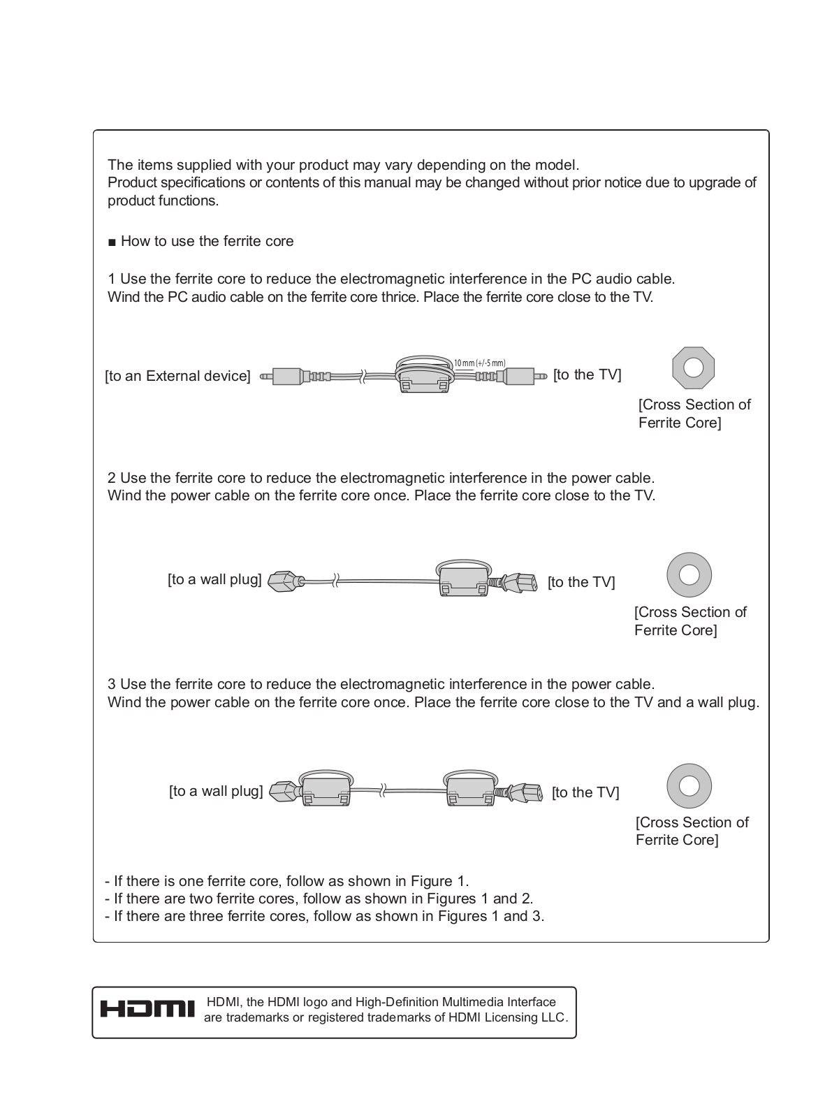
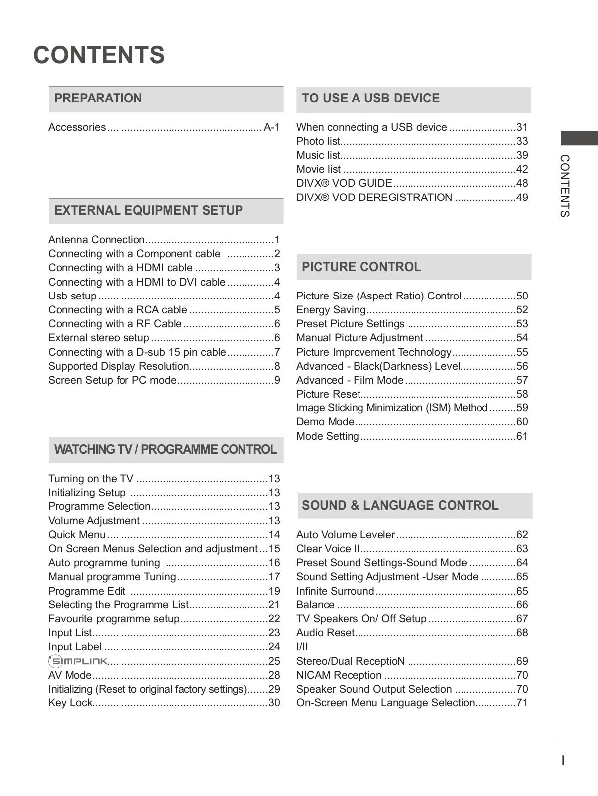
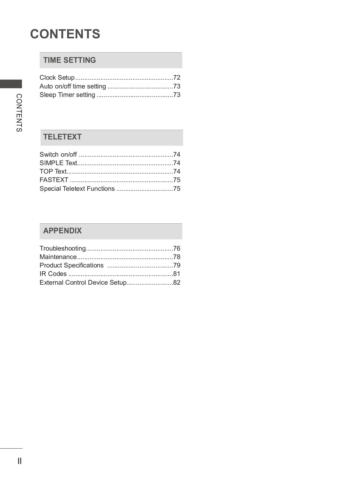
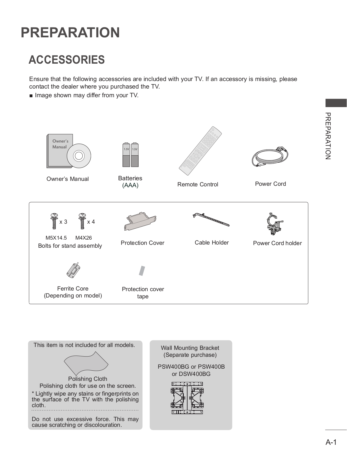
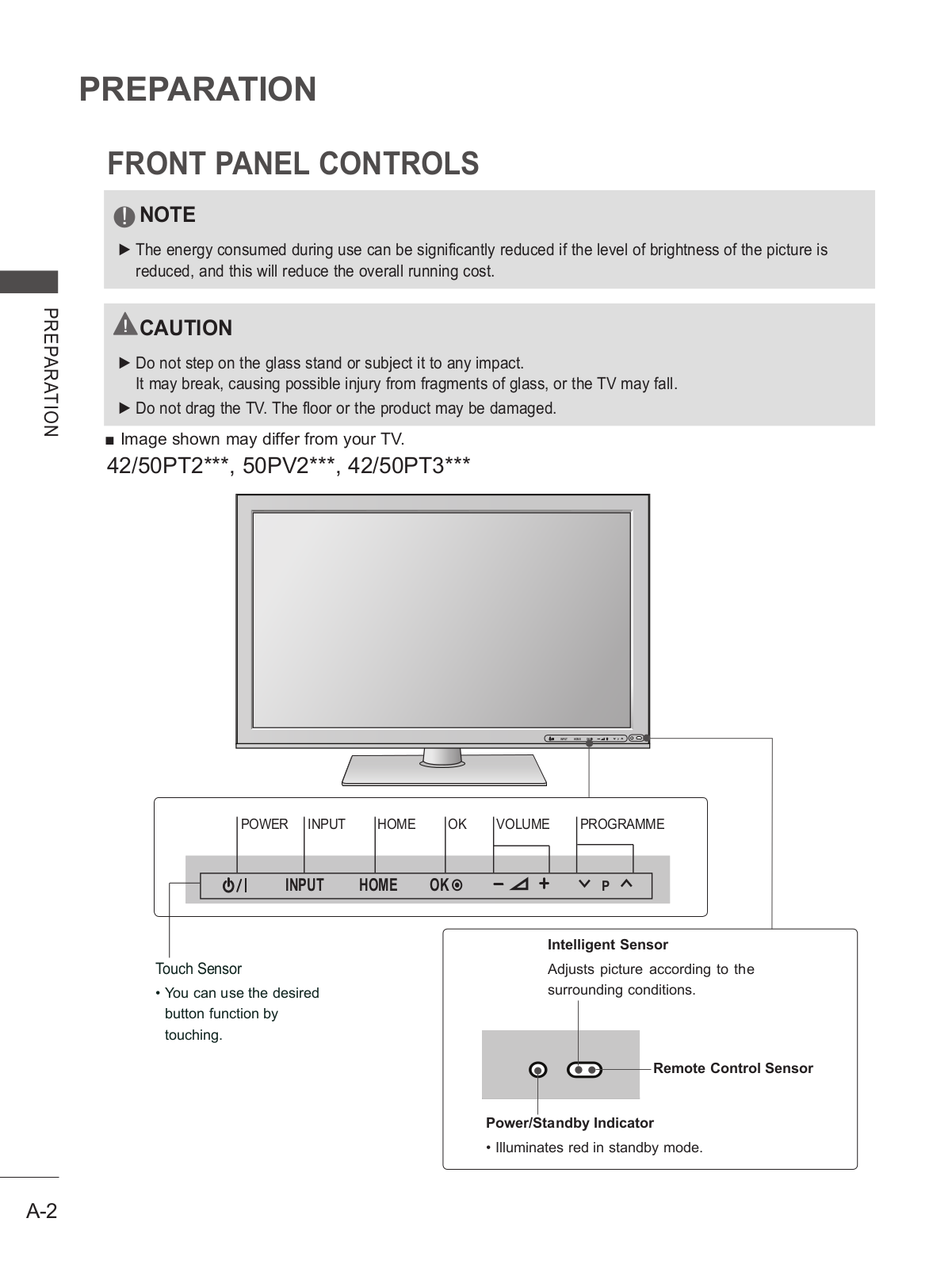
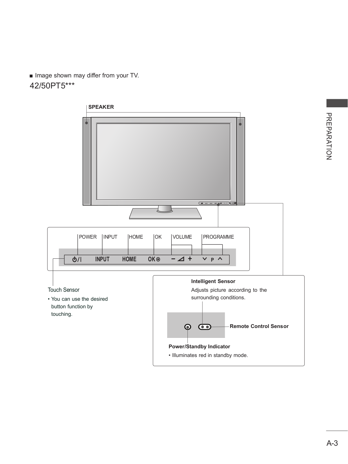
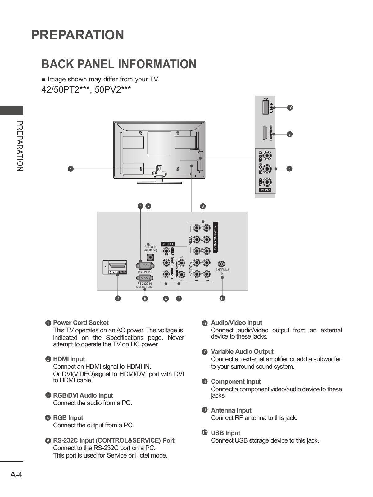
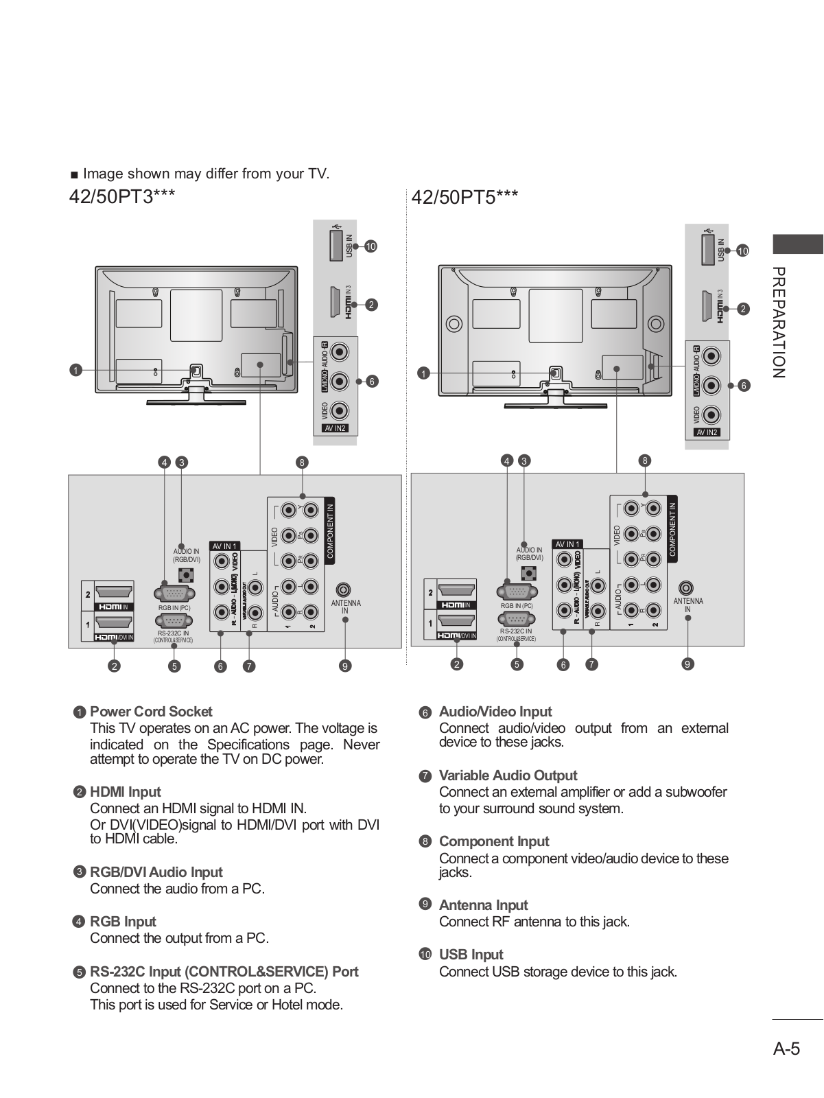
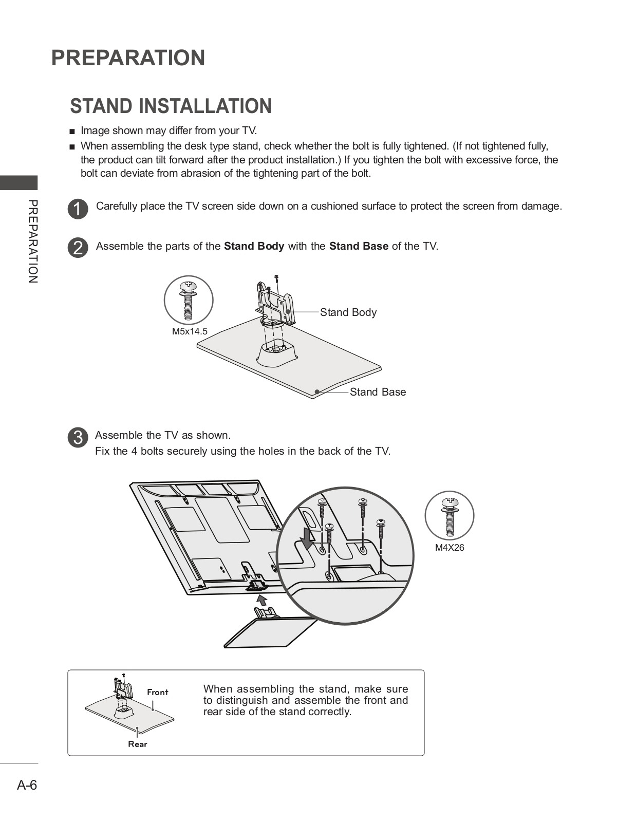
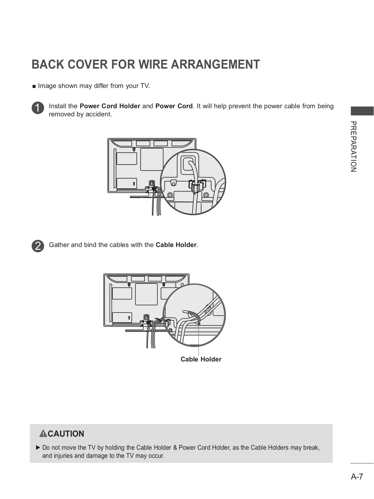
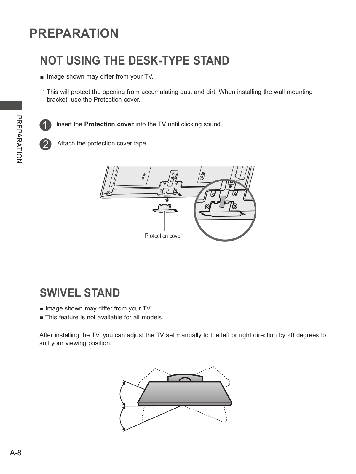
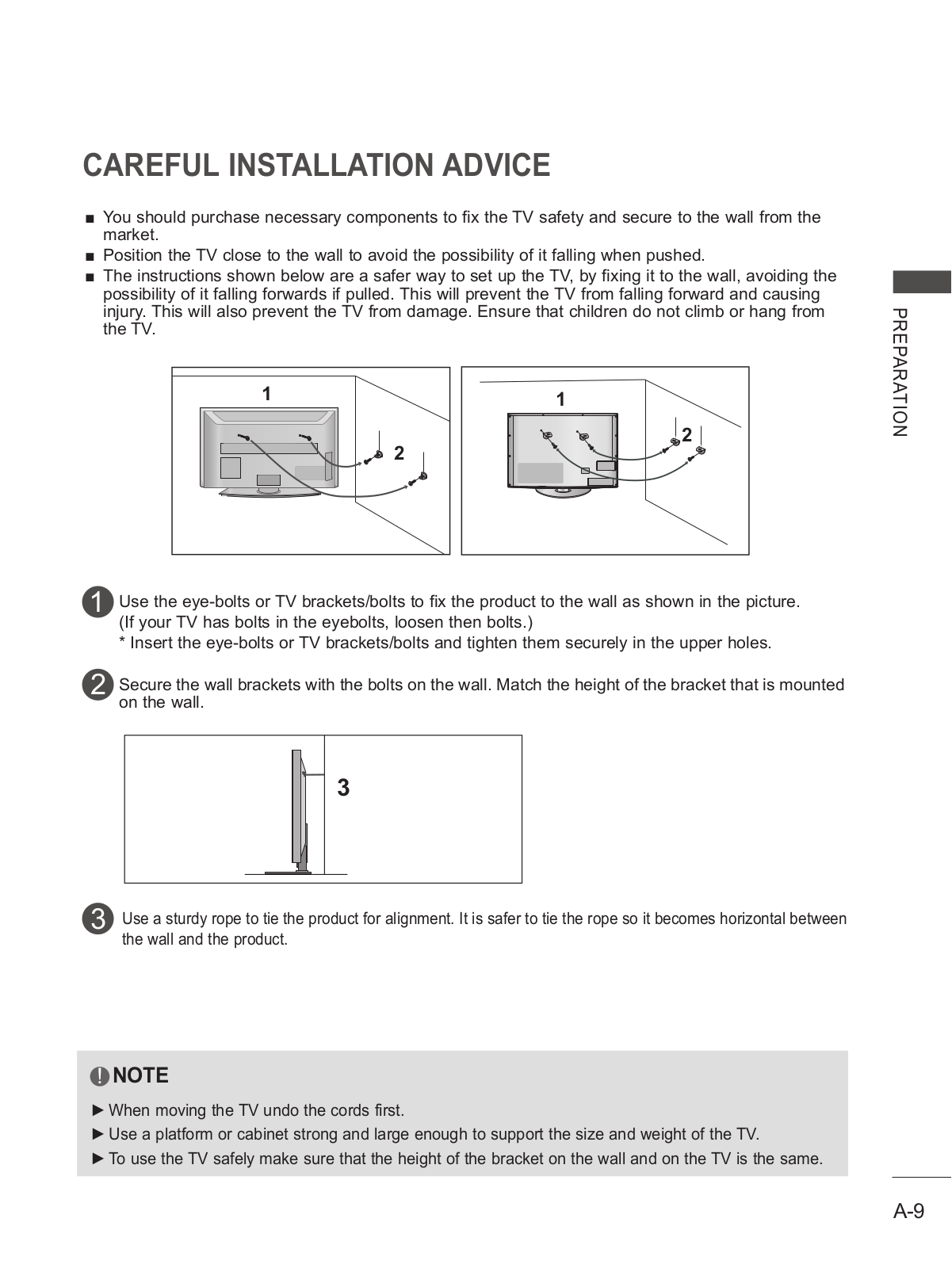
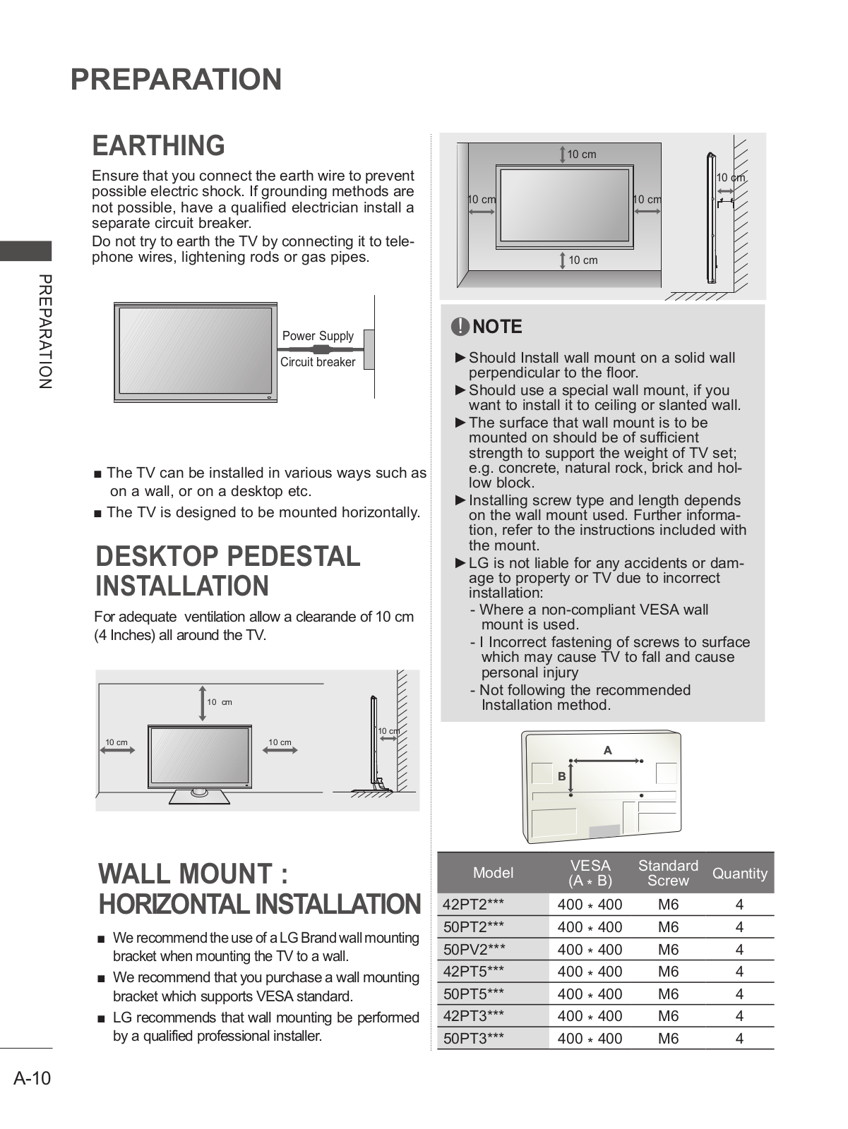
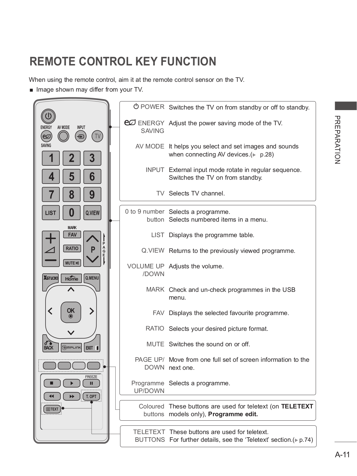
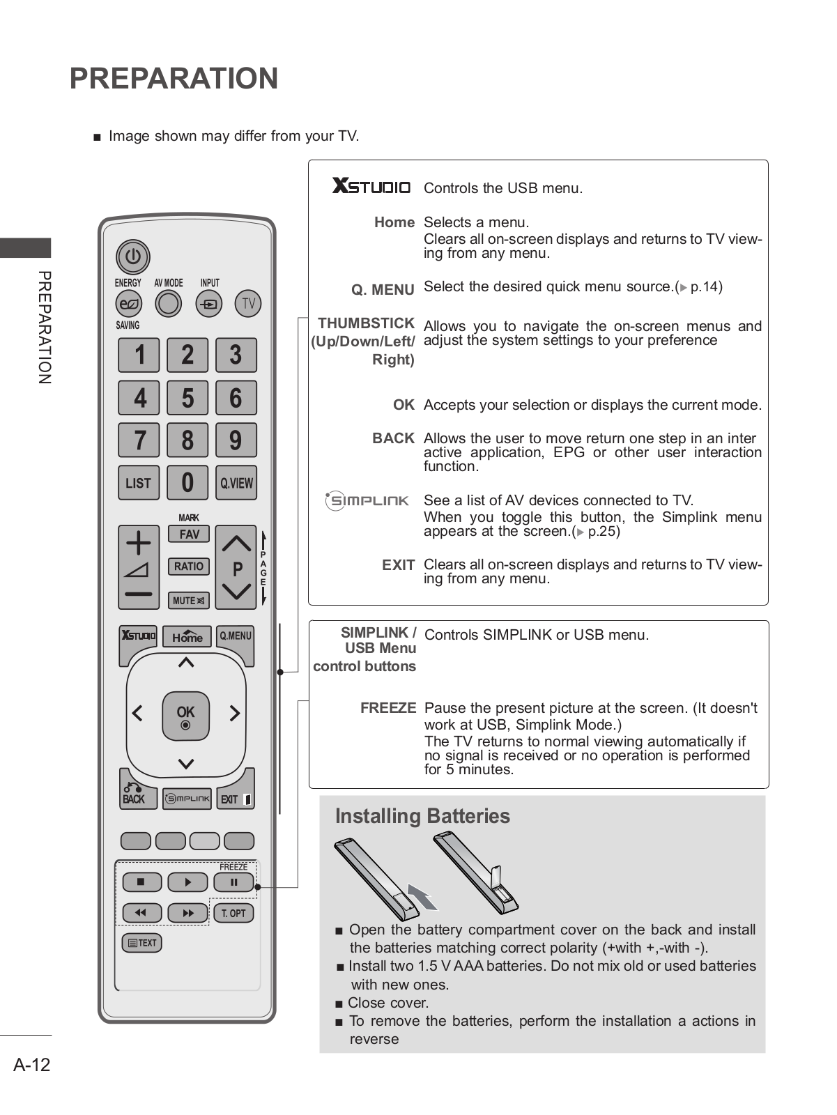
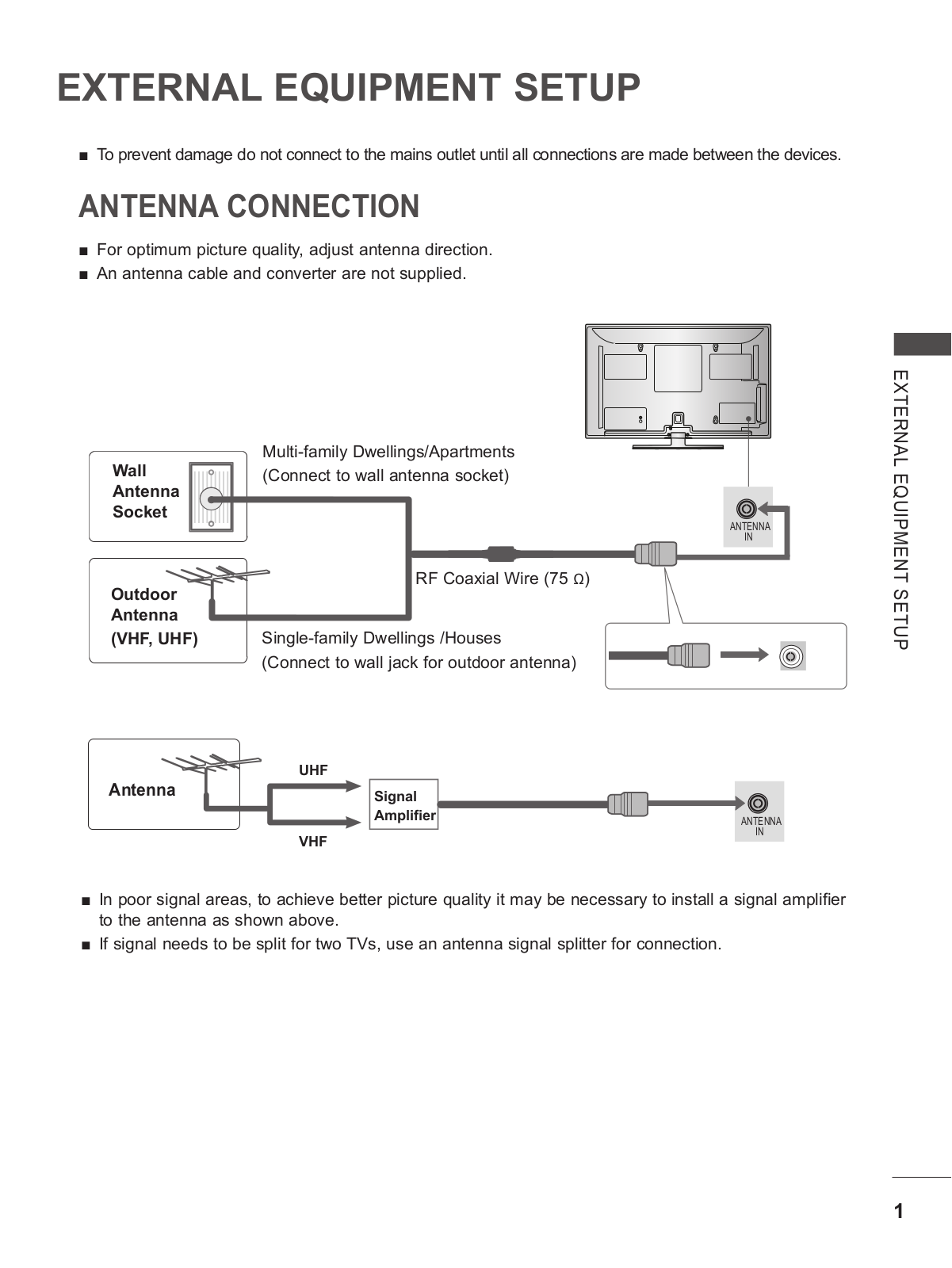
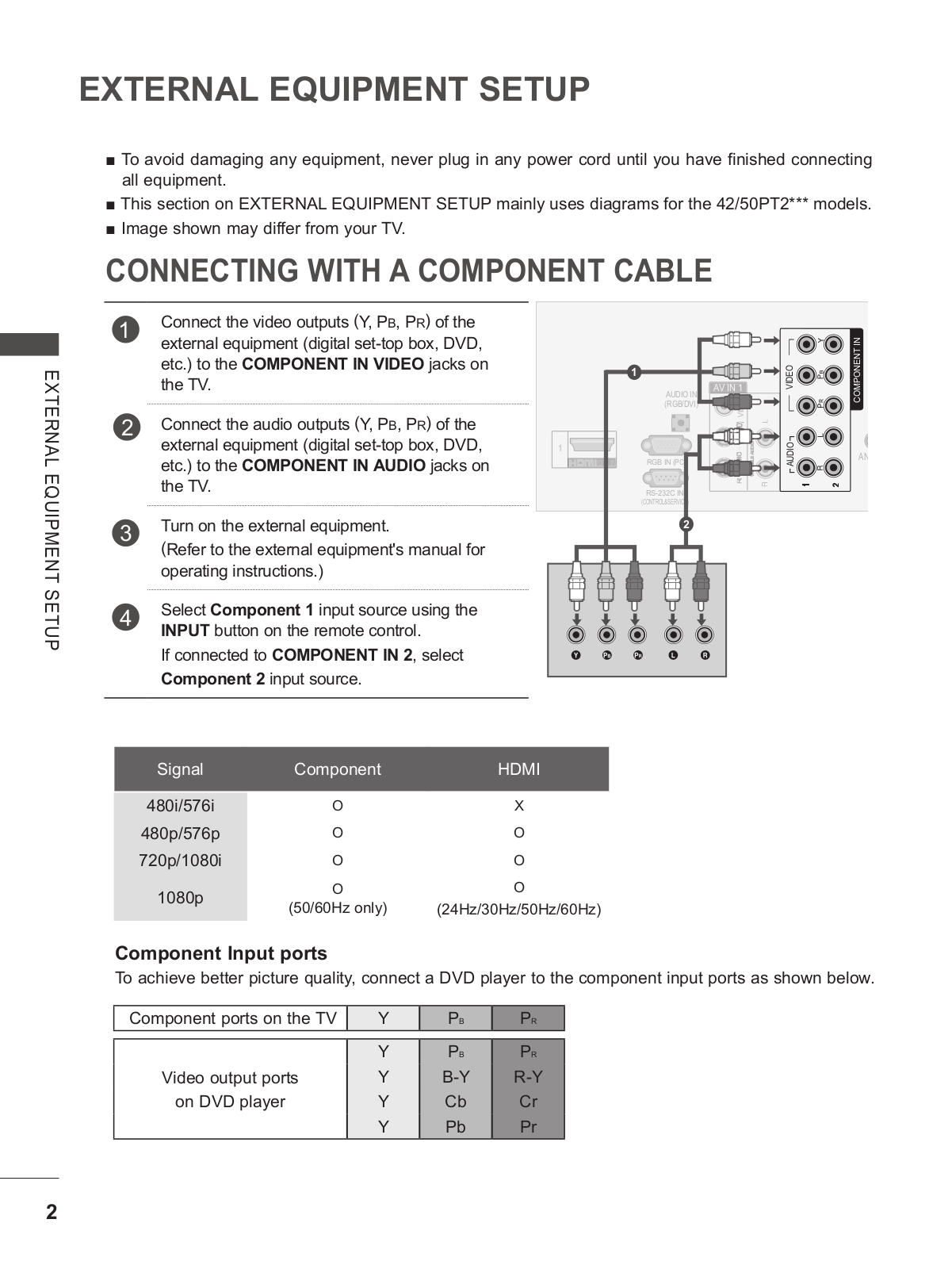
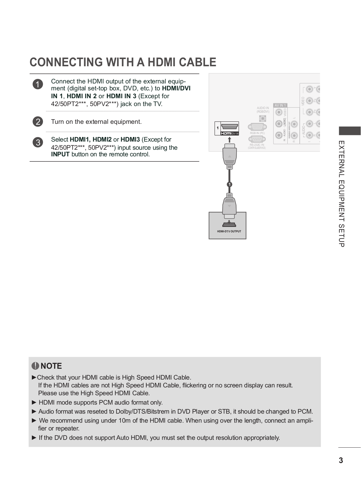
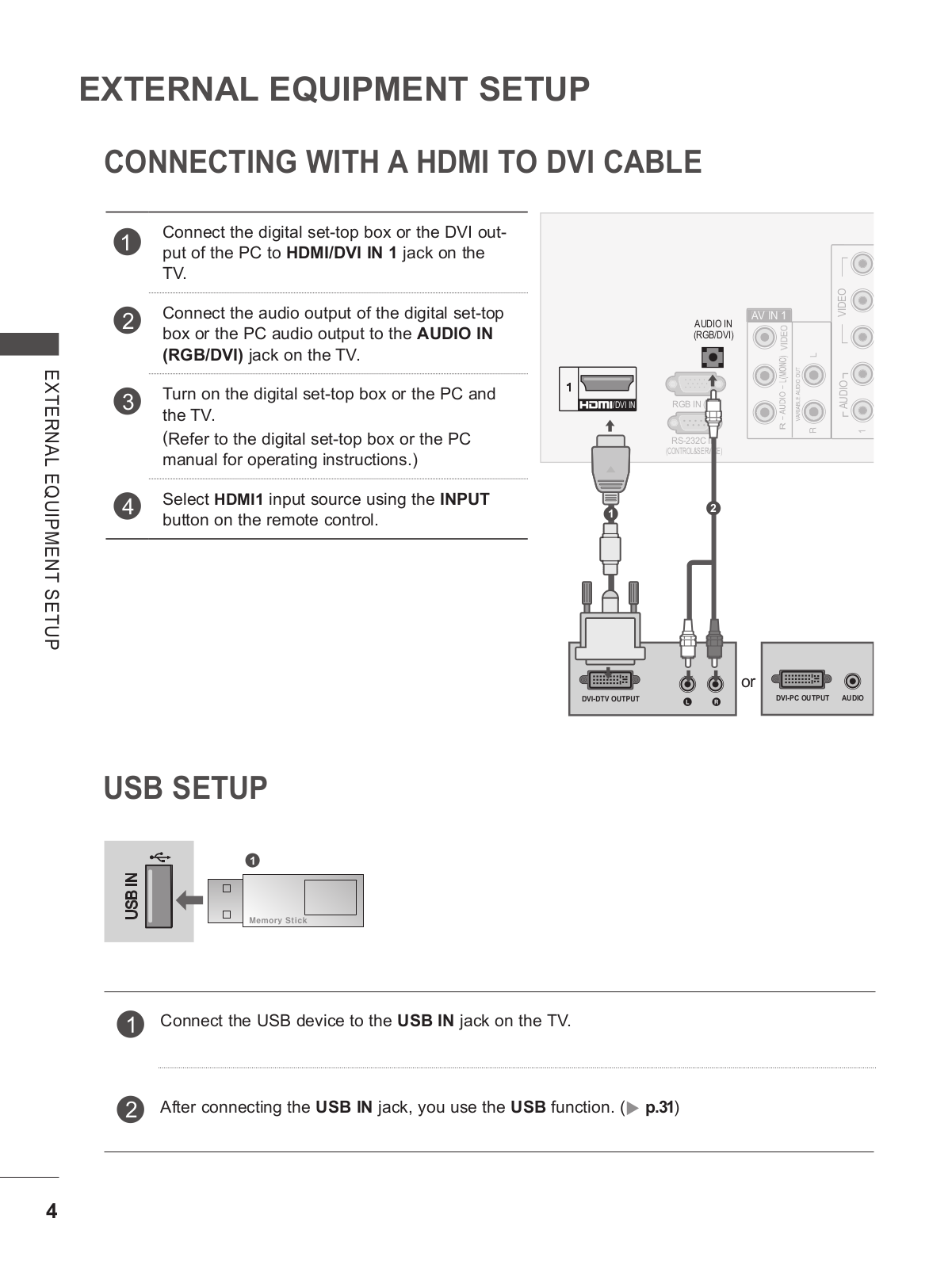
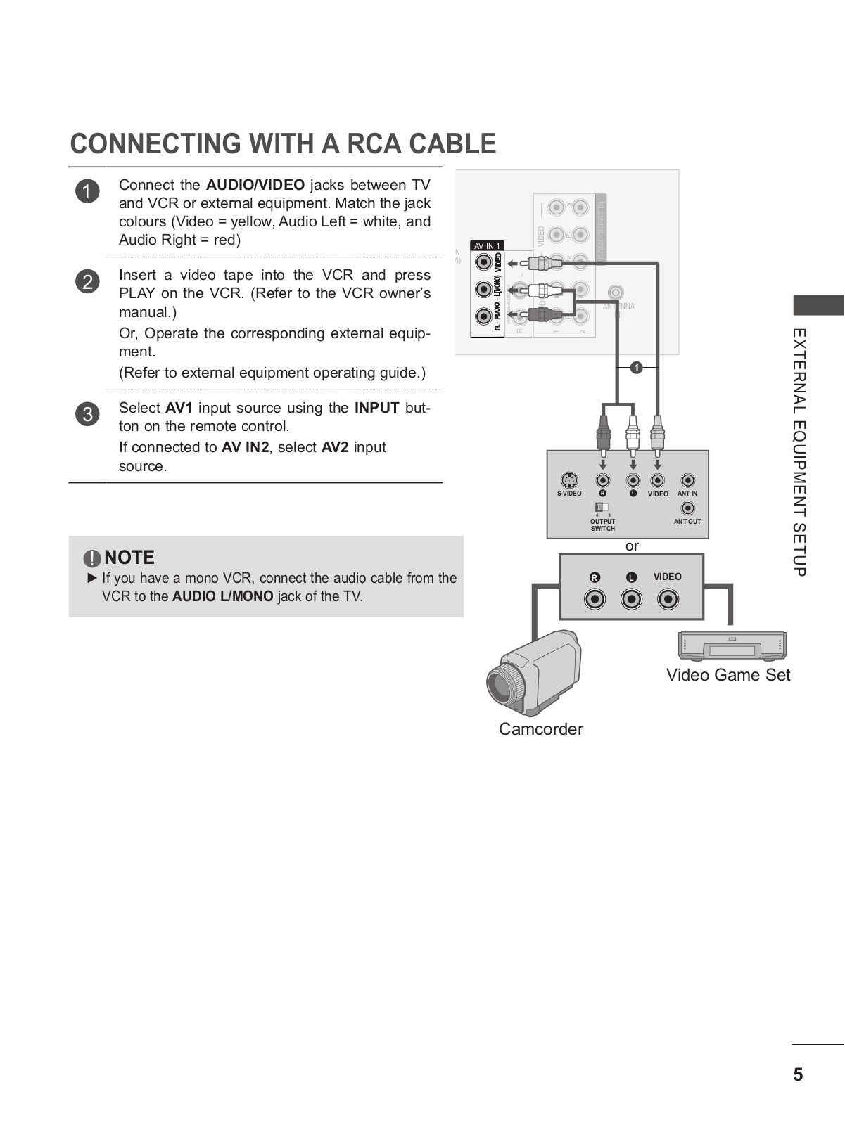
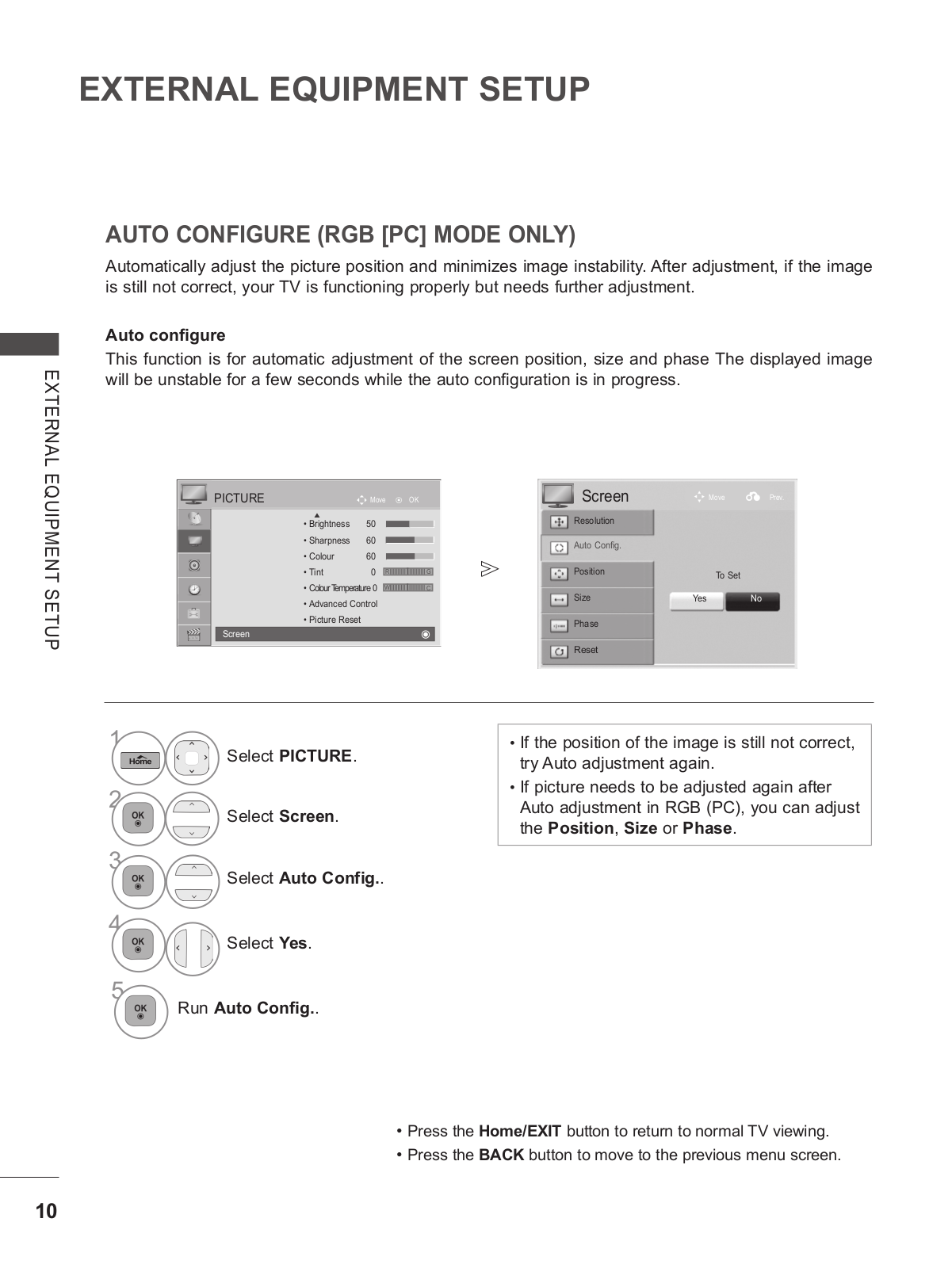
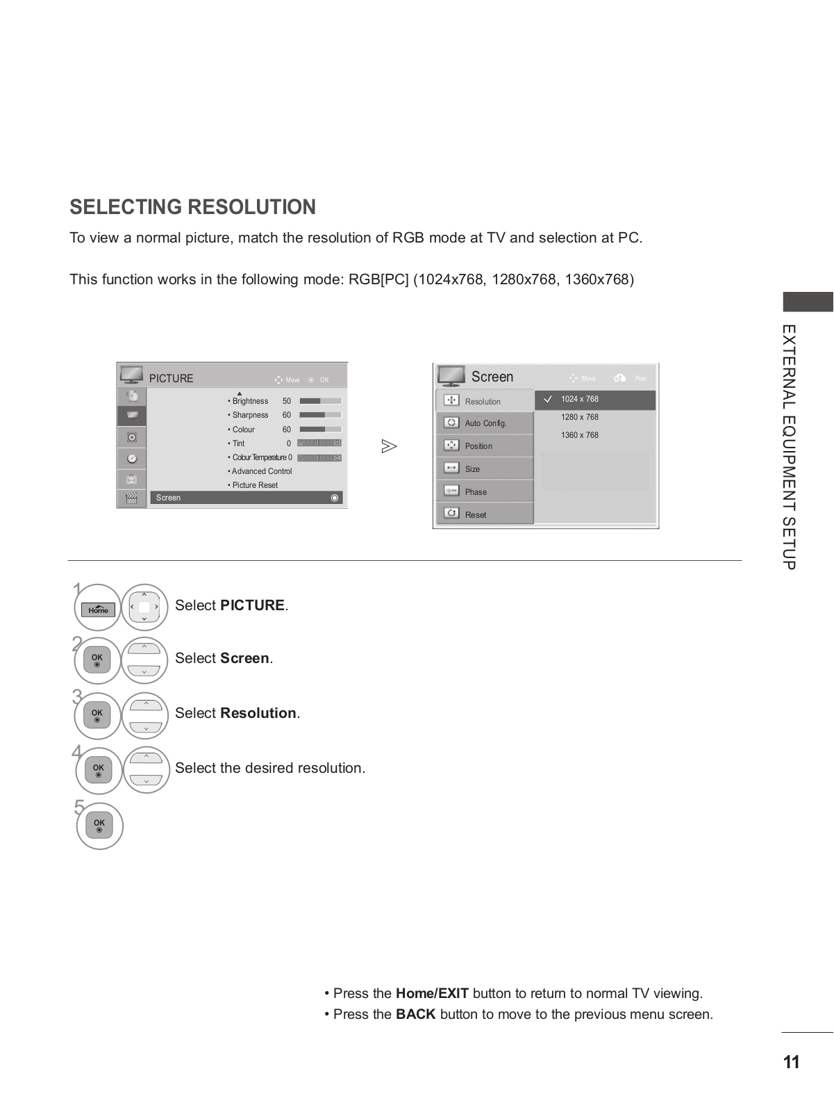
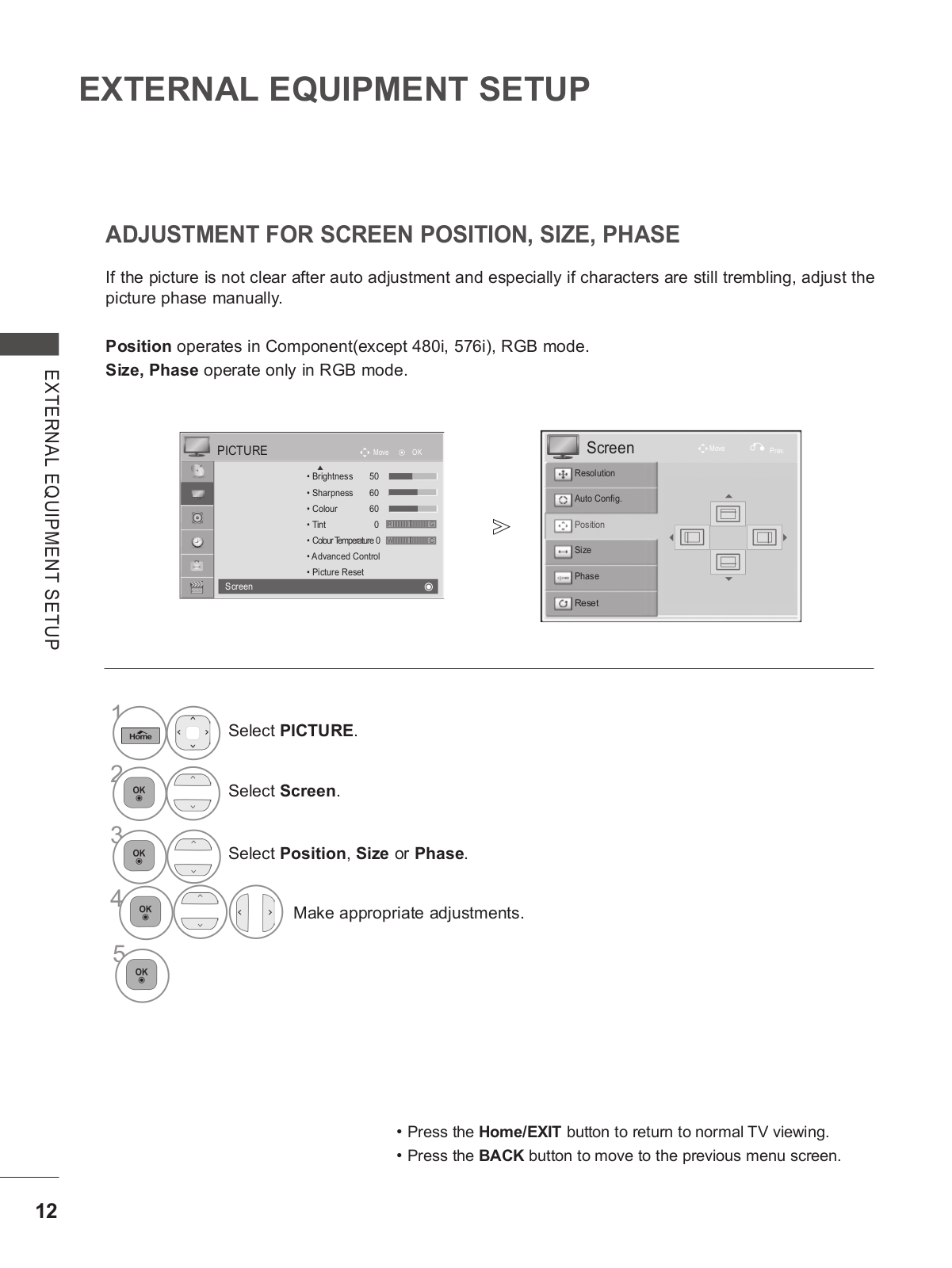
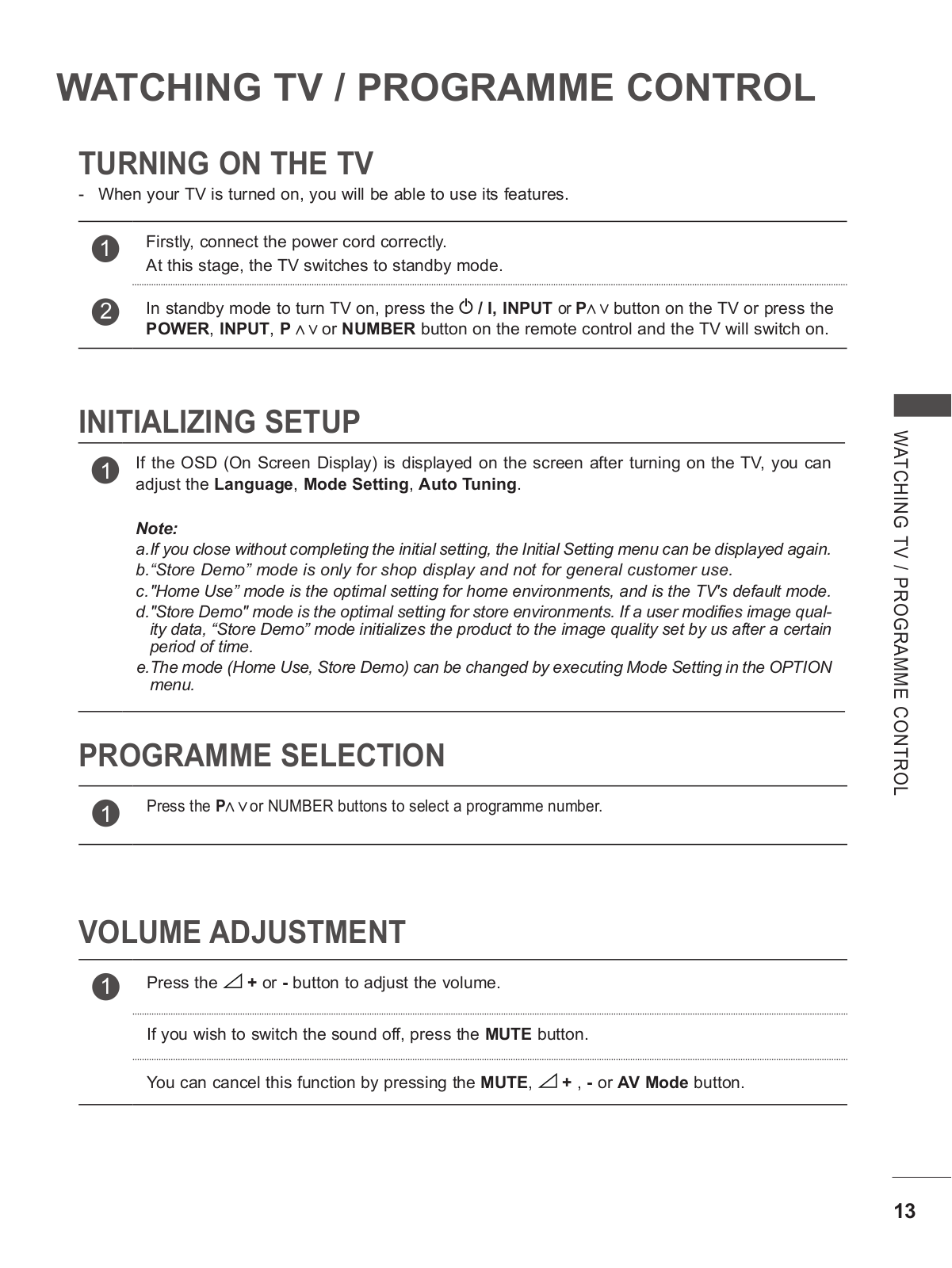
LG 50PT350R, 50PV250R Owner’s Manual
...
LG Owner’s Manual
Download
Specifications and Main Features
Frequently Asked Questions
User Manual
Download
Loading...
+
76
hidden pages
Unhide
You need points to download manuals.
1 point = 1 manual.
You can buy points or you can get point for every manual you upload.
Buy points
Upload your manuals
 Loading...