How it Works
Log In / Sign Up
Buy Points
How it Works
FAQ
Contact Us
Questions and Suggestions
Users
LG
Loading...
#
47LY761H-ZA
2
47LY9
29
47LY90
47LY95
13
47LY95-ZA
47LY96
2
47LY960H
2
47LY960H-TA
47LY970H
2
47LY9 Series
2
47LZ9600
2
47LZ9600-TA
47S18
47S19
47SL8
26
47SL80
9
47SL8000
15
47SL8000-ZB
2
47SL8001
47SL80 Series
47SL80YD
5
47SL80YD-CA
47SL80YD-SA
47SL80YR
6
47SL82UA
47SL8500
13
47SL8500-ZA
2
47SL85-UA
47SL8 series
2
47SL9
8
47SL90
7
47SL9000
7
47SL9000-ZA
47SL90QD
8
47SL90QD-SA
2
47SL90QR
4
47SL90QR-LA
47SL90QR-MA
47SL90 Series
47SL90TA
47SL90-UA
2
47SL9500
6
47SL9500-ZB
47SL9 series
3
47TS30MF
47TS30MF-B
4
47TS50MF
47TS50MF-B
5
47VL10
6
47VL10-BAA
4
47VS10
47VS10MN
47VS10MN-A
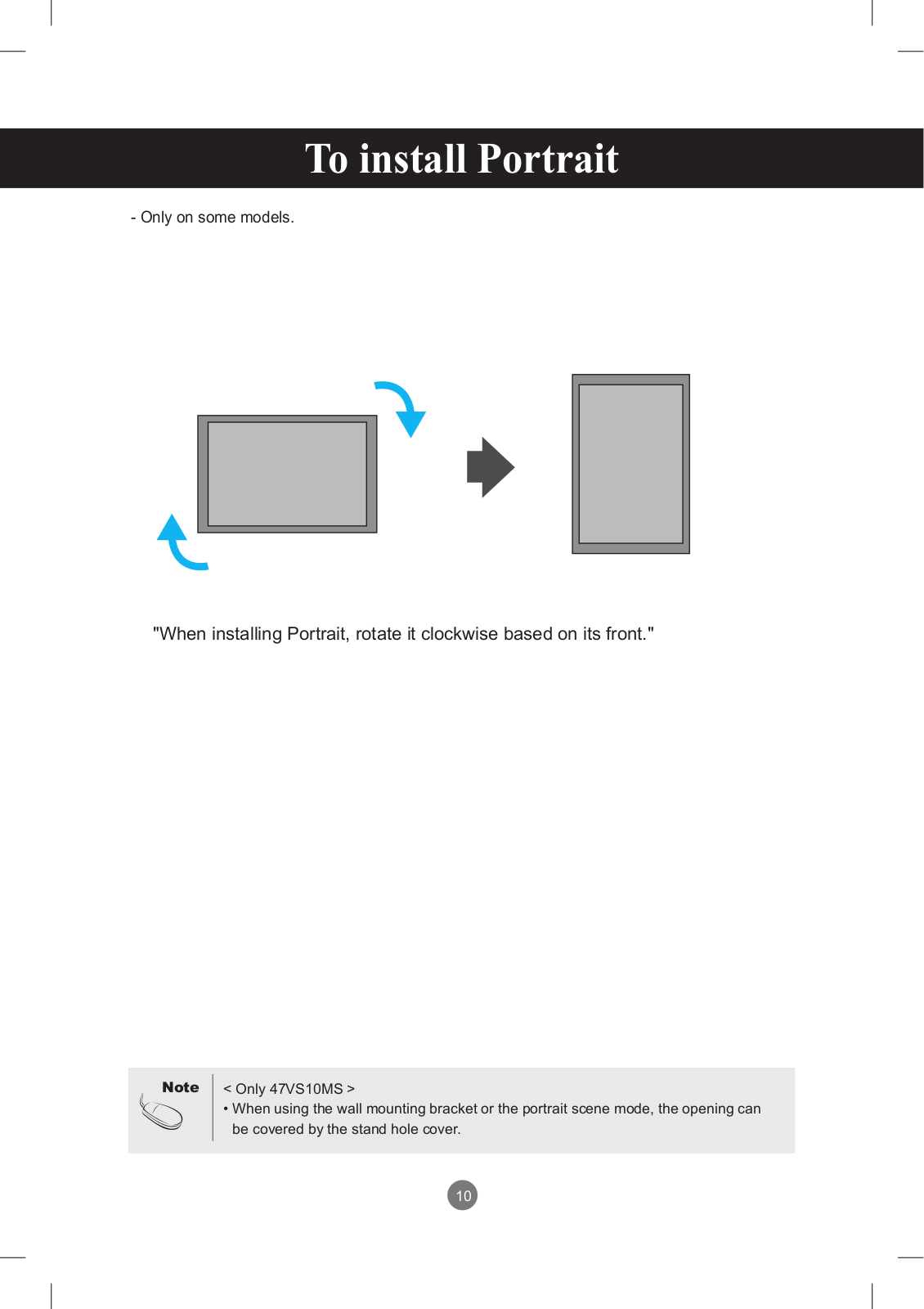
47VS10MS-B
2
47VS20
7
47VS20-BAA
2
47VS20-BAP
47VT30
47VT30MS-B
4
47VX30
47VX30AF
2
47VX30AF-B
2
47VX30AS
3
47VX30AS-B
47VX30MF
3
47VX30MF-B
2
47VX30MS
47WFB
2
47WL10
47WL10MS
3
47WL10MS-B
5
47WL30
47WL30MS
2
47WL30MS-D
3
47WS10
5
47WS10-BAA
5
47WS10-BAP
47WS50
47WS50BS
4
47WS50BS-B
4
47WS50MS
4
47WS50MS-B
8
47WS50MW
2
47WS50MW-B
47WT30MS
2
47WT30MS-B
47WV30
7
47WV30-BAA
9
47WV30-BAAL
7
47WV30 - BAAM
6
47WV30BR
8
47WV30BR-B
5
47WV30BS
8
47WV30BS-B
6
47WV30BS-BL
2
47WV30MS
6
47WV30MS-B
4
47WV50
47WV50BR
47WV50BR-B
5
Loading...
Loading...
Nothing found
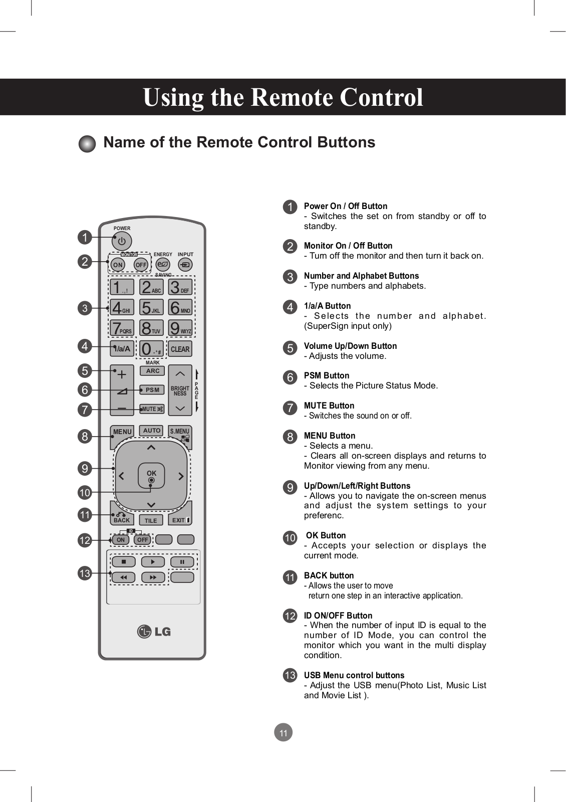
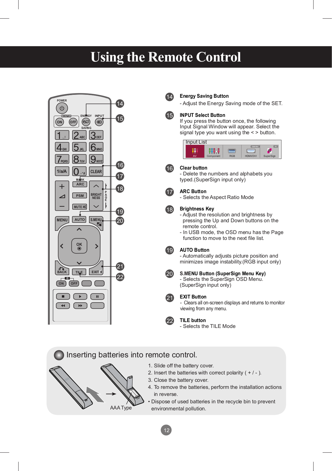
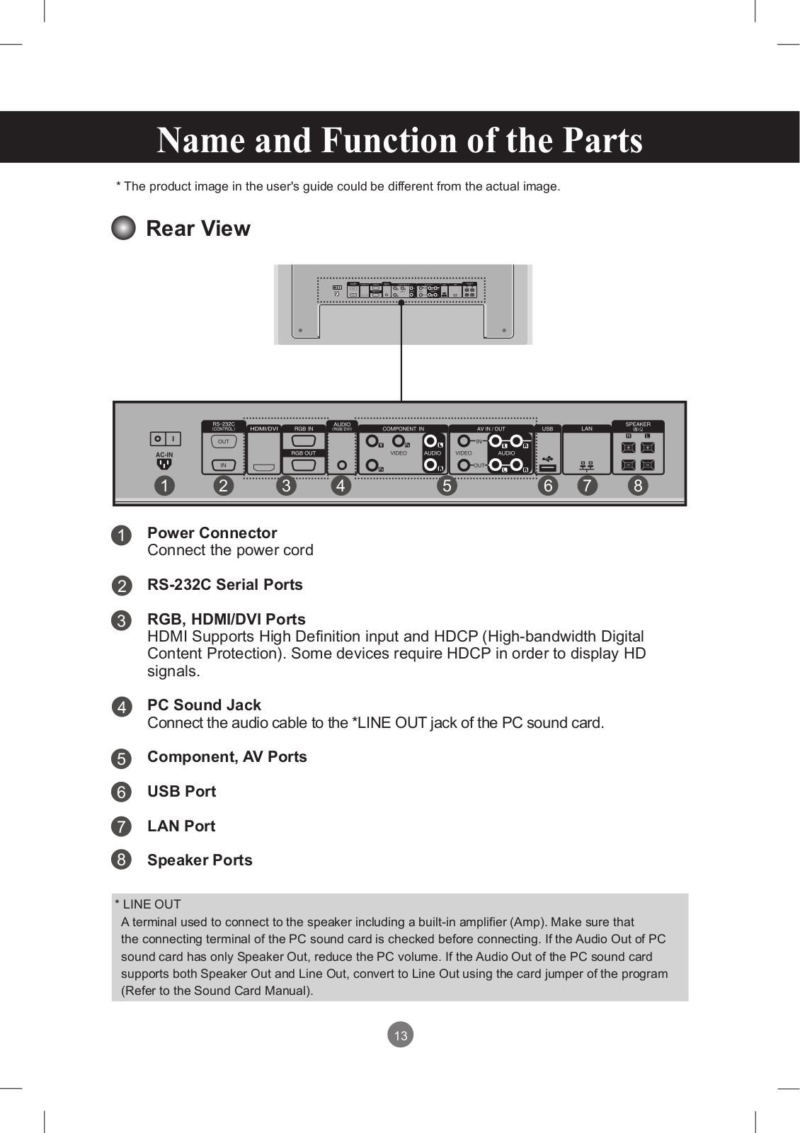
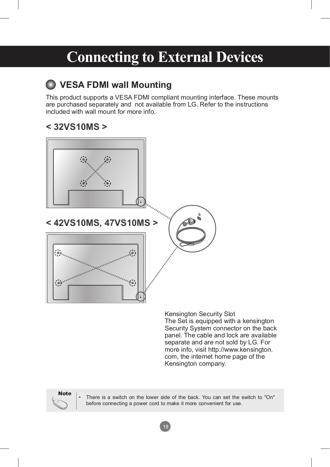
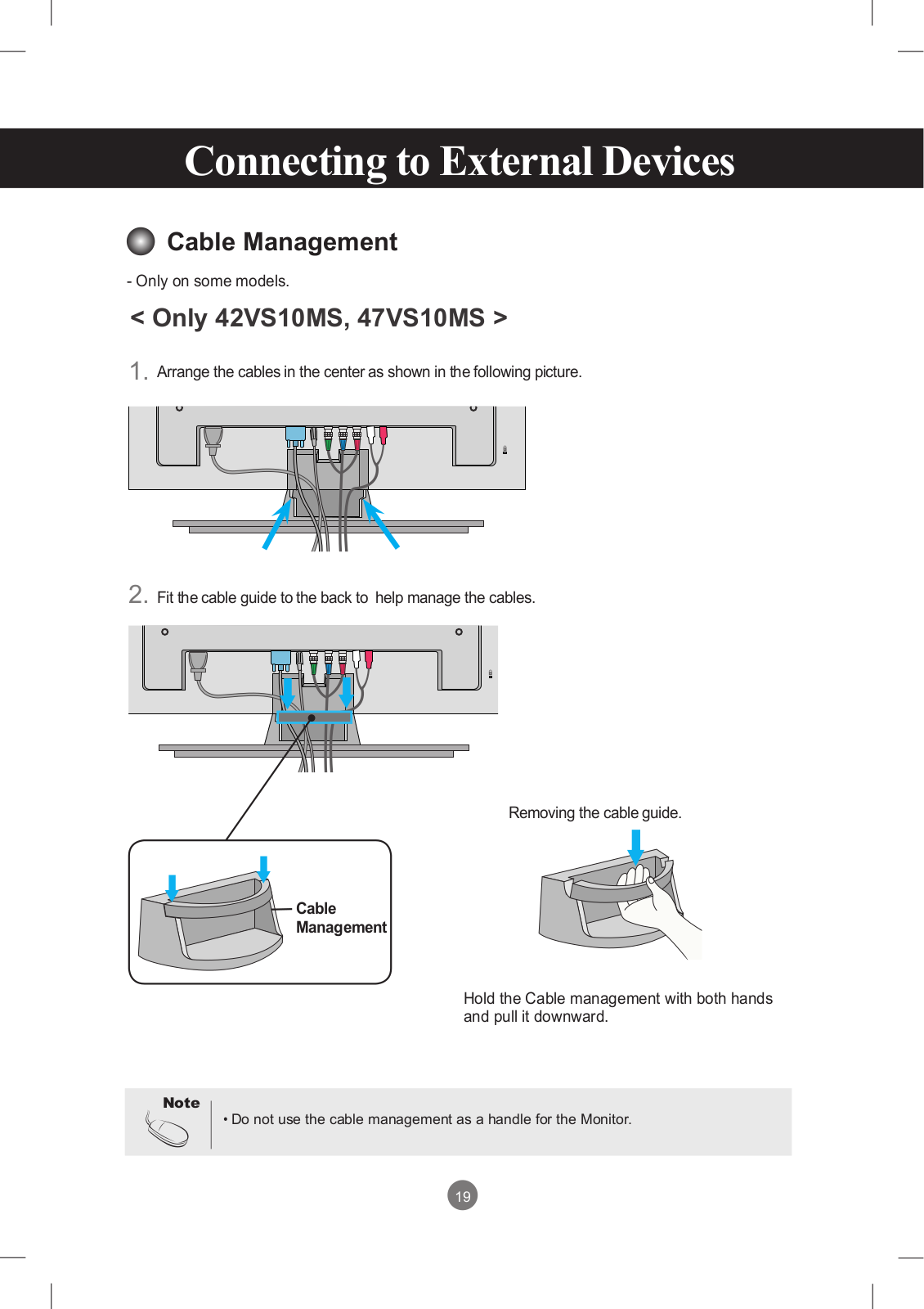
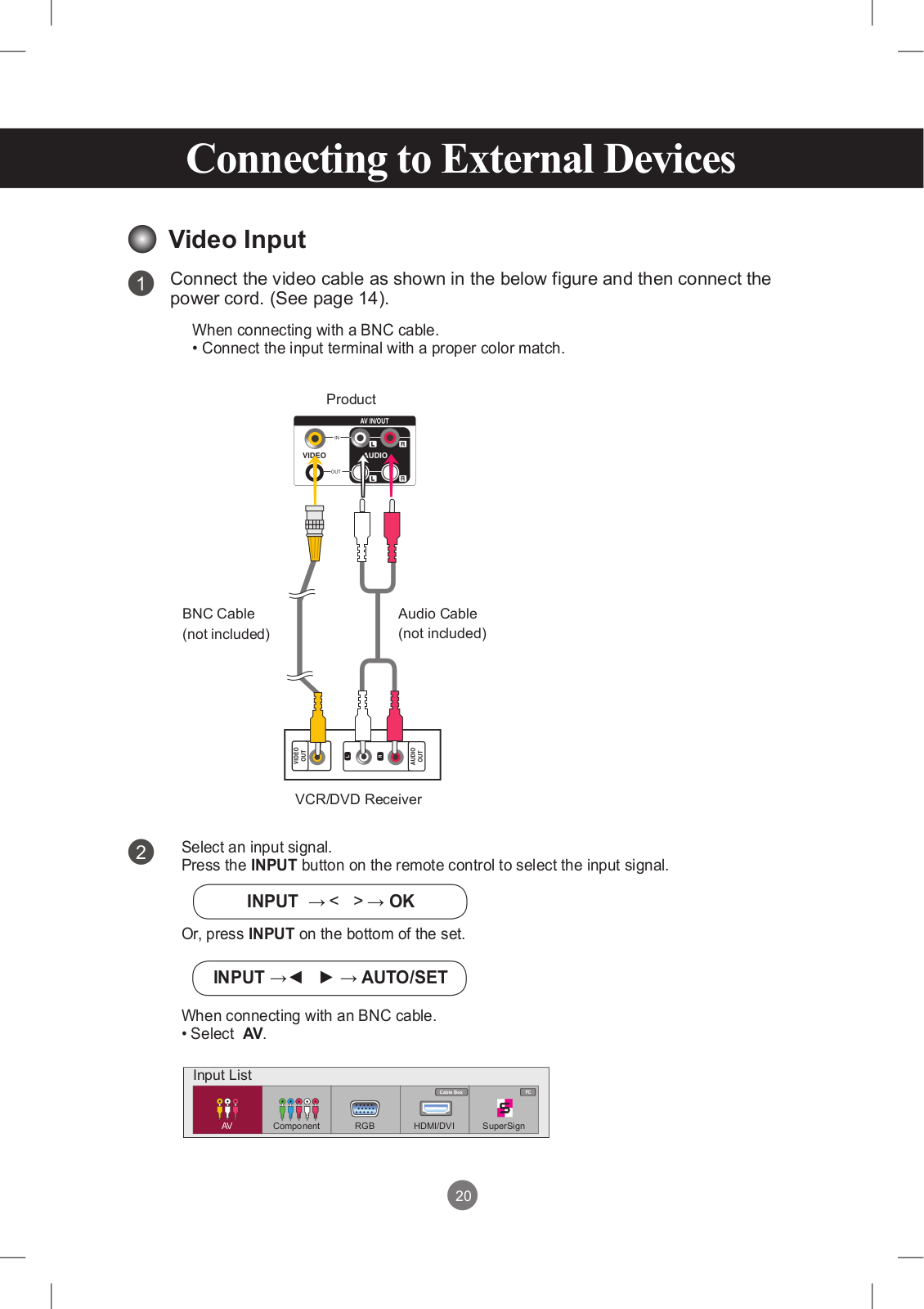
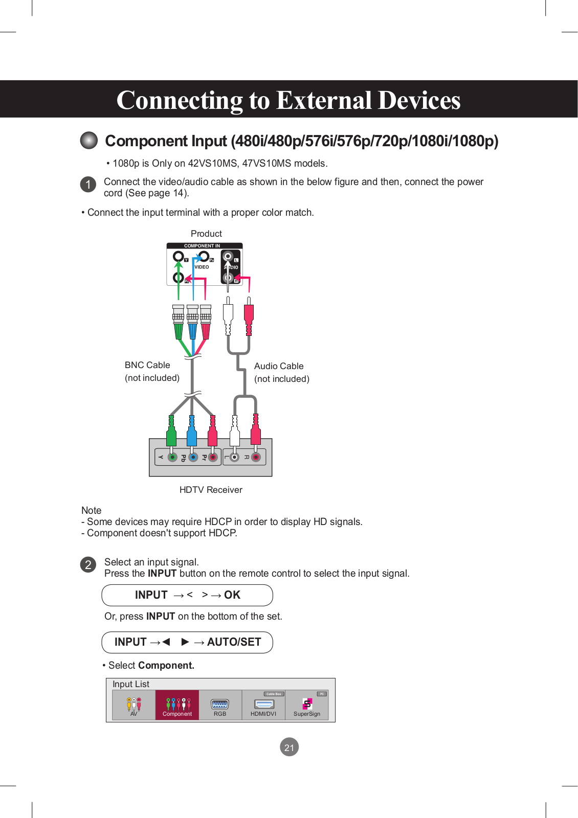
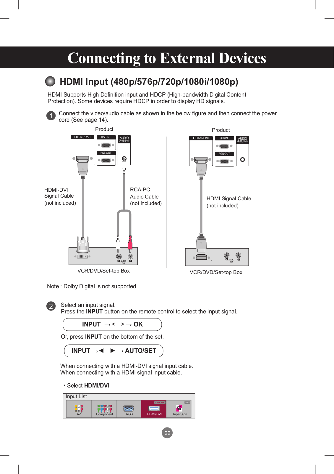
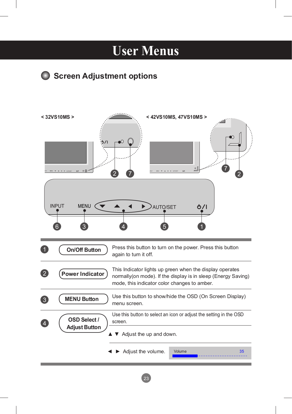
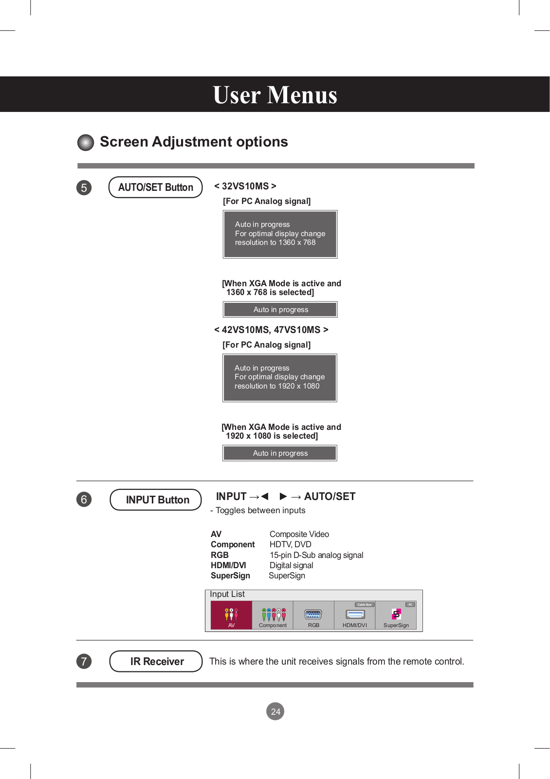
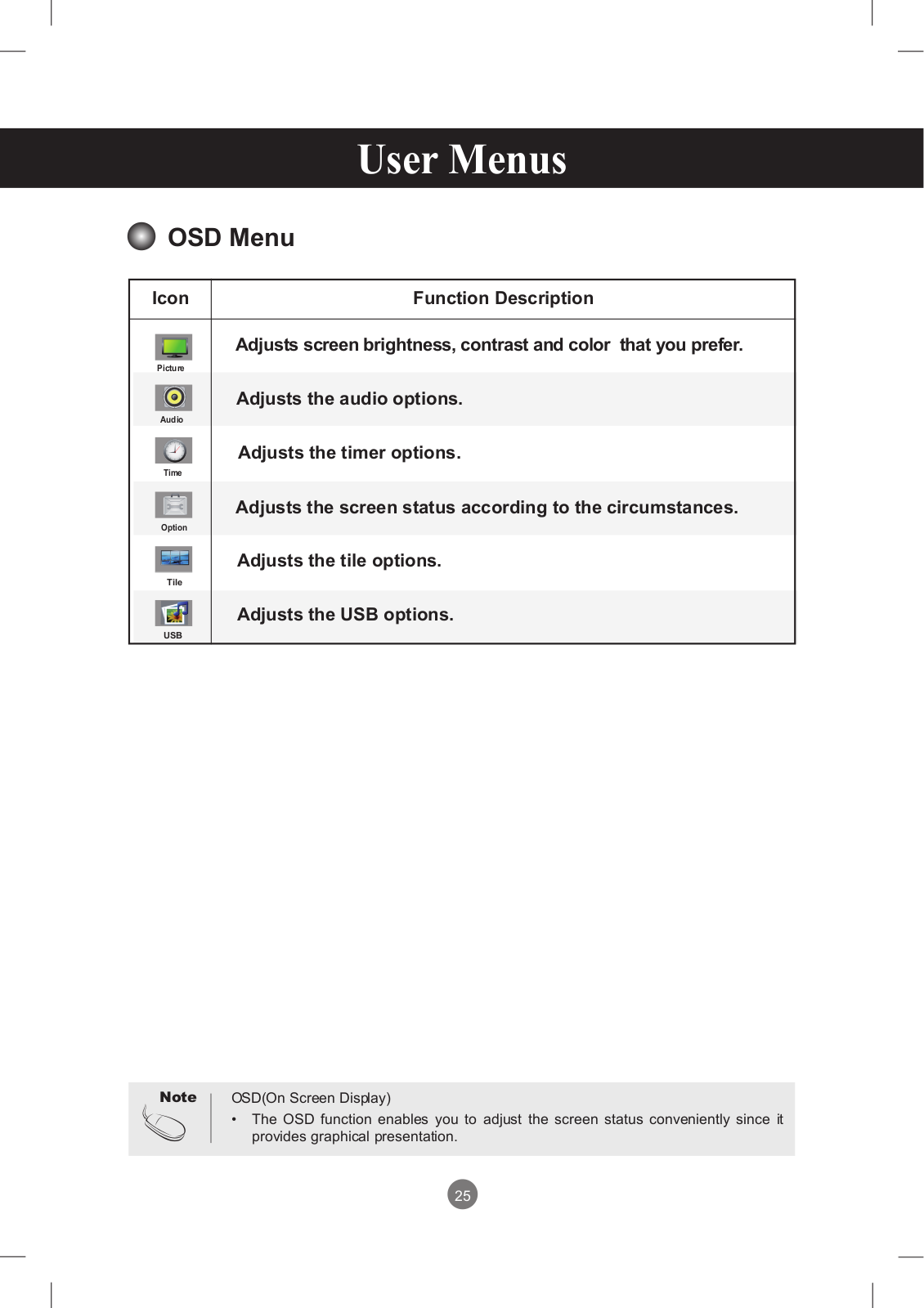
47VS10
User Manual
95 pgs
14.62 Mb
0
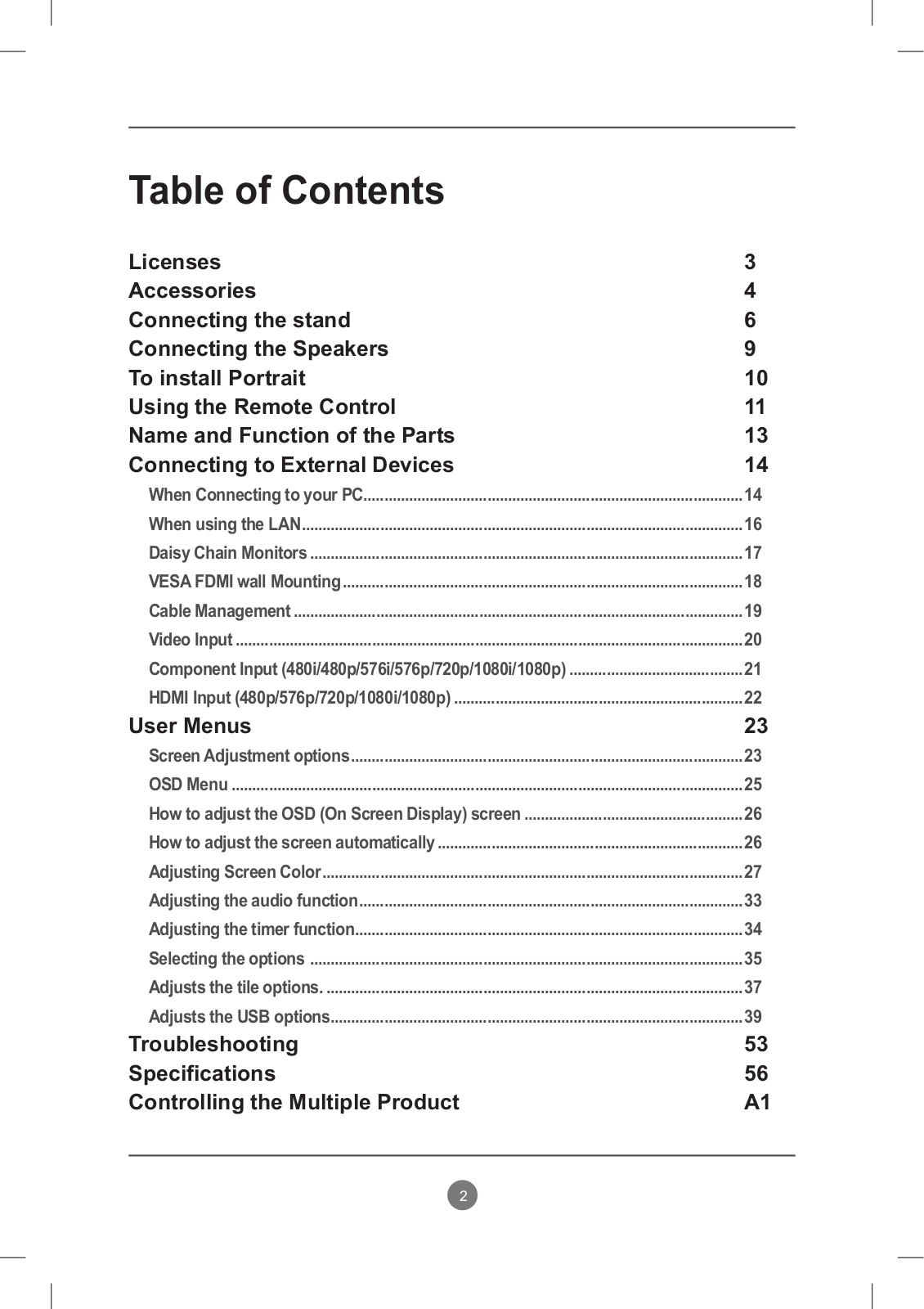
Table of contents
Loading...
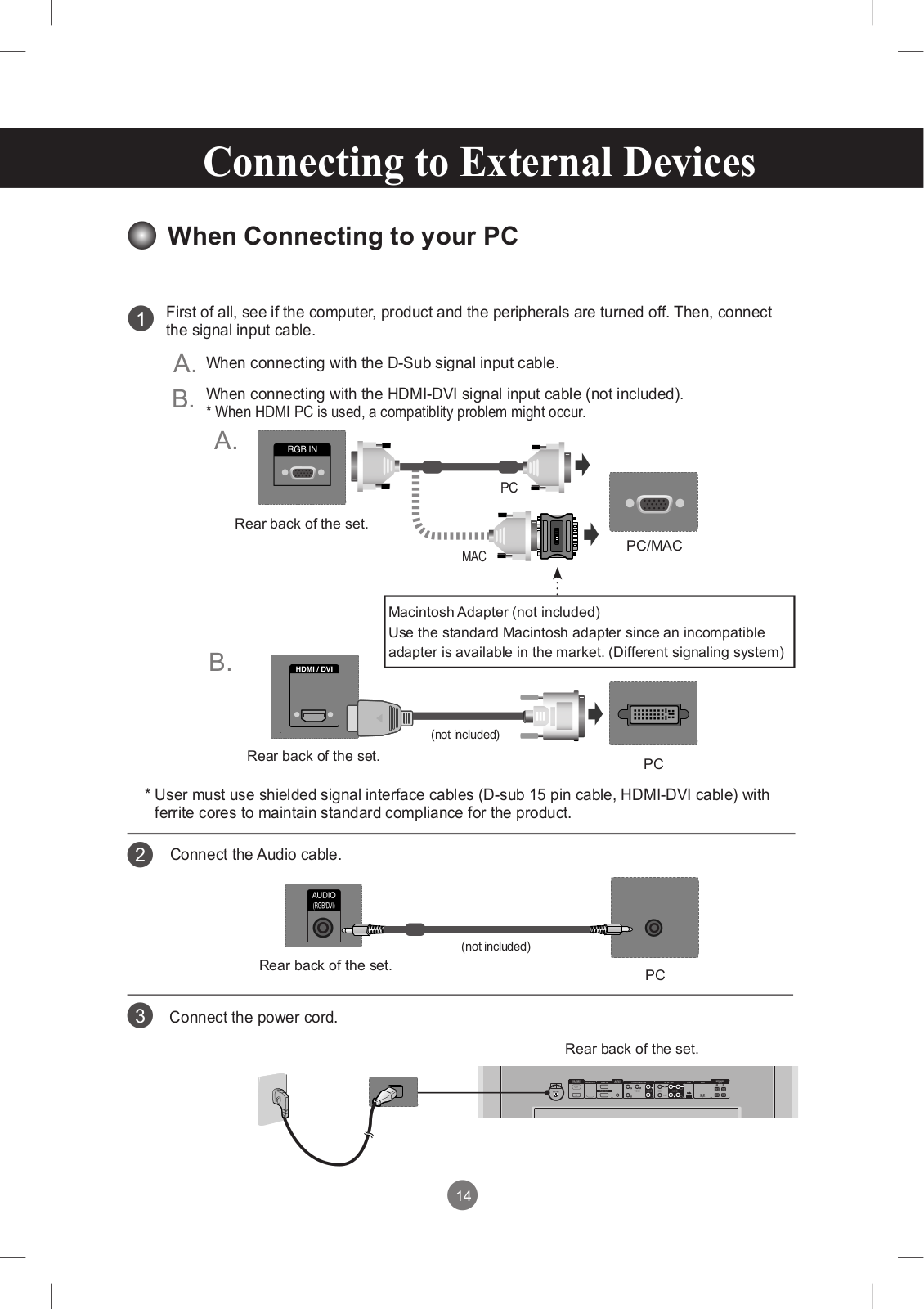
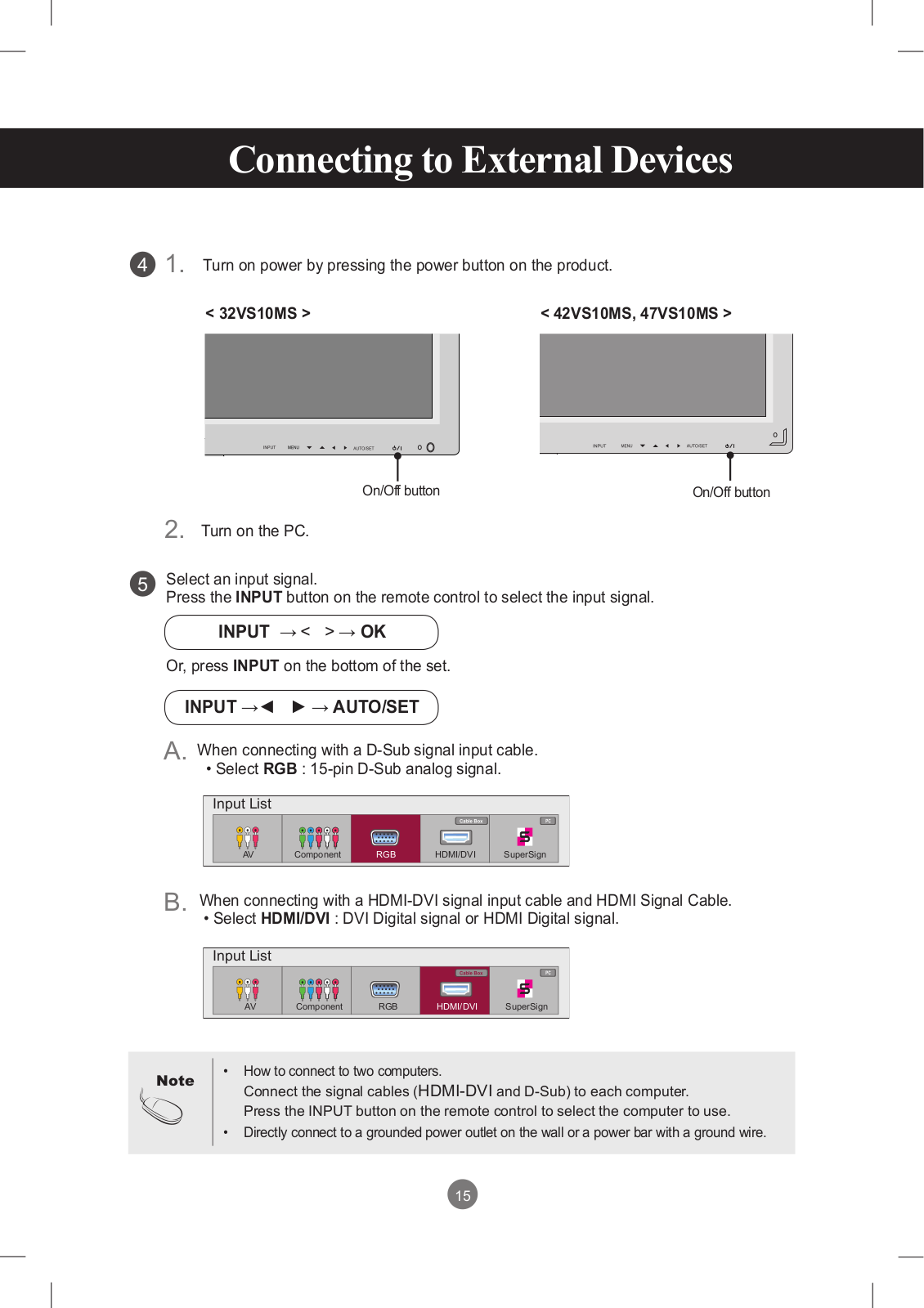
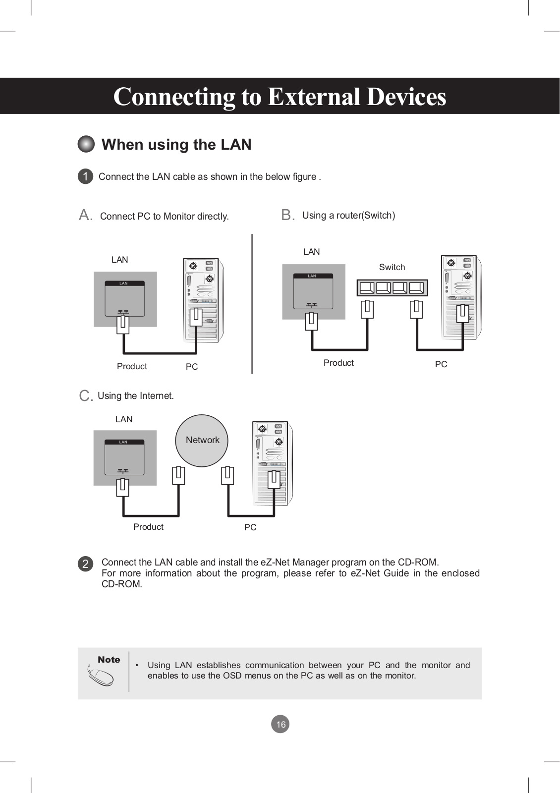
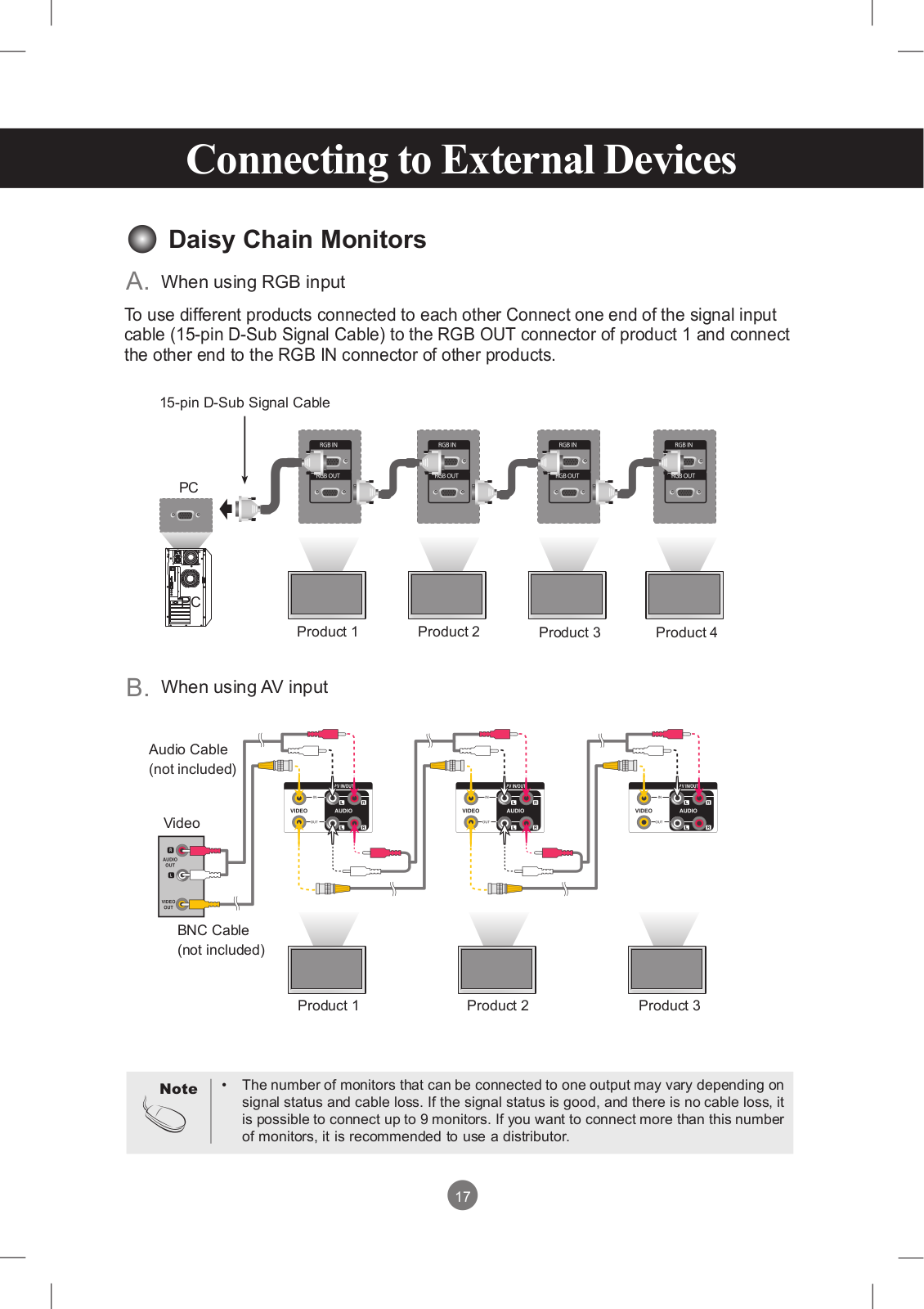
LG 47VS10 User Manual
...
LG User Manual
Download
Specifications and Main Features
Frequently Asked Questions
User Manual
Download
Loading...
+
hidden pages
Unhide
You need points to download manuals.
1 point = 1 manual.
You can buy points or you can get point for every manual you upload.
Buy points
Upload your manuals
 Loading...