

Page 1

OWNER’S MANUAL
LCD TV MODELS
1199LLHH22******
2222LLHH22******
2266LLHH22******
3322LLHH22******
3377LLHH22******
4422LLHH22******
3322LLFF22******
4422LLFF22******
3322LLHH33******
3377LLHH33******
4422LLHH33******
4477LLHH33******
1199LLUU55******
2222LLUU55******
2266LLUU55******
LCD TV
Please read this manual carefully before operating
your TV.
Retain it for future reference.
Record the model number and serial number of the
TV.
Refer to the label on the back cover and quote this
information.
To your dealer when requiring any service.
ENGLISH
3377LLHH55******
4422LLHH55******
4477LLHH55******
5555LLHH55******
3322LLHH66******
4422LLHH66******
3322LLHH77******
3377LLHH77******
4422LLHH77******
4477LLHH77******
3322SSLL88******
4422SSLL88******
4477SSLL88******
5555SSLL88******
LED LCD TV MODELS
4422LLHH99** ** **
4477LLHH99** ** **
4422SSLL99** ** **
4477SSLL99** ** **
LED LCD TV
Page 2

Wall Mounting Bracket(Separate purchase)
RW120
(19/22LH2***,
19/22LU5
***
)
RW230
(26/32LH2***, 32LF2***
26LU5
***, 32LH3***,
32LH6***, 32LH7***,
32SL8***
)
AW-47LG30M
(32/37/42LH2***, 32/42LF2***,
32/37/42/47LH3***,
37/42/47LH5***, 32/42LH6***,
32/37/42/47LH7***, 42/47LH9***,
32/42/47SL8***, 42/47SL9***)
12mm
12mm
Use screws 12mm(+0.5/-0.5) long on the SET assembly side.(Separate purchase)
(
Only 42/47LH7***, 42/47SL8***, 42/47SL9***
)
AW-55LH40M
(55LH5***, 55SL8***)
Set assembly side
(without guide spacer)
Set assembly side
(with guide spacer)
Guide spacer
HDMI, the HDMI logo and High-Definition Multimedia
Interface are trademarks or registered trademarks of
HDMI Licensing LLC.
Only 32/42/47/55SL8***
Cable management
clip
(Refer to p.25)
Protection Cover
(Refer to p.22)
x 8
Bolts for stand
assembly
(Refer to p.20)
(Except 55SL8***)
Cable Holder
(Refer to p.25)
Only 42/47SL9***
Bolts for stand assembly
(Refer to p.20)
Cable Holder
(Refer to p.25)
20mm
x 3 x 4
16mm
Remote Controls
POWER
AV
MODE
ENERGY SAVING
P
A
G
E
P
FAV
MARK/
MUTE
ON/OFF
123
45
0
6
789
LIST
Q.VIEW
INPUT
MENU
RATIO
Q.MENU
RETURN
OK
TV
OK
TV/INPUT
Batteries
x 2
1-screw for stand fixing
(Refer to p.23)
(Only 26/32/37/42LH2***, 32/42LF2***,
26LU5***, 32/37/42LH3***, 37/42LH5***,
32/42LH6***, 32/37LH7***, 42LH9***)
Cable management
clip
(Refer to p.25)
Page 3

1
ACCESSORIES
ACCESSORIES
Ensure that the following accessories are included with your TV.
If an accessory is missing, please contact the dealer where you purchased the TV.
■
Here shown may be somewhat different from your TV.
Owner’s Manual
Batteries (Except 42/47SL9***)
Remote Controls (Except 42/47SL9***)
Power Cord
Polishing Cloth
Polishing cloth for use on the screen.
This item is not included for all models.
* Lightly wipe any stains or fingerprints on
the surface of the TV with the polishing
cloth.
Do not use excessive force. This may cause
scratching or discolouration.
RARATIO
SLEEPSLEEP
ENERGY SAVING
Cable management clip
(Refer to p.25)
Protection cover
(Refer to p.22)
bolts for stand assembly (Refer to p. 19)
OOnnllyy 1199//2222LLHH22******
Protection cover
(Refer to p.21)
Only 32/37/42/47LH7
***
AV MODEV MODE
ENERGYENERGY SA SAVINGVING
RETURN
MENU
Q.MENU
MARK
MUTEMUTE
POWERPOWER
LISTLIST
Q.VIEWQ.VIEW
RARATIOTIO
FAV
AV MODE
ENERGY SAVING
MUTE
LIST
Q.VIEW
or
Bolts for stand assembly
(Refer to p.18)
Cable Holder
(Refer to p.24)
OO nnllyy 1199 // 2222// 2266 LLUU55
** ****
Bolts for stand assembly
(Refer to p.19)
x 4
OOnnllyy 2266//3322//3377//4422LLHH22******,, 3322//3377//4422//4477LLHH33******,,
3377//4422//4477//5555LLHH55******,, 3322//4422LLHH66******,, 4422//4477LLHH99******
Protection cover
(Refer to p.22)
Cable management clip
(Refer to p.24)
Stand rear cover
(Refer to p.23)
(37LH7
***
only)
x 8
(42LH7
***
only)
x 3 x 4
M4x20 M4x16
M4x20
(32LH7
***
only)
x 7
M4x20
(Only 19/22LU5
***
)
(Only 26LU5
***
,)
x 2 x 3
Protective Bracket and Bolt for Power Cord
(Refer to P.27)
(Only 37/42/47LH7***)
(47LH7
***
only)
x 8
USB extension cable
Bolts for stand assembly
(Refer to p.18)
x 4
x 4
Protection Cover
(Refer to
p
.22)
OO nnllyy 3322 // 4422LL FF 22** ****
Make sure to use the provided USB extension cable,
Which is specially designed for a slim fit.
or
M4x16
(Except 55LH5***)
or
POWERPOWER
TVTV
ON/OFFON/OFF
MARKMARK
FAV
AV MODEV MODE
or
POWERPOWER
TVTV
MARKMARK
FAV
AV MODEV MODE
or
AV MODEV MODE
ENERGYENERGY SA SAVINGVING
RETURN
MENU
Q.MENU
MARK
MUTEMUTE
LISTLIST
Q.VIEWQ.VIEW
FAV
or
Page 4

CONTENTS
2
CONTENTS
ACCESSORIES
. . . . . . . . . . . . . . . . . . . . . . . . . . . . . . . . . . . . . . . . . . . .
1
PREPARATION
Front Panel Controls..................................................... 4
Back Panel Information .............................................. 12
Stand Installation......................................................... 18
Not Using the desk-type stand ................................21
Attaching the TV to a desk ........................................23
Swivel Stand ................................................................. 23
To Use The Stand Rear Cover ..................................23
Positioning your display ........................................... 23
Back Cover for Wire Arrangement.......................... 24
Detaching Stand.......................................................... 26
Kensington Security System ......................................26
Careful Installation Advice .........................................27
How to Secure the Power Cable ............................. 27
Desktop Pedestal Installation................................... 27
Wall Mount: Horizontal Installation........................ 28
Antenna Connection.................................................. 29
EXTERNAL EQUIPMENT SETUP
HD Receiver Setup...................................................... 30
DVD Setup......................................................................33
VCR Setup..................................................................... 35
Other A/V Source Setup............................................37
External Stereo Setup ................................................ 38
AV Output Setup ........................................................ 39
Usb in Setup ..................................................................40
PC Setup........................................................................ 41
- Screen Setup for PC Mode .............................. 44
WATCHING TV / PROGRAMME CONTROL
Remote Control Key Functions.................................48
Turning on the TV....................................................... 57
Programme Selection ................................................ 57
Volume Adjustment ................................................... 57
Quick Menu ................................................................. 58
On-Screen Menus Selection and Adjustment..... 59
Auto Programme Tuning............................................ 60
Manual Programme Tuning ....................................... 61
Programme Edit ........................................................... 63
Selecting the Programme List.................................. 65
Favourite Programme Setup...................................... 66
Input List........................................................................ 67
Input Label .....................................................................68
..................................................................69
Key Lock......................................................................... 71
Initializing(Reset to original factory settings) ..... 72
AV Mode........................................................................ 73
TO USE THE BLUETOOTH
Precautions when using the Bluetooth ................. 74
Setting the Bluetooth................................................. 75
Set TV PIN......................................................................76
Bluetooth headset
- Connecting a new Bluetooth headset .............77
- Connecting to Bluetooth headset already
registered................................................................... 77
-
Disconnecting the Bluetooth headset during use
....78
- When requesting to connect to TV from the
Bluetooth headset ....................................................78
Managing Registered Bluetooth device ................ 79
My Bluetooth Information.........................................80
Receiving photos from external Bluetooth device .........
81
Listening to the musics from external Bluetooth device
81
TO USE A USB DEVICE
When connecting the USB device.......................... 82
Photo List ...................................................................... 83
Music List........................................................................87
Movie List .......................................................................90
Divx Registration Code...............................................93
Deactivation...................................................................94
Page 5

CONTENTS
3
PICTURE CONTROL
Picture Size (Aspect Ratio) Control....................... 95
Energy Saving.................................................... 97
Preset Picture Settings
- Picture Mode-Preset............................................ 98
Manual Picture Adjustment
- Picture Mode-User option................................. 99
Picture Improvement Technology......................... 100
Expert Picture Control............................................. 101
Picture Reset.............................................................. 104
LED Local Dimming................................................... 105
Power Indicator ...........................................................106
Demo Mode................................................................ 107
Mode Setting.............................................................. 108
SOUND & LANGUAGE CONTROL
Auto Volume Leveler..................................................109
Preset Sound Settings - Sound Mode ................. 110
Sound Setting Adjustment - User Mode ............. 111
SRS TruSurround XT ................................................. 111
Ultra Sound ................................................................. 112
Clear Voice ll................................................................ 113
Balance.......................................................................... 114
TV Speakers On/ Off Setup ................................... 115
Selecting Audio Out.................................................. 116
Audio Reset...................................................................117
I/II
- Stereo/Dual Reception...................................... 118
- NICAM Reception ............................................................ 119
- Speaker Sound Output Selection .................. 119
On-Screen Menu Language Selection....................... 120
TIME SETTING
Clock Setup................................................................. 121
Auto On/ Off Timer Setting....................................122
Sleep Timer Setting .................................................. 122
TELETEXT
Switch on/off.............................................................. 123
SIMPLE Text..................................................................123
TOP Text...................................................................... 123
FASTEXT .......................................................................124
Special Teletext Functions....................................... 124
APPENDIX
Troubleshooting......................................................... 125
Maintenance ...............................................................127
Product Specifications............................................. 128
IR Codes ...................................................................... 133
External Control Device Setup.............................. 135
Page 6

PREPARATION
4
PREPARATION
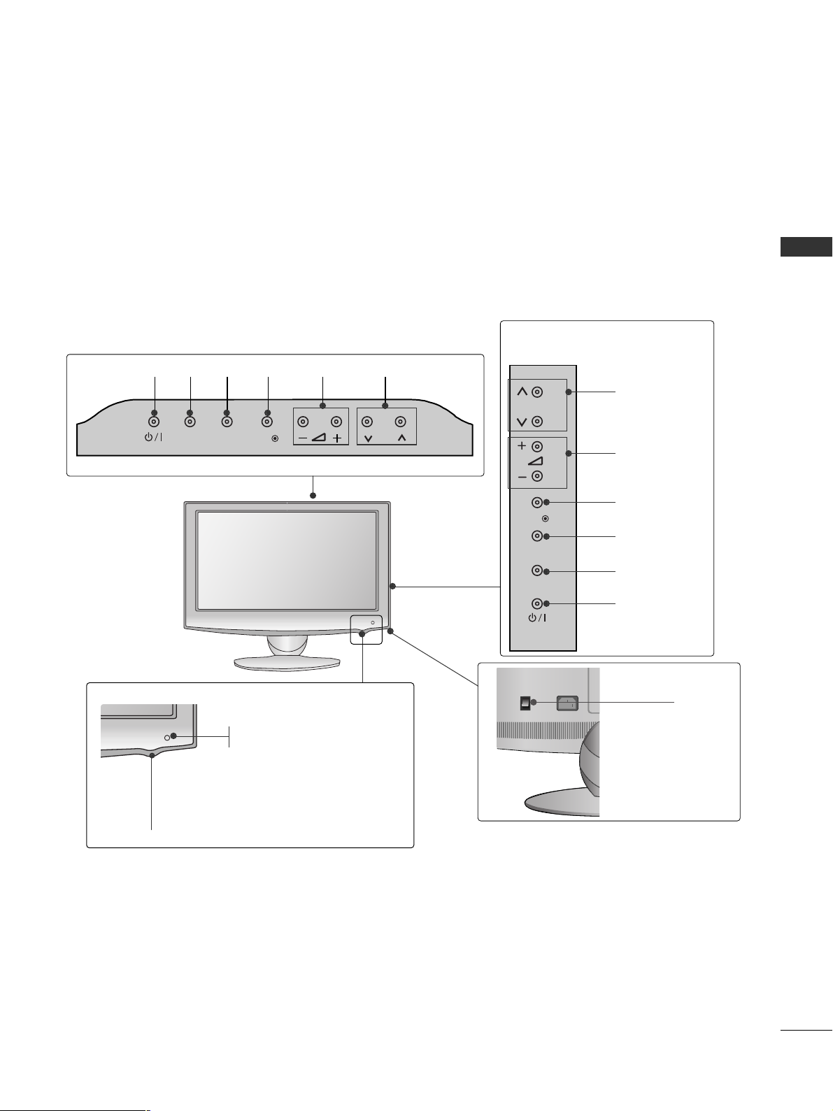
FRONT PANEL CONTROLS
■
Here shown may be somewhat different from your TV.
Only 32/37/42LH2***,
32/37/42/47LH3***
PROGRAMME
VOLUME
OK
Only 19/22/26LH2***
MENU
POWER
INPUT
INPUT
MENU
OK
P
PROGRAMME
VOLUME
OK
MENU
INPUT
POWER
Remote Control Sensor
Power/Standby Indicator
• Illuminates red in standby mode.
• Illuminates blue when the TV is switched on.
ON OFF
Only 19/22/26/32/37/42LH2***, 32/37/42/47LH3***
Main Power Switch
GG
When the TV cannot be turned on with the remote control, press the main power button on the TV.
(When the power is turned off with the main power button on the TV, it will not be turned on with the
remote control.)
CAUTION
Except 19/22LH2***
INPUT MENUPOK
Page 7
5
PREPARATION
■
Here shown may be somewhat different from your TV.
Only 19/22/26LU5
***
P
PROGRAMME
VOLUME
OK
MENU
INPUT
POWER
Only 19/22LU5***
Only 26LU5***
VOLUME
POWER
INPUT MENU OK
PROGRAMME
Main
Power
Switch
ON
OFF
P
Remote Control Sensor
Power/Standby Indicator
Illuminates red in standby mode.
Illuminates white when the TV is switched on.
INPUT
MENU
OK
P
P
OK
MENU
INPUT
Page 8

6
PREPARATION
PREPARATION
PROGRAMME
VOLUME
OK
MENU
INPUT
POWER Button
Power/Standby Indicator
• illuminates red in standby mode.
• illuminates blue when the TV is switched on.
Remote Control Sensor
Only 32/42LF2
***
■
Here shown may be somewhat different from your TV.
■
Here shown may be somewhat different from your TV.
Main Power Switch
OFF ON
PROGRAMME
VOLUME
MENU
OK
INPUT
POWER
Intelligent Sensor
Adjusts picture according to
the surrounding conditions.
Remote Control Sensor
Power/Standby Indicator
•
Illuminates red in standby mode.
• Illuminates white when the TV is switched on.
Only 42/47SL9
***
P
+
-
OK
MENU
INPUT
P
OK
MENU
INPUT
Page 9

7
PREPARATION
Only 37/42/47/55LH5
***
■
Here shown may be somewhat different from your TV.
PROGRAMME
VOLUME
OK
MENU
INPUT
POWER
Remote Control Sensor
Intelligent Sensor
Adjusts picture according to
the surrounding conditions.
Power/Standby Indicator
• Illuminates red in standby mode.
• Illuminates blue when the TV is switched on.
Main Power Switch
P
OK
MENU
INPUT
OFF ON
Page 10

8
PREPARATION
PREPARATION
Only 32/37/42/47LH7
***
■
Here shown may be somewhat different from your TV.
P
P
OK
MENU
INPUT
P
PROGRAMME
VOLUME
OK
MENU
INPUT
Intelligent Sensor
Adjusts picture according to
the surrounding conditions
POWER(Touch Sensor)
Power/Standby Indicator
• Illuminates red in standby mode.
• Illuminates Whitish when the TV is switched on.
Note: You can adjust
PP ooww ee rr IInndd iicc aa tt oorr
in the
OPTION menu.
Moving LED
Main Power Switch
Remote Control Sensor
Page 11

9
PREPARATION
Only 42/47LH9
***
PROGRAMME
VOLUME
OK
MENU
INPUT
POWER
Remote Control Sensor
Intelligent Sensor
Adjusts picture according to
the surrounding conditions.
Power/Standby Indicator
• Illuminates red in standby mode.
•
Illuminates white when the TV is switched on.
SPEAKER
Main Power Switch
■
Here shown may be somewhat different from your TV.
P
OK
MENU
INPUT
Page 12

10
PREPARATION
PREPARATION
■
Here shown may be somewhat different from your TV.
Only
32/42LH6***
PROGRAMMEVOLUMEMENU OKINPUTPOWER
Remote Control Sensor
Intelligent Sensor
Adjusts picture according to the surrounding conditions.
Power/Standby Indicator
•
Illuminates red in standby mode.
• Illuminates blue when the TV is switched on.
Main Power Switch
Power Indicator(Only 42LH6***)
• Illuminates blue when the TV is switched on.
Page 13

11
PREPARATION
Only 32/42/47/55SL8***
■
Here shown may be somewhat different from your TV.
Main Power Switch
OFF ON
PROGRAMME VOLUME
MENU
OK
INPUT
POWER
(Only 42/47/55SL8
***
)
Main Power Switch
OFFON
(Only 32SL8
***
)
Intelligent Sensor
Adjusts picture according
to the surrounding
conditions.
Remote Control
Sensor
Power/Standby Indicator
•
Illuminates red in standby mode.
•
Illuminates blue when the TV is switched on.
P
OK
MENU
INPUT
Page 14

12
PREPARATION
PREPARATION
■
Here shown may be somewhat different from your TV.
Only 19/22/26/32/37/42LH2***, 32/42LF2
***,
32/37/42/47LH3***
(Refer to p.13)
COMPONENT IN
AUDIO
VIDEO
L(L(MONO)MONO)
R
AUDIOAUDIO
AV IN
VIDEOVIDEO
IN
OUT
VARIABLE AUDIO OUTVARIABLE AUDIO OUT
ANTENNA IN
HDMI/DVI IN
RGB IN
(PC)
RS-232C IN
(CONTROL)
AUDIO IN
(RGB/DVI)
USB IN
SERVICE ONLY
3
2
7
9
L(MONO)
R
AUDIO
VIDEO
VARIABLE AUDIO OUT
ANTENNA IN
AUDIO
VIDEO
L(L(MONO)MONO)
R
AUDIOAUDIO
AV
VIDEOVIDEO
IN
OUT
VARIABLE AUDIO OUTVARIABLE AUDIO OUT
ANTENNA
IN
HDMI
/DVI IN
RGB IN
(PC)
RS-232C IN
(CONTROL)
AUDIO IN
(RGB/DVI)
USB IN
SERVICE ONLY
HDMI
1
2
COMPONENT IN
4
5
6
10
8
Only 26/32/37/42LH20**
Only 19/22LH2***
Only 32/37/42/47LH3***, 32/37/42LH23**
6
3
2
4
5
7
9
10
8
L(MONO)
R
AUDIO
VIDEO
VARIABLE AUDIO OUT
ANTENNA IN
L(MONO)
R
AUDIO
VIDEO
VARIABLE AUDIO OUT
ANTENNA
IN
COMPONENT IN
AUDIO
VIDEO
ANTENNA
IN
HDMI
/DVI IN
RGB IN
(PC)
RS-232C IN
(CONTROL)
AUDIO IN
(RGB/DVI)
HDMI
1
2
AV OUT
L/L/MONOMONO
R
AUDIOAUDIO
VIDEOVIDEO
VARIABLE AUDIO OUTVARIABLE AUDIO OUT
AV IN1
Only 32/37/42/47LH3***, 32/37/42LH23**
6
3
2
4
7
9
10
8
AV IN2
IN 3
2
8
11
1
MONO)
AUDIO
VIDEO
VARIABLE AUDIO OUT
3
2
7
9
4
5
6
10
8
Only 32/42LF2***
Only 32/42LF2***
AV IN2
IN 2
2
8
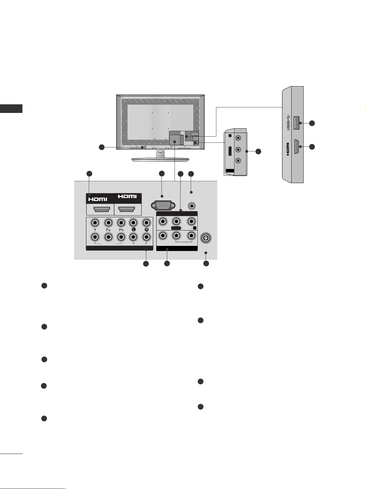
BACK PANEL INFORMATION
HDMI/DVI IN
1
VIDEO
COMPONENT IN
RS-232C IN
(CONTROL)
RGB IN
AUDIO
(PC)
USB IN
SERVICE ONLY
VIDEO
AUDIO IN
(RGB/DVI)
AUDIO
L(L(MONO)
VARIABLE AUDIO OUT
R
IN1
OUT
ANTENNA
IN
AV
Page 15

13
PREPARATION
AV IN2
IN 3
2
8
Only 26LU5***
ON
OFF
1
Power Cord Socket
This TV operates on an AC power. The voltage is
indicated on the Specifications page. Never
attempt to operate the TV on DC power.
HDMI Input
Connect a HDMI signal to HDMI IN.
Or DVI(VIDEO)signal to HDMI/DVI port with DVI
to HDMI cable.
RS-232C IN PORT
Connect to the RS-232C port on a PC.
This port is used for Service or Hotel mode.
RGB IN Input
Connect the output from a PC.
SERVICE ONLY PORT
RGB/DVI Audio Input
Connect the audio from a PC.
Component Input
Connect a component video/audio device to
these jacks.
Audio/Video Input
Connect audio/video output from an external
device to these jacks.
AV Output
Connect second TV or monitor to the AV OUT
socket on the TV.
Variable Audio Output
Connect an external amplifier or add a subwoofer
to your surround sound system.
Antenna Input
Connect RF antenna to this jack.
USB IN Input
Connect USB storage device to this jack.
1
2
3
4
5
6
8
9
10
11
7
11
2
8
1
Only 19/22/26LU5***, 37/42/47/55LH5
***
, 42/47LH9***
■
Here shown may be somewhat different from your TV.
AV OUT
L/L/MONOMONO
R
AUDIOAUDIO
VIDEOVIDEO
VARIABLE AUDIO OUTVARIABLE AUDIO OUT
ANTENNA
IN
RGB IN
(PC)
RS-232C IN
(CONTROL)
AUDIO IN
(RGB/DVI)
1
2
COMPONENT IN
AUDIO
VIDEO
1(DVI)
2
AV IN1
/DVI IN
3
2
7
9
4
6
10
8
Only 19/22/26LU5***
COMPONENT IN
AUDIO
VIDEO
HDMI/DVI IN
RGB IN
(PC)
RS-232C IN
(CONTROL)
AUDIO IN
(RGB/DVI)
USB IN
SERVICE ONLY
L(L(MONO)MONO)
R
AUDIOAUDIO
VIDEOVIDEO
1(DVI)
2
ANTENNA
IN
AV OUT
VARIABLE AUDIO OUTVARIABLE AUDIO OUT
AV IN
3
2
7
9
4
5
6
10
8
ANTENNA
IN
AV IN1
Only 26LU5***
IN 3
AV IN2
Page 16

14
PREPARATION
PREPARATION
1
Only 32/42LH6***
Power Cord Socket
This TV operates on an AC power. The voltage is
indicated on the Specifications page. Never
attempt to operate the TV on DC power.
HDMI Input
Connect a HDMI signal to HDMI IN.
Or DVI(VIDEO)signal to HDMI/DVI port with DVI
to HDMI cable.
RGB IN Input
Connect the output from a PC.
RGB/DVI Audio Input
Connect the audio from a PC.
Component Input
Connect a component video/audio device to
these jacks.
Audio/Video Input
Connect audio/video output from an external
device to these jacks.
AV Output
Connect second TV or monitor to the AV OUT
socket on the TV.
Variable Audio Output
Connect an external amplifier or add a subwoofer
to your surround sound system.
Antenna Input
Connect RF antenna to this jack.
USB IN Input
Connect USB storage device to this jack.
1
2
3
4
5
7
6
8
9
6
MONO
AUDIO
VIDEO
VARIABLE AUDIO OUT
■
Here shown may be somewhat different from your TV.
2
5
7
3
4
8
6
9
2
1(DVI)
2
2
1
/DVI IN
VIDEO
COMPONENT IN
RGB IN
AUDIO
(PC)
AUDIO IN
(RGB/DVI)
VIDEO
R
AUDIO
L/L/MONO
VARIABLE AUDIO OUT
AV OUT
IN 3
AV IN1
ANTENNA
IN
AV IN2
Page 17

15
PREPARATION
1
2
AUDIO IN
(RGB/DVI)
RGB IN
(PC)
RGB IN
COMPONENT IN
AUDIO
VIDEO
L/L/MONOMONO
R
AUDIOAUDIO
VIDEOVIDEO
VARIABLE AUDIO OUTVARIABLE AUDIO OUT
AV IN1
AV OUT
AV IN2
ANTENNA IN
RS-232C IN
(CONTROL)
2
5
7
1
Only 32/37/42/47LH7
***
Power Cord Socket
This TV operates on an AC power. The voltage is
indicated on the Specifications page. Never
attempt to operate the TV on DC power.
RGB IN Input
Connect the output from a PC.
RGB/DVI Audio Input
Connect the audio from a PC.
Audio/Video Input
Connect audio/video output from an external
device to these jacks.
RS-232C IN PORT
Connect to the RS-232C port on a PC.
This port is used for Service or Hotel mode.
Component Input
Connect a component video/audio device to
these jacks.
AV Output
Connect second TV or monitor to the AV OUT
socket on the TV.
Variable Audio Output
Connect an external amplifier or add a subwoofer
to your surround sound system.
Antenna Input
Connect RF antenna to this jack.
USB IN Input
Connect USB storage device to this jack.
HDMI Input
Connect a HDMI signal to HDMI IN.
Or DVI(VIDEO)signal to HDMI/DVI port with DVI
to HDMI cable.
1
2
3
4
6
7
8
4
3
6
8
9
5
9
■
Here shown may be somewhat different from your TV.
/DVI IN
3
2
1(DVI)
Page 18
16
PREPARATION
PREPARATION
Only
32/42/47/55SL8***
Power Cord Socket
This TV operates on an AC power. The voltage is
indicated on the Specifications page. Never
attempt to operate the TV on DC power.
HDMI IN Input
Connect a HDMI signal to HDMI IN. Or DVI (VIDEO)
signal to HDMI/DVI port with DVI to HDMI cable.
RGB IN Input
Connect the output from a PC.
Audio/Video Input
Connect audio/video output from an external
device to these jacks.
RGB/DVI Audio Input
Connect the audio from a PC.
Component Input
Connect a component video/audio device to
these jacks.
AV Output
Connect second TV or monitor to the AV OUT
socket on the TV.
Variable Audio Output
Connect an external amplifier or add a subwoofer
to your surround sound system.
Antenna Input
Connect RF antenna to this jack.
USB IN Input
Connect USB storage device to this jack.
1
2
3
4
5
6
7
8
9
■
Here shown may be somewhat different from your TV.
AV IN 2
L/MONO
R
AUDIOAUDIO
VIDEOVIDEO
4
AV IN 2
L/MONO
R
AUDIO
VIDEO
1
AV IN 2
L/MONO
R
AUDIO
VIDEO
IN 3
9
2
AV IN 2
L/MONO
R
AUDIO
VIDEO
MONO
AUDIO
VIDEO
VARIABLE AUDIO OUT
3
2
5
6
8
4
7
IN
/DVI IN
2
2
1
VIDEO
COMPONENT IN
1
AUDIO
RGB IN
VIDEO
(PC)
AUDIO IN
(RGB/DVI)
AV IN 1
AUDIO
L/L/MONO
VARIABLE AUDIO OUT
AV OUT
R
ANTENNA
IN
Page 19

17
PREPARATION
■
Here shown may be somewhat different from your TV.
1
IN 3
10
2
Only
42/47SL9***
2
IN
/DVI IN
1
1
2
COMPONENT IN
AUDIO
VIDEO
AV OUT
L/L/MONOMONO
R
AUDIOAUDIO
VIDEOVIDEO
VARIABLE AUDIO OUTVARIABLE AUDIO OUT
AV IN
RGB IN
(PC)
AUDIO IN
(RGB/DVI)
ANTENNA
IN
(CONTROL)
RS-232C IN
4
2
6
7
9
5
8
3
Power Cord Socket
This TV operates on an AC power. The voltage is
indicated on the Specifications page. Never
attempt to operate the TV on DC power.
HDMI IN Input
Connect a HDMI signal to HDMI IN. Or DVI (VIDEO)
signal to HDMI/DVI port with DVI to HDMI cable.
RGB IN Input
Connect the output from a PC.
RS-232C IN PORT
Connect to the RS-232C port on a PC.
This port is used for Service or Hotel mode.
Audio/Video Input
Connect audio/video output from an external
device to these jacks.
RGB/DVI Audio Input
Connect the audio from a PC.
Component Input
Connect a component video/audio device to
these jacks.
AV Output
Connect second TV or monitor to the AV OUT
socket on the TV.
Variable Audio Output
Connect an external amplifier or add a subwoofer
to your surround sound system.
Antenna Input
Connect RF antenna to this jack.
USB IN Input
Connect USB storage device to this jack.
1
2
3
4
5
7
8
9
10
6
CAUTION
G
Use a product with the following thickness
for optimal connection to HDMI cable(only
HDMI IN 3) / USB device.
*A 10mm
Page 20

18
PREPARATION
PREPARATION
STAND INSTALLATION
■
Here shown may be somewhat different from your TV.
When assembling the desk type stand, check whether the bolt is fully tightened. (If not tightened fully, the product can
tilt forward after the product installation.) If you tighten the bolt with excessive force, the bolt can deviate from abrasion
of the tightening part of the bolt.
Only 19/22/26LU5
***
1
2
Carefully place the TV screen side down on a cushioned surface to protect the screen from damage.
Fix the 2 or 3 bolts securely using the holes as
shown.
1
Carefully place the TV screen side down on a cushioned surface to protect the screen from damage.
2
Assemble the TV as shown.
Only 19/22LH2
***
Cover Base
(Only 26LU5
***
)
1
3
4
Carefully place the TV screen side down on a
cushioned surface to protect the screen from
damage.
2
Assemble the parts of the
SStt aa nndd BBoo dd yy
with
the
SStt aa nndd BBaass ee
of the TV.
Assemble the TV as shown.
Fix the 4 bolts securely using the holes in the
back of the TV.
Stand Body
Stand Base
Only 32/42LF2***
Page 21

19
PREPARATION
1
2
3
Carefully place the TV screen side down on a cushioned
surface to protect the screen from damage.
Assemble the TV as shown.
Fix the 4 bolts securely using the holes in the
back of the TV.
Only 26/32/37/42LH2***,
32/37/42/47LH3***,
37/42/47LH5
***
, 32/42LH6
***,
42/47LH9***
Only 32/37/42/47LH7
***
1
3
4
Carefully place the TV screen side down on a cushioned surface to protect the screen from damage.
2
Assemble the parts of the
SStt aa nndd BBoo dd yy
with
the
SStt aa nndd BBaass ee
of the TV.
Assemble the TV as shown.
Fix the 4 bolts securely using the holes in the
back of the TV.
32LH7
***
Stand Body
Stand Base
42LH7
***
47LH7
***
Stand Body
Stand Base
32/37LH7
***
42/47LH7
***
M4x20
M4x20
M4x16
M4x20
M4x16
M4x20
37LH7
***
■
Image shown may differ from your TV.
Page 22

20
PREPARATION
PREPARATION
1
3
4
Carefully place the TV screen side down on a cushioned surface to protect the screen from damage.
2
Assemble the parts of the
SStt aa nndd BBoo dd yy
with
the
SStt aa nndd BBaass ee
of the TV.
Assemble the TV as shown.
Fix the 4 bolts securely using the holes in the
back of the TV.
Stand Body
Stand Base
■
Image shown may differ from your TV.
Only 32/42/47SL8***
1
3
4
Carefully place the TV screen side down on a cushioned surface to protect the screen from damage.
2
Assemble the parts of the
SStt aa nndd BBoo dd yy
with
the
SStt aa nndd BBaass ee
of the TV.
Assemble the TV as shown.
Fix the 4 bolts securely using the holes in the
back of the TV.
Stand Body
Stand Base
20mm
16mm
Only 42/47SL9***
Page 23

21
PREPARATION
■
Here shown may be somewhat different from your TV.
When installing the wall-mounted unit, use the protection cover.
NOT USING THE DESK-TYPE STAND
Loose the bolts from TV.
Insert the
PPrrootteeccttiioonn CCoovveerr
into the TV.
Detach the
SStt aa nndd BBoo dd yy
from
TT VV
.
Fix the 4 bolts securely using the holes in the
back of the TV.
2
3
4
Only 19/22LH2
***
1
Carefully place the TV screen side down on a cush-
ioned surface to protect the screen from damage.
5
Protection Cover
Page 24

22
PREPARATION
PREPARATION
After removing the protection paper from the protection cover, adhere it to the TV as shown.
Only
42/47LH9***
Insert the
PPRROOTTEECCTTIIOONN
CC OOVV EERR
into the TV until
clicking sound.
PROTECTION COVER
Only 32/42/47/55SL8***
Only 26/32/37/42LH2***,
32/37/42/47LH3***, 37/42/47/55LH5***,
32/42LH6***
Only 32/37/42/47LH7
***
Insert the
PPRROOTTEECCTTIIOONN CCOOVVEE RR
into the TV until clicking sound.
After removing the protection paper
from the protection cover, adhere it
to the TV as shown.
PROTECTION COVER
Insert the
PPRROOTTEECCTTIIOONN
CC OOVV EERR
into the TV
until clicking sound.
Only 32/42LF2***
Page 25

23
PREPARATION
TO USE THE STAND REAR COVER (37/42/47LH7
***
only)
Install the
SSTTAANNDD RREEAARR CCOOVVEERR
as shown.
STAND REAR COVER
SWIVEL STAND
(Except 19/22/26LU5
***,
19/22LH2***
)
■
This feature is not available for all models.
■
After installing the TV, you can adjust the TV manually
to the left or right direction by 20 degrees to suit your
viewing position.
POSITIONING YOUR DISPLAY
(Only 19/22LH2***)
■
Here shown may be somewhat different from your TV.
■
Adjust the position of the panel in various ways for
maximum comfort.
• Tilt range
12
0
3
0
ATTACHING THE TV TO A DESK
■
Here shown may be somewhat different from your TV.
The TV must be attached to desk so it cannot be pulled
in a forward/backward direction, potentially causing
injury or damaging the product. Use only an attached
screw.
1-Screw (provided as parts of the product)
Desk
Stand
WARNING
!
G
To prevent TV from falling over, the TV should
be securely attached to the floor/wall per installation instructions. Tipping, shaking, or rocking the
machine may cause injury.
Only 26/32/37/42LH2
***,
32/42LF2***, 32/37/42LH3***,
26LU5***, 37/42LH5***,
32/42LH6***, 32/37LH7***,
42LH9***
■
Here shown may be somewhat different from your TV.
Grip the knob in your fingers and pull it.
NOTE
!
G
The following model is a fixed stand type
model without the Tilt and Swivel features so
excessive pressure may damage the set.
- 19/22/26LU5***
Page 26

24
PREPARATION
PREPARATION
BACK COVER FOR WIRE ARRANGEMENT
■
Here shown may be somewhat different from your TV.
Connect the cables as necessary.
To connect additional equipment, see the
EXTERNAL EQUIPMENT SETUP section.
Fit the CABLE MANAGEMENT CLIP as shown.
Only 19/22LH2
***
How to remove the CABLE MANAGEMENT CLIP(
Only 19/22LH2
***
)
GG
Hold the CABLE MANAGEMENT CLIP with both hands
and pull it backward.
CABLE MANAGEMENT CLIP
Connect the cables as necessary.
To connect additional equipment, see the
External Equipment Setup section of the manual.
1
Open the
CC AABB LL EE MMAANN AAGGEE MMEE NNTT CCLLIIPP
as
shown and manage the cables.
2
CABLE MANAGEMENT CLIP
Fit the
CC AABB LL EE MMAANN AAGGEE MMEE NNTT CCLLIIPP
as
shown.
3
Only 19/22/26/32/37/42LH2***,
32/42LF2***, 32/37/42/47LH3***,
37/42/47/55LH5
***, 32/42LH6***,
42/47LH9***
1
Install the CABLE MANAGEMENT CLIP as shown.
2
3
Only 19/22/26LU5
***
After Connecting the cables as necessary, install
CABLE HOLDER as shown and bundle the cables.
Page 27

25
PREPARATION
Only 32/37/42/47LH7
***
1
2
Connect the cables as necessary.
To connect additional equipment, see the
EExxttee rrnn aall eeqquu iipp mm eenntt SSee tt uupp
section.
Align the hole with the tab on the
CC AABBLLEE
MMAA NNAAGGEE MMEE NNTT CCLL II PP
.
Turn the
CC AABB LL EE MMAANN AAGGEE MMEE NNTT CCLLIIPP
as
shown.
Note : that excessive force might cause dam-
age to the product when using Cable
Management clip.
CABLE MANAGEMENT CLIP
Only 32/42/47/55SL8***,
42/47SL9***
Install the CABLE MANAGEMENT CLIP as
shown.
1
CABLE MANAGEMENT CLIP
Connect the cables as necessary. To connect
additional equipment, see the EXTERNAL
EQUIPMENT SETUP section.
2
NOTE
!
GG
Do not use the CABLE MANAGEMENT CLIP to
lift the TV.
- If the TV is dropped, you may be injured or the
TV may be damaged.
After Connecting the cables as necessary,
install CABLE HOLDER as shown and bundle
the cables. To connect additional equipment,
see the
EExxttee rrnn aall eeqquu iipp mm eenntt SSee tt uupp
section.
1
CABLE HOLDER
FOR DESK-TYPE STAND
FOR WALL MOUNT
Page 28

26
PREPARATION
PREPARATION
2
Loose the bolts and then detach the stand from
TV.
3
Loose the bolts and then detach the
CC oo vvee rr
BBaass ee
from
TT VV
.
4
Detach the
SStt aa nndd BBoo dd yy
from
TT VV
.
Stand Body
DETACHING STAND
1
Carefully place the TV screen side down on a cushioned surface to protect the screen from damage.
Cover Base
Only 19/22/26LU5
***
(Only 26LU5
***
)
■
Here shown may be somewhat different from your TV.
(Only 26LU5
***
)
KENSINGTON SECURITY SYSTEM
■
This feature is not available for all models.
■
Here shown may be somewhat different from your TV.
The TV is equipped with a Kensington Security
System connector on the back panel. Connect the
Kensington Security System cable as shown below.
For the detailed installation and use of the
Kensington Security System, refer to the user’s guide
provided with the Kensington Security System.
For further information, contact http://www.kensing-
ton.com, the internet homepage of the Kensington
company. Kensington sells security systems for
expensive electronic equipment such as notebook
PCs and LCD projectors.
NOTE
- The Kensington Security System is an optional accessory.
NOTES
a. If the TV feels cold to the touch, there may be a
small “flicker” when when it is turned on.
This is normal, there is nothing wrong with TV.
b. Some minute dot defects may be visible on the
screen, appearing as tiny red, green, or blue spots.
However, they have no adverse effect on the monitor's performance.
c. Avoid touching the LCD screen or holding your finger(s)
against it for long periods of time.
Doing so may produce some temporary distortion
effects on the screen.
Page 29

27
PREPARATION
A
The TV can be installed in various ways such as on
a wall, or on a desktop etc.
A
The TV is designed to be mounted horizontally.
Power Supply
Circuit breaker
EARTHING
Ensure that you connect the earth wire to prevent
possible electric shock. If grounding methods are not
possible, have a qualified electrician install a separate
circuit breaker.
Do not try to earth the TV by connecting it to telephone wires, lightening rods or gas pipes.
4 inches
4 inches
4 inches
4 inches
DESKTOP PEDESTAL INSTALLATION
For adequate ventilation allow a clearance of 4”
(10cm) all around the TV.
CAREFUL INSTALLATION ADVICE
A
You should purchase necessary components to fix the TV
safety and secure to the wall on the market.
A
Position the TV close to the wall to avoid the possibility
of it falling when pushed.
A
The instructions shown below are a safer way to set up
the TV, by fixing it to the wall, avoiding the possibility of
it falling forwards if pulled. This will prevent the TV from
falling forward and causing injury. This will also prevent
the TV from damage. Ensure that children do not climb
or hang from the TV.
NOTE
!
G
When moving the TV undo the cords first.
G
Use a platform or cabinet strong and large enough
to support the size and weight of the TV.
G
To use the TV safely make sure that the height of the
bracket on the wall and on the TV is the same.
3
1
2
Use the eye-bolts or TV brackets/bolts to fix the
product to the wall as shown in the picture.
(If your TV has bolts in the eyebolts, loosen then
bolts.)
* Insert the eye-bolts or TV brackets/bolts and tight-
en them securely in the upper holes.
Secure the wall brackets with the bolts on the wall.
Match the height of the bracket that is mounted on
the wall.
3
Use a sturdy rope to tie the product for alignment. It
is safer to tie the rope so it becomes horizontal
between the wall and the product.
2
1
2
1
How to secure the power cable
(Only 32/37/42/47LH7
***
)
PROTECTIVE BRACKET
Bolt
Secure the power cable with the PROTECTIVE BRACKET
and the bolt as shown. It will help prevent the power cable
from being removed by accident.
Page 30

28
PREPARATION
PREPARATION
WALL MOUNT: HORIZONTAL INSTALLATION
A
We recommend the use of a LG Brand wall mounting
bracket when mounting the TV to a wall.
A
We recommend that you purchase a wall mounting
bracket which supports VESA standard.
A
LG recommends that wall mounting be performed
by a qualified professional installer.
A
First you connect the USB extension cable to the
USB IN terminal, and then hang it on the wall.(Only
32/37/42/47LH7***)
4 inches
4 inches
4 inches
4 inches
4 inches
NOTE
!
G Should Install wall mount on a solid wall perpendicular to
the floor.
G Should use a special wall mount, if you want to install it to
ceiling or slanted wall.
G The surface that wall mount is to be mounted on should
be of sufficient strength to support the weight of TV set;
e.g. concrete, natural rock, brick and hollow block.
G Installing screw type and length depends on the wall
mount used. Further information, refer to the instructions
included with the mount.
G LG is not liable for any accidents or damage to property or
TV due to incorrect installation:
- Where a non-compliant VESA wall mount is used.
- Incorrect fastening of screws to surface which may cause
TV to fall and cause personal injury.
- Not following the recommended Installation method.
Model
VESA
(A *B)
Standard
Screw
Quantity
AA
BB
47SL9***
42SL9***
55SL8***
47SL8***
42SL8***
32SL8***
47LH9***
42LH9***
47LH7***
42LH7***
37LH7***
32LH7***
42LH6***
32LH6***
55LH5***
47LH5***
42LH5***
37LH5***
26LU5***
22LU5***
19LU5***
47LH3***
42LH3***
37LH3***
32LH3***
42LH2***
37LH2***
32LH2***
26LH2***
22LH2***
19LH2***
42LF2***
32LF2***
200 * 200
200 * 200
400 * 400
200 * 200
200 * 200
200 * 10 0
200 * 200
200 * 200
200 * 200
200 * 200
200 * 200
200 * 10 0
200 * 200
200 * 10 0
400 * 400
200 * 200
200 * 200
200 * 200
200 * 10 0
100 * 10 0
100 * 10 0
200 * 200
200 * 200
200 * 200
200 * 10 0
200 * 200
200 * 200
200 * 10 0
200 * 10 0
100 * 10 0
100 * 10 0
200 * 200
200 * 10 0
M6
M6
M6
M6
M6
M4
M6
M6
M6
M6
M6
M4
M6
M4
M6
M6
M6
M6
M4
M4
M4
M6
M6
M6
M4
M6
M6
M4
M4
M4
M4
M6
M4
4
4
4
4
4
4
4
4
4
4
4
4
4
4
4
4
4
4
4
4
4
4
4
4
4
4
4
4
4
4
4
4
4
Page 31

29
PREPARATION
ANTENNA
IN
ANTENNA
IN
ANTENNA CONNECTION
■
For optimum picture quality, adjust antenna direction.
■
An antenna cable and converter are not supplied.
■
To prevent damage do not connect to the mains outlet until all connections are made between the devices.
Multi-family Dwellings/Apartments
(Connect to wall antenna socket)
Single-family Dwellings /Houses
(Connect to wall jack for outdoor antenna)
Outdoor
Antenna
(VHF, UHF)
Wall
Antenna
Socket
RF Coaxial Wire (75 ohm)
Antenna
UHF
Signal
Amplifier
VHF
■
In poor signal areas, to achieve better picture quality it may be necessary to install a signal amplifier to the
antenna as shown above.
■
If signal needs to be split for two TVs, use an antenna signal splitter for connection.
Page 32

30
EXTERNAL EQUIPMENT SETUP
EXTERNAL EQUIPMENT SETUP
1
2
COMPONENT IN
AUDIO
VIDEO
HD RECEIVER SETUP
■
To avoid damaging any equipment, never plug in any power cords until you have finished connecting all equipment.
■
This section on EXTERNAL EQUIPMENT SETUP mainly uses diagrams for the 37/42/47/55LH5*** models.
■
Here shown may be somewhat different from your TV.
Connecting with a component cable
1
2
Signal
480i/576i
480p/576p
720p/1080i
10 8 0 p
Component
O
O
O
O
(50/60Hz only)
HDMI
X
O
O
O
(24Hz/30Hz/50Hz/60Hz)
Connect the video outputs (Y, PB, PR
)
of the digital set
top box to the
CC OOMMPPOONN EENNTT IINN VVIIDD EEOO
jacks on the
TV.
Connect the audio output of the digital set-top box to
the
CC OOMMPPOONN EENNTT IINN AA UUDDIIOO
jacks on the TV.
Turn on the digital set-top box.
(
Refer to the owner’s manual for the digital set-top box.
)
Select
CC oo mm pp oonn eenntt11
input source using the
IINN PPUU TT
button on the remote control.
If connected to
CC OOMMPPOONN EENNTT IINN 22
, select
CC oo mm pp oonneenntt22
input source.
2
3
4
1
Page 33

31
EXTERNAL EQUIPMENT SETUP
Connecting a set-top box with an HDMI cable
Connect the digital set-top box to
HHDDMMII// DDVV II IINN 11
,
HHDDMMII IINN 22
(Except 19/22LH2***) or
HHDDMMII IINN
33
(Except 19/22/26/32/37/42LH20**, 32/42LF2***,
19/22LU5***) jack on the TV.
Turn on the digital set-top box.
(
Refer to the owner’s manual for the digital set-top box.
)
Select
HH DD MMII11, HH DD MMII22
(Except 19/22LH2***) or
HH DD MMII33
(Except 19/22/26/32/37/42LH20**,
32/42LF2***, 19/22LU5***)input source using the
IINN PPUU TT
button on the remote control.
2
3
1
GG
Check that your HDMI cable is version 1.3 or higher.
If the HDMI cables don’t support HDMI version 1.3,
flickering or no screen display can result. Please use the
latest cables that support at least HDMI version 1.3.
GG
We recommed less than 10m for HDMI cable, and recommend to use amplifier or repeater for more than that.
NOTE
!
1(DVI)
2
/DVI IN
1
Page 34

32
EXTERNAL EQUIPMENT SETUP
EXTERNAL EQUIPMENT SETUP
Connecting with an HDMI to DVI cable
Connect the digital set-top box to
HHDDMMII// DDVV II IINN 11
jack on the TV.
Connect the audio output of the digital set-top box to
the
AAUU DDIIOO IINN ((RRGGBB//DD VVII))
jack on the TV.
Turn on the digital set-top box. (Refer to the owner’s
manual for the digital set-top box.
)
Select
HH DD MMII11
input source using the
IINN PPUU TT
button
on the remote control.
2
3
4
1
COMPONENT IN
VIDEO
LYP
BPR
R
AUDIO
VIDEO
AU
/MONO
1
2
RGB IN
(PC)
RS-232C IN
(CONTROL)
AUDIO IN
(RGB/DVI)
1(DVI)
2
/DVI IN
AV OUT
VARIABLE AUDI
1
2
Page 35

33
EXTERNAL EQUIPMENT SETUP
DVD SETUP
Connecting with a component cable
1
2
COMPONENT IN
AUDIO
VIDEO
L(MONO)
R
AUDIO
VIDEO
VARIABLE AUDIO OUT
Component Input ports
To achieve better picture quality, connect a DVD player to the component input ports as shown below.
Component ports on the TV
YPB PR
Video output ports
on DVD player
Y
Y
Y
Y
PB
B-Y
Cb
Pb
P
R
R-Y
Cr
Pr
1
2
Connect the video outputs (Y, PB, PR
)
of the DVD to the
CC OOMMPPOONN EENNTT IINN VV II DDEEOO
jacks on the TV.
Connect the audio outputs of the DVD to the
CC OOMMPPOONN EENNTT IINN AA UUDDIIOO
jacks on the TV.
Turn on the DVD player, insert a DVD.
Select
CC oo mm pp oonneenntt11
input source using the
IINN PPUU TT
button on the remote control.
If connected to
CC OOMMPPOO NNEENN TT IINN 22
, select
CC oo mm pp oonn eenntt22
input source.
Refer to the DVD player's manual for operating instructions.
2
3
4
5
1
Page 36

34
EXTERNAL EQUIPMENT SETUP
EXTERNAL EQUIPMENT SETUP
Connecting the HDMI cable
Connect the HDMI output of the DVD to the
HHDDMMII// DDVV II IINN 11,HHDDMMII IINN 22
(Except 19/22LH2***)
or
HHDDMMII II NN 33
(Except 19/22/26/32/37/42LH20**,
32/42LF2***, 19/22LU5***) jack on the TV.
Select
HH DD MMII11, HH DD MMII22
(Except 19/22LH2***) or
HH DD MMII33
(Except 19/22/26/32/37/42LH20**,
32/42LF2***, 19/22LU5***) input source using the
IINN PPUU TT
button on the remote control.
Refer to the DVD player's manual for operating instructions.
2
3
1
GG
The TV can receive video and audio signals simultaneously when using a HDMI cable.
GG
If the DVD does not support Auto HDMI, you must set the output resolution appropriately.
GG
Check that your HDMI cable is version 1.3 or higher.
If the HDMI cables don’t support HDMI version 1.3, flickering or no screen display can result.
Please use the latest cables that support at least HDMI version 1.3.
GG
We recommed less than 10m for HDMI cable, and recommend to use amplifier or repeater for
more than that.
NOTE
!
1(DVI)
2
/DVI IN
L(MONO)
R
AUDIO
VIDEO
VARIABLE AUDIO OUT
1
Page 37

35
EXTERNAL EQUIPMENT SETUP
VCR SETUP
■
To avoid picture noise (interference), allow adequate distance between the VCR and TV.
AV IN 1
VIDEO
AUDIO
/MONO
ANTENNA
IN
AV OUT
VARIABLE AUDIO OUT
OUTPUT
SWITCH
ANT IN
R
S-VIDEO VIDEO
ANT OUT
L
Wall Jack
Antenna
1
2
Connecting with a RF Cable
Connect the
AANN TT OO UU TT
socket of the VCR to the
AANN TTEENNNN AA IINN
socket on the TV.
Connect the antenna cable to the
AANN TT IINN
socket of the VCR.
Press the
PPLLAA YY
button on the VCR and match the appropriate channel between the TV and VCR for
viewing.
2
3
1
Page 38

36
EXTERNAL EQUIPMENT SETUP
EXTERNAL EQUIPMENT SETUP
Connecting with a RCA cable
L(MONO)
R
AUDIO
VIDEO
VARIABLE AUDIO OUT
L R
AUDIO
AV OUT
VARIABLE AUDIO OUT
L/L/MONOMONO
R
AUDIOAUDIO
VIDEOVIDEO
AV IN1
L
R
S-VIDEO
VIDEO
OUTPUT
SWITCH
ANT IN
ANT OUT
Connect the
AAUUDDIIOO/VVIIDD EEOO
jacks between TV and
VCR. Match the jack colours (Video = yellow, Audio Left
= white, and Audio Right = red)
Insert a video tape into the VCR and press PLAY on
the VCR. (Refer to the VCR owner’s manual.
)
Select
AA VV 11
input source using the
IINN PPUU TT
button on
the remote control.
If connected to
AAVV IINN 22
, select
AA VV 22
input source.
1
2
3
GG
If you have a mono VCR, connect the audio cable from the
VCR to the
AAUU DDIIOO LL//MMOO NNOO
jack of the TV.
NOTE
!
1
AV IN2
L
R
S-VIDEO
VIDEO
OUTPUT
SWITCH
ANT IN
ANT OUT
1
or
EXTERNAL EQUIPMENT SETUP
Page 39

37
EXTERNAL EQUIPMENT SETUP
OTHER A/V SOURCE SETUP
Connect the
AAUUDDIIOO/VVIIDD EEOO
jacks between TV and external equipment. Match the jack colours
.
(
Video = yellow, Audio Left = white, and Audio Right = red
)
Select
AA VV 11
input source with using the
IINN PPUU TT
button on the remote control.
If connected to
AAVV IINN 22
, select
AA VV 22
input source.
Operate the corresponding external equipment.
Refer to external equipment operating guide.
AV IN2
IN 3
L R
VIDEO
Camcorder
Video Game Set
1
1
2
3
L R
AUDIO
RGB IN
(PC)
RS 232C IN
(CONTROL)
AUDIO IN
(RGB/DVI)
AV OUT
VARIABLE AUDIO OUT
L/L/MONOMONO
R
AUDIOAUDIO
VIDEOVIDEO
AV IN1
L R
VIDEO
ANTENNA
IN
Camcorder
Video Game Set
1
or
Page 40

38
EXTERNAL EQUIPMENT SETUP
EXTERNAL EQUIPMENT SETUP
EXTERNAL STEREO SETUP
VARIABLE AUDIO OUT
AV IN 1
L R
AUDIO
VIDEO
AUDIO
/MONO
ANTENNA
IN
AV OUT
VARIABLE AUDIO OUTVARIABLE AUDIO OUT
GG
When connecting with external audio equipments, such as
amplifiers or speakers, please turn the TV speakers off.
(
GG
pp..111155
)
GG
Select
VVaarriiaabbllee OOuutt
in
AAUUDDIIOO
menu to connect the
VVAA RRIIAABB LL EE AAUUDDIIOO OO UUTT
jacks.(
GG
pp..111166
)
NOTE
!
Use to connected either an external amplifier, or add a sub-woofer
to your surround sound system.
Connect the input jack of the stereo amplifier to the
VVAA RRIIAABB LL EE AAUUDDIIOO OO UUTT
jacks on the TV.
Set up your speakers through your analog stereo
amplifier, according to the instructions provided with
the amplifier.
2
1
11
EXTERNAL EQUIPMENT SETUP
Page 41

39
EXTERNAL EQUIPMENT SETUP
AV OUTPUT SETUP
The TV has a special signal output capability which allows you
to hook up the second TV or monitor.
AV IN 1
R
VIDEO
AUDIO
/MONO
ANTENNA
IN
AV OUT
VARIABLE AUDIO OUTVARIABLE AUDIO OUT
L R
S-VIDEO
VIDEO
Connect the second TV or monitor to the TV’s
AAVV OOUUTT
jacks.
See the Operating Manual of the second TV or monitor
for further details regarding that device’s input settings.
GG
Component, RGB, HDMI input sources cannot be used for
AV out.
GG
We recommend to use the AV OUT jacks for VCR recording.
NOTE
!
2
1
1
Page 42

40
EXTERNAL EQUIPMENT SETUP
EXTERNAL EQUIPMENT SETUP
USB IN SETUP
(except 19/22/26/32/37/42LH20**, 32/42LF2***, 19/22/26LU5***)
IN 3
Connect the USB device to the
UUSSBB IINN
jack on the TV.
After connecting the
UUSSBB IINN
jacks, you use the
UU SSBB
function. (
GG
pp..8822
)
2
1
1
■
Here shown may differ from your TV.
Page 43

41
EXTERNAL EQUIPMENT SETUP
PC SETUP
This TV provides Plug and Play capability, meaning that the PC
adjusts automatically to the TV's settings.
Connecting with a D-sub 15 pin cable
COMPONENT IN
VIDEO
LP
BPR
R
AUDIO
VIDEO
AUDIO
/MONO
RS-232C IN
(CONTROL)
/DVI IN
AV OUT
VARIABLE AUDIO OUT
RGB IN
(PC)
AUDIO IN
(RGB/DVI)
RGB OUTPUT
AUDIO
1 2
4
Connect the RGB output of the PC to the
RRGGBB II NN
(( PPCC))
jack on the TV.
Connect the PC audio output to the
AAUU DDIIOO II NN
((RRGGBB// DDVV II ))
jack on the TV.
Turn on the TV and the PC.
Select
RR GGBB
input source using the
IINN PPUU TT
button on
the remote control.
2
3
1
Page 44

42
EXTERNAL EQUIPMENT SETUP
EXTERNAL EQUIPMENT SETUP
Resolution
720x480
720x576
1280x720
1920x1080i
1920x1080p
HDMI-DTV mode
Horizontal Vertical
Frequency(kHz) Frequency(Hz)
31.47 59.94
31.50 60.00
31.25 50.00
44.96 59.94
45.00 60.00
37.50 50.00
33.75 60.00
33.72 59.94
28.125 50.00
67.432 59. 94
67.5 60
56.250 50
27 24
33.75 30
Resolution
640x350
720x400
640x480
800x600
1024x768
1280x768
1360x768
1280x1024
1920x1080
RGB-PC mode
Horizontal Vertical
Frequency(kHz) Frequency(Hz)
31.468 70.09
31.469 70.09
31.469 59.94
37.879 60.317
48.363 60.004
47.776 59 .87
47.720 59. 799
63.668 59.895
66.587 59.934
Except 19LU5***, 19/22/26/32/37/42LH2***
Supported Display Resolution
Page 45

43
EXTERNAL EQUIPMENT SETUP
NOTE
!
GG
Avoid keeping a fixed image on the TV ’s screen
for prolonged periods of time.The fixed image
may become permanently imprinted on the
screen;use a screen saver when possible.
GG
There may be interference relating to resolution,
vertical pattern, contrast or brightness in PC
mode. Change the PC mode to another resolu-
tion or change the refresh rate to another rate
or adjust the brightness and contrast on the
menu until the picture is clear. If the refresh rate
of the PC graphic card can not be changed,
change the PC graphic card or consult the man-
ufacturer of the PC graphic card.
GG
The synchronization input waveform for
Horizontal and Vertical frequencies are separate.
GG
If the resolution of PC is over SXGA, there will
be no picture on the TV.(only HD Models)
GG
Connect the audio cable from the PC to the
Audio input on the TV.(Audio cables are not
included with the TV).
GG
If you use too long an RGB-PC cable, there may
be interference on the screen. We recommend
using under 5m of the cable. This provides the
best picture quality.
GG
We recommend using
1920x1080, 60Hz (Only
19LU5***, 19/22/26/32/37/42LH2***:
13 6 0
x
768 , 60 H z)for the PC mode, these
should provide the best picture quality.
GG
HDMI mode supports PCM audio format only.
GG
If the Audio setting is set to
Dolby/DTS/Bitstream in some DVDP/STB, make
sure to change the setting to PCM.
Page 46

44
EXTERNAL EQUIPMENT SETUP
EXTERNAL EQUIPMENT SETUP
1
MENU
Screen Setup for PC mode
Returns Position, Size and Phase to the factory default settings.
This function works in the following mode : RGB[PC], Component(except 480i, 576i).
Screen Reset
Select
PPIICCTT UURREE
.
Select
SScc rree eenn
.
3
Select
RReess eett
.
To Set
Auto Config.
Screen
Move
Prev.
Resolution
Position
Size
Phase
Reset
G
2
OK
OK
• Press the
MMEE NNUU
button to return to normal TV viewing.
• Press the
RR EETT UU RRNN
button to move to the previous menu screen.
Select
YY eess
.
Run
RReess eett
.
4
OK
5
OK
OK
Move
• Contrast 90
• Brightness 50
• Sharpness 60
• Colour 60
• Tint 0
• Advanced Control
• Picture Reset
Screen
PICTURE
RG
E
Screen
Yes No
Page 47

45
EXTERNAL EQUIPMENT SETUP
If the picture is not clear after auto adjustment and especially if characters are still trembling, adjust the
picture phase manually.
PPoo ssiittiioo nn
operates in Component(except 480i, 576i), RGB mode.
SS iizz ee,PPhhaassee
operate only in RGB mode.
Adjustment for screen Position, Size, Phase
Select
PPIICCTT UURREE
.
Select
SScc rree eenn
.
Select
PPoo ssiittiioonn, SSiizz ee
or
PPhhaass ee
.
Make appropriate adjustments.
Auto Config.
Resolution
Position
G
Size
Phase
Reset
GF
D
E
Screen
Move
Prev.
1
MENU
3
4
2
OK
OK
• Press the
MMEE NNUU
button to return to normal TV viewing.
• Press the
RR EETT UU RRNN
button to move to the previous menu screen.
OK
Move
• Contrast 90
• Brightness 50
• Sharpness 60
• Colour 60
• Tint 0
• Advanced Control
• Picture Reset
Screen
PICTURE
RG
E
Screen
Page 48

46
EXTERNAL EQUIPMENT SETUP
EXTERNAL EQUIPMENT SETUP
EXTERNAL EQUIPMENT SETUP
To view a normal picture, match the resolution of RGB mode and selection of PC mode.
This function works in the following mode: RGB[PC]
Selecting Resolution
Select
PPIICCTT UURREE
.
Select
SScc rree eenn
.
Select
RReessoolluuttiioonn
.
Select the desired resolution.
Auto Config.
Resolution
G
Position
Size
Phase
Reset
Screen
Move
Prev.
1
MENU
3
4
2
OK
OK
• Press the
MMEE NNUU
button to return to normal TV viewing.
• Press the
RR EETT UU RRNN
button to move to the previous menu screen.
OK
Move
• Contrast 90
• Brightness 50
• Sharpness 60
• Colour 60
• Tint 0
• Advanced Control
• Picture Reset
Screen
PICTURE
RG
E
Screen
1024 x 768
1280 x 768
1360 x 768
Page 49

47
EXTERNAL EQUIPMENT SETUP
Automatically adjusts the picture position and minimizes image instability. After adjustment, if the image is
still not correct, your TV is functioning properly but needs further adjustment.
AAuutt oo ccoonnffiigguurree
This function is for automatic adjustment of the screen position, size, and phase.
The displayed image will be unstable for a few seconds while the auto configuration is in progress.
Auto Configure (RGB [PC] mode only)
• If the position of the image is still not correct,
try Auto adjustment again.
• If picture needs to be adjusted again after Auto
adjustment in RGB(PC), you can adjust the
PPoo ssiittiioonn, SSiizz ee
or
PPhhaass ee
.
Select
PPIICCTT UURREE
.
Select
SScc rree eenn
.
Select
AAuuttoo CCoonnffiigg ..
.
Auto Config.
G
Resolution
Position
Size
Phase
Reset
Screen
Move
Prev.
To Set
1
MENU
3
2
OK
OK
• Press the
MMEE NNUU
button to return to normal TV viewing.
• Press the
RR EETT UU RRNN
button to move to the previous menu screen.
Select
YY eess
.
Run
AAuuttoo CCoonnffiigg ..
.
4
OK
5
OK
OK
Move
• Contrast 90
• Brightness 50
• Sharpness 60
• Colour 60
• Tint 0
• Advanced Control
• Picture Reset
Screen
PICTURE
RG
E
Screen
Yes No
Page 50

48
WATCHING TV / PROGRAMME CONTROL
WATCHING TV / PROGRAMME CONTROL
REMOTE CONTROL KEY FUNCTIONS
(Only 42/47LH9***, 32/42/47/55SL8***)
When using the remote control, aim it at the remote control sensor on the TV.
POWERPOWER
TV
ON/OFFON/OFF
MARKMARK
FAV
AV MODEV MODE
POWER
ON/OFF
TV
ENERGY SAVING
AV MODE
INPUT
Switches the TV on from standby or off to standby.
Key lighting on or off.(Only 42/47LH9***)
Selects TV channel.
Adjust the Energy Saving mode of the TV.
It helps you select and set images and sounds when connecting AV devices.(
GG
pp..77 33
)
External input mode rotate in regular sequence.
0~9 number
button
LIST
Q.VIEW
Selects a programme.
Selects numbered items in a menu.
Displays the programme List.
Returns to the previously viewed programme.
MENU
Q. MENU
THUMBSTICK
(Up/Down/Left/Right)
OK
RETURN
Selects a menu.
Clears all on-screen displays and returns to TV viewing
from any menu.
Select the desired quick menu source.(Aspect Ratio,
Clear Voice II, Picture Mode, Sound Mode, AUDIO,
Sleep Timer, Favourite, USB Device) (
GG
pp..55 88
)
Allows you to navigate the on-screen menus and adjust
the system settings to your preference.
Accepts your selection or displays the current mode.
Enter to the mode.
Allows the user to move return one step in an interactive
application or other user interaction function.
Coloured
buttons
These buttons are used for teletext (on
TTEE LL EETTEE XXTT
models only),
PPrroo ggrraa mm mm ee eeddii tt
.
TELETEXT
BUTTONS
These buttons are used for teletext.
For further details, see the ‘Teletext’ section.(
GG
pp..11 2233
)
See a list of AV devices connected to TV.
When you toggle this button, the Simplink menu appears
at the screen.(
GG
pp..66 99
)
1
1
POWER
V MODE
POWER
TV
AV MODE
Page 51

49
WATCHING TV / PROGRAMME CONTROL
POWERPOWER
TV
ON/OFFON/OFF
MARKMARK
FAV
AV MODEV MODE
VOLUME UP
/DOWN
FAV
MARK
MUTE
Programme
UP/DOWN
PAG E
UP/DOWN
Adjusts the volume.
Displays the selected favourite programme.
Check and un-check programmes in the USB menu.
Switches the sound on or off.
Selects a programme.
Move from one full set of screen information to the next
one.
Installing Batteries
■
Open the battery compartment cover on the back and install the
batteries matching correct polarity (+with +,-with -).
■
Install two 1.5V AAA batteries. Do not mix old or used batteries
with new ones.
■
Close cover.
SIMPLINK /
USB Menu
control buttons
Controls SIMPLINK or USB menu.
Page 52

50
WATCHING TV / PROGRAMME CONTROL
WATCHING TV / PROGRAMME CONTROL
REMOTE CONTROL KEY FUNCTIONS
(Only 37/42/47/55LH5***, 32/42LH6***, 32/37/42/47LH7***)
When using the remote control, aim it at the remote control sensor on the TV.
RATIO
SLEEP
ENERGY SAVING
RATIO
SLEEP
POWER
INPUT
ENERGY
SAVING
Selects your desired picture format.
Sets the sleep timer.
Switches the TV on from standby or off to standby.
External input mode rotate in regular sequence.
Adjust the energy saving mode of the TV.
Q. MENU
MENU
Select the desired quick menu source.(Aspect Ratio,
Clear Voice II, Picture Mode, Sound Mode, AUDIO,
Sleep Timer, Favourite, USB Device) (
GG
pp..55 88
)
Selects a menu.
Clears all on-screen displays and returns to TV viewing
from any menu.
See a list of AV devices connected to TV.
When you toggle this button, the Simplink menu
appears at the screen.(
GG
pp..66 99
)
THUMBSTICK
(Up/Down/Left/
Right)
OK
Allows you to navigate the on-screen menus and adjust
the system settings to your preference.
Accepts your selection or displays the current mode.
RETURN
AV MODE
Allows the user to move return one step in an interactive
application or other user interaction function.
Enter to the mode.
It helps you select and set images and sounds when connecting AV devices.(
GG
pp..77 33
)
Coloured
buttons
These buttons are used for teletext (on
TTEELL EE TTEEXXTT
models only),
PPrr ooggrraammmmee eeddiitt
.
TELETEXT
BUTTONS
These buttons are used for teletext.
For further details, see the ‘Teletext’ section.(
GG
pp..11 2233
)
1
1
Page 53

51
WATCHING TV / PROGRAMME CONTROL
RATIO
SLEEP
ENERGY SAVING
VOLUME UP
/DOWN
MARK
FAV
MUTE
Programme
UP/DOWN
PAG E
UP/DOWN
0~9 number
button
LIST
Q.VIEW
Adjusts the volume.
Check and un-check programmes in the USB menu.
Displays the selected favourite programme.
Switches the sound on or off.
Selects a programme.
Move from one full set of screen information to the next
one.
Selects a programme.
Selects numbered items in a menu.
Displays the programme table.
Returns to the previously viewed programme.
Installing Batteries
■
Open the battery compartment cover on the back and install the
batteries matching correct polarity (+with +,-with -).
■
Install two 1.5V AAA batteries. Do not mix old or used batteries
with new ones.
■
Close cover.
SIMPLINK /
USB Menu
control buttons
Controls SIMPLINK or USB menu.
Page 54

52
WATCHING TV / PROGRAMME CONTROL
WATCHING TV / PROGRAMME CONTROL
WATCHING TV / PROGRAMME CONTROL
REMOTE CONTROL KEY FUNCTIONS
(Only 19/22/26/32/37/42LH2***, 32/42LF2***, 32/37/42/47LH3***, 19/22/26LU5***)
When using the remote control, aim it at the remote control sensor on the TV.
AV MODEV MODE
ENERGY SAVING
RETURN
MENU
Q.MENU
MARK
MUTEMUTE
POWER
LIST
Q.VIEWQ.VIEW
RATIO
FAV
AV MODE
ENERGY SAVING
MUTE
LIST
Q.VIEW
RATIO
AV MODE
POWER
INPUT
ENERGY
SAVING
Selects your desired picture format.
It helps you select and set images and sounds when connecting AV devices.(
GG
pp..77 33
)
Switches the TV on from standby or off to standby.
External input mode rotate in regular sequence.
Adjust the energy saving mode of the TV.
0~9 number
button
Q.VIEW
LIST
Selects a programme.
Selects numbered items in a menu.
Returns to the previously viewed programme.
Displays the programme table.
THUMBSTICK
(Up/Down/Left/Right)
OK
MENU
RETURN
Allows you to navigate the on-screen menus and adjust
the system settings to your preference.
Accepts your selection or displays the current mode.
Selects a menu.
Clears all on-screen displays and returns to TV viewing
from any menu.
Allows the user to move return one step in an interactive
application or other user interaction function.
Coloured
buttons
These buttons are used for teletext (on
TTEELL EE TTEEXXTT
models only),
PPrr ooggrraammmmee eeddiitt
.
TELETEXT
BUTTONS
FAV
MARK
These buttons are used for teletext.
For further details, see the ‘Teletext’ section.(
GG
pp..11 2233
)
Displays the selected favourite programme.
Check and un-check programmes in the USB menu.(Only
32/37/42LH23**, 32/37/42/47LH3***)
1
1
V MODE
Enter to the mode.
(Only 32/37/42LH23**, 32/37/42/47LH3***)
AV MODE
ENERGY SAVING
Page 55

53
WATCHING TV / PROGRAMME CONTROL
AV MODEV MODE
ENERGY SAVING
RETURN
MENU
Q.MENU
MARK
MUTEMUTE
POWER
LIST
Q.VIEWQ.VIEW
RATIO
FAV
AV MODE
ENERGY SAVING
MUTE
LIST
Q.VIEW
VOLUME UP
/DOWN
MUTE
Programme
UP/DOWN
PAG E
UP/DOWN
Adjusts the volume.
Switches the sound on or off.
Selects a programme.
Move from one full set of screen information to the next
one.
Q. MENU
See a list of AV devices connected to TV.
When you toggle this button, the Simplink menu
appears at the screen.(
GG
pp..66 99
)
Select the desired quick menu source.(Aspect Ratio,
Clear Voice II, Picture Mode, Sound Mode, AUDIO, Sleep
Timer, Favourite, USB Device(Only 32/37/42LH23**,
32/37/42/47LH3***), Energy Saving(Except
32/37/42LH23**, 32/37/42/47LH3***)) (
GG
pp..55 88
)
Installing Batteries
■
Open the battery compartment cover on the back and install the
batteries matching correct polarity (+with +,-with -).
■
Install two 1.5V AAA batteries. Do not mix old or used batteries
with new ones.
■
Close cover.
SIMPLINK /
USB Menu
control buttons
Controls SIMPLINK or USB(Only 32/37/42LH23**,
32/37/42/47LH3***) menu.
Page 56

54
WATCHING TV / PROGRAMME CONTROL
WATCHING TV / PROGRAMME CONTROL
MENU
RATIO
Q. MENU
THUMBSTICK
(Up/Down/Left/Right)
OK
RETURN
Selects a menu.
Clears all on-screen displays and returns to TV viewing
from any menu.
Selects your desired Aspect Ratio of picture.
Select the desired quick menu source.(Aspect Ratio,
Clear Voice II, Picture Mode, Sound Mode, AUDIO,
Sleep Timer, Favourite, USB Device) (
GG
pp..55 88
)
Allows you to navigate the on-screen menus and adjust
the system settings to your preference.
Accepts your selection or displays the current mode.
Enter to the mode.
See a list of AV devices connected to TV.
When you toggle this button, the Simplink menu
appears at the screen.(
GG
pp..66 99
)
Allows the user to move return one step in an interactive
application or other user interaction function.
0~9 number
button
LIST
Q.VIEW
Selects a programme.
Selects numbered items in a menu.
Displays the programme table.
Returns to the previously viewed programme.
REMOTE CONTROL KEY FUNCTIONS
(Only 42/47SL9***)
When using the remote control, aim it at the remote control sensor on the TV.
POWER
ON/OFF
TV
ENERGY SAVING
AV MODE
INPUT
Switches the TV on from standby or off to standby.
Key lighting on or off.
Selects TV channel.
Adjust the Energy Saving mode of the TV.
It helps you select and set images and sounds when
connecting AV devices.(
GG
pp..77 33
)
External input mode rotate in regular sequence.
Coloured
buttons
These buttons are used for teletext (on
TTEE LL EETTEE XXTT
models only),
PPrroo ggrraa mm mm ee eeddii tt
.
POWER
ON/OFF
TV
INPUT
AV
MODE
ENERGY SAVING
123
4506
789
LIST
MENU
MARK/
FAV
MUTE
RATIO
Q.VIEW
Q.MENU
P
P
A
G
E
OK
RETURN
Page 57

55
WATCHING TV / PROGRAMME CONTROL
POWER
VOLUME UP
/DOWN
MARK
FAV
MUTE
Programme
UP/DOWN
PAG E
UP/DOWN
Adjusts the volume.
Check and un-check programmes in the USB menu.
Displays the selected favourite programme.
Switches the sound on or off.
Selects a programme.
Move from one full set of screen information to the next
one.
SIMPLINK /
USB Menu
control buttons
Controls SIMPLINK or USB menu(Photo List and Music
List or Movie List ).
These buttons are used for teletext.
For further details, see the ‘Teletext’ section.(
GG
pp..11 2233
)
TELETEXT
BUTTONS
Installing Batteries
■
Open the battery compartment cover on the back and install the
batteries matching correct polarity (+with +,-with -).
■
Install two 1.5V AAA batteries. Do not mix old or used batteries
with new ones.
■
Close cover.
ENERGY SAVING
ON/OFF
AV
MODE
TV
INPUT
123
4506
789
LIST
MENU
MARK/
FAV
MUTE
RATIO
Q.VIEW
P
Q.MENU
OK
RETURN
P
A
G
E
Page 58

56
WATCHING TV / PROGRAMME CONTROL
WATCHING TV / PROGRAMME CONTROL
Simple Remote Control
(Only 42/47SL9***)
When using the remote control, aim it at the remote control sensor on the TV.
■
Open the battery compartment cover on
the back and install the batteries matching
correct polarity (+with +,-with -).
■
Install two 1.5V AAA batteries. Do not mix
old or used batteries with new ones.
■
Close cover.
Installing Batteries
POWER
TV/INPUT
VOLUME UP
/DOWN
MUTE
Programme
UP/DOWN
Switches the TV on from standby or off to standby.
External input mode rotate in regular sequence.
Adjusts the volume.
Switches the sound on or off.
Selects a programme.
0~9 number
button
OK
Q.VIEW
Selects a programme.
Selects numbered items in a menu.
Accepts your selection or displays the current mode.
Returns to the previously viewed programme.
TV/INPUT
OK
Page 59

57
WATCHING TV / PROGRAMME CONTROL
TURNING ON THE TV
Firstly, connect the power cord correctly and check the main power on the TV(Except 32/42LF2***).
At this stage, the TV switches to standby mode.
In standby mode to turn TV on, press the
rr
/ I, INPUT or P
D E
(or P ) button on the TV or
press the POWER, INPUT, P or NUMBER button on the remote control and the TV will switch on.
2
1
Initializing setup
Note:
a. If you close without completing the initial setting, the Initial Setting menu can be displayed again.
b. “Store Demo” mode is only for shop display and not for general customer use.
c. "Home Use” mode is the optimal setting for home environments, and is the TV's default mode.
d. "Store Demo" mode is the optimal setting for store environments. If a user modifies image quality data,
“Store Demo” mode initializes the product to the image quality set by us after a certain period of time.
e. The mode (Home Use, Store Demo) can be changed by executing Mode Setting in the OPTION menu.
If the OSD (On Screen Display) is displayed on the screen after turning on the TV, you can adjust the
LL aa nngguuaaggee, MMooddee SS eettttiinngg, AAuuttoo TTuu nniinngg
.
- When your TV is turned on, you will be able to use its features.
PROGRAMME SELECTION
Press the
PP
or NUMBER buttons to select a programme
number.
1
VOLUME ADJUSTMENT
Press the
++ or--
button to adjust the volume.
If you wish to switch the sound off, press the MUTE button.
You can cancel this function by pressing the MUTE,
++ or--
, AV Mode button.
1
WWhheenn tthhee TTVV ccaannnnoott bbee ttuurrnneedd oonn wwiitthh
tt hhee rree mmoottee ccoonn ttrrooll,, pp rreessss tthh ee mmaa iinn ppoowweerr
bb uuttttoonn oonn tthh ee TTVV..
Page 60

58
WATCHING TV / PROGRAMME CONTROL
WATCHING TV / PROGRAMME CONTROL
•
AAssppee cc tt RR aattiioo
: Selects your desired picture format.
For Zoom Setting, select 16:9, Original, 4:3, 14:9,
Zoom and Cinema Zoom in Ratio Menu. After completing Zoom Setting, the display goes back to
Q.Menu.
•
CC lleeaarr VVooiiccee llll
: By differentiating the human sound
range from others, it helps users listen to human voices better.
•
PPiicc tt uurree MMooddee
: Selects your desired Picture Mode.
•
SSoouunn dd MMooddee
: It is a feature to automatically set
the sound combination which it deems the best for
the images being watched. Selects your desired
Sound Mode.
•
AAUUDDIIOO
: Selects the sound output.
•
SSll eeee pp TTii mm eerr
: Sets the sleep timer.
•
FF aavvoouurriittee
: Selects the favourite On or Off.
•
EEnnee rrgg yy SSaa vv iinn gg
: Selects the Energy saving
mode.
•
UUSSBB DD eevviiccee
: Selects “Eject” in order to eject USB
device.
QUICK MENU
Display each menu.
Select your desired Source.
Your TV's OSD (On Screen Display) may differ slightly from that shown in this manual.
Q.Menu (Quick Menu) is a menu of features which users might use frequently.
1
Q. MENU
3
2
OK
•
Press the
QQ .. MMEENNUU
button to return to normal TV viewing.
Q.Menu
Close
3
FF
16:9
GG
Zoom Setting
Standard
Standard
MONO
Off
Off
Aspect Ratio
Clear Voice ll
Picture Mode
Sound Mode
AUDIO
Sleep Timer
Favourite
Energy Saving
Off
Q.Menu
Close
3
FF
16:9
GG
Zoom Setting
Standard
Standard
MONO
Off
Eject
Aspect Ratio
Clear Voice ll
Picture Mode
Sound Mode
AUDIO
Sleep Timer
Favourite
USB Device
Off
Only 19/22/26/32/37/42LH20**,
32/42LF2***, 19/22/26LU5***
Except 19/22/26/32/37/42LH20**,
32/42LF2***, 19/22/26LU5***
PR
PR
Page 61

59
WATCHING TV / PROGRAMME CONTROL
ON SCREEN MENUS SELECTION AND ADJUSTMENT
■
Here shown may be somewhat different from your TV.
Your TV's OSD (On Screen Display) may differ slightly from that shown in this manual.
OK
Move
Auto Tuning
Manual Tuning
Programme Edit
SETUP
SETUP
OPTION
PICTURE
INPUT
AUDIO
BLUETOOTH
TIME
USB
OK
Move
Aspect Ratio : 16:9
Energy Saving : Off
Picture Mode : Vivid
• Backlight 100
• Contrast 100
• Brightness 50
• Sharpness 70
• Colour 70
PICTURE
E
OK
Move
Auto Volume : Off
Clear Voice ll : Off
•
Level
0
Balance 0
Sound Mode : Standard
•
SRS TruSurround XT
: Off
• Treble 50
• Bass 50
AUDIO
E
LR
OK
Move
Clock
Off Time : Off
On Time : Off
Sleep Timer : Off
TIME
OK
Move
USB
OK
Move
BLUETOOTH : Off
TV PIN : 0000
Bluetooth Headset : Disconnected
Registered Bluetooth Device
My Bluetooth Info.
BLUETOOTH
OK
Move
TV
AV1
AV2
Component1
Component2
RGB
HDMI1
HDMI2
INPUT
OK
Move
Menu Language : English
Input Label
SIMPLINK : On
Key Lock : Off
Set ID : 1
Power Indicator
Demo Mode : Off
Mode Setting : Home Use
OPTION
E
Display each menu.
Select a menu item.
Move to the pop up menu.
1
MENU
3
2
OK
OK
• Press the
MMEE NNUU
button to return to normal TV viewing.
• Press the
RR EETT UU RRNN
button to move to the previous menu screen.
-+
E
Except 19/22/26/32/37/42LH20**,
32/42LF2***, 19/22/26LU5***
Only 32/37/42/47LH7***, 42/47LH9***,
32/42/47/55SL8***, 42/47SL9***
Photo List
Music List
Movie List
DivX Reg. Code
Deactivation
Except 32/37/42LH23**,
32/37/42/47LH3***,
37/42/47/55LH5***, 32/42LH6***
Page 62

60
WATCHING TV / PROGRAMME CONTROL
WATCHING TV / PROGRAMME CONTROL
OK
Move
Auto Tuning
Manual Tuning
Programme Edit
SETUP
Auto Tuning
AUTO PROGRAMME TUNING
Use this to automatically find and store all available programmes.
When you start auto programming, all previously stored service information will be deleted.
• If you wish to keep on auto tuning select
YY eess
using the button. Then, press the OK but-
ton. Otherwise select
NN oo
.
Select
SSEETT UU PP
.
Select
AAuuttoo TTuu nniinngg
.
Select
YY eess
.
Run
AAuuttoo TTuu nniinngg
.
Check your antenna connection. The previous channel
information will be updated during Auto Tuning.
Yes No
1
MENU
3
2
OK
OK
4
OK
• Press the
MMEE NNUU
button to return to normal TV viewing.
• Press the
RR EETT UU RRNN
button to move to the previous menu screen.
OK
Move
Auto Tuning
Manual Tuning
Programme Edit
SETUP
Auto Tuning
Page 63

61
WATCHING TV / PROGRAMME CONTROL
OK
Move
Auto Tuning
Manual Tuning
Programme Edit
SETUP
Manual Tuning
Manual Tuning lets you manually tune and arrange the stations in whatever order you desire.
•
BB GG
: PAL B/G, SECAM B/G (Asia / New Zealand / M.East / Africa)
II
: PAL I/II (Hong Kong / South Africa)
DD KK
: PAL D/K, SECAM D/K (China / Africa)
MM
: Philippines
•
To store another channel, repeat steps 3 to 9.
Select
SSEETT UU PP
.
Select
MM aann uuaa ll TTuunnii nn gg
.
Select the desired programme number on.
Select a TV system.
Select
VV//UUHH FF
or
CC aa bb llee
.
Commence searching.
Select the desired
channel number.
or
Storage
FF 1GG
System
BG
Band
V/UHF
Channel
FF GG
Search
0
Name
C 02
Close
Store
Select
SSttoorr ee
.
1
456
7809
23
1
MENU
3
2
OK
OK
4
or
5
6
7
1
456
7809
23
8
OK
• Press the
MMEE NNUU
button to return to normal TV viewing.
• Press the
RR EETT UU RRNN
button to move to the previous menu screen.
MANUAL PROGRAMME TUNING
OK
Move
Auto Tuning
Manual Tuning
Programme Edit
SETUP
Manual Tuning
9
OK
Fine
FF GG
Except
32/42/47/55SL8***,
42/47SL9***
Page 64

62
WATCHING TV / PROGRAMME CONTROL
WATCHING TV / PROGRAMME CONTROL
Normally fine tuning is only necessary if reception is poor.
A Fine Tuning (Except 32/42/47/55SL8***, 42/47SL9***)
Select
FF iinnee
.
You can assign a station name with five characters to each programme number.
A Assigning a station name
Select
SSEETT UU PP
.
Select
MM aann uuaa ll TTuunnii nn gg
.
Select
NNaammee
.
5
Select
SSEETT UU PP
.
Select
MM aann uuaa ll TTuunnii nn gg
.
6
Select
SSttoorr ee
.
Select
SSttoorr ee
.
Fine tune for the best picture and
sound.
1
MENU
2
OK
3
1
MENU
3
2
OK
OK
4
5
OK
4
Select the position
and make your choice
of the second character, and so on.
You can use an the
alphabet AAto ZZ, the
number 00to 99, +/ -,
and blank.
OK
OK
OK
• Press the
MMEE NNUU
button to return to normal TV viewing.
• Press the
RR EETT UU RRNN
button to move to the previous menu screen.
OK
OK
Move
Auto Tuning
Manual Tuning
Programme Edit
SETUP
Manual Tuning
OK
Move
Auto Tuning
Manual Tuning
Programme Edit
SETUP
Manual Tuning
OK
6
OK
Storage
FF 1GG
System
BG
Band
V/UHF
Channel
FF GG
Search
0
Name
C 02
Close
Store
Fine
FF GG
Except
32/42/47/55SL8***,
42/47SL9***
Page 65

63
WATCHING TV / PROGRAMME CONTROL
PROGRAMME EDIT
When a programme number is skipped, it means that you will be unable to select it using P button during TV
viewing.
If you wish to select the skipped programme, directly enter the programme number with the NUMBER buttons or
select it in the Programme edit menu.
This function enables you to skip the stored programmes.
Select
SSEETT UU PP
.
Select
PPrroo ggrraa mm mm ee EE dd iitt
.
Enter the
PPrroo ggrraa mm mm ee EE dd iitt
.
Select a programme to be stored or skipped.
C 011
Pr. Change
Page Change
P
TV
0 1 C 01
2 C 05
3 BLN 2
4 5
6 7
8 9
10 11
12 13
14 15
E
Navigation
Previous
Skip
1
MENU
3
2
OK
OK
4
• Press the
MMEE NNUU
button to return to normal TV viewing.
• Press the
RR EETT UU RRNN
button to move to the previous menu screen.
OK
Move
Auto Tuning
Manual Tuning
Programme Edit
SETUP
Programme Edit
Move
Delete
Page 66

64
WATCHING TV / PROGRAMME CONTROL
WATCHING TV / PROGRAMME CONTROL
This function enables you to delete or skip the stored programmes.
You can also move some channels and use other programme numbers.
A Deleting a programme
Select a programme number to be deleted.
2
RED
RED
Turn the deleted programme number to RED.
3
RED
RED
Release the deleted programme.
1
A Skipping a programme number
Select a programme number to be skipped.
2
BLUE
BLUE
Turn the skipped programme number to BLUE.
3
Release the skipped programme.
1
• The selected programme is deleted, all the
following programmes are shifted up one
position.
A Moving a programme
Select a programme number to be moved.
Turn the moved programme number to YELLOW.
3
YELL
YELLOOWW
Release the moved programme.
1
• When a programme number is skipped it
means that you will be unable to select it using
the P button during normal TV viewing.
• If you wish to select a skipped programme, directly
enter the programme number with the NUMBER
buttons or select it in the programme edit.
2
YELL
YELLOOWW
Page 67

65
WATCHING TV / PROGRAMME CONTROL
SELECTING THE PROGRAMME LIST
You can check which programmes are stored in the memory by displaying the programme list.
Display the Programme List.
Select a programme.
2
Switch to the chosen programme number.
1
LIST
A Displaying programme list
A Selecting a programme in the programme list
• You may find some blue programmes. These
have been set up to be skipped by auto programming or in the programme edit mode.
• Some programmes with the channel number
shown in the programme LIST indicate there is
no station name assigned.
Turn the pages.
2
Return to normal TV viewing.
A Paging through a programme list
Programme List
1 C 01
2 C 05
3 BLN 2
1
1
OK
P
P
A
G
E
LIST
Exit
Page 68

66
WATCHING TV / PROGRAMME CONTROL
WATCHING TV / PROGRAMME CONTROL
FAVOURITE PROGRAMME SETUP
Favorite programmes is a convenient feature that lets you quickly scan up to programmes of your choice without
having to wait for the TV to scan through all the in-between programmes.
To tune to a favorite programme, press the
FF AAVV
(Favorite)button repeatedly.
1
Display the Favourite Programme
List
.
A
Displaying the favourite programme
list
FAV
MARK
Select your desired
programme.
Select
FF aavvoouurr iittee
.
A Selecting favourite programme
1
456
7809
23
2
Q. MENU
4
Q. MENU
3
1
or
Select
FF aavvoouurr iittee
.
Return to TV viewing.
• This will automatically include the selected programme into your favourite programme list.
P
P
A
G
E
1 C 01
2 C 05
3 BLN 2
Exit
Favorite List
Q.Menu
Close
3
16:9
Zoom Setting
Standard
Standard
MONO
Off
Off
Aspect Ratio
Clear Voice ll
Picture Mode
Sound Mode
AUDIO
Sleep Timer
Favourite
Energy Saving
FF
Favourite
GG
Q.Menu
Close
3
16:9
Zoom Setting
Standard
Standard
MONO
Off
Eject
Aspect Ratio
Clear Voice ll
Picture Mode
Sound Mode
AUDIO
Sleep Timer
Favourite
USB Device
FF
Favourite
GG
Only 19/22/26/32/37/42LH20**,
32/42LF2***, 19/22/26LU5***
Except 19/22/26/32/37/42LH20**,
32/42LF2***, 19/22/26LU5***
PR
PR
Page 69

67
WATCHING TV / PROGRAMME CONTROL
INPUT LIST
Select the input source.
1
INPUT
•
TTVV
: Select it when watching the TV.
•
AA VV
: Select it when watching the VCR or external equipment.
•
CCoommppoonneenn tt
: Select it when using DVD or Digital set-top box depends on connector.
•
RRGGBB
:Select it when using PC depends on connector.
•
HHDDMM II
: Select it when using DVD or Digital set-top box depend on connector.
OK
TV AV1 AV2
Component1
Component2
HDMI3 HDMI2 HDMI1
RGB
Except 19/22/26/32/37/42LH20**, 19/22LU5***, 42/47SL9***
Except 19/22/26/32/37/42LH2**, 32/42LF2***, 32/37/42/47LH3***, 19/22/26LU5***
Except 19/22LH2***
Except 19/22/26/32/37/42LH20**, 32/42LF2***, 19/22LU5***
■
Here shown may be somewhat different from your TV.
Page 70

68
WATCHING TV / PROGRAMME CONTROL
WATCHING TV / PROGRAMME CONTROL
INPUT LABEL
Selects a label for each input source.
Select
OOPPTTIIOONN
.
Select
IInnppuutt LLaabbeell
.
Select the source.
Select the label.
1
MENU
3
2
OK
OK
4
• Press the
MMEE NNUU
button to return to normal TV viewing.
• Press the
RR EETT UU RRNN
button to move to the previous menu screen.
OK
Move
Menu Language : English
Input Label
SIMPLINK : On
Key Lock : Off
Set ID : 1
Power Indicator
Demo Mode : Off
Mode Setting : Home Use
OPTION
E
Input Label
OK
Move
Menu Language : English
Input Label
SIMPLINK : On
Key Lock : Off
Set ID : 1
Power Indicator
Demo Mode : Off
Mode Setting : Home Use
OPTION
E
Input Label
FF GG
Close
Except 19/22/26/32/37/42LH20**, 19/22LU5***, 42/47SL9***
Except 19/22/26/32/37/42LH2***, 32/42LF2***, 32/37/42/47LH3***, 19/22/26LU5***
Except 19/22LH2***
Except 19/22/26/32/37/42LH20**, 32/42LF2***, 19/22LU5***
AV1
AV2
Component1
Component2
RGB
HDMI1
HDMI2
HDMI3
Page 71

69
WATCHING TV / PROGRAMME CONTROL
This function operates only with devices with the SIMPLINK logo.
Please check the SIMPLINK logo.
This TV might not function properly when using it with other products with HDMI-CEC function.
This allows you to control and play other AV devices connected to the display through HDMI cable without addi-
tional cables and settings.
If you do not want SIMPLINK menu,select “
OO ffff
”.
Select
OOPPTTIIOO NN
.
Select
SSIIMMPPLLIINN KK
.
Select
OOnn orOO ffff
.
Save.
1
MENU
3
2
OK
OK
4
OK
• Press the
MMEE NNUU
button to return to normal TV viewing.
• Press the
RR EETT UU RRNN
button to move to the previous menu screen.
OK
Move
Menu Language : English
Input Label
SIMPLINK : On
Key Lock : Off
Set ID : 1
Power Indicator
Demo Mode : Off
Mode Setting : Home Use
OPTION
E
SIMPLINK : On
OK
Move
Menu Language : English
Input Label
SIMPLINK : On
Key Lock : Off
Set ID : 1
Power Indicator
Demo Mode : Off
Mode Setting : Home Use
OPTION
E
SIMPLINK : On
Off
On
On
DDiisscc ppllaayy bbaacckk
Control connected AV devices by pressing the , OK,
G, A
,
ll ll
, FFand GGbuttons.
DDiirree cctt PPllaayy
After connecting AV devices to the TV, you can directly control the devices and play media without additional settings.
SSeelleecctt AAVV ddeevviiccee
Enables you to select one of the AV devices connected to the TV and operate it.
PPoowweerr ooffff aallll dd eevviiccee ss
When you switch off the TV, all connected devices are turned off.
SSwwiittcchh aa uuddiioo--oouutt
Offers an easy way to switch audio-out.
SSyynncc PPoowwee rr oonn
When the equipment with Simplink function connected HDMI terminal starts to play, The TV will change automatically to turn
on mode.
**
A device, which is connected to the TV through a HDMI cable but does not support SIMPLINK, does not provide this function.
Note: To operate SIMPLINK, an HDMI cable over Version 1.3 with *CEC function should be used. (*CEC: Consumer Electronics
Control).
SIMPLINK Functions
Page 72

70
WATCHING TV / PROGRAMME CONTROL
WATCHING TV / PROGRAMME CONTROL
NOTE
!
GG
Connect the HDMI/DVI IN or HDMI IN terminal of the TV to the rear terminal and Side terminal (HDMI
terminal) of the SIMPLINK device with the HDMI cable.
GG
When you switch the Input source using the INPUT button on the remote control, you can stop the
operation of a device controlled by SIMPLINK.
GG
When the unit is connected to SIMPLINK Home Theater, set to Variable Out and turn off the TV Speaker
to operate the Home Theater Speaker. At this time, the maximum volume of the Home Theater Speaker is
set to the TV volume.
Connect the
HHDDMMII// DDVV II IINN 11,HHDDMMII IINN 22
(Except
19/22LH2***) or
HHDDMMII IINN 33
(Except
19/22/26/32/37/42LH20**, 32/42LF2***,
19/22LU5***) terminal on the back of the TV and the
HDMI output terminal of the Home Theater using
HDMI cables.
Connect the Audio output terminal on the back of the
TV and the Audio input terminal of the Home Theater
using RCA cables.
Select Home Theater in the Speaker menu by pushing the
SSIIMMPPLLIINNKK
button.
AV IN 1
COMPONENT IN
VIDEO
LYP
BPR
R
AUDIO
VIDEO
AUDIO
/MONO
1
2
RGB IN
(PC)
RS-232C IN
(CONTROL)
AUDIO IN
(RGB/DVI)
ANTENNA
IN
1(DVI)
2
/DVI IN
AV OUT
VARIABLE AUDIO OUTVARIABLE AUDIO OUT
Connecting to Home Theater with the SIMPLINK logo.
2
3
1
1
2
GG
When you select or operate a media device with home theater
function, the speaker automatically switches to home theater
speaker (HT speaker).
Home Theater
Selected Device
When device is not connected (displayed in gray)
When a device is connected
(displayed in bright colour)
1
2
3
4
5
SIMPLINK Menu
Press the button and then OK button to select the desired SIMPLINK source.
TTVV vviieewwiinngg ::
Switch to the previous TV programme
regardless of the current mode.
DDIISSCC ppllaayy bb aacckk ::
Select and play connected discs.
When multiple discs are available, the titles of discs are
conveniently displayed at the bottom of the screen.
VVCCRR ppll aayy bb aacckk ::
Play and control the connected
VCR.
HHDD DD RReeccoorrddiinnggss ppllaayybbaa cckk ::
Play and control
recordings stored in HDD.
AAuuddiioo OOuutt ttoo HHoommee tthheeaa tteerr//AAuuddiioo OOuutt ttoo TTVV ::
Select Home theater or TV speaker for Audio Out.
1
2
3
4
5
OK
FG
Change Device
Page 73

71
WATCHING TV / PROGRAMME CONTROL
KEY LOCK
The TV can be set so that the remote control is required to control it.
This feature can be used to prevent unauthorized viewing.
This TV is programmed to remember which option it was last set to even if you turn the TV off.
Select
OOPPTTIIOO NN
.
Select
KKee yy LLoocckk
.
Select
OOnn
or
OO ffff
.
Save.
• In
KKee yy LLoocckk‘OO nn
’, if the TV is turned off, press the rr/ I,
INPUT, P
D
or
E
(or P ) button on the TV or
POWER, INPUT, P or NUMBER buttons on the
remote control then the set will be turned on.
• With the
KKee yy LLoocckk OO nn
, the display ‘
KKee yy LLoocckk OO nn
’ appears on the screen if any button on the front panel is
pressed while viewing the TV.
1
MENU
3
2
OK
OK
4
OK
• Press the
MMEE NNUU
button to return to normal TV viewing.
• Press the
RR EETT UU RRNN
button to move to the previous menu screen.
OK
Move
Menu Language : English
Input Label
SIMPLINK : On
Key Lock : Off
Set ID : 1
Power Indicator
Demo Mode : Off
Mode Setting : Home Use
OPTION
E
Key Lock : Off
OK
Move
Menu Language : English
Input Label
SIMPLINK : On
Key Lock : Off
Set ID : 1
Power Indicator
Demo Mode : Off
Mode Setting : Home Use
OPTION
E
Key Lock : Off
Off
On
On
Page 74

72
WATCHING TV / PROGRAMME CONTROL
WATCHING TV / PROGRAMME CONTROL
INITIALIZING
(RESET TO ORIGINAL FACTORY SETTINGS)
Use to quickly reset all the menu options to their original factory preset values.
This function deletes all TV programmes.
When the
FF aaccttoorryy RReesseett
is completed, you must restart the Initializing setup.
Select
OOPPTTIIOO NN
.
Select
FF aaccttoorryy RReesseett
.
1
MENU
3
2
OK
OK
• Press the
MMEE NNUU
button to return to normal TV viewing.
• Press the
RR EETT UU RRNN
button to move to the previous menu screen.
OK
Move
Input Label
SIMPLINK : On
Key Lock : Off
Set ID :1
Power Indicator
Demo Mode Off
Mode Setting : Home Use
Factory Reset
OPTION
E
Factory Reset
OK
Move
Input Label
SIMPLINK : On
Key Lock : Off
Set ID : 1
Power Indicator
Demo Mode : Off
Mode Setting : Home Use
Factory Reset
OPTION
E
Factory Reset
All user settings and channel
settings will be reset.
Still Continue?
Yes No
4
OK
Select
YY eess
.
Start
FF aaccttoorryy RReesseett
.
Page 75

73
WATCHING TV / PROGRAMME CONTROL
Off Cinema
Game Sport
AV MODE
You can select the optimal images and sounds when connecting AV devices to external input.
OO ffff
Disables the AV MODE.
CC iinnee mmaa
Optimizes video and audio for watching movies.
SSppoo rrtt
Optimizes video and audio for watching sports events.
GGaamm ee
Optimizes video and audio for playing games.
1
AV MODE
2
• If you select
CC iinnee mmaa
in AV mode,
CC iinnee mmaa
will
be selected both for
PPiiccttuu rree MM oo dd ee
and
SSoo uunn dd
MM oo ddee
in
PPIICCTT UURREE
menu and
AAUUDDIIOO
menu
respectively.
• If you select “
OO ffff
” in
AAVV mmoodd ee
, the picture and
image which you initially set will be selected.
Press the
AAVV MMOODDEE
button repeatedly to
select the desired source.
OK
•
Press the
RR EETT UU RRNN
button to return to normal TV viewing.
Page 76

74
TO USE THE BLUETOOTH
Precautions when using the Bluetooth
GG
Use within 10m(-45°~ 45°) range.
If you use the device out of the range or within the range with obstacles, it can result in communication
error.
GG
Communication error can occur depending on the surrounding devices.
GG
Products using the same frequency of 2.4 GHz (Wireless LAN, microwave oven etc.), can cause communi-
cation error by using the same frequency bandwidth.
GG
The device search time differs depending on the number of Bluetooth devices and the operating situation.
GG
The probability of search increases with less number of devices.
GG
Electromagnetic wave can be interfered with applicable wireless devices.
GG
Because applicable wireless devices have the possibility of electromagnetic wave interference, they cannot
provide services related to human life.
GG
You can only connect one Bluetooth device at a time.
GG
You cannot receive photos(only JPEG) or listen to music from other Bluetooth devices while using the
Bluetooth headset.
GG
For details of Bluetooth, refer to the user manual of the Bluetooth device.
GG
USB (Photo List, Music List, Movie List)and Bluetooth will not be supported at the same time.
GG
Operation is subject to the following two conditions : (1) This device may not cause (harmful) interference, and (2) this device must accept any interference received, including interference that may cause
undesired operation (of the device).
Bluetooth?
Bluetooth is a short distance networking technology using 2.4 GHz frequency to connect various types of information devices such as computers, cell phones and PDAs, as well as digital appliances through wireless connection, without having to connect any cable, to enable data exchange.
With the Bluetooth communication function, you can connect the Bluetooth enabled wireless headset or receive
images(only JPEG), listen to music from the Bluetooth enabled cell phone using this TV.
TO USE THE BLUETOOTH
(
Only 32/37/42/47LH7***, 42/47LH9***, 32/42/47/55SL8***, 42/47SL9***
)
QDID(Qualified Design Identity) : B015112
• Communication Spec.: Bluetooth Specification Version 2.0 + EDR (Enhanced Data Rate)
• Output: Bluetooth Specification Power Class 2
• Maximum Communication Range: Line of open sight approx. 10m (30 ft)
• Frequency Band: 2.4 GHz band (2.4 GHz ~ 2.4835 GHz)
• Bluetooth Module: RBFS-C921A
• Compatible Bluetooth Profile: A2DP (Advanced Audio Distribution Profile)
OPP (Object Push Profile)
GAVDP (Generic Audio/Video Distribution Profile)
HSP (Headset Profile)
0700
FCC ID: BEJRBFS-C921A
Page 77

75
TO USE THE BLUETOOTH
SETTING THE BLUETOOTH
If you want to listen to the broadcasted sound using the Bluetooth headset or receive the jpeg images from an
external device and view them on the TV, listen to music from cell phone(Bluetooth device), you can use the
wireless communication without having to connect any cables.
You can use the BLUETOOTH menu by selecting “
OO nn
”.
If you do not want to use the Bluetooth function, select “
OO ffff
”.
If it is connected to the external Bluetooth device, you can select “Off ” after disconnecting the device.
Select
BBLLUUEETT OOOO TTHH
.
Select
BBll uu eettoooo tthh
.
Select
OOnn orOO ffff
.
Save.
1
MENU
3
2
OK
OK
4
OK
• Press the
MMEE NNUU
button to return to normal TV viewing.
• Press the
RR EETT UU RRNN
button to move to the previous menu screen.
OK
Move
Bluetooth : Off
TV PIN : 0000
Bluetooth Headset : Disconnected
Registered Bluetooth Device
My Bluetooth Info.
BLUETOOTH
Bluetooth : Off
OK
Move
Bluetooth : Off
TV PIN : 0000
Bluetooth Headset : Disconnected
Registered Bluetooth Device
My Bluetooth Info.
BLUETOOTH
Bluetooth : Off
Off
On
On
Page 78

76
TO USE THE BLUETOOTH
TO USE THE BLUETOOTH
SET TV PIN
To accept connection from an external Bluetooth device or to connect to an external Bluetooth device, the PIN
needs to be entered.
For details on how to set the PIN of the external Bluetooth device, refer to the user manual of the applicable
device.
The TV PIN is composed of numbers of up to 10 digits.
The TV PIN must have more than 1 digit.
Select
BBLLUUEETT OOOO TTHH
.
Select
TTVV PPIINN
.
1
MENU
3
2
OK
• Press the
MMEE NNUU
button to return to normal TV viewing.
• Press the
RR EETT UU RRNN
button to move to the previous menu screen.
1
456
7809
23
Select the desired PIN number.
OK
4
OK
OK
Move
Bluetooth : Off
TV PIN : 0000
Bluetooth Headset : Disconnected
Registered Bluetooth Device
My Bluetooth Info.
BLUETOOTH
TV PIN : 0000
OK
Move
Bluetooth : Off
TV PIN : 0000
Bluetooth Headset : Disconnected
Registered Bluetooth Device
My Bluetooth Info.
BLUETOOTH
TV PIN : 0000
Set TV PIN
Delete
E
OK
0 0 0 0_
• The default TV PIN number is ‘0,0,0,0’, and it
can be changed by the user.
• Press the button to delete digits one by
one.
Page 79

77
TO USE THE BLUETOOTH
You can only search for the new Bluetooth headset only in the
DDiissccoonnnneecctteedd
condition.
When you run the search, it will show you the list of all Bluetooth headsets responding.
After new Bluetooth device is searched, the PIN number is validated to connect the device. For details, refer to
the user manual of the applicable device.
When you select the Bluetooth headset, you can listen to the TV sound in the Bluetooth headset through wireless communication.
You must pair it with any new Bluetooth device before the first use. For details, refer to the user manual of the applicable device.
A maximum of 12 devices can be paired.
When the unit is searching for the Bluetooth headset, other buttons except for the “Stop” (OK button) do not work.
Connecting a new Bluetooth headset
Select
BBLLUUEETT OOOO TTHH
.
Select
BBlluu eettooootthh HH eeaaddsseett
.
Search the Bluetooth headset.
1
MENU
2
OK
4
OK
3
OK
GREEN
GREEN
BLUETOOTH HEADSET
5
OK
1
456
7809
23
Select Bluetooth headset PIN number.
Refer to the user manual of the applicable
device for the PIN number.
Bluetooth headsets are listed in the order most recently used with the headset currently in use listed at the top.
When connecting to the Bluetooth device already registered, you can select and connect directly without any PIN validation.
4
OK
Connecting to Bluetooth headset already registered
Select
BBLLUUEETT OOOO TTHH
.
Select
BBlluu eettooootthh HH eeaaddsseett
.
Select the desired Bluetooth headset.
1
MENU
2
OK
3
OK
• After connecting/using the Bluetooth headset, the headset setting will be the
DDiissccoonnnneecc tt eedd
condition automatically
when you turn off the power of the TV and then turn on.
• After connecting the Bluetooth headset, the TV speaker is switched to Mute condition and the sound will only be generated from the headset.
Connect the Bluetooth headset.
5
OK
Connect the Bluetooth headset.
Message asking to connect the selected
Bluetooth headset will be displayed.
Select
YYeess orNN oo
.
Page 80

78
TO USE THE BLUETOOTH
TO USE THE BLUETOOTH
NOTE
!
GG
LG recommends the following headset models. (Model name : Sony Ericsson(HBH-DS980),
Motorola(S9), Motorola(S605), Jabra(BT620S))
GG
The stereo/mono headset officially certified to be Bluetooth compatible can be searched and connected.
GG
The stereo/mono headset that supports the A2DP or HSP function among the Bluetooth devices can be
connected.
GG
If the surrounding environment of the TV is as follows, the device may not be searched or connected
properly.
-If there is strong electromagnetic wave.
-If there are many Bluetooth devices.
-If the headset is turned off, not in place or has an error.
-Because products such as microwave oven, wireless LAN, plasma light, gas range etc., use the same frequency range, it can cause communication error.
GG
Only one Bluetooth headset can be connected at once.
GG
Connection that is lost due to the TV being turned off etc. will not be automatically recovered. Try con-
necting the applicable device again.
GG
Some operations can be slower while operating the headset.
GG
Even if you choose simplink Home Theater after using the headset during Simplink operation, the unit will
not automatically switch to Home Theater speakers.
GG
When the headset connection continuously fails, pair the device one more time.
GG
The audio quality of mono headsets will not be as good as that for stereo headsets.
GG
Mono headsets may suffer from noise as the distance from the TV increases, because they use a different
transmission method compared with stereo headsets.
GG
When a Bluetooth headset is in use, the Volume +/- and Mute keys do not work, and the Audio menu
returns to the default value and is disabled.
When the Bluetooth menu is "On" and there is a connection request from the
headset, this message is dispalyed.
Not all headsets support the this feature.(Refer to the user manual of the applicable Bluetooth headset.)
Some headset types may make an attempt at connection when they are
turned on/off even though are not included in the Registered Device list.
Do you want to use your headset?
Yes No
1
OK
Select
YYeess orNN oo
.
When requesting to connect to TV from the Bluetooth headset
Disconnecting the Bluetooth headset during use
Select
BBLLUUEETT OOOO TTHH
.
Select
BBlluu eettooootthh HH eeaaddsseett
.
1
MENU
2
OK
Disconnect the Bluetooth headset.
3
OK
OK
Page 81

79
TO USE THE BLUETOOTH
MANAGING REGISTERED BLUETOOTH DEVICE
If there are no devices registered, Registered Bluetooth Device menu will be deactivated and cannot be used.
An additional device after registration of 12 devices deletes the existing list as stored order.
Bluetooth device names may be up to 14 characters long; the name will be truncated if more characters are used.
OK
Move
Bluetooth : Off
TV PIN : 0000
Bluetooth Headset : Disconnected
Registered Bluetooth Device
My Bluetooth Info.
BLUETOOTH
Registered Bluetooth Device
OK
Move
Bluetooth : Off
TV PIN : 0000
Bluetooth Headset : Disconnected
Registered Bluetooth Device
My Bluetooth Info.
BLUETOOTH
Registered Bluetooth Device
Registered Bluetooth Device
00:0d:44:84:14:62
DeleteConnect
LH L600V
FreePulse_Wireless
Select
BBLLUUEETT OOOO TTHH
.
Select
RReeggiiss tt eerree dd BB lluuee tt ooootthh DD eevviiccee
.
Check the registered Bluetooth device.
1
MENU
3
2
OK
OK
A Deleting registered Bluetooth device
"Delete" will be available when selecting the device
that is not connected to the TV.
Select the Bluetooth device you want to
remove.
2
Message asking to delete the selected
Bluetooth device will be displayed.
Select
YYeess orNN oo
.
1
1
RED
RED
A Connecting the registered Bluetooth headset
Select the registered Bluetooth headset you want to connect.
2
3
Message asking to connect the selected Bluetooth headset will be displayed.
OK
A Disconnecting registered Bluetooth device
"Disconnect" will be available when selecting the
device that is connected to the TV.
Select the Bluetooth device that is currently
connected to the TV.
2
Disconnect the Bluetooth device.
1
BLUE
BLUE
Select
YYeess orNN oo
.
3
OK
BLUE
BLUE
Page 82

80
TO USE THE BLUETOOTH
TO USE THE BLUETOOTH
MY BLUETOOTH INFORMATION
This function provides the My Bluetooth Information to the user.
"Edit" will be available when TV is not connected with any device.
You can edit the My Device Name.
You can check the My Device Address.
Select
BBLLUUEETT OOOO TTHH
.
Select
MM yy BB lluuee tt oo ootthh IInnff oo ..
.
You can use an the alphabet AAto ZZ, the number 00to
99
, +/ -, and blank.
Save.
1
MENU
3
2
OK
OK
4
OK
• Press the
MMEE NNUU
button to return to normal TV viewing.
• Press the
RR EETT UU RRNN
button to move to the previous menu screen.
BLUE
BLUE
OK
Move
Bluetooth : Off
TV PIN : 0000
Bluetooth Headset : Disconnected
Registered Bluetooth Device
My Bluetooth Info.
BLUETOOTH
My Bluetooth Info.
OK
Move
Bluetooth : Off
TV PIN : 0000
Bluetooth Headset : Disconnected
Registered Bluetooth Device
My Bluetooth Info.
BLUETOOTH
My Bluetooth Info.
00:05:c9:ff:00f:07
My Device Name
My Device Address
OKEdit
42LH70YR
Page 83

81
TO USE THE BLUETOOTH
RECEIVING PHOTOS FROM EXTERNAL BLUETOOTH DEVICE
LISTENING TO THE MUSICS FROM EXTERNAL BLUETOOTH DEVICE
Receiving
file(s)
1/3
Close
E
• When you select
CCll oossee
with the button, the OSD will disappear.
And when you press the OK button again, it will appear again.
• The maximum accumulated size of the image(s) that can be received is 8MBytes.
• You cannot receive the image(s) while using the Bluetooth headset.
• You cannot receive the image(s) while listening to music from Bluetooth device.
• When the external Bluetooth device is currently sending the photo, press the
RREE TTUURRNN
button to stop
receiving the photo. All photos already received will be deleted as a result.
• With some Bluetooth devices, you may not be able to transmit an image (JPEG) file to the TV set.
• When you send photos via Bluetooth, the memory capacity supports up to 8M and 64 photos.
For details on how to send photos(only JPEG) from the external Bluetooth device to TV, refer to the user manual
of the applicable device.
For details on how to listen to the musics from the external Bluetooth device to TV, refer to the user manual of
the applicable device.
You should use the Bluetooth device supporting A2DP(as external device)
Select the desired photos.
((RRoottaattee))
: Rotate photos.
■
Rotates the photo 90° clockwise upon
OOKK
button on
((RRoottaattee))
.
F
G
• Press the
++ or--
button to adjust the volume.
• If you wish to switch the sound off, press the MUTE button.
•
Press the
RR EETT UU RRNN
button to return to normal TV viewing.
• With some Bluetooth devices, you may not be able to listen to music via the TV speaker system.
NOTE
!
GG
You cannot listen to music while using the Bluetooth headset.
GG
You cannot listen to music while receiving image(s).
GG
If you use Bluetooth to listen to music, the Variable/Monitor out(the TV Audio out) does not work.
Back to TV
Page 84

82
TO USE A USB DEVICE
TO USE A USB DEVICE
(
Except 19/22/26/32/37/42LH20**, 32/42LF2***, 19/22/26LU5***
)
Precautions when using the USB device
GG
Only a USB storage device is recognizable.
GG
If the USB storage device is connected through a USB hub, the device is not recognizable.
GG
A USB storage device using an automatic recognition programme may not be recognized.
GG
A USB storage device which uses its own driver may not be recognized.
GG
The recognition speed of a USB storage device may depend on each device.
GG
Please do not turn off the TV or unplug the USB device when the connected USB storage device is working.
When such device is suddenly separated or unplugged, the stored files or the USB storage device may be damaged.
GG
Please do not connect the USB storage device which was artificially maneuvered on the PC. The device may cause
the product to malfunction or fail to be played. Never forget to use only a USB storage device which has normal
music files, image files or movie files.
GG
Please use only a USB storage device which was formatted as a FAT16, FAT32, NTFS file system provided with the
Windows operating system. In case of a storage device formatted as a different utility programme which is not
supported by Windows, it may not be recognized.
Data in a USB storage device cannot be deleted in the NTFS file system.
GG
Please connect power to a USB storage device which requires an external power supply. If not, the device may not
be recognized.
GG
Please connect a USB storage device with cable is offered by USB maker. If connected with cable is not offered
by USB maker or an excessively long cable, the device may not be recognized.
GG
Some USB storage devices may not be supported or operated smoothly.
GG
Please back up the important file because a data of USB device may be damaged. Data management is consumer's responsibility and in consequence the manufactures does not cover the product bearing data damage.
GG
Maximum of 999 files and folders can be recognized.
GG
Data in a USB storage device cannot be aligned.
GG
Up to 128 English characters can be recognized as a file name.
GG
If the USB is connected in Standby Mode, specific hard disk will automatically be loaded when the TV is turned on.
GG
The recommended capacity is 1TB or less for a USB external hard disk and 32GB or less for USB memory.
GG
TV need more time to detect if the storage size is bigger. If the USB memory is connected in Standby Mode,
power on time would be longer than without memory.
GG
Any device with more than the recommended capacity may not work properly.
GG
If a USB external hard disk with a "Energy Saving" function does not work, turn the hard disk off and on again to
make it work properly.
GG
When using a USB HDD via the USB extension cable, connect a support electric power source.
When connecting the USB device
When you connect a USB device, this pop up menu is displayed, automatically.
“POP UP MENU” will not be displayed while the OSD including Menu is activated or while the Bluetooth
Headset is connected.
In USB device, you can not add a new folder or delete the existing folder.
■
Here shown may be somewhat different from your TV.
When removing the USB device
Connect the USB device to the
UUSSBB IINN
jack
on the TV.
3
Select
PPHHOOTTOO LLIISSTT, MM UU SSIICC LLIISSTT
or
MM OOVV IIEE LLIISSTT
.
1
USB memory stick
PHOTO LIST MUSIC LIST
Select
EEjjeecctt
.
Select the USB device menu before removing the
USB device.
2
OK
1
Q. MENU
2
OK
• This TV Supports on JPEG, MP3 and SD Divx.
MOVIE LIST
Page 85

83
TO USE A USB DEVICE
Screen Components
The On Screen Display may be different from your TV. Images are an example to assist with the TV operation.
Moves to upper level folder
Current page/Total pages
Total number of marked photos
Corresponding buttons on the
remote control
1
3
4
2
PHOTO LIST
PHOTO(*.JPEG) supporting file
Baseline: Max 15360 x 8640
Min : 64x64
• Not support to progressive Jpeg
• You can play JPEG files only.
• Only baseline scan is supported among JPEG (SOF0, SOF1 only).
• Non-supported files are displayed in the form of bitmap.
Page 2/3
No Marked
PHOTO LIST
Up Folder
Navigation OPTION Page Change Mark Exit
1366x768, 125KB
KY101 12/10/2009
KY102 12/10/2009
JMJ001 12/10/2009
JMJ002 12/10/2009
JMJ003 12/10/2009
JMJ004 12/10/2009
KY103 12/10/2009
KY104 12/10/2009
KY105 12/10/2009
JMJ005 12/10/2009
JMJ006 12/10/2009
JMJ007 12/10/2009
JMJ008 12/10/2009
Up Folder
2 3
4
1
Select
UUSSBB
.
Select
PPHHOOTTOO LLIISSTT..
2
Drive1
1
MENU
OK
OK
MARK
JMJ001
Page 86

84
TO USE A USB DEVICE
TO USE A USB DEVICE
TO USE A USB DEVICE
Photo Selection and PopUp Menu
Page 2/3
No Marked
PHOTO LIST
Up Folder
Navigation OPTION Page Change Mark Exit
1366x768, 125KB
KR101 12/10/2009
KR102 12/10/2009
JMJ001 12/10/2009
JMJ002 12/10/2009
JMJ003 12/10/2009
JMJ004 12/10/2009
KR103 12/10/2009
KR104 12/10/2009
KR105 12/10/2009
JMJ005 12/10/2009
JMJ006 12/10/2009
JMJ007 12/10/2009
JMJ008 12/10/2009
Up Folder
Page 2/3
No Marked
PHOTO LIST
Up Folder
Navigation OPTION Page Change Mark Exit
1366x768, 125KB
KR101 12/10/2009
KR102 12/10/2009
JMJ001 12/10/2009
JMJ002 12/10/2009
JMJ003 12/10/2009
JMJ004
12/10/2009
KR103 12/10/2009
KR104 12/10/2009
KR105 12/10/2009
JMJ005 12/10/2009
JMJ006 12/10/2009
JMJ007 12/10/2009
JMJ008 12/10/2009
Up Folder
1366x768, 125KB
View
Mark All
Delete
Close
GG
VViieeww
: Display the selected item.
GG
MMaarrkk AAllll
: Mark all photos on the screen.
GG
UUnnmmaarrkk AAllll
: Deselect all marked photos.
GG
DDeelleettee
: Delete the selected photo item.
GG
CClloossee
: Close the pop-up menu.
Select the target folder or drive.
Select the desired photos.
2
Show the PopUp menu.
3
1
• Use the
PP
button to navigation in the
photo page.
• Use the
MMAARRKK
button to mark or unmark a
photo. When one or more photos are marked,
you can view individual photos or a slide show
of the marked photos. If no photos are marked,
you can view all photos individually or all photos in the folder in a slide show.
Drive1
Drive1
4
Select the desired PopUp menu.
OK
OK
OK
MARK
MARK
JMJ001
JMJ001
Page 87

85
TO USE A USB DEVICE
Set up the menu in Full-Sized Screen
You can change the settings to display photos stored on a USB device, on a full-sized screen.
Detailed operations are available on full-sized photo view screen.
The aspect ratio of a photo may change the size of the photo displayed on the screen in full size.
Press the
RREETTUURR NN
button to move to the previous menu screen.
Select the target folder or drive.
Select the desired photos.
Show the PopUp menu.
5
Select
VViieeww
.
The selected photo is displayed in full size.
2
3
1
4
OK
OK
OK
Page 2/3
No Marked
PHOTO LIST
Up Folder
Navigation OPTION Page Change Mark Exit
1366x768, 125KB
KR101 12/10/2009
KR102 12/10/2009
JMJ001 12/10/2009
JMJ002 12/10/2009
JMJ003 12/10/2009
JMJ004 12/10/2009
KR103 12/10/2009
KR104 12/10/2009
KR105 12/10/2009
JMJ005 12/10/2009
JMJ006 12/10/2009
JMJ007 12/10/2009
JMJ008 12/10/2009
Up Folder
Drive1
MARK
1366x768, 125KB
View
Mark All
Delete
Close
1/17
Slideshow
BGM Delete Option Hide
JMJ001
JMJ001
Page 88

86
TO USE A USB DEVICE
TO USE A USB DEVICE
TO USE A USB DEVICE
1/17
Slideshow
BGM Delete Option Hide
GG
SSlliiddeesshh oo ww
: When no picture is selected, all photos in the current
folder are displayed during slide show. When selected, the selected
photos are displayed during slide show.
■
Set the time interval of the slide show in
OOppttiioonn
.
GG
BB GGMM
: Listen to music while viewing photos in full size.
■
Set the BGM device and album in
OOppttiioonn
.
GG
(( RRoottaa ttee ))
: Rotate photos.
■
Rotates the photo 90°, 18 0 °, 270°, 360° clockwise.
GG
DDeellee ttee
: Delete photos.
GG
OOppttiioonn
: Set values for
SSlliiddee SSppee eedd
and
MM uussii cc FFoollddee rr
.
■
Use button and
OO KK
button to set values. Then go to
and press
OO KK
to save the settings.
■
You cannot change
MM uussii cc FFoollddee rr
while BGM is playing.
GG
HHii dd ee
: Hide the menu on the full-sized screen.
■
To see the menu again on the full-sized screen, press
OOKK
button
to display.
OK
Select the
SSlliiddeesshhooww , BBGGMM, ((RRoottaattee))
,
DDeellee tt ee,OOppttiioonn
or
HHiiddee
.
Press
FF GG
to set the time interval
between slides.
Slide Speed
Fast
Cancel
Music
Music Folder
OK
• Use button to select the previous or
next photo.
• Use button to select and control the
menu on the full-sized screen.
OK
6
Page 89

87
TO USE A USB DEVICE
MUSIC LIST
Purchased music files(*.MP3) may contain copyright restrictions. Playback of these files may not be
supported by this model.
Music file on your USB device can be played by this unit.
The On Screen Display may be different from your TV. Images are an example to assist with the TV
operation.
Screen Components
MUSIC (*.MP3) supporting file
Bit rate : 32k ~ 320kbps
Sampling rate MPEG1 layer 3: 32k ~ 48kHz
Page 2/3
No Marked
MUSIC LIST
Up Folder
Navigation OPTION Page Change Mark Exit
00:00 / 1:34
Up Folder
2 3
4
1
Moves to upper level folder
Current page/Total pages
Total number of marked music
title
Corresponding buttons on
the remote control
1
3
4
2
Select
UUSSBB
.
Select
MMUUSSIICC LLIISSTT
.
1
2
Music
1
MENU
OK
OK
MARK
Title Duration
Page 90

88
TO USE A USB DEVICE
TO USE A USB DEVICE
TO USE A USB DEVICE
Page 2/3
No Marked
MUSIC LIST
Up Folder
Navigation OPTION Page Change Mark Exit
Up Folder
Music
MARK
Title
Duration
Music Selection and PopUp Menu
GG
PPllaa yy
(During stop) : Play the selected music
titles.
Once a music finished playing, the next select-
ed one will be played. When there are no
selected music titles to play, the next one in
the current folder will be played.
GG
PPllaayy MMaarrkkeedd
: Play the selected music titles.
Once a music finishes playing, the next selected one will be played automatically.
GG
SSttoopp PP llaayy
(During playback) : Stop the play-
ing music titles.
GG
PPll aayy wwiitthh PPhhoottoo
: Start playing the selected
music titles and then move to the Photo List.
GG
MM aarrkk AAllll
: Mark all music titles in the folder.
GG
UUnnmm aarrkk AA llll
: Deselect all marked music titles.
GG
DDeellee tt ee
: Delete the selected music titles.
GG
CC lloossee
: Close the pop-up menu.
• Use the
PP
button to navigation in the
music page.
• Use
MM AARRKK
button to mark or unmark a music.
When one or more music files are marked, the
marked music title will be played in sequence.
For example, if you want to listen to only one
music repeatedly, just mark the music only and
play it. If no music is marked, all the music in
the folder will be played in sequence.
As shown, up to 6 music titles are listed per page.
Page 2/3
No Marked
MUSIC LIST
Up Folder
Navigation OPTION Page Change Mark Exit
00:00 / 1:34
Up Folder
Music
Select the target folder or drive.
Select the desired music title.
Show the PopUp menu.
Select the desired PopUp menu.
2
3
1
4
OK
OK
OK
MARK
Title
Duration
4395KB, 1Kbps
Play
Play with Photo
Mark All
Delete
Close
00:00 / 1:34
Page 91

89
TO USE A USB DEVICE
■
If you don't press any button for a while during the playing, the play information box (as shown in the below) will
float as a screen saver.
■
The ‘Screen Saver’?
Screen saver is to prevent screen pixel damage due to an
fixed image remaining on the screen for a extended period
of time.
NOTE
!
GG
When music is playing, is displayed in back of the music title.
GG
A damaged or corrupted music does not play but displays 00:00 in playtime.
GG
A music downloaded from a paid service with copyright protection does not start but displays inappropriate information in playtime.
GG
If you press
OO KK
,
AA
buttons, screen saver is stopped.
GG
This TV can not play music files less than 32 Kbytes.
GG
The
PPLLAA YY
((
GG
))
,
PPaa uuss ee((IIII
))
,
AA,GGGG,FFFF
buttons on the remote control are also available in this mode.
GG
You can use the
GGGG
button to select the next music and the
FFFF
button to select the previous music.
Page 92

90
TO USE A USB DEVICE
TO USE A USB DEVICE
TO USE A USB DEVICE
MOVIE LIST
The movie list is activated once USB is detected. It is used when playing movie files on TV.
Displays the movies in the USB folder and supports Play.
Allows playback of all movies in the folder and user desired files.
Editing such as delete and add is not allowed.
It is a movie list that displays folder information and Divx file.
Supports up to four drives.
MOVIE(*.avi/*.Divx) supporting file
Video format : MPEG1 , MPEG2, MPEG4(Doesn’t support Microsoft MPEG4-V2, V3), DivX 3.xx , DivX 4.xx,
DivX 5.xx , DivX VOD ( DRM ), XviD, Divx 6.xx(Playback)
Audio format : Mpeg, Mp3, PCM, Dolby Digital, AC3
Sampling frequency : 32k ~ 48kHz
Bit rate : 32k ~ 320kbps
Subtitle format : *.smi/ *.srt/ *.sub(MicroDVD, SubViewer 2.0)/ *.ass/ *.ssa/*.txt(DVD Subtitle System)
• DivX may not be played depending on its types or recording methods.
• If the video and audio structure of recorded file is not interleaved, either video or audio is outputted.
•
MM aaxx bbiittrraattee ooff ppllaa yyaa bb llee DDiivvXX ffiill ee iiss 66MMbbppss ..
• Maximum FPS (Frame Per Second) can be reached only at SD level. FPS is 25 FPS (720*576) or 30 FPS
(720*480) depending on Resolution.
• Time information in an external subtitle file should be arranged in ascending order to be played.
• Files of 25 FPS or 30 FPS of higher may not be played properly.
• If the file is recorded with GMC, the unit supports only 1 point of recorded level.
(GMC is the acronym for Global Motion Compensation, a technique used to compensate MPEG Video files.)
• A video file name and its subtitle file name must be identical for it to be displayed.
• A DivX movie file and its subtitle file must be located in the same folder.
• Use the left/right ( / ) keys to move to a specific frame forward or backward while playing a movie.
(The left/right ( / ) keys may not work properly for some files while playing a movie.)
• Playing a video via a USB connection that does not support high speed may not work properly.
• USB storage devices below USB 2.0 are supported as well. But they may not work properly in the movie list.
mpg, mpeg, mpe, vob, dat
Avi, divx, m4v
MPEG1, MPEG2 AC3,MPEG,MP3,PCM
MPEG 4-SP, MPEG4-ASP, Divx 3.xx,Divx 4.xx,
Divx 5.xx, Divx 6.xx(Playback), Xvid
AC3,MPEG,MP3,PCM
720x576@25p
720x480@30p
Video Decodec
Extension name
Audio Codec
Resolution
File
Page 93

91
TO USE A USB DEVICE
Page 2/3
No Marked
MOVIE LIST
Up Folder
Navigation OPTION Page Change Mark Exit
Up Folder
Movie
MARK
Title
Duration
1366x768, 125KB
KR1
KR2
SJS001
SJS002
SJS003
00:00:00
00:00:00
00:00:00
Movie Selection and PopUp Menu
• In the case of files not supported, amessage
regarding non-supported file is displayed.
As shown, up to 6 movie titles are listed per page.
Page 2/3
No Marked
MOVIE LIST
Up Folder
Navigation OPTION Page Change Mark Exit
Up Folder
Movie
Select the target folder or drive.
Select the desired movie.
Show the PopUp menu.
Select the desired PopUp menu.
2
3
1
4
OK
OK
OK
MARK
Title
Duration
1366x768, 125KB
KR1
KR2
SJS001
SJS002
SJS003
00:00:00
00:00:00
00:00:00
GG
PPllaayy
: Play the selected movie titles. Divx Play
is executed while screen changes.
GG
PPllaayy MMaarrkkeedd
: Play the selected movie titles.
Once a music finishes playing, the next selected one will be played automatically.
GG
SSttoopp PP llaayy
(During playback) : Stop the play-
ing movie titles.
GG
MM aarrkk AAllll
: Mark all movie titles in the folder.
GG
UUnnmm aarrkk AA llll
: Deselect all marked movie titles.
GG
DDeellee tt ee
: Delete the selected movie titles.
GG
CC lloossee
: Close the pop-up menu.
1366x768, 125KB
Play
Mark All
Delete
Close
SJS001
SJS001
Screen Components
Page 2/3
No Marked
MOVIE LIST
Up Folder
Navigation OPTION Page Change Mark Exit
1366x768, 125KB
Up Folder
2 3
4
1
Moves to upper level folder
Current page/Total pages
Total number of marked
movies
Corresponding buttons on
the remote control
1
3
4
2
Select
UUSSBB
.
Select
MMOOVVIIEE LLIISSTT
.
1
2
Movie
1
MENU
OK
OK
MARK
Title Duration
KR1
KR2
SJS001
SJS002
SJS003
00:00:00
00:00:00
00:00:00
SJS001
Page 94

92
TO USE A USB DEVICE
TO USE A USB DEVICE
TO USE A USB DEVICE
Picture Size
Subtitle Language
Audio Language
Subtitle File
.
Language
.
Sync
.
Position
FF
Full Screen
GG
---
Latin 1
---
0
---
OK
1/1
DivX Audio Language & Subtitle Language
Select the desired option.
1
• Press the
MMEE NNUU
button to return to normal TV viewing.
• Press the
RR EETT UU RRNN
button to move to the previous menu screen.
2
Select
PPiiccttuu rr ee SS iizz ee,, SS uubbttiittllee
LLaanngg uuaaggee,, AAuuddiioo LL aa nngguu aa ggee ,,
SSuubbttiittllee FFiillee,, LLaann gguu aaggee ,, SSyynncc
or
PPooss iittiioonn
.
• When DivX is playing, if you press the
RREE DD
button, this message is displayed.
Using the remote control
When playing,
repeatedly, press the
RR EEWW
((
FFFF
))
button to speed up
FFFF
->
FFFFFF
->
FFFFFFFF
->
FFFFFFFFFF->FFFFFFFFFFFF
.
repeatedly, press the
FF FF
((
GGGG
))
button to speed up
GGGG
->
GGGGGG
->
GGGGGGGG
->
GGGGGGGGGG
->
GGGGGGGGGGGG
.
■
Pressing these buttons repeatedly increases the fast forward/reverse speed.
During playback, press the
PPaa uuss ee((IIII
))
button.
■
Still screen is displayed.
■
When using the or button during playback a cursor indicating the position
can be viewed on the screen.
Press the
PPLLAA YY
((
GG
))
button to return to normal playback.
FFFF /GGGG
PPLLAA YY
((
GG
))
IIII
French, Spanish, Catalan Basque, portuguese, Italian, Albanian,
Rhaeto-Romanic, Dutch, German, Danish, Swedish, Norwegian,
Finnish, Faroese, Icelandic, Irish, Scottish, English
Latin1
language
Czech, Hungarian, Ploish, Romanian, Croatian, Slovak,
Slovenian, Sorvian
Estonian, the Baltic languages Latvian(Lettish) and Lithuanian,
Greenlandic and Lappish
English, Trukish
Bulgarian, Byelorussian, Macedonian, Russian, Serbian and
pre-1990 (no ghe with upturn) Ukrainian
English, modern Greek
English, modern Hebrew
Chinese
Thai
English, Arabic
Latin2
Latin4
Latin5
Cyrillic
Greek
Hebrew
Chinese
Thai
Arabic
Page 95

93
TO USE A USB DEVICE
Confirm the DivX registration code number of the TV. Using the registration number, movies can be rented or
purchased at www.divx.com/vod.
With a DivX registration code from other TV, playback of rented or purchased DivX file is not allowed. (Only DivX
files matched with the registration code of the purchased TV are playable.)
DIVX REGISTRATION CODE
OK
Move
Photo List
Music List
Movie List
DivX Reg. Code
Deactivation
USB
Select
UU SSBB
.
Select
DDiivv XX RReegg .. CCooddee
.
1
MENU
3
2
OK
OK
OK
Move
Photo List
Music List
Movie List
DivX Reg. Code
Deactivation
USB
• Press the
MMEE NNUU
button to return to normal TV viewing.
• Press the
RR EETT UU RRNN
button to move to the previous menu screen.
DivX Reg. Code
DivX Reg. Code
DivX(R) Video On Demand
Your registration code is : XXXXXXXXXX
To learn more visit www.divx.com/vod
Close
“DivX Certified to play DivX video, including premium content”
ABOUT DIVX VIDEO : DivX® is a digital video format created by DixX,Inc. This is an
official DivX Certified device that plays DivX video. Visit www.divx.com for more information and software tools to convert your files into DivX video.
ABOUT DIVX VIDEO-ON-DEMAND : This DivX Certified® device must be registered
in order to play DivX Video-on-Demand[VOD] content. To generate the registration
code, locate the DivX VOD section in the device setup menu. Go to vod.divx.com with
this code to complete the registration process and learn more about DivX VOD.
NOTE
!
GG
Video Codec : MPEG1, MPEG2, MPEG4(Doesn’t support Microsoft MPEG4-V2, V3), DivX3.xx, DivX4.xx,
DivX5.xx, DivX VOD(DRM), XviD.
GG
When loading, some buttons may not work.
GG
If you use the DivX registration code of another device, the rented or purchased DivX file cannot be
played. Therefore always use the DivX registration code assigned to this product.
Supported movie file
Resolution : under 720x480(720x576) WxH pixels.
Frame rate : under 30 frames/sec
Display
DDiivv XX RReegg .. CCooddee
.
Manufactured under license from Dolby Laboratories. “
Dolby
“and the
double-D symbol are trademarks of Dolby Laboratories.
Page 96

94
TO USE A USB DEVICE
TO USE A USB DEVICE
TO USE A USB DEVICE
DEACTIVATION
OK
Move
Photo List
Music List
Movie List
DivX Reg. Code
Deactivation
USB
Select
UU SSBB
.
Select
DDeeaa cc tt iivv aattiioonn
.
1
MENU
3
2
OK
OK
OK
Move
Photo List
Music List
Movie List
DivX Reg. Code
Deactivation
USB
• Press the
MMEE NNUU
button to return to normal TV viewing.
• Press the
RR EETT UU RRNN
button to move to the previous menu screen.
Deactivation
Deactivation
Delete the existing authentication information to receive a new DivX user authentication for TV.
Once this function is executed, a DivX user authentication is required again to see DivX DRM files.
DivX(R) Video On Demand
Do you want to deactivate your device?
Yes No
Select
YY eess
.
DivX(R) Video On Demand
This device is deactivated.
Your deactivation code : XXXXXXXX
TO learn more visit www.divx.com/vod.
Close
4
OK
Page 97

95
PICTURE CONTROL
PICTURE CONTROL
•
1166::99
The following selection will allow you to adjust the picture horizontally, in linear proportion, to fill the entire
screen(useful for viewing 4:3 formatted DVDs).
•
JJuusstt SSccaann
Following Selection will lead to you view the
picture of best quality without loss of original
picture in high resolution image.
Note : If there
is noise in original Picture,
You can see the noise at the edge.
•
OOrriiggiinnaall
When your TV receives a wide screen signal it will automatically change to the picture format broadcast.
•
44::33
The following selection will allow you to view a picture
with an original 4:3 aspect ration, black bars will appear
on both the left and right of the screen.
PICTURE SIZE (ASPECT RATIO) CONTROL
You can watch the screen in various picture formats;
1166::99,JJ uusstt SScc aann
,
OOrriigg iinnaall,44::33,1144::99,ZZoo oo mm
and
CC iinnee mmaa ZZoooo mm..
If a fixed image is displayed on the screen for a long time, that fixed image
may become imprinted on the screen and remain visible.
• You can also adjust
AAss pp eecctt RR aattiioo
in the
PPIICC--
TT UU RR EE
menu.
• For Zoom Setting, select
1144::99, ZZoooo mm
and
CC iinnee mm aa ZZ oooomm
in Q.Menu or select
CC iinnee mmaa
ZZoooo mm
in PICTURE menu.
Select
AAss pp eecctt RR aattiioo
.
Select the desired picture format.
1
Q. MENU
2
Just Scan
Original
Page 98

96
PICTURE CONTROL
PICTURE CONTROL
•
1144::99
You can view a picture format of 14:9 or a general TV
programme in the 14:9 mode. The 14:9 screen is
viewed in the same way as in 4:3, but is magnified to
the left and right.
•
ZZoo oomm
The following selection will allow you to view
the picture without any alteration, while filling
the entire screen. However, the top and bottom of the picture will be cropped.
•
CC iinneemmaa ZZoooomm
Choose Cinema Zoom when you wish the picture to be altered, both horizontally extended
and vertically cropped. The picture adopting a
compromise between alteration and screen
coverage.
The adjustment range is 1-16.
NOTE
!
GG
You can only select
44::33, 1166::99
(Wide),
1144::99, ZZoooo mm,, CCiinnee mmaa ZZoooo mm
in Component, HDMI
mode.
GG
You can only select
44::33, 1166::99
(Wide) in RGB mode only.
GG
In HDMI/Component (over 720p) mode,
JJ uusstt SScc aann
is available.
Page 99

97
PICTURE CONTROL
ENERGY SAVING
Select
PPIICCTT UURREE
.
Select
EEnnee rrggyy SSaavviinn gg
.
Select
AAuu tt oo
(Except 19/22/26/32/37/42LH2***, 32/42LF2***, 32/37/42/47LH3***,
19/22/26LU5***)
,, OO ff ff, MM iinniimmuu mm, MM eeddiiuu mm, MM aa xxiimmuu mm
or
SScc rreeeenn OO ffff
.
Save.
1
MENU
3
2
OK
OK
4
OK
• Press the
MMEE NNUU
button to return to normal TV viewing.
• Press the
RR EETT UU RRNN
button to move to the previous menu screen.
It reduces the TV’s power consumption by adjusting backlight level.
The default factory setting complies with the Energy Star requirements and is adjusted to the comfortable level
to be viewed at home.
You can increase the brightness of your screen by adjusting the Energy Saving level or by setting the Picture
Mode.
OK
Move
Aspect Ratio : 16:9
Energy Saving : Off
Picture Mode : Vivid
• Backlight 100
• Contrast 100
• Brightness 50
• Sharpness 70
• Colour 70
PICTURE
E
OK
Move
Aspect Ratio : 16:9
Energy Saving : Off
Picture Mode : Vivid
• Backlight 100
• Contrast 100
• Brightness 50
• Sharpness 70
• Colour 70
PICTURE
E
Energy Saving : Off
Energy Saving : Off
• When selecting Screen Off, the screen will be turned off after 3 seconds. In this case, if you want turn the
screen on, press any key on the set or the remote control or play the USB or Bluetooth device.
• If you adjust “
EEnnee rrgg yy SSaavviinngg--AA uuttoo
(Except 19/22/26/32/37/42LH2***, 32/42LF2***,
32/37/42/47LH3***, 19/22/26LU5***),
MM iinniimmuu mm, MM eeddiiuu mm, MM aa xxiimmuu mm
”,
BBaacckkllii gg hhtt
feature will not work.
• You can also adjust
EEnnee rrggyy SSaavviinn gg
button.
Auto
Off
Minimum
Medium
Maximum
Screen Off
Off
(Except 19/22/26/32/37/42LH2***,
32/42LF2***, 32/37/42/47LH3***,
19/22/26LU5***)
Page 100

98
PICTURE CONTROL
PICTURE CONTROL
PRESET PICTURE SETTINGS
Picture Mode-Preset
Select
PPIICCTT UURREE
.
Select
PPiiccttuu rree MMoodd ee
.
Select
IInnttee lllliiggee nntt SSeennss oorr
(Except
19/22/26/32/37/42LH2***,
32/42LF2***, 32/37/42/47LH3***,
19/22/26LU5***),
VVii vv iidd,SStt aa nndd aa rrdd
,
NNaattuurraall, CC iinnee mmaa, SSpp oo rrtt
or
GGaamm ee
.
•
PPiiccttuu rree MMooddee
adjusts the TV for the best picture appearance. Select the preset value in the
PPiiccttuu rree MM oo dd ee
menu based on the programme
category.
• When the Intelligent sensor function is on, the
most suitable picture is automatically adjusted
according to the surrounding conditions.
• You can also adjust
PPiiccttuu rree MMooddee
in the
QQ..
MMeennuu
.
1
MENU
3
2
OK
OK
• Press the
MMEE NNUU
button to return to normal TV viewing.
• Press the
RR EETT UU RRNN
button to move to the previous menu screen.
IInnttee llll iigg eenntt SSee nnssoorr
Adjusts picture according to the surrounding conditions.
VVii vv iidd
Strengthen the contrast, brightness, colour and sharpness for vivid picture.
SStt aa nndd aa rrdd
The most general and natural screen display status.
NNaattuurraall
The most natural screen display status.
CC iinnee mmaa
Optimizes video for watching movies.
SSppoo rrtt
Optimizes video for watching sports events.
GGaamm ee
Optimizes video for playing games.
OK
Move
Aspect Ratio : 16:9
Energy Saving : Off
Picture Mode : Standard
• Backlight 100
• Contrast 100
• Brightness 50
• Sharpness 70
• Colour 70
PICTURE
E
Picture Mode : Vivid
OK
Move
Aspect Ratio : 16:9
Energy Saving : Off
Picture Mode : Standard
• Backlight 100
• Contrast 100
• Brightness 50
• Sharpness 70
• Colour 70
PICTURE
E
Picture Mode : Vivid
Intelligent Sensor
Vivid
Standard
Natural
Cinema
Sport
Game
Expert1
Expert2
Vivid
(Except 19/22/26/32/37/42LH2***,
32/42LF2***, 32/37/42/47LH3***,
19/22/26LU5***)
 Loading...