

Page 1

LED LCD TV
SERVICE MANUAL
CAUTION
BEFORE SERVICING THE CHASSIS,
READ THE SAFETY PRECAUTIONS IN THIS MANUAL.
CHASSIS : LD12C
MODEL: 47LW570G/570S/575S/579S
MODEL:
47LW570G/570S/579S-ZD 47LW575S-ZC
MODEL: 47LW573S 47LW573S-ZG
North/Latin America http://aic.lgservice.com
Europe/Africa http://eic.lgservice.com
Asia/Oceania http://biz.lgservice.com
Internal Use Only
Printed in KoreaP/NO : MFL67002334 (1103-REV00)
Page 2

- 2 -
LGE Internal Use OnlyCopyright © 2011 LG Electronics. Inc. All rights reserved.
Only for training and service purposes
CONTENTS
CONTENTS .............................................................................................. 2
PRODUCT SAFETY ................................................................................. 3
SPECIFICATION ...................................................................................... 4
ADJUSTMENT INSTRUCTION ............................................................. 10
BLOCK DIAGRAM ................................................................................. 19
EXPLODED VIEW .................................................................................. 20
SCHEMATIC CIRCUIT DIAGRAM ..............................................................
Page 3

- 3 -
LGE Internal Use OnlyCopyright © 2011 LG Electronics. Inc. All rights reserved.
Only for training and service purposes
SAFETY PRECAUTIONS
Many electrical and mechanical parts in this chassis have special safety-related characteristics. These parts are identified by in the
Schematic Diagram and Exploded View.
It is essential that these special safety parts should be replaced with the same components as recommended in this manual to prevent
Shock, Fire, or other Hazards.
Do not modify the original design without permission of manufacturer.
General Guidance
An isolation Transformer should always be used during the
servicing of a receiver whose chassis is not isolated from the AC
power line. Use a transformer of adequate power rating as this
protects the technician from accidents resulting in personal injury
from electrical shocks.
It will also protect the receiver and it's components from being
damaged by accidental shorts of the circuitry that may be
inadvertently introduced during the service operation.
If any fuse (or Fusible Resistor) in this TV receiver is blown,
replace it with the specified.
When replacing a high wattage resistor (Oxide Metal Film Resistor,
over 1 W), keep the resistor 10 mm away from PCB.
Keep wires away from high voltage or high temperature parts.
Before returning the receiver to the customer,
always perform an AC leakage current check on the exposed
metallic parts of the cabinet, such as antennas, terminals, etc., to
be sure the set is safe to operate without damage of electrical
shock.
Leakage Current Cold Check(Antenna Cold Check)
With the instrument AC plug removed from AC source, connect an
electrical jumper across the two AC plug prongs. Place the AC
switch in the on position, connect one lead of ohm-meter to the AC
plug prongs tied together and touch other ohm-meter lead in turn to
each exposed metallic parts such as antenna terminals, phone
jacks, etc.
If the exposed metallic part has a return path to the chassis, the
measured resistance should be between 1 MΩ and 5.2 MΩ.
When the exposed metal has no return path to the chassis the
reading must be infinite.
An other abnormality exists that must be corrected before the
receiver is returned to the customer.
Leakage Current Hot Check (See below Figure)
Plug the AC cord directly into the AC outlet.
Do not use a line Isolation Transformer during this check.
Connect 1.5 K / 10 watt resistor in parallel with a 0.15 uF capacitor
between a known good earth ground (Water Pipe, Conduit, etc.)
and the exposed metallic parts.
Measure the AC voltage across the resistor using AC voltmeter
with 1000 ohms/volt or more sensitivity.
Reverse plug the AC cord into the AC outlet and repeat AC voltage
measurements for each exposed metallic part. Any voltage
measured must not exceed 0.75 volt RMS which is corresponds to
0.5 mA.
In case any measurement is out of the limits specified, there is
possibility of shock hazard and the set must be checked and
repaired before it is returned to the customer.
Leakage Current Hot Check circuit
1.5 Kohm/10W
To Instrument’s
exposed
METALLIC PARTS
Good Earth Ground
such as WATER PIPE,
CONDUIT etc.
AC Volt-meter
When 25A is impressed between Earth and 2nd Ground
for 1 second, Resistance must be less than 0.1
*Base on Adjustment standard
IMPORTANT SAFETY NOTICE
0.15 uF
Ω
Page 4

- 4 -
LGE Internal Use OnlyCopyright © 2011 LG Electronics. Inc. All rights reserved.
Only for training and service purposes
SPECIFICATION
NOTE : Specifications and others are subject to change without notice for improvement
.
1. Application range
This specification is applied to the LED LCD TV used LD12C
chassis.
2. Requirement for Test
Each part is tested as below without special appointment.
1) Temperature: 25 ºC ± 5 ºC(77 ºF ± 9 ºF), CST: 40 ºC ± 5 ºC
2) Relative Humidity : 65 % ± 10 %
3) Power Voltage : Standard input voltage (AC 100-240 V~ 50
/ 60 Hz)
* Standard Voltage of each products is marked by models.
4) Specification and performance of each parts are followed
each drawing and specification by part number in
accordance with BOM.
5) The receiver must be operated for about 5 minutes prior to
the adjustment.
3. Test method
1) Performance: LGE TV test method followed
2) Demanded other specification
- Safety : CE, IEC specification
- EMC :CE, IEC
4. Model General Specification
No. Item Specification Remarks
1 Market EU(PAL Market-36Countries) DTV & Analog (Total 36 countries)
DTV (MPEG2/4, DVB-T) : 31 countries
(England/Italy/Germany/France/Spain/Sweden/Finland/Netherlands/Belgium/Luxemburg/
Greece/Denmark/Czech/Austria/Hungary/Swiss/Croatia/Turkey/Norway/Slovenia/Poland/
Ukraine/Portugal/Ireland/Morocco/Latvia/Estonia/Lithuania/Rumania/Russia/Slovakia)
DTV (MPEG2/4, DVB-T2): 5 countries (England/Denmark/Sweden/Finland/Norway)
DTV (MPEG2/4, DVB-C): 10 countries
Sweden/Finland/Austria/Swiss/Germany/Netherlands/Hungary/Slovenia/Norway/Denmark
DTV (MPEG2/4,DVB-S): 31 countries
Albania/Austria/Belgium/Bosnia/Bulgaria/Croatia/Czech/Estonia/France/Germany/Greece/
Hungary/Ireland/Italy/Kazakhstan/Latvia/Lithuania/Luxembourg/Morocco/Netherlands/Poland/
Portugal/Romania/Russia/Serbia/Slovenia/Spain/Slovakia/Switzerland/Turkey/Ukraine
Analog Only - 5 countries (Bosnia/Serbia/Bulgaria/Albania/Kazakhstan)
Supported satellite : 22 satellites
HISPASAT 1C/1D, ATLANTIC BIRD 2, NILESAT 101/102, ATLANTIC BIRD 3, AMOS 2/3,
THOR 5/6, IRIUS 4, EUTELSAT-W3A, EUROBIRD 9A, EUTELSAT-W2A, HOTBIRD 6/8/9,
EUTELSAT-SESAT, ASTRA 1L/H/M/KR, ASTRA 3A/3B, BADR 4/6, ASTRA 2D, EUROBIRD
3, EUTELSAT-W7, HELLASSAT 2, EXPRESS AM1, TURKSAT 2A/3A, INTERSAT10
2 Broadcasting system 1) PAL-BG
2) PAL-DK
3) PAL-I/I’
4) SECAM L/L’, DK, BG, I
5) DVB-T
6) DVB-C
7) DVB-T2
8) DVB-S DVB-S :Satellite
Page 5

- 5 -
LGE Internal Use OnlyCopyright © 2011 LG Electronics. Inc. All rights reserved.
Only for training and service purposes
No. Item Specification Remarks
3 Receiving system Analog : Upper Heterodyne
G DVB-T
Digital : COFDM , QAM - Guard Interval(Bitrate_Mbit/s)
1/4, 1/8, 1/16, 1/32
- Modulation : Code Rate
QPSK : 1/2, 2/3, 3/4, 5/6, 7/8
16-QAM : 1/2, 2/3, 3/4, 5/6, 7/8
64-QAM : 1/2, 2/3, 3/4, 5/6, 7/8
G DVB-T2
- Guard Interval(Bitrate_Mbit/s)
1/4,1/8,1/16,1/32,1/128,19/128,19/256,
- Modulation : Code Rate
QPSK : 1/2, 2/5, 2/3, 3/4, 5/6
16-QAM : 1/2, 2/5, 2/3, 3/4, 5/6
64-QAM : 1/2, 2/5, 2/3, 3/4, 5/6
256-QAM : 1/2, 2/5, 2/3, 3/4, 5/6
G DVB-C
- Symbolrate : 4.0Msymbols/s to 7.2Msymbols/s
- Modulation : 16QAM, 64-QAM, 128-QAM and 256-QAM
G DVB-S
- Symbolrate
DVB-S2 (8PSK/ QPSK) : 2 ~ 45 Msymbol/s
DVB-S (QPSK) : 2~ 45 Msymbol/s
-viterbi
DVB-S mode :1/2, 2/3, 3/4, 5/6, 7/8
DVB-S2 mode : 1/2, 23, 3/4, 3/5, 4/5, 5/6, 8/9, 9/10
4
Scart Gender Jack(1EA)
PAL, SECAM
Scart Jack is Full scart and support MNT/DTV-OUT, DTV Recording(not support DTV Auto AV)
5 Video Input RCA(2EA) PAL, SECAM, NTSC 4System : PAL, SECAM, NTSC, PAL60
Rear 1EA, AV gender jack 1EA
6 Head phone out Antenna, AV1, AV2, AV3,
Component, RGB, HDMI1, HDMI2,
HDMI3, HDMI4 USB
7 Component Input(1EA) Y/Cb/Cr, Y/Pb/Pr Component Gender 1EA
8 RGB Input RGB-PC Analog(D-SUB 15PIN)
9 HDMI Input (4EA) HDMI1-DTV/DVI PC(HDMI version 1.3)
HDMI2-DTV Support HDCP
HDMI3-DTV
HDMI4-DTV
10 Audio Input (4EA) RGB/DVI Audio, Component, AV1, 2 L/R Input
11 SDPIF out (1EA) SPDIF out
12 USB (2EA) EMF, DivX HD, JPEG, MP3, DivX HD
For Service (download) - USB current : max 500 mA
- USB voltage : 4.75 V - 5.25 V
13 Wireless jack (1EA) 24V power & control Voltage : 24 V, Power : max 8 W
Page 6
- 6 -
LGE Internal Use OnlyCopyright © 2011 LG Electronics. Inc. All rights reserved.
Only for training and service purposes
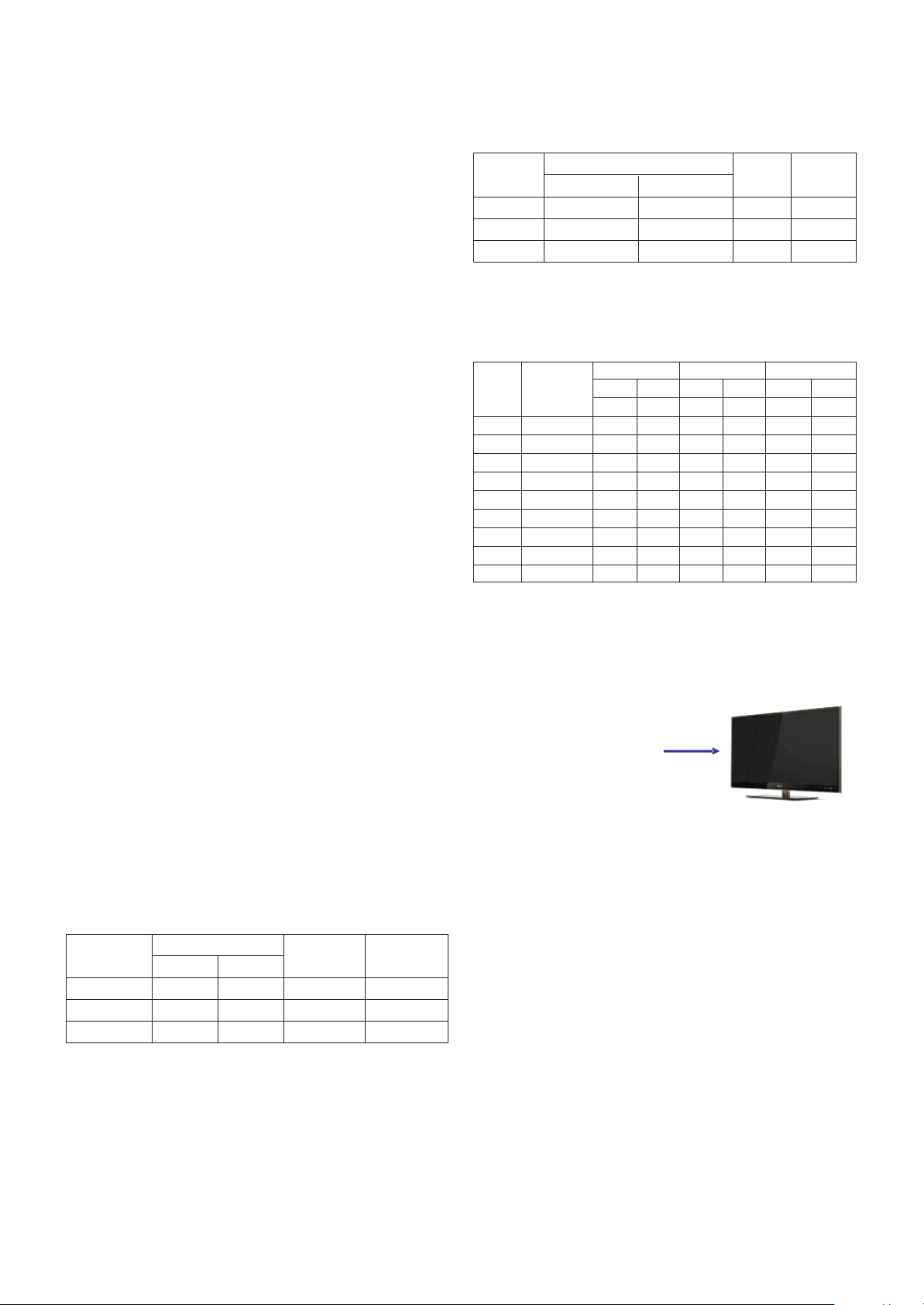
5. Component Video Input (Y, CB/PB, CR/PR)
No.
Specification
Remark
Resolution H-freq(kHz) V-freq(Hz)
1. 720x480 15.73 60.00 SDTV,DVD 480i
2. 720x480 15.63 59.94 SDTV,DVD 480i
3. 720x480 31.47 59.94 480p
4. 720x480 31.50 60.00 480p
5. 720x576 15.625 50.00 SDTV,DVD 625 Line
6. 720x576 31.25 50.00 HDTV 576p
7. 1280x720 45.00 50.00 HDTV 720p
8. 1280x720 44.96 59.94 HDTV 720p
9. 1280x720 45.00 60.00 HDTV 720p
10. 1920x1080 31.25 50.00 HDTV 1080i
11. 1920x1080 33.75 60.00 HDTV 1080i
12. 1920x1080 33.72 59.94 HDTV 1080i
13. 1920x1080 56.250 50 HDTV 1080p
14. 1920x1080 67.5 60 HDTV 1080p
No.
Specification
Proposed Remarks
Resolution H-freq(kHz) V-freq(Hz) Pixel Clock(MHz)
1. 720*400 31.468 70.08 28.321 For only DOS mode
2. 640*480 31.469 59.94 25.17 VESA Input 848*480 60 Hz, 852*480 60 Hz
-> 640*480 60 Hz Display
3. 800*600 37.879 60.31 40.00 VESA
4. 1024*768 48.363 60.00 65.00 VESA(XGA)
5. 1360*768 47.72 59.8 84.75 WXGA
6. 1920*1080 66.587 59.93 138.625 WUXGA FHD model
6. RGB (PC)
Page 7

- 7 -
LGE Internal Use OnlyCopyright © 2011 LG Electronics. Inc. All rights reserved.
Only for training and service purposes
7. HDMI Input
(1) DTV Mode
No. Resolution H-freq(kHz) V-freq.(Hz) Pixel clock(MHz) Proposed Remark
1. 720*400 31.468 70.08 28.321 HDCP
2. 640*480 31.469 59.94 25.17 VESA HDCP
3. 800*600 37.879 60.31 40.00 VESA HDCP
4. 1024*768 48.363 60.00 65.00 VESA(XGA) HDCP
5. 1360*768 47.72 59.8 84.75 WXGA HDCP
6. 1280*1024 63.595 60.0 108.875 SXGA HDCP/FHD model
7. 1920*1080 67.5 60.00 138.625 WUXGA HDCP/FHD model
(2) PC Mode
No. Resolution H-freq(kHz) V-freq.(Hz) Pixel clock(MHz) Proposed Remark
1. 720*480 31.469 /31.5 59.94 /60 27.00/27.03 SDTV 480P
2. 720*576 31.25 50 54 SDTV 576P
3. 1280*720 37.500 50 74.25 HDTV 720P
4. 1280*720 44.96 /45 59.94 /60 74.17/74.25 HDTV 720P
5. 1920*1080 33.72 /33.75 59.94 /60 74.17/74.25 HDTV 1080I
6. 1920*1080 28.125 50.00 74.25 HDTV 1080I
7. 1920*1080 26.97 /27 23.97 /24 74.17/74.25 HDTV 1080P
8. 1920*1080 33.716 /33.75 29.976 /30.00 74.25 HDTV 1080P
9. 1920*1080 56.250 50 148.5 HDTV 1080P
10. 1920*1080 67.43 /67.5 59.94 /60 148.35/148.50 HDTV 1080P
Page 8

- 8 -
LGE Internal Use OnlyCopyright © 2011 LG Electronics. Inc. All rights reserved.
Only for training and service purposes
8. 3D Mode
(1) HDMI Input (1.4a)
No. Resolution H-freq(kHz) V-freq.(Hz) Pixel clock(MHz) Proposed 3D input proposed mode
1 1920*1080 53.95 / 54 23.98 / 24 148.35/148.5 HDTV 1080P Frame packing
2 1280*720 89.9 / 90 59.94/60 148.35/148.5 HDTV 720P Frame packing
3 1280*720 75 50 148.5 HDTV 720P Frame packing
4 1920*1080 67.5 60 148.5 HDTV 1080P Side by Side(half), Top and bottom
5 1920*1080 56.3 50 148.5 HDTV 1080P Side by Side(half), Top and bottom
6 1280*720 45 60 74.25 HDTV 720P Side by Side(half), Top and Bottom
7 1280*720 37.5 50 74.25 HDTV 720P Side by Side(half), Top and Bottom
8 1920*1080 33.7 60 74.25 HDTV 1080i Side by Side(half), Top and Bottom
9 1920*1080 28.1 50 74.25 HDTV 1080i Side by Side(half), Top and Bottom
10 1920*1080 27 24 74.25 HDTV 1080P Side by Side(half), Top and Bottom
11 1920*1080 33.7 30 89.1 HDTV 1080P Side by Side(half), Top and Bottom
No. Resolution H-freq(kHz) V-freq.(Hz) Pixel clock(MHz) Proposed 3D input proposed mode
1 1280*720 45.00 60.00 74.25 HDTV 720P Side by Side, Top & Bottom
2 1280*720 37.500 50 74.25 HDTV 720P Side by Side, Top & Bottom
3 1920*1080 33.75 60.00 74.25 HDTV 1080I Side by Side, Top & Bottom
4 1920*1080 28.125 50.00 74.25 HDTV 1080I Side by Side, Top & Bottom
5 1920*1080 27.00 24.00 74.25 HDTV 1080P Side by Side, Top & Bottom,
Checkerboard
6 1920*1080 33.75 30.00 74.25 HDTV 1080P Side by Side, Top & Bottom,
Checkerboard
7 1920*1080 67.50 60.00 148.5 HDTV 1080P Side by Side, Top & Bottom,
Checkerboard, Single Frame Sequential
8 1920*1080 56.250 50 148.5 HDTV 1080P Side by Side, Top & Bottom,
Checkerboard, Single Frame Sequential
(2) HDMI Input (1.3)
(3) RF 3D Input(DTV)
No. Resolution H-freq(kHz) V-freq.(Hz) Pixel clock(MHz) Proposed 3D input proposed mode
1 1280*720 37.500 50 74.25 HDTV 720P Side by Side, Top & Bottom
2 1920*1080 28.125 50 74.25 HDTV 1080I Side by Side, Top & Bottom
(4) USB Input
No. Resolution H-freq(kHz) V-freq.(Hz) Pixel clock(MHz) 3D input proposed mode Proposed
1 1920*1080 33.75 30.000 74.25 Side by Side HDTV 1080P
Top & Bottom
Checkerboard
Page 9
- 9 -
LGE Internal Use OnlyCopyright © 2011 LG Electronics. Inc. All rights reserved.
Only for training and service purposes
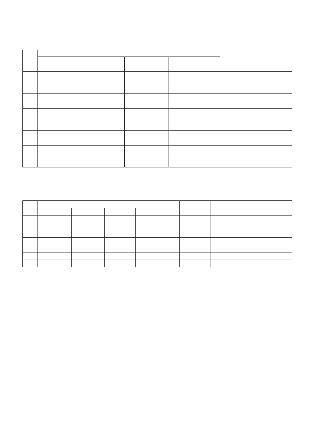
(7) 3D Input mode
(5) RGB-PC Input
No. Resolution H-freq(kHz) V-freq.(Hz) Pixel clock(MHz) Proposed 3D input proposed mode
1 1920*1080 67.5 60 148.5 HDTV 1080P Side by Side, Top & Bottom
(6) DLNA
No. Resolution H-freq(kHz) V-freq.(Hz) Pixel clock(MHz) Proposed 3D input proposed mode
1 1920*1080 33.75 30 HDTV 1080P Side by Side, Top & Bottom,
Checkerboard
No. Side by Side Top & Bottom Checkerboard Single Frame Sequential Frame Packing
1.
RL
L
Page 10

- 10 -
LGE Internal Use OnlyCopyright © 2011 LG Electronics. Inc. All rights reserved.
Only for training and service purposes
ADJUSTMENT INSTRUCTION
1. Application Range
This specification sheet is applied to all of the LED LCD TV
with LD12C chassis.
2. Designation
(1) Because this is not a hot chassis, it is not necessary to use
an isolation transformer. However, the use of isolation
transformer will help protect test instrument.
(2) Adjustment must be done in the correct order.
(3) The adjustment must be performed in the circumstance of
25 ºC ± 5 ºC of temperature and 65 % ± 10 % of relative
humidity if there is no specific designation.
(4) The input voltage of the receiver must keep AC 100-240
V~ 50 / 60Hz.
(5) The receiver must be operated for about 5 minutes prior to
the adjustment when module is in the circumstance of over
15.
In case of keeping module is in the circumstance of 0 °C, it
should be placed in the circumstance of above 15 °C for 2
hours
In case of keeping module is in the circumstance of below 20 °C, it should be placed in the circumstance of above 15
°C for 3 hours.
[Caution]
When still image is displayed for a period of 20 minutes or
longer (especially where W/B scale is strong. Digital pattern
13ch and/or Cross hatch pattern 09ch), there can some
afterimage in the black level area.
3. Automatic Adjustment
3.1. ADC Adjustment
(1) Overview
ADC adjustment is needed to find the optimum black level
and gain in Analog-to-Digital device and to compensate
RGB deviation.
* If Adjust ADC is “OTP”, It doesn’t need ADC adjustment.
(GP3-BCM)
(2) Equipment & Condition
1) Jig (RS-232C protocol)
2) MSPG-925 Series Pattern Generator(MSPG-925FA,
pattern - 65)
- Resolution : 480i Comp1
1080P Comp1
1920*1080 RGB
- Pattern : Horizontal 100% Color Bar Pattern
- Pattern level : 0.7±0.1 Vp-p
- Image
(3) Adjustment
1) Adjustment method
- Using RS-232, adjust items in the other shown in
“3.1.(3).3)”
2) Adj. protocol
Ref.) ADC Adj. RS232C Protocol_Ver1.0
3) Adj. order
- aa 00 00 [Enter ADC adj. mode]
- xb 00 04 [Change input source to Component1(480i&1080p)]
- ad 00 10 [Adjust 480i Comp1]
- xb 00 06 [Change input source to RGB(1024*768)]
- ad 00 10 [Adjust 1024*768 RGB]
- ad 00 90 End adj.
3.2. MAC Address
(1) Equipment & Condition
- Play file: Serial.exe
- MAC Address edit
- Input Start / End MAC address
(2) Download method
1) Communication Prot connection
Connect: PCBA Jig-> RS-232C Port== PC-> RS-232C Port
Protocol Command Set ACK
Enter adj. mode aa 00 00 a 00 OK00x
Source change xb 00 40 b 00 OK40x (Adjust 480i, 1080p Comp1 )
xb 00 60 b 00 OK60x (Adjust 1920*1080 RGB)
Begin adj. ad 00 10
Return adj. result OKx (Case of Success)
NGx (Case of Fail)
Read adj. data (main) (main)
ad 00 20 000000000000000000000000007c007b006dx
(sub) (Sub)
ad 00 21 000000070000000000000000007c00830077x
Confirm adj. ad 00 99 NG 03 00x (Fail)
NG 03 01x (Fail)
NG 03 02x (Fail)
OK 03 03x (Success)
End adj. aa 00 90 a 00 OK90x
PCBA
PC(RS-232C)
RS-232C Po rt
Page 11

- 11 -
LGE Internal Use OnlyCopyright © 2011 LG Electronics. Inc. All rights reserved.
Only for training and service purposes
2) MAC Address Download
- Com 1,2,3,4 and 115200(Baud rate)
- Port connection button click(1)
- Load button click(2) for MAC Address write.
- Start MAC Address write button(3)
- Check the OK Or NG
3.3. LAN Inspection
(1) Equipment & Condition
A Each other connection to LAN Port of IP Hub and Jig
(2) LAN inspection solution
A LAN Port connection with PCB
A Network setting at MENU Mode of TV
A setting automatic IP
A Setting state confirmation
-> If automatic setting is finished, you confirm IP and
MAC Address.
3.4. LAN PORT INSPECTION(PING TEST)
Connect SET -> LAN port == PC -> LAN Port
(1) Equipment setting
1) Play the LAN Port Test PROGRAM.
2) Input IP set up for an inspection to Test
Program.
*IP Number : 12.12.2.2
(2) LAN PORT inspection (PING TEST)
1) Play the LAN Port Test Program.
2) Connect each other LAN Port Jack.
3) Play Test (F9) button and confirm OK Message.
4) Remove LAN CABLE
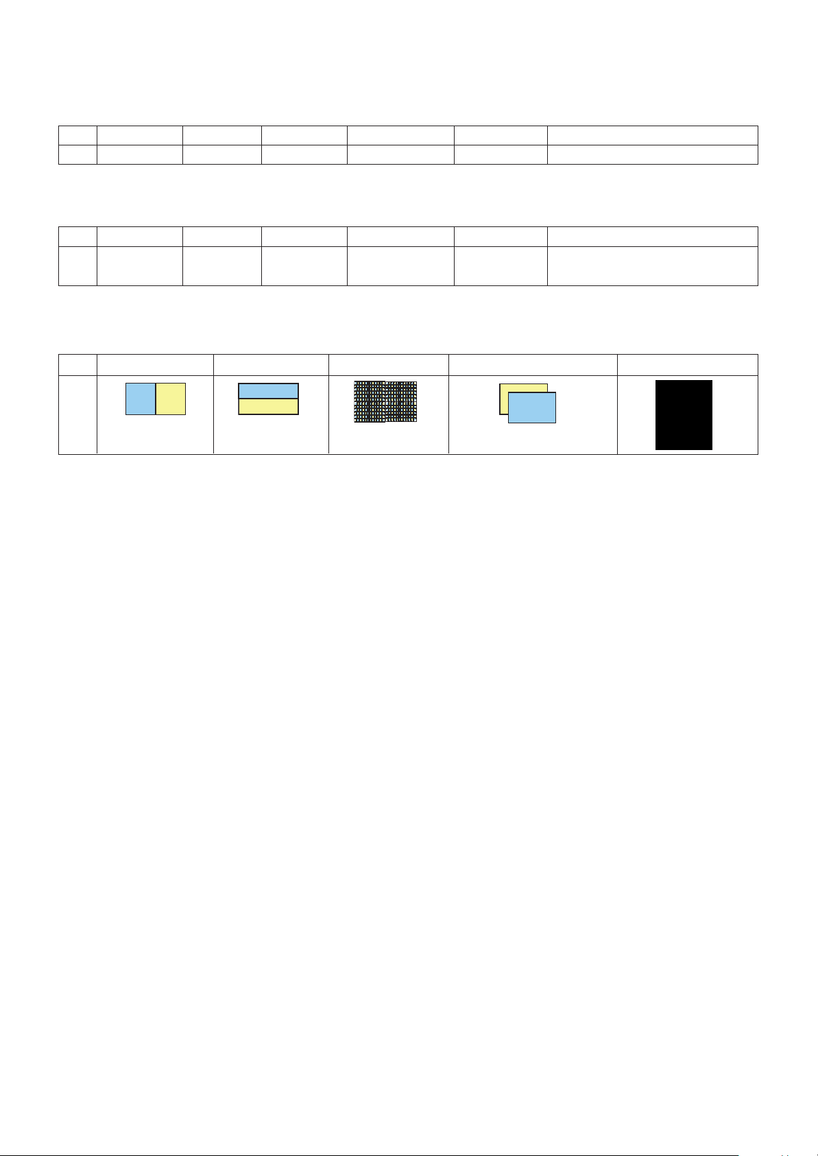
3.5. Model name & Serial number Download
(1) Model name & Serial number D/L
A Press “Power on” key of service remote control.
(Baud rate : 115200 bps)
A Connect RS232 Signal Cable to RS-232 Jack.
A Write Serial number by use RS-232.
A Must check the serial number at Instart menu.
(2) Method & notice
A. Serial number D/L is using of scan equipment.
B. Setting of scan equipment operated by Manufacturing
Technology Group.
C.Serial number D/L must be conformed when it is
produced in production line, because serial number D/L
is mandatory by D-book 4.0
SET PC
Page 12

- 12 -
LGE Internal Use OnlyCopyright © 2011 LG Electronics. Inc. All rights reserved.
Only for training and service purposes
* Manual Download (Model Name and Serial Number)
If the TV set is downloaded by OTA or service man,
sometimes model name or serial number is initialized.(Not
always)
There is impossible to download by bar code scan, so It
need Manual download.
a. Press the ‘instart’ key of ADJ remote control.
b. Go to the menu ‘5.Model Number D/L’ like below photo.
c. Input the Factory model name(ex 42LW950-ZA) or Serial
number like photo.
d. Check the model name Instart menu -> Factory name
displayed (ex 42LW750S-ZA)
e. Check the Diagnostics (DTV country only) -> Buyer model
displayed (ex 42LW750S-ZA)
3.6. CI+ Key Download method
3.6.1. Download Procedure
(1) Press “Power on” key of a Service Remote control.
(Baud rate : 115200 bps)
(2) Connect RS232-C Signal Cable.
(3) Write CI+ key through RS-232-C.
(4) Check whether the key was downloaded or not at ‘In Start’
menu. (Refer to below).
=> Check the Download to CI+ Key value in LGset.
3.6.2. Check the method of CI+ Key value
(1) check the method on Instart menu
(2) check the method of RS232C Command
1) into the main ass’y mode (RS232 : aa 00 00)
2) check the key download for transmitted command
(RS232 : ci 00 10)
3) result value
- normally status for download : OKx
- abnormally status for download : NGx
3.6.3. Check the method of CI+ Key value (RS232)
1) into the main ass’y mode (RS232 : aa 00 00)
2) Check the method of CI+ key by command (RS232 : ci
00 20)
3) Result value
i 01 OK 1d1852d21c1ed5dcx
3.7. Widevine Key Download method
3.7.1. Widevine key Download
(1) Press "Power on" key of a Service Remote control.
(Baud rate : 115200 bps)
(2) Connect RS232-C Signal Cable.
(3) Write Widevine key through RS-232-C.
(4) Check whether the key was downloaded or not at ‘In Start’
menu. (Refer to below).
=> Check the Download to Widevine Key value in LGset.
3.7.2. check the method of Widevine Key value.
(1) Check the method on Instart menu.
(2) Check the method of RS232C Command.
1) into the main ass’y mode (RS232 : aa 00 00)
2) Check the key download for transmitted command
(RS232 : ci 00 10)
3) result value
- normally status for download : OKx
- abnormally status for download : NGx
-
3.7.3 check the method of Widevine Key value (RS232)
1) into the main ass’y mode (RS232 : aa 00 00)
2) Check the method of Widevine key by command
(RS232 : ci 00 20)
3) result value
i 01 OK 1d1852d21c1ed5dcx
CMD 1 CMD 2 Data 0
AA00
CMD 1 CMD 2 Data 0
CI10
CMD 1 CMD 2 Data 0
AA00
CMD 1 CMD 2 Data 0
CI20
CMD 1 CMD 2 Data 0
CI20
CI+ key Value
CMD 1 CMD 2 Data 0
AA00
CMD 1 CMD 2 Data 0
CI10
CMD 1 CMD 2 Data 0
AA00
Widevine key Value
Page 13
- 13 -
LGE Internal Use OnlyCopyright © 2011 LG Electronics. Inc. All rights reserved.
Only for training and service purposes
3.8. Mac+Widevine+GP3 BCM CI+ download
3.8.1 Connect: PCBA Jig-> RS-232C Port== PC-> RS-232C Port
3.8.2 MAC Address, CI Plus key and Widevine Key write.
11Y LCD TV + MAC + Widevine + GP3_BCM CI Plus
(1) Equipment setting
- Play file: keydownload.exe
- select the download items.(MARLIN)
(2) Communication Prot connection
- Key Write :Com 1,2,3,4 and 115200(Baudrate)
- Barcode : Com 1,2,3,4 and 9600(Baudrate)
(3) Mode check: Online Only
(4) Check the test process: DETECT -> MAC -> CI ->
WIDEVINE
(5) Play: START
(6) Result: Ready, Test, OK or NG
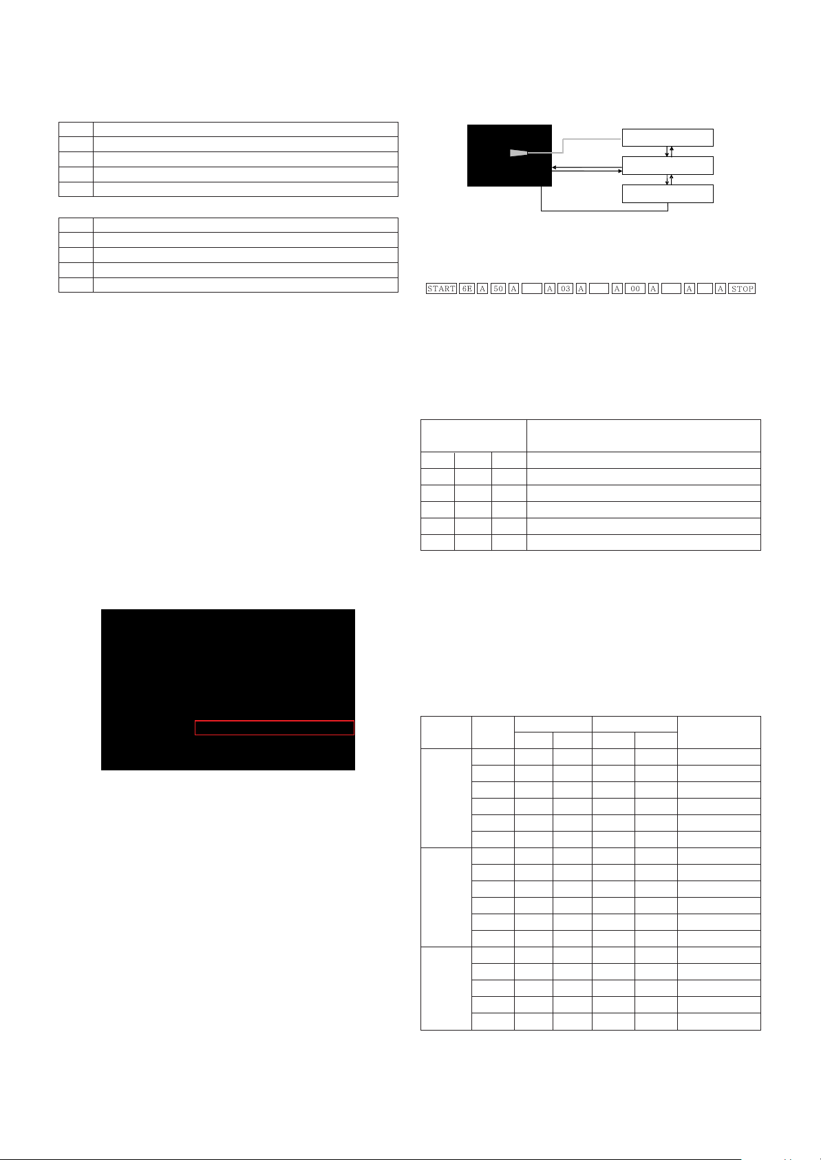
3.9. LNB voltage and 22KHz tone check
- only for DVB-S/S2 model
(1) Test method
1) Press "Power on" key of a service remote control.
(Baud rate : 115200 bps)
2) Connect cable between satellite ANT and test JIG.
3). Connect RS232-C Signal Cable.
4) Write LNB ON control command through RS-232-C.
5) check LED light ‘ON’ at 18 V menu.
6) check LED light ‘ON’ at 22 KHz tone menu.
7) Write LNB OFF control command through RS-232-C.
8) check LED light ‘OFF’ at 18 V menu.
9) check LED light ‘OFF’ at 22 KHz tone menu.
(2) RS-232 command for test LNB
(3) Test result
- After send LNB On command, ‘18V LED’ and ‘22KHz
tone LED’ should be ON.
- After send LNB OFF command, ‘18V LED’ and ‘22KHz
tone LED’ should be OFF.
4. Manual Adjustment
4.1. ADC(GP3) Adjustment
4.1.1. Overview
ADC adjustment is needed to find the optimum black level and
gain in Analog-to-Digital device and to compensate RGB
deviation.
4.1.2. Equipment & Condition
(1) Adjust Remote control
(2) 801GF(802B, 802F, 802R) or MSPG925FA Pattern Generator
- Resolution :
480i, 720*480(MSPG-925FA->Model:209, Pattern:65)-480i
1080p, 1920*1080(MSPG-925FA->Model:225, Pattern:65)-1080p
- Pattern : Horizontal 100 % Color Bar Pattern
- Pattern level: 0.7 ± 0.1 Vp-p
- Image
(3) Must use standard cable
4.1.3. Adjust method
* If Adjust ADC is “OTP”, It doesn’t need ADC adjustment.
(GP3-BM)
(1) ADC 480i, 1080p Comp1
1) Check connected condition of Component 1 cable to the
equipment.
2) Give a 480i, 1080p Mode, Horizontal 100% Color Bar
Pattern to Component 1.
(MSPG-925FA -> Model: 209, Pattern: 65) - 480i
(MSPG-925FA -> Model: 225, Pattern: 65) - 1080p
3) Change input mode as Component 1 and picture mode
as “Standard”.
4) Press the In-start Key on the ADJ remote after at least 1
min of signal reception. Then, select 7. External ADC ->
1. COMP 1080p on the menu. Press enter key. The
adjustment will start automatically.
5) If ADC calibration is successful, “ADC RGB Success” is
displayed.
If ADC calibration is failure, “ADC RGB Fail” is displayed.
6) If ADC calibration is failure, after recheck ADC pattern or
condition retry calibration Error message refer to 5).
(2) ADC 1920*1080 RGB
1) Check connected condition of Component & RGB cable
to the equipment
2) Give a 1920*1080 Mode, 100 % Horizontal Color Bar
Pattern to RGB port.
(MSPG-925 Series -> model: 225 , pattern: 65 )
3) Change input mode as RGB and picture mode as “Standard”.
4) Press the In-start key on the Adjustment remote control
after at least 1 min of signal reception. Then, select 7.
External ADC -> 1. COMP 1080p on the menu. Press
enter key. The adjustment will start automatically.
5) If ADC calibration is successful, “ADC RGB Success” is
displayed.
If ADC calibration is failure, “ADC RGB Fail” is displayed.
6) If ADC calibration is failure, after recheck ADC pattern or
condition retry calibration Error message refer to 5).
PCBA Power ON Check
Result
Play
MARLIN Key : MAC + CI + WIDEVINE
Com Port Check
CI + Key Write
WIDEVINE Key Write
MAC Address Write
Command Set ACK
LNB On [A][I][ ][Set ID][ ][30][Cr] [O][K][x] or NG : [N][G][x]
LNB Off [A][I][ ][Set ID][ ][40][Cr] [O][K][x] or NG : [N][G][x]
Page 14

- 14 -
LGE Internal Use OnlyCopyright © 2011 LG Electronics. Inc. All rights reserved.
Only for training and service purposes
4.2. EDID(The Extended Display Identification
Data)/DDC(Display Data Channel) download
(1) Overview
It is a VESA regulation. A PC or a MNT will display an
optimal resolution through information sharing without any
necessity of user input. It is a realization of “Plug and Play”.
(2) Equipment
- Adjust remote control
- Since embedded EDID data is used, EDID download JIG,
HDMI cable and D-sub cable are not need.
(3) Download method
1) Press ADJ key on the Adjustment remote control, then
select “10.EDID D/L”, By pressing Enter key, enter EDID
D/L menu.
2) Select [Start] button by pressing Enter key, HDMI1/
HDMI2/ HDMI3/ RGB are Writing and display OK or NG.
(4) EDID DATA_3D
A HDMI
A RGB
(5) EDID DATA_2D
A HDMI
A RGB
A Reference
- HDMI1 ~ HDMI4 / RGB
- In the data of EDID, bellows may be different by S/W or
Input mode.
ⓐ Product ID
ⓑ Serial No. : Controlled on product line
ⓒ Month, Year: Controlled on production line:
ex) Monthly : ‘01’ -> ‘01’
Year : ‘2010’ -> ‘14’
ⓓ Model Name(Hex):
ⓔ Checksum: Changeable by total EDID data._3D
ⓔ Checksum: Changeable by total EDID data._2D
D-sub to D-sub DVI-D to HDMI or HDMI to HDMI
For HDMI EDIDFor Analog EDID
0x00 0x01 0x02 0x03 0x04 0x05 0x06 0x07 0x08 0x09 0x0A 0x0B 0x0C 0x0D0x0E 0x0F
0x00 0 FF FF FF FF FF FF 0 1E 6D ⓐⓑ
0x01 ⓒ 1 3 8010 9 780AEE91A3544C9926
0x02 0F 50 54 A1 8 0 71 40 81 C0 81 0 81 80 95 0
0x03 90 40 A9 C0 B3 0 2 3A 80 18 71 38 2D 40 58 2C
0x04 45 0 A0 5A 0 0 0 1E 66 21 50 B0 51 0 1B 30
0x05 40 70 36 0 A0 5A 0 0 0 1E 0 0 0 FD 0 39
0x06 3F 1F 52 10 0 0A 20 20 20 20 20 20 ⓓ
0x07 ⓓ 1 ⓔ1
0x00 2 3 37 F1 4E 10 1F 84 13 5 14 3 2 12 20 21
0x01 22 15 1 26 15 7 50 9 57 7 ⓕ
0x02 ⓕ
0x03 ⓕ E3 5 3 1 1 1D 80 18 71 1C 16 20 58
0x04 2C 25 0 A0 5A 0 0 0 9E 1 1D 0 80 51 D0 1A
0x05 20 6E 88 55 0 A0 5A 0 0 0 1A 2 3A 80 18 71
0x06 38 2D 40 58 2C 45 0 A0 5A 0 0 0 1E 0 0 0
0x07 0 0 0 0 0 0 0 0 0 0 0 0 0 0 0 ⓔ2
0x00 0x01 0x02 0x03 0x04 0x05 0x06 0x07 0x08 0x09 0x0A 0x0B 0x0C 0x0D0x0E 0x0F
0x00 0 FF FF FF FF FF FF 0 1E 6D ⓐⓑ
0x01 ⓒ 1 3 6810 9 780AEE91A3544C9926
0x02 0F 50 54 A1 8 0 71 40 81 C0 81 0 81 80 95 0
0x03 90 40 A9 C0 B3 0 2 3A 80 18 71 38 2D 40 58 2C
0x04 45 0 A0 5A 0 0 0 1E 66 21 50 B0 51 0 1B 30
0x05 40 70 36 0 A0 5A 0 0 0 1E 0 0 0 FD 0 3A
0x06 3E 1E 53 10 0 0A 20 20 20 20 20 20 ⓓ
0x07 ⓓ 0 ⓔ3
0x00 0x01 0x02 0x03 0x04 0x05 0x06 0x07 0x08 0x09 0x0A 0x0B 0x0C 0x0D0x0E 0x0F
0x00 0 FF FF FF FF FF FF 0 1E 6D ⓐⓑ
0x01 ⓒ 1 3 6810 9 780AEE91A3544C99 26
0x02 0F 50 54 A1 8 0 71 40 81 C0 81 0 81 80 95 0
0x03 90 40 A9 C0 B3 0 2 3A 80 18 71 38 2D 40 58 2C
0x04 45 0 A0 5A 0 0 0 1E 66 21 50 B0 51 0 1B 30
0x05 40 70 36 0 A0 5A 0 0 0 1E 0 0 0 FD 0 3A
0x06 3E 1E 53 10 0 0A 20 20 20 20 20 20 ⓓ
0x07 ⓓ 0 ⓔ3
0x00 0x01 0x02 0x03 0x04 0x05 0x06 0x07 0x08 0x09 0x0A 0x0B 0x0C 0x0D0x0E 0x0F
0x00 0 FF FF FF FF FF FF 0 1E 6D ⓐⓑ
0x01 ⓒ 1 3 80 10 9 780AEE91A3544C9926
0x02 0F 50 54 A1 8 0 71 40 81 C0 81 0 81 80 95 0
0x03 90 40 A9 C0 B3 0 2 3A 80 18 71 38 2D 40 58 2C
0x04 45 0 A0 5A 0 0 0 1E 66 21 50 B0 51 0 1B 30
0x05 40 70 36 0 A0 5A 0 0 0 1E 0 0 0 FD 0 39
0x06 3F 1F 52 10 0 0A 20 20 20 20 20 20 ⓓ
0x07 ⓓ 1 ⓔ1
0x00 2 3 26 F1 4E 10 1F 84 13 5 14 3 2 12 20 21
0x01 22 15 1 26 15 7 50 9 57 7 67 ⓕ
0x02 ⓕ E3 5 3 1 1 1D 80 18 71 1C 16 20 58 2C
0x03 25 0 A0 5A 0 0 0 9E 1 1D 0 80 51 D0 1A 20
0x04 6E 88 55 0 A0 5A 0 0 0 1A 2 3A 80 18 71 38
0x05 2D 40 58 2C 45 0 A0 5A 0 0 0 1E 66 21 50 B0
0x06 51 0 1B 30 40 70 36 0 A0 5A 0 0 0 1E 0 0
0x07 0 0 0 0 0 0 0 00000000ⓔ2
Model Name HEX EDID Table DDC Function
ALL 0001 0100 Analog
0001 0100 Digital
MODEL MODEL NAME(HEX)
all 00 00 00 FC 00 4C 47 20 54 56 0A 20 20 20 20 20 20 20
INPUT 1 2 3
HDMI1 7F CB X
HDMI2 7F BB X
HDMI3 7F AB X
HDMI4 7F 9B X
RGB X X 98
INPUT 1 2 3
HDMI1 7F D9 X
HDMI2 7F C9 X
HDMI3 7F B9 X
HDMI4 7F A9 X
RGB X X 98
Page 15
- 15 -
LGE Internal Use OnlyCopyright © 2011 LG Electronics. Inc. All rights reserved.
Only for training and service purposes
ⓕ Vendor Specific(HDMI)_3D
ⓕ Vendor Specific(HDMI)_2D
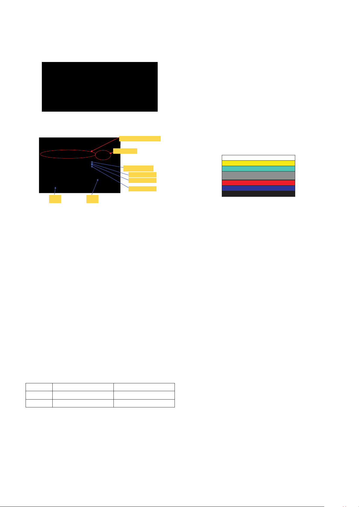
4.3. White Balance Adjustment
4.3.1 Overview
(1) W/B adj. Objective & How-it-works
(2) Objective: To reduce each Panel’s W/B deviation
(3) How-it-works : When R/G/B gain in the OSD is at 192, it
means the panel is at its Full Dynamic Range. In order to
prevent saturation of Full Dynamic range and data, one of
R/G/B is fixed at 192, and the other two is lowered to find
the desired value.
(4) Adj. condition : normal temperature
1) Surrounding Temperature : 25 ºC ± 5 ºC
2) Warm-up time: About 5 Min
3) Surrounding Humidity : 20 % ~ 80 %
* Before White balance adjustment, Keep power on status.
don’t power off.
* ALEF Header(Module with T-con) supplied as SKD has
White Balance data. (White balance data is stored in
EEPROM of the T-con Board)
It doesn’t need to adjust White balance if “3. Adjust White
Balance” is OK as figure below.
4.3.2 Equipment
1) Color Analyzer: CA-210 (LED Module : CH 14)
2) Adj. Computer(During auto adj., RS-232C protocol is needed)
3) Adjust Remote control
4) Video Signal Generator MSPG-925F 720p/216-Gray
(Model:204, Pattern:80IRE)
-> Only when internal pattern is not available
A Color Analyzer Matrix should be calibrated using CS-1000
4.3.3. Equipment connection MAP
4.3.4. Adj. Command (Protocol)
<Command Format>
- LEN: Number of Data Byte to be sent
- CMD: Command
- VAL: FOS Data value
- CS: Checksum of sent data
- A: Acknowledge
Ex) [Send: JA_00_DD] / [Ack: A_00_okDDX]
A RS-232C Command used during auto-adj.
Ex) wb 00 00 -> Begin white balance auto-adj.
wb 00 10 -> Gain adj.
ja 00 ff -> Adj. data
jb 00 c0
...
...
wb 00 1f -> Gain adj. completed
*(wb 00 20(Start), wb 00 2f(completed)) -> Off-set adj.
wb 00 ff -> End white balance auto-adj.
A Adj. Map
Color Analyzer
Comp uter
Pattern Generator
RS- 232C
RS-232C
RS-232C
Probe
Signal Source
* If TV internal pattern is used, not needed
LEN CMD VAL
CS
RS-232C COMMAND Explanation
[CMD ID DATA]
wb 00 00 Begin White Balance adj.
wb 00 10 Gain adj.(internal white pattern)
wb 00 1f Gain adj. completed
wb 00 20 Offset adj.(internal white pattern)
wb 00 2f Offset adj. completed
wb 00 ff End White Balance adj.(Internal pattern disappears)
ITEM Command Data Range(Hex.) Default(Decimal)
Cmd 1 Cmd 2 Min Max
Cool R-Gain j g 00 C0
G-Gain j h 00 C0
B-Gain j i 00 C0
R-Cut
G-Cut
B-Cut
Medium R-Gain j a 00 C0
G-Gain j b 00 C0
B-Gain j c 00 C0
R-Cut
G-Cut
B-Cut
Warm R-Gain j d 00 C0
G-Gain j e 00 C0
B-Gain j f 00 C0
R-Cut
G-Cut
INPUT MODEL NAME(HEX)
HDMI1 78 03 0C 00 10 00 B8 2D 20 C0 0E 01 40 0A 3C 08 10 18 10 98 10 58 10 38 10
HDMI2 78 03 0C 00 20 00 B8 2D 20 C0 0E 01 40 0A 3C 08 10 18 10 98 10 58 10 38 10
HDMI3 78 03 0C 00 30 00 B8 2D 20 C0 0E 01 40 0A 3C 08 10 18 10 98 10 58 10 38 10
HDMI4 78 03 0C 00 40 00 B8 2D 20 C0 0E 01 40 0A 3C 08 10 18 10 98 10 58 10 38 10
INPUT MODEL NAME(HEX)
HDMI1 67 03 0C 00 10 00 B8 2D
HDMI2 67 03 0C 00 20 00 B8 2D
HDMI3 67 03 0C 00 30 00 B8 2D
HDMI4 67 03 0C 00 40 00 B8 2D
Page 16
- 16 -
LGE Internal Use OnlyCopyright © 2011 LG Electronics. Inc. All rights reserved.
Only for training and service purposes
4.3.5. Adjustment method
(1) Auto adjustment method
1) Set TV in adj. mode using POWER ON key.
2) Zero calibrate probe then place it on the center of the
Display.
3) Connect Cable (RS-232C)
4) Select mode in adj. Program and begin adjustment.
5) When adjustment is complete (OK Sign), check adj.
status pre mode.(Warm, Medium, Cool)
6) Remove probe and RS-232C cable to complete adj.
A W/B Adj. must begin as start command “wb 00 00” , and
finish as end command “wb 00 ff”, and Adj. offset if need.
(2) Manual adjustment method
1) Set TV in Adjustment mode using POWER ON
2) Zero Calibrate the probe of Color Analyzer, then place it on
the center of LCD module within 10 cm of the surface.
3) Press ADJ key -> EZ adjust using adjustment R/C -> 7.
White-Balance then press the cursor to the right key(G).
(When key(G) is pressed 216 Gray internal pattern will
be displayed)
4) One of R Gain / G Gain / B Gain should be fixed at 192,
and the rest will be lowered to meet the desired value.
5) Adj. is performed in COOL, MEDIUM, WARM 3 modes
of color temperature.
A If internal pattern is not available, use RF input. In EZ
Adj. menu 7.White Balance, you can select one of 2
Test-pattern: ON, OFF. Default is inner(ON). By
selecting OFF, you can adjust using RF signal in 216
Gray pattern.
A Adj. condition and cautionary items
1) Lighting condition in surrounding area
Surrounding lighting should be lower 10 lux. Try to
isolate adj. area into dark surrounding.
2) Probe location : Color Analyzer(CA-210) probe should
be within 10 cm and perpendicular of the module
surface (80° ~ 100°)
3) Aging time
- After Aging Start, Keep the Power ON status during 5
Minutes.
- In case of LCD, Back-light on should be checked
using no signal or Full-white pattern.
4.3.6. Reference(White Balance Adj. coordinate and
temperature)
A Luminance : 204 Gray
A Standard color coordinate and temperature using CS-1000
(over 26 inch)
A Standard color coordinate and temperature using CA-210
(CH 14)
4.3.7. White balance table
A Module change color coordinate because of aging time.
A Apply under the color coordinate table, for compensated
aging time.
4.4. Wireless function check
Step 1) Connect set and Dongle of Wireless to Cable of HDMI
& TTA 20Pin
Step 2) At OSD of SET, check the message like Fig.3
Step 3) Detach Cable of Wireless Dongle
Mode Color Coordination Temp ∆UV
xy
COOL 0.269 0.273 13000 K 0.0000
MEDIUM 0.285 0.293 9300 K 0.0000
WARM 0.313 0.329 6500 K 0.0000
Mode Color Coordination Temp ∆UV
xy
COOL 0.269 ± 0.002 0.273 ± 0.002 13000 K 0.0000
MEDIUM 0.285 ± 0.002 0.293 ± 0.002 9300 K 0.0000
WARM 0.313 ± 0.002 0.329 ± 0.002 6500 K 0.0000
GP2 Aging Time Cool Medium Warm
(Min.) X Y X Y X Y
269 273 285 293 313 329
1 0-2 279 288 295 308 319 338
2 3-5 278 286 294 306 318 336
3 6-9 277 285 293 305 317 335
4 10-19 276 283 292 303 316 333
5 20-35 274 280 290 300 314 330
6 36-49 272 277 288 297 312 327
7 50-79 271 275 287 295 311 325
8 80-149 270 274 286 294 310 324
9 Over 150 269 273 285 293 309 323
Fig. 1
<Dongle>
Fig. 3 Connect the Dongle
(Dongle Connection Display)
Fig. 2
<Wireless Ready Set>
Connect
Page 17

- 17 -
LGE Internal Use OnlyCopyright © 2011 LG Electronics. Inc. All rights reserved.
Only for training and service purposes
4.5. EYE-Q function check
Step 1) Turn on TV
Step 2) Press EYE key of Adj. R/C
Step 3) Cover the Eye Q II sensor on the front of the using
your hand and wait for 6 seconds
Step 4) Confirm that R/G/B value is lower than 10 of the “Raw
Data (Sensor data, Back light)”. If after 6 seconds,
R/G/B value is not lower than 10, replace Eye Q II
sensor.
Step 5) Remove your hand from the Eye Q II sensor and wait
for 6 seconds.
Step 6) Confirm that “ok” pop up. If change is not seen,
replace Eye Q II sensor.
4.6. Local Dimming Function Check
(1) Turn on TV.
(2) At the Local Dimming mode, module Edge Backlight
moving Top to Bottom Back light of IOP module moving.
(3) Confirm the Local Dimming mode.
(4) Press “exit” key
4.7. Magic Motion Remote control test
- Equipment : RF Remote control for test, IR-KEY-Code
Remote control for test
- You must confirm the battery power of RF-Remote control
before test.(recommend that change the battery per every lot)
- Sequence (test)
1) if you select the ‘start key(Mute)’ on the controller, you can
pairing with the TV SET.
2) You can check the cursor on the TV Screen, when select
the ‘OK’ key on the controller.
3) You must remove the pairing with the TV Set by select
‘Vol+(STOP)’ key on the controller.
4.8. 3D function test
(Pattern Generator MSHG-600, MSPG-6100 [Support HDMI 1.4])
* HDMI mode No. 872, pattern No. 83)
1) Please input 3D test pattern like below
2) When 3D OSD appear automatically, then select OK key.
3) Don’t wear a 3D Glasses, Check the picture like below.
4.9. LNB voltage and 22 KHz tone check
(only for DVB-S/S2 model)
(1) Test method
1) Set TV in Adj. mode using POWER ON.
2) Connect cable between satellite ANT and test JIG.
3) Press Yellow Key (ETC+SWAP) in Adj Remote control to
make LNB on.
4) check LED light ‘ON’ at 18V menu.
5) check LED light ‘ON’ at 22KHz tone menu.
6) Press Blue Key (ETC+PIP INPUT) in Adj Remote control
to make LNB off.
7) Check LED light ‘OFF’ at 18 V menu.
8) Check LED light ‘OFF’ at 22 KHz tone menu.
(2) Test result
- After press LNB On key, ‘18 V LED’ and ‘22 KHz tone
LED’ should be ON.
- After press LNB OFF key, ‘18 V LED’ and ‘22 KHz tone
LED’ should be OFF.
Page 18

- 18 -
LGE Internal Use OnlyCopyright © 2011 LG Electronics. Inc. All rights reserved.
Only for training and service purposes
4.10. Option selection per country
(1) Overview
- Option selection is only done for models in Non-EU.
- Applied model: LD03D/03E Chassis applied EU model.
(2) Method
1) Press ADJ key on the Adj. Remote Control, then select
Country Group Menu.
2) Depending on destination, select Country Group Code
04 or Country Group EU then on the lower Country
option, select US, CA, MX. Selection is done using +, or
GF KEY.
4.11. Tool Option selection
- Method : Press Adj. key on the Adj. Remote Control, then
select Tool option.
4.12. Ship-out mode check(In-stop)
After final inspection, press IN-STOP key of the Adj. R/C and
check that the unit goes to Stand-by mode.
5. GND and Internal Pressure check
5.1. Method
1) GND & Internal Pressure auto-check preparation
- Check that Power Cord is fully inserted to the SET.
(If loose, re-insert)
2) Perform GND & Internal Pressure auto-check
- Unit fully inserted Power cord, Antenna cable and A/V
arrive to the auto-check process.
- Connect D-terminal to AV JACK TESTER
- Auto CONTROLLER(GWS103-4) ON
- Perform GND TEST
- If NG, Buzzer will sound to inform the operator.
- If OK, changeover to I/P check automatically.
(Remove CORD, A/V form AV JACK BOX)
- Perform I/P test
- If NG, Buzzer will sound to inform the operator.
- If OK, Good lamp will lit up and the stopper will allow the
pallet to move on to next process.
5.2. Checkpoint
• TEST voltage
- GND: 1.5 KV/min at 100 mA
- SIGNAL: 3 KV/min at 100 mA
• TEST time: 1 second
• TEST POINT
- GND TEST = POWER CORD GND & SIGNAL CABLE
METAL GND
- Internal Pressure TEST = POWER CORD GND & LIVE &
NEUTRAL
• LEAKAGE CURRENT: At 0.5 mArms
6. Audio
Measurement condition:
1. RF input: Mono, 1 KHz sine wave signal, 100 % Modulation
2. CVBS, Component: 1 KHz sine wave signal 0.4 Vrms
3. RGB PC: 1 KHz sine wave signal 0.7 Vrms
7. USB S/W Download (option, Service only)
1) Put the USB Stick to the USB socket.
2) Automatically detecting update file in USB Stick.
- If your downloaded program version in USB Stick is Low,
it didn’t work. But your downloaded version is High, USB
data is automatically detecting.
3) Show the message “Copying files from memory”.
4) Updating is starting.
5) Updating Completed, The TV will restart automatically
6) If your TV is turned on, check your updated version and
Tool option. (explain the Tool option, next stage)
* If downloading version is more high than your TV have, TV
can lost all channel data. In this case, you have to channel
recover. if all channel data is cleared, you didn’t have a
DTV/ATV test on production line.
* After downloading, have to adjust TOOL OPTION again.
1) Push "IN-START" key in service remote control.
2) Select "Tool Option 1" and push “OK” key.
3) Push in the number.(Each model has their number.)
No. Item Min. Typ. Max. Unit
1. Audio practical max 9 10 12 W EQ Off
Output, L/R AVL Off
(Distortion=10 % 0.5 Vrms Clear Voice Off
max Output)
2. Speaker (8 Ω 9 10.0 12.0 W EQ On
Impedance) AVL On
Clear Voice On
Page 19

- 19 -
LGE Internal Use OnlyCopyright © 2011 LG Electronics. Inc. All rights reserved.
Only for training and service purposes
BLOCK DIAGRAM
Page 20
- 20 -
LGE Internal Use OnlyCopyright LG Electronics. Inc. All rights reserved.
Only for training and service purposes
300
200
530
710
540
400
521
LV 1
LV 2
810
510
120
A10
A21
A5
A2
AG1
500
910
700
900
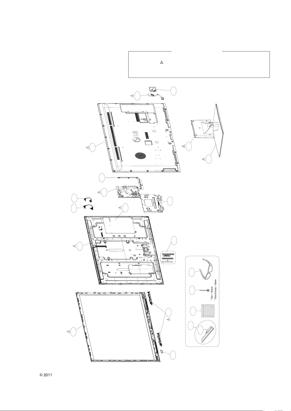
EXPLODED VIEW
Many electrical and mechanical parts in this chassis have special safety-related characteristics. These
parts are identified by in the Schematic Diagram and EXPLODED VIEW.
It is essential that these special safety parts should be replaced with the same components as
recommended in this manual to prevent X-RADIATION, Shock, Fire, or other Hazards.
Do not modify the original design without permission of manufacturer.
IMPORTANT SAFETY NOTICE
Page 21

NAND FLASH MEMORY 8Gbit
Copyright © 2011 LG Electronics. Inc. All rights reserved.
Only for training and service purposes
LGE Internal Use Only
+3.3V_Normal
NC_1
1
NC_2
2
NC_3
3
NC_4
4
NC_5
5
NC_6
6
RY/BY
7
RE
8
CE
9
NC_7
10
NC_8
11
VCC_1
12
VSS_1
13
NC_9
14
NC_10
15
CLE
16
ALE
17
WE
18
WP
19
NC_11
20
NC_12
21
NC_13
22
NC_14
23
NC_15
24
LGE35230(BCM35230KFSBG)
B5
C5
A4
B4
A3
B3
A2
B2
W2
V4
W4
V3
V2
D13
E6
R106
3K
IC101
BCM_WITHOUT_CAP
HDMI0_CLKN
HDMI0_CLKP
HDMI0_D0N
HDMI0_D0P
HDMI0_D1N
HDMI0_D1P
HDMI0_D2N
HDMI0_D2P
CEC
DDC0_SCL
DDC0_SDA
HDMI0_HTPLG_IN
HDMI0_HTPLG_OUT
HDMI0_ARC
HDMI0_RESREF
LT0VCAL_MONITOR
NAND_RBb
NAND_REb
NAND_CEb
NAND_CEb2
NAND_CLE
NAND_ALE
R101
4.7K
FLASH_WP
R105
4.7K
NAND_WEb
R104
4.7K
R195
4.7K
Write Protection
- High : Normal Operation
- Low : Write Protection
+3.3V_Normal
R107 2.7K
R148
+3.3V_Normal
R103
4.7K
HDMI_CLKHDMI_CLK+
HDMI_RX0HDMI_RX0+
HDMI_RX1HDMI_RX1+
HDMI_RX2HDMI_RX2+
HDMI_ARC
16Gbit
R149 0
16Gbit
0
C102
4700pF
C101
0.1uF
OPT
IC102
TC58DVG3S0ETA00
NAND_8Gbit
TXOUT0_L0N
TXOUT0_L0P
TXOUT0_L1N
TXOUT0_L1P
TXOUT0_L2N
TXOUT0_L2P
TXCLK_LN
TXCLK_LP
TXOUT0_L3N
TXOUT0_L3P
TXOUT0_L4N
TXOUT0_L4P
TXOUT0_U0N
TXOUT0_U0P
TXOUT0_U1N
TXOUT0_U1P
TXOUT0_U2N
TXOUT0_U2P
TXCLK_UN
TXCLK_UP
TXOUT0_U3N
TXOUT0_U3P
TXOUT0_U4N
TXOUT0_U4P
TXOUT1_L0N
TXOUT1_L0P
TXOUT1_L1N
TXOUT1_L1P
TXOUT1_L2N
TXOUT1_L2P
TXCLK1_LN
TXCLK1_LP
TXOUT1_L3N
TXOUT1_L3P
TXOUT1_L4N
TXOUT1_L4P
TXOUT1_U0N
TXOUT1_U0P
TXOUT1_U1N
TXOUT1_U1P
TXOUT1_U2N
TXOUT1_U2P
TXCLK1_UN
TXCLK1_UP
TXOUT1_U3N
TXOUT1_U3P
TXOUT1_U4N
TXOUT1_U4P
GPIO_BL_ON
BL_PWM/GPIO
AE27
AE28
AF27
AF28
AG27
AG28
AE26
AF26
AH27
AG26
AF25
AE25
AH26
AG25
AE24
AD24
AH25
AF24
AE23
AD23
AG24
AF23
AC22
AD22
AG23
AH23
AE22
AE21
AF22
AH22
AG22
AF21
AG21
AF20
AD21
AC21
AG20
AH20
AD19
AE19
AF19
AH19
AE18
AD18
AG19
AF18
AG18
AF17
AC18
AH16
AG16
16Gbit
IC102-*1
TH58DVG4S0ETA20
SDA0_3.3V
SCL0_3.3V
SCL2_3.3V
SDA2_3.3V
R199 22
R197 22
48
47
46
45
44
43
42
41
40
39
38
37
36
35
34
33
32
31
30
29
28
27
26
25
NC_26
NC_25
NC_24
NC_23
I/O8
I/O7
I/O6
I/O5
NC_22
PSL
NC_21
VCC_2
VSS_2
NC_20
NC_19
NC_18
I/O4
I/O3
I/O2
I/O1
NC_17
NC_16
NC_15
NC_14
+3.3V_Normal
NC_1
1
NC_28
48
NC_27
47
NC_26
46
NC_25
45
I/O8
NAND_DATA[7]
44
I/O7
NAND_DATA[6]
43
I/O6
42
NAND_DATA[5]
I/O5
41
NAND_DATA[4]
NC_24
40
39
38
37
36
35
34
33
32
31
30
29
28
27
26
25
PSL
NC_23
VCC_2
VSS_2
NC_22
NC_21
NC_20
I/O4
I/O3
I/O2
I/O1
NC_19
NC_18
NC_17
NC_16
16Gbit
R151
+3.3V_Normal
C104 10uF
NAND_DATA[3]
NAND_DATA[2]
NAND_DATA[1]
NAND_DATA[0]
TXB4P
TXB4N
TXB3P
TXB3N
TXBCLKP
TXBCLKN
TXB2P
TXB2N
TXB1P
TXB1N
TXB0P
TXB0N
TXA4P
TXA4N
TXA3P
TXA3N
TXACLKP
TXACLKN
TXA2P
TXA2N
TXA1P
TXA1N
TXA0P
TXA0N
TXD4P
TXD4N
TXD3P
TXD3N
TXDCLKP
TXDCLKN
TXD2P
TXD2N
TXD1P
TXD1N
TXD0P
TXD0N
TXC4P
TXC4N
TXC3P
TXC3N
TXCCLKP
TXCCLKN
TXC2P
TXC2N
TXC1P
TXC1N
TXC0P
TXC0N
+3.3V_Normal
0
C103
0.1uF
10V
R194
2.7K
R108 10K
NAND_DATA[0-7]
RGB_DDC_SDA
RGB_DDC_SCL
BBS CONNECT
P101
TJC2508-4A
1
2
3
4
C105
2.2uF
10V
Q101
BSS83
Q102
BSS83
+3.3V_Normal
VCC
SCL
SDA
GND
A_DIM
RY/BY2
RY/BY1
VCC_1
VSS_1
NC_10
NC_11
NC_12
NC_13
SBD
G
SBD
G
NC_2
NC_3
NC_4
NC_5
NC_6
NC_7
NC_8
NC_9
CE1
CE2
CLE
ALE
RE
WE
WP
C106
4.7uF
DEV_NAND_16Gbit
2
3
4
5
6
7
8
9
10
11
12
13
14
15
16
17
18
19
20
21
22
23
24
+3.3V_Normal
R196
10K
C118
0.1uF
16V
+3.3V_Normal
R198
10K
C119
0.1uF
16V
R110
R109
1.5K
1.5K
DVB_S Option: apply EU Satellite model
FOR HDMI STANDARD
APPLY ONLY WHEN CONNECT TO PULL-UP GPIO
Boot ROM Device Select - (FA4,FAD7,FAD2,FAD1)
+3.3V_Normal
R113
10K
R114
10K
OPT
R117
10K
OPT
R118
10K
R122
10K
R123
10K
OPT
R127
10K
OPT
R128
10K
CI_ADDR[4]
NAND_DATA[7]
NAND_DATA[2]
NAND_DATA[1]
NAND ECC (FA3, FA2, FALE)
+3.3V_Normal
R119
R115
R111
10K
OPT
R112
10K
10K
R116
10K
OPT
10K
OPT
R120
10K
CI_ADDR[3]
CI_ADDR[2]
NAND_ALE
DUAL COMPONENT
IC102 1ST : EAN61000101 2ND : T-TH58DVG4S0ETA20
IC102-*1
LGE35230(BCM35230KFSBG)
AG6
AF6
V5
AB4
Y4
AA4
Y5
AB2
AB5
U3
U2
Y2
Y1
33
AA3
AA2
H3
H2
H4
H5
F25
W5
OPT
U5
U4
OPT
OPT
W3
W1
OPT
AB6
R139 0
Y6
Y3
G24
J6
W6
F7
E7
R140
560
1%
BCM REFRENCE is 562ohm
R121
1.2K
C107
33pF
50V
DVB_S
+3.3V_Normal
+3.3V_Normal
R124
1K
OPT
R125
1K
R126
1.2K
C108
33pF
50V
DVB_S
R129
1.2K
C109
33pF
50V
5V_HDMI_3
R130
OPT
2K
R132 4.7K
+3.3V_Normal
C111 0.01uF
C112 0.1uF
54MHz_XTAL_P
54MHz_XTAL_N
R131
1.2K
C110
33pF
50V
PCM_5V_CTL
5V_HDMI_1
5V_HDMI_2
5V_HDMI_4
SOC_RESET
LNB_INT
SC_ID
BCM_RX
BCM_TX
R135
R136 33
+3.3V_Normal
R141 4.7K
R142 22
R143 22
R144 22
R145 22
SRST
0000: ST Micro M25P or compatible Serial Flash
0010: 8-bit 512Mbit 512B page SLC NAND Flash devices
0100: 8-bit 128, 256Mbit 512B page SLC NAND Flash devices
0110: 8-bit 1Gbit 2KB page SLC NAND Flash devices
1000: 8-bit 2Gbit, 4Gbit, 8Gbit 2KB page SLC NAND Flash devices
1010: 8-bit 16Gbit, 32Gbit 4KB page SLC NAND Flash devices (O)
0001: 8-bit 8/16/32Gbit 2KB page MLC NAND Flash devices
0011: 8-bit 16/32Gbit 4KB page MLC NAND Flash devices
0101: 8-bit 32Gbit 8KB page MLC NAND Flash devices
0111: 3B dual IO Serial Flash
1001: BB dual IO Serial Flash
1011: fast Serail Flash > 50Mhz
1100: OneNAND Flash (always 16-bit)
1110: Reserved
1101, 1111: Reserved
000 = ECC disabled
001 = ECC 1-bit repair
010 = ECC 4-bit BCH (O)
011 = ECC 8-bit BCH, 27 byte spare
100 = ECC 12-bit BCH, 27 byte spare
101 = ECC 8-bit BCH, 16 byte spare
110, 111 = Reservedd
IC101
BCM_WITHOUT_CAP
TVM_XTALIN
TVM_XTALOUT
IRRXDA
FP_IN0
FP_IN1
SPARE_ADC1
SPARE_ADC2
FS_IN1
FS_IN2
VGA_SDA
VGA_SCL
RDA
TDA
BSCDATAA
BSCCLKA
RDB/GPIO
TDB/GPIO
BSC_S_SCL
BSC_S_SDA
NMIB
POWER_CTRL
AON_HSYNC
AON_VSYNC
AON_GPIO_36
AON_GPIO_37
AON_RESETOUTB
TVM_BYPASS
RESETB
RESETOUTB
TMODE
TESTEN
VDAC_VREG
VDAC_RBIAS
AVS_NDRIVE_1
AVS_PDRIVE_1
FAD_7
FAD_6
FAD_5
FAD_4
FAD_3
FAD_2
FAD_1
FAD_0
FALE
FCEB_0
FCEB_1
FCEB_2
FCEB_3
NFWPB
FRDYB
FA_0
FA_1
FA_2
FA_3
FA_4
FA_5
FA_6
FA_7
FA_8
FA_9
FA_10
FA_11
FA_12
FA_13
FA_14
FA_15
TRSTB
TDI/GPIO
TMS/GPIO
TCK/GPIO
DINT/GPIO
AVS_VFB
AVS_VSENSE
AVS_RESETB
VDAC_1
VDAC_2
AB1
NAND_DATA[7]
AB3
NAND_DATA[6]
AC1
NAND_DATA[5]
AC2
NAND_DATA[4]
AC3
NAND_DATA[3]
AD2
NAND_DATA[2]
AD3
NAND_DATA[1]
AE2
NAND_DATA[0]
AG1
AF1
AC5
AE6
AG5
AF3
AG2
FWE
AE3
FRD
AA5
AF2
AE1
AC4
AD5
AD4
AE4
AE5
AD6
AH3
AF4
AH4
AG4
AF5
AG3
AH2
AH5
AD15
AF14
AH14
TDO
AD14
AG14
AC16
AH7
AG7
AD7
AF7
AH8
C6
D7
NAND_ALE
NAND_CEb
NAND_CEb2
/CI_CE1
/CI_CE2
FLASH_WP
NAND_WEb
NAND_REb
/PCM_WAIT
NAND_CLE
NAND_RBb
CI_ADDR[2]
CI_ADDR[3]
CI_ADDR[4]
CI_ADDR[5]
CI_ADDR[6]
CI_ADDR[7]
CI_ADDR[8]
CI_ADDR[9]
CI_ADDR[10]
CI_ADDR[11]
CI_ADDR[12]
CI_ADDR[13]
CI_ADDR[14]
R146 10K
NAND_DATA[0-7]
R147
1K
DTV/MNT_V_OUT
Strap Setting
CI_ADDR[2-14]
+3.3V_Normal
R150
R153
1K
R156
1K
1K
SRST
+3.3V_Normal
R157
R160
R154
10K
10K
OPT
OPT
R158
R155
10K
10K
NAND_DATA[0]:
0: System is LITTLE endian (O)
1: System is BIG endian
CI_ADDR[7]:
0: Disable EDID automatic Downloading from Flash (O)
1: Enable EDID automatic Downloading from Flash
NAND_DATA[6] :
0: Disable OSC clock output on chip Pin (O)
1: Enable OSC clock output on chip pin.
CI_ADDR[6]:
0: Host MIPS run at 500 MHz (O)
1: Host MIPS run at 250 MHz
NAND_CLE:
0: Differential Oscillators TVM not bypassed (O)
1: Differential Oscillators TVM bypassed
NAND_DATA[4]:
0: 27MHz TVM Crystal Frequency
1: 54MHz TVM Crystal Frequency (O)
R162
R159
1K
R166
1K
1K
R163
1K
10K
OPT
R161
10K
R164
10K
OPT
R165
10K
R167
10K
OPT
R168
10K
R175
10K
OPT
R176
10K
R177
10K
R178
10K
OPT
R170
10K
R171
10K
OPT
CI_ADDR[9],CI_ADDR[11],CI_ADDR[12],CI_ADDR[13]
TVM Crystal oscillator bias/gain control
0000: 210uA
0001: 390uA
0010: 570uA
0011: 730uA
0100: 890uA (O)
0111: 1290uA
1000: 1416uA
1111: 2196uA
0101, 0110, 1001, 1010, 1011, 1100, 1101, 1110: Reserved
CI_ADDR[8]:
0: RESETOUTb (in On/Off only) stay asserted until software releases them.
1: Fix amount of delay for de-assertion on RESETOUTb (in On/IOff only)
at end of RESETb pulse (O)
NAND_DATA[3]:
0: MIPS will boot from external flash (O)
1: MIPS will boot from ROM
NAND_DATA[5]:
0: FLASH MODE (O)
1: BSC_SLAVE(BBS) MODE
R179
10K
OPT
R180
10K
R181
10K
OPT
R182
10K
R183
10K
R184
10K
OPT
R187
10K
OPT
R188
10K
NVRAM
+3.3V_Normal
R169
0
R173
R172
4.7K
4.7K
OPT
R174
4.7K
BCM_NVM_1M
IC103
M24M01-HRMN6TP
OPT
NC
1
E1
2
A8’h
E2
3
VSS
4
+3.3V_Normal
VCC
8
WP
7
SCL
6
SDA
5
R190 33
R191 33
54MHz X-TAL
C113
12pF
50V
3
X-TAL_2
4
GND_2
54MHz
X101
CRYSTAL_BCM_Sunny
C114
12pF
EAW58812611
50V
SUNNY ELECTRONICS CORPORATION
2
1
GND_1
X-TAL_1
R185 0
R186 0
R189
1M
OPT
54MHz_XTAL_N
54MHz_XTAL_P
R192
10K
OPT
NAND_DATA[0]
CI_ADDR[7]
NAND_DATA[6]
CI_ADDR[6]
NAND_CLE
NAND_DATA[4]
CI_ADDR[9]
CI_ADDR[11]
CI_ADDR[12]
CI_ADDR[13]
CI_ADDR[8]
NAND_DATA[3]
NAND_DATA[5]
R193
10K
BCM_NVM_256K
IC103-*1
AT24C256C-SSHL-T
A0
1
A1
2
A2
3
GND
4
Write Protection
- Low : Normal Operation
- High : Write Protection
X101-*2
54MHz
X-TAL_1
1
GND_1
2
CRYSTAL_BCM_KDS
EAW58239604
DAISHINKU CORPORATION.
X101-*1
54MHz
X-TAL_1
1
GND_1
2
CRYSTAL_BCM_Lihom
EAW60763703
LIHOM CO., LTD.
VCC
8
WP
7
SCL
6
SDA
5
SCL3_3.3V
SDA3_3.3V
GND_2
4
X-TAL_2
3
GND_2
4
X-TAL_2
3
THE SYMBOL MARK OF THIS SCHEMETIC DIAGRAM INCORPORATES
SPECIAL FEATURES IMPORTANT FOR PROTECTION FROM X-RADIATION.
FILRE AND ELECTRICAL SHOCK HAZARDS, WHEN SERVICING IF IS
ESSENTIAL THAT ONLY MANUFATURES SPECFIED PARTS BE USED FOR
THE CRITICAL COMPONENTS IN THE SYMBOL MARK OF THE SCHEMETIC.
BCM35230
MAIN & NAND FLASH
2010.09.18
01
Page 22

+3.3V_Normal
Copyright © 2011 LG Electronics. Inc. All rights reserved.
Only for training and service purposes
LGE Internal Use Only
FHD
R252
1K
HD
R262
1K
PHM
OLED
LCD
BCM
internal
FRC
00 11
1 100
HIGH
Support
FE_TS_DATA[0-7]
CHBO_TS_SERIAL
CHBO_TS_SYNC
CHBO_TS_VAL_ERR
R251
1K
1K
1K
BCM_FRC/URSA5
R261
1K
NO_FRC/FRC2
R250
FRC2/URSA5
R260
NO_FRC/BCM_FRC
MODEL OPTION
MODEL_OPT_0
MODEL_OPT_1
MODEL_OPT_2
MODEL_OPT_3
MODEL_OPT_4
MODEL_OPT_5
MODEL_OPT_6
MODEL_OPT_7 Enable Disable
NO_FRC
DDR speed
T2 Tuner
S Tuner
R253
1K
R263
1K
CHBO_TS_CLK
R254
1K
OPT
R264
1K
LG FRC2
LOW
HDFHD
LCDOLED
16001333
Not Support
Not SupportSupport
R255
1K
T2_TUNER
R265
1K
NO_T2_TUNER
external
URSA5
SIDE_USB_OCD1
SIDE_USB_OCD2
PCM_TS_DATA[0-7]
R201 0
F/NIM_EU_CN
PCM_MDI[0-7]
OPT
R202
0
R256
1K
S_TUNER
R266
1K
NO_S_TUNNER
+3.3V_Normal
R286
10K
WIFI
TU_TS_CLK
FE_TS_DATA[0]
FE_TS_DATA[1]
FE_TS_DATA[2]
FE_TS_DATA[3]
FE_TS_DATA[4]
FE_TS_DATA[5]
FE_TS_DATA[6]
FE_TS_DATA[7]
PHM
NO_PHM
R287
10K
WIFI
R257
1K
R267
1K
R203 0
R204 0
R205 0
R206 0
R207 0
R208 0
R209 0
C201
100pF
OPT
F/NIM_EU_CN
F/NIM_EU_CN
F/NIM_EU_CN
PCM_MDI[0]
PCM_MDI[1]
PCM_MDI[2]
PCM_MDI[3]
PCM_MDI[4]
PCM_MDI[5]
PCM_MDI[6]
PCM_MDI[7]
R211
6.04K
EPHY_TDP
EPHY_TDN
EPHY_RDP
EPHY_RDN
R210
4.87K
1%
SIDE_USB_DM
SIDE_USB_DP
SIDE_USB_CTL1
WIFI_DM
WIFI_DP
SIDE_USB_CTL2
PCM_TS_CLK
PCM_TS_DATA[0]
PCM_TS_DATA[1]
PCM_TS_DATA[2]
PCM_TS_DATA[3]
PCM_TS_DATA[4]
PCM_TS_DATA[5]
PCM_TS_DATA[6]
PCM_TS_DATA[7]
PCM_TS_SYNC
PCM_TS_VAL
F/NIM_EU_CN
F/NIM_EU_CN
F/NIM_EU_CN
F/NIM_EU_CN
TU_TS_SYNC
TS_VAL_ERR
PCM_MCLKI
PCM_MISTRT
PCM_MIVAL_ERR
/PCM_IRQA
MODEL_OPT_0
MODEL_OPT_1
MODEL_OPT_2
MODEL_OPT_3
MODEL_OPT_4
MODEL_OPT_5
MODEL_OPT_6
MODEL_OPT_7
LGE35230(BCM35230KFSBG)
F26
D26
F27
F28
E27
E26
F5
E5
C2
D1
E1
D2
B1
C1
C3
C4
M4
L5
M5
L6
N3
N1
N2
M3
M2
L4
N4
K6
J4
K5
J2
J3
K2
K1
K3
L1
L3
L2
P4
T2
R3
R2
P3
P2
P1
R6
N5
T4
P5
R4
U1
T3
T1
T5
IC101
BCM_WITHOUT_CAP
EPHY_VREF
EPHY_RDAC
EPHY_TDP
EPHY_TDN
EPHY_RDP
EPHY_RDN
USB_MONCDR
USB_RREF
USB_PORT1DN
USB_PORT1DP
USB_PWRFLT_1/GPIO
USB_PWRON_1/GPIO
USB_PORT2DN
USB_PORT2DP
USB_PWRFLT_2/GPIO
USB_PWRON_2/GPIO
TCLKA/GPIO
TDATA_0/GPIO
TDATA_1/GPIO
TDATA_2/GPIO
TDATA_3/GPIO
TDATA_4/GPIO
TDATA_5/GPIO
TDATA_6/GPIO
TDATA_7/GPIO
TSTRTA/GPIO
TVLDA/GPIO
TCLKD/GPIO
TDATD_0/GPIO
TDATD_1/GPIO
TDATD_2/GPIO
TDATD_3/GPIO
TDATD_4/GPIO
TDATD_5/GPIO
TDATD_6/GPIO
TDATD_7/GPIO
TSTRTD/GPIO
TVLDD/GPIO
MPEG_CLK/GPIO
MPEG_D_0/GPIO
MPEG_D_1/GPIO
MPEG_D_2/GPIO
MPEG_D_3/GPIO
MPEG_D_4/GPIO
MPEG_D_5/GPIO
MPEG_D_6/GPIO
MPEG_D_7/GPIO
MPEG_SYNC/GPIO
MPEG_DATA_EN/GPIO
MCIF_RESET/GPIO
MCIF_SCLK/GPIO
MCIF_SCTL/GPIO
MCIF_SDI/GPIO
MCIF_SDO/GPIO
PCI_DEVSELB/GPIO
PCI_FRAMEB/GPIO
C225
0.22uF
6.3V
VI_IFP0
VI_IFM0
VDDR_AGC
AGC_SDM_2
AGC_SDM_1
GPIO_0
GPIO_1
GPIO_2
GPIO_3
PCI_VIO_0
PCI_VIO_1
PCI_VIO_2
GPIO_4
GPIO_5
GPIO_6
GPIO_7
GPIO_70
GPIO_71
GPIO_72
GPIO_73
GPIO_74
GPIO_75
GPIO_76
GPIO_77
GPIO_78
GPIO_79
PCI_AD05
PCI_AD06
PCI_AD07
PCI_AD08
PCI_AD09/GPIO
PCI_AD10/GPIO
PCI_AD11/GPIO
PCI_AD12/GPIO
PCI_AD13/GPIO
PCI_AD14/GPIO
PCI_AD15/GPIO
PCI_AD16/GPIO
PCI_AD17/GPIO
PCI_AD18/GPIO
PCI_AD19/GPIO
PCI_AD20/GPIO
PCI_AD21/GPIO
PCI_AD22
PCI_AD23
PCI_AD24
PCI_AD25
PCI_CBE00
PCI_CBE01/GPIO
PCI_CBE02/GPIO
PCI_CBE03
PCI_IRDYB/GPIO
PCI_PAR/GPIO
PCI_PERRB/GPIO
PCI_REQ1B
PCI_SERRB/GPIO
PCI_STOPB/GPIO
PCI_TRDYB/GPIO
+0.9V_CORE
C221
0.1uF
C17
B17
D15
B16
A16
A15
C16
G28
G26
+3.3V_Normal
W14
W15
W13
J5
R5
V6
H6
AE15
AF15
AG15
AF16
AD16
AE16
AG17
AH17
AE17
AD17
AB13
AC15
AB12
AB11
AE14
AG13
AH13
AF13
AE13
AD12
AF12
AG10
AF10
AE10
AD10
AE9
AE8
AC10
AC11
AC8
AB8
AC14
AG12
AH10
AB7
AG11
AD11
AE11
AD13
AE12
AC12
AC13
AH11
AF11
C223
0.01uF
C203
10uF
10V
close to soc
Non_CHB
R212
1K
closed to soc
R213 2K
C216 0.01uF
R280
22
R214 22
R215 22
R281 22
R282 22
R216 22
R218 22
R220 22
R221 22
R222 22
R283
22
R223 22
R284 22
R224 22
R235
R225 0
R226 22
R285 22
R227 22
C205
C207
10uF
4.7uF
10V
10V
C217
16V
100
0.1uF
R241
C218
100
0.1uF
R242
16V
M_REMOTE_RX
CI_DET
M_RFModule_RESET
EPHY_ACTIVITY
EPHY_LINK
DTV_ATV_SELECT
RF_SWITCH_CTL_2
INSTANT_MODE
BCM_L/DIM
BCM_L/DIM
100
OPT
NFM18PS105R0J
C233
6.3V
GND
C232
4.7uF
10V
C209
4.7uF
10V
IF_P
IF_N
IF_AGC
3D_SYNC
MODEL_OPT_0
MODEL_OPT_1
MODEL_OPT_2
MODEL_OPT_3
SC_DET/COMP2_DET
CHB_RESET
TW9910_RESET
AV2_CVBS_DET
RF_BOOSTER_CTL
DSUB_DET
PCM_RST
MODEL_OPT_4
DC_MREMOTE
DD_MREMOTE
COMP1_DET
MODEL_OPT_5
3D_GPIO_0
MODEL_OPT_6
MODEL_OPT_7
ERROR_OUT
RF_SWITCH_CTL
3D_GPIO_1
3D_GPIO_2
OUTIN
C234
0.1uF
C211
0.1uF
+3.3V_Normal
+3.3V_Normal
R228 22
R230 22
BCM_L/DIM
R231 100
L/DIM0_MOSI
L/DIM0_SCLK
NFM18PS105R0J
C204
6.3V
OUTIN
GND
C236
0.1uF
C213
0.1uF
BLM18PG121SN1D
C229
0.1uF
R240
2.7K
+3.3V_Normal
R231-*1 0
FRC2_RESET
URSA5_RESET
NFM18PS105R0J
C238
4.7uF
10V
C215
0.01uF
L201
NON_NTP
PWM_DIM
L/DIM0_VS
4.7K
C244
6.3V
GND
C220
0.1uF
+3.3V_Normal
4.7K
R232
URSA5_RESET
+0.9V_CORE
+3.3V_Normal
OUTIN
+1.5V_DDR
C222
0.01uF
R233
1.2K
C227
33pF
50V
R232-*1
FRC2_RESET
R234
1.2K
C231
33pF
50V
C247
22uF
C248
10uF
10V
NON_NTP
FRC_RESET
SDA1_3.3V
SCL1_3.3V
POWER 2.5V
+2.5V_BCM35230
+2.5V_BCM35230
Place Cap
Very close to R22 Ball
L202
BLM18PG121SN1D
C249
10uF
10V
L203
BLM18PG121SN1D
C251
0.1uF
16V
+2.5V_BCM35230
BLM18PG121SN1D
C250
4.7uF
10V
+1.5V_DDR
Place Cap
Very close to R22 Ball
C242
0.1uF
+3.3V_Normal
C253
10uF
10V
EPHY_VDD25
C252
4.7uF
10V
L204
C254
4.7uF
MLG1005S22NJT
C224
L220
1uF
25V
OPT
+0.9V_CORE
AADC_AVDD25
C256
0.1uF
C255
0.1uF
VAFE3_VDD25
C257
0.1uF
+0.9V_CORE
C226
0.1uF
16V
OPT
+3.3V_Normal
+2.5V_BCM35230
L205
BLM18PG121SN1D
C258
0.1uF
+2.5V_BCM35230
C259
C260
10uF
4.7uF
10V
+2.5V_BCM35230
+2.5V_BCM35230
BCM_WITHOUT_CAP
VDDC_1
VDDC_2
VDDC_3
VDDC_4
VDDC_5
VDDC_6
VDDC_7
VDDC_8
VDDC_9
VDDC_10
VDDC_11
VDDC_12
VDDC_13
VDDC_14
VDDC_15
VDDC_16
VDDC_17
VDDC_18
VDDC_19
VDDC_20
VDDC_21
VDDC_22
VDDC_23
VDDC_24
VDDC_25
VDDC_26
VDDC_27
VDDC_28
VDDC_29
VDDC_30
VDDC_31
VDDC_32
VDDC_33
VDDC_34
VDDC_35
VDDC_36
VDDC_37
VDDC_38
VDDC_39
VDDC_40
VDDC_41
VDDC_42
POR_VDD
VDDR1_1
VDDR1_2
VDDR1_3
VDDR1_4
VDDR1_5
VDDR1_6
VDDR1_7
VDDR1_8
VDDR1_9
VDDR1_10
VDDR1_11
VDDR1_12
DDR_LDO_VDDO
VDDR3_1
VDDR3_2
VDDR3_3
VDDR3_4
VDDR3_5
VDDR3_6
VDDR3_7
VDDR3_8
VDDR3_9
VDDR3_10
VDDR3_11
AON_VDDC_1
AON_VDDC_2
AON_POR_VDD
AON_VDDR3
AON_VDDR10_1
AON_VDDR10_2
IC101
LGE35230(BCM35230KFSBG)
V12
V7
M10
N10
P10
R10
T10
U10
V10
W10
V13
L11
M11
N11
P11
R11
T11
U11
V11
W11
V14
L18
M18
N18
P18
R18
T18
U18
V18
W18
V15
L19
M19
N19
P19
R19
T19
U19
V19
W19
V16
V17
L10
L22
AA28
V28
R28
M28
J28
K23
M22
T22
T23
U22
Y22
R22
G15
H22
G23
AB9
K7
AB15
L7
AB14
M7
N6
P6
AA6
AA7
Y7
U7
T7
T6
C261
10uF
10V
C262
10uF
L206
BLM18PG121SN1D
L207
BLM18PG121SN1D
K10
VSS_1
K11
VSS_2
K12
VSS_3
L12
VSS_4
M12
VSS_5
N12
VSS_6
P12
VSS_7
R12
VSS_8
T12
VSS_9
U12
VSS_10
W12
VSS_11
K13
VSS_12
L13
VSS_13
M13
VSS_14
N13
VSS_15
P13
VSS_16
R13
VSS_17
T13
VSS_18
U13
VSS_19
W16
VSS_20
K14
VSS_21
L14
VSS_22
M14
VSS_23
N14
VSS_24
P14
VSS_25
R14
VSS_26
T14
VSS_27
U14
VSS_28
K15
VSS_29
L15
VSS_30
M15
VSS_31
N15
VSS_32
P15
VSS_33
R15
VSS_34
T15
VSS_35
U15
VSS_36
K16
VSS_37
L16
VSS_38
M16
VSS_39
N16
VSS_40
P16
VSS_41
R16
VSS_42
T16
VSS_43
U16
VSS_44
K17
VSS_45
L17
VSS_46
M17
VSS_47
N17
VSS_48
P17
VSS_49
R17
VSS_50
T17
VSS_51
U17
VSS_52
W17
VSS_53
K18
VSS_54
K19
VSS_55
H7
VSS_56
G14
VSS_57
AB16
VSS_58
R7
VSS_59
M6
VSS_60
AB23
VSS_61
P7
VSS_62
W7
VSS_63
J7
VSS_64
N7
VSS_65
AB10
VSS_66
AC23
VSS_67
AC6
VSS_68
G19
VSS_69
AA22
VSS_70
J23
VSS_71
J22
VSS_72
K22
VSS_73
J25
VSS_74
N22
VSS_75
N23
VSS_76
M25
VSS_77
P22
VSS_78
R25
VSS_79
V22
VSS_80
W22
VSS_81
W23
VSS_82
V25
VSS_83
AA25
VSS_84
ADAC_AVDD25
C271
C267
C263
4.7uF
C265
4.7uF
PLL_VAFE_AVDD25
C264
4.7uF
0.01uF
0.1uF
C272
C270
C266
4.7uF C277
VAFE2_VDD25
0.1uF
C269
0.1uF
C268
0.1uF
0.01uF
CORE 0.9V
+0.9V_CORE
L209
BLM18PG121SN1D
C274
22uF
+0.9V_CORE
L210
BLM18PG121SN1D
+0.9V_CORE
L211
BLM18PG121SN1D
POWER 3.3V
+3.3V_Normal
Place as close as possible to the pad
use only for A0/B0 chip
C210-*1
220pF
50V
BCM_A0/B0
PLL_VAFE_AVDD25
+0.9V_CORE
Place as close as possible to the pad
C281
0.1uF
C282
0.1uF
L212
VAFE2_DVDD
VAFE3_DVDD
C208
390pF
50V
C206
390pF
50V
+0.9V_CORE
+0.9V_CORE
USB_AVDD33
C283
0.1uF
+3.3V_Normal
+2.5V_BCM35230
+2.5V_BCM35230
VDAC_AVDD33
BCM_C0
PLL_MIPS_AVDD
C273
0.1uF
BLM18PG121SN1D
C284
22uF
BLM18PG121SN1D
L213
BLM18PG121SN1D
ADAC_AVDD25
EPHY_VDD25
HDMI_AVDD33
C275
0.1uF
OPT
USB_AVDD33
C212
390pF
50V
C210
390pF
50V
PLL_MAIN_AVDD
C276
0.01uF
OPT
HDMI_AVDD
C280
0.1uF
PLL_AUD_AVDD
4.7uF
PLL_VAFE_AVDD
C279
4.7uF
BLM18PG121SN1D
VAFE2_VDD25
VAFE3_VDD25
Place as close as possible to the pad
PLL_VAFE_AVDD
C202
390pF
50V
L214
C285
4.7uF
L215
+3.3V_Normal
AADC_AVDD25
HDMI_AVDD
USB_AVDD
C214
390pF
50V
PLL_AUD_AVDD
+3.3V_Normal
USB_AVDD
VAFE3_DVDD
C287
4.7uF
VDAC_AVDD33
C286
4.7uF
C288
0.1uF
C290
0.1uF
L216
BLM18PG121SN1D
C289
0.1uF
+0.9V_CORE
+0.9V_CORE
+0.9V_CORE
HDMI_AVDD33
C291
4.7uF
LGE35230(BCM35230KFSBG)
BCM_WITHOUT_CAP
F19
AADC_AVDD25
D25
ADACA_AVDD25
D24
ADACC_AVDD25
E24
ADACD_AVDD25
F24
EPHY_BVDD25
E25
EPHY_AVDD25
D5
HDMI0_AVDD
D4
HDMI0_AVDD33
AE20
LT0VDD25_1
AD20
LT0VDD25_2
AC20
LT0VDD25_3
AB20
LT0VDD25_4
D14
SPDIF_IN_AVDD25
E4
USB_AVDD
D3
USB_AVDD33
D6
VDAC_AVDD33
D18
VAFE2_DVDD
E17
VAFE2_AVDD25_1
D16
VAFE2_AVDD25_2
D17
VAFE2_DVDD25
D9
VAFE3_DVDD
D8
VAFE3_AVDD25_1
E8
VAFE3_AVDD25_2
F9
VAFE3_AVDD25_3
E9
VAFE3_DVDD25
F8
POR_VDD25
G25
PLL_AUD_AVDD
K4
PLL_MAIN_AVDD
AD25
PLL_MIPS_AVDD
D11
PLL_VAFE_AVDD
D12
PLL_VAFE_AVDD25
AE7
TVM_OSC_AVDD
U6
AUX_AVDD33
C278
0.1uF
L219
BLM18PG121SN1D
C292
22uF
L217
BLM18PG121SN1D
L218
BLM18PG121SN1D
C293
0.1uF
IC101
AADC_AVSS
ADACA_AVSS
ADACC_AVSS
ADACD_AVSS
EPHY_AVSS
HDMI0_AVSS_1
HDMI0_AVSS_2
LT0VSS_1
LT0VSS_2
LT0VSS_3
LT0VSS_4
LT0VSS_5
LT0VSS_6
LT0VSS_7
SPDIF_IN_AVSS
USB_AVSS_1
USB_AVSS_2
VDAC_AVSS
VAFE2_VSS_1
VAFE2_VSS_2
VAFE2_VSS_3
VAFE2_VSS_4
VAFE2_VSS_5
VAFE2_VSS_6
VAFE2_VSS_7
VAFE3_VSS_1
VAFE3_VSS_2
VAFE3_VSS_3
VAFE3_VSS_4
VAFE3_VSS_5
VAFE3_VSS_6
PLL_MIPS_AVSS
TVM_OSC_AVSS
VAFE2_DVDD
C299
C296
0.1uF
4.7uF
PLL_MAIN_AVDD
C297
C294
0.1uF
4.7uF
PLL_MIPS_AVDD
C298
C295
0.1uF
4.7uF
F20
G22
G21
F22
F23
F6
G6
AB22
AB21
AB19
AC19
AB18
AB17
AC17
F15
G7
G8
G9
G20
E18
G18
G17
F18
G16
F16
G13
G12
F12
G11
G10
F10
AD26
AC7
THE SYMBOL MARK OF THIS SCHEMETIC DIAGRAM INCORPORATES
SPECIAL FEATURES IMPORTANT FOR PROTECTION FROM X-RADIATION.
FILRE AND ELECTRICAL SHOCK HAZARDS, WHEN SERVICING IF IS
ESSENTIAL THAT ONLY MANUFATURES SPECFIED PARTS BE USED FOR
THE CRITICAL COMPONENTS IN THE SYMBOL MARK OF THE SCHEMETIC.
BCM35230
MAIN POWER
02
Page 23

AV2_CVBS_IN
Copyright © 2011 LG Electronics. Inc. All rights reserved.
Only for training and service purposes
LGE Internal Use Only
INCM_VID_AV2
INCM_VID_COMP1
C303 0.1uF
C304 0.1uF
R303
36
AV1_CVBS_IN
INCM_VID_AV1
TU_CVBS
TU_SIF
DSUB_R+
INCM_R
DSUB_B+
INCM_B
COMP1_Y
COMP1_Pr
COMP1_Pb
EU
R325-*1
10
C317 0.1uF
C318 0.1uF
R304
36
C320 0.1uF
C321 0.1uF
R311
36
C322 0.1uF
C323 0.1uF
R312
36
R310
0
SC_R/COMP2_Pr
SC_G/COMP2_Y
SC_B/COMP2_Pb
INCM_VID_SC/COMP2
SC_CVBS_IN
INCM_VID_SC
NON_EU
R325 0
INCM_TUNER
R306
75
1%
OPT
+2.5V_BCM35230
C319 0.1uF
R305
240
OPT
INCM_SIF
DSUB_G+
INCM_G
C325 0.1uF
C326 0.1uF
R316
36
R313
10K
+2.5V_BCM35230
R314
12K
C324 0.1uF
R315
120
OPT
C327 0.1uF
C328 0.1uF
R317
36
DSUB_HSYNC
DSUB_VSYNC
C329 0.1uF
C330 0.1uF
C331 0.1uF
C332 0.1uF
C333 0.1uF
C334 0.1uF
C335 0.1uF
C336 0.1uF
R318
0
SC_FB
R319
10K
OPT
R320
12K
OPT
LGE35230(BCM35230KFSBG)
B6
A6
C7
A7
B7
C8
C13
A13
C9
A9
B9
B8
C11
A10
B10
C10
D10
F13
A12
C12
B12
B11
E12
E14
E15
F17
E16
F14
E11
C18
B18
A18
C19
A19
B19
C20
B20
E19
D19
E10
F11
IC101
BCM_WITHOUT_CAP
VI_R
VI_INCM_R
VI_G
VI_INCM_G
VI_B
VI_INCM_B
HSYNC_IN
VSYNC_IN
VI_Y1
VI_PR1
VI_PB1
VI_INCM_COMP1
VI_SC_R1
VI_SC_G1
VI_SC_B1
VI_INCM_SC1
VI_FB_1/GPIO
VI_FS1
VI_SC_R2
VI_SC_G2
VI_SC_B2
VI_INCM_SC2
VI_FB_2/GPIO
VI_FS2
VI_L1
VI_C1_1
VI_INCM_LC1_1
VI_C1_2
VI_INCM_LC1_2
VI_CVBS1
VI_INCM_CVBS1
VI_CVBS2
VI_INCM_CVBS2
VI_CVBS3
VI_INCM_CVBS3
VI_CVBS4
VI_INCM_CVBS4
VI_SIF1_1
VI_INCM_SIF1_1
VI_SIF1_2
VI_INCM_SIF1_2
Near
Near
Near
Near
Near
Near
Near
Near
P801
P801
P801
JK1101
JK1104
TU2101/2
TU2201/2/3
JK1102
JK1103
JK2501
VIDEO INCM
Run Along DSUB_R Trace
Run Along DSUB_G Trace
Run Along DSUB_B Trace
Run Along COMP_Y_IN,COMP_Pr_IN,COMP_Pb_IN Trace
Run Along AV2_CVBS Trace
Run Along TUNER_CVBS_IF_P Trace
Run Along AV1_CVBS Trace
Run Along COMP_Y_IN,COMP_Pr_IN,COMP_Pb_IN/SC R,G,B Trace
INCM_R
INCM_G
INCM_B
INCM_VID_COMP1
INCM_VID_AV2
INCM_TUNER
INCM_VID_AV1
INCM_VID_SC/COMP2
BCM35230_with_CAP_220pF
IC101-*1
LGE35230
BCM_WITH_CAP
B6
VI_R
A6
VI_INCM_R
C7
VI_G
A7
VI_INCM_G
B7
VI_B
C8
VI_INCM_B
C13
HSYNC_IN
A13
VSYNC_IN
C9
VI_Y1
A9
VI_PR1
B9
VI_PB1
B8
VI_INCM_COMP1
C11
VI_SC_R1
A10
VI_SC_G1
B10
VI_SC_B1
C10
VI_INCM_SC1
D10
VI_FB_1/GPIO
F13
VI_FS1
A12
VI_SC_R2
C12
VI_SC_G2
B12
VI_SC_B2
B11
VI_INCM_SC2
E12
VI_FB_2/GPIO
E14
VI_FS2
E15
VI_L1
F17
VI_C1_1
E16
VI_INCM_LC1_1
F14
VI_C1_2
E11
VI_INCM_LC1_2
C18
VI_CVBS1
B18
VI_INCM_CVBS1
A18
VI_CVBS2
C19
VI_INCM_CVBS2
A19
VI_CVBS3
B19
VI_INCM_CVBS3
C20
VI_CVBS4
B20
VI_INCM_CVBS4
E19
VI_SIF1_1
D19
VI_INCM_SIF1_1
E10
VI_SIF1_2
F11
VI_INCM_SIF1_2
SCL3_3.3V
SDA3_3.3V
+3.3V_Normal
R301
1.2K
C301
33pF
50V
PHONE JACK
INCM_AUD_SC/COMP2
R302
1.2K
M_REMOTE_TX
C302
33pF
50V
PC_L_IN
PC_R_IN
AV1_L_IN
AV1_R_IN
INCM_AUD_AV1
AV2_L_IN
AV2_R_IN
INCM_AUD_AV2
SC/COMP2_L_IN
SC/COMP2_R_IN
C305 1uF10V
C306 1uF10V
C307 1uF10V
C308 1uF10V
C309 1uF10V
C310 1uF10V
C311 1uF10V
C312 1uF10V
C313 1uF10V
C314 1uF10V
C315 1uF10V
C316 1uF10V
BCM_WITHOUT_CAP
SPDIF_INC_P
SPDIF_INC_N
SPDIF_IND_P
SPDIF_IND_N
I2SSCK_IN/GPIO
I2SWS_IN
I2SSD_IN/GPIO
AADC_LINE_L1
AADC_LINE_R1
AADC_INCM1
AADC_LINE_L2
AADC_LINE_R2
AADC_INCM2
AADC_LINE_L3
AADC_LINE_R3
AADC_INCM3
AADC_LINE_L4
AADC_LINE_R4
AADC_INCM4
AADC_LINE_L5
AADC_LINE_R5
AADC_INCM5
AADC_LINE_L6
AADC_LINE_R6
AADC_INCM6
AADC_LINE_L7
AADC_LINE_R7
AADC_INCM7
IC101
I2SSCK_OUTA/GPIO
I2SWS_OUTA/GPIO
I2SSD_OUTA0/GPIO
I2SSOSCK_OUTA/GPIO
I2SSD_OUTA1/GPIO
I2SSD_OUTA2/GPIO
I2SSCK_OUTC/GPIO
I2SWS_OUTC/GPIO
I2SSD_OUTC/GPIO
I2SSOSCK_OUTC/GPIO
I2SSCK_OUTD/GPIO
I2SWS_OUTD/GPIO
I2SSD_OUTD/GPIO
I2SSOSCK_OUTD/GPIO
SPDIF_OUTA/GPIO
LGE35230(BCM35230KFSBG)
B15
C15
C14
B14
G4
F4
G5
C25
B24
A24
E22
E23
D23
C24
C23
B23
E21
D21
D22
B22
C22
A22
F21
D20
E20
A21
C21
B21
AUDMUTE_0/GPIO
AUDMUTE_1
ADAC_AL_N
ADAC_AL_P
ADAC_AR_N
ADAC_AR_P
ADAC_CL_N
ADAC_CL_P
ADAC_CR_N
ADAC_CR_P
ADAC_DL_N
ADAC_DL_P
ADAC_DR_N
ADAC_DR_P
AF8
AF9
AG9
AC9
AD8
AD9
E2
F2
E3
F3
G2
G3
G1
H1
B13
AG8
E13
C28
C27
D28
D27
C26
A27
B27
B28
B25
A25
A26
B26
R326 100
R327 100
R328 100
R329 100
TU_RESET_SUB
HP_DET
AV1_CVBS_DET
TU_RESET
SC_RE1
SC_RE2INCM_AUD_PC
/RST_HUB
S2_RESET
SPDIF_OUT
HP_LOUT_N
HP_LOUT_P
HP_ROUT_N
HP_ROUT_P
SCART1_Lout_N
SCART1_Lout_P
SCART1_Rout_N
SCART1_Rout_P
C337
22pF
OPT
C338
22pF
OPT
C339
22pF
OPT
C340
33pF
OPT
AUD_SCK
AUD_LRCK
AUD_LRCH
AUD_MASTER_CLK
Near
Near
Near
Near
Near
JK1102
JK1103
JK2501
JK1104
JK801
TU2101/2
TU2201/2/3
R321 0
R322 0
R323 0
R324 0
AUDIO INCM
Route Between AV1_L_IN & AV1_R_IN Trace
Route Between SC/COMP2_L_IN & SC/COMP2_R_IN Trace
Route Between AV2_L_IN & AV2_R_IN Trace
Route Between PC_L_IN & PC_R_IN Trace
Route Along With TUNER_SIF_IF_N
INCM_AUD_AV1
INCM_AUD_SC/COMP2
INCM_AUD_AV2
INCM_AUD_PC
INCM_SIF
THE SYMBOL MARK OF THIS SCHEMETIC DIAGRAM INCORPORATES
SPECIAL FEATURES IMPORTANT FOR PROTECTION FROM X-RADIATION.
FILRE AND ELECTRICAL SHOCK HAZARDS, WHEN SERVICING IF IS
ESSENTIAL THAT ONLY MANUFATURES SPECFIED PARTS BE USED FOR
THE CRITICAL COMPONENTS IN THE SYMBOL MARK OF THE SCHEMETIC.
BCM35230
MAIN AUDIO/VIDEO
03
Page 24

DDR STRAP
Copyright © 2011 LG Electronics. Inc. All rights reserved.
Only for training and service purposes
LGE Internal Use Only
R401
R403
R405
4.7K
4.7K
DDR_1333
R402
4.7K
OPT
OPT
R432
4.7K
R404
4.7K
OPT
DDR_DQ[0-7]
DDR_DQ[0]
DDR_DQ[1]
DDR_DQ[2]
DDR_DQ[3]
DDR_DQ[4]
DDR_DQ[5]
DDR_DQ[24]
DDR_DQ[25]
DDR_DQ[26]
DDR_DQ[27]
DDR_DQ[28]
DDR_DQ[29]
DDR_DQ[30]
DDR_DQ[31]
DDR_DM[0]
DDR_DM[1]
DDR_DM[2]
DDR_DM[3]
DDR_QS0
DDR_QS0b
DDR_QS1
DDR_QS1b
DDR_QS2
DDR_QS2b
DDR_QS3
DDR_QS3b
DDR_DQ[6]
DDR_DQ[7]
DDR_DQ[8]
DDR_DQ[9]
DDR_DQ[10]
DDR_DQ[11]
DDR_DQ[12]
DDR_DQ[13]
DDR_DQ[14]
DDR_DQ[15]
DDR_DQ[16]
DDR_DQ[17]
DDR_DQ[18]
DDR_DQ[19]
DDR_DQ[20]
DDR_DQ[21]
DDR_DQ[22]
DDR_DQ[23]
DDR_DQ[8-15]
DDR_DQ[16-23]
DDR_DQ[24-31]
DDR_DM[0-3] DDR_QS3
R407
4.7K
4.7K
DDR_1333
R406
R408
4.7K
4.7K
OPT
LGE35230(BCM35230KFSBG)
BCM_WITHOUT_CAP
U26
DDR_DQA_0
R26
DDR_DQA_1
U27
DDR_DQA_2
R27
DDR_DQA_3
V27
DDR_DQA_4
P26
DDR_DQA_5
U25
DDR_DQA_6
P27
DDR_DQA_7
R24
DDR_DQA_8
N24
DDR_DQA_9
T25
DDR_DQA_10
M23
DDR_DQA_11
R23
DDR_DQA_12
N25
DDR_DQA_13
T24
DDR_DQA_14
N26
DDR_DQA_15
L26
DDR_DQA_16
H27
DDR_DQA_17
L27
DDR_DQA_18
J26
DDR_DQA_19
M27
DDR_DQA_20
G27
DDR_DQA_21
M26
DDR_DQA_22
H26
DDR_DQA_23
L23
DDR_DQA_24
H25
DDR_DQA_25
L24
DDR_DQA_26
J24
DDR_DQA_27
M24
DDR_DQA_28
H23
DDR_DQA_29
L25
DDR_DQA_30
H24
DDR_DQA_31
T26
DDR_DMA_0
P25
DDR_DMA_1
J27
DDR_DMA_2
K24
DDR_DMA_3
T27
DDR_DQSA_P_0
T28
DDR_DQSA_N_0
P24
DDR_DQSA_P_1
P23
DDR_DQSA_N_1
K27
DDR_DQSA_P_2
K28
DDR_DQSA_N_2
K25
DDR_DQSA_P_3
K26
DDR_DQSA_N_3
R409
4.7K
OPT
R410
4.7K
OPT
IC101
DDR_DQ[0]
DDR_DQ[1]
DDR_DQ[2]
DDR_DQ[3]
DDR_DQ[4]
DDR_DQ[10]
DDR_DQ[9]
DDR_DQ[7]
DDR_DQ[8]
DDR_DQ[6]
DDR_DQ[5]
DDR_ADA_0
DDR_ADA_1
DDR_ADA_2
DDR_ADA_3
DDR_ADA_4
DDR_ADA_5
DDR_ADA_6
DDR_ADA_ALT_4
DDR_ADA_ALT_5
DDR_ADA_ALT_6
DDR_ADA_7
DDR_ADA_8
DDR_ADA_9
DDR_ADA_10
DDR_ADA_11
DDR_ADA_12
DDR_ADA_13
DDR_ADA_14
DDR_BAA_0
DDR_BAA_1
DDR_BAA_2
DDR_RASA_N
DDR_CASA_N
DDR_WEA_N
DDR_CKEA
DDR_CKA01_P
DDR_CKA01_N
DDR_CKA23_P
DDR_CKA23_N
DDR_VREFA
DDR_RST_N
DDR_ZQ
JEDEC Types : DDR_DQ[0:4]
00001 : DDR3-1333H (CasL=9)
10101 : DDR3-1600K (CasL=11) (O)
Bus Width : DDR_DQ[10]
0 - 16b
1 - 32b (O)
Chip Width : DDR_DQ[8]
0 - 8b
1 - 16b (O)
Chip Size : DDR_DQ[6:5]
00 - 4Gbit
01 - 2Gbit (O)
10 - 1Gbit
11 - 512Mbit
V23
AB27
Y23
Y26
AB26
Y24
AC26
AB24
AC25
AC24
AB25
AD28
Y25
AA27
AC27
AA26
AA24
AD27
Y27
AB28
W24
V24
W25
V26
U24
W27
W28
N28
N27
U23
AA23
W26
R411 240
1%
DDR_AA0
DDR_AA1
DDR_AA2
DDR_AA3
DDR01_AA4
DDR01_AA5
DDR01_AA6
DDR23_AA4
DDR23_AA5
DDR23_AA6
DDR_AA7
DDR_AA8
DDR_AA9
DDR_AA10
DDR_AA11
DDR_AA12
DDR_AA13
DDR_AA14
DDR_BAA0
DDR_BAA1
DDR_BAA2
DDR_RASb
DDR_CASb
DDR_WEb
DDR_CKE
DDR01_CLK
DDR01_CLKb
DDR23_CLK
DDR23_CLKb
DDR_VREFA
DDR_RESETb
R412
DDR_DQ[0-7]
DDR_DQ[8-15]
56
1%
DDR01_CLK
DDR01_CLKb
R413
56
1%
C401
1000pF
DDR_AA0
DDR_AA1
DDR_AA2
DDR_AA3
DDR01_AA4
DDR01_AA5
DDR01_AA6
DDR_AA7
DDR_AA8
DDR_AA9
DDR_AA10
DDR_AA11
DDR_AA12
DDR_AA13
DDR_BAA0
DDR_BAA1
DDR_BAA2
DDR_CKE
+1.5V_DDR
DDR_RASb
DDR_CASb
DDR_WEb
DDR_RESETb
DDR_QS0
DDR_QS0b
DDR_QS1
DDR_QS1b
DDR_DM[0]
DDR_DM[1]
DDR_DQ[0]
DDR_DQ[1]
DDR_DQ[3]
DDR_DQ[5]
DDR_DQ[6]
DDR_DQ[7]
DDR_DQ[8]
DDR_DQ[14]
DDR_DQ[13]
DDR_DQ[12]
DDR_DQ[9]
DDR_DQ[10]
DDR_DQ[15]
DDR_DQ[11]
R414 10K
N3
P7
P3
N2
P8
P2
R8
R2
T8
R3
L7
R7
N7
T3
M7
M2
N8
M3
J7
K7
K9
L2
K1
J3
K3
L3
T2
F3
G3
C7
B7
E7
D3
E3
F7
F2
F8
H3
H8
G2
H7
D7
C3
C8
C2
A7
A2
B8
A3
K4B2G1646C
A0
A1
A2
A3
A4
A5
A6
A7
A8
A9
A10/AP
A11
A12/BC
A13
NC_5
BA0
BA1
BA2
CK
CK
CKE
CS
ODT
RAS
CAS
WE
RESET
DQSL
DQSL
DQSU
DQSU
DML
DMU
DQL0
DQL1
DQL2
DQL3
DQL4
DQL5
DQL6
DQL7
DQU0
DQU1
DQU2
DQU3
DQU4
DQU5
DQU6
DQU7
NFM18PS105R0J
IC401
DDR_1333_SS
C403
2.2uF
C453
1uF
6.3V
C402
6.3V
GND
VREFCA
VREFDQ
VDD_1
VDD_2
VDD_3
VDD_4
VDD_5
VDD_6
VDD_7
VDD_8
VDD_9
VDDQ_1
VDDQ_2
VDDQ_3
VDDQ_4
VDDQ_5
VDDQ_6
VDDQ_7
VDDQ_8
VDDQ_9
NC_1
NC_2
NC_3
NC_4
NC_6
VSS_1
VSS_2
VSS_3
VSS_4
VSS_5
VSS_6
VSS_7
VSS_8
VSS_9
VSS_10
VSS_11
VSS_12
VSSQ_1
VSSQ_2
VSSQ_3
VSSQ_4
VSSQ_5
VSSQ_6
VSSQ_7
VSSQ_8
VSSQ_9
OUTIN
C405
10uF
ZQ
C407
2.2uF
C412
1uF
C454
1uF
6.3V
M8
H1
L8
R415 240
B2
D9
G7
K2
K8
N1
N9
R1
R9
A1
A8
C1
C9
D2
E9
F1
H2
H9
J1
J9
L1
L9
T7
A9
B3
E1
G8
J2
J8
M1
M9
P1
P9
T1
T9
B1
B9
D1
D8
E2
E8
F9
G1
G9
+1.5V_DDR
NFM18PS105R0J
C410
6.3V
OUTIN
GND
+1.5V_DDR
C455
1uF
6.3V
+1.5V_DDR
R416
4.99K
1%
R417
C415
4.99K
0.01uF
1%
C416
0.01uF
1%
DDR_AA14
DDR_VREFA
+1.5V_DDR
+1.5V_DDR
C417
470pF
DDR23_CLK
DDR23_CLKb
DDR_DQ[16-23]
DDR_DQ[24-31]
R418
C421
2.2uF
NFM18PS105R0J
C433
6.3V
DDR23_AA4
DDR23_AA5
DDR23_AA6
DDR_AA10
DDR_AA11
DDR_AA12
DDR_AA13
DDR_BAA0
DDR_BAA1
DDR_BAA2
R419
56
56
1%
1%
C419
1000pF
+1.5V_DDR
DDR_RASb
DDR_CASb
DDR_RESETb
DDR_QS2b
DDR_QS3b
DDR_DM[2]
DDR_DM[3]
DDR_DQ[16]
DDR_DQ[17]
DDR_DQ[18]DDR_DQ[2]
DDR_DQ[19]
DDR_DQ[20]DDR_DQ[4]
DDR_DQ[21]
DDR_DQ[22]
DDR_DQ[23]
DDR_DQ[24]
DDR_DQ[30]
DDR_DQ[29]
DDR_DQ[28]
DDR_DQ[25]
DDR_DQ[26]
DDR_DQ[31]
DDR_DQ[27]
C423
10uF
OUTIN
GND
DDR_AA0
DDR_AA1
DDR_AA2
DDR_AA3
DDR_AA7
DDR_AA8
DDR_AA9
DDR_CKE
R420 10K
DDR_WEb
DDR_QS2
C425
10uF
C426
1uF
NFM18PS105R0J
C432
6.3V
OUTIN
GND
N3
A0
P7
A1
P3
A2
N2
A3
P8
A4
P2
A5
R8
A6
R2
A7
T8
A8
R3
A9
L7
A10/AP
R7
A11
N7
A12/BC
T3
A13
M7
NC_5
M2
BA0
N8
BA1
M3
BA2
J7
CK
K7
CK
K9
CKE
L2
CS
K1
ODT
J3
RAS
K3
CAS
L3
WE
T2
RESET
F3
DQSL
G3
DQSL
C7
DQSU
B7
DQSU
E7
DML
D3
DMU
E3
DQL0
F7
DQL1
F2
DQL2
F8
DQL3
H3
DQL4
H8
DQL5
G2
DQL6
H7
DQL7
D7
DQU0
C3
DQU1
C8
DQU2
C2
DQU3
A7
DQU4
A2
DQU5
B8
DQU6
A3
DQU7
+1.5V_DDR
+1.5V_DDR
IC402
K4B2G1646C
DDR_1333_SS
VREFCA
VREFDQ
VDD_1
VDD_2
VDD_3
VDD_4
VDD_5
VDD_6
VDD_7
VDD_8
VDD_9
VDDQ_1
VDDQ_2
VDDQ_3
VDDQ_4
VDDQ_5
VDDQ_6
VDDQ_7
VDDQ_8
VDDQ_9
NC_1
NC_2
NC_3
NC_4
NC_6
VSS_1
VSS_2
VSS_3
VSS_4
VSS_5
VSS_6
VSS_7
VSS_8
VSS_9
VSS_10
VSS_11
VSS_12
VSSQ_1
VSSQ_2
VSSQ_3
VSSQ_4
VSSQ_5
VSSQ_6
VSSQ_7
VSSQ_8
VSSQ_9
DUAL COMPONENT
IC401,IC402 1ST : EAN61667501, 2ND : EAN61570701
ZQ
M8
H1
L8
R421 240
B2
D9
G7
K2
K8
N1
N9
R1
R9
A1
A8
C1
C9
D2
E9
F1
H2
H9
J1
J9
L1
L9
T7
A9
B3
E1
G8
J2
J8
M1
M9
P1
P9
T1
T9
B1
B9
D1
D8
E2
E8
F9
G1
G9
IC401-*1
IC402-*1
1ST : T-K4B2G1646B_HCK0, 2ND : T-H5TQ2G63BFR-PBC
+1.5V_DDR
R422
4.99K
1%
R423
C435
4.99K
0.01uF
1%
DDR_VREFA
C436
0.01uF
+1.5V_DDR
1%
DDR_AA14
DDR_RESETb
DDR_CKE
DDR_AA13
DDR_AA14
DDR_AA2
DDR_AA11
DDR_AA3
DDR_AA7
DDR_AA9
DDR_AA8
DDR_AA0
DDR_AA1
DDR_BAA0
DDR_BAA2
DDR_BAA1
DDR_AA10
DDR_AA12
DDR_WEb
DDR23_AA6
DDR23_AA4
DDR23_AA5
DDR01_AA6
DDR01_AA4
DDR01_AA5
DDR_CASb
DDR_RASb
R428
82
R424 56
R425 56
AR401 56
AR402 56
AR403 56
AR404 56
AR405 56
AR406 56
R426 56
R427 56
+1.5V_DDR
R429
82
C437
100pF
OPT
C441 1uF
C438
C404
C406
C450
C408
C439
C409
C451
C411
C440
C452
R430
4.7K
OPT
C442
100pF
R431
4.7K
OPT
1uF
0.1uF
0.1uF
0.1uF
0.1uF
1uF
0.1uF
0.1uF
0.1uF
1uF
0.1uF
IC401-*2
NT5CB128M16BP-CG
DDR_1333_NANYA
N3
A0
P7
A1
P3
A2
N2
A3
P8
A4
P2
A5
R8
A6
R2
A7
T8
A8
R3
A9
L7
A10/AP
R7
A11
N7
A12
T3
NC_6
M7
NC_5
M2
BA0
N8
BA1
M3
BA2
J7
CK
K7
CK
K9
CKE
L2
CS
K1
ODT
J3
RAS
K3
CAS
L3
WE
T2
RESET
F3
DQSL
G3
DQSL
C7
DQSU
B7
DQSU
E7
DML
D3
DMU
E3
DQL0
F7
DQL1
F2
DQL2
F8
DQL3
H3
DQL4
H8
DQL5
G2
DQL6
H7
DQL7
D7
DQU0
C3
DQU1
C8
DQU2
C2
DQU3
A7
DQU4
A2
DQU5
B8
DQU6
A3
DQU7
M8
VREFCA
H1
VREFDQ
L8
ZQ
B2
VDD_1
D9
VDD_2
G7
VDD_3
K2
VDD_4
K8
VDD_5
N1
VDD_6
N9
VDD_7
R1
VDD_8
R9
VDD_9
A1
VDDQ_1
A8
VDDQ_2
C1
VDDQ_3
C9
VDDQ_4
D2
VDDQ_5
E9
VDDQ_6
F1
VDDQ_7
H2
VDDQ_8
H9
VDDQ_9
J1
NC_1
J9
NC_2
L1
NC_3
L9
NC_4
T7
NC_7
A9
VSS_1
B3
VSS_2
E1
VSS_3
G8
VSS_4
J2
VSS_5
J8
VSS_6
M1
VSS_7
M9
VSS_8
P1
VSS_9
P9
VSS_10
T1
VSS_11
T9
VSS_12
B1
VSSQ_1
B9
VSSQ_2
D1
VSSQ_3
D8
VSSQ_4
E2
VSSQ_5
E8
VSSQ_6
F9
VSSQ_7
G1
VSSQ_8
G9
VSSQ_9
IC402-*2
NT5CB128M16BP-CG
DDR_1333_NANYA
N3
A0
P7
A1
P3
A2
N2
A3
P8
A4
P2
A5
R8
A6
R2
A7
T8
A8
R3
A9
L7
A10/AP
R7
A11
N7
A12
T3
NC_6
M7
NC_5
M2
BA0
N8
BA1
M3
BA2
J7
CK
K7
CK
K9
CKE
L2
CS
K1
ODT
J3
RAS
K3
CAS
L3
WE
T2
RESET
F3
DQSL
G3
DQSL
C7
DQSU
B7
DQSU
E7
DML
D3
DMU
E3
DQL0
F7
DQL1
F2
DQL2
F8
DQL3
H3
DQL4
H8
DQL5
G2
DQL6
H7
DQL7
D7
DQU0
C3
DQU1
C8
DQU2
C2
DQU3
A7
DQU4
A2
DQU5
B8
DQU6
A3
DQU7
M8
VREFCA
H1
VREFDQ
L8
ZQ
B2
VDD_1
D9
VDD_2
G7
VDD_3
K2
VDD_4
K8
VDD_5
N1
VDD_6
N9
VDD_7
R1
VDD_8
R9
VDD_9
A1
VDDQ_1
A8
VDDQ_2
C1
VDDQ_3
C9
VDDQ_4
D2
VDDQ_5
E9
VDDQ_6
F1
VDDQ_7
H2
VDDQ_8
H9
VDDQ_9
J1
NC_1
J9
NC_2
L1
NC_3
L9
NC_4
T7
NC_7
A9
VSS_1
B3
VSS_2
E1
VSS_3
G8
VSS_4
J2
VSS_5
J8
VSS_6
M1
VSS_7
M9
VSS_8
P1
VSS_9
P9
VSS_10
T1
VSS_11
T9
VSS_12
B1
VSSQ_1
B9
VSSQ_2
D1
VSSQ_3
D8
VSSQ_4
E2
VSSQ_5
E8
VSSQ_6
F9
VSSQ_7
G1
VSSQ_8
G9
VSSQ_9
THE SYMBOL MARK OF THIS SCHEMETIC DIAGRAM INCORPORATES
SPECIAL FEATURES IMPORTANT FOR PROTECTION FROM X-RADIATION.
FILRE AND ELECTRICAL SHOCK HAZARDS, WHEN SERVICING IF IS
ESSENTIAL THAT ONLY MANUFATURES SPECFIED PARTS BE USED FOR
THE CRITICAL COMPONENTS IN THE SYMBOL MARK OF THE SCHEMETIC.
IC401-*3
NT5CB128M16BP-DI
DDR_1600_NANYA
N3
A0
P7
A1
P3
A2
N2
A3
P8
A4
P2
A5
R8
A6
R2
A7
T8
A8
R3
A9
L7
A10/AP
R7
A11
N7
A12
T3
NC_6
M7
NC_5
M2
BA0
N8
BA1
M3
BA2
J7
CK
K7
CK
K9
CKE
L2
CS
K1
ODT
J3
RAS
K3
CAS
L3
WE
T2
RESET
F3
DQSL
G3
DQSL
C7
DQSU
B7
DQSU
E7
DML
D3
DMU
E3
DQL0
F7
DQL1
F2
DQL2
F8
DQL3
H3
DQL4
H8
DQL5
G2
DQL6
H7
DQL7
D7
DQU0
C3
DQU1
C8
DQU2
C2
DQU3
A7
DQU4
A2
DQU5
B8
DQU6
A3
DQU7
IC402-*3
NT5CB128M16BP-DI
M8
VREFCA
H1
VREFDQ
L8
ZQ
B2
VDD_1
D9
VDD_2
G7
VDD_3
K2
VDD_4
K8
VDD_5
N1
VDD_6
N9
VDD_7
R1
VDD_8
R9
VDD_9
A1
VDDQ_1
A8
VDDQ_2
C1
VDDQ_3
C9
VDDQ_4
D2
VDDQ_5
E9
VDDQ_6
F1
VDDQ_7
H2
VDDQ_8
H9
VDDQ_9
J1
NC_1
J9
NC_2
L1
NC_3
L9
NC_4
T7
NC_7
A9
VSS_1
B3
VSS_2
E1
VSS_3
G8
VSS_4
J2
VSS_5
J8
VSS_6
M1
VSS_7
M9
VSS_8
P1
VSS_9
P9
VSS_10
T1
VSS_11
T9
VSS_12
B1
VSSQ_1
B9
VSSQ_2
D1
VSSQ_3
D8
VSSQ_4
E2
VSSQ_5
E8
VSSQ_6
F9
VSSQ_7
G1
VSSQ_8
G9
VSSQ_9
DDR_1600_NANYA
N3
A0
P7
A1
P3
A2
N2
A3
P8
A4
P2
A5
R8
A6
R2
A7
T8
A8
R3
A9
L7
A10/AP
R7
A11
N7
A12
T3
NC_6
M7
NC_5
M2
BA0
N8
BA1
M3
BA2
J7
CK
K7
CK
K9
CKE
L2
CS
K1
ODT
J3
RAS
K3
CAS
L3
WE
T2
RESET
F3
DQSL
G3
DQSL
C7
DQSU
B7
DQSU
E7
DML
D3
DMU
E3
DQL0
F7
DQL1
F2
DQL2
F8
DQL3
H3
DQL4
H8
DQL5
G2
DQL6
H7
DQL7
D7
DQU0
C3
DQU1
C8
DQU2
C2
DQU3
A7
DQU4
A2
DQU5
B8
DQU6
A3
DQU7
M8
VREFCA
H1
VREFDQ
L8
ZQ
B2
VDD_1
D9
VDD_2
G7
VDD_3
K2
VDD_4
K8
VDD_5
N1
VDD_6
N9
VDD_7
R1
VDD_8
R9
VDD_9
A1
VDDQ_1
A8
VDDQ_2
C1
VDDQ_3
C9
VDDQ_4
D2
VDDQ_5
E9
VDDQ_6
F1
VDDQ_7
H2
VDDQ_8
H9
VDDQ_9
J1
NC_1
J9
NC_2
L1
NC_3
L9
NC_4
T7
NC_7
A9
VSS_1
B3
VSS_2
E1
VSS_3
G8
VSS_4
J2
VSS_5
J8
VSS_6
M1
VSS_7
M9
VSS_8
P1
VSS_9
P9
VSS_10
T1
VSS_11
T9
VSS_12
B1
VSSQ_1
B9
VSSQ_2
D1
VSSQ_3
D8
VSSQ_4
E2
VSSQ_5
E8
VSSQ_6
F9
VSSQ_7
G1
VSSQ_8
G9
VSSQ_9
IC401-*1
K4B2G1646C-HCK0
N3
A0
P7
A1
P3
A2
N2
A3
P8
A4
P2
A5
R8
A6
R2
A7
T8
A8
R3
A9
L7
A10/AP
R7
A11
N7
A12/BC
T3
A13
M7
NC_5
M2
BA0
N8
BA1
M3
BA2
J7
CK
K7
CK
K9
CKE
L2
CS
K1
ODT
J3
RAS
K3
CAS
L3
WE
T2
RESET
F3
DQSL
G3
DQSL
C7
DQSU
B7
DQSU
E7
DML
D3
DMU
E3
DQL0
F7
DQL1
F2
DQL2
F8
DQL3
H3
DQL4
H8
DQL5
G2
DQL6
H7
DQL7
D7
DQU0
C3
DQU1
C8
DQU2
C2
DQU3
A7
DQU4
A2
DQU5
B8
DQU6
A3
DQU7
DDR_1600_SS
M8
VREFCA
H1
VREFDQ
L8
ZQ
B2
VDD_1
D9
VDD_2
G7
VDD_3
K2
VDD_4
K8
VDD_5
N1
VDD_6
N9
VDD_7
R1
VDD_8
R9
VDD_9
A1
VDDQ_1
A8
VDDQ_2
C1
VDDQ_3
C9
VDDQ_4
D2
VDDQ_5
E9
VDDQ_6
F1
VDDQ_7
H2
VDDQ_8
H9
VDDQ_9
J1
NC_1
J9
NC_2
L1
NC_3
L9
NC_4
T7
NC_6
A9
VSS_1
B3
VSS_2
E1
VSS_3
G8
VSS_4
J2
VSS_5
J8
VSS_6
M1
VSS_7
M9
VSS_8
P1
VSS_9
P9
VSS_10
T1
VSS_11
T9
VSS_12
B1
VSSQ_1
B9
VSSQ_2
D1
VSSQ_3
D8
VSSQ_4
E2
VSSQ_5
E8
VSSQ_6
F9
VSSQ_7
G1
VSSQ_8
G9
VSSQ_9
IC402-*1
K4B2G1646C-HCK0
DDR_1600_SS
N3
A0
P7
A1
P3
A2
N2
A3
P8
A4
P2
A5
R8
A6
R2
A7
T8
A8
R3
A9
L7
A10/AP
R7
A11
N7
A12/BC
T3
A13
M7
NC_5
M2
BA0
N8
BA1
M3
BA2
J7
CK
K7
CK
K9
CKE
L2
CS
K1
ODT
J3
RAS
K3
CAS
L3
WE
T2
RESET
F3
DQSL
G3
DQSL
C7
DQSU
B7
DQSU
E7
DML
D3
DMU
E3
DQL0
F7
DQL1
F2
DQL2
F8
DQL3
H3
DQL4
H8
DQL5
G2
DQL6
H7
DQL7
D7
DQU0
C3
DQU1
C8
DQU2
C2
DQU3
A7
DQU4
A2
DQU5
B8
DQU6
A3
DQU7
M8
VREFCA
H1
VREFDQ
L8
ZQ
B2
VDD_1
D9
VDD_2
G7
VDD_3
K2
VDD_4
K8
VDD_5
N1
VDD_6
N9
VDD_7
R1
VDD_8
R9
VDD_9
A1
VDDQ_1
A8
VDDQ_2
C1
VDDQ_3
C9
VDDQ_4
D2
VDDQ_5
E9
VDDQ_6
F1
VDDQ_7
H2
VDDQ_8
H9
VDDQ_9
J1
NC_1
J9
NC_2
L1
NC_3
L9
NC_4
T7
NC_6
A9
VSS_1
B3
VSS_2
E1
VSS_3
G8
VSS_4
J2
VSS_5
J8
VSS_6
M1
VSS_7
M9
VSS_8
P1
VSS_9
P9
VSS_10
T1
VSS_11
T9
VSS_12
B1
VSSQ_1
B9
VSSQ_2
D1
VSSQ_3
D8
VSSQ_4
E2
VSSQ_5
E8
VSSQ_6
F9
VSSQ_7
G1
VSSQ_8
G9
VSSQ_9
BCM35230
MAIN DDR
04
Page 25

NEC MICOM
Copyright © 2011 LG Electronics. Inc. All rights reserved.
Only for training and service purposes
LGE Internal Use Only
For Debug
P601
12505WS-12A00
+3.5V_ST
1
2
3
4
5
6
7
8
9
10
11
12
13
R607
R610
+3.5V_ST
R606 10K
10K
10K
R61 5 2 2
R61 7 2 2
R62 1 2 2
EEPROM for Micom
IC601
M24C16-WMN6T
NC/E0
1
NC/E1
R60 1
47K
NC/E2
2
3
VSS
4
VCC
8
WC
7
SCL
6
SDA
5
MICOM MODEL OPTION
+3.5V_ST
PDP/3D
R613 10K
R611 10K
LCD/OLED
R612 10K
TOUCH_KEY
TACT_KEY
R614 10K
AMP_RESET_N
PANEL_CTL
INSTANT_MODE
R604 100
R605 100
R602 100
R603 100
R619
22
R616
22
I2C LED
R622 10K
PWM_LED
R623 10K
MICOM_RESET
NEC_ISP_Tx
NEC_ISP_Rx
OCD1A
OCD1B
FLMD0
NEC_ISP_Rx
NEC_ISP_Tx
R624 10K
10YEAR_TOOL
R625 10K
11YEAR_TOOL
+3.5V_ST
MODEL1_OPT_0
MODEL1_OPT_1
MODEL1_OPT_2
MODEL1_OPT_3
EEPROM_SCL
EEPROM_SDA
PIN NAME
MODEL_OPT_0
MODEL_OPT_1 I2C_LED
MODEL_OPT_2
MODEL_OPT_3
MODEL_OPT_3
MODEL_OPT_1
MODEL_OPT_2
MODEL OPTION
PIN NO.
LCD
HIGH
10YEAR_TOOL
8
(10 SENSOR)
11
30
TOUCH_KEY
31
PDP/3D
PDP
0 0
LOW
1
0 10
10
LOW
11YEAR_TOOL
(11 SENSOR)
PWM_LED
TACT_KEY
LCD/OLED
OLED 3D
TBD
0
GND
+3.5V_ST
C602
13pF
C603
50V
50V
13pF
X601
10MHz
47K
OPT
R637
10Mhz Crystal
+3.5V_ST
C604
0.1uF
+3.5V_ST
VDD
R626 4.7K
SCL2_3.3V
SDA2_3.3V
EEPROM_SCL
EEPROM_SDA
HDMI_CEC
POWER_ON/OFF2_1
AMP_MUTE
MODEL1_OPT_0
SOC_RESET
INV_CTL
MODEL1_OPT_1
OCD1B
S/T_SCL
+3.5V_ST
R628 4.7K
R629
R630
R631 22
R632 22
R633
22
OPT
R627
4.7K
22
22
P60/SCL0
P61/SDA0
P62/EXSCL0
P33/TI51/TO51/INTP4
P73/KR3
P72/KR2
P71/KR1
P70/KR0
P32/INTP3/OCD1B
P63
P75
P74
1
2
3
4
5
6
7
8
9
10
11
12
48
13
P31/INTP2/OCD1A
OPT
1
HIGHLOW_SMALL
1
1
+3.5V_ST
4.7K
R636
R63 8 22
S/T_SDA
OCD1A
FLMD0
R641
R639 10K
GND
C605 0.1uF
P122/X2/EXCLK/OCD0B
P121/X1/OCD0A
REGC
VSS
44
45
46
47
IC602
uPD78F0514
NEC_MICOM
14
15
16
17
P30/INTP1
P15/TOH0
P17/TI50/TO50
P16/TOH1/INTP5
10K
R64 0
IR
POWER_DET
LED_R/BUZZ
LED_B/LG_LOGO
0
15pF
C606
MICOM_DOWNLOAD
C607 15pF
X602
32.768KHz
R642
4.7M
OPT
P124/XT2/EXCLKS
P123/XT1
FLMD0
41
42
43
18
19
20
P14/RXD6
P13/TXD6
P12/SO10
NEC_ISP_Tx
NEC_ISP_Rx
POWER_ON/OFF2_2
WIRELESS_PWR_EN
WIRELESS_DET
C608
0.1uF
16V
R643 22
P120/INTP0/EXLVI
P41
P40
RESET
37
38
39
40
36
35
34
33
32
31
30
29
28
27
26
25
21
22
23
24
AVSS
AVREF
P11/SL10/RXD0
P10/SCK10/TXD0
NEC_TXD
NEC_RXD MICOM_RESET
+3.5V_ST
47K
OPT
270K
R647 20K
R646
20K
JTP-1127WEM
4 3
1/16W
1%
1/16W
1%
SW1
12
R644
R645
P140/PCL/INTP6
P00/TI000
P01/TI010/TO00
P130
P20/ANI0
ANI1/P21
ANI2/P22
ANI3/P23
ANI4/P24
ANI5/P25
ANI6/P26
ANI7/P27
+3.5V_ST
C609 1uF
R648 10K
R649 0
OPT
RL_ON
SCART_MUTE
C
Q601
B
2SC3052
E
EDID_WP
MODEL1_OPT_3
MODEL1_OPT_2
POWER_ON/OFF1
MICOM_DOWNLOAD
SIDE_HP_MUTE
KEY2
KEY1
THE SYMBOL MARK OF THIS SCHEMETIC DIAGRAM INCORPORATES
SPECIAL FEATURES IMPORTANT FOR PROTECTION FROM X-RADIATION.
FILRE AND ELECTRICAL SHOCK HAZARDS, WHEN SERVICING IF IS
ESSENTIAL THAT ONLY MANUFATURES SPECFIED PARTS BE USED FOR
THE CRITICAL COMPONENTS IN THE SYMBOL MARK OF THE SCHEMETIC.
BCM35230
MICOM
6
50
Page 26

BODY_SHIELD
Copyright © 2011 LG Electronics. Inc. All rights reserved.
Only for training and service purposes
LGE Internal Use Only
20
EAG62611201
19
18
17
16
15
14
13
12
11
10
9
8
7
6
5
4
3
2
1
HP_DET
5V
GND
DDC_DATA
DDC_CLK
ARC
CE_REMOTE
CK-
CK_GND
CK+
D0-
D0_GND
D0+
D1-
D1_GND
D1+
D2-
D2_GND
D2+
5V_HDMI_1
R730
3.6K
OPT
VR703
10V
OPT
CEC_REMOTE
CK-_HDMI1
CK+_HDMI1
D0-_HDMI1
D0+_HDMI1
D1-_HDMI1
D1+_HDMI1
D2-_HDMI1
D2+_HDMI1
R737
0
DUAL COMPONENT
D707,D708
D713
D710,D711
D713
R754
27K
BODY_SHIELD
HP_DET
5V
GND
DDC_DATA
DDC_CLK
NC
CE_REMOTE
CK-
CK_GND
CK+
D0-
D0_GND
D0+
D1-
D1_GND
D1+
D2-
D2_GND
D2+
5V_HDMI_4
R735
3.6K
OPT
VR707
10V
OPT
CEC_REMOTE
CK-_HDMI4
CK+_HDMI4
D0-_HDMI4
D0+_HDMI4
D1-_HDMI4
D1+_HDMI4
D2-_HDMI4
D2+_HDMI4
R727
0
OPT
C717
0.1uF
16V
OPT
DDC_SDA_4
DDC_SCL_4
VR708
10V
OPT
R729
1K
OPT
HDMI_HPD_4
* HDMI CEC
BAT54_SUZHO
CEC_REMOTE
GND
20
EAG62611201
19
18
17
16
15
14
13
12
11
10
9
8
7
6
5
4
3
2
1
R77 5
150
R77 6
63. 4
R728
1K
OPT
HDMI_HPD_1
HDMI_ARC
VR706
10V
OPT
C714
OPT
0.1uF
16V
OPT
DDC_SDA_1
DDC_SCL_1
ARC
C730
0.1uF
1ST : 0DD184009AA 2ND : 0DSIH00028A
1ST : T-BAT54_SUZHO, 2ND : 0DSON00138A
+3.5V_ST
G
SBD
Q710
BSS83
R741
120K
HDMI_CEC
+3.3V_Normal +3.3V_HDMI
L701
BLM18PG121SN1D
C720
0.1uF
16V
C718
10uF
C719
10uF
JK703
RSD-105156-100
BODY_SHIELD
20
19
18
17
16
15
14
13
12
11
10
EAG62611201
JK701
RSD-105156-100
BODY_SHIELD
20
EAG62611201
JK702
RSD-105156-100
9
8
7
6
5
4
3
2
1
19
18
17
16
15
14
13
12
11
10
9
8
7
6
5
4
3
2
1
HP_DET
5V
GND
DDC_DATA
DDC_CLK
NC
CE_REMOTE
CK-
CK_GND
CK+
D0-
D0_GND
D0+
D1-
D1_GND
D1+
D2-
D2_GND
D2+
HP_DET
5V
GND
DDC_DATA
DDC_CLK
NC
CE_REMOTE
CK-
CK_GND
CK+
D0-
D0_GND
D0+
D1-
D1_GND
D1+
D2-
D2_GND
D2+
5V_HDMI_2
R740
3.6K
OPT
5V_HDMI_3
R739
3.6K
OPT
VR701
10V
OPT
VR702
10V
OPT
R725
0
R731
0
HDMI1
R736
1K
OPT
HDMI_HPD_2
CEC_REMOTE
CK-_HDMI2
CK+_HDMI2
D0-_HDMI2
D0+_HDMI2
D1-_HDMI2
D1+_HDMI2
D2-_HDMI2
D2+_HDMI2
VR704
10V
OPT
C715
OPT
0.1uF
16V
OPT
DDC_SDA_2
DDC_SCL_2
HDMI2
R726
1K
OPT
HDMI_HPD_3
CEC_REMOTE
CK-_HDMI3
CK+_HDMI3
D0-_HDMI3
D0+_HDMI3
D1-_HDMI3
D1+_HDMI3
D2-_HDMI3
D2+_HDMI3
VR705
10V
OPT
C716
OPT
0.1uF
16V
OPT
DDC_SDA_3
DDC_SCL_3
RSD-105156-100
JK704
+5V_Normal
D707
R713
4.7K
+5V_Normal
D708
R714
4.7K
5V_HDMI_1
A1CA2
5V_HDMI_3
A1CA2
R715
4.7K
R716
4.7K
HDMI3
THE SYMBOL MARK OF THIS SCHEMETIC DIAGRAM INCORPORATES
SPECIAL FEATURES IMPORTANT FOR PROTECTION FROM X-RADIATION.
FILRE AND ELECTRICAL SHOCK HAZARDS, WHEN SERVICING IF IS
ESSENTIAL THAT ONLY MANUFATURES SPECFIED PARTS BE USED FOR
THE CRITICAL COMPONENTS IN THE SYMBOL MARK OF THE SCHEMETIC.
DDC_SDA_1
DDC_SCL_1
DDC_SDA_3
DDC_SCL_3
HDMI4
+5V_Normal
5V_HDMI_2
A1CA2
D710
R723
R720
4.7K
4.7K
+5V_Normal
5V_HDMI_4
R721
4.7K
A1CA2
R724
4.7K
D711
EDID Pull-up
DDC_SDA_2
DDC_SCL_2
DDC_SDA_4
DDC_SCL_4
+3.3V_HDMI
C707
10uF
10V
HDMI2
CK-_HDMI2
CK+_HDMI2
D0-_HDMI2
D0+_HDMI2
D1-_HDMI2
D1+_HDMI2
D2-_HDMI2
D2+_HDMI2
HDMI3
CK-_HDMI3
CK+_HDMI3
D0-_HDMI3
D0+_HDMI3
D1-_HDMI3
D1+_HDMI3
D2-_HDMI3
D2+_HDMI3
C701
10uF
10V
C706
10uF
10V
C703
0.1uF
16V
C711
0.1uF
16V
C712
0.1uF
16V
C713
0.1uF
16V
R1XCN
R1XCP
R1X0N
R1X0P
R1X1N
R1X1P
R1X2N
R1X2P
VCC33_1
RSVD_1
R2XCN
R2XCP
R2X0N
R2X0P
R2X1N
R2X1P
R2X2N
R2X2P
HDMI1
D2-_HDMI1
D1+_HDMI1
D0-_HDMI1
D0+_HDMI1
D1-_HDMI1
D2+_HDMI1
R0X0N
R0X0P
R0X1N
R0X1P
R0X2N
R0X2P
[EP]GND
67
68
69
70
71
72
1
2
THERMAL
3
73
4
5
6
7
8
9
SII9287B
10
11
12
13
14
15
16
17
18
19
R3XCN20R3XCP21R3X0N22R3X0P23R3X1N24R3X1P25R3X2N26R3X2P
CK-_HDMI4
D0-_HDMI4
D0+_HDMI4
CK+_HDMI4
D1-_HDMI4
D1+_HDMI4
CK+_HDMI1
R0XCP
66
IC701
D2-_HDMI4
HDMI4
CK-_HDMI1
VCC33_3
R0XCN
64
65
27
VCC33_2
D2+_HDMI4
TXCN
RSVD_2
HDMI S/W OUTPUT
HDMI_RX1-
HDMI_RX0+
HDMI_CLK-
HDMI_RX0-
HDMI_CLK+
TX1N
TX0P
TX0N
TXCP
59
60
61
62
63
28
29
31
32
DSDA030DSCL0
R0PWR5V
CBUS_HPD0
DDC_SCL_1
DDC_SDA_1
HDMI_HPD_1
HDMI_RX1+
HDMI_RX2+
HDMI_RX2-
R777
4.7K
TPWR_CI2CA
TX2P
TX2N
TX1P
55
56
57
58
33
DSDA134DSCL1
CBUS_HPD1
DDC_SDA_2
DDC_SCL_2
54
53
52
51
50
49
48
47
46
45
44
43
42
41
40
39
38
37
35
36
R1PWR5V
HDMI_HPD_2
CSCL
CSDA
INT
CEC_D
CEC_A
R4PWR5V
DSCL4
DSDA4
R3PWR5V
CBUS_HPD3
DSCL3
DSDA3
R2PWR5V
CBUS_HPD2
DSCL2
DSDA2
SBVCC
MICOM_VCC33
R712
10
1/16W
C709
R707
1K
1uF
1%
5V_HDMI_1
R708
10
1/16W
R703
C704
1K
1uF
1%
R706
0
5V_HDMI_2
+5V_Normal
C708
1uF
BCM35230
HDMI 7
OPT
OPT
C710
1uF
10V
R780 33
R781 33
R778
33
R779
33
HDMI_HPD_4
DDC_SCL_4
DDC_SDA_4
HDMI_HPD_3
DDC_SCL_3
DDC_SDA_3
SCL1_3.3V
SDA1_3.3V
SCL3_3.3V
SDA3_3.3V
R717
10
C705
1uF
C702
1uF
1/16W
R711
1K
1%
5V_HDMI_4
5V_HDMI_3
R718
10
1/16W
R705
1K
1%
31
Page 27

RGB/ PC AUDIO/ SPDIF/ EARPHONE/ RS232C
Copyright © 2011 LG Electronics. Inc. All rights reserved.
Only for training and service purposes
LGE Internal Use Only
RGB PC
DSUB_VSYNC
DSUB_HSYNC
R868
0
R869
0
DUAL COMPONENT
L804
BG2012B080TF
C828
0.22uF
10V
+3.3V_Normal
R842
4.7K
C
Q801
E
L805
BG2012B080TF
C829
0.22uF
10V
B
2SC3052
OPT
R843
0
R844
1K
HP_LOUT
SIDE_HP_MUTE
HP_ROUT
D811
5.6V
OPT
+5V_Normal
EDID_WP
RGB_DDC_SCL
RGB_DDC_SDA
+3.3V_Normal
R819
10K
D812
5.6V
ESD_COMMON
R8201K
D812-*1
5.6V
ESD_CERADIODE
DSUB_DET
EARPHON JACK
+3.3V_Normal
R822
2.7K
HP_LOUT
HP_DET
R8211K
HP_ROUT
EARPHONE AMP
HP_LOUT_N
HP_LOUT_P
HP_ROUT_P
HP_ROUT_N
R823
R824
4.7K
OPT
R825
R826 0
C816
1uF
10V
C817
1uF
10V
C818
1uF
10V
C819
1uF
10V
OPT
OPT
JK803
KJA-PH-0-0177
5GND
4L
3DETECT
1R
EAG61030001
0
OPT
R828
SPK_R+_HOTEL
SPK_R-_HOTEL
INL-
INL+
INR+
INR-
4.7K
R827
Close to the IC
SGND
OUTL
15
16
1
2
IC804
TPA6132A2
3
4
EAN60724701
6G07G18
5
OUTR
+3.3V_Normal
D810
KDS184
A2
C
A1
IC801
74F08D
D0A
1
D0B
R801
22
R802
22
R850 0
R851 0
2
Q0
3
D1A
4
OPT
D1B
5
OPT
Q1
6
GND
7
DSUB_B+
DSUB_G+
DSUB_R+
+5V_Normal
IC802
VCC
14
D3B
13
D3A
12
Q3
11
D2B
R852 0
10
OPT
D2A
R853 0
9
OPT
Q2
8
R807
10K
OPT
R808
10K
OPT
R812
75
R811
75
R813
75
D804
30V
D805
30V
C830
47pF
50V
C831
47pF
50V
C832
47pF
50V
AT24C02BN-SH-T
A0
1
A1
2
A2
3
GND
4
5.6V
D808-*1
ESD_CERADIODE
ESD_COMMON
5.6V
D806-*1
ESD_CERADIODE
ESD_COMMON
5.6V
D807-*1
ESD_CERADIODE
VCC
8
WP
7
SCL
6
SDA
5
C807
22pF
50V
C808
22pF
50V
BLM15BD121SN1
ESD_COMMON
D808
30V
BLM15BD121SN1
D806
30V
BLM15BD121SN1
D807
30V
Closed to JACK
L807
L808
L806
C809
18pF
R814
R815
2.7K
2.7K
R848 22
R847 22
C810
18pF
50V
50V
10K
R817
OPT
D809
5.6V
91010
5
15
D804,D805,D806
D807,D808,D813
D814
D810
Q801
IC805
L803
120-ohm
BLM18PG121SN1D
C822
10uF
10V
C821
1uF
10V
EN14VDD
13
12
11
10
9
HPVSS
C823
2.2uF
10V
HPVDD
CPP
PGND
CPN
C824
0.1uF
16V
1ST : EAH39491601, 2ND : EAH33945901
1ST : 0DD184009AA, 2ND : 0DSIH00028A
1ST : 0TRIY80001A, 2ND : 0TR387500AA
1ST : EAN61151201, 2ND : EAN61130001
LPF READEY
(For H/P Noise Improvement)
R837
C825
100K
2.2uF
OPT
10V
C826
2.2uF
10V
PC AUDIO
JK801
KJA-PH-0-0177
5 GND
4 L
3 DETECT
1 R
SPDIF OUT
SPDIF_OUT
R803
0
D801
AMOTECH
5.6V
ESD_COMMON
D802
AMOTECH
5.6V
ESD_COMMON
R804
470K
R805
470K
R806
2.7K
R866
22
C801
560pF
50V
R867
22
C802
560pF
50V
+3.3V_Normal
D803
30V
OPT
C803
0.1uF
16V
C804
560pF
50V
C805
560pF
50V
PC_L_IN
PC_R_IN
JK802
2F11TC1-EM52-4F
VIN
A
VCC
B
GND
C
Fiber Optic
4
SHIELD
111112121313141415
6677889
112233445
JK804
SLIM-15F-D-2
16
16
RS232C
10
5
JP809
9
8
7
6
SPG09-DB-009
JK805
R862
0
R863
0
R864
0
R865
0
4
3
2
1
BCM_RX
NEC_RXD
BCM_TX
NEC_TXD
0.1uF
C8120.1uF
C813
C8150.1uF
IR_OUT
100
+3.5V_ST
IC803
MAX3232CDR
C1+
1
V+
2
C1-
3
C2+
C8140.1uF
4
C2-
5
V-
6
DOUT2
7
RIN2
8
EAN41348201
VCC
16
GND
15
DOUT1
14
RIN1
13
ROUT1
12
DIN1
11
DIN2
10
ROUT2
9
R833
100
R834
ESD_COMMON
D813-*1
D813
30V
5.6V
ESD_CERADIODE
+3.5V_ST
D814
30V
ESD_COMMON
5.6V
D814-*1
R860
4.7K
OPT
IR_OUT
ESD_CERADIODE
R861
4.7K
OPT
R8380
JP810
THE SYMBOL MARK OF THIS SCHEMETIC DIAGRAM INCORPORATES
SPECIAL FEATURES IMPORTANT FOR PROTECTION FROM X-RADIATION.
FILRE AND ELECTRICAL SHOCK HAZARDS, WHEN SERVICING IF IS
ESSENTIAL THAT ONLY MANUFATURES SPECFIED PARTS BE USED FOR
THE CRITICAL COMPONENTS IN THE SYMBOL MARK OF THE SCHEMETIC.
BCM35230
2010.10.21
8COMMON JACK
58
Page 28

Q901,Q902,Q903
Copyright © 2011 LG Electronics. Inc. All rights reserved.
Only for training and service purposes
LGE Internal Use Only
Q904,Q905,Q906
D903,D904
D905,D906
DUAL COMPONENT
1ST : 0TRIY80001A 2ND : 0TR387500AA
1ST : EAH42720601, 2ND : EAH60994401
IR & KEY
IR
Q901
2SC3052
+3.5V_ST
R903
47K
R902
0
+3.5V_ST
KEY1
KEY2
3.5V
3.3V
S/T_SCL
ST_SDA
GND
GND
IR
GND
GND
IR_15P
P901
12507WR-15L
1
2
3
4
5
6
7
8
9
10
11
12
13
14
15
16
.
IR_12P
P902
12507WR-12L
1
2
3
4
5
6
7
8
9
10
11
12
13
EEPROM_SCL
EEPROM_SDA
LED_B/LOGO
LED_R/BUZZ
C911
100pF
50V
R933
100
R934
100
R928 1.5K
D907
5.6V
AMOTECH
LED_R/BUZZ
D903
CDS3C05HDMI1
5.6V
D904
CDS3C05HDMI1
5.6V
D905
CDS3C05HDMI1
5.6V
D906
CDS3C05HDMI1
5.6V
R929
1.5K
LED_B/LG_LOGO
+3.3V_Normal
L902
BLM18PG121SN1D
16V
EEPROM_SCL
EEPROM_SDA
C913
0.1uF
16V
ESD_ATSC
R920
R919
10K
10K
1%
1%
R915
100
KEY1
R916
+3.5V_ST
R909
3.3K
R908
47K
COMMERCIAL_EU
Q903
2SC3052
COMMERCIAL_EU
WIRELESS
Q904
2SC3052
WIRELESS
+3.5V_ST
OPT
+3.5V_ST
R911
47K
C
B
E
COMMERCIAL_EU
COMMERCIAL_US
R910
0
+3.5V_ST
R912
47K
C
B
E
R905
47K
R904
C
10K
B
E
OPT
Q902
2SC3052
C
B
E
COMMERCIAL
R906
COMMERCIAL
22
IR_OUT
WIRELESS
R907
WIRELESS
22
IR_PASS
KEY2
R913
10K
R914
10K
WIRELESS
R917
COMMERCIAL
Q905
2SC3052
COMMERCIAL
R918
WIRELESS
Q906
2SC3052
WIRELESS
100
+3.5V_ST
47K
C
E
+3.5V_ST
47K
C
E
B
COMMERCIAL
B
WIRELESS
47K
47K
R921
R922
+3.5V_ST
C901
0.1uF
C902
0.1uF
OPT
BLM18PG121SN1D
16V
L901
S/T_SCL
S/T_SDA
C903
0.1uF
C904
0.1uF
16V
OPT
D901
5.6V
AMOTECH
Zener Diode is
close to wafer
C905
1000pF
50V
R935
100
R936
100
D902
5.6V
AMOTECH
ESD_ATSC
C912
0.1uF
THE SYMBOL MARK OF THIS SCHEMETIC DIAGRAM INCORPORATES
SPECIAL FEATURES IMPORTANT FOR PROTECTION FROM X-RADIATION.
FILRE AND ELECTRICAL SHOCK HAZARDS, WHEN SERVICING IF IS
ESSENTIAL THAT ONLY MANUFATURES SPECFIED PARTS BE USED FOR
THE CRITICAL COMPONENTS IN THE SYMBOL MARK OF THE SCHEMETIC.
BCM35230
IR/KEY
9
50
Page 29

WIRELESS READY MODEL
Copyright © 2011 LG Electronics. Inc. All rights reserved.
Only for training and service purposes
LGE Internal Use Only
D1001,D1002
Q1001
Q1002
DUAL COMPONENT
1ST : EAH42720601 2ND : EAH60994401
1ST : EBK61012601, 2ND : 0TRDI80002A
1ST : EBK60752501, 2ND : EBK61011501
Wireless power
+24V
R1002
22K
WIRELESS
R1003
2.2K
WIRELESS
WIRELESS_PWR_EN
R1001
10K
WIRELESS
B
C1002
2.2uF
WIRELESS
Q1002
AO3407A
WIRELESS
C
Q1001
MMBT3904(NXP)
WIRELESS
E
JK1001
KJA-PH-3-0168
DETECT
INTERRUPT
GND_1
RESET
GND_2
I2C_SCL
I2C_SDA
GND_3
UART_RX
UART_TX
GND_4
GND_5
IR
WIRELESS
1
2
3
4
5
6
7
8
9
10
11
12
13
14
15
16
17
18
19
20GND_6
21
SHIELD
VCC(24V/20V/17V)_1
VCC(24V/20V/17V)_2
VCC(24V/20V/17V)_3
VCC(24V/20V/17V)_4
VCC(24V/20V/17V)_1
VCC(24V/20V/17V)_1
+3.3V_Normal
S
G
D
L1001
MLB-201209-0120P-N2
WIRELESS
C1004
10uF
35V
WIRELESS
WIRELESS_DET
WIRELESS_SCL
WIRELESS_SDA
IR_PASS
R1008
WIRELESS
R1007 1K
WIRELESS
D1001
CDS3C05HDMI1
WIRELESS
10K
5.6V
WIRELESS
D1002
5.6V
CDS3C05HDMI1
THE SYMBOL MARK OF THIS SCHEMETIC DIAGRAM INCORPORATES
SPECIAL FEATURES IMPORTANT FOR PROTECTION FROM X-RADIATION.
FILRE AND ELECTRICAL SHOCK HAZARDS, WHEN SERVICING IF IS
ESSENTIAL THAT ONLY MANUFATURES SPECFIED PARTS BE USED FOR
THE CRITICAL COMPONENTS IN THE SYMBOL MARK OF THE SCHEMETIC.
Wireless I2C connection with I2C_1
Address : 0X20
WIRELESS_SCL
WIRELESS_SDA
R1005 33
WIRELESS
R1006 33
WIRELESS
SCL2_3.3V
SDA2_3.3V
BCM35230
10
50WIRELESS
Page 30

CVBS 1 PHONE JACK
Copyright © 2011 LG Electronics. Inc. All rights reserved.
Only for training and service purposes
LGE Internal Use Only
D1105
D1107
5.6V
5.6V
ZD1115
5.1V
ZD1116
5.1V
D1108
5.6V
R1110
470K
JK1102
KJA-PH-1-0177
5 M5_GND
4 M4
3 M3_DETECT
1 M1
6 M6
COMPONENT 1 PHONE JACK
D1101
JK1101
KJA-PH-1-0177
5 M5_GND
4 M4
3 M3_DETECT
1 M1
6 M6
5.6V
ZD1117
5.1V
ZD1110
5.1V
ZD1111
5.1V
ZD1112
5.1V
ZD1113
5.1V
ZD1114
5.1V
+3.3V_Normal
R1109
75
1%
R1111
470K
+3.3V_Normal
R1105
2.7K
R1106
75
1%
R1107
75
1%
R1108
75
1%
R1112
2.7K
C1106
47pF
50V
C1107
560pF
50V
C1108
560pF
50V
R1137
10
R1138
10
R1139
10
R1143
22
R1144
22
R1113
1K
R1136
10
R1114
1K
CM2012FR10KT
C1102
47pF
50V
CM2012FR27KT
C1103
27pF
50V
CM2012FR27KT
C1104
27pF
50V
C1109
560pF
50V
C1110
560pF
50V
L1110
0.1uH
L1111
L1112
FOR EMI
C1125
47pF
50V
C1126
27pF
50V
C1127
27pF
50V
COMP1_DET
COMP1_Y
COMP1_Pb
COMP1_Pr
AV1_CVBS_DET
AV1_CVBS_IN
AV1_L_IN
AV1_R_IN
JACK_PACK
JK1105
PPJ238-01
[RD1]E-LUG
6C
[RD1]O-SPRING
5C
[RD1]CONTACT
4C
[WH1]O-SPRING
5B
[YL1]CONTACT
4A
[YL1]O-SPRING
5A
[YL1]E-LUG
6A
[RD2]E-LUG
6H
[RD2]O-SPRING_2
5H
[RD2]CONTACT
4H
[WH2]O-SPRING
5G
[RD2]O-SPRING_1
5F
[RD2]E-LUG-S
7F
[BL2]O-SPRING
5E
[BL2]E-LUG-S
7E
[GN2]CONTACT
4D
[GN2]O-SPRING
5D
[GN2]E-LUG
6D
CVBS2 REAR JACK
JK1104
PPJ233-01
AV2_JACK
[RD]E-LUG
5C
[RD]O-SPRING
4C
[RD]CONTACT
3C
[WH]C-LUG
4B
[YL]CONTACT
3A
[YL]O-SPRING
4A
[YL]E-LUG
5A
COMP2 REAR JACK
COMP2
COMP2
COMP2
COMP2
COMP2
COMP2
ZD1103
5.1V
ZD1104
5.1V
ZD1105
5.1V
ZD1106
5.1V
ZD1107
5.1V
ZD1108
5.1V
AV2
R1141
22
D1109
AMOTECH
5.6V
AV2
D1110
AMOTECH
5.6V
AV2
ZD1101
AV2
5.1V
ZD1102
AV2
5.1V
D1111
AV2
5.6V
COMP2
R1119
0
COMP2
R1124
75
COMP2
R1120
0
COMP2
R1125
75
COMP2
R1121
0
COMP2
R1126
75
D1112
5.6V
COMP2
D1113
5.6V
COMP2
COMP2
D1114
5.6V
AV2
AV2
10
10
10
AV2
COMP2
COMP2
COMP2
R1116
470K
R1117
470K
R1118
75
R1133
R1134
R1135
+3.3V_Normal
+3.3V_Normal
R1128
2.7K
AV2
COMP2
R1122
470K
COMP2
R1123
470K
COMP2_Pr
COMP2_Pb
COMP2_Y
COMP2
R1127
2.7K
C1118
560pF
50V
AV2
C1119
560pF
50V
AV2
C1120
47pF
50V
AV2
BLM18PG121SN1D
C1113
560pF
50V
COMP2
BLM18PG121SN1D
COMP2
C1114
560pF
50V
COMP2_Pr
COMP2_Pb
COMP2_Y
COMP2
R11301K
COMP2
COMP2
R1142
22
R1129
1K
AV2
L1103
L1104
C1123
560pF
50V
C1121
560pF
50V
COMP2
COMP2
C1122
560pF
50V
CM2012FR27KT
C1115
27pF
50V
CM2012FR27KT
C1116
27pF
50V
CM2012FR27KT
C1117
27pF
50V
L1109
L1108
L1107
AV2
C1124
560pF
50V
AV2
COMP2
R1131
22
COMP2
R1132
22
AV2
R1140
10
SC/COMP2_R_IN
SC/COMP2_L_IN
C1128
27pF
50V
C1129
27pF
50V
C1130
27pF
50V
AV2
FOR EMI
SC_DET/COMP2_DET
AV2_R_IN
AV2_L_IN
AV2_CVBS_IN
AV2_CVBS_DET
SC_R/COMP2_Pr
SC_B/COMP2_Pb
SC_G/COMP2_Y
THE SYMBOL MARK OF THIS SCHEMETIC DIAGRAM INCORPORATES
SPECIAL FEATURES IMPORTANT FOR PROTECTION FROM X-RADIATION.
FILRE AND ELECTRICAL SHOCK HAZARDS, WHEN SERVICING IF IS
ESSENTIAL THAT ONLY MANUFATURES SPECFIED PARTS BE USED FOR
THE CRITICAL COMPONENTS IN THE SYMBOL MARK OF THE SCHEMETIC.
BCM35230
COMP/AV
11
Page 31

TI solution M_REMOTE OPTION
Copyright © 2011 LG Electronics. Inc. All rights reserved.
Only for training and service purposes
LGE Internal Use Only
P1302
12507WR-12L
M_REMOTE
13
.
+3.3V_Normal
L1303
120-ohm
R1315
100
R1319
100
M_REMOTE
M_REMOTE
R1316
100
M_REMOTE
R1317
100
M_REMOTE
R1318
100
M_REMOTE
R1320
22
M_REMOTE
R1324
22
M_REMOTE
R1325
22
M_REMOTE
R1326
22
M_REMOTE_RX
M_REMOTE_TX
3D_GPIO_0
3D_GPIO_1
3D_GPIO_2
3D_SYNC_RF
R1321
2.7K
M_REMOTE
3.3V
1
GND
2
3
4
5
6
7
8
9
10
11
12
RX
TX
RESET
DC
DD
GND
GPIO_0
GPIO_1
GPIO_2
3D_SYNC
M_REMOTE
M_REMOTE
+3.3V_Normal
R1322
2.7K
M_REMOTE
R1323
2.7K
M_REMOTE
M_RFModule_RESET
DC_MREMOTE
DD_MREMOTE
ALL M_REMOTE OPTION
THE SYMBOL MARK OF THIS SCHEMETIC DIAGRAM INCORPORATES
SPECIAL FEATURES IMPORTANT FOR PROTECTION FROM X-RADIATION.
FILRE AND ELECTRICAL SHOCK HAZARDS, WHEN SERVICING IF IS
ESSENTIAL THAT ONLY MANUFATURES SPECFIED PARTS BE USED FOR
THE CRITICAL COMPONENTS IN THE SYMBOL MARK OF THE SCHEMETIC.
BCM35230
13
50M_REMOCON
Page 32

Ethernet Block
Copyright © 2011 LG Electronics. Inc. All rights reserved.
Only for training and service purposes
LGE Internal Use Only
JK1401
XRJH-01A-4-DA7-180-LG(B)
R1
1
R2
2
R3
3
R4
4
R5
5
R6
6
R7
7
R8
8
R9
9
R10[GND]
10
R11
11
YL_C
D1
YL_A
D2
GN_C
D3
GN_A
D4
12
SHIELD
R1401 240
R1402
+2.5V_BCM35230
+3.3V_Normal
240
L1401
MLB-201209-0120P-N2
C1401
0.1uF
16V
D1401
5.5V
LAN_ESD
D1405
D1403
5V
5V
LAN_ESD
LAN_ESD
D1402
5.5V
LAN_ESD
D1404
5.5V
LAN_ESD
D1401,D1402
D1403,D1404
D1405,D1406
D1406
5.5V
LAN_ESD
EPHY_ACTIVITY
EPHY_LINK
DUAL COMPONENT
1ST : EAH42720601 2ND : EAH60994401
EPHY_TDP
EPHY_TDN
EPHY_RDP
EPHY_RDN
THE SYMBOL MARK OF THIS SCHEMETIC DIAGRAM INCORPORATES
SPECIAL FEATURES IMPORTANT FOR PROTECTION FROM X-RADIATION.
FILRE AND ELECTRICAL SHOCK HAZARDS, WHEN SERVICING IF IS
ESSENTIAL THAT ONLY MANUFATURES SPECFIED PARTS BE USED FOR
THE CRITICAL COMPONENTS IN THE SYMBOL MARK OF THE SCHEMETIC.
BCM35230
14ETHERNET
50
Page 33

Q1801
Copyright © 2011 LG Electronics. Inc. All rights reserved.
Only for training and service purposes
LGE Internal Use Only
+24V
AMP_MUTE
DUAL COMPONENT
1ST : 0TRIY80001A 2ND : 0TR387500AA
+24V_AMP
L1801
MLB-201209-0120P-N2
AUD_LRCH
AUD_LRCK
AUD_SCK
SDA3_3.3V
SCL3_3.3V
R1801
10K
C1802
0.1uF
50V
+3.5V_ST
B
R1803
OPT
R1802
10K
C
Q1801
2SC3052
E
0
C1804
100pF
50V
R1807 100
R1808 100
C1801
0.1uF
50V
R1816
100
C1806
1000pF
50V
R1815
3.3K
1000pF
C1807
+3.3V_Normal
L1803
BLM18PG121SN1D
C1832
0.1uF
16V
C1814
0.1uF
16V
C1815
33pF
50V
OPT
C1819
10uF
10V
OPT
C1820
10uF
C1825
0.1uF
16V
C1826
0.1uF
10V
16V
OPT
C1810
10uF
10V
C1811
33pF
NTP
NTP
50V
50V
SUB_MUTE
AMP_RESET_N
AUD_MASTER_CLK
C1883
10uF
10V
AGND_PLL
AVDD_PLL
DVDD_PLL
LF
DGND_PLL
GND_1
DGND
DVDD
SDATA
WCK
BCK
SDA
AMP_MUTE_HOTEL
C1834
1000pF
50V
[EP]
1
2
3
4
5
6
7
8
9
10
11
12
GND_IO
CLK_I
VDD_IO
46
47
48
THERMAL
49
NTP-7400L
13
14
15
SCL
/FAULT
MONITOR0
50V
C1837
BST1A
/RESET
AD
43
44
45
IC1802
16
17
18
BST2B
MONITOR1
MONITOR2
C1838
22000pF
50V
22000pF
OUT1A_2
PGND1A
41
42
19
20
PGND2B
OUT2B_1
PVDD1_2
PVDD1_3
OUT1A_1
38
39
40
21
22
23
OUT2B_2
PVDD2_1
PVDD2_2
+24V_AMP
C1842
0.1uF
50V
PVDD1_1
37
36
35
34
33
32
31
30
29
28
27
26
25
24
PVDD2_3
C1846
0.1uF
50V
OUT1B_2
OUT1B_1
PGND1B
BST1B
VDR1
VCC_5
GND_2
VDR2
BST2A
PGND2A
OUT2A_2
OUT2A_1
+24V_AMP
C1840
0.1uF
50V
C1844
0.1uF
50V
R1851
3.3
C1848
10uF
35V
OPT
OPT
C1881
0.01uF
50V
C1850
10uF
35V
C1853
22000pF
50V
C1854
22000pF
50V
C18 56
1uF
25V
D1805
1N4148W
100V
OPT
D1806
1N4148W
100V
D1807
1N4148W
100V
OPT
D1808
1N4148W
100V
R1834
R1823
12
12
C1863
390pF
50V
C1864
390pF
50V
R1824
R1832
12
R1825
12
C1865
390pF
50V
C1866
390pF
50V
R1826
12
C1868
1uF
25V
12
R1833
12
R1830
12
OPT
C18 58
1uF
25V
OPT
L1810
10.0uH
NRS6045T100MMGK
L1811
10.0uH
NRS6045T100MMGK
L1806
10.0uH
NRS6045T100MMGK
L1807
10.0uH
NRS6045T100MMGK
C1871
0.47uF
50V
C1872
0.47uF
50V
C1877
0.1uF
50V
C1878
0.1uF
50V
C1879
0.1uF
50V
C1880
0.1uF
50V
R1839
4.7K
R1840
4.7K
R1841
4.7K
R1842
4.7K
SPK_L+
SPEAKER_L
SPK_L-
SPK_L+
SPK_L-
SPK_R+
SPK_R-
SPK_R+
SPEAKER_R
SPK_R-
WAFER-ANGLE
4
3
2
1
P1801
WOOFER AMP.
AUD_LRCH
AUD_LRCK
AUD_SCK
SDA3_3.3V
SCL3_3.3V
WOOFER
C1803
100pF
50V
WOOFER
R1811 100
WOOFER
R1812 100
WOOFER
C1805
1000pF
50V
WOOFER
R1814
3.3K
OPT
C1808
10uF
10V
C1809
33pF
50V
NTP_WOOFER
WOOFER
C1812
0.1uF
16V
C1813
33pF
50V
NTP_WOOFER
SUB_MUTE
C1816
10uF
10V
C1817
10uF
10V
OPT
OPT
BLM18PG121SN1D
WOOFER
C1822
0.1uF
16V
WOOFER
C1823
0.1uF
16V
WOOFER
R1817
WOOFER
100
C1829
1000pF
50V
+3.3V_Normal
WOOFER
L1802
WOOFER
C1831
0.1uF
16V
AMP_RESET_N
WOOFER
R1818
10K
AUD_MASTER_CLK
WOOFER
C1884
10uF
10V
AGND_PLL
AVDD_PLL
DVDD_PLL
DGND_PLL
GND_1
DGND
DVDD
SDATA
WCK
BCK
SDA
LF
WOOFER
C1833
1000pF
1
2
3
4
5
6
7
8
9
10
11
12
50V
VDD_IO
[EP]
SCL
AD
GND_IO
CLK_I
46
47
48
THERMAL
49
NTP-7400L
13
14
15
/FAULT
MONITOR0
MONITOR1
WOOFER
50V
C1835
22000pF
PGND1A
BST1A
/RESET
43
44
45
WOOFER
IC1801
16
17
18
BST2B
PGND2B
MONITOR2
WOOFER
C1836
22000pF
50V
OUT1A_2
41
42
19
20
OUT2B_1
PVDD1_2
PVDD1_3
OUT1A_1
38
39
40
21
22
23
OUT2B_2
PVDD2_1
PVDD2_2
+24V_AMP
WOOFER
C1841
0.1uF
50V
PVDD1_1
37
36
35
34
33
32
31
30
29
28
27
26
25
24
PVDD2_3
WOOFER
C1845
0.1uF
50V
OUT1B_2
OUT1B_1
PGND1B
BST1B
VDR1
VCC_5
GND_2
VDR2
BST2A
PGND2A
OUT2A_2
OUT2A_1
+24V_AMP
WOOFER
C1839
0.1uF
50V
WOOFER
C1843
0.1uF
50V
OPT
R1852
3.3
WOOFER
C1847
10uF
35V
C1882
0.01uF
50V
WOOFER
C1849
10uF
35V
OPT
WOOFER
SPK_WOOFER_L+
WOOFER_L
SPK_WOOFER_L-
SPK_WOOFER_R-
SPK_WOOFER_R+
SPK_WOOFER_L-
SPK_WOOFER_L+
SPK_WOOFER_R+
WOOFER_R
SPK_WOOFER_R-
P1802
SMAW250-05
WOOFER
1
2
3
4
5
WOOFER
C1851
22000pF
50V
WOOFER
C1852
22000pF
50V
OPT
WOOFER
C18 55
1uF
25V
OPT
OPT
D1801
1N4148W
100V
D1802
1N4148W
100V
OPT
D1803
1N4148W
100V
D1804
1N4148W
100V
WOOFER
C18 57
1uF
25V
WOOFER
R1819
12
WOOFER
C1859
390pF
50V
WOOFER
C1860
390pF
50V
WOOFER
R1820
12
WOOFER
R1821
12
WOOFER
C1861
390pF
50V
WOOFER
C1862
390pF
50V
WOOFER
R1822
12
WOOFER
C1867
1uF
25V
R1827
WOOFER
R1831
12
WOOFER
R1828
12
WOOFER
R1829
12
WOOFER
12
L1808
10.0uH
NRS6045T100MMGK
L1809
10.0uH
NRS6045T100MMGK
L1804
10.0uH
NRS6045T100MMGK
L1805
10.0uH
NRS6045T100MMGK
WOOFER
WOOFER
WOOFER
WOOFER
WOOFER
C1869
0.47uF
50V
WOOFER
C1870
0.47uF
50V
WOOFER
C1873
0.1uF
50V
WOOFER
C1874
0.1uF
50V
WOOFER
C1875
0.1uF
50V
WOOFER
C1876
0.1uF
50V
R1835
4.7K
WOOFER
R1836
4.7K
WOOFER
R1837
4.7K
WOOFER
R1838
4.7K
THE SYMBOL MARK OF THIS SCHEMETIC DIAGRAM INCORPORATES
SPECIAL FEATURES IMPORTANT FOR PROTECTION FROM X-RADIATION.
FILRE AND ELECTRICAL SHOCK HAZARDS, WHEN SERVICING IF IS
ESSENTIAL THAT ONLY MANUFATURES SPECFIED PARTS BE USED FOR
THE CRITICAL COMPONENTS IN THE SYMBOL MARK OF THE SCHEMETIC.
BCM35230
AUDIO[NEO]
18
50
Page 34

PCM_MDI[0-7]
Copyright © 2011 LG Electronics. Inc. All rights reserved.
Only for training and service purposes
LGE Internal Use Only
BCM INT Demod
BCM INT Demod
CI TS INPUT
PCM_TS_DATA[0-7]
PCM_TS_CLK
PCM_TS_VAL
PCM_TS_SYNC
CI TS OUTPUT
/CI_CE1
NAND_REb
/PCM_OE
NAND_WEb
/PCM_WE
FE_TS_DATA[0-7]
PCM_MISTRT
PCM_MIVAL_ERR
PCM_MCLKI
NIM_VAL_ERR
CI 9
CI 15
Close to BCM35230
PCM_MDI[0]
PCM_MDI[1]
PCM_MDI[2]
PCM_MDI[3]
PCM_MDI[4]
PCM_MDI[5]
PCM_MDI[6]
PCM_MDI[7]
FE_TS_DATA[0]
FE_TS_DATA[1]
FE_TS_DATA[2]
FE_TS_DATA[3]
FE_TS_DATA[4]
FE_TS_DATA[5]
FE_TS_DATA[6]
FE_TS_DATA[7]
Close to BCM35230
NIM_TS_SYNC
NIM_TS_CLK
PCM_TS_DATA[0]
PCM_TS_DATA[1]
PCM_TS_DATA[2]
PCM_TS_DATA[3]
PCM_TS_DATA[4]
PCM_TS_DATA[5]
PCM_TS_DATA[6]
PCM_TS_DATA[7]
IC1901
CI
74LVC125APW
1OE
1
1A
2
1Y
3
2OE
4
2A
5
2Y
6
GND
7
R1909 22
R1910
AR1903 22
R1915 22
R1916 22
R1901 22
R1902
R1903 22
R1904 22
R1905 22
R1906
R1907 22
R1908 22
R1917
R1918
R1919
Close to Tuner
R1920
R1921
R1922
Close to CI Slot
Close to CI Slot
C1916
12pF
50V
OPT
+3.3V_CI
C1901
VCC
14
4OE
13
4A
12
4Y
11
3OE
10
3A
9
3Y
8
OPT
22
OPT
OPT
OPT
OPT
CI
22
CI
CI
CI
CI
22
CI
CI
CI
OPT
22
OPT
22
OPT
22
CI
22
CI
22
CI
22
AR1901
AR1902 100
R1923
220
R1924
100
R1925
100
0.1uF
OPT
16V
/CI_CE2
NAND_WEb
CI 45
/PCM_IOWR
NAND_REb
CI 44
/PCM_IORD
100
CI
CI
CI
CI
CI
CI_MDI[0]
CI_MDI[1]
CI_MDI[2]
CI_MDI[3]
CI_MDI[4]
CI_MDI[5]
CI_MDI[6]
CI_MDI[7]
CI_TS_DATA[0]
CI_TS_DATA[1]
CI_TS_DATA[2]
CI_TS_DATA[3]
CI_TS_DATA[4]
CI_TS_DATA[5]
CI_TS_DATA[6]
CI_TS_DATA[7]
/CI_CE1
/CI_CE2
/CI_EN1
/CI_EN1
/PCM_CE1
R1977
10K
OPT
+5V_CI_ON
CI
CI 7
CI_MDI[0-7]
CI_MISTRT
CI_MIVAL_ERR
CI_MCLKI
CI_TS_DATA[0-7]
CI_TS_CLK
CI_TS_VAL
CI_TS_SYNC
R1970
22
1A
1
1B
2
1Y
3
2A
4
2B
5
2Y
6
GND
7
IC1902
74AHC08PW
CI
DUAL COMPONENT
Q1901
Q1902
IC1904
OE DIR CI_DATA NAND_DATA
L L OUTPUT INPUT
L H INPUT OUTPUT
H X Z Z
CI_DATA[0-7]
+3.3V_CI
OPT
C1902
VCC
14
4B
13
4A
12
4Y
11
3B
10
3A
9
3Y
8
0.1uF
16V
NAND_RBb
CI_ADDR[1]
NAND_CLE
CI_ADDR[0]
NAND F/M Data
1ST : 0TRIY80001A 2ND : 0TR387500AA
1ST : EBK60752501, 2ND : EBK61011501
1ST : 0ISTLPH062A, 2ND : EAN40055001
+5V_CI_ON
R1971
10K
/PCM_IORD
/PCM_IOWR
PCM_RST
/PCM_WAIT
/CI_EN1
PCM_ADDR[2]
PCM_ADDR[3]
PCM_ADDR[4]
PCM_ADDR[7]
PCM_ADDR[9]
PCM_ADDR[11]
PCM_ADDR[12]
PCM_ADDR[13]
CI_DATA[0]
CI_DATA[1]
CI_DATA[2]
CI_DATA[3]
CI_DATA[4]
CI_DATA[5]
CI_DATA[6]
CI_DATA[7]
/CI_EN1
R1976
R1974
R1927
R1928
R1926
OPT
R1986 22
CI
22
CI
22
CI_MDI[0-7]
CI
22
CI
22
OPT
22
AR1904 100
R1980 100
AR1905 100
+3.3V_CI
C1915
0.1uF
16V
CI
CI
R1929
10K
OPT
+3.3V_CI
0.1uF
C1903
16V
CI
CI
CI
CI
74LVC245A
R1972
10K
CI
+5V_CI_ON
R1930
IC1905
VCC
20
OE
19
B0
18
B1
17
B2
16
B3
15
B4
14
B5
13
B6
12
B7
11
10K
OPT
IC1903
74LVC245A
VCC
20
OE
19
B0
18
B1
17
B2
16
B3
15
B4
14
B5
13
B6
12
B7
11
/CI_CD1
CI_TS_DATA[3]
CI_TS_DATA[4]
CI_TS_DATA[5]
CI_TS_DATA[6]
CI_TS_DATA[7]
CI_MDI[0]
CI_MDI[1]
CI_MDI[2]
CI_MDI[3]
CI_MDI[4]
CI_MDI[5]
CI_MDI[6]
CI_MDI[7]
CI_TS_CLK
CI_TS_VAL
CI_TS_SYNC
CI_TS_DATA[0]
CI_TS_DATA[1]
CI_TS_DATA[2]
/CI_CD2
1
CI
2
3
4
5
6
7
8
9
10
CI
DIR
1
A0
2
A1
3
A2
4
A3
5
A4
6
A5
7
A6
8
A7
9
GND
10
DIR
A0
A1
A2
A3
A4
A5
A6
A7
GND
C1904
0.1uF
CI
R1985
10K
CI
C1905
R1932
10uF
10K
10V
CI
NAND_DATA[0]
NAND_DATA[1]
NAND_DATA[2]
NAND_DATA[3]
NAND_DATA[4]
NAND_DATA[5]
NAND_DATA[6]
NAND_DATA[7]
CI_ADDR[2]
CI_ADDR[3]
CI_ADDR[4]
CI_ADDR[7]
CI_ADDR[9]
CI_ADDR[11]
CI_ADDR[12]
CI_ADDR[13]
R1933
10K
OPT
CI
R1931 22
+5V_CI_ON
CI
R1937
R1936
10K
R1934
R1935 0
CI
R1938 62
NAND_REb
NAND_DATA[0-7]
/CI_DET1
62
CI
CARD_EN2
TS_IN_SYN
0
OPT
TS_OUT_CLK
CI_RESET
OPT
CI
TS_OUT_VAL
TS_OUT_SYN
/CI_DET2
TS_OUT3
TS_OUT4
TS_OUT5
TS_OUT6
TS_OUT7
IORD
IOWR
TS_IN0
TS_IN1
TS_IN2
TS_IN3
TS_IN4
TS_IN5
TS_IN6
TS_IN7
CI_WAIT
INPACK
TS_OUT0
TS_OUT1
TS_OUT2
GND
35
36
37
38
39
40
41
42
VS1
43
44
45
46
47
48
49
50
VCC
51
VPP
52
53
54
55
56
57
58
59
60
REG
61
62
63
64
65
66
67
GND
68
P1901
10067972-000LF CI
69
GND
1
DAT3
2
DAT4
3
DAT5
4
DAT6
5
DAT6
6
/CARD_EN1
7
ADDR10
8
/O_EN
9
ADDR11
10
ADDR10
11
ADDR8
12
ADDR13
13
ADDR14
14
/WR_EN
15
/IRQA
16
VCC
17
VPP
18
TS_IN_VAL
19
TS_IN_CLK
20
ADDR12
21
ADDR7
22
ADDR6
23
ADDR5
24
ADDR4
25
ADDR3
26
ADDR2
27
ADDR1
28
ADDR0
29
DAT0
30
DAT1
31
DAT2
32
/IO_BIT
33
GND
34
G1G2
CI POWER ENABLE CONTROL
+5V_Normal
OPT
PCM_5V_CTL
3,3V_CI POWER
+3.3V_Normal
CI
C1906
0.1uF
16V
C1907
0.1uF
R1944
R1945
R1946
10K
OPT
0
OPT
10K
OPT
L1901
BLM18PG121SN1D
CI_DATA[3]
CI_DATA[4]
CI_DATA[5]
CI_DATA[6]
CI_DATA[7]
CI
CI
CI
CI
CI
CI
CI
CI
C1910 0.1uF
CI
CI
CI
CI
CI
CI
CI
CI
CI
CI
R1956 22
R1962
R1963
R1957 22
R1958
R1959
R1960
R1961
CI
R1947
R1948
R1949
R1950
R1951
R1952
R1953
R1954
R1955
CI_DATA[0]
CI_DATA[1]
CI_DATA[2]
CI_MIVAL_ERR
CI_MCLKI
CI_MISTRT
R1940
10K
OPT
R1942
4.7K
CI
+3.3V_CI
C1908
CI
0.1uF
CI_DATA[0-7]
/PCM_CE1
+5V_CI_ON
R1973
22
CI_ADDR[10]
22
PCM_ADDR[11]
22
PCM_ADDR[9]
22
CI_ADDR[8]
22
PCM_ADDR[13]
22
CI_ADDR[14]
R1967 22
C1913
CI
0.1uF
16V
22
22
22
22
22
22
22
22
22
PCM_ADDR[12]
PCM_ADDR[7]
CI_ADDR[6]
CI_ADDR[5]
PCM_ADDR[4]
PCM_ADDR[3]
PCM_ADDR[2]
CI_ADDR[1]
CI_ADDR[0]
CI
CI_ADDR[10]
PCM_ADDR[11]
PCM_ADDR[9]
CI_ADDR[8]
PCM_ADDR[13]
CI_ADDR[14]
PCM_ADDR[12]
PCM_ADDR[7]
CI_ADDR[6]
CI_ADDR[5]
PCM_ADDR[4]
PCM_ADDR[3]
PCM_ADDR[2]
CI_ADDR[1]
CI_ADDR[0]
10K
+5V_CI_ON
R1968
10K
CI
/PCM_OE
R1975
10K
CI
R1964 22
CI
/PCM_WE
/PCM_IRQA
CI
+5V_CI_ON
Q1902
AO3407A
D
S
CI
G
C1909
R1943
CI
B
22K
R1987
2.2K
CI
C
E
Q1901
2SC3052
CI
4.7uF
16V
OPT
BLM18PG121SN1D
C1912
0.1uF
16V
L1902
CI
CI
C1914
CI
0.1uF
16V
+5V_CI_ON
R1969
10K
CI
CI DETECT
CI CONTROL INTERFACE
THE SYMBOL MARK OF THIS SCHEMETIC DIAGRAM INCORPORATES
SPECIAL FEATURES IMPORTANT FOR PROTECTION FROM X-RADIATION.
FILRE AND ELECTRICAL SHOCK HAZARDS, WHEN SERVICING IF IS
ESSENTIAL THAT ONLY MANUFATURES SPECFIED PARTS BE USED FOR
THE CRITICAL COMPONENTS IN THE SYMBOL MARK OF THE SCHEMETIC.
/CI_CD2
/CI_CD1
+3.3V_CI
R1939
10K
CI
R1941
10K
74LVC1G32GW
CI
1B 5 VCC
3GND2A4 Y
BCM35230
IC1904
CI
C1911
OPT
0.1uF
16V
GND
+3.3V_CI
CI
R1965
+3.3V_CI
R1966
10K
CI
47
CI_DET
2010.11.11
CI
19
58
Page 35

OPTION TABLE
Copyright © 2011 LG Electronics. Inc. All rights reserved.
Only for training and service purposes
LGE Internal Use Only
H/NIM
(EU)
Non_DVB_S
H/NIM F/NIM
BOOSTER
H/NIM
(AU,Latin)
Non_DVB_S Non_DVB_S Non_DVB_S Non_DVB_S Non_DVB_S Non_DVB_S
H/NIM
BOOSTER
H/NIM
(Brazil,Taiwan)
H/NIM
BOOSTER
RF_SW_CTL
SCART
AU_ASIA_TUNER_V
TU2201
TDTJ-S131D
ANT_PWR
1
NC_1
2
+B1[5V]
3
RF_AGC
4
MOPLL_AS
5
SCL
6
SDA
7
NC_2
8
SIF
9
NC_3
10
VIDEO
11
GND
12
+B2[1.2V]
13
+B3[3.3V]
14
RESET
15
IF_AGC_CNTL
16
DIF_1[N]
17
DIF_2[P]
18
19
SHIELD
19
SHIELD
CN_VERTICAL_ALTOBEAM
TU2202-*2
TDFR-C256D
10
11
12
13
14
15
16
17
18
19
20
21
22
23
24
25
26
27
28
29
30
31
SHIELD
LATIN_TUNER_H
TU2201-*2
TDVJ-H031F
ANT_PWR[OPT]
1
BST_CNTL
2
+B
3
NC[RF_AGC]
4
AS
5
SCL
6
SDA
7
NC(IF_TP)
8
SIF
9
NC
10
VIDEO
11
GND
12
1.2V
13
3.3V
14
RESET
15
IF_AGC_CNTL
16
DIF_1
17
DIF_2
18
RF_S/W_CNTL
1
BST_CNTL
2
+B1[+5V]
3
NC[RF_AGC]
4
NC_1
5
SCLT
6
SDAT
7
NC_2
8
SIF
9
NC_3
VIDEO
GND
+B2[1.2V]
+B3[3.3V]
RESET
NC_4
SCL
SDA
ERR
SYNC
VALID
MCL
D0
D1
D2
D3
D4
D5
D6
D7
AU_ASIA_H/NIM_H
TU2201-*3
TDTJ-S101D
1
2
3
4
5
6
7
8
9
10
11
12
13
14
15
16
17
18
19
SHIELD
CN_HORIZONTAL_ALTOBEAM
TU2202-*3
TDFR-C236D
10
11
12
13
14
15
16
17
18
19
20
21
22
23
24
25
26
27
28
29
30
31
SHIELD
1
2
3
4
5
6
7
8
9
ANT_PWR
NC_1
+B1[5V]
RF_AGC
MOPLL_AS
SCL
SDA
NC_2
SIF
NC_3
VIDEO
GND
+B2[1.2V]
+B3[3.3V]
RESET
IF_AGC
DIF_1[N]
DIF_2[P]
RF_S/W_CNTL
BST_CNTL
+B1[+5V]
NC[RF_AGC]
NC_1
SCLT
SDAT
NC_2
SIF
NC_3
VIDEO
GND
+B2[1.2V]
+B3[3.3V]
RESET
NC_4
SCL
SDA
ERR
SYNC
VALID
MCL
D0
D1
D2
D3
D4
D5
D6
D7
31
19
EU_F/NIM_DVB_T2_V
TU2202-*1
TDFR-G256D
1
2
3
4
5
6
7
8
9
10
11
12
13
14
15
16
17
18
19
20
21
22
23
24
25
26
27
28
29
30
SHIELD
TU2201-*1
TDTR-T056F
SHIELD
NC_1
BST_CNTL
+B1[5V]
NC_2[RF_AGC]
NC_3
SCLT
SDAT
NC_4
SIF
NC_5
VIDEO
GND
+B2[1.2V]
+B3[3.3V]
RESET
+B4[2.5V]
SCL
SDA
ERR
SYNC
VALID
MCL
D0
D1
D2
D3
D4
D5
D6
D7
TAIWAN_BR_V
RF_S/W_CTL
1
BST_CNTL
2
+B[5V]
3
NC_1[RF_AGC]
4
NC_2
5
SCL
6
SDA
7
NC_3
8
SIF
9
NC_4
10
VIDEO
11
GND
12
+B2[1.26V]
13
+B3[3.3V]
14
RESET
15
IF_AGC_CNTL
16
DIF_1[N]
17
DIF_2[P]
18
F/NIM_T/C
BOOSTER
SCART
EU_F/NIM
TC_S_F/NIM
EU_F/NIM_DVB_TC_V
31
SHIELD
CN_VERTIAL_LG3911
TU2202-*4
TDFR-C056D
RF_S/W_CNTL
1
BST_CNTL
2
+B1[+5V]
3
NC[RF_AGC]
4
NC_1
5
SCLT
6
SDAT
7
NC_2
8
SIF
9
NC_3
10
VIDEO
11
GND
12
+B2[1.2V]
13
+B3[3.3V]
14
RESET
15
NC_4
16
SCL
17
SDA
18
ERR
19
SYNC
20
VALID
21
MCL
22
D0
23
D1
24
D2
25
D3
26
D4
27
D5
28
D6
29
D7
30
31
SHIELD
31
F/NIM_T2
F/NIM
BOOSTER
SCART
EU_F/NIM
TC_S_F/NIM
TU2202
TDFR-G156D
NC_1
1
BST_CNTL
2
+B1[5V]
3
NC_2[RF_AGC]
4
NC_3
5
SCLT
6
SDAT
7
NC_4
8
SIF
9
NC_5
10
VIDEO
11
GND
12
+B2[1.2V]
13
+B3[3.3V]
14
RESET
15
+B4[2.5V]
16
SCL
17
SDA
18
ERR
19
SYNC
20
VALID
21
MCL
22
D0
23
D1
24
D2
25
D3
26
D4
27
D5
28
D6
29
D7
30
CN_HORIZONTAL_LG3911
TU2202-*5
TDFR-C036D
RF_S/W_CNTL
1
BST_CNTL
2
+B1[+5V]
3
NC[RF_AGC]
4
NC_1
5
SCLT
6
SDAT
7
NC_2
8
SIF
9
NC_3
10
VIDEO
11
GND
12
+B2[1.2V]
13
+B3[3.3V]
14
RESET
15
NC_4
16
SCL
17
SDA
18
ERR
19
SYNC
20
VALID
21
MCL
22
D0
23
D1
24
D2
25
D3
26
D4
27
D5
28
D6
29
D7
30
SHIELD
(China)
F/NIM
BOOSTER
RF_SW_CTL
CN_F/NIM_BR
DVB_TCS_H
39
SHIELD
F/NIM_Brazil
(Brazil)
F/NIM
BOOSTER
RF_SW_CTL
CN
CN_F/NIM_BR
EU_F/NIM_DVB_TCS_V
TU2203-*1
TDFQ-G001D
NC_1
1
NC_2
2
NC_3
3
S2_TU[3.3V]
4
NC_4
5
TU_SCL
6
TU_SDA
7
T_1.8V
8
T_SIF
9
NC_5
10
T_CVBS
11
GND_1
12
TD_1.2V
13
T_3.3
14
T_TU_RESET
15
NC_6
16
TD_SCL
17
TD_SDA
18
T/C/S2_ERROR
19
T/C/S2_SYNC
20
T/C/S2_VALID
21
T/C/S2_MCL
22
T/C/S2_D0
23
T/C/S2_D1
24
T/C/S2_D2
25
T/C/S2_D3
26
T/C/S2_D4
27
T/C/S2_D5
28
T/C/S2_D6
29
T/C/S2_D7
30
S2_1.25V
31
S2_RESET
32
S2_3.3V
33
S2_F22
34
S2_SCL
35
S2_SDA
36
GND_2
37
S2_LNB
38
39
SHIELD
DVB-T/C/S2F/NIM_CN
(Eu,Aisa)
DVB_S
F/NIM
SCART
TC_S_F/NIM
TU2203
TDFQ-G031D
NC_1
1
NC_2
2
NC_3
3
S2_TU[3.3V]
4
NC_4
5
TU_SCL
6
TU_SDA
7
T_1.8V
8
T_SIF
9
NC_5
10
T_CVBS
11
GND_1
12
TD_1.2V
13
T_3.3V
14
T_TU_RESET
15
NC_6
16
TD_SCL
17
TD_SDA
18
T/C/S2_ERROR
19
T/C/S2_SYNC
20
T/C/S2_VALID
21
T/C/S2_MCL
22
T/C/S2_D0
23
T/C/S2_D1
24
T/C/S2_D2
25
T/C/S2_D3
26
T/C/S2_D4
27
T/C/S2_D5
28
T/C/S2_D6
29
T/C/S2_D7
30
S2_1.25V
31
S2_RESET
32
S2_3.3V
33
S2_F22
34
S2_SCL
35
S2_SDA
36
GND_2
37
S2_LNB
38
Close to Tuner #38 pin
C2201
0.1uF
16V
OPT
BLM18PG121SN1D
R2202
51
1/16W
5%
DVB_S
C2206
1000pF
50V
DVB_S
RF_SW_CTL
LNB_TX
THE SYMBOL MARK OF THIS SCHEMETIC DIAGRAM INCORPORATES
SPECIAL FEATURES IMPORTANT FOR PROTECTION FROM X-RADIATION.
FILRE AND ELECTRICAL SHOCK HAZARDS, WHEN SERVICING IF IS
ESSENTIAL THAT ONLY MANUFATURES SPECFIED PARTS BE USED FOR
THE CRITICAL COMPONENTS IN THE SYMBOL MARK OF THE SCHEMETIC.
H/NIM & F/NIM & T/C/S2 Combo Tuner
NON_DVB_S: use H/NIM and F/NIM
DVB_S: use DVB-T/C/S2 combo Tuner
H/NIM: use H/NIM
F/NIM: use F/NIM and DVB-T/C/S2 combo Tuner
SCART: use Scart Jack
CN : use China F/NIM
BOOSTER: use BOOSTER_CTL
RF_SW_CTL: use RF_SWITCH_CTL
TC_S_F/NIM: use EU_DVB-T/C F/NIM
CN_F/NIM_BR: use F/NIM(China, BRZIL)
EU_F/NIM: use EU_F/NIM
R2209
0
RF_SW_CTL
C2203
close to TUNER
0.1uF
16V
C2222
C2225
100pF
0.1uF
16V
50V
NON_DVB_S
BOOSTER
0
R2206
DVB_S
R2277
0
close to TUNER
C2204
100pF
50V
DVB_S
C2215
CN
10uF
16V
F/NIM
R2204 0
F/NIM
R2205 0
H/NIM
R2293 0
H/NIM
R2292 0
L2209
120-ohm
DVB_S
R2203
100
DVB_S
R2283 0
DVB_S
R2284 0
DVB_S
C2224
100pF
50V
DVB_S
C2223
100pF
50V
DVB_S
Surge protectioin
C2209
33pF
OPT
C2205
100pF
50V
+1.25V_TU
NON_DVB_S
C2284
C2285
100pF
0.1uF
50V
16V
DVB_S
DVB_S
+1.8V_TU
C2208
0.1uF
16V
DVB_S
C2220
1000pF
CN
50V
C2213
0.1uF
16V
close to IF line
C2226
C2230
0.1uF
10uF
16V
10V
DVB_S
DVB_S
+3.3V_S2_LNB
R2208
2.2K
DVB_S
S2_RESET
C2207
0.1uF
DVB_S
+3.3V_S2_DE
C2228
C2232
0.1uF
10uF
16V
10V
DVB_S
DVB_S
D2201
C2212
3.0SMCJ20A(suzhougrande)
33pF
DVB_S
DVB_S
L2205
1uH
close to TUNER
NON_DVB_S
+3.3V_S2_TU
C2286
10uF
6.3V
DVB_S
C2219
62pF
50V
NON_DVB_S
C2218
C2210
4700pF
CN
50V
EU_F/NIM
close to Tuner
RF_SWITCH_CTL
+5V_TU
L2206-*1
DVB_S
0
close to TUNER
L2206
NON_DVB_S
270nH
L2210
270nH
NON_DVB_S
C2221
C2202
62pF
20pF
50V
50V
NON_DVB_S
NON_DVB_S
CN
C2214
100uF
0.1uF
16V
16V
R2207
2.2K
DVB_S
6432
R2291
OPT
L2210-*1
75
CN
DVB_S
0
C2211
20pF
50V
NON_DVB_S
+1.25V_TU
C2217
10uF
16V
LNB_OUT
+5V_TU
BOOSTER
R2231
0
C2234
0.01uF
50V
BOOSTER
close to TUNER
SCL0_3.3V
SDA0_3.3V
close to TUNER
+3.3V_TU
C2231
C2227
0.1uF
100pF
16V
50V
BOOSTER
L2201
BLM18PG121SN1D
BOOSTER
Q2202
MMBT3906(NXP)
E
C
AR2200
R2235
B
BOOSTER
C2235
DVB_S
0.1uF
16V
R2229
100
47
EU_F/NIM
AR2201
47
EU_F/NIM
AR2202
47
EU_F/NIM
R2226
47
EU_F/NIM
Close to the tuner
BOOSTER
R2242
10K
2.2K
C
Q2203
2SC3052
B
E
+5V_TU
R2234
470
DVB_S
E
B
Q2201
R2230
C
MMBT3906(NXP)
4.7K
DVB_S
DVB_S
+3.3V_TU
R2233
100K
C2238
0.1uF
16V
close to TUNER
C2237
C2241
18pF
18pF
50V
50V
OPT
OPT
R2246
10K
BOOSTER
R2237
82
DVB_S
TU_RESET
EU_F/NIM
R2240
H/NIM
R2241
TU_TS_ERR
TU_TS_SYNC
TU_TS_VAL
TU_TS_CLK
FE_TS_DATA[1]
FE_TS_DATA[0]
FE_TS_DATA[3]
FE_TS_DATA[2]
FE_TS_DATA[5]
FE_TS_DATA[4]
FE_TS_DATA[6]
FE_TS_DATA[7]
NON_DVB_S
SCART
0
0
R2215
22
R2216
22
R2243
0
R2247
0
+2.5V_TU
RF_BOOSTER_CTL
TU_SIF
R2250
1K
OPT
OPT
0
R2248
0
R2249
1K
OPT
SCL1_3.3V
SDA1_3.3V
IF_N
IF_P
AR2200-*1
0
CN
AR2201-*1
0
CN
AR2202-*1
0
CN
R2226-*1
0
CN
+5V_TU
R2252
220
E
B
Q2204
MMBT3906(NXP)
R2251
C
IF_AGC
FE_TS_DATA[0-7]
AR2200-*2
33
DVB_S
AR2201-*2
33
DVB_S
AR2202-*2
33
DVB_S
R2226-*2
33
DVB_S
CHBO_TS_CLK
CHBO_TS_SERIAL
CHBO_TS_SYNC
CHBO_TS_VAL_ERR
TU_RESET_SUB
RF_SWITCH_CTL_2
TW9910_RESET
R2253
220
SCART
TU_CVBS
+5V_TU
R2254
200
E
B
Q2205
MMBT3906(NXP)
C
SCART
OPTION:SCART
R2255
200
SCART
ATV_OUT
+3.3V_TU
+3.3V_TU
C2289
10uF
16V
IC2202
AZ1117BH-1.8TRE1
IN
3
DVB_S
1
ADJ/GND
+5V_Normal
C2258
22uF
16V
IC2204
1ST:T-AP2114H(EAN61573601) / 2ND:T-TJ3940S (EAN61573501)
ERROR & VALID PIN
<EU, China, Brazil,S2>
TU_TS_VAL
TU_TS_ERR
R2258
0
DVB_TC/TCS_F/NIM
Tuner to CI Slot
OPT
C2292
1uF
R2210
10K
0.1uF
C2291
OPT
POWER_ON/OFF2_1
+5V_Normal
Max 217mA
+1.8V_TU
OUT
2
R2298
1
DVB_S
C2288
C2287
0.1uF
10uF
16V
10V
DVB_S
DVB_S
L2208
MLB-201209-0120P-N2
C2252
0.1uF
16V
C2260
22uF
16V
BCM35230
TUNER SINGLE
DUAL COMPONENT
R2263
0
DVB_T2/CN_F/NIM_BR
IN_B
IN_A
GND
IC2203
NL17SZ08DFT2G
1
2
3
VCC
5
OUT_Y
4
+3.3V_TU
DVB_TC/TCS_F/NIM
DVB_TC/TCS_F/NIM
R2266
IC2208
1
2
3
4
2A
EAN61387601
9
THERMAL
0
R2267
0
R2268
0
TS_VAL_ERR
TU_TS_SYNC
TU_TS_CLK
AP2132MP-2.5TRG1
R2211
10K
OPT
VCTRL
PG
EN
VIN
Vout=0.6*(1+R1/R2)
+3.3V_TU
IC2204
AP2114H-2.5TRG1
VIN
3
C2268
0.1uF
OPT
16V
+3.3V_TU
C2242
OPT
0.1uF
+5V_TU
C2262
0.1uF
16V
+3.3V_Normal
MLB-201209-0120P-N2
C2249
C2216
0.1uF
22uF
16V
16V
CN
C2271
0.1uF
16V
OPT
R2269
0
NIM_VAL_ERR
NIM_TS_SYNC
NIM_TS_CLK
[EP]
8
GND
7
ADJ
6
VOUT
5
NC
VOUT
2
1
GND
+3.3V_S2_LNB
L2204
MLB-201209-0120P-N2
DVB_S
+3.3V_S2_DE
L2202
MLB-201209-0120P-N2
DVB_S
+3.3V_S2_TU
L2203
MLB-201209-0120P-N2
DVB_S
L2207
C2255
22uF
16V
NON_CN
R2214-*1
10K
1/16W
1%
CN
+2.5V_TU
R2270
1
EU_F/NIM
C2276
10uF
10V
EU_F/NIM
+3.3V_TU
Max 1.5A
+1.25V_TU (EU)
+1.23V_TU (CN)
R2212
20K
1%
R2213
11K
1%
R2214
11K
1%
C2279
0.1uF
16V
EU_F/NIM
C2245
10uF
10V
DVB_S
C2243
10uF
10V
DVB_S
C2244
10uF
10V
DVB_S
C2259
0.1uF
16V
TS_VAL_ERR
R2
R1
C2261
0.1uF
16V
70
+1.25V_TU
C2248
0.1uF
DVB_S
C2246
0.1uF
DVB_S
C2247
0.1uF
16V
DVB_S
C2290
10uF
16V
Page 36

DVB-S2 LNB Part Allegro
Copyright © 2011 LG Electronics. Inc. All rights reserved.
Only for training and service purposes
LGE Internal Use Only
(Option:LNB)
LNB_OUT
2A
D2302
US1M(suzhou)
1000V
LNB
C2301
0.22uF
25V
A_GND
LNB
D2301
SMAB34
40V
C2307
0.01uF
50V
LNB
close to Boost pin(#1)
C2302
1uF
50V
LNB
LNB_TX
C2324
68uF
35V
LNB
C2303
0.1uF
50V
LNB
C2304 0.1uF
LNB
A_GND
C2305
68uF
35V
LNB
DCDC_GND
D2303
SMAB34
40V
LNB
A_GND
C2306 22000pF
LNB
A_GND
BOOST
VCP
TCAP
NC_1
TDO
EXTM
TDI
D2304
SMAB34
40V
LNB
DCDC_GND
[EP]
1
2
3
4
5
6
7
VIN
GNDLX
LNB
25
26LX27
28
THERMAL
29
IC2301
A8290SETTR-T
LNB
9
10
8
SDA11ADD12SCL
GND
VREG
3A
LNB
L2301
33UH
SP-7850_33
2.4A
NC_9
BFI
23
24
13
NC_2
+12V_LNB
BFO
22
21
20
19
18
17
16
15
14
IRQ
C2311
10uF
25V
LNB
DCDC_GND
NC_8
NC_7
BFC
NC_6
NC_5
NC_4
NC_3
+3.3V_Normal
A_GND
A_GND
C2312
0.1uF
50V
close to VIN pin(#25)
LNB
A_GND
R2313
0
LNB
DCDC_GND
DCDC_GND and A_GND are connected
DCDC_GND and A_GND are connected in pin#27
PCB_GND and A_GND are connected
Input trace widths should be sized to conduct at least 3A
Ouput trace widths should be sized to conduct at least 2A
R2314
0
LNB
A_GND
A_GND
R2301 33
LNB
C2308 0.22uF
LNB
R2302 33
OPT
C2309 27pF
SDA1_3.3V
LNB
R2303 0
27pF
OPT
C2310
SCL1_3.3V
LNB
LNB_INT
R2304
4.7K
LNB
+12V
L2302
BLM18PG121SN1D
Max 1.3A
+12V_LNB
LNB
THE SYMBOL MARK OF THIS SCHEMETIC DIAGRAM INCORPORATES
SPECIAL FEATURES IMPORTANT FOR PROTECTION FROM X-RADIATION.
FILRE AND ELECTRICAL SHOCK HAZARDS, WHEN SERVICING IF IS
ESSENTIAL THAT ONLY MANUFATURES SPECFIED PARTS BE USED FOR
THE CRITICAL COMPONENTS IN THE SYMBOL MARK OF THE SCHEMETIC.
BCM35230
LNB
2010.11.02
23
57
Page 37

Q2502,Q2503
Copyright © 2011 LG Electronics. Inc. All rights reserved.
Only for training and service purposes
LGE Internal Use Only
Q2504,Q2506
Q2507,Q2508
Q2501
Q2505
D2513
DUAL COMPONENT
1ST : 0TRIY80001A 2ND : 0TR387500AA
1ST : EBK61012701, 2ND : EBK58172301
1ST : 0TRIH80004A, 2ND : EBK61012501, 3RD : 0TR102009AM
1ST : T-BAT54_SUZHO, 2ND : 0DSON00138A
Full Scart(18 Pin Gender)
D2501
5.5V
D2502
5.5V
OPT
D2503
30V
D2504
5.5V
D2505
5.5V
D2506
5.5V
D2507
5.6V
OPT
D2508
5.6V
OPT
D2509
5.6V
OPT
D2510
5.6V
OPT
EU
EU
EU
EU
EU
SHIELD
19
DA1R018H91E
JK2501
EU
AV_DET
18
17
16
15
14
RGB_IO
13
12
11
G_OUT
10
G_GND
9
ID
8
B_OUT
7
AUDIO_L_IN
6
B_GND
5
AUDIO_GND
4
AUDIO_L_OUT
3
AUDIO_R_IN
2
AUDIO_R_OUT
1
COM_GND
SYNC_IN
SYNC_OUT
SYNC_GND
R_OUT
R_GND
JP2501
JP2502
JP2503
JP2504
JP2505
JP2506
JP2507
JP2508
JP2509
JP2510
JP2511
JP2512
EU
R2506
75
1%
R2507
75
EU
EU
R2508
75 1%
EU
R2509
75
1%
EU
R2510
470K
EU
R2511
470K
EU
R2542
1%
+5V_Normal
EU
R2545
10K
IC2502
NLASB3157DFT2G
SELECT
6
VCC
5
A
4
Selece = High ==> A = B1
Selece = Low ==> A = B0
REC_8
SC_ID
1K
C2528
1uF
10V
EU
B1
1
EU
GND
2
B0
3
ATV_OUT
C2532
180pF
50V
OPT
INCM_VID_SC
DTV_ATV_SELECT
L2507
120-ohm
BLM18PG121SN1D
NON_DTV_OUT
L2507-*1
0
DVT_OUT
CLOSE TO SOC
C2533
0.1uF
16V
C2534
180pF
50V
OPT
R2549
36
R2551
75
1%
EU
CLOSE TO SOC
CLOSE TO JACK
TP2501
DTV/MNT_V_OUT
+3.3V_Normal
R2514
CLOSE TO JUNCTION
10K
EU
R2525
1K
R251375
EU
EU
EU
25V
25V
C2515
100uF
16V
R25150
R25160
R25170
L2508
EU
L2509
EU
EU
C2511
0.1uF
EU
EU
CLOSE TO JUNCTION
D2511
5.6V
R2577
C2509
560pF
50V
C2510
560pF
50V
C2536
47pF
50V
EU
EU
EU
10
EU
EU
CLOSE TO JUNCTION
C2537
1uF
EU
C2538
1uF
EU
BLM18PG121SN1D
BLM18PG121SN1D
EU
R2504
75
1%
1%
R2522
0
EU
CLOSE TO SOC
COMP2_Pr
COMP2_Y
COMP2_Pb
EU
R253022
EU
R253122
EU
C2518
1000pF
50V
EU
C2519
1000pF
50V
SC_DET/COMP2_DET
Gain=1+Rf/Rg
EU
R2578
10K
EU
MMBT3906(NXP)
Q2501
SC_CVBS_IN
+3.3V_Normal
EU
R2579
10K
B
EU
C2522
4700pF
EU
C2523
4700pF
E
C
C
Q2509
2SC3052
E
EU
R2532
390
R2533
390
Rf
EU
B
EU
C2516
100pF
50V
C2517
100pF
50V
C
E
Rg
EU
EU
HOTEL_OPT
470
Q2502
2SC3052
R2535
180
R25340
EU
EU
EU
B
R2581
1K
EU
R2536
EU
R2537
47K
EU
R2538
15K
SC/COMP2_L_IN
SC/COMP2_R_IN
DTV/MNT_L_OUT
DTV/MNT_R_OUT
AUDIO_R
+3.3V_Normal
B
C2524
47uF
16V
EU
R2580
10K
C
E
OPT
D2512
30V
IN CASE OF SMALL= 15V
EU
L2506
EU
C2525
0.1uF
50V
EU
EU
Q2510
2SC3052
EU
R2539
9.1K
1/16W
1%
+12V
EU
C2526
0.1uF
50V
SC_FB
D2513
30V
EU
10K/1K to match ADC Full-Scale range
(1% of accruacy)
AUD_OUT >> EU/CHINA_HOTEL_OPT
+12V
AUD_OUT
SCART1_Lout_N
SCART1_Lout_P
SCART1_Rout_P
SCART1_Rout_N
AUD_OUT
AUD_OUT
L2501
AUD_OUT
C2501
0.1uF
50V
CLOSE TO soc
THE SYMBOL MARK OF THIS SCHEMETIC DIAGRAM INCORPORATES
SPECIAL FEATURES IMPORTANT FOR PROTECTION FROM X-RADIATION.
FILRE AND ELECTRICAL SHOCK HAZARDS, WHEN SERVICING IF IS
ESSENTIAL THAT ONLY MANUFATURES SPECFIED PARTS BE USED FOR
THE CRITICAL COMPONENTS IN THE SYMBOL MARK OF THE SCHEMETIC.
R25715.6K
R25725.6K
AUD_OUT
AUD_OUT
OPT
R2557
1K
OPT
R2556
1K
OPT
R2558
10K
B
+12V
C
Q2506
2SC3052
E
C
OPT
B
Q2508
OPT
R2561
12K
C
B
OPT
E
Q2507
2SC3052
OPT
E
2SC3052
REC_8
IC2501
OUT1
IN1-
IN1+
IN2+
IN2-
OUT2
LM324D
1
AUD_OUT
2
3
VCC
4
5
6
7
OUT4
14
IN4-
13
IN4+
12
VEE/GND
11
IN3+
10
IN3-
9
OUT3
8
R25735.6K
DTV/MNT_L_OUT
AUD_OUT
R25705.6K
DTV/MNT_R_OUT
C2513
10uF
16V
C2514
10uF
16V
AUD_OUT
AUD_OUT
C2535
6800pF
AUD_OUT
R2518
1K
50V
AUD_OUT
R25191K
AUD_OUT
R2524 6800pF
50V
AUD_OUT
33pF
AUD_OUT
AUD_OUT
AUD_OUT
R252633K
C2520
R252733K
C2521
33pF
AUD_OUT
R2528
10K
AUD_OUT
R2529
10K
[SCART AUDIO MUTE]
DTV/MNT_L_OUT
DTV/MNT_R_OUT
EU
Q2503
2SC3052
EU
Q2504
2SC3052
R2543
2K
R2544
2K
EU
EU
EU
RT1P141C-T112
Q2505
3
2
+3.5V_ST
R2548
10K
EU
1
SCART_MUTE
[SCART PIN 8]
OPT
R2552
4.7K
SC_RE1
SC_RE2
BCM35230
SCART
25
Page 38

NON CHB
Copyright © 2011 LG Electronics. Inc. All rights reserved.
Only for training and service purposes
LGE Internal Use Only
TS Output
CHBO_TS_SERIAL
CHBO_TS_CLK
CHBO_TS_VAL_ERR
CHBO_TS_SYNC
CHB_RESET
THE SYMBOL MARK OF THIS SCHEMETIC DIAGRAM INCORPORATES
SPECIAL FEATURES IMPORTANT FOR PROTECTION FROM X-RADIATION.
FILRE AND ELECTRICAL SHOCK HAZARDS, WHEN SERVICING IF IS
ESSENTIAL THAT ONLY MANUFATURES SPECFIED PARTS BE USED FOR
THE CRITICAL COMPONENTS IN THE SYMBOL MARK OF THE SCHEMETIC.
BCM35230
NON CHB
28
50
Page 39

DUAL COMPONENT
Copyright © 2011 LG Electronics. Inc. All rights reserved.
Only for training and service purposes
LGE Internal Use Only
China Hotel Option
+3.3V_Normal
AMP_RESET_N
SPK_R+_HOTEL
SPK_R-_HOTEL
AMP_MUTE_HOTEL
AMP_MUTE_HOTEL
R2901 200
CN_HOTEL
B
R2902
10K
CN_HOTEL
C
Q2901
MMBT3904(NXP)
CN_HOTEL
E
AUDIO_R
+24V_AMP
C2901
0.1uF
CN_HOTEL
CN_HOTEL
R2903 0
R2904
CN_HOTEL
Q2901
P2901
12505WS-09A00
CN_HOTEL
0
1
2
3
4
5
6
7
8
9
10
1ST : EBK61012601 2ND : 0TRDI80002A
THE SYMBOL MARK OF THIS SCHEMETIC DIAGRAM INCORPORATES
SPECIAL FEATURES IMPORTANT FOR PROTECTION FROM X-RADIATION.
FILRE AND ELECTRICAL SHOCK HAZARDS, WHEN SERVICING IF IS
ESSENTIAL THAT ONLY MANUFATURES SPECFIED PARTS BE USED FOR
THE CRITICAL COMPONENTS IN THE SYMBOL MARK OF THE SCHEMETIC.
BCM35230
CHINA HOTEL
29
Page 40

LVDS
Copyright © 2011 LG Electronics. Inc. All rights reserved.
Only for training and service purposes
LGE Internal Use Only
P3501
FI-RE51S-HFK-A
52
1
2
3
4
5
6
7
8
9
10
11
12
13
14
15
16
17
18
19
20
21
22
23
24
25
26
27
28
29
30
31
32
33
34
35
36
37
38
39
40
41
42
43
44
45
46
47
48
49
50
51
GND
[51Pin LVDS OUTPUT Connector]
NC
NC
NC
NC
NC
AUO_65_MIRROR
LVDS_SEL
NC
NC
L/DIM_ENABLE
GND
RA0N
RA0P
RA1N
RA1P
RA2N
RA2P
GND
RACLKN
RACLKP
GND
RA3N
RA3P
RA4N
RA4P
GND
BIT_SEL
RB0N
RB0P
RB1N
RB1P
RB2N
RB2P
GND
RBCLKN
RBCLKP
GND
RB3N
RB3P
RB4N
RB4P
GND
GND
GND
GND
GND
NC
VLCD
VLCD
VLCD
VLCD
R3512 33
LGD_2D/3D_CTRL
+3.3V_Normal
R3511
3.3K
AUO_65_MIRROR
2D/3D_CTL
PANEL_VCC
L3501
MLB-201209-0120P-N2
C3501
10uF
25V
OPT
LVDS_TXA0N
LVDS_TXA0P
LVDS_TXA1N
LVDS_TXA1P
LVDS_TXA2N
LVDS_TXA2P
LVDS_TXACLKN
LVDS_TXACLKP
LVDS_TXA3N
LVDS_TXA3P
LVDS_TXA4N
LVDS_TXA4P
LVDS_TXB0N
LVDS_TXB0P
LVDS_TXB1N
LVDS_TXB1P
LVDS_TXB2N
LVDS_TXB2P
LVDS_TXBCLKN
LVDS_TXBCLKP
LVDS_TXB3N
LVDS_TXB3P
LVDS_TXB4N
LVDS_TXB4P
C3502
1000pF
50V
LVDS_SEL
+3.3V_Normal
R3501
3.3K
LVDS_SEL_HIGH
R3502
10K
LVDS_SEL_LOW
BIT_SEL
C3503
0.1uF
50V
[41Pin LVDS OUTPUT Connector]
P3502
FI-RE41S-HFK-A
1
2
3
4
5
6
7
8
9
10
11
12
13
14
15
16
17
18
R3503
10K
BIT_SEL_LOW
19
20
21
22
23
24
25
26
27
28
29
30
31
32
33
34
35
36
37
38
39
40
41
42
GND
NC
NC
NC
NC
NC
NC
NC
NC
GND
RC0N
RC0P
RC1N
RC1P
RC2N
RC2P
GND
RCCLKN
RCCLKP
GND
RC3N
RC3P
RC4N
RC4P
GND
GND
RD0N
RD0P
RD1N
RD1P
RD2N
RD2P
GND
RDCLKN
RDCLKP
GND
RD3N
RD3P
RD4N
RD4P
GND
GND
R3514 33
AUO_2D/3D_CTRL
2D/3D_CTL
LVDS_TXC0N
LVDS_TXC0P
LVDS_TXC1N
LVDS_TXC1P
LVDS_TXC2N
LVDS_TXC2P
LVDS_TXCCLKN
LVDS_TXCCLKP
LVDS_TXC3N
LVDS_TXC3P
LVDS_TXC4N
LVDS_TXC4P
LVDS_TXD0N
LVDS_TXD0P
LVDS_TXD1N
LVDS_TXD1P
LVDS_TXD2N
LVDS_TXD2P
LVDS_TXDCLKN
LVDS_TXDCLKP
LVDS_TXD3N
LVDS_TXD3P
LVDS_TXD4N
LVDS_TXD4P
LOCAL DIMMING
[To LED DRIVER]
P3503
12507WR-08L
1
2
3
4
5
6
7
8
9
NON USED L/DIMMING
(FOR EDGE_LED)
L/DIM0_MOSI
L/DIM0_SCLK
L/DIM0_VS
M1_MOSI
M1_SCLK
M2_MOSI
M2_SCLK
M3_MOSI
M3_SCLK
+3.3V_FRC
R3509
10K
OPT
R3510
10K
PLACE SERIAL RESISTORS CLOSE TO URSA4
R3506 33
R3507 33
R3504 0
LPB_42/47/55
R3505 0
LPB_42/47/55
R3508 33
R3513
4.7K
M0_SCLK
M0_MOSI
SCL2_3.3V
SDA2_3.3V
L_VS
THE SYMBOL MARK OF THIS SCHEMETIC DIAGRAM INCORPORATES
SPECIAL FEATURES IMPORTANT FOR PROTECTION FROM X-RADIATION.
FILRE AND ELECTRICAL SHOCK HAZARDS, WHEN SERVICING IF IS
ESSENTIAL THAT ONLY MANUFATURES SPECFIED PARTS BE USED FOR
THE CRITICAL COMPONENTS IN THE SYMBOL MARK OF THE SCHEMETIC.
BCM35230
Interface block
2010. 10. 20
35
58
Page 41

+1.26V_FRC
Copyright © 2011 LG Electronics. Inc. All rights reserved.
Only for training and service purposes
LGE Internal Use Only
C5201
0.1uF
+1.26V_FRC
C5202
0.1uF
L5205
CIC21J501NE
L5201
CIC21J501NE
C5210
22uF
10V
DVDD_DDR_1V
C5246
22uF
10V
VDDC10
C5206
0.1uF
C5211
22uF
10V
VDDC10
C5243
0.22uF
6.3V
C5225
0.1uF
C5228
0.1uF
+1.5V_FRC_DDR
C5213
0.1uF
+1.5V_FRC_DDR
C5244
0.22uF
6.3V
C5231
0.1uF
C5232
0.1uF
C5234
0.1uF
C5247
1uF
6.3V
Place Close to Bead
+3.3V_FRC
+3.3V_FRC
+3.3V_FRC
+3.3V_FRC
GPIO1 : HI => B8/94, LOW => B4/98
CHIP_CONF : {GPIO8, PWM1, PWM0}
CHIP_CONF = 3’d5 : boot from interal SRAM
CHIP_CONF = 3’d6 : boot from EEPROM
CHIP_CONF = 3’d7 : boot from SPI Flash
L5202
CIC21J501NE
C5203
0.1uF
L5206
CIC21J501NE
C5233
0.1uF
L5203
CIC21J501NE
C5204
0.1uF
L5204
CIC21J501NE
C5205
0.1uF
VDD33
C5207
0.1uF
AVDD33
C5236
0.1uF
AVDD_PLL
AVDD_LVDS_3.3V
URSA5 CONFIGURATION
PWM0
PWM1
GPIO[8]
GPIO[1]
URSA5 H/W OPTION
URSA_MODEL_OPT_0
URSA_MODEL_OPT_1
URSA_MODEL_OPT_2
2D/3D_CTL
C5208
0.1uF
C5209
0.1uF
VDD33
(VDDP)
C5214
0.1uF
AVDD33
C5238
0.1uF
AVDD_PLL
C5215
10uF
6.3V
AVDD_LVDS_3.3V
C5216
0.1uF
+3.3V_FRC
10K
R5207
R5211 10K
R5203 10K
10K
OPT
OPT
OPT
R5204 10K
R5212 10K
R5208
+3.3V_FRC
10K
OPT
R5209
R5205 10K
L/DIM_EDGE_32/37
LVDS_EXT_URSA5
10K
OPT
R5206 10K
R5210
LVDS_S7M-PLUS
L/DIM_EDGE_42/47/55
C5217
0.1uF
OPT
R5213 10K
R5214 10K
C5219
C5245
0.1uF
0.22uF
6.3V
C5239
0.1uF
FRC_A[0-13]
C5220
0.1uF
R5215 10K
R5216 10K
OPT
R5217 10K
MODEL OPTION
OPT
R5218 10K
C5223
0.1uF
PIN NAME
MODEL_OPT_0
MODEL_OPT_1
MODEL_OPT_2
MODEL_OPT_3
C5227
0.1uF
PIN NO.
D10
D11
D12
D13
HIGH
L/DIM_10BLOCK
LVDS_EXT_URSA5
RESERVED
FRC_DDR3_RESETB
+3.3V_FRC
SCL2_+3.3V_URSA
SDA2_+3.3V_URSA
LOW
L/DIM_16BLOCK
RESERVEDRESERVED
LVDS_S7M_PLUS
RESERVED
FRC_BA0
FRC_BA1
FRC_BA2
FRC_MCLK
FRC_MCLKB
FRC_CKE
FRC_ODT
FRC_RASB
FRC_CASB
FRC_WEB
FRC_DQSL
FRC_DQSU
FRC_DQSLB
FRC_DQSUB
FRC_DQL[0-7]
FRC_DQU[0-7]
R5220 4.7K
R5221 4.7K
FRC_A[0]
FRC_A[1]
FRC_A[2]
FRC_A[3]
FRC_A[4]
FRC_A[5]
FRC_A[6]
FRC_A[7]
FRC_A[8]
FRC_A[9]
FRC_A[10]
FRC_A[11]
FRC_A[12]
FRC_A[13]
FRC_DML
FRC_DMU
FRC_DQL[0]
FRC_DQL[1]
FRC_DQL[2]
FRC_DQL[3]
FRC_DQL[4]
FRC_DQL[5]
FRC_DQL[6]
FRC_DQL[7]
FRC_DQU[0]
FRC_DQU[1]
FRC_DQU[2]
FRC_DQU[3]
FRC_DQU[4]
FRC_DQU[5]
FRC_DQU[6]
FRC_DQU[7]
OPT
OPT
Debugging for URSA5
P5201
12507WR-04L
URSA5_DEBUG
5
1
2
URSA5_DEBUG
R5201 22
3
URSA5_DEBUG
R5202 22
4
SCL2_+3.3V_DB
SDA2_+3.3V_DB
SCL2_3.3V
SCL2_+3.3V_URSA
SCL2_+3.3V_DB
R5258
0
URSA5_MP
R5260
0
OPT
SW5201
JS2235S
1
2
URSA5_DEBUG
3
6
5
4
R5259
0
URSA5_MP
R5261
0
OPT
SDA2_3.3V
SDA2_+3.3V_URSA
SDA2_+3.3V_DB
THE SYMBOL MARK OF THIS SCHEMETIC DIAGRAM INCORPORATES
SPECIAL FEATURES IMPORTANT FOR PROTECTION FROM X-RADIATION.
FILRE AND ELECTRICAL SHOCK HAZARDS, WHEN SERVICING IF IS
ESSENTIAL THAT ONLY MANUFATURES SPECFIED PARTS BE USED FOR
THE CRITICAL COMPONENTS IN THE SYMBOL MARK OF THE SCHEMETIC.
[SPI FLASH(2Mbit)]
R5246
R11
U11
OP_SYNC_L
OP_SYNC_R
TXA2P/GREEN[1]
TXC0P/SOE
TXC0N/POL
TXC1P/GSP_R
TXC1N/GSP/VST
TXC2P/GOE/GCLK1
TXC2N/GSC/GCLK3
TXCCLKP/LLV0N
TXCCLKN/LLV0P
TXC3P/LLV1N
TXC3N/LLV1P
TXC4P/LLV2N
TXC4N/LLV2P
TXD0P/LLV3N
TXD0N/LLV3P
TXD1P/LLVCLKN
TXD1N/LLVCLKP
PWM0/SCAN_BLK1
PWM1/SCAN_BLK2
LPLL_FBCLK
LPLL_OUTCLK
LPLL_REFIN
SPI_CKT9SPI_CZ
SPI_DIU9SPI_DO
U10
T10
R5249 33
R5248 33
R5247 33
SPI_DI
SPI_DO
SPI_CS
SPI_SCLK
R5244
4.7K
R5245
33
10K
C8
C9
B8
A8
A7
B7
C6
C7
B6
A6
A5
B5
C4
C5
B4
A4
A3
B3
C2
C3
B2
A2
C1
B1
C16
B17
B16
A16
A15
B15
C14
C15
B14
A14
A13
B13
C12
C13
B12
A12
A11
B11
C10
C11
B10
A10
A9
B9
D10
D11
D12
D13
U12
T12
G3
E17
H3
PLACE TERMINATION RESISTORS CLOSE TO URSA5
TXB2P
TXB3N
TXB0N
VSS_43
J12
J14
TXB1P
TXB1N
VSS_44
VSS_45
J16
TXB3P
TXB2N
TXB4P
TXB4N
R1
VSS_46K4VSS_47K5VSS_48K6VSS_49K7VSS_50K8VSS_51
K11
+3.3V_FRC
URSA5_UO2_RESET
TXB0P
TXBCLKP
TXBCLKN
R5224
100
R5225
100
R5226
100
R5227
DVDD_DDR_1V
AVDD33
+1.5V_FRC_DDR
F5
F10
G10
F11
F12
G11
G12
P14
G15
N14
L15
H15
L14
G14
N12
G13
N13
H14
F15
H13
P13
M12
H12
L13
F16
F17
J13
K12
L12
K13
K14
M14
N16
M17
M16
M15
J15
R16
R17
H17
R15
J17
T17
H16
T15
G16
K15
N15
K17
P17
L17
P16
K16
P15
F14
T16
D14
D15
P1
R522233
P2
R522333
AVDD_1F4AVDD_2
DDR3_A0/DDR2_NC
DDR3_A1/DDR2_A8
DDR3_A2/DDR2_NC
DDR3_A3/DDR2_A10
DDR3_A4/DDR2_A2
DDR3_A5/DDR2_A3
DDR3_A6/DDR2_A4
DDR3_A7/DDR2_A5
DDR3_A8/DDR2_A6
DDR3_A9/DDR2_A9
DDR3_A10/DDR2_RASZ
DDR3_A11/DDR2_A11
DDR3_A12/DDR2_A0
DDR3_A13/DDR2_A12
DDR3_BA0/DDR2_BA2
DDR3_BA1/DDR2_CASZ
DDR3_BA2/DDR2_A1
DDR3_MCLK/DDR2_MCLK
DDR3_MCLKZ/DDR2_MCLKZ
DDR3_CKE/DDR2_ODT
DDR3_ODT/DDR2_CKE
DDR3_RASZDDR2_WEZ
DDR3_CASZ/DDR2_BA1
DDR3_WEZ/DDR2_BA0
DDR3_RESET/DDR2_A7
DDR3_DQSL/DDR2_DQSL
DDR3_DQSU/DDR2_DQSU
DDR3_DQSBL/DDR2_DQSBL
DDR3_DQSBU/DDR2_DQSBU
DDR3_DQML/DDR2_DQU5
DDR3_DQMU/DDR2_DQU4
DDR3_DQL0/DDR2_DQU3
DDR3_DQL1/DDR2_DQL0
DDR3_DQL2/DDR2_DQL6
DDR3_DQL3/DDR2_DQL7
DDR3_DQL4/DDR2_DQL3
DDR3_DQL5/DDR2_DQL2
DDR3_DQL6/DDR2_DQL1
DDR3_DQL7/DDR2_DQL5
DDR3_DQU0/DDR2_DQU7
DDR3_DQU1/DDR2_DQML
DDR3_DQU2/DDR2_DQU2
DDR3_DQU3/DDR2_DQU6
DDR3_DQU4/DDR2_NC
DDR3_DQU5/DDR2_DQU1
DDR3_DQU6/DDR2_DQU0
DDR3_DQU7/DDR2_DQMU
DDR3_NC/DDR2_A13
DDR3_NC/DDR2_DQL4
I2CM_SCL
I2CM_SDA
I2CS_SCL
I2CS_SDA
VSS_1D6VSS_2D7VSS_3D8VSS_4D9VSS_5E6VSS_6E7VSS_7E8VSS_8E9VSS_9
AVDD_DDR_C_1
AVDD_DDR_C_2
AVDD_DDR_D_1
AVDD_DDR_D_2
AVDD_DDR_D_3
AVDD_DDR_D_4
VSS_10
E10
E16
AVDD_PLL
AVDD_LVDS_3.3V
D4
D5
E4
E5
M5
L4
L5
K10
AVDD_PLL3.3V
AVDD_MPLL3.3V
AVDD_LVDS3.3V_1
AVDD_LVDS3.3V_2
VSS_11F3VSS_12F6VSS_13F7VSS_14F8VSS_15F9VSS_16G1VSS_17G2VSS_18G4VSS_19G5VSS_20G6VSS_21G7VSS_22G8VSS_23G9VSS_24
AVDD_LPLL3.3V
AVDD_LVDS3.3V_3
AVDD_LVDS3.3V_4
VDD33
C5240
0.1uF
L10
K9
VD33_1M4VD33_2N4VD33_3
DVDD_HF1.26V
AVDDL_MOD1.26V
DVDD_DDR_1.26V
VSS_25H1VSS_26H2VSS_27H4VSS_28H5VSS_29H6VSS_30H7VSS_31H8VSS_32H9VSS_33
G17
N5
VDDC10
M9
M10
N9
VDDC_1.26V_1
VDDC_1.26V_2
R5228
R5229
N10
N11
P10
P11
VDDC_1.26V_3
VDDC_1.26V_4
VDDC_1.26V_5
VDDC_1.26V_6
VDDC_1.26V_7
IC5201
LGE7303C
VSS_34
VSS_35J4VSS_36J5VSS_37J6VSS_38J7VSS_39J8VSS_40J9VSS_41
H10
H11
100
100
100
R3
RXB0PR4RXB0NR5RXB1PT4RXB1NU4RXB2PU3RXB2NT3RXB3PT2RXB3NU2RXB4PT1RXB4N
RXBCLKPR2RXBCLKN
VSS_42
J10
J11
FRC_RESET
TXA1P
TXACLKP
TXA0P
TXA0N
TXACLKN
TXA1N
R7
RXA0PR8RXA0NR9RXA1PT8RXA1NU8RXA2PU7RXA2NT7RXA3PT6RXA3NU6RXA4PU5RXA4NT5XTALOJ1XTALI
RXACLKPR6RXACLKN
VSS_52L6VSS_53L7VSS_54L8VSS_55
VSS_56
VSS_57M6VSS_58M7VSS_59M8VSS_60
L11
L16
R5219
10K
OPT
R5254
4.7K
TXA2N
TXA3P
TXA2P
VSS_61
M11
M13
URSA5_UO2_RESET
R5256
10K
OPT
TXA4N
TXA3N
TXA4P
R5230
100
R5231
100
R5232
100
R5233
100
R5234
100
R5235
100
VSS_62N6VSS_63N7VSS_64N8VSS_65
VSS_66P3VSS_67P4VSS_68P5VSS_69P6VSS_70P7VSS_71
N17
R5255
22K
R5262
2.2K
URSA5_UO2_RESET
C
B
E
R5243
URSA5_UO3_RESET
13pF
C5241
24MHz
X5201
1M
R5237
R52 36 0
J2
R13
P9
T13
U15
R14
GPIO1
GPIO4/(LTD_DE)
GPIO3/(LTD_DA1)
GPIO2/(S_PIF_CLK)
GPIO0/(UART_RX/S_PIF_DA0)
VSS_72
P12
U16
Q5202
AO3407A
S
C5212
4.7uF
16V
URSA5_UO2_RESET
Q5201
2SC3052
URSA5_UO2_RESET
33
C5242 13pF
GPIO[8]
3D_SYNC
GPIO[1]
K2
K1
T14
GPIO5/(LTD_CLK)
GPIO6/(LTD_DA0)
URSA5_UO2_RESET
G
L_VS
0
0
0
R5242 33
R52 38 0
R52 41
R52 39
R52 40
P8
U14
U13
R12
E11
N2
M1
N1
GPIO8
VSYNC_LIKE
M_S_PIF_CS
GPIO7(3D_FLAG)
NCL9HW_RESETJ3TESTPIN_1D1TESTPIN_2D2TESTPIN_3D3TESTPIN_4E1TESTPIN_5E2TESTPIN_6E3TESTPIN_7F1TESTPIN_8F2M0_SCLK
D
M_S_PIF_CLK
GPIO10/(S_PIF_FC)
GPIO11/(S_PIF_CS)
GPIO9/(UART_TX/S_PIF_DA1)
N3
M3
M_S_PIF_FC
M_S_PIF_DA0
M_S_PIF_DA1
C17
M0_SCLK
L1
S_M_PIF_CLK
M0_MOSI
D16
M0_MOSI
SPI_CS
SPI_DO
M2
L2
K3
R10
T11
S_M_PIF_CS
S_M_PIF_FCL3SOFT_RST_L
SOFT_RST_R
TXA0P/GCLK6/BLUE[7]
S_M_PIF_DA0
S_M_PIF_DA1
TXA0N/GCLK5/BLUE[6]
TXA1P/OPT_N/LK3/BLUE[9]
TXA1N/FLK/BLUE[8]
TXA2N/OPT_P/LK2/GREEN[0]
TXACLKP/RLV0N/GREEN[3]
TXACLKN/RLV0P/GREEN[2]
TXA3P/RLV1N/GREEN[5]
TXA3N/RLV1P/GREEN[4]
TXA4P/RLV2N/GREEN[7]
TXA4N/RLV2P/GREEN[6]
TXB0P/RLV3N/GREEN[9]
TXB0N/RLV3P/GREEN[8]
TXB1P/RLVCLKN/RED[1]
TXB1N/RLVCLKP/RED[0]
TXB2P/RLV4P/RED[3]/EPI_A3P
TXB2N/RLV4N/RED[2]/EPI_A3N
TXBCLKP/RLV5N/RED[5]/EPI_A2P
TXBCLKN/RLV5P/RED[4]/EPI_A2N
TXB3P/RLV6N/RED[7]/EPI_A1P
TXB3N/RLV6P/RED[6]/EPI_A1N/
TXB4P/RLV7N/RED[9]/EPI_A0P
TXB4N/RLV7P/RED[8]/EPI_A0N
TXD2P/LLV4N/EPI_B3P
TXD2N/LLV4P/EPI_B3N
TXDCLKP/LLV5N/BLUE[1]/EPI_B2P
TXDCLKN/LLV5P/BLUE[0]/EPI_B2N
TXD3P/LLV6N/BLUE[3]
TXD3N/LLV6P/BLUE[2]/EPI_B1N
TXD4P/LLV7N/BLUE[5]/EPI_B0P
TXD4N/LLV7P/BLUE[4]/EPI_B0N
MOD_GPIO0/VDD_ODD/HSYNC
MOD_GPIO1/VDD_EVEN/VSYNC
MOD_GPIO2/PWM13/GCLK4/LCK
MOD_GPIO3/PWM14/GCLK2/LDE
M1_SCLK
M1_MOSI
M2_SCLK
M2_MOSI
M3_SCLK
M3_MOSI
D17
E15
E14
E13
E12
F13
M1_SCLK
M2_SCLK
M3_SCLK
M1_MOSI
M2_MOSI
M3_MOSI
MStar URSA5
IC5202
W25X20BVSNIG
CS
1
DO
2
WP
3
GND
4
URSA5_FLASH_WINBOND_2M
LVDS_TXA0P
LVDS_TXA0N
LVDS_TXA1P
LVDS_TXA1N
LVDS_TXA2P
LVDS_TXA2N
LVDS_TXACLKP
LVDS_TXACLKN
LVDS_TXA3P
LVDS_TXA3N
LVDS_TXA4P
LVDS_TXA4N
LVDS_TXB0P
LVDS_TXB0N
LVDS_TXB1P
LVDS_TXB1N
LVDS_TXB2P
LVDS_TXB2N
LVDS_TXBCLKP
LVDS_TXBCLKN
LVDS_TXB3P
LVDS_TXB3N
LVDS_TXB4P
LVDS_TXB4N
LVDS_TXC0P
LVDS_TXC0N
LVDS_TXC1P
LVDS_TXC1N
LVDS_TXC2P
LVDS_TXC2N
LVDS_TXCCLKP
LVDS_TXCCLKN
LVDS_TXC3P
LVDS_TXC3N
LVDS_TXC4P
LVDS_TXC4N
LVDS_TXD0P
LVDS_TXD0N
LVDS_TXD1P
LVDS_TXD1N
LVDS_TXD2P
LVDS_TXD2N
LVDS_TXDCLKP
LVDS_TXDCLKN
LVDS_TXD3P
LVDS_TXD3N
LVDS_TXD4P
LVDS_TXD4N
URSA_MODEL_OPT_0
URSA_MODEL_OPT_1
URSA_MODEL_OPT_2
2D/3D_CTL
3D-SG
R5253 33
R5250
33
R5251
33
VCC
8
HOLD
7
CLK
6
DIO
5
3D_SYNC_RF
PWM0
PWM1
NON USED
BCM35230 LVDS CHC/D
2010. 08.18
FRC block
+3.3V_FRC
R5252
3.3K
IC5202-*1
MX25L2006EM1I-12G, HF
CS
1
SO/SIO1
2
WP
3
GND
4
URSA5_FLASH_MACRONIX_2M
TXC0N
TXC0P
TXC1N
TXC1P
TXC2N
TXC2P
TXCCLKN
TXCCLKP
TXC3N
TXC3P
TXC4N
TXC4P
TXD0N
TXD0P
TXD1N
TXD1P
TXD2N
TXD2P
TXDCLKN
TXDCLKP
TXD3N
TXD3P
TXD4N
TXD4P
SPI_SCLK
SPI_DI
VCC
8
HOL
7
SCL
6
SI/S
5
5552
Page 42

Close to DDR Pin
Copyright © 2011 LG Electronics. Inc. All rights reserved.
Only for training and service purposes
LGE Internal Use Only
+1.5V_FRC_DDR
R5301
1K
1%
R5302
1K
1%
C5301
0.1uF
MVREFCA
+1.5V_FRC_DDR
C5303
0.1uF
16V
C5304
22uF
10V
Place Close to DDR Pin
C5305
0.1uF
+1.5V_FRC_DDR
0.1uF
C5306
DDR3 1.5V De-Cap Place near Memory
C5307
0.1uF
C5308
0.1uF
C5309
0.1uF
C5310
0.1uF
C5311
0.1uF
C5312
0.1uF
C5313
0.1uF
C5314
0.1uF
Place the serail damping resistors
in the middle of DRAM pattern
+1.5V_FRC_DDR
R5303
1K
1%
R5304
1K
1%
C5302
0.1uF
MVREFDQ
MVREFCA
MVREFDQ
+1.5V_FRC_DDR
R5305
240
1%
IC5301
H5TQ1G63DFR-PBC
M8
VREFCA
H1
VREFDQ
L8
ZQ
B2
VDD_1
D9
VDD_2
G7
VDD_3
K2
VDD_4
K8
VDD_5
N1
VDD_6
N9
VDD_7
R1
VDD_8
R9
VDD_9
A1
VDDQ_1
A8
VDDQ_2
C1
VDDQ_3
C9
VDDQ_4
D2
VDDQ_5
E9
VDDQ_6
F1
VDDQ_7
H2
VDDQ_8
H9
VDDQ_9
J1
NC_1
J9
NC_2
L1
NC_3
L9
NC_4
T7
NC_6
A9
VSS_1
B3
VSS_2
E1
VSS_3
G8
VSS_4
J2
VSS_5
J8
VSS_6
M1
VSS_7
M9
VSS_8
P1
VSS_9
P9
VSS_10
T1
VSS_11
T9
VSS_12
B1
VSSQ_1
B9
VSSQ_2
D1
VSSQ_3
D8
VSSQ_4
E2
VSSQ_5
E8
VSSQ_6
F9
VSSQ_7
G1
VSSQ_8
G9
VSSQ_9
A10/AP
A11
A12/BC
A13
A15
BA0
BA1
BA2
CKE
ODT
RAS
CAS
RESET
DQSL
DQSL
DQSU
DQSU
DML
DMU
DQL0
DQL1
DQL2
DQL3
DQL4
DQL5
DQL6
DQL7
DQU0
DQU1
DQU2
DQU3
DQU4
DQU5
DQU6
DQU7
FRC_DMU
FRC_DQSL
DDR3_A[0-13]
N3
A0
P7
A1
P3
A2
N2
A3
P8
A4
P2
A5
R8
A6
R2
A7
T8
A8
R3
A9
L7
R7
N7
T3
M7
M2
N8
M3
J7
CK
K7
CK
K9
L2
CS
K1
J3
K3
L3
WE
T2
F3
G3
C7
B7
E7
D3
E3
F7
F2
F8
H3
H8
G2
H7
D7
C3
C8
C2
A7
A2
B8
A3
DDR3_A[0]
DDR3_A[1]
DDR3_A[2]
DDR3_A[3]
DDR3_A[4]
DDR3_A[5]
DDR3_A[6]
DDR3_A[7]
DDR3_A[8]
DDR3_A[9]
DDR3_A[10]
DDR3_A[11]
DDR3_A[12]
DDR3_A[13]
DDR3_BA0
DDR3_BA1
DDR3_BA2
DDR3_ODT
DDR3_RASB
DDR3_CASB
DDR3_WEB
DDR3_DQSL
DDR3_DQSLB
DDR3_DQSU
DDR3_DQSUB
DDR3_DML
DDR3_DMU
DDR3_DQL[0]
DDR3_DQL[1]
DDR3_DQL[2]
DDR3_DQL[3]
DDR3_DQL[4]
DDR3_DQL[5]
DDR3_DQL[6]
DDR3_DQL[7]
DDR3_DQU[0]
DDR3_DQU[1]
DDR3_DQU[2]
DDR3_DQU[3]
DDR3_DQU[4]
DDR3_DQU[5]
DDR3_DQU[6]
DDR3_DQU[7]
OPT
150
R5307
R5308
DDR3_RESETB
DDR3_MCK
DDR3_MCKB
DDR3_CKE
+1.5V_FRC_DDR
0
DDR3_DQL[0-7]
Place Close to DDR Pin
R5309
C5315
0.01uF
25V
56
R5310
56
DDR3_MCK
DDR3_MCKB
FRC_DQSLB
FRC_DQSU
FRC_DQSUB
FRC_DML
FRC_ODT
FRC_RASB
FRC_CKE
FRC_MCLK
FRC_MCLKB
FRC_DDR3_RESETB DDR3_RESETB
FRC_A[10]
FRC_BA1
FRC_A[12]
FRC_A[4]
FRC_A[6]
FRC_A[8]
FRC_A[1]
FRC_A[11]
FRC_A[0]
FRC_A[2]
FRC_A[13]
FRC_A[9]
FRC_A[7]
FRC_A[5]
FRC_A[3]
FRC_BA2
FRC_BA0
FRC_WEB
FRC_CASB
R5311 22
R5312 22
R5313 22
R5314 22
R5315 22
R5316 22
R5317 22
R5318 22
R5319 22
R5320 22
R5321 22
R5322 22
AR5301
22
AR5302
22
AR5303
22
AR5304
22
AR5305
22
DDR3_DMU
DDR3_DQSL
DDR3_DQSLB
DDR3_DQSU
DDR3_DQSUB
DDR3_DML
DDR3_ODT
DDR3_RASB
DDR3_CKE
DDR3_MCK
DDR3_MCKB
DDR3_A[10]
DDR3_BA1
DDR3_A[12]
DDR3_A[4]
DDR3_A[6]
DDR3_A[8]
DDR3_A[1]
DDR3_A[11]
DDR3_A[0]
DDR3_A[2]
DDR3_A[13]
DDR3_A[9]
DDR3_A[7]
DDR3_A[5]
DDR3_A[3]
DDR3_BA2
DDR3_BA0
DDR3_WEB
DDR3_CASB
FRC_DQL[4]
FRC_DQL[6]
FRC_DQL[2]
FRC_DQL[0]
FRC_DQU[5]
FRC_DQU[3]
FRC_DQU[7]
FRC_DQU[1]
FRC_DQU[4]
FRC_DQU[6]
FRC_DQU[2]
FRC_DQU[0]
FRC_DQL[3]
FRC_DQL[1]
FRC_DQL[5]
FRC_DQL[7]
AR5306
22
AR5307
22
AR5308
22
AR5309
22
DDR3_DQL[4]
DDR3_DQL[6]
DDR3_DQL[2]
DDR3_DQL[0]
DDR3_DQU[5]
DDR3_DQU[3]
DDR3_DQU[7]
DDR3_DQU[1]
DDR3_DQU[4]
DDR3_DQU[6]
DDR3_DQU[2]
DDR3_DQU[0]
DDR3_DQL[3]
DDR3_DQL[1]
DDR3_DQL[5]
DDR3_DQL[7]
THE SYMBOL MARK OF THIS SCHEMETIC DIAGRAM INCORPORATES
SPECIAL FEATURES IMPORTANT FOR PROTECTION FROM X-RADIATION.
FILRE AND ELECTRICAL SHOCK HAZARDS, WHEN SERVICING IF IS
ESSENTIAL THAT ONLY MANUFATURES SPECFIED PARTS BE USED FOR
THE CRITICAL COMPONENTS IN THE SYMBOL MARK OF THE SCHEMETIC.
DDR3_DQU[0-7]
MStar URSA5
2010. 08.18
DDR3 4Mbit 53
55
Page 43

CORE +1.26V_FRC
Copyright © 2011 LG Electronics. Inc. All rights reserved.
Only for training and service purposes
LGE Internal Use Only
+12V
L5402
CIC21J501NE
C5402
C5404
10uF
10uF
25V
25V
Placed on SMD-TOP
C5406
0.1uF
PGND
AGND
VIN
FB
IC5401
AOZ1072AI
1
2
2A
3
4
TYPICAL 980mA
+3.3V_FRC
C5412
22uF
10V
+1.26V_FRC
C5414
22uF
10V
R5405
R5404
20K
OPT
10K
R5406
3.3K
1%
R5407
3.9K
1%
R5408
12K
1%
OPT
R5409 10K
R1
C5410
100pF
50V
OPT
R2
POWER_ON/OFF2_2
L5403
3.6uH
LX_2
8
LX_1
7
EN
6
COMP
5
NR8040T3R6N
C5407
1uF
10V
C5408
R5402
3300pF
20K
+3.3V_FRC
C5416
10uF
16V
C5417
0.1uF
16V
+1.5V_FRC
AP7173-SPG-13 HF(DIODES)
IN
PG
R5413
10K
C5418
1uF
10V
VCC
EN
IC5403
1
2
THERMAL
3
4
EAN41406705
TYPICAL 350mA
[EP]
8
OUT
9
7
FB
6
SS
5
GND
C5419
560pF
50V
R1
R5414
4.3K
1%
R5415
3.9K
1%
R2
R5416
1K
1%
C5420
10uF
16V
+1.5V_FRC_DDR
C5421
10uF
16V
+12V
L5401
CIC21J501NE
C5401
10uF
25V
Vout=(1+R1/R2)*0.8
+3.3V_FRC
IC5402
AOZ1072AI-3
PGND
1
VIN
AGND
FB
2
2A
3
4
EAN60922902
C5403
10uF
25V
C5405
0.1uF
Vout=0.6*(1+R1/R2)
+1.5V of DDR&URSA5 uses same power line
TYPICAL 300mA
+3.3V_FRC
L5404
3.6uH
R5403
10K
R5401
20K
NR8040T3R6N
POWER_ON/OFF2_2
C5409
2200pF
R5410
27K
1%
R5411
4.3K
1%
R1
C5411
100pF
50V
OPT
C5413
22uF
10V
C5415
22uF
10V
LX_2
8
LX_1
7
EN
6
COMP
5
R5412
10K
1%
R2
Vout=0.8*(1+R1/R2)
THE SYMBOL MARK OF THIS SCHEMETIC DIAGRAM INCORPORATES
SPECIAL FEATURES IMPORTANT FOR PROTECTION FROM X-RADIATION.
FILRE AND ELECTRICAL SHOCK HAZARDS, WHEN SERVICING IF IS
ESSENTIAL THAT ONLY MANUFATURES SPECFIED PARTS BE USED FOR
THE CRITICAL COMPONENTS IN THE SYMBOL MARK OF THE SCHEMETIC.
MStar URSA5
URSA5 Power Block
2010. 08.18
54
55
Page 44

USB / DVR Ready
Copyright © 2011 LG Electronics. Inc. All rights reserved.
Only for training and service purposes
LGE Internal Use Only
+3.3V_Normal
3AU04S-305-ZC-(LG)
JK5501
1234
USB DO WN STREAM
5
USB
L5501
MLB-201209-0120P-N2
120-ohm
C5505
C5501
100uF
10uF
16V
10V
OPT
D5505
RCLAMP0502BA
IC5501
AP2191DSG
NC
8
OUT_2
7
OUT_1
6
FLG
5
D5501
CDS3C05HDMI1
5.6V
GND
1
IN_1
2
IN_2
3
EN
4
R5501
4.7K
OPT
SIDE_USB_CTL2
D5502
CDS3C05HDMI1
5.6V
R5502
2.7K
WIFI_DM
WIFI_DP
+5V_USB
C5502
0.1uF
SIDE_USB_OCD2
COMMON JP FOR WIFI MODEL
JP1201
JP1202
3AU04S-305-ZC-(LG)
JK5502
1234
USB DO WN STREAM
5
L5502
MLB-201209-0120P-N2
C5506
100uF
16V
120-ohm
C5503
10uF
10V
OPT
D5506
RCLAMP0502BA
IC5502
AP2191DSG
NC
8
OUT_2
7
OUT_1
6
FLG
5
D5503
CDS3C05HDMI1
5.6V
GND
1
IN_1
2
IN_2
3
EN
4
D5504
CDS3C05HDMI1
5.6V
+3.3V_Normal
R5503
4.7K
OPT
SIDE_USB_CTL1
R5504
2.7K
SIDE_USB_DM
SIDE_USB_DP
+5V_USB
C5504
0.1uF
SIDE_USB_OCD1
JP1203
JP1204
/RST_HUB
THE SYMBOL MARK OF THIS SCHEMETIC DIAGRAM INCORPORATES
SPECIAL FEATURES IMPORTANT FOR PROTECTION FROM X-RADIATION.
FILRE AND ELECTRICAL SHOCK HAZARDS, WHEN SERVICING IF IS
ESSENTIAL THAT ONLY MANUFATURES SPECFIED PARTS BE USED FOR
THE CRITICAL COMPONENTS IN THE SYMBOL MARK OF THE SCHEMETIC.
BCM35230
USB (NON WIFI)
2010. 10. 20
55
Page 45

SMD GASKET
Copyright © 2011 LG Electronics. Inc. All rights reserved.
Only for training and service purposes
LGE Internal Use Only
SMD GASKET 4.5T
M1
M2
GASKET_4.5T
MDS62110208
M3
MDS62110208
GASKET_4.5T
MDS62110208
M4
GASKET_4.5T
MDS62110208
SMD GASKET 5.0T
M1-*1
M2-*1
GASKET_5.0T
MDS62110210
M3-*1
GASKET_5.0T
MDS62110210
MDS62110210
M4-*1
GASKET_5.0T
MDS62110210
M5
MDS62110208
GASKET_4.5T
GASKET_4.5T
M5-*1
GASKET_5.0T
GASKET_5.0T
MDS62110210
M6
MDS62110208
GASKET_4.5T
M6-*1
GASKET_5.0T
MDS62110210
M7
MDS62110208
GASKET_4.5T
M7-*1
GASKET_5.0T
MDS62110210
M8
MDS62110208
GASKET_4.5T
M8-*1
GASKET_5.0T
MDS62110210
M9
MDS62110208
GASKET_4.5T
M9-*1
GASKET_5.0T
MDS62110210
M10
MDS62110208
GASKET_4.5T
M10-*1
GASKET_5.0T
MDS62110210
M11
MDS62110208
GASKET_4.5T
M11-*1
GASKET_5.0T
MDS62110210
M12
MDS62110208
GASKET_4.5T
M12-*1
GASKET_5.0T
MDS62110210
SMD GASKET 7.5T
M1-*4
M2-*4
MDS62110205
GASKET_7.5T
M3-*4
MDS62110205
MDS62110205
GASKET_7.5T
M4-*4
MDS62110205
GASKET_7.5T
GASKET_7.5T
SMD GASKET 8.5T
M1-*5
MDS62110209
GASKET_8.5T
M2-*5
M3-*5
MDS62110209
GASKET_8.5T
M4-*5
MDS62110209
GASKET_8.5T
MDS62110209
M5-*4
MDS62110205
GASKET_7.5T
M5-*5
MDS62110209
GASKET_8.5T
M6-*4
MDS62110205
GASKET_7.5T
M6-*5
MDS62110209
GASKET_8.5T
GASKET_8.5T
M7-*4
MDS62110205
GASKET_7.5T
M7-*5
MDS62110209
M8-*4
MDS62110205
GASKET_7.5T
M8-*5
MDS62110209
GASKET_8.5T
M9-*4
MDS62110205
GASKET_7.5T
M9-*5
MDS62110209
GASKET_8.5T
M10-*4
MDS62110205
GASKET_7.5T
M10-*5
MDS62110209
GASKET_8.5T
M11-*4
MDS62110205
GASKET_7.5T
M11-*5
MDS62110209
GASKET_8.5T
GASKET_8.5T
M12-*4
MDS62110205
GASKET_7.5T
M12-*5
MDS62110209
GASKET_8.5T
SMD GASKET 5.5T
M1-*2
MDS62110204
GASKET_5.5T
M2-*2
MDS62110204
GASKET_5.5T
M3-*2
MDS62110204
GASKET_5.5T
M4-*2
MDS62110204
SMD GASKET 6.5T
M1-*3
M2-*3
MDS62110206
GASKET_6.5T
M3-*3
MDS62110206
GASKET_6.5T
MDS62110206
M4-*3
MDS62110206
GASKET_6.5T
M5-*2
GASKET_5.5T
MDS62110204
GASKET_5.5T
M5-*3
GASKET_6.5T
MDS62110206
GASKET_6.5T
M6-*2
MDS62110204
GASKET_5.5T
M6-*3
MDS62110206
GASKET_6.5T
M7-*2
MDS62110204
M7-*3
MDS62110206
GASKET_6.5T
M8-*2
MDS62110204
GASKET_5.5T
M8-*3
MDS62110206
GASKET_6.5T
M9-*2
GASKET_5.5T
MDS62110204
M9-*3
MDS62110206
GASKET_6.5T
M10-*2
GASKET_5.5T
MDS62110204
M10-*3
MDS62110206
GASKET_6.5T
M11-*2
MDS62110204
GASKET_5.5T
GASKET_5.5T
M11-*3
MDS62110206
GASKET_6.5T
M12-*2
MDS62110204
M12-*3
MDS62110206
GASKET_6.5T
GASKET_5.5T
SMD GASKET 9.5T
M1-*6
GASKET_3.5T_HEATSINK
M2-*6
MDS61887710
GASKET_9.5T
M20
MDS62110213
M3-*6
MDS61887710
GASKET_9.5T
MDS62110213
GASKET_3.5T_HEATSINK
M4-*6
MDS61887710
MDS61887710
GASKET_9.5T
M21
M22
MDS62110213
GASKET_3.5T_HEATSINK
GASKET_9.5T
M6-*6
MDS61887710
GASKET_9.5T
M7-*6
M5-*6
MDS61887710
GASKET_9.5T
M23
MDS62110213
GASKET_3.5T_HEATSINK
M8-*6
MDS61887710
MDS61887710
GASKET_9.5T
M9-*6
MDS61887710
GASKET_9.5T
M10-*6
MDS61887710
GASKET_9.5T
GASKET_9.5T
M11-*6
MDS61887710
GASKET_9.5T
M12-*6
MDS61887710
GASKET_9.5T
THE SYMBOL MARK OF THIS SCHEMETIC DIAGRAM INCORPORATES
SPECIAL FEATURES IMPORTANT FOR PROTECTION FROM X-RADIATION.
FILRE AND ELECTRICAL SHOCK HAZARDS, WHEN SERVICING IF IS
ESSENTIAL THAT ONLY MANUFATURES SPECFIED PARTS BE USED FOR
THE CRITICAL COMPONENTS IN THE SYMBOL MARK OF THE SCHEMETIC.
BCM35230
SMD GASKET
2010. 09. 18
70
Page 46

FROM LIPS & POWER B/D
Copyright © 2011 LG Electronics. Inc. All rights reserved.
Only for training and service purposes
LGE Internal Use Only
+3.5V_ST
RT1P141C-T112
Q502
R502
RL_ON
10K
+3.5V_ST
+12V
MLB-201209-0120P-N2
C506
0.1uF
50V
#16/#20/#23
LD - GND OR USE
LE(N.L.D.) - OPEN
LE(L.D.) - USE
C
Q501
B
2SC3052
E
L503
MLB-201209-0120P-N2
C508
0.1uF
16V
L501
R508
4.7K
3
1
2
PWR ON
3.5V
3.5V
GND/P.DIM2
NORMAL_26~55
1
1
24V
3
3
GND
5
5
GND
7
7
9
9
11
11
GND
13
13
GND
15
15
12V
17
17
12V
19
19
12V
21
21 22
23
23 24
SLIM_32~55
SMAW200-H24S2
P502
FW20020-24S
2
2
4
4
6
6
8
8
10
10
12
12
14
14
16
16
18
18
20
20
22
24
25
P501
24V
24V
GND
GND
3.5V
3.5V
GND
GND/V-sync
INV ON
A.DIM
P.DIM1
Err OUT
L504
MLB-201209-0120P-N2
POWER_16_URSA_SCAN
R574 0
R573 0
POWER_16_BCM_SCAN
R518
0
POWER_16_GND
C519
0.1uF
+24V
50V
L_VS
L/DIM0_VS
INV_CTL_18
A_DIM_20
PWM_DIM_22
Power_DET
PD_+20V
R510-*4
5.6K
1%
PD_+20V
R511-*4
1.3K
1%
PD_+18.5V
R510-*3
4.7K
1%
PD_+18.5V
R511-*3
1.21K
1%
+12V
PD_+12V
R512
2.7K
1%
PD_+12V
R513
1.21K
1%
+24V
+3.5V_ST
PD_24V
R510
8.2K
1%
PD_24V
R511
1.5K
1%
PD_+3.5V
R515
0
5%
NCP803SN293
VCC
3
C580
0.1uF
16V
PD_+18.5_20_24V
PD_+18.5_20_24V
NCP803SN293
VCC
3
C581
0.1uF
16V
PD_+18.5_20_24V
GND
GND
R517
100K
IC503
R516
100K
IC502
+3.5V_ST
R522
10K
OPT
R520
RESET
2
1
RESET
2
1
100
R519
100
PD_+18.5_20_24V
POWER_DET
ESD
C520
0.1uF
16V
not to RESET at 8kV ESD
15V-->3.6V
20V-->3.5V
24V-->3.48V
12V-->3.58V
ST_3.5V-->3.5V
+0.9V_CORE_BCM35230
+12V
L502
BLM18PG121SN1D
Placed on SMD-TOP
C505
C503
10uF
10uF
16V
16V
POWER_ON/OFF2_2
R503
C504
100pF
50V
0.9V_CORE_FB
R501
12K
1%
R2
1K
R504
2K
C509
+3.3V_Normal
TEST
C507
1000pF
50V
R505
6.8K
1%
R1
10K
R506
330
50V
220pF
R507
C510
0.01uF
50V
OPT
ENABLE
FB
COMP
VDD
PGD
C513
0.1uF
16V
0.9V_CORE_FB
IC501
TPS40192DRCR
1
2
3
4
5
11
THERMAL
EP_GND
HDRV
10
9
8
7
6
SW
BOOT
LDRV
BP5
R577 4.7
C515
0.47uF
C516
4.7uF
Vout=0.591*(1+R1/R2)
25V
R578 4.7
10V
THE SYMBOL MARK OF THIS SCHEMETIC DIAGRAM INCORPORATES
SPECIAL FEATURES IMPORTANT FOR PROTECTION FROM X-RADIATION.
FILRE AND ELECTRICAL SHOCK HAZARDS, WHEN SERVICING IF IS
ESSENTIAL THAT ONLY MANUFATURES SPECFIED PARTS BE USED FOR
THE CRITICAL COMPONENTS IN THE SYMBOL MARK OF THE SCHEMETIC.
Max 7350 mA
AON7430
5D
4G
3S_3
2S_2
1S_1
AON7200
Q508
Q503
4 G
3
S_3
2 S_2
1 S_1
5 D
L505
1uH
C522
22uF
10V
Switching freq: 600K
OPT
C523
22uF
10V
ERROR_OUT_24
OPT
C524
47uF
10V
+0.9V_CORE
C525
10uF
10V
Q501,Q504,
Q505,Q506
Q502
Q507
IC502,IC503
1ST : 0TRIY80001A 2ND : 0TR387500AA
1ST : 0TRIH80004A, 2ND : EBK61012501, 3RD : 0TR102009AM
1ST : EBK60752501, 2ND : EBK61011501
1ST : EAN61151001, 2ND : EAN60670101
OS Module OPT
INV_CTL_18
A_DIM_20
POWER_20_ERROR_OUT
PWM_DIM_22
ERROR_OUT_24
0
POWER_24_GND
R524
POWER_22_PWM_DIM
R526
0
0R527
POWER_24_PWM_DIM
+12V
L507
BLM18PG121SN1D
C535
C502
C501
10uF
16V
16V
OPT
10uF
0.1uF
50V
OPT
C511
0.1uF
50V
R562
0
1/10W
5%
Vout=0.8*(1+R1/R2)
+2.5V_BCM35230
+3.5V_ST
POWER_ON/OFF2_1
L506
120-ohm
C527
+5V_Normal
10uF
6.3V
C531
1uF
OPT
DUAL COMPONENT
R532
POWER_18_INV_CTL
100
POWER_18_A_DIM
R533
POWER_20_A_DIM
R531 0
POWER_20_PWM_DIM
+3.3V_Normal
0R529
POWER_22_A_DIM
R535 0
NON_OPC/NON_IOP
POWER_24_INV_CTL
100
POWER_24_ERROR_OUT
0
0R538
ERROR_OUT_PULL_UP
R523
4.7K
0R540
R537
0R541
A_DIM
PWM_DIM
ERROR_OUT
PWM_DIM
ERROR_OUT
<OS MODULE PIN MAP>
PIN No
18
20
22
24
INV_ON
V4:VBR-A
V5:NC
PWM_DIM
Err_out
LED:GND
LGD
CMO(09)
A-DIM
PWM_DIM
INV_ON
CHECK PWR/MODULE PIN MAP
+3.3V_NORMAL
VIN2
VIN1
VBST
SW2
SW1
IC505
TPS54425PWPR
14
13
12
4A
11
10
9
8
THERMAL
15
[EP]PGND
PGND2
PGND1
AP2132MP-2.5TRG1
OPT
R528
10K
R536
VIN
10K
VCTRL
C533
0.1uF
OPT
Vout=0.6*(1+R1/R2)
PG
EN
VO
1
VFB
2
VREG5
3
SS
4
GND
5
PG
6
EN
7
IC504
1
2
3
4
2A
EAN61387601
+3.3V_Normal
9
THERMAL
A_DIM
A_DIM
+12V
L511
12V_PANEL
MLB-201209-0120P-N2
R555
22K
OPT
R554
10K
C
R553
+3.5V_ST
47K
L517
BLM18PG121SN1D
C590
10uF
10V
PANEL_CTL
B
Q504
2SC3052
R547
10K
+3.5V_ST
R551
10K
10K
OPT
R552
OPT
INV_CTL
+3.3V_Normal
R546
1K
C
R543
6.8K
OPT
E
AUO
INV_ON
Err_out
NC
A-DIM
PWM_DIM
SHARP
INV_ON
Err_out
PWM_DIM
GND
Q505
B
2SC3052
E
+1.5V_DDR
POWER_ON/OFF1
PANEL_POWER
C550
0.01uF
50V
AP7173-SPG-13 HF(DIODES)
R591
10K
C551
0.1uF
50V
R558
10K
R558-*1
22K
5V_PANEL
12V_PANEL
R559
1.8K
R559-*1
2.7K
5V_PANEL
R557
C
12V_PANEL
Q506
B
2SC3052
E
22K
IC508
IN
1
PG
2
VCC
3
EN
4
THERMAL
1.5A
8
9
7
6
5
Vout=0.8*(1+R1/R2)
+5V_Normal
[EP]
OUT
FB
SS
GND
C552
10uF
TYP 1450mA
PANEL_VCC
Q507
AO3407A
D
S
1uF
25V
G
25V
C560
OPT
R575
PANEL_DISCHARGE_REG
C563
2K
2K
0.1uF
1/8W
1/8W
R576
50V
PANEL_DISCHARGE_REG
Max 800mA
+1.5V_DDR
R1
R595
4.3K
C593
560pF
50V
1%
R593
3.9K
1%
R592
1K
1%
R2
C594
22uF
10V
C591
0.1uF
16V
MAX 1A
MAX 2.8A
C568
22uF
10V
MAX 1.9A
C534
0.1uF
16V
+5V_Normal
C570
22uF
16V
+5V_USB
C536
0.1uF
16V
+12V
L514
BLM18PG121SN1D
R534
10K
1%
R1
R530
33K
1%
R525
330
1%
R2
C595
22pF
50V
+3.3V_Normal
C517
22uF
10V
+2.5V_BCM35230
C539
C538
10uF
47uF
10V
6.3V
C518
22uF
10V
C512
1uF
25V
R521
0
C514
R509
3300pF
100K
50V
R514 10K
C537
POWER_ON/OFF2_2
0.1uF
OPT
L508
2uH
Max 960 mA
[EP]
8
GND
7
ADJ
6
VOUT
5
NC
R544
18K
1%
R545
56K
1%
R2
R1
Placed on SMD-TOP
C546
10uF
16V
Vout=0.8*(1+R1/R2)
+12V
L513
CIC21J501NE
C521
10uF
25V
+5V_USB+WIFI
C526
0.1uF
R539
22
MP8706EN-C247-LF-Z
IN
SW_1
SW_2
BST
AOZ1073AIL-3
PGND
1
VIN
2
AGND
3
FB
4
IC506
1
2
3A
3
4
EAN31346002
L509
3.6uH
NR8040T3R6N
IC507
3A
8
7
6
5
8
7
6
5
GND
VCC
FB
EN/SYNC
LX_2
LX_1
EN
COMP
C528
1uF
50V
2200pF
R542
10K
R548
10K
NR8040T3R6N
POWER_ON/OFF2_1
R566
R564 12K
OPT
C559
C557
0.1uF
16V
OPT
C529
100pF
50V
POWER_ON/OFF2_1
L516
3.6uH
10K
R549
R550
33K
6.2K
1%
R570
51K
R1
1%
3.6K
R571
C565
100pF
50V
OPT
1%
R572
10K
R2
1%
C530
100pF
50V
R1
OPT
1%
R2
Switching freq: 500K
C532
22uF
10V
Vout=(1+R1/R2)*0.8
Vout=0.8*(1+R1/R2)
BCM35230
POWER
5
58
Page 47

Page 48

LCD TV Repair Guide
`11 years New Models
< Applicable Model >
XXLW650W/S/G-ZC
XXLW570S/G
XXLW550T/W
T : UK T2/C
Copyright © 2011 LG Electronics. Inc. All rights reserved.
Only for training and service purposes
W : Nordic T2/C
S : Satellite
G : MHP
LGE Internal Use Only
Page 49

LD12C Main PCB for Broadband
Main Board without T-con b’d
XXLW5500/T/W/S-ZA
XXLW650W/G/S-ZA
XXLW570G/S-ZA
To PSU
Front Spk
5
To T-CON
BOARD
1
0/T/W
model
4
2
Only G/S model
1
3
Main processor, DDR Memory
1
Flash Memory
Micom for Key/IR sensing
2
G/S
model
LNB IC
Soft touch +IR
Copyright © 2011 LG Electronics. Inc. All rights reserved.
Only for training and service purposes
2
2
1
3
HDMI switch (4:1)
4
Audio AMP (10W+10W)
URSA5 External FRC
5
LGE Internal Use Only
Page 50

LD12E Main PCB for Broadband
Main Board without T-con b’d
XXLV5500/T/W/G-ZA
XXLV570G/S-ZA
To PSU
Front Spk
To T-CON
BOARD
1
0/T/W
model
name
4
2
Only G/S model
1
3
Main processor, DDR Memory
1
Flash Memory
Micom for Key/IR sensing
2
G/S
model
name
LNB IC
Soft touch +IR
Copyright © 2011 LG Electronics. Inc. All rights reserved.
Only for training and service purposes
2
2
1
3
HDMI switch (4:1)
4
Audio AMP (10W+10W)
LGE Internal Use Only
Page 51

Interconnection - 1
XXLW550T/W/S-ZA
XXLW650W/G/S-ZA
XXLW570G/S-ZA
3
T-con Driver
[PCBs]
1
Main PCB
2
3
6
1
2
5
12
Power Board
3
Soft touch + IR Key PCB
[Cables]
1
Main / PSU cable
4
Main / Module LVDS cable
2
41&51PIN
Copyright © 2011 LG Electronics. Inc. All rights reserved.
Only for training and service purposes
3
LED driver / PSU
4
15Pin (IR+Touch) Cable
5
SPK Cable
6
Local Dimming Cable
LGE Internal Use Only
Page 52

Interconnection - 3
42/47LV5500/T/W/G-ZA
[PCBs]
42/47LV570G/S-ZA
3
T-con Driver
1
Main PCB
2
3
6
Power Board
3
Soft touch + IR Key PCB
(LV570 only IR Assy)
1
2
5
12
[Cables]
1
Main / PSU cable
4
Main / Module LVDS cable
2
41&51PIN
Same interconnection LW or LV serise
in the 42”/47”
Copyright © 2011 LG Electronics. Inc. All rights reserved.
Only for training and service purposes
3
LED driver / PSU
4
15Pin (IR+Touch) Cable
5
SPK Cable
6
Local Dimming Cable
LGE Internal Use Only
Page 53

Interconnection - 2
32/37LV5500/T/W/G-ZA
[PCBs]
32/37LV570G/S-ZA
2
3
3
LED Driver
T-con Driver
1
Main PCB
2
Power Board
3
Soft touch + IR Key PCB
6
1
2
1
(LW570 only IR Assy)
[Cables]
1
Main / PSU cable
Main / Module LVDS cable
45
2
41&51PIN
Copyright © 2011 LG Electronics. Inc. All rights reserved.
Only for training and service purposes
3
LED driver / PSU
4
15Pin (IR+Touch) Cable
5
SPK Cable
6
Local Dimming Cable
LGE Internal Use Only
Page 54

Contents of LCD TV Standard Repair Process
No. Error symptom (High category) Error symptom (Mid category) Page Remarks
1
2 No video/No audio 2
3 Video error, video lag/stop, fail tunning 3, 4
4 Color error 5
5
6
7
8
9 Wrecked audio/discontinuation/noise 10
10
A. Video error
B. Power error
C. Audio error
D. Function error
No video/Normal audio 1
Vertical/Horizontal bar, residual image,
light spot, external device color error
No power 7
Off when on, off while viewing, power auto
on/off
No audio/Normal video 9
No response in remote controller, key error,
recording error, memory error
11
6
8
11 External device recognition error 12
12 E. Noise Circuit noise, mechanical noise 13
13 F. Exterior error Exterior defect 14
First of all, Check whether there is SVC Bulletin in GCSC System for these model.
Copyright © 2011 LG Electronics. Inc. All rights reserved.
Only for training and service purposes
LGE Internal Use Only
Page 55

Standard Repair Process
Established
date
Revised date
2010. 12 .14
LCD TV
Error
symptom
A. Video error
No video/ Normal audio
First of all, Check whether all of cables between board is inserted properly or not.
(Main B/D↔ Power B/D, LVDS Cable,Speaker Cable,IR B/D Cable,,,)
☞A4☞A1
No video
Normal audio
Normal
audio
N
Move to No
video/No audio
Y
Check Back Light
On with naked eye
☞A2
On
Check Power Board 24v output
Normal
voltage
Repair Power
Board or parts
Y
N
N
Check Power
Board
12v,3.5v etc.
Y
Replace Inverter
or module
Normal
voltage
Repair Power
Board or parts
N
End
Y
Replace T-con
Board or module
And Adjust VCOM
☞A28
1/14
※Precaution
Always check & record S/W Version and White
Balance value before replacing the Main Board
Copyright © 2011 LG Electronics. Inc. All rights reserved.
Only for training and service purposes
☞A7 & A3
Replace Main Board
1
Re-enter White Balance value
LGE Internal Use Only
Page 56

Standard Repair Process
LCD TV
symptom
No Video/
No audio
Error
☞A4
Check various
voltages of Power
Board ( 3.5V,12V,20V
or 24V…)
A. Video error
No video/ No audio
Normal
voltage?
Replace Power
Board and repair
parts
Y
N
Check and
replace
MAIN B/D
Established
date
Revised date
End
2010. 12 .14
2/14
Copyright © 2011 LG Electronics. Inc. All rights reserved.
Only for training and service purposes
2
LGE Internal Use Only
Page 57

Standard Repair Process
LCD TV
☞ A6
Check RF Signal level
Normal
Signal?
N
Check RF Cable
Connection
1. Reconnection
2. Install Booster
Normal
Picture?
Y
Close
Y
N
Error
symptom
A. Picture Problem
Picture broken/ Freezing
. By using Digital signal level meter
. By using Diagnostics menu on OSD
( Menu→ Set up→ Support → Signal Test )
- Signal strength (Normal : over 50%)
- Signal Quality (Normal: over 50%)
Check whether other equipments have problem or not.
(By connecting RF Cable at other equipment)
→ DVD Player ,Set-Top-Box, Different maker TV etc`
☞ A7
Normal
Picture?
Contact with signal distributor
or broadcaster (Cable or Air)
Y
N
Check
S/W Version
SVC
Bulletin?
Y
S/W Upgrade
Normal
Picture?
Y
Established
date
Revised date
■
Menu→Setup →Booster
N
Booster menu
On→Off: Check
Off→On: Check
N
2010. 12 .14
Normal
Picture?
Check
Tuner soldering
Replace
Main B/D
3/14
Y
Close
N
Copyright © 2011 LG Electronics. Inc. All rights reserved.
Only for training and service purposes
Close
3
LGE Internal Use Only
Page 58

Standard Repair Process
LCD TV
☞ A6
Check RF Signal level
Normal
Signal?
Contact with
signal distributor
or broadcaster
(Cable or Air)
Y
N
Error
symptom
A. Picture Problem (DVB-S/S2)
Tuning fail, Picture broken/ Free zing
Check RF signal cable (DVB satellite signal or not)
Check whether other equipments have problem or not.
(By connecting RF Cable at other equipment)
→ Set-Top-Box, Different maker TV etc
Check satellite setting.
- Check LNB frequency.
- Check satellite
- Check Satellite connection
(DiSEqC, motor, etc…)
Normal
setting?
N
Change satellite setting
(match with installed ANT)
Y
☞ A7
Check
S/W Version
Established
date
Revised date
SVC
Bulletin?
Y
S/W Upgrade
Normal
Picture?
2011. 01 .24
N
Tuner soldering
N
Check
4/14
Replace
Main B/D
Close
Copyright © 2011 LG Electronics. Inc. All rights reserved.
Only for training and service purposes
Normal
Picture?
Y
Close
Y
N
Close
4
LGE Internal Use Only
Page 59

Standard Repair Process
LCD TV
☞A8
Check color by input
-External Input
-COMPONENT
-RGB
-HDMI/DVI
☞A12
Check Test pattern
Error
symptom
Color
error?
N
Check error
color input
mode
A. Video error
☞ A10/ A11
※ Check
and replace
Y
Link Cable
(LVDS) and
contact
condition
External Input/
Component
error
Color error
Color
error?
N
Check
external
device and
cable
Y
Replace Main B/D
Established
date
Revised date
External device
/Cable
normal
N
Color
error?
End
Y
2010. 12 .14
5/14
Y
Replace module
N
Replace Main B/D
Copyright © 2011 LG Electronics. Inc. All rights reserved.
Only for training and service purposes
RGB/
HDMI/DVI
error
Check external
device and
cable
5
Request repair
for external
device/cable
N
External device
/Cable
normal
Y
Replace Main B/D
LGE Internal Use Only
Page 60

Standard Repair Process
A. Video error
LCD TV
Error
symptom
Vertical / Horizontal bar, residual image,
light spot, external device color error
Vertical/Horizontal bar, residual image, light spot
☞A8
Check color condition by input
-External Input
-Component
-RGB
-HDMI/DVI
☞A12
Check Test pattern
Screen
normal?
N
Replace
module
Check external
Y
device
connection
condition
Normal?
Request repair
for external
device
External device screen error-Color error
Check screen
condition by
Check S/W Version
Copyright © 2011 LG Electronics. Inc. All rights reserved.
Only for training and service purposes
Check
version
S/W Upgrade
Normal
screen?
End
N
Y
N
Y
input
-External Input
-Component
-RGB
-HDMI/DVI
N
Component
6
☞ A10/ A11
Check and
Y
replace Link
Cable
External
Input
error
error
RGB
error
HDMI/
DVI
Established
date
Revised date
☞ A28
Screen
normal?
End
N
Replace Main B/D
(adjust VCOM)
Y
For LGD panel
Replace Main
B/D
For other panel
Connect other external
device and cable
(Check normal operation of
External Input, Component,
RGB and HDMI/DVI by
connecting Jig, pattern
Generator ,Set-top Box etc.
Connect other external
device and cable
(Check normal operation of
External Input, Component,
RGB and HDMI/DVI by
connecting Jig, pattern
Generator ,Set-top Box etc.
2010. 12 .14
Screen
normal?
Request repair for
external device
Screen
normal?
6/14
Replace
Module
N
Screen
normal?
Y
End
N
Replace
Main B/D
Y
Y
N
Replace
Main B/D
LGE Internal Use Only
Page 61

Standard Repair Process
LCD TV
☞A17
Check
Power LED
. Stand-By: Red
. Operating: white
Error
symptom
Power
LED On?
N
Check Power cord
was inserted properly
Normal?
Y
※
Close
Y
Check ST-BY 3.5V
☞A18
N
B. Power error
No power
DC Power on
by pressing Power Key
On Remote control
Y
Normal
Y
voltage?
N
Established
Revised date
Normal
operation?
N
Check Power
On ‘”High”
Y
☞A4
Measure voltage of each
output of Power B/D
Normal
voltage?
Replace Power B/D
Y
N
date
☞A19
Replace Main B/D
2010. 12 .14
OK?
Replace Main B/D
Y
N
7/14
Replace
Power B/D
Copyright © 2011 LG Electronics. Inc. All rights reserved.
Only for training and service purposes
Replace Power
B/D
7
LGE Internal Use Only
Page 62

Standard Repair Process
LCD TV
Check outlet
Check A/C cord
Check for all 3- phase
power out
Error
symptom
Error?
Y
Fix A/C cord & Outlet
and check each 3
phase out
B. Power error
Off when on, off while viewing, power auto on/off
☞A22
N
Check Power Off
Mode
☞A19
(If Power Off mode
is not displayed)
Check Power B/D
voltage
※ Caution
Check and fix exterior
of Power B/D Part
Abnormal
Abnormal
Established
date
Revised date
CPU
1
Normal
voltage?
Replace Power B/D
Y
N
2010. 12 .14
Replace Main B/D
Replace Main B/D
8/14
Normal?
Replace Power B/D
Y
N
End
* Please refer to the all cases which
can be displayed on power off mode.
Copyright © 2011 LG Electronics. Inc. All rights reserved.
Only for training and service purposes
Status Power off List Explanation
"POWEROFF_REMOTEKEY" Power off by REMOTE CONTROL
"POWEROFF_OFFTIMER" Power off by OFF TIMER
"POWEROFF_SLEEPTIMER" Power off by SLEEP TIMER
"POWEROFF_INSTOP" Power off by INSTOP KEY
"POWEROFF_AUTOOFF" Power off by AUTO OFF
Normal
Abnormal
"POWEROFF_ONTIMER" Power off by ON TIMER
"POWEROFF_RS232C" Power off by RS232C
"POWEROFF_RESREC" Power off by Reservated Record
"POWEROFF_RECEND" Power off by End of Recording
"POWEROFF_SWDOWN" Power off by S/W Download
"POWEROFF_UNKNOWN" Power off by unknown status except listed case
"POWEROFF_ABNORMAL1" Power off by abnormal status except CPU trouble
"POWEROFF_CPUABNORMAL" Power off by CPU Abnormal
8
LGE Internal Use Only
Page 63

Standard Repair Process
LCD TV
No audio
Screen normal
Error
C. Audio error
symptom
No audio/ Normal video
☞A24 ☞A25
Check user
menu >
Speaker off
Off
Y
Cancel OFF
Check audio B+
N
24V of Power
Board
Established
date
Revised date
Normal
voltage
Replace Power Board and repair parts
Y
N
2010. 12 .14
9/14
Copyright © 2011 LG Electronics. Inc. All rights reserved.
Only for training and service purposes
Check
Speaker
disconnection
Disconnection
Y
Replace Speaker
9
N
Replace MAIN Board End
LGE Internal Use Only
Page 64

Standard Repair Process
LCD TV
Check input
signal
-RF
-External Input
signal
Error
symptom
C. Audio error
Wrecked audio/ discontinuation/noise
Established
date
Revised date
2010. 12 .14
→ abnormal audio/discontinuation/noise is same after “Check input signal” compared to No audio
☞A25
Signal
normal?
Y
N
(When RF signal is not
received)
Request repair to external
cable/ANT provider
(In case of
External Input
signal error)
Check and fix
external device
Wrecked audio/
Discontinuation/
Noise for
all audio
Wrecked audio/
Discontinuation/
Noise only
for D-TV
Wrecked audio/
Discontinuation/
Noise only
for Analog
Wrecked audio/
Discontinuation/
Noise only
for External Input
Check and replace
speaker and
connector
Replace Main B/D
Connect and check
other external
device
Check audio
B+ Voltage (24V)
Normal
voltage?
N
Replace Power B/D
Replace Main B/D
Normal
audio?
Y
N
Y
10/14
End
Copyright © 2011 LG Electronics. Inc. All rights reserved.
Only for training and service purposes
10
Check and fix external device
LGE Internal Use Only
Page 65

Standard Repair Process
D. General Function Problem
Remote control & Local switch checking
LCD TV
Error
symptom
1. Remote control(R/C) operating error
☞A27
Check R/C itself
Operation
Check R/C Operating
When turn off light
in room
If R/C operate,
Explain the customer
cause is interference
from light in room.
operating?
Normal
Y
N
Check & Replace
Baterry of R/C
Normal
operating?
Replace R/C
Check & Repair
Cable connection
Connector solder
Close
N
Normal
operating?
Y
Close
☞A27
Check B+
N
On Main B/D
Established
date
Revised date
Y
N
3.5V
Normal
Voltage?
☞A4
Check 3.5v on Power B/D
Replace Power B/D or
Replace Main B/D
(Power B/D don’t have problem)
2010. 12 .14
☞A27
Check IR
Output signal
11/14
Replace
Main B/D
Normal
Signal?
N
Repair/Replace
IR B/D
Y
Copyright © 2011 LG Electronics. Inc. All rights reserved.
Only for training and service purposes
11
LGE Internal Use Only
Page 66

Standard Repair Process
LCD TV
Check
input
signal
Error
symptom
Y
Signal
input?
N
Check and fix
external device/cable
D. Function error
External device recognition error
Check technical
information
- Fix information
- S/W Version
Technical
information?
Fix in
accordance
with technical
information
Established
date
Revised date
External Input and
N
Y
Component
Recognition error
RGB,HDMI/
DVI, Optical
Recognition error
2010. 12 .14
12/14
Replace Main B/D
Replace Main B/D
Copyright © 2011 LG Electronics. Inc. All rights reserved.
Only for training and service purposes
12
LGE Internal Use Only
Page 67

Standard Repair Process
LCD TV
Identify
nose
type
Error
symptom
Circuit
noise
Mechanical
noise
Circuit noise, mechanica l noise
Check
location of
noise
Check location
of noise
E. Noise
※ Mechanical noise is a natural
phenomenon, and apply the 1st level
description. When the customer does not
agree, apply the process by stage.
※ Describe the basis of the description
in “Part related to nose” in the Owner’s
Manual.
Replace PSU(with LED driver)
OR
Replace LED driver
※ When the nose is severe, replace the module
(For models with fix information, upgrade the
S/W or provide the description)
OR
※ If there is a “Tak Tak” noise from the
cabinet, refer to the KMS fix information and
then proceed as shown in the solution manual
OR
(For models without any fix information,
provide the description)
Established
date
Revised date
2010. 12 .14
13/14
Copyright © 2011 LG Electronics. Inc. All rights reserved.
Only for training and service purposes
13
LGE Internal Use Only
Page 68

Standard Repair Process
LCD TV
Error
symptom
Zoom part with
exterior damage
Module
damage
Cabinet
damage
Remote
controller
damage
F. Exterior defect
Exterior defect
Replace module
Replace cabinet
Replace remote controller
Established
date
Revised date
2010. 12 .14
14/14
Copyright © 2011 LG Electronics. Inc. All rights reserved.
Only for training and service purposes
Stand
dent
Replace stand
14
LGE Internal Use Only
 Loading...