

LG 47LH3000, 47LH5000, 47LH4000, 47LH7000, 42LH7000 Owner's Manual
...
OWNER’S MANUAL
PLASMA TV MODELS
5500PPSS7700
****
6600PPSS7700** **
5500PPSS8800
****
6600PPSS8800** **
4422PPQQ3355
****
5500PPQQ3355
****
4422PPQQ6655
****
5500PPSS6655
****
LCD TV LED LCD TV
PLASMA TV
Please read this manual carefully before operating
your TV.
Retain it for future reference.
Record the model number and serial number of the
TV.
Refer to the label on the back cover and quote this
information.
To your dealer when requiring any service.
ENGLISH
LCD TV MODELS
1199LLUU4400****
2222LLUU4400****
1199LLUU5500****
2222LLUU5500****
2266LLUU5500****
1199LLHH2200****
2222LLHH2200****
2266LLHH2200****
3322LLHH2200
****
3377LLHH2200
****
4422LLHH2200
****
3322LLHH33
******
3377LLHH33
******
4422LLHH33
******
4477LLHH33
******
3322LLHH4400
****
3377LLHH4400
****
4422LLHH4400
****
4477LLHH4400
****
3322LLHH5500
****
3377LLHH5500
****
4422LLHH5500
****
4477LLHH5500
****
5555LLHH5500
****
3322LLHH7700
****
3377LLHH7700
****
4422LLHH7700
****
4477LLHH7700
****
3322LLFF2255
****
3377LLFF2255
****
4422LLFF2255
****
3322LLHH4499
****
3377LLHH4499
****
4422LLHH4499
****
4477LLHH4499
****
3322LLGG22
******
3377LLGG22
******
4422LLGG22
******
1199LLGG3311
****
2222LLGG3311
****
2266LLGG3311
****
3322LLGG3333****
3377LLGG3333****
4422LLGG3333****
3322LLFF5511****
4422LLFF5511****
4477LLFF5511****
1199LLDD33
****
2222LLDD33
****
2266LLDD33
****
3322LLDD33
****
LED LCD TV MODELS
4422LLHH9900
****
4477LLHH9900
****
Trade Mark of the DVB Digital Video
Broadcasting Project (1991 to 1996)
IIDD NNuu mm bb eerr(( ss)) ::
6337 : 19LU4000
6423 : 19LU4010
6338 : 22LU4000
6424 : 22LU4010
6334 : 19LU5000
6428 : 19LU5010
6425 : 19LU5020
6335 : 22LU5000
6429 : 22LU5010
6426 : 22LU5020
6336 : 26LU5000
6430 : 26LU5010
6427 : 26LU5020
6200: 19LH2000
6437 : 19LH2010
6431 : 19LH2020
6201: 22LH2000
6438 : 22LH2010
6432 : 22LH2020
6202: 26LH2000
6439 : 26LH2010
6433 : 26LH2020
6203: 32LH2000
6440 : 32LH2010
6434 : 32LH2020
6204: 37LH2000
6441 : 37LH2010
6435 : 37LH2020
6205 : 42LH2000
6442 : 42LH2010
6436 : 42LH2020
6206 : 32LH3000
6451 : 32LH3010
6447 : 32LH3020
6443 : 32LH3030
6208: 37LH3000
6452 : 37LH3010
6448 : 37LH3020
6444 : 37LH3030
6209: 42LH3000
6453 : 42LH3010
6449 : 42LH3020
6445 : 42LH3030
6210: 47LH3000
6454 : 47LH3010
6450 : 47LH3020
6446 : 47LH3030
6211: 32LH4000
6467 : 32LH4020
6463 : 32LH4010
6212: 37LH4000
6468 : 37LH4020
6464 : 37LH4010
6213: 42LH4000
6469 : 42LH4020
6465 : 42LH4010
6214: 47LH4000
6470 : 47LH4020
6466 : 47LH4010
6484: 32LH5000
6455 : 32LH5020
6459 : 32LH5010
6485: 37LH5000
6456 : 37LH5020
6460 : 37LH5010
6486: 42LH5000
6457 : 42LH5020
6461 : 42LH5010
6487 : 47LH5000
6458 : 47LH5020
6462 : 47LH5010
6195: 32LH7000
6529 : 32LH7010
6475 : 32LH7020
6471 : 32LH7030
6196: 37LH7000
6479 : 37LH7010
6476 : 37LH7020
6472 : 37LH7030
6197: 42LH7000
6528 : 42LH7010
6477 : 42LH7020
6473 : 42LH7030
6198: 47LH7000
6480 : 47LH7010
6478 : 47LH7020
6474 : 47LH7030
6481 : 32LF2500
6618 : 32LF2510
6482 : 37LF2500
6617 : 37LF2510
6483 : 42LF2500
6616 : 42LF2510
6488 : 32LH4900
6489 : 37LH4900
6490 : 42LH4900
6491 : 47LH4900
6755 : 32 LG210 0
6756 : 37 LG 2100
6757 : 42 LG 210 0
6191: 50PS7000
6192: 60PS7000
6193: 50PS8000
6194: 60PS8000
6558 : 42LH9000
6557 : 47LH9000
6831 : 55LH5000
6868 : 32LH3800
6869 : 37LH3800
6870 : 42LH3800
6825 : 19LG310 0
6826 : 22LG 3100
6827 : 26LG 3100
6189 : 42PQ3500
6190 : 50PQ3500
6186 : 42PQ6500
6908 : 50PS6500
6876 : 32LH3040
6877 : 37LH3040
6878 : 42LH3040
6879 : 47LH3040
6880 : 32LG3300
6881 : 37LG3300
6882 : 42LG3300
6897 : 19LH201C
6898 : 22LH201C
6899 : 26LH201C
6900 : 32LH201C
6901 : 37LH201C
6902 : 42LH201C
6904 : 32LH301C
6905 : 37LH301C
6906 : 42LH301C
6907 : 47LH301C
6927 : 32LF5100
6926 : 42LF5100
6925 : 47LF5100
6954 : 32LG 2200

Wall Mounting Bracket(Separate purchase)
(19/22LU50
**
/19/22LU40
**
/19/22LH20
**
/19/22LD3
**
/19/22LG31**)
RW120
(26LG31**/26LU50
**
/32LF25**/32LG2
***
/32LG33
**
/26/32LH20
**
/26/32LD3**/
32LH3
***
/32LH40**/
32LH49**/32LH50
**
/32LH70**/32LF51**)
RW230
(32/37/42LF25
**
/32/37/42LG2
***
/32/37/42LG33
**
/32/37/42LH20
**
/32LD3
**
/32/37/42/47LH3
***
/32/37/42/47LH40
**
/32/37/42/47LH49
**
/32/37/42/47LH50
**
/32/37/42/47LH70
**
/42/47LH90
**
/32/42/47LF51**)
AW-47LG30M
(50PS70**/50PS80
**
/42/50PQ35
**
/42PQ65**/50PS65**)
AW-50PG60MS
(60PS70**/60PS80**)
AW-60PG60MS
12 m m
12 m m
Use screws 12 mm (+ 0.5/- 0.5) long on the SET assembly side.
(
Only 42/47LH70**)
Set assembly side
(without guide spacer)
Set assembly side
(with guide spacer)
Guide spacer
AW-55LH40M
(55LH50**)
HDMI, the HDMI logo and High-Definition
Multimedia Interface are trademarks or registered
trademarks of HDMI Licensing LLC.
1
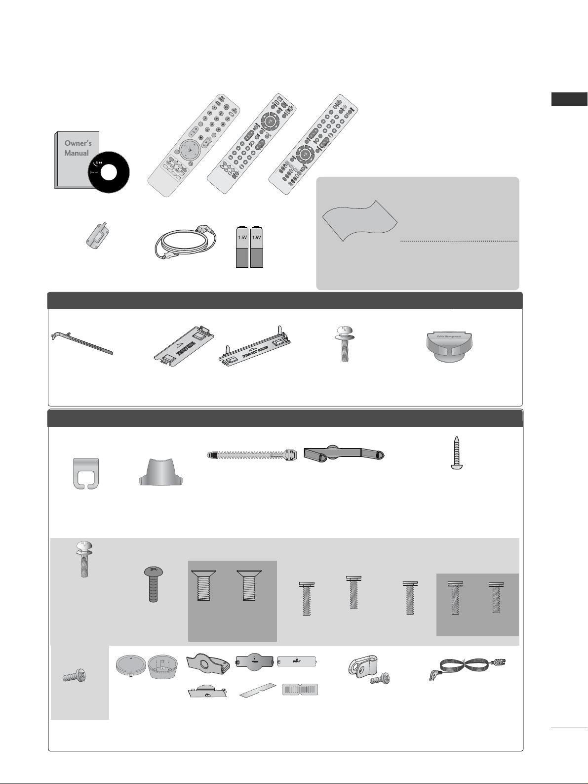
ACCESSORIES
ACCESSORIES
Ensure that the following accessories are included with your TV. If an accessory is missing, please contact
the dealer where you purchased the TV.
■
Image shown may differ from your TV.
Owner’s Manual
Batteries
Remote Control
Power Cord
Polishing Cloth
Polishing cloth for
use on the screen.
This item is not included for all models.
* Lightly wipe any stains or
fingerprints on the surface of the TV with the
polishing cloth.
Do not use excessive force.
This may cause scratching or
discolouration.
or
AV MODE
V MODE
ENERGY
ENERGY SA
SAVING
VING
RETURN / EXIT
MENU
Q.MENU INFO GUIDE
i
M
UTEMUTE
POWERPOWER
LIST
LIST
Q.VIEW
Q.VIEW
MARK
FAV
or
POWER
POWER
TV/RAD
TV/RAD
ON/OFF
ON/OFF
RA RATIO
AV MODEV MODE
MARK
MARK
FAV
Protection cover
(Refer to p.34)
PPLLAASSMMAA TTVV mmooddeellss
LLCCDD TTVV mmooddeellss // LLEEDD LLCCDD TTVV mmooddeellss
Cable management clip
(Only 32/37/42/47LH70**)
(Refer to p.33)
Stand rear cover
(Only 37/42/47LH70**)
(Refer to p.31)
Cable Holder
(Refer to p.33)
Bolts for stand assembly
(Only 50PS70**/50PS80**/
42/50PQ35**/42PQ65**/50PS65**)
(Refer to p.26)
x 4
x 2
Cable management clip
(Only 50/60PS70**,
50/60PS80**)
(Refer to p.33)
(Only 47LH70**)
x 7
Protection Cover
(Except for 19/22LU40**, 19/22/26LU50**)
(Refer to p.34)
or
or
Cable Holder
(Only 19/22LU40**,
19/22/26LU50**)
(Refer to p.32)
Cable management clip
(Only 19/22LH20
*
*,
19/22LD3
*
*,
19/22LG31**)
(Refer to p.32)
(Refer to p.30)
1-screw for stand fixing
(Only 26LG31**, 26LU50**, 32/37/42LF25**,
32/37/42LG2
***
, 32/37/42LG33**,
26/32/37/42LH20**, 26/32LD3**,
32/37/42LH3
***
, 32/37/42LH40**,
32/37/42LH49**, 32/37/42LH50**,
32/37LH70**, 42LH90
**
,
32/42LF51**)
x 8
Bolts for stand assembly
(Refer to p.
25 to28
)
(Only 32LH70**)
M4x20
M4x16
(Only 42LH70**)
x 3
M4x20
M4x16
x 4
(Only
19/22LU50**)
(Only
26LU50**)
x 2 x 3
or
Protective Bracket
and Bolt for Power Cord
(Only 32/37/42/47LH70
*
*
)
(Refer to p.33)
USB extension cable
(Only 32/37/42/47LH70
*
*
)
Make sure to use the provided
USB extension cable, Which is
specially designed for a slim fit.
x 8
M4x20
(Only 37LH70**)
Ferrite Core
(
This item is not included for
all models.
)
x 4
(Only 26LG31**,
32/37/42LF25**,
32/37/42LG2
***
,
32/37/42LG33
**
,
32/42LF51**)
x 4
(Only
19/22LU40**)
x 5
Stand Rear Body
Cap
(Only
19/22LU40**)
(Refer to p.28)
(Only 26LG31**,
32/37/42LF25**,
32/37/42LG2
***
,
32/37/42LG33**,
26/32/37/42LH20**,
26/32LD3**,
32/37/42/47LH3
***
,
32/37/42/47LH40**,
32/37/42/47LH49**,
32/37/42/47LH50**,
42/47LH90
**,
32/42LF51**)
CONTENTS
2
CONTENTS
ACCESSORIES
. . . . . . . . . . . . . . . . . . . . . . . . . . . . . . . . . . . . . . . . . . . .
1
PREPARATION
Front Panel Controls..................................................... 4
Back Panel Information .............................................. 16
Stand Installation ........................................................ 25
Detaching stand .......................................................29
Attaching the TV to a desk .....................................30
Desktop Pedestal Installation............................... 30
Positioning your display ........................................30
Kensington Security System .................................30
Careful installation advice ..................................... 31
Swivel Stand ..................................................................31
To use the stand rear cover ..................................................31
Back Cover for Wire Arrangement.......................... 32
Not Using the desk-type stand................................34
Wall Mount: Horizontal Installation........................ 35
Antenna Connection.................................................. 36
EXTERNAL EQUIPMENT SETUP
HD Receiver Setup...................................................... 37
DVD Setup .................................................................... 39
VCR Setup..................................................................... 42
Insertion of CI Module .............................................. 44
Digital Audio Out Setup ........................................... 45
Headphone Setup....................................................... 45
Other A/V Source Setup .......................................... 46
Usb Setup...................................................................... 47
PC Setup........................................................................ 48
- Screen Setup for PC Mode................................52
WATCHING TV / PROGRAMME CONTROL
Remote Control Key Functions ............................... 56
Turning on the TV....................................................... 62
Programme Selection ................................................ 62
Volume Adjustment ................................................... 62
Quick Menu ................................................................. 63
On-Screen Menus Selection and Adjustment..... 64
Auto Programme Tuning............................................ 65
Manual Programme Tuning (In Digital Mode)..... 68
Manual Programme Tuning (In Analogue Mode) ... 70
Programme Edit ........................................................... 72
Booster(In Digital Mode)...........................................74
Software Update.......................................................... 75
Diagnostics.................................................................... 76
CI Information.............................................................. 77
Selecting the Programme List .................................. 78
Favourite Programme Setup...................................... 79
Input List ....................................................................... 80
Data Service...............................................................81
Input Label .................................................................... 81
Simple Manual.............................................................. 82
................................................................. 83
AV Mode........................................................................ 86
Initializing (Reset to original factory settings) .....87
TO USE A BLUETOOTH
Precautions when using the Bluetooth................. 88
Setting the Bluetooth ................................................ 89
Set TV PIN .....................................................................90
Bluetooth headset
- Connecting a new Bluetooth headset..............91
- Connecting to Bluetooth headset already
registered.................................................................. 91
-
Disconnecting the Bluetooth headset during use
....92
- When requesting to connect to TV from the
Bluetooth headset....................................................92
Managing Registered Bluetooth device ................ 93
My Bluetooth Information. ........................................94
Receiving Photos from external Bluetooth device.........
95
Listening to the Musics from external Bluetooth device......
95
TO USE A USB DEVICE
When connecting a USB device.............................. 96
Photo List ...................................................................... 97
Music List......................................................................101
Movie List.....................................................................104
DivX Registration Code............................................108
Deactivation.................................................................109

CONTENTS
3
EPG (ELECTRONIC PROGRAMME
GUIDE) (IN DIGITAL MODE)
Switch on/off EPG..................................................... 110
Select a Programme................................................... 110
Button Function in NOW/NEXT Guide Mode...... 110
Button Function in 8 Day Guide Mode.................111
Button Function in Date Change Mode............... 111
Button Function in Extended Description Box .......
112
Button Function in Record/Remind Setting Mode
........ 112
Button Function in Schedule List Mode .............. 112
PICTURE CONTROL
Picture Size (Aspect Ratio) Control ..................... 113
Picture Wizard ..............................................................115
Energy Saving ...............................................................116
Preset Picture Settings
- Picture Mode-Preset .......................................... 117
Manual Picture Adjustment
- Picture Mode-User option................................ 118
Picture Improvement Technology.......................... 119
Expert Picture Control............................................. 120
Picture Reset............................................................... 123
LED Local dimming ..................................................123
Power Indicator............................................................124
Image Sticking Minimization (ISM) Method...... 125
Demo Mode................................................................ 126
Mode Setting ...............................................................127
SOUND & LANGUAGE CONTROL
Auto Volume Leveler................................................. 128
Clear Voice II................................................................129
Preset Sound Settings - Sound Mode .............. 130
Sound Setting Adjustment -User Mode ............131
SRS TruSurround XT............................................. 131
Balance .................................................................... 132
TV Speakers On/ Off Setup ................................132
DTV Audio setting (In Digital Mode only) . .133
Selecting Digital Audio Out.................................134
Audio Reset..............................................................135
Audio Description (In Digital Mode only)........136
I/II
- Stereo/Dual Reception (In Analogue Mode Only)
13 7
- NICAM Reception (In Analogue Mode Only) ... 138
- Speaker Sound Output Selection.................. 138
On-Screen Menu Language/Country Selection.... 139
Language Selection (In Digital Mode only)....... 140
TIME SETTING
Clock Setup................................................................. 141
Auto On/ Off Time Setting .................................... 142
Sleep Timer Setting .................................................. 143
PARENTAL CONTROL / RATINGS
Set Password & Lock System................................. 144
Block Programme....................................................... 145
Parental Control (In Digital Mode only)............. 146
External Input Blocking.............................................147
Key Lock ...................................................................... 148
TELETEXT
Switch on/off ............................................................. 149
SIMPLE Text................................................................ 149
TOP Text ...................................................................... 149
FASTEXT...................................................................... 150
Special Teletext Functions ...................................... 150
DIGITAL TELETEXT
Teletext within Digital Service ................................ 151
Teletext in Digital Service ........................................ 151
APPENDIX
Troubleshooting......................................................... 152
Maintenance .............................................................. 154
Product Specifications............................................. 155
IR Codes...................................................................... 169
External Control Device Setup .............................. 170

4
PREPARATION
PREPARATION
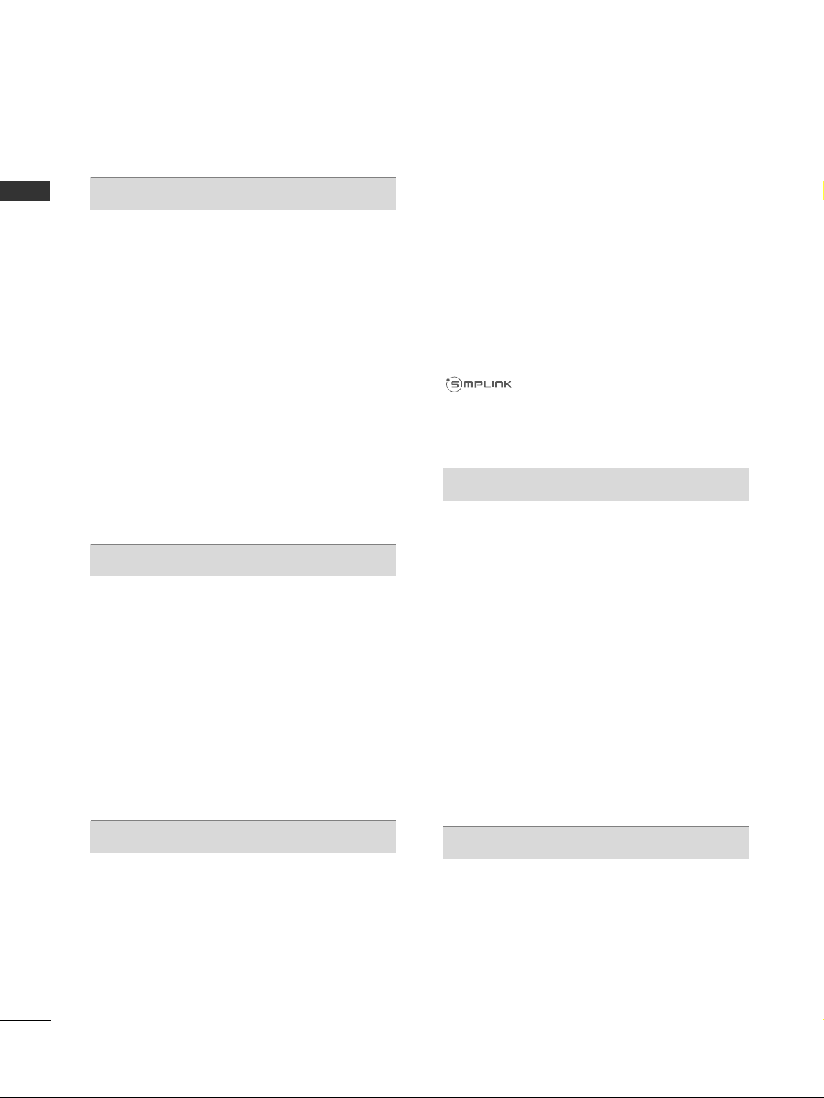
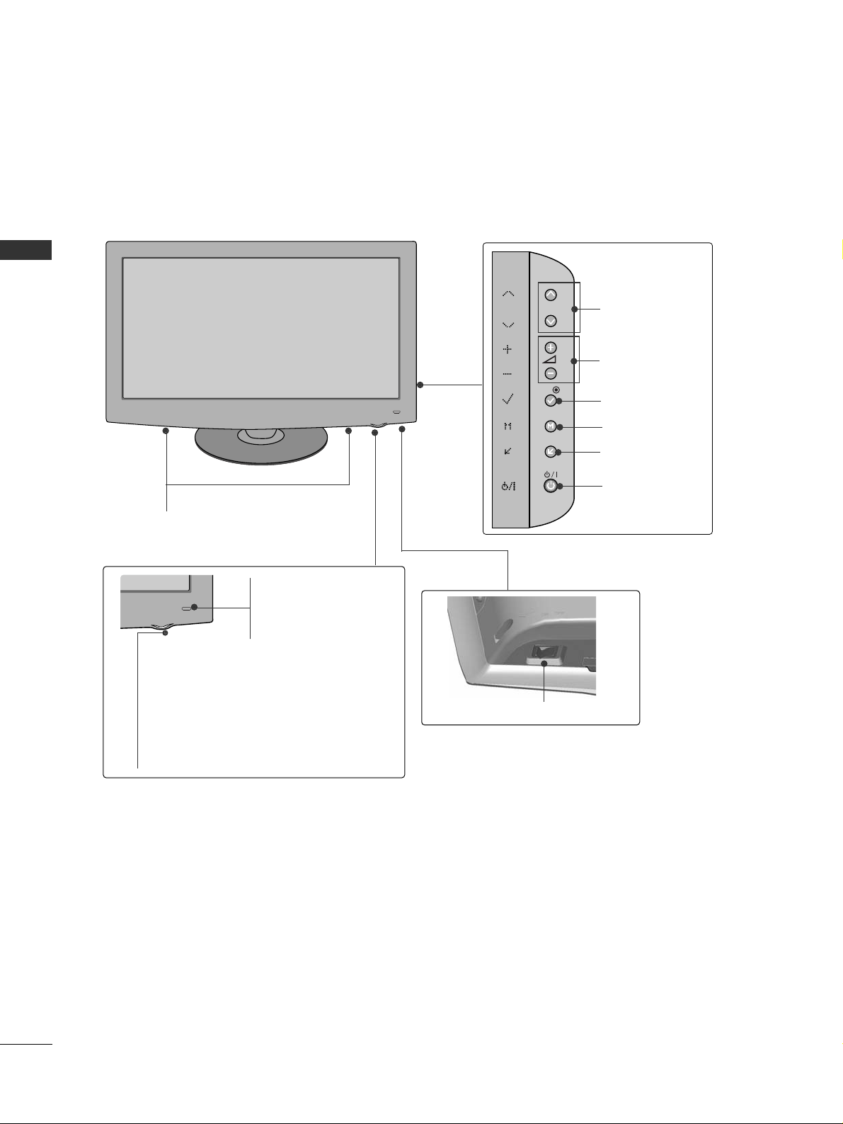
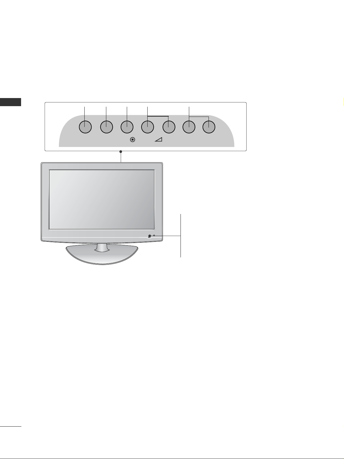
FRONT PANEL CONTROLS
■
Image shown may differ from your TV.
Plasma TV Models
PROGRAMME
VOLUME
OK
MENU
INPUT
POWER
G
When the TV cannot be turned on with the remote control, press the main power button on the TV.
(When the power is turned off with the main power button on the TV, it will not be turned on with the
remote control).
G
Do not step on the glass stand or subject it to any impact.
It may break, causing possible injury from fragments of glass, or the TV may fall.
G
Do not drag the TV. The floor or the product may be damaged.
CAUTION
Power/Standby Indicator
• Illuminates red in standby mode.
•
The LED is off while the TV remains on.
50/60PS70
**
IInn tt eell lliigg eenn tt SSee nnssoorr
Adjusts picture
according to the surrounding conditions.
RReemmoo ttee CC oonnttrrooll
SS eennssoo rr
NOTE
!
G
TV can be placed in standby mode in order to reduce the power consumption. And TV should be
switched off using the power switch on the TV if it will not be watched for some time, as this will
reduce energy consumption.
The energy consumed during use can be significantly reduced if the level of brightness of the picture is
reduced, and this will reduce the overall running cost.

5
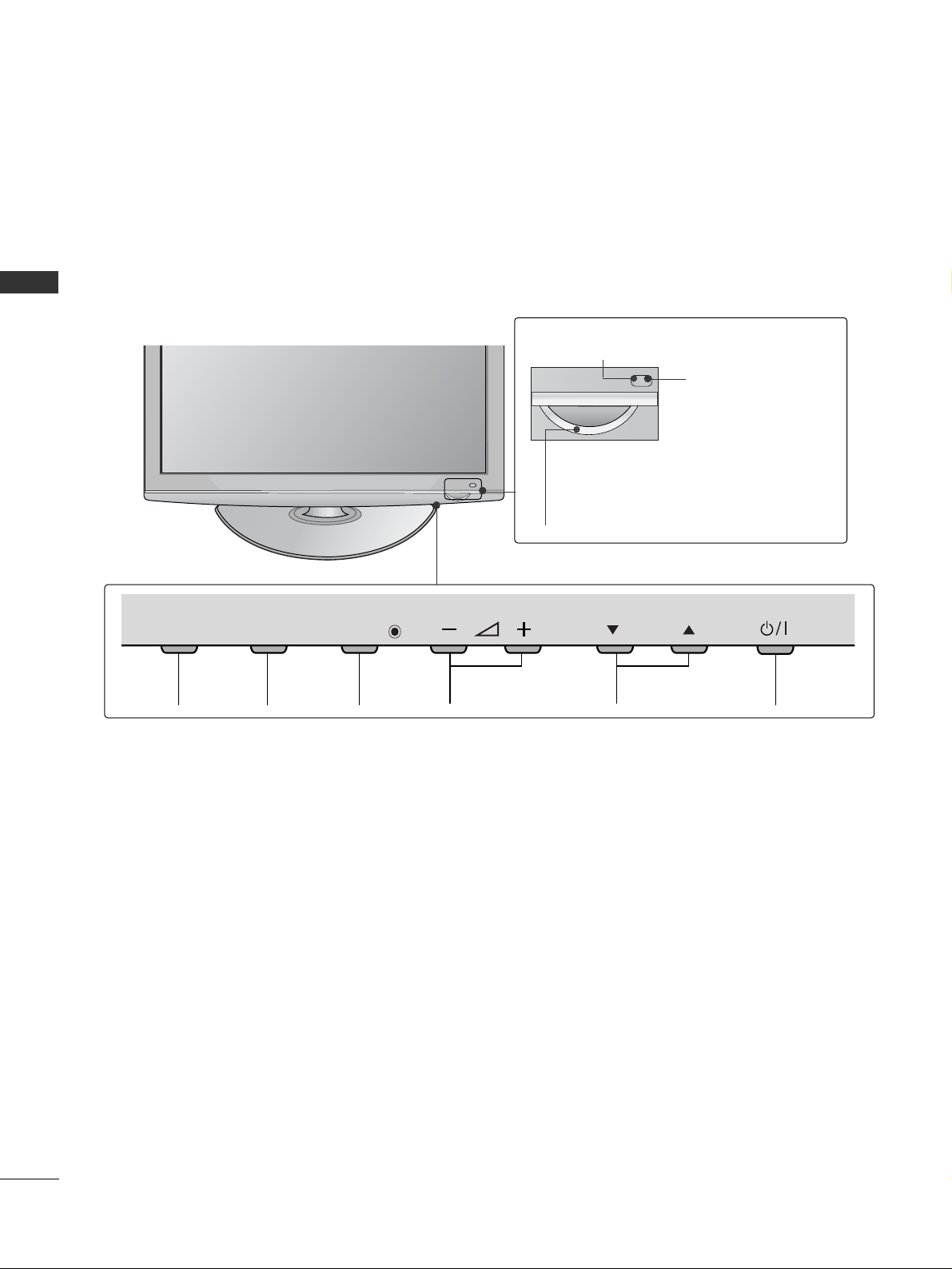
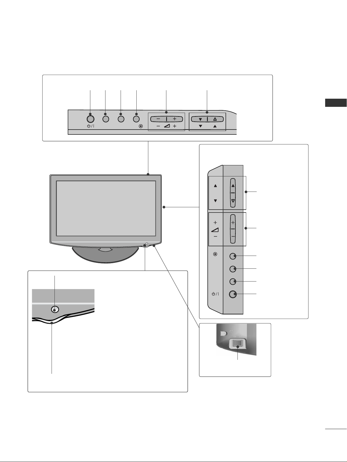
PREPARATION
PROGRAMME
VOLUME
OK
MENU
INPUT
POWER
Power/Standby Indicator
• Illuminates red in standby mode.
•
The LED is off while the TV remains on.
50/60PS80
**
IInn tt eell lliigg eenn tt SSee nnssoorr
Adjusts picture
according to the surrounding conditions.
RReemmoo ttee CC oonnttrrooll
SS eennssoo rr
6
PREPARATION
PREPARATION
PROGRAMMEVOLUMEMENU OKINPUT POWER
P
MENU
INPUTINPUT
OK
42/50PQ35
**
Intelligent Sensor
Adjusts picture according
to the surrounding
conditions.
Remote Control
Sensor
Power/Standby Indicator
•
Illuminates red in standby mode.
•
Illuminates blue when the TV is switched on.

7
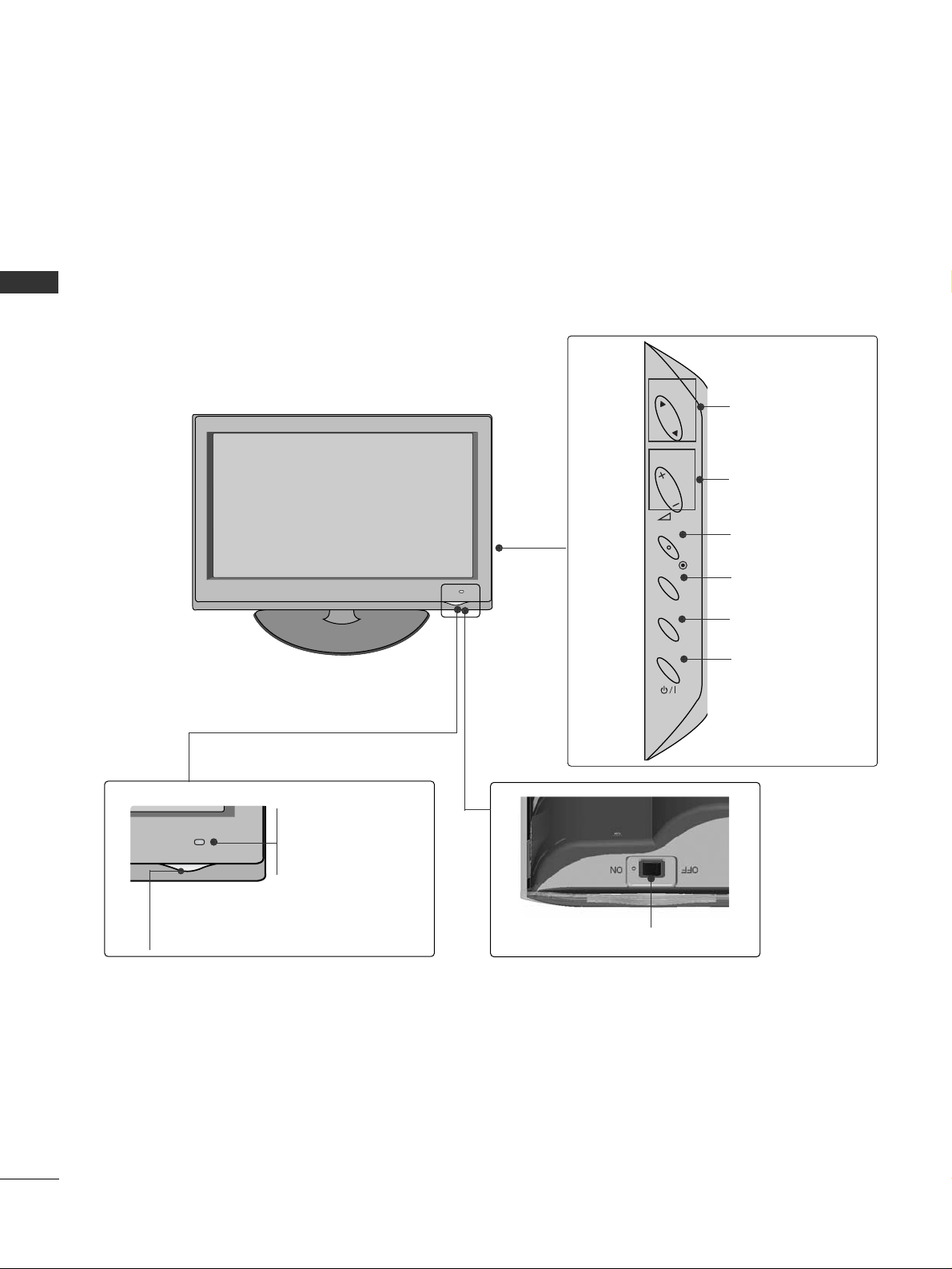
PREPARATION
42PQ65**, 50PS65
**
Power/Standby Indicator
• Illuminates red in standby mode.
• The LED is off while the TV remains on.
Remote Control
Sensor
Intelligent Sensor
Adjusts picture according to the surrounding
conditions
MENU
INPUT
OK
P
P
PROGRAMME
VOLUME
OK
MENU
INPUT
POWER
8
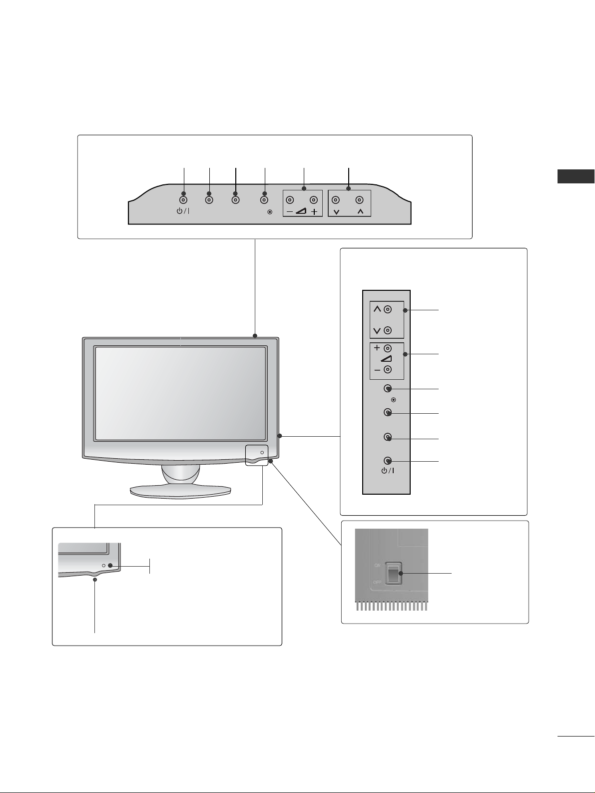
PREPARATION
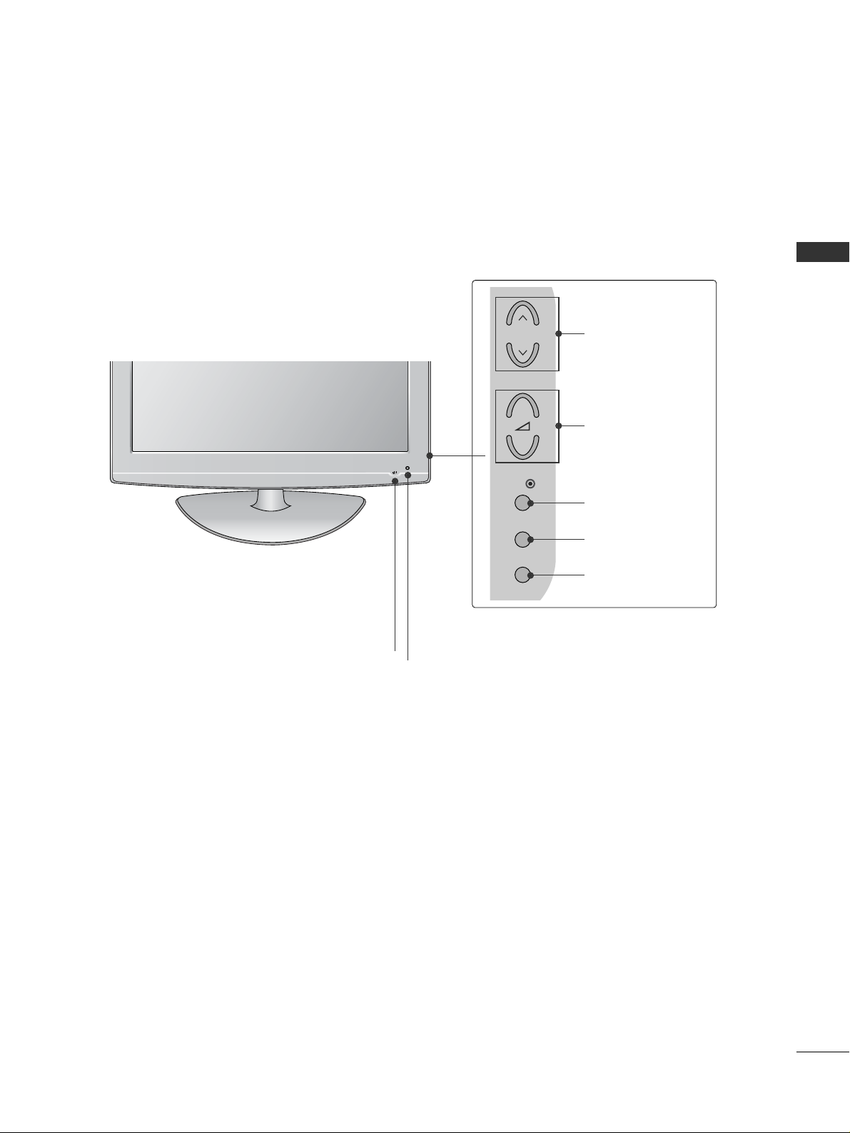
PREPARATION
INPUT
MENU
OK
P
PROGRAMME
VOLUME
OK
MENU
INPUT
POWER
Remote Control Sensor
Intelligent Sensor
Adjusts picture according to
the surrounding conditions.
Power/Standby Indicator
•
Illuminates red in standby mode.
•
Illuminates white when the TV is switched on.
Note: You can turn the
PP oo ww eerr IInn dd iicc aa ttoorr
on
or off in the OPTION menu.
SPEAKER
LED LCD TV Models : 42/47LH90
**
Main Power Switch

9
PREPARATION
LCD TV Models : 19/22LU40
**
Remote Control Sensor
Main
Power
Switch
INPUT
MENU
OK
P
PROGRAMME
VOLUME
OK
MENU
INPUT
POWER
Power/Standby
Indicator
• illuminates red in
standby mode.
•
The LED is off
while the TV
remains on.

10
PREPARATION
PREPARATION
LCD TV Models : 32/37/42/47LH70
**
P
P
OK
MENU
INPUT
P
PROGRAMME
VOLUME
OK
MENU
INPUT
Intelligent Sensor
Adjusts picture according to
the surrounding conditions
POWER(Touch Sensor)
Power/Standby Indicator
• Illuminates red in standby mode.
• Illuminates whitish when the TV is switched on.
Note: You can adjust
PP oo ww eerr IInn dd iicc aa ttoorr
in the
OPTION menu.
Moving LED
Remote Control Sensor
Main Power Switch
11
PREPARATION
(Only 32/37/42LH20**, 32LD3**,
32/37/42/47LH3
***
)
INPUT MENUPOK
PROGRAMME
VOLUME
(Only 19/22/26LH20**,
19/22/26LD3**)
INPUT
MENU
OK
P
PROGRAMME
VOLUME
OK
MENU
INPUT
POWER
OK
INPUT
POWER
MENU
Main Power Switch
Remote Control Sensor
Power/Standby Indicator
Illuminates red in standby mode.
Illuminates blue when the TV is switched on.
LCD TV Models : 19/22/26/32/37/42LH20**, 19/22/26/32LD3**,
32/37/42/47LH3
***
12
PREPARATION
PREPARATION
LCD TV Models : 32/37/42/47LH40**, 32/37/42/47LH49**,
32/37/42/47/55LH50
**
INPUT
MENU
OK
P
PROGRAMME
VOLUME
OK
MENU
INPUT
POWER
Remote Control Sensor
Intelligent Sensor
Adjusts picture according to
the surrounding conditions.
Power/Standby Indicator
• Illuminates red in standby mode.
• Illuminates blue when the TV is switched on.
Main Power Switch
13
PREPARATION
P
INPUT
MENU
OK
P
PROGRAMME
VOLUME
OK
MENU
INPUT
POWER
INPUT
MENU
OK
P
(Only 19/22LU50**)
(Only 26LU50**)
LCD TV Models : 19/22/26LU50
**
VOLUME
POWER
INPUT MENU OK
PROGRAMME
Main
Power
Switch
P
Remote Control Sensor
Power/Standby Indicator
Illuminates red in standby mode.
Illuminates white when the TV is switched on.
14
PREPARATION
PREPARATION
INPUT MENU P-+-+OK
PROGRAMMEVOLUME
MENU
OK
INPUT
LCD TV Models : 19/22LG31
**
POWER
Remote Control Sensor
Power/Standby Indicator
• illuminates red in standby mode.
• illuminates blue when the TV is switched on.
15
PREPARATION
LCD TV Models : 32/37/42LF25
**,
32/37/42LG2
***,
32/37/42LG33
**,
26LG31
**,
32/42/47LF51
**
POWER
Remote Control Sensor
Power/Standby Indicator
• illuminates red in standby mode.
• illuminates blue when the TV is switched on.
P
MENU
INPUT
OK
+
-
PROGRAMME
VOLUME
OK
MENU
INPUT
Intelligent Sensor
Adjusts picture according to the surrounding
conditions. (32/42/47LF51**only)
16
PREPARATION
PREPARATION
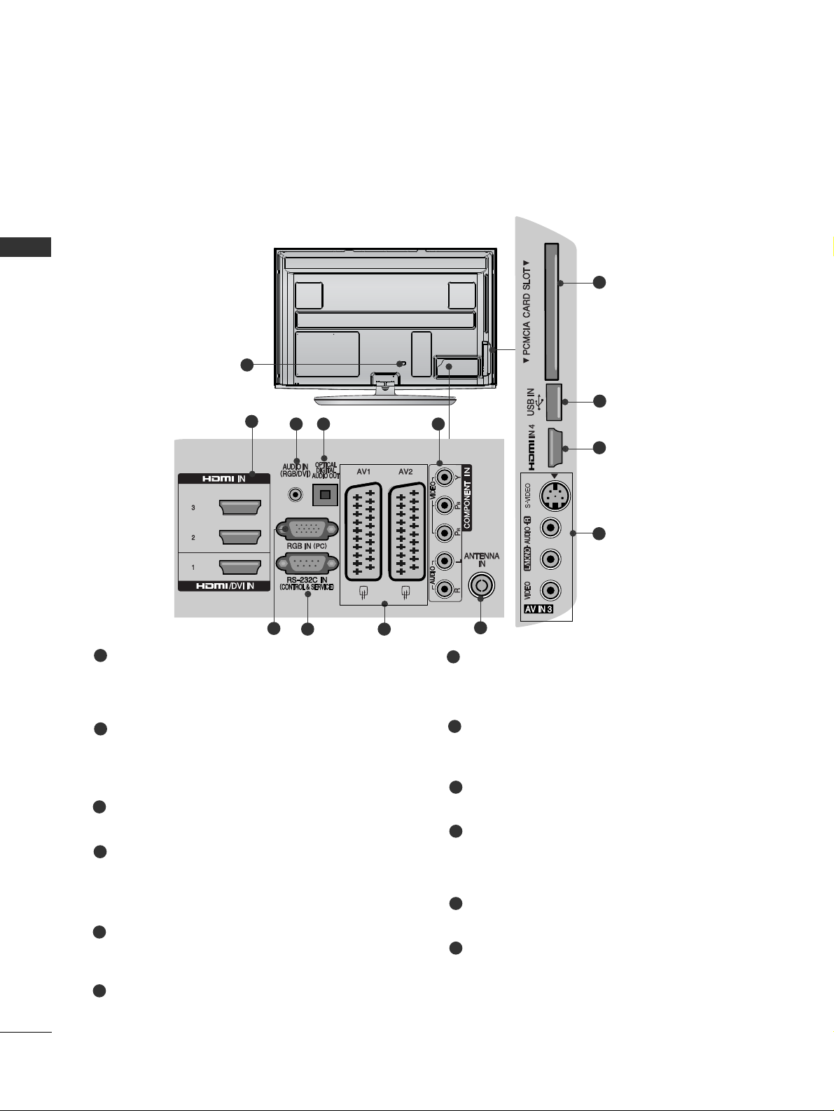
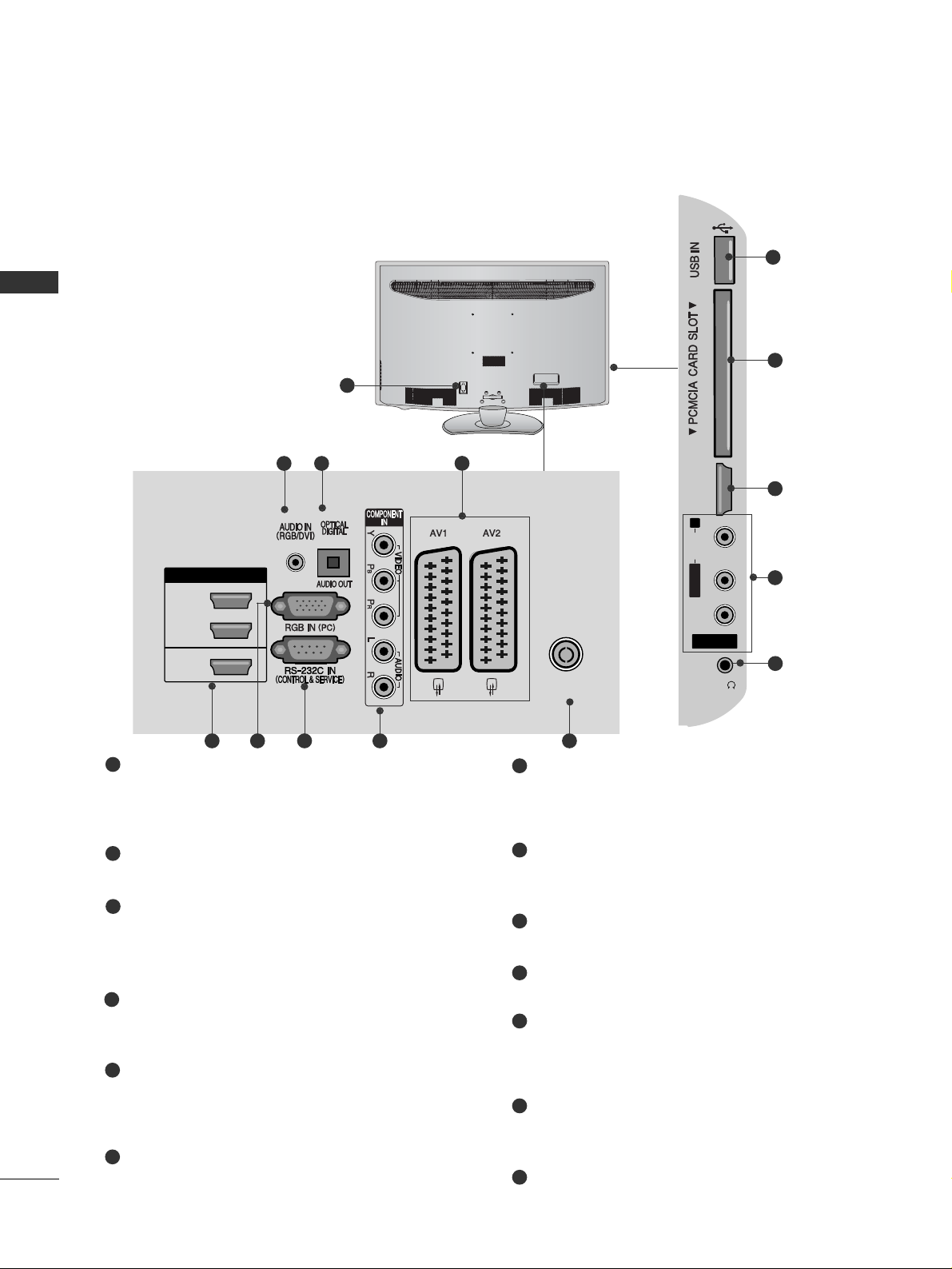
BACK PANEL INFORMATION
A
Image shown may differ from your TV.
Power Cord Socket
This TV operates on an AC power. The voltage is
indicated on the Specifications page.(
GG
p.155 to
16 7
) Never attempt to operate the TV on DC power.
HDMI/DVI IN Input
Connect an HDMI signal to HDMI IN.
Or DVI(VIDEO)signal to HDMI/DVI port with DVI
to HDMI cable.
RGB/DVI Audio Input
Connect the audio from a PC or DTV.
OPTICAL DIGITAL AUDIO OUT
Connect digital audio to various types of equipment.
Connect to a Digital Audio Component.
Use an Optical audio cable.
Component Input
Connect a component video/audio device to
these jacks.
RGB IN Input
Connect the output from a PC.
RS-232C IN (CONTROL & SERVICE) PORT
Connect to the RS-232C port on a PC.
This port is used for Service or Hotel mode.
Euro Scart Socket (AV1/AV2)
Connect scart socket input or output from an
external device to these jacks.
Antenna Input
Connect antenna or cable to this jack.
PCMCIA (Personal Computer Memory Card
International Association) Card Slot
Insert the CI Module to
PP CCMMCCII AA CC AARRDD SSLLOO TT ..
(This feature is not available in all countries.)
USB Input
Connect USB storage device to this jack.
S-Video Input
Connect S-Video out from an S-VIDEO device.
Audio/Video Input
Connect audio/video output from an external
device to these jacks.
1
2
3
4
7
8
9
10
11
12
1
5
6
2
3 4 5
6
7 8
9
Plasma TV Models : 50/60PS70**, 50/60PS80**
10
11
2
12

17
PREPARATION
Power Cord Socket
This TV operates on an AC power. The voltage is
indicated on the Specifications page. (
GG
p.155 to
16 7
) Never attempt to operate the TV on DC
power.
RGB/DVI Audio Input
Connect the audio from a PC or DTV.
OPTICAL DIGITAL AUDIO OUT
Connect digital audio to various types of equipment.
Connect to a Digital Audio Component.
Use an Optical audio cable.
Euro Scart Socket (AV1/AV2)
Connect scart socket input or output from an
external device to these jacks.
HDMI/DVI IN Input
Connect an HDMI signal to HDMI IN. Or DVI (VIDEO)
signal to HDMI/DVI port with DVI to HDMI cable.
RGB IN Input
Connect the output from a PC.
RS-232C IN (CONTROL & SERVICE) PORT
Connect to the RS-232C port on a PC.
This port is used for Service or Hotel mode.
Component Input
Connect a component video/audio device to
these jacks.
Antenna Input
Connect RF antenna to this jack.
PCMCIA (Personal Computer Memory Card
International Association) Card Slot
Insert the CI Module to
PP CCMMCCII AA CC AARRDD SSLLOO TT ..
(This feature is not available in all countries.)
USB Input
Connect USB storage device to this jack.
S-Video Input
Connect S-Video out from an S-VIDEO device.
Audio/Video Input
Connect audio/video output from an external
device to these jacks.
1
2
3
4
5
6
7
8
9
10
11
12
R
1
HDMI IN
HDMI/DVI IN
2
1
AV IN 3
L/ MONO
R
AUDIO
VIDEO
S-VIDEO HDMI IN 3
AV IN 3
L/MONO
R
AUDIOAUDIO
VIDEOVIDEO
S-VIDEO HDMI IN 3
USB IN
SERVICE ONLY
10
11
5
243
95 6 7 8
12
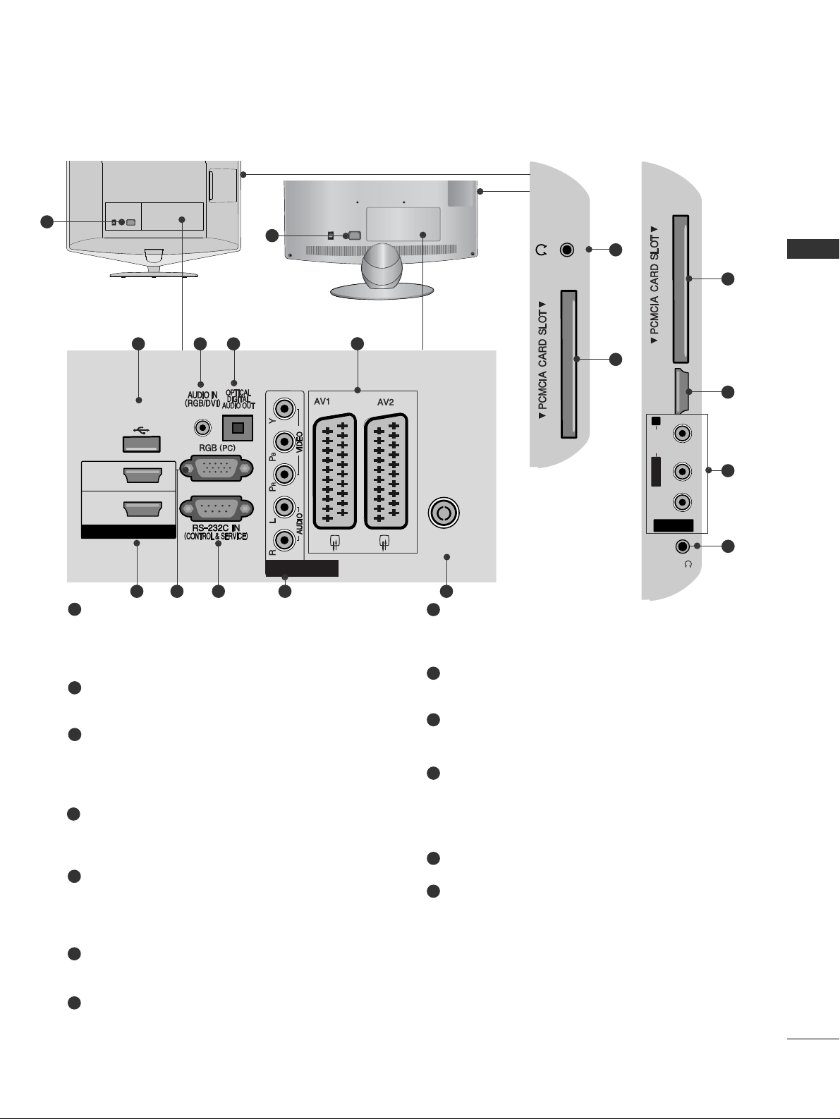
Plasma TV Models : 42/50PQ35
**,
42PQ65
**,
50PS65
**

18
PREPARATION
PREPARATION
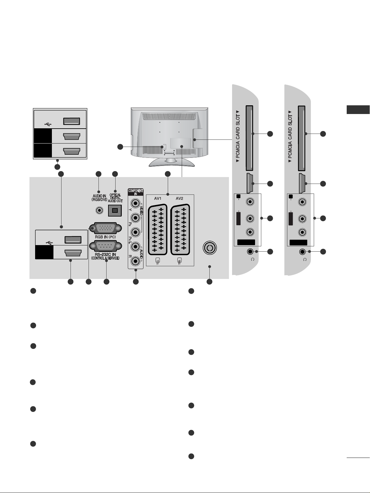
LCD TV Models : 32/37/42LF25**, 32/37/42LG2
***
, 32/37/42LG33**,
19/22/26LG31
**
Power Cord Socket
This TV operates on an AC power. The voltage is
indicated on the Specifications page.(
GG
p.155 to
16 7
) Never attempt to operate the TV on DC power.
RGB/DVI Audio Input
Connect the audio from a PC or DTV.
OPTICAL DIGITAL AUDIO OUT
Connect digital audio to various types of equipment.
Connect to a Digital Audio Component.
Use an Optical audio cable.
Euro Scart Socket (AV1/AV2)
Connect scart socket input or output from an
external device to these jacks.
HDMI/DVI IN Input
Connect an HDMI signal to HDMI IN. Or DVI
(VIDEO) signal to HDMI/DVI port with DVI to HDMI
cable.
RGB IN Input
Connect the output from a PC.
RS-232C IN (CONTROL & SERVICE) PORT
Connect to the RS-232C port on a PC.
This port is used for Service or Hotel mode.
Component Input
Connect a component video/audio device to
these jacks.
Antenna Input
Connect antenna or cable to this jack.
PCMCIA (Personal Computer Memory Card
International Association) Card Slot
Insert the CI Module to
PP CCMMCCII AA CC AARRDD SSLLOO TT ..
(This feature is not available in all countries.)
Audio/Video Input
Connect audio/video output from an external
device to these jacks.
Headphone Socket
Plug the headphone into the headphone socket.
SERVICE ONLY PORT
1
2
3
4
5
6
7
8
9
10
11
12
13
AV IN 3
L/MONO
R
AUDIOAUDIO
VIDEOVIDEO
HDMI
IN 2
H/P
10
5
11
12
AV IN 3
L/ MONO
R
AUDIO
VIDEO
HDMI
IN 2
1
ANTENNA IN
H/P
USB IN
SERVICE ONLY
HDMI
/ DVI IN
(RGB)
2
13
4
3
95 6 7 8
(Only 32/37/42LG2
***
,
32/37/42LG33**,
26LG 31**)
HDMI
IN 2
H/P
10
5
12
(Only 32/37/42LF25**)
1
H/P
12
10
(Only 19/22LG31**)
19
PREPARATION
LCD TV Models : 19/22LU40**, 19/22/26LU50
**
Power Cord Socket
This TV operates on an AC power. The voltage is
indicated on the Specifications page.(
GG
p.155 to
16 7
) Never attempt to operate the TV on DC power.
RGB/DVI Audio Input
Connect the audio from a PC or DTV.
OPTICAL DIGITAL AUDIO OUT
Connect digital audio to various types of equipment.
Connect to a Digital Audio Component.
Use an Optical audio cable.
Euro Scart Socket (AV1/AV2)
Connect scart socket input or output from an
external device to these jacks.
HDMI/DVI IN Input
Connect an HDMI signal to HDMI IN. Or DVI
(VIDEO) signal to HDMI/DVI port with DVI to HDMI
cable.
RGB Input
Connect the output from a PC.
RS-232C IN (CONTROL & SERVICE) PORT
Connect to the RS-232C port on a PC.
This port is used for Service or Hotel mode.
Component Input
Connect a component video/audio device to
these jacks.
Antenna Input
Connect antenna or cable to this jack.
Headphone Socket
Plug the headphone into the headphone socket.
PCMCIA (Personal Computer Memory Card
International Association) Card Slot
Insert the CI Module to
PP CCMMCCII AA CC AARRDD SSLLOO TT ..
(This feature is not available in all countries.)
SERVICE ONLY PORT
Audio/Video Input
Connect audio/video output from an external
device to these jacks.
1
2
3
4
5
6
7
8
9
10
11
12
13
H/P
R
AUDIO
HDMI
IN 3
11
10
H/P
AV IN 3
L/MONO
R
AUDIO
VIDEO
HDMI
IN 3
H/P
ON
OFF
1
ON
OFF
1
HDMI / DVI IN
2
1(DVI)
ANTENNA IN
COMPONENT IN
USB IN
SERVICE ONLY
H/P
AV IN 3
L/ MONO
R
AUDIO
VIDEO
HDMI
IN 3
H/P
(RGB)
ON
OFF
2
12
4
3
95 6 7 8
AV IN 3
L/MONO
R
AUDIOAUDIO
VIDEOVIDEO
HDMI
IN 3
H/P
11
5
13
10
(Only 26LU50**)
(Only 19/22LU40**)
(Only 19/22/26LU50**)

20
PREPARATION
PREPARATION
LCD TV Models : 32/37/42/47LH70
**
Power Cord Socket
This TV operates on an AC power. The voltage is
indicated on the Specifications page.(
GG
p.155 to
16 7
) Never attempt to operate the TV on DC power.
USB Input
Connect USB storage device to this jack.
HDMI/DVI IN Input
Connect an HDMI signal to HDMI IN.
Or DVI(VIDEO)signal to HDMI/DVI port with DVI
to HDMI cable.
S-Video Input
Connect S-Video out from an S-VIDEO device.
Audio/Video Input
Connect audio/video output from an external
device to these jacks.
RGB IN Input
Connect the output from a PC.
RGB/DVI Audio Input
Connect the audio from a PC or DTV.
RS-232C IN (CONTROL & SERVICE) PORT
Connect to the RS-232C port on a PC.
This port is used for Service or Hotel mode.
Antenna Input
Connect antenna or cable to this jack.
Component Input
Connect a component video/audio device to
these jacks.
OPTICAL DIGITAL AUDIO OUT
Connect digital audio to various types of equipment.
Connect to a Digital Audio Component.
Use an Optical audio cable.
Euro Scart Socket (AV1/AV2)
Connect scart socket input or output from an
external device to these jacks.
Headphone Socket
Plug the headphone into the headphone socket.
PCMCIA (Personal Computer Memory Card
International Association) Card Slot
Insert the CI Module to
PP CCMMCCII AA CC AARRDD SSLLOO TT ..
(This feature is not available in all countries.)
1
2
3
4
7
8
9
10
11
12
5
6
(RGB)
1
5 764
10 118 9
12
2
3

21
PREPARATION
LCD TV Models : 32/37/42/47LH40**, 32/37/42/47LH49**,
32/37/42/47/
55LH50
**
,
32/42/47LF51
**
Power Cord Socket
This TV operates on an AC power. The voltage is
indicated on the Specifications page.(
GG
p.155 to
16 7
) Never attempt to operate the TV on DC power.
RGB/DVI Audio Input
Connect the audio from a PC or DTV.
OPTICAL DIGITAL AUDIO OUT
Connect digital audio to various types of equipment.
Connect to a Digital Audio Component.
Use an Optical audio cable.
Euro Scart Socket (AV1/AV2)
Connect scart socket input or output from an
external device to these jacks.
HDMI/DVI IN Input
Connect an HDMI signal to HDMI IN. Or DVI
(VIDEO) signal to HDMI/DVI port with DVI to HDMI
cable.
RGB IN Input
Connect the output from a PC.
RS-232C IN (CONTROL & SERVICE) PORT
Connect to the RS-232C port on a PC.
This port is used for Service or Hotel mode.
Component Input
Connect a component video/audio device to
these jacks.
Antenna Input
Connect antenna or cable to this jack.
USB Input
Connect USB storage device to this jack.
PCMCIA (Personal Computer Memory Card
International Association) Card Slot
Insert the CI Module to
PP CCMMCCII AA CC AARRDD SSLLOO TT ..
(This feature is not available in all countries.)
Audio/Video Input
Connect audio/video output from an external
device to these jacks.
Headphone Socket
Plug the headphone into the headphone socket.
SERVICE ONLY PORT
1
2
3
4
5
6
8
7
9
10
11
12
13
14
AV IN 3AV IN 3
L/L/MONOMONO
R
AUDIOAUDIO
VIDEOVIDEO
HDMI HDMI
IN 3IN 3
H/PH/P
AV IN 3
L/MONO
R
AUDIO
VIDEO
HDMI
IN 3
H/P
11
10
5
12
13
AV IN 3AV IN 3
L/L/MONOMONO
R
AUDIOAUDIO
VIDEOVIDEO
HDMI HDMI
IN 3IN 3
H/PH/P
USB IN
SERVICE ONLY
11
14
5
12
13
AV IN 3
L/MONO
R
AUDIOAUDIO
VIDEOVIDEO
HDMI
IN 4
H/P
11
10
5
12
13
1
AV IN 3
L/MONO
R
AUDIO
VIDEO
HDMI
IN 3
HDMI / DVI IN
2
1(DVI)
ANTENNA IN
H/P
AV IN 3
L/MONO
R
AUDIO
VIDEO
HDMI
IN 3
H/P
(RGB)
243
95 6 7 8
HDMI / DVI IN
2
3
1(DVI)
AV IN 3
L/ MONO
R
AUDIO
VIDEO
HDMI
IN 4
H/P
(Only 32/37/42/47/55LH50**,
32/37/42/47LH49**)
5
(Only 32/37/42/47/55LH50**,
32/37/42/47LH49**)
1
(Only 32/42/47LF51**)
(Only 32/42/47LF51**)
(Only
32/37/42/47LH40**)
22
PREPARATION
PREPARATION
LED LCD TV Models : 42/47LH90
**
Power Cord Socket
This TV operates on an AC power. The voltage is
indicated on the Specifications page.(
GG
p.155 to
16 7
) Never attempt to operate the TV on DC power.
RGB/DVI Audio Input
Connect the audio from a PC or DTV.
OPTICAL DIGITAL AUDIO OUT
Connect digital audio to various types of equipment.
Connect to a Digital Audio Component.
Use an Optical audio cable.
Euro Scart Socket (AV1/AV2)
Connect scart socket input or output from an
external device to these jacks.
HDMI/DVI IN Input
Connect an HDMI signal to HDMI IN. Or DVI
(VIDEO) signal to HDMI/DVI port with DVI to HDMI
cable.
RGB IN Input
Connect the output from a PC.
RS-232C IN (CONTROL & SERVICE) PORT
Connect to the RS-232C port on a PC.
This port is used for Service or Hotel mode.
Component Input
Connect a component video/audio device to
these jacks.
Antenna Input
Connect antenna or cable to this jack.
USB Input
Connect USB storage device to this jack.
PCMCIA (Personal Computer Memory Card
International Association) Card Slot
Insert the CI Module to
PP CCMMCCII AA CC AARRDD SSLLOO TT ..
(This feature is not available in all countries.)
Audio/Video Input
Connect audio/video output from an external
device to these jacks.
Headphone Socket
Plug the headphone into the headphone socket.
1
2
3
4
5
6
8
7
9
10
11
12
13
AV IN 3
L/MONO
R
AUDIOAUDIO
VIDEOVIDEO
HDMI
IN 4
H/P
11
10
5
12
13
1
HDMI / DVI IN
2
3
1(DVI)
ANTENNA IN
AV IN 3
L/ MONO
R
AUDIO
VIDEO
HDMI
IN 4
H/P
(RGB)
243
95 6 7 8
23
PREPARATION
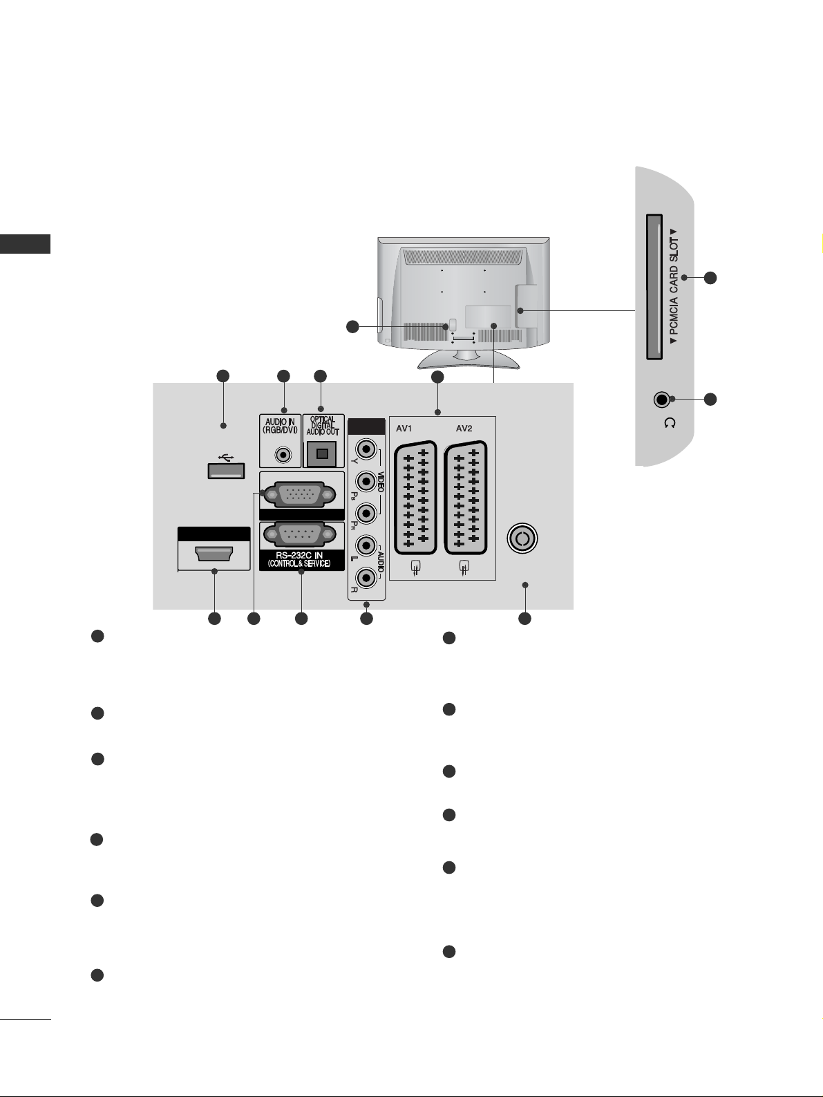
LCD TV Models : 26/32/37/42LH20**, 26/32LD3**, 32/37/42/47LH3
***
Power Cord Socket
This TV operates on an AC power. The voltage is
indicated on the Specifications page.(
GG
p.155 to
16 7
) Never attempt to operate the TV on DC power.
RGB/DVI Audio Input
Connect the audio from a PC or DTV.
OPTICAL DIGITAL AUDIO OUT
Connect digital audio to various types of equipment.
Connect to a Digital Audio Component.
Use an Optical audio cable.
Euro Scart Socket (AV1/AV2)
Connect scart socket input or output from an
external device to these jacks.
HDMI/DVI IN Input
Connect an HDMI signal to HDMI IN. Or DVI
(VIDEO) signal to HDMI/DVI port with DVI to HDMI
cable.
RGB IN Input
Connect the output from a PC.
RS-232C IN (CONTROL & SERVICE) PORT
Connect to the RS-232C port on a PC.
This port is used for Service or Hotel mode.
Component Input
Connect a component video/audio device to
these jacks.
Antenna Input
Connect antenna or cable to this jack.
PCMCIA (Personal Computer Memory Card
International Association) Card Slot
Insert the CI Module to
PP CCMMCCII AA CC AARRDD SSLLOO TT ..
(This feature is not available in all countries.)
Audio/Video Input
Connect audio/video output from an external
device to these jacks.
Headphone Socket
Plug the headphone into the headphone socket.
SERVICE ONLY PORT
1
2
3
4
5
6
7
8
9
10
11
12
13
AV IN 3
L/MONO
R
AUDIOAUDIO
VIDEOVIDEO
HDMI
IN 3
H/P
10
5
11
12
AV IN 3
L/MONO
R
AUDIOAUDIO
VIDEOVIDEO
HDMI
IN 2
H/P
10
5
11
12
1
AV IN 3
L/ MONO
R
AUDIO
VIDEO
HDMI
IN 2
1
ANTENNA IN
H/P
USB IN
SERVICE ONLY
HDMI
/ DVI IN
(RGB)
2
13
4
3
95 6 7 8
AV IN 3
L/ MONO
R
AUDIO
VIDEO
HDMI
IN 3
2
1
H/P
USB IN
SERVICE ONLY
HDMI
/ DVI IN
HDMI
(Only 32/37/42/47LH3
***
)
5
(Only 32/37/42/47LH3
***
)
(Only 26/32/37/42LH20**,
26/32LD3**)
24
PREPARATION
PREPARATION
LCD TV Models : 19/22LH20**, 19/22LD3
**
Power Cord Socket
This TV operates on an AC power. The voltage is
indicated on the Specifications page.(
GG
p.155 to
16 7
) Never attempt to operate the TV on DC power.
RGB/DVI Audio Input
Connect the audio from a PC or DTV.
OPTICAL DIGITAL AUDIO OUT
Connect digital audio to various types of equipment.
Connect to a Digital Audio Component.
Use an Optical audio cable.
Euro Scart Socket (AV1/AV2)
Connect scart socket input or output from an
external device to these jacks.
HDMI/DVI IN Input
Connect an HDMI signal to HDMI IN. Or DVI
(VIDEO) signal to HDMI/DVI port with DVI to HDMI
cable.
RGB IN Input
Connect the output from a PC.
RS-232C IN (CONTROL & SERVICE) PORT
Connect to the RS-232C port on a PC.
This port is used for Service or Hotel mode.
Component Input
Connect a component video/audio device to
these jacks.
Antenna Input
Connect antenna or cable to this jack.
Headphone Socket
Plug the headphone into the headphone socket.
PCMCIA (Personal Computer Memory Card
International Association) Card Slot
Insert the CI Module to
PP CCMMCCII AA CC AARRDD SSLLOO TT ..
(This feature is not available in all countries.)
SERVICE ONLY PORT
1
2
3
4
5
6
7
8
9
10
11
12
H/P
10
11
1
HDMI / DVI IN
ANTENNA IN
COMPONENT IN
USB IN
SERVICE ONLY
H/P
RGB IN (PC)
(RGB)
2
12
4
3
95 6 7 8
25
PREPARATION
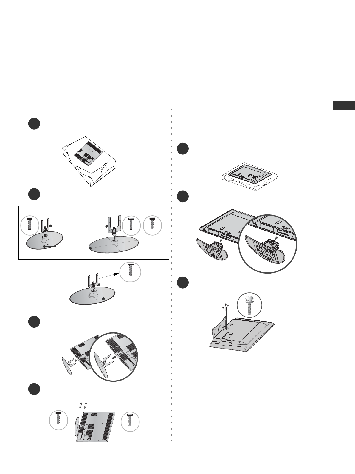
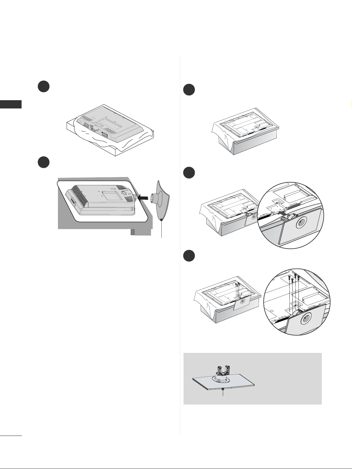
STAND INSTALLATION
1
3
4
Carefully place the TV screen side down on a cushioned surface to protect the screen from damage.
2
Assemble the parts of the
SSttaa nndd BBooddyy
with
the
SSttaa nndd BBaassee
of the TV.
Assemble the TV as shown.
Fix the 4 bolts securely using the holes in the
back of the TV.
32LH70
**
Stand Body
Stand Base
42LH70
**
Only 32/37/42/47LH70
**
47 LH 70**37LH70
**
Stand Body
Stand Base
32/37LH70
**
M4x20
M4x20
M4x16
M4x20
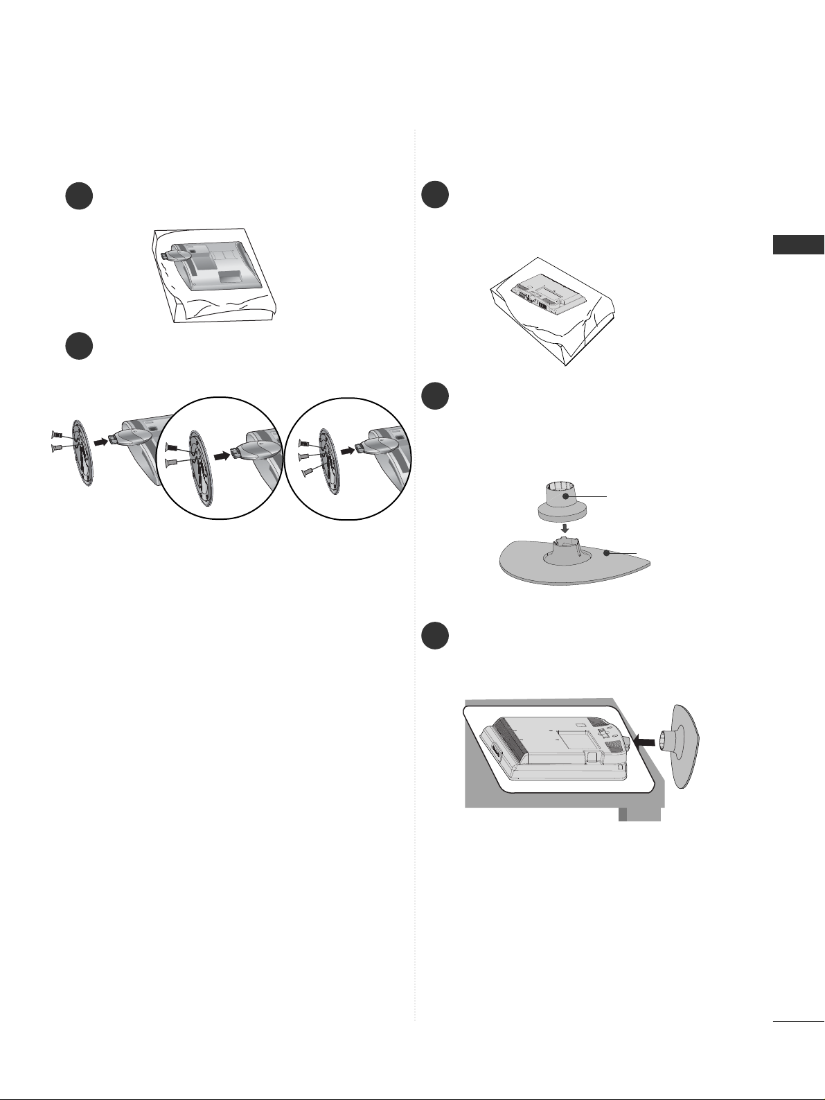
1
2
3
Carefully place the TV screen side down on a cushioned
surface to protect the screen from damage.
Assemble the TV as shown.
Fix the 4 bolts securely using the holes in the
back of the TV.
Only 26/32/37/42LH20**, 26/32LD3**,
32/37/42/47LH3
***
, 32/37/42/47LH40**,
32/37/42/47LH49**, 32/37/42/47LH50**,
42/47LH90
**
M4x20
42/47LH70
**
M4x16
■
Image shown may differ from your TV
When assembling the desk type stand, check whether the bolt is fully tightened. (If not tightened fully, the product can
tilt forward after the product installation.) If you tighten the bolt with excessive force, the bolt can deviate from abrasion
of the tightening part of the bolt.
26
PREPARATION
PREPARATION
Only 50PS70**/50PS80**/
42/50PQ35**/42PQ65**/50PS65
**
1
2
3
Carefully place the TV screen side down on a cushioned
surface to protect the screen from damage.
Assemble the TV as shown.
Fix the 4 bolts securely using the holes in the
back of the TV.
When assembling the
stand, make sure to
distinguish and
assemble the front
and rear side of the
stand correctly.
Front
1
Carefully place the TV screen side down on a cushioned surface to protect the screen from damage.
2
Assemble the TV as shown.
Only 19/22LH20**, 19/22LD3
**
Cover Base
27
PREPARATION
1
2
Carefully place the TV screen side down on a cushioned surface to protect the screen from damage.
Fix the 2 or 3 bolts securely using the holes.
Only 19/22/26LU50
**
(Only 26LU50**)
Only 19/22LG31
**
Stand Body
Cover Base
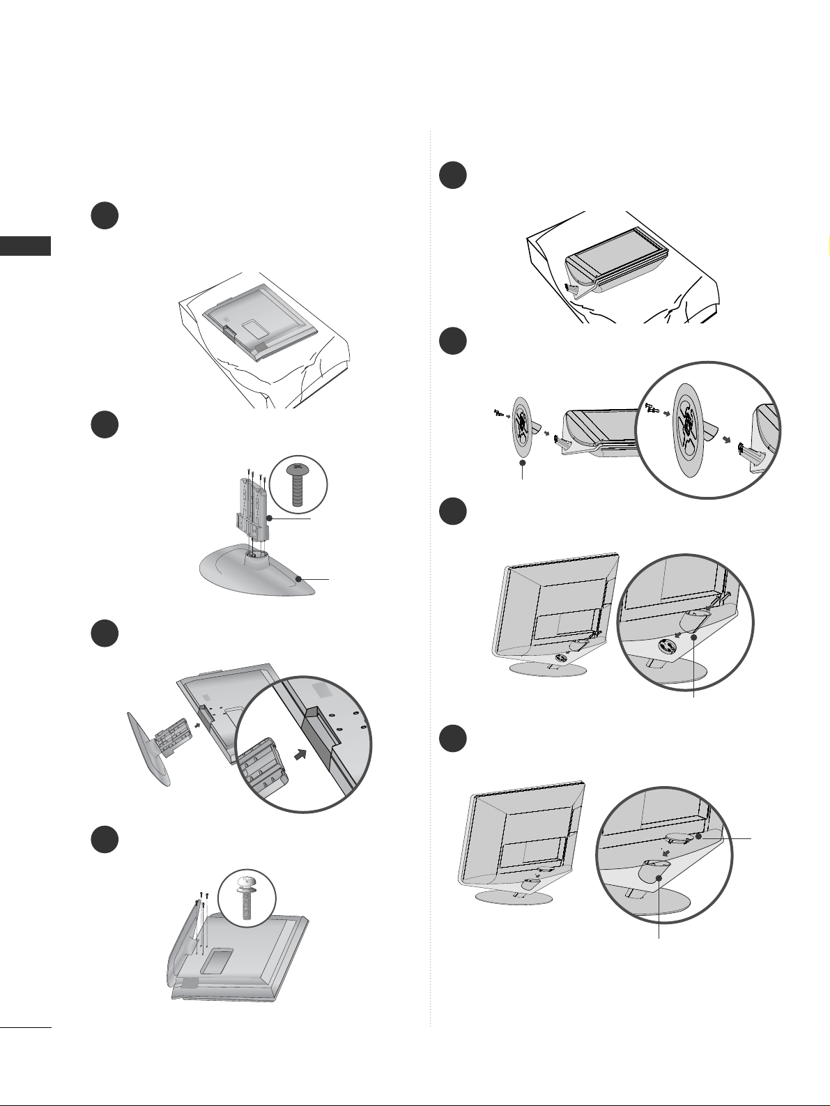
1
2
3
Carefully place the TV screen side down on a
cushioned surface to protect the screen from
damage.
Assemble the parts of the
SSttaanndd BB ooddyy
with
CCoovveerr BB aassee
of the TV. Insert the
SSttaanndd
BBoo ddyy
into a
CCoovveerr BB aassee
until clicking sound.
Assemble the TV as shown.
28
PREPARATION
PREPARATION
1
3
4
Carefully place the TV screen side down on a
cushioned surface to protect the screen from
damage.
2
Assemble the parts of the
SSttaa nndd BBooddyy
with
the
CCoo vvee rr BB aass ee
of the TV.
Assemble the TV as shown.
Fix the 4 bolts securely using the holes in the
back of the TV.
Stand Body
Cover Base
Only 32/37/42LF25
**,
32/37/42LG2
***,
32/37/42LG33
**,
26LG31
**,
32/42LF51
**
1
3
4
Carefully place the TV screen side down on a cushioned surface to protect the screen from damage.
2
Fix the 3 bolts securely using the holes in the
CCoo vvee rr BB aass ee
.
Assemble the parts of the
SSttaanndd RReeaa rr BB oodd yy
with the TV.
Assemble the parts of the
CC aapp
with the
SSttaa nn dd
RReeaarr BBoodd yy
of the TV.
Only 19/22LU40
**
Stand Rear Body
Cover Base
Stand Rear Body
Cap
 Loading...