

Page 1

PLASMA TV
SERVICE MANUAL
CAUTION
BEFORE SERVICING THE CHASSIS,
READ THE SAFETY PRECAUTIONS IN THIS MANUAL.
CHASSIS : PP91B
MODEL : 42PQ301R 42PQ301R-ZB
North/Latin America http://aic.lgservice.com
Europe/Africa http://eic.lgservice.com
Asia/Oceania http://biz.lgservice.com
Internal Use Only
P/NO : MFL60273009 (0906-REV00) Printed in Korea
Page 2

- 2 -
LGE Internal Use OnlyCopyright ©2009 LG Electronics. Inc. All right reserved.
Only for training and service purposes
CONTENTS
CONTENTS ............................................................................................................................... 2
SAFETY PRECAUTIONS ...........................................................................................................3
SPECIFICATION.........................................................................................................................4
ADJUSTMENT INSTRUCTION ..................................................................................................8
BLOCK DIAGRAM ...................................................................................................................16
EXPLODED VIEW ..................................................................................................................17
SVC. SHEET ................................................................................................................................
Page 3
- 3 -
LGE Internal Use OnlyCopyright ©2009 LG Electronics. Inc. All right reserved.
Only for training and service purposes
SAFETY PRECAUTIONS
Many electrical and mechanical parts in this chassis have special safety-related characteristics. These parts are identified by in the
Schematic Diagram and Exploded View.
It is essential that these special safety parts should be replaced with the same components as recommended in this manual to prevent
X-RADIATION, Shock, Fire, or other Hazards.
Do not modify the original design without permission of manufacturer.
General Guidance
An isolation Transformer should always be used during the
servicing of a receiver whose chassis is not isolated from the AC
power line. Use a transformer of adequate power rating as this
protects the technician from accidents resulting in personal injury
from electrical shocks.
It will also protect the receiver and it's components from being
damaged by accidental shorts of the circuitry that may be
inadvertently introduced during the service operation.
If any fuse (or Fusible Resistor) in this monitor is blown, replace it
with the specified.
When replacing a high wattage resistor (Oxide Metal Film Resistor,
over 1W), keep the resistor 10mm away from PCB.
Keep wires away from high voltage or high temperature parts.
Due to high vacuum and large surface area of picture tube,
extreme care should be used in handling the Picture Tube.
Do not lift the Picture tube by it's Neck.
Leakage Current Cold Check(Antenna Cold Check)
With the instrument AC plug removed from AC source, connect an
electrical jumper across the two AC plug prongs. Place the AC
switch in the on position, connect one lead of ohm-meter to the AC
plug prongs tied together and touch other ohm-meter lead in turn to
each exposed metallic parts such as antenna terminals, phone
jacks, etc.
If the exposed metallic part has a return path to the chassis, the
measured resistance should be between 1MΩ and 5.2MΩ.
When the exposed metal has no return path to the chassis the
reading must be infinite.
An other abnormality exists that must be corrected before the
receiver is returned to the customer.
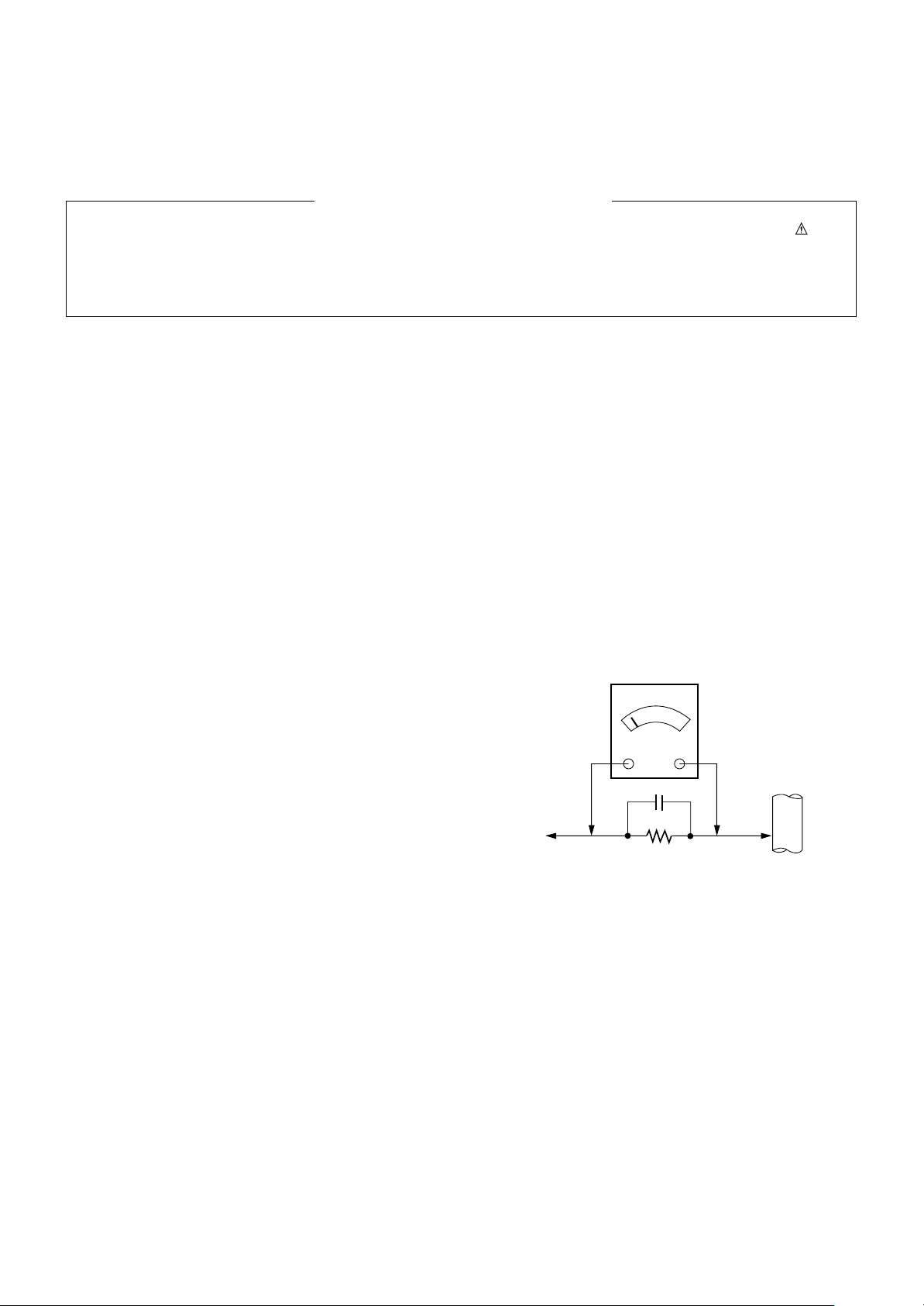
Leakage Current Hot Check (See below Figure)
Plug the AC cord directly into the AC outlet.
Do not use a line Isolation Transformer during this check.
Connect 1.5K/10watt resistor in parallel with a 0.15uF capacitor
between a known good earth ground (Water Pipe, Conduit, etc.)
and the exposed metallic parts.
Measure the AC voltage across the resistor using AC voltmeter
with 1000 ohms/volt or more sensitivity.
Reverse plug the AC cord into the AC outlet and repeat AC voltage
measurements for each exposed metallic part. Any voltage
measured must not exceed 0.75 volt RMS which is corresponds to
0.5mA.
In case any measurement is out of the limits specified, there is
possibility of shock hazard and the set must be checked and
repaired before it is returned to the customer.
Leakage Current Hot Check circuit
1.5 Kohm/10W
To Instrument's
exposed
METALLIC PARTS
Good Earth Ground
such as WATER PIPE,
CONDUIT etc.
AC Volt-meter
IMPORTANT SAFETY NOTICE
0.15uF
Page 4

- 4 -
LGE Internal Use OnlyCopyright ©2009 LG Electronics. Inc. All right reserved.
Only for training and service purposes
SPECIFICATIONS
NOTE : Specifications and others are subject to change without notice for improvement
.
V Application Range
This spec is applied to PDP TV used PP91A/B/C/D Chassis.
V Specification
Each part is tested as below without special appointment.
1) Temperature : 25±5°C (77±9°F), CST : 40±5
2) Relative Humidity: 65±10%
3) Power Voltage: Standard Input voltage (100-240V~, 50/60Hz)
* Standard Voltage of each product is marked by models.
4) Specification and performance of each parts are followed each drawing and specification by part number in accordance with SBOM.
5) The receiver must be operated for about 20 minutes prior to the adjustment.
V Test Method
1) Performance : LGE TV test method followed.
2) Demanded other specification
Safety : CE, IEC specification
EMC : CE, IEC
Remark
Safety: IEC/EN60065, EMI: EN55013,
EMS: EN55020
Safety: IEC/EN60065, EMI: CISPR13
Market
EU
NON-EU
Central and South America
Appliance
TEST
TEST
Page 5
- 5 -
LGE Internal Use OnlyCopyright ©2009 LG Electronics. Inc. All right reserved.
Only for training and service purposes
V Module Specification
(1) 42” XGA
(2) 50” WXGA
(3) 50” FHD
Display Screen Device
Aspect Ratio
PDP Module
Operating Environment
Storage Environment
Input Voltage
1
2
3
4
5
6
No Item Specification Remark
50 inch 16:9 Color plasma Display Module
16:9
PDP50G2####,
RGB Closed(Well) Type
1) Temp. : 0 ~ 55deg
2) Humidity : 20 ~ 80%
3) Temp. : -10 ~ 60deg
4) Humidity : 10 ~ 90%
AC100-240V~, 50/60Hz
PDP
Glass Filter
LGE SPEC.
Maker: LGIT
Display Screen Device
Aspect Ratio
PDP Module
Operating Environment
Storage Environment
Input Voltage
1
2
3
4
5
6
No Item Specification Remark
50 inch 16:9 Color plasma Display Module
16:9
PDP50H3####,
RGB Closed Type
1) Temp. : 0 ~ 55deg
2) Humidity : 20 ~ 80%
3) Temp. : -10 ~ 60deg
4) Humidity : 10 ~ 90%
AC100-240V~, 50/60Hz
PDP
Glass Filter
LGE SPEC.
Maker: LGIT
Display Screen Device
Aspect Ratio
PDP Module
Operating Environment
Storage Environment
Input Voltage
1
2
3
4
5
6
No Item Specification Remark
42 inch 16:9 Color plasma Display Module
16:9
PDP42G2####,
RGB Closed Type
1) Temp. : 0 ~ 60deg
2) Humidity : 20 ~ 80%
3) Temp. : -20 ~ 60deg
4) Humidity : 10 ~ 90%
AC100-240V~, 50/60Hz
PDP
Glass Filter
LGE SPEC.
Maker: LGIT
Page 6
- 6 -
LGE Internal Use OnlyCopyright ©2009 LG Electronics. Inc. All right reserved.
Only for training and service purposes
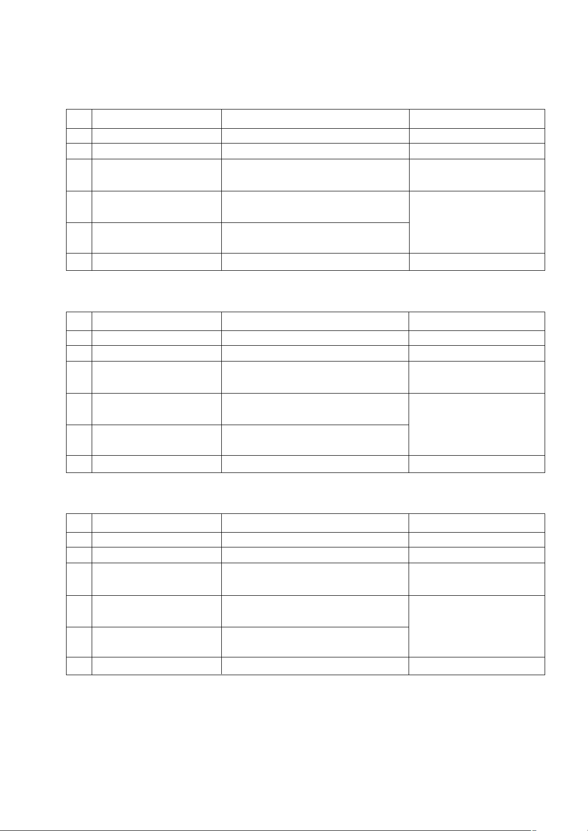
V Model General Specification
(1) EU Spec.(ZA)
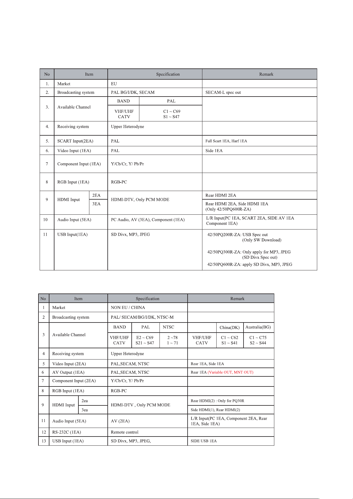
(2) NON-EU Spec.(TA)
Page 7
- 7 -
LGE Internal Use OnlyCopyright ©2009 LG Electronics. Inc. All right reserved.
Only for training and service purposes
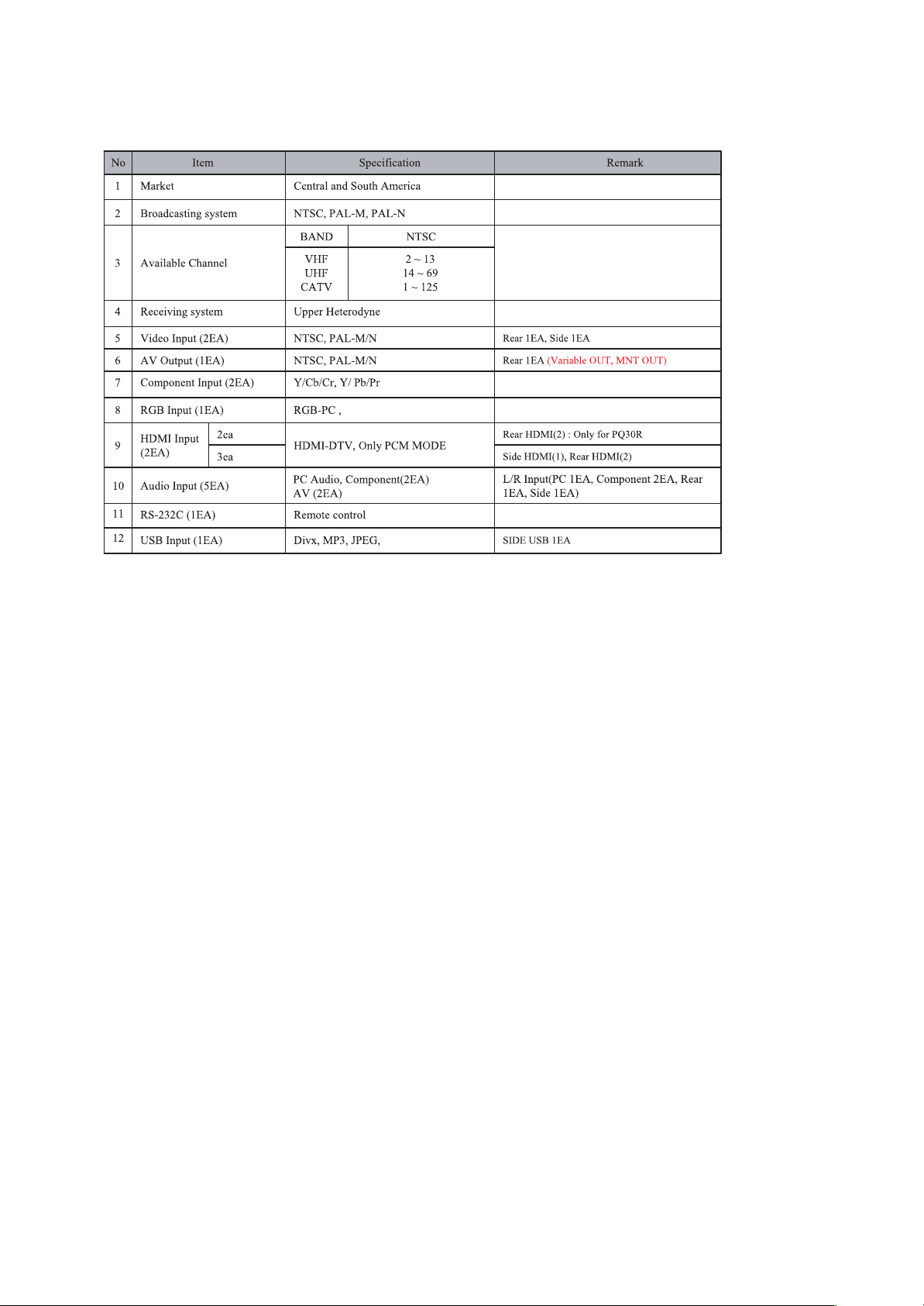
(3) Central and South America(MA)
Page 8
- 8 -
LGE Internal Use OnlyCopyright ©2009 LG Electronics. Inc. All right reserved.
Only for training and service purposes
ADJUSTMENT INSTRUCTION
1. Application Range
This spec sheet is applied to all of the PP91A/B chassis.
2. Specification
(1) Because this is not a hot chassis, it is not necessary to use
an isolation transformer. However, the use of isolation
transformer will help protect test instrument.
(2) Adjustment must be done in the correct order.
(3) The adjustment must be performed in the circumstance of
25±5°C of temperature and 65±10% of relative humidity if
there is no specific designation.
(4) The input voltage of the receiver must keep 100~240V,
50/60Hz.
(5) The receiver must be operated for about 5 minutes prior to
the adjustment when module is in the circumstance of over
15°
- In case of keeping module is in the circumstance of 0°C,
it should be placed in the circumstance of above 15°C for
2 hours
- In case of keeping module is in the circumstance of below
-20°C, it should be placed in the circumstance of above
15°C for 3 hours,.
3. S/W Program Download
3-1. Profile
This is for downloading the s/w to the flash memory of the
IC603
3-2. Equipment
(1) PC
(2) ISP_tool program
(3) Download jig
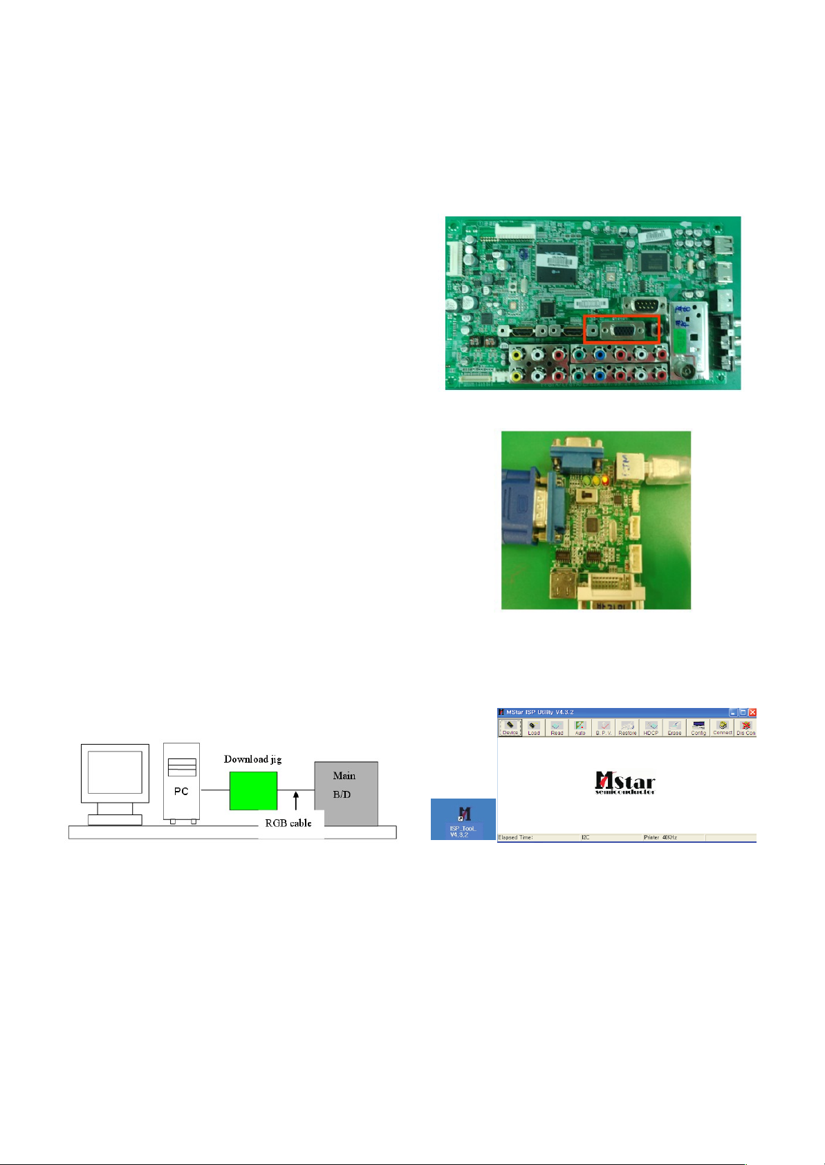
3-3. Connection Structure
3-4. Connection Condition
(1) IC name and circuit number : Flash Memory and IC603
(2) Use voltage : 3.3V (5 pin)
(3) SCL : 15 pin
(4) SDA : 12 pin
(5) Tact time : about 2min and 30seconds
3-5. Download Method (By using MSTAR JIG)
(1) Preliminary Steps
1) Connect the download jig to D-sub jack
2) Connect the PC to USB jack
(2) Download Steps
1) Execute ‘ISP Tool’ program in PC, then a main window will
be opened
Double click
Page 9
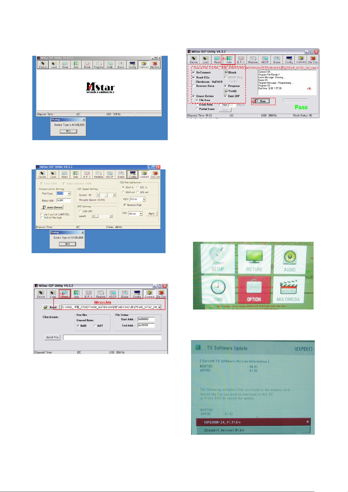
2) Click the connect button and confirm “Dialog Box”.
3) Click the Config button and Change speed
E2PROM Device setting : over the 350Khz
4) Read and write bin file
Click “(1)Read” tab, and then load download file(XXXX.bin)
by clicking “Read”.
5) Click “Auto(2)” tab and set as below
6) Click “Run(3)”.
7) After downloading, check “OK(4)” message.
3-6. Download Method (By using USB
Memory Stick)
[Caution]
- Using ‘power on’ button of the control R/C, power on TV.
- USB file (EPK) version must be bigger than downloaded
version of main B/D.
(1) Using ‘Power ON’ button of the control R/C, Power on TV.
(2) Insert the USB memory stick to the SET.
(3) Display USB loding message then, push the ‘Exit’ Key of
control R/C
(4) Push the ‘MENU’ Key and move the cusor ‘OPTION’ of
OSD ( Fig. 1)
* Caution: Don’t push the ‘OK’ key.Just cusor is on the
‘OPTION’ menu.
(5) Push the “7” key of control R/C continuously.
Then, Display “TV Software Update” Pop-up menu. (Fig. 2)
- 9 -
LGE Internal Use OnlyCopyright ©2009 LG Electronics. Inc. All right reserved.
Only for training and service purposes
( Fig. 1)
( Fig. 2)
Page 10
(6) Select SW file (XXXX.bin) you want, push the “OK” Key.
(7) S/W download process is excuted automatically.
4. PCB Assembly Adjustment Method
4-1. Option Adjustment Following BOM
Tool Option
Area Option
Option 1
Option 2
Option 3(Available for EU & Non EU model)
* Profile: Must be changed the option value because being
different with some setting value depend on module, inch
and market
* Equipment : Adjustment Remote Controller
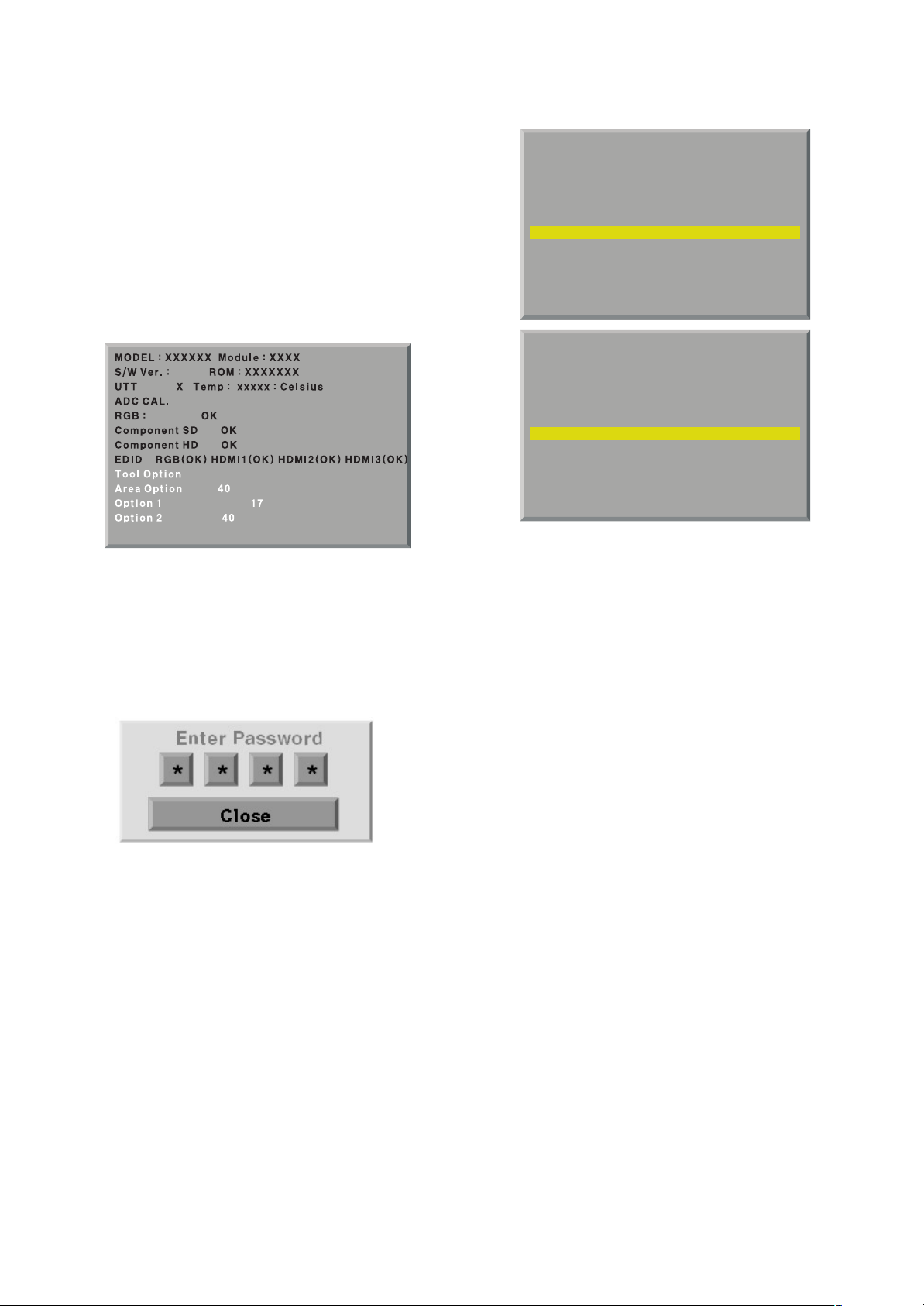
(1) Push the IN-START key in the Adjust R/C.
(2) Enter Password number. The value of Password is “0 0 0
0”.
(3) Input the Option Number that was specified in the BOM,
into the Shipping area.
(4) Select “Tool Option/ Area Option” by using
D/E(CH+/-)
key, and press the number key(0~9) consecutively
ex) If the value of Tool Option1 is 4, input the data using
number key “4” (Fig. 3)
Caution: Don’t Push “IN-STOP” key after PCB assembly
adjustment.
(5) EDID D/L Method
After software D/L or PCBA manufacturing, you can
download EDID Data.
When you adjust Tool Option, H6 Model EDID download
process is executed automatically
* If the model don’t have HDMI 3, HDMI 3 will be disappeared
at OSD Window.
Caution: When you adjust tool option, don’t connect HDMI or D-
sub cable.
If you connect some cable, EDID D/L process will be
failed.
(6) Adjustment method
Before PCBA check, have to change the Tool option and Area
option
[ About PDP
After done all adjustments, Press IN-START button and
compare Tool option and Area option value with its BOM, if it
is correctly same then Change “RF mode” and then unplug
the AC cable.
If it is not same, then correct it same with BOM and unplug AC
cable.
For correct it to the model’s module from factory JIG model.
[ Don’t push The IN-STOP KEY after completing the function
inspection.
- 10 -
LGE Internal Use OnlyCopyright ©2009 LG Electronics. Inc. All right reserved.
Only for training and service purposes
.
.
3.09
5
.
.
MODEL : XXXXXX Module : XXXX
S/W Ver. : X.XX ROM : XXXXXXX
UTT X Temp : xxxxx : Celsius
ADC CAL.
RGB : OK
Component SD OK
Component HD OK
EDID RGB(OK) HDMI1(NG) HDMI2(NG) HDMI3(NG)
Tool Option 4
Area Option 40
Option 1 17
Option 2 40
.
.
MODEL : XXXXXX Module : XXXX
S/W Ver. : X.XX ROM : XXXXXXX
UTT X Temp : xxxxx : Celsius
ADC CAL.
RGB : OK
Component SD OK
Component HD OK
EDID RGB(OK) HDMI1(OK) HDMI2(OK) HDMI3(OK)
Tool Option 4
Area Option 40
Option 1 17
Option 2 40
( Fig. 3)
Page 11

5. EDID(The Extended Display
Identification Data)
Originally H6(PP91A/B) Model EDID download process is
executed when you adjust Tool Option.
[ Caution
- Use the proper signal cable for EDID Download
- Never connect HDMI & D-SUB Cable at the same time.
- Use the proper cables below for EDID Writing
5-1. Profile: To be possible for plug and play
5-2. Equipment
(1) Adjusting PC with S/W for writing EDID Data.(S/W: EDID
TESTER Ver.2.5)
(2) A Jig for EDID Download
(3) Cable : Serial(9Pin or USB) to D-sub 15Pin cable, D-sub
15Pin cable, DVI to HDMI cable.
5-3. Connection Structure
Caution: Never connect HDMI & D-SUB Cable at the same time.
5-4. EDID Data
O WXGA EDID DATA(50inch)
<Analog(RGB) : 128bytes>
<HDMI 1 : 256bytes>
<HDMI 2 : 256bytes>
<HDMI 3 : 256bytes> SIDE HDMI(HDMI 3) is adjusted above
60Tool model
O XGA EDID DATA(42inch)
<Analog(RGB) : 128bytes>
- 11 -
LGE Internal Use OnlyCopyright ©2009 LG Electronics. Inc. All right reserved.
Only for training and service purposes
Connection Diagram of EDID
Page 12
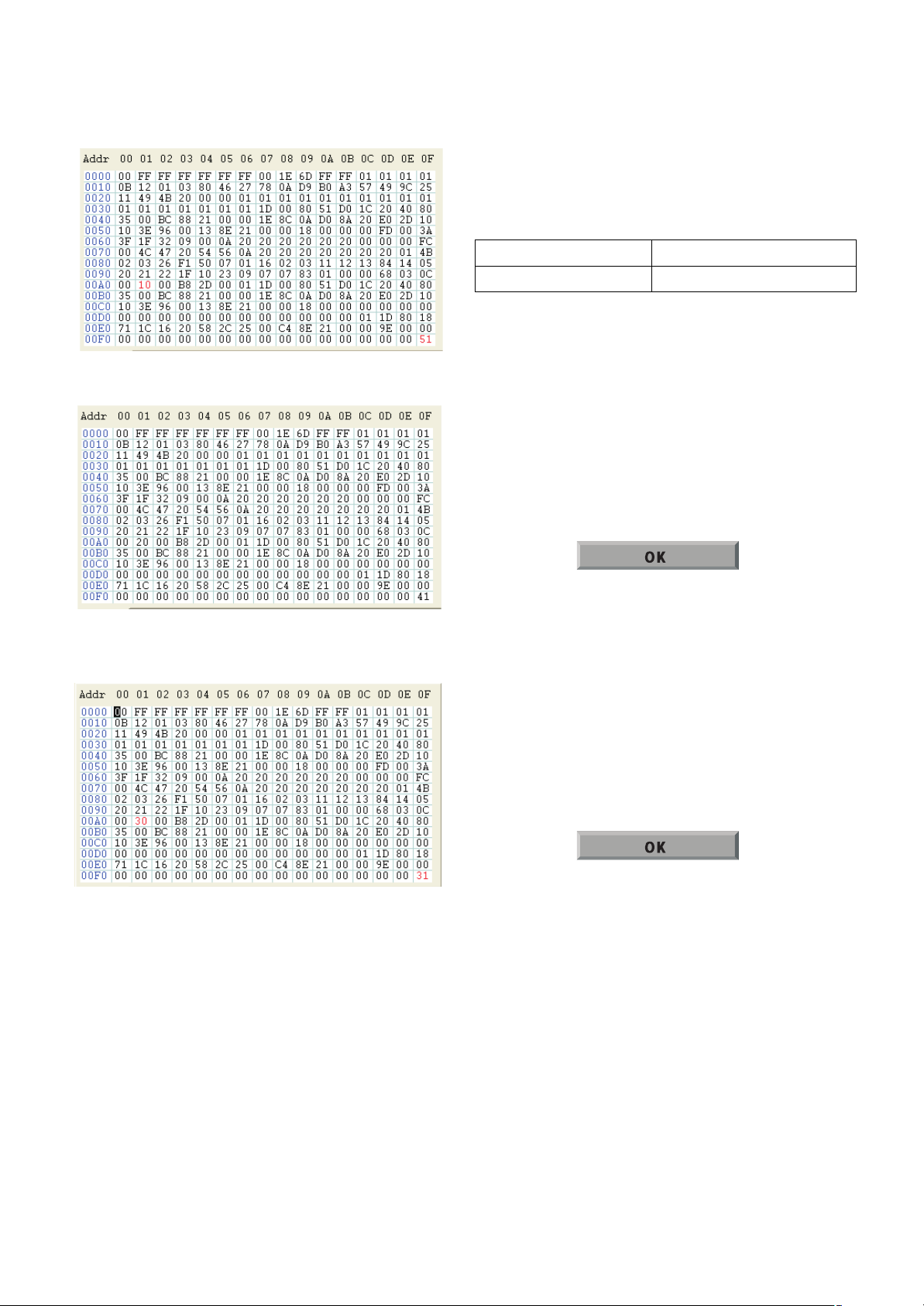
<HDMI 1 : 256bytes>
<HDMI 2 : 256bytes>
<HDMI 3 : 256bytes> SIDE HDMI(HDMI 3) is adjusted above
60Tool model
6. HDCP(High-Bandwidth Digital
Contents Protection) Download
HDCP download process is deleted in H6 models
In H6 models, it is usimg the EEPROM masking HDCP Key
7. Manual ADC Adjustment
(Component 1, RGB)
[Caution]
- Do not connect external input cable
- Adjustment result is applied to SET On/Off later.
* Adjustment is done using internal ADC, so input signal is not
necessary.
7-1. COMPONENT ADC (SD / HD)
(1) Convert to Component1 input source.
(2) Press ADJ key on R/C for adjustment.
(3) Enter Password number. The value of Password is “0 0 0
0”.
(4) Select “0. ADC calibration” by using
D/E(CH +/-) and press
ENTER(
V).
(5) Start ADC adjustment by using
F/G (VOL +/-) or press
ENTER(
V).
(6) ADC adjustment is executed automatically .
When ADC adjustment is finished, this OSD appear.
7-2. RGB input ADC
Auto RGB Gain/Offset Adjustment
(1) Convert to PC in Input-source
(2) Press ADJ key on R/C for adjustment.
(3) Enter Password number. The value of Password is “0 0 0
0”.
(4) Select “0. ADC calibration” by using
D/E(CH +/-) and press
ENTER(
V).
(5) Start ADC adjustment by using
F/G (VOL +/-) or press
ENTER(
V).
(6) ADC adjustment is executed automatically .
When ADC adjustment is finished, this OSD appear.
Notice : After All mode check, set the Speaker Volume “0”.
- 12 -
LGE Internal Use OnlyCopyright ©2009 LG Electronics. Inc. All right reserved.
Only for training and service purposes
RF input
NO SIGNAL or White noise
AV / Component / RGB input
NO SIGNAL
Page 13
Notice : From this sentence, All working is mass production.
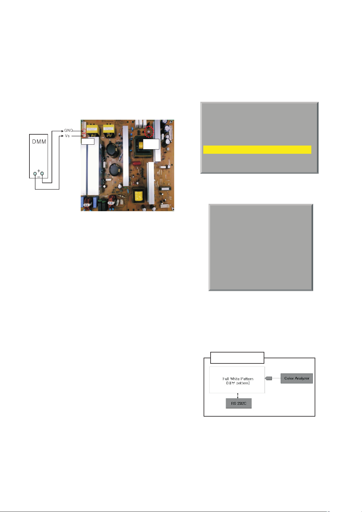
8. POWER PCB Assy Voltage
Adjustment
(Vs voltage Adjustment)
8-1. Test Equipment: D.M.M 1EA
8-2. Connection Diagram for Measuring
Refer to (Fig. 4)
8-3. Adjustment Method
(1) Vs Adjustment
1) Connect + terminal of D. M..M. to Vs pin of P702,
connect -terminal to GND pin of P702.
2) After turning VR901, voltage of D.M.M adjustment as
same as Vs voltage which on label of panel right/top (
deviation ; ±0.5V)
9. Adjustment of White Balance
9-1. Purpose and Principle for Adjustment
of the Color Temperature
(1) Purpose: Adjust the color temperature to reduce the
deviation of the module color temperature.
(2) Principle : To adjust the white balance without the
saturation, Fix the one of R/G/B gain to C0 and decrease
the others.
(3) Adjustment mode: Two modes of Cool, Warm and Medium
9-2. Required Equipment
(1) Remote controller for adjustment
(2) Color Analyzer : CA-100+ or CA-210 or same product
- PLASMA TV(ch : 10)
(3) Auto W/B adjustment instrument(only for Auto adjustment)
- Do the white balance adjustment under the 10LUX
[ Notice: When using the Color Analyzer with PDP,
recommend the CA-100 more than CA-210.
If CA-100 can not available, it is also good to use the CA-210.
(4) PC (for communication through RGB)
(5) Pattern Generator (MSPG-925FA etc.)
-Before white balance, press the ADJ key and select third
row like (Fig. 5)
-To enter White-balance mode, Enter Password Number “0
0 0 0” and select third row.
[ Caution: System control Host should be “DDC” for adjustment.
(6) Adjust W/B DATA, for all CSM, choose ‘COPY ALL’
9-3. Connecting Diagram of Equipment for
Measuring
(For Automatic Adjustment)
(Method 2, using RS-232C, You connect RS-232C Cable)
(1) Enter the adjustment mode of the white balance
- Enter the white balance adjustment mode at the same time
heat-run mode when pushing the power on by power only
key
- 13 -
LGE Internal Use OnlyCopyright ©2009 LG Electronics. Inc. All right reserved.
Only for training and service purposes
P811
Vs ADJ
VR901
(Fig. 4)
EZ ADJUST
0. ADC CALIBRATION : TV
1. ADC ADJUST
2. SUB B/C ADJUST
3. W/B ADJUST
4. WHITE PATTERN : OFF
5. EDID D/L
(Fig. 5)
3. W/B ADJUST
Mode : TV
TEMPERATURE : Medium
R-Gain. : 192
G-Gain. : 192
B-Gain. : 192
R-Offset : 128
G-Offset : 128
B-Offset : 128
COPY ALL
(Fig. 6)
Method 2-(RS-232C)
Page 14

- Maintain the white balance adjustment mode with same
condition of Heat-run
- Maintain after AC off/on in status of Heat-run pattern display
(2) Release the white balance adjustment mode
- Release the adjust mode after AC off/on or std-by off/on in
status of finishing the Hear-run mode
- Release the Adjust mode when receiving the aging off
command(F3 00 00) from adjustment equipment)
(3) Enter the adjust mode of white balance
- Enter the white balance adjustment mode with aging
command(F3, 00, FF)
9-4. Adjustment of White Balance for
Manual Adjustment
(method 3)
Adjustment mode: Three modes of Cool, Medium(Vivid) and
Warm
- Equipment : 1) Color analyzer(CA100+, CA210) should be
used in the calibrated ch by CS-1000(PDP :
CH10)
2) Adjustment remocon
- For manual adjustment, it is also possible by the following
sequence.
Operate the zero-calibration of the CA-100+ or CA-210, then
stick sensor to the module when adjusting.
(1) Select white pattern of heat-run by pressing “POWER ON”
key on remote control for adjustment then operate heat run
longer than 5 minutes. (recommend)
(If not executed this step, the condition for W/B will be
different)
(2) Changing to the AV mode by remote control.(Push front-
AV)
(3) Input external pattern(85% white pattern).
(4) Stick sensor to center of the screen and select each items
(Red/Green/Blue Gain and Offset) using
D/E(CH +/-) key
on R/C..
(5) Adjust R/ G/ B Gain using
F/G(VOL +/-) key on R/C.
(6) Adjust three modes of Cool, Medium(Vivid) and Warm as
below figure.
(Fix the one of R/G/B and change the others)
- Push the “VOL + “ key : Cool, Medium, Warm
[
Refer to the below case to know what value is fixed.
[CASE]
First adjust the coordinate much away from the target value(x, y).
1. x, y > target
1) Decrease the R, G.
2. x, y < target
1) First decrease the B gain,
2) Decrease the one of the others.
- In case of decreasing the x, decreasing the R : fix G
- In case of decreasing the y , decreasing the G : fix R
3. x > target , y < target
1) First decrease B, so make y a little more than the target.
2) Adjust x value by decreasing the R
4. x < target , y > target
1) First decrease B, so make x a little more than the target.
2) Adjust x value by decreasing the G
(7) When adjustment is completed, Exit adjustment mode
using EXIT key on R/C.
9-5. Connecting diagram of Equipment for
Measuring
(For Automatic Adjustment)
(method 1, using IIC, You connect RGB Cable)
(1) Enter the adjustment mode of the white balance
- Enter the white balance adjustment mode at the same time
heat-run mode when pushing the power on by power only
key
- Maintain the white balance adjustment mode with same
condition of Heat-run
- Maintain after AC off/on in status of Heat-run pattern display
(2) Release the white balance adjustment mode
- Release the adjust mode after AC off/on or std-by off/on in
status of finishing the Hear-run mode
- push the “power on” key(IIC Mode) on Adjust remotecontroller.
- Release the Adjust mode when receiving the aging off
command(F3 00 00) from adjustment equipment)
(3) Enter the adjust mode of white balance
- Enter the white balance adjustment mode with aging
command(F3, 00, FF)
O Color Temperature & Color Coordinates Setting
- When adjusting the Color Temperature, Color Analyzer CA210(Matrix should be corrected through CH10 of CS-1000)
should be used. When CA-210 have used, it don’t need to fit
the CH10.
- Adjust the Color Temperature based below adjustment color
coordinates.
O Target Value CA-210(LCD : CH 9, PDP : CH10), CA-100(PDP)
- 14 -
LGE Internal Use OnlyCopyright ©2009 LG Electronics. Inc. All right reserved.
Only for training and service purposes
+0.0036,500K
Warm
+0.0009,300K
Medium
+0.00011,000K
Cool 0.276±0.002
0.285±0.002 0.293±0.002
0.329±0.002
0.313±0.002
0.283±0.002
YX
uvTemp
Color coordinate
Mode
Method 1-(I2C)
Page 15
(Standard color coordinate and temperature when using the
CA-100+ or CA210 equipment)
O Above optical characteristics are should be measured by
following condition.
- 15 -
LGE Internal Use OnlyCopyright ©2009 LG Electronics. Inc. All right reserved.
Only for training and service purposes
+0.0036,500K
Warm
+0.0009,300K
Medium
+0.00011,000K
Cool 0.276±0.002
0.285±0.002 0.293±0.002
0.329±0.002
0.313±0.002
0.283±0.002
YX
uvTemp
Color coordinate
Mode
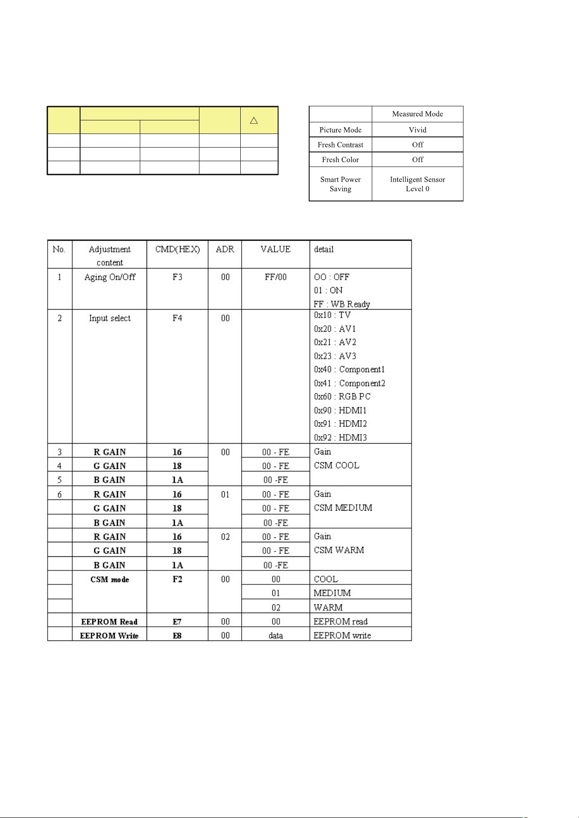
O DDC Adjustment Command Set
[ R/G/B GAIN max value : C0
Adjustment
Adjustment
Adjustment
Page 16
- 16 -
LGE Internal Use OnlyCopyright ©2009 LG Electronics. Inc. All right reserved.
Only for training and service purposes
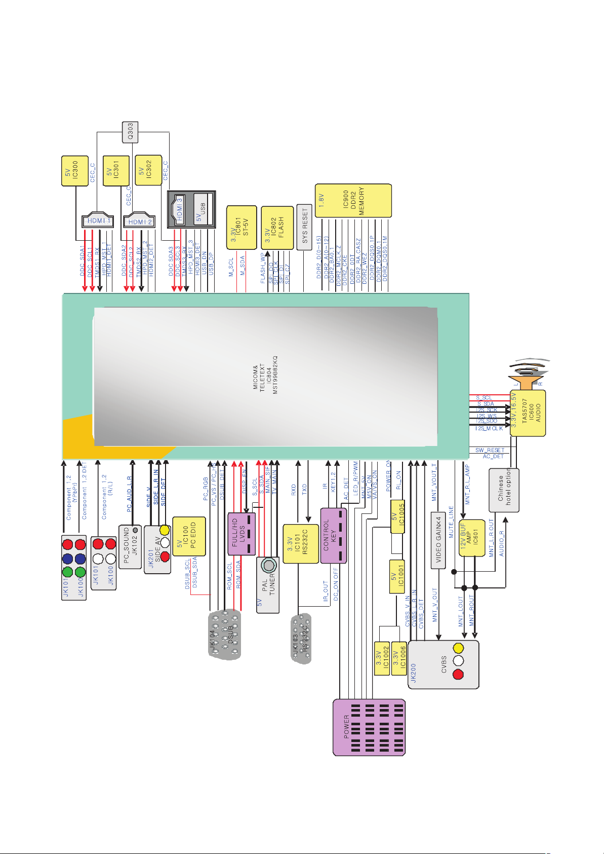
BLOCK DIAGRAM
Page 17
A10
900
901
400
520
590
240
250
300
305
301
303
560
310
330
302
200
120
580
260
270
603
602
601
501
570
A2
LV1
201
203
205
204
206
202
- 17 -
LGE Internal Use Only
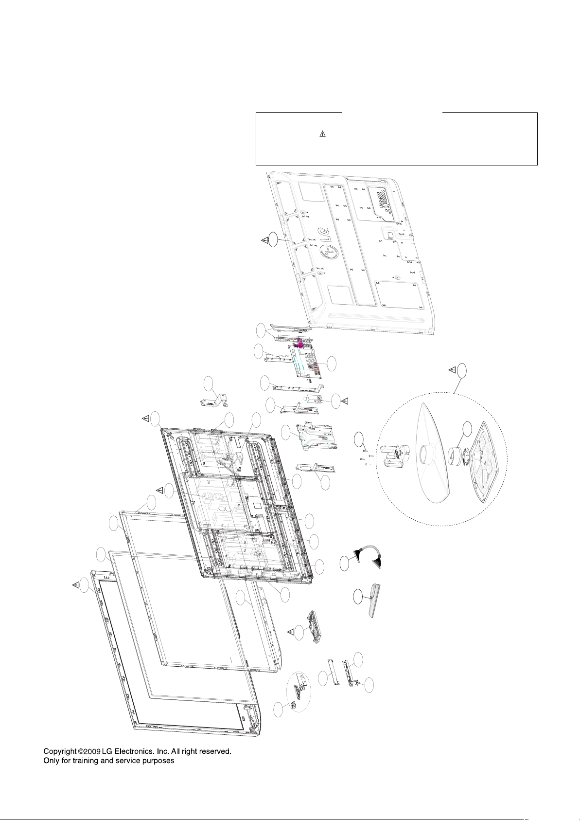
EXPLODED VIEW
Many electrical and mechanical parts in this chassis have special safety-related characteristics. These
parts are identified by in the Schematic Diagram and EXPLODED VIEW.
It is essential that these special safety parts should be replaced with the same components as
recommended in this manual to prevent X-RADIATION, Shock, Fire, or other Hazards.
Do not modify the original design without permission of manufacturer.
IMPORTANT SAFETY NOTICE
Page 18
Copyright ⓒ 2009 LG Electronics. Inc. All right reserved.
Only for training and service purposes
LGE Internal Use Only
Page 19

Copyright ⓒ 2009 LG Electronics. Inc. All right reserved.
Only for training and service purposes
LGE Internal Use Only
Page 20
Copyright ⓒ 2009 LG Electronics. Inc. All right reserved.
Only for training and service purposes
LGE Internal Use Only
Page 21

Copyright ⓒ 2009 LG Electronics. Inc. All right reserved.
Only for training and service purposes
LGE Internal Use Only
Page 22

Copyright ⓒ 2009 LG Electronics. Inc. All right reserved.
Only for training and service purposes
LGE Internal Use Only
Page 23

Copyright ⓒ 2009 LG Electronics. Inc. All right reserved.
Only for training and service purposes
LGE Internal Use Only
Page 24

Copyright ⓒ 2009 LG Electronics. Inc. All right reserved.
Only for training and service purposes
LGE Internal Use Only
Page 25

Copyright ⓒ 2009 LG Electronics. Inc. All right reserved.
Only for training and service purposes
LGE Internal Use Only
Page 26

Copyright ⓒ 2009 LG Electronics. Inc. All right reserved.
Only for training and service purposes
LGE Internal Use Only
Page 27

Page 28

PDP TV Repair Process Index
Copyright ⓒ 2009 LG Electronics. Inc. All right reserved.
Only for training and service purposes
LGE Internal Use Only
No. Symptom (L) Symptom (M) Page Remark
1 No Picture/Sound OK 1
2 No Picture/No sound 2
3 Mal-discharge/Noise/dark picture 3
4 Picture broken/Freezing 4
5 Vertical bar/ Horizontal Bar 5
6
7 Turn off (Instant, under watching) 7
9 E. General function Problem Remote control & Local switch checking 9
A. Picture Problem
No Power (Not turn on) 6
B. Power Problem
8No sound/ Sound distortionC. Sound Problem8
First of all, Check whether there is SVC Bulletin in GCSC System for these model.
Page 29

Repair Process
Copyright ⓒ 2009 LG Electronics. Inc. All right reserved.
Only for training and service purposes
LGE Internal Use Only
PDP TV
Symptom
A. Picture Problem
No Picture/Sound OK
Making
Revision
2009. 2 . 1
First of all, Check whether all of cable between board was inserted properly or not.
(Main B/D↔ Power B/D, Power B/D↔ Y-sus B/D,Y-Sus B/D ↔Z-Sus B/D,LVDS Cable,Speaker Cable,IR B/D Cable,,,)
☞A1
Check Module pattern
by using “TILT” key
on SVC R/C
Normal
N
☞A3
Check
Vs, Va
☞A2
Check
Y
Sound
Normal
N
Move
Power problem
Section
Sound
OK
Move
No Picture/No sound
Section
☞A5~A6
Check voltage
Y
Y
. -V
. VSC
. VZB
☞A8~A11
1. Check Y-Sus/ Z-Sus Board
2. Replace defective B/D
Y
N
Check
LVDS Cable
Normal
Replace
Main B/D
Y
Close
N
☞A13
☞A12
Check B+ Voltage
Y
Normal Normal
N
on Power Board
/ Control Board
.Check B+(5V)
N
Move
Power problem
Section
1.Check Control Board
. LED on
Y
. Crystal(X101)
. 1.8V, 3V, 5V FET
. Rom update
2.Replace Control B/D
1/9
<SVC R/C & Pattern>
※Refer to the Module label for each voltage
-VY VSC VZB
1
☞A4
Page 30

Repair Process
Copyright ⓒ 2009 LG Electronics. Inc. All right reserved.
Only for training and service purposes
LGE Internal Use Only
PDP TV
☞A1
Check Module pattern
by using “TILT” key
on SVC R/C
No Picture/ Sound Ok
Symptom
Normal
Move
Section
A. Picture Problem
No Picture/No Sound
Making
Revision
2009. 2 . 1
2/9
☞A2
Check
Y
Sound
N
Sound
OK
Y
N
Check
LVDS Cable
Normal
Replace
Main B/D
Y
Close
N
☞A26
N
Check IR operation
Normal
Y
Power
LED ON?
N
Repair/Replace
IR B/D
Y
OSD
appear?
Check Input signal
. RF Cable connection
Y
. SCART Cable connection
. HDMI Cable connection
N
. Component Cable …
Latest S/W update
from GCSC
(Firmware Management)
Normal
Close
N
Y
2
Replace
Main B/D
Page 31

Repair Process
Copyright ⓒ 2009 LG Electronics. Inc. All right reserved.
Only for training and service purposes
LGE Internal Use Only
PDP TV
Check
Picture problem
Type
☞A14
Mal-discharge
Symptom
Dot
type
Scan
Type
A. Picture Problem
Mal-discharge/Noise/dark picture
☞A15
Check CTRL ROM Ver.
and
Rom Upgrade
☞A5~A6
Check voltage
Y / VSC
. –V
(Y-Sus B/D)
Normal
Picture?
N
Replace
Y-Sus B/D
Normal
Picture?
Close
☞A16
Check
Y
Y Drive B/D
Replace B/D
Y
&
Making
2009. 2 . 1
Revision
N
Replace
Control board
Normal
Picture?
Y
Close
☞A13
Normal
Picture?
Close
N
1.Check Control B/D
2.Replace Board
Y
☞A17
※Check Discharge resistance (10Ω 2~3ea)
on Power B/D before replace Y Drive B/D
3/9
N
Replace
Module
N
Normal
Picture?
Y
Close
Picture Noise
Dark Picture
Check RF Cable
Connection
Picture mode
Check
setting
Normal
Picture?
Close
Normal
Picture?
Y
Close
N
Check Tuner
& Replace
Y
☞A9(42G2),A11(50G2)
N
1. Check Z-Sus Board
2. Replace Board
Normal
Picture?
Y
Close
N
Replace
Module
3
Page 32

Repair Process
Copyright ⓒ 2009 LG Electronics. Inc. All right reserved.
Only for training and service purposes
LGE Internal Use Only
PDP TV
☞A21
Check RF Signal level
Normal
Signal?
N
Check RF Cable
Connection
1. Reconnection
2. Install Booster
Normal
Picture?
Y
Close
Y
N
Symptom
A. Picture Problem
Picture broken/Freezing
. By using Digital signal level meter
. By using Diagnostics menu on OSD
( Menu→Setup→Diagnostic)
- Signal strength (Normal : over 50%)
- Signal Quality (Normal: over 50%)
Check whether other equipments have problem or not.
(By connecting RF Cable at other equipment)
→ DVD Player ,Set-Top-Box, Different maker TV etc
Normal
Picture?
Contact with signal distributor
or broadcaster (Cable or Air)
Y
N
Check
S/W Version
SVC
Bulletin?
Y
S/W Upgrade
Normal
Picture?
Y
Making
2009. 2 . 1
Revision
■ Menu→Setup →Booster
Booster menu
N
On→Off: Check
Off→On: Check
Tuner soldering
N
Normal
Picture?
N
Check
Replace
Main B/D
4/9
Y
Close
Close
※ ’09 years new model apply chip tuner
so, chip tuner is soldered on main PCB
[ Chip Tuner: IC500(XC5000) ]
4
Page 33

Repair Process
Copyright ⓒ 2009 LG Electronics. Inc. All right reserved.
Only for training and service purposes
LGE Internal Use Only
PDP TV
☞A19
Check
defect type
Vertical
Line/Bar
Half
No picture
Symptom
Regular
Vertical
Line / Bar
Irregular
Vertical
Line / Bar
☞A18
1.Check X B/D
2.Replace Board
A. Picture Problem
Vertical bar/ Horizontal Bar
☞A1
Check Module pattern
by using “TILT” key
on SVC R/C
☞A20
Check connection
of Connector
(COF,TCP)
on CTRL B/D , X B/D
1.Connector re-connection
2.Eliminate foreign material on Connector
Normal
Picture?
Normal
N
N
Y
Replace
Module
Normal
Pattern?
☞A13
1.Check CTRL B/D
2.Replace Board
N
☞A13
1.Check CTRL B/D
2.Replace Board
Making
2009. 2 . 1
Revision
Y
Replace
Module
※CTRL B/D: Control board
Normal
Picture?
Close
N
Y
5/9
Check Main B/D
Replace Module
(If Main B/D doesn’t cause)
☞A20
Horizontal
Line/Bar
Check connection
of Connector (FPC)
on Y Drive B/D
Y
Close
☞A16
Y
Normal
N
1.Connector re-connection
2.Eliminate foreign material on FFC
1. Check Y Drive B/D
2. Replace Board
※ H-Line’s Cause is rare CTRL B/D
Normal
Picture?
Y
Close
N
1.Check CTRL B/D
2.Replace Board
Normal
Picture?
Close
N
Replace
Module
Y
5
Page 34

Repair Process
Copyright ⓒ 2009 LG Electronics. Inc. All right reserved.
Only for training and service purposes
LGE Internal Use Only
PDP TV
Check
Power LED
. Stand-By: Red
. Operating: Green
Check Power cord
was inserted properly
☞A27
Mechanical Power switch
on Local control of TV
☞A22
Symptom
Power LED
ON?
N
Check & Repair
Normal
?
Check ST-BY 5V
on Power Board
Y
N
B. Power Problem
No Power (Not turn on)
☞A26
DC Power on
Y
by pressing Power Key
On Remote control
Normal
Close
※ ’09 years new model apply mechanical power switch
to reduce power consumption in stand-by status.
If mechanical power switch off
→ Doesn’t turn on by remote control
→ Doesn’t appear LED light
Close
N
Y
Check
R/C IR Operation
Making
Revision
Normal
2009. 2 . 1
Y
N
Repair/Replace
6/9
IR B/D
Normal
Voltage?
Y
N
☞A22
Check
AC DET Signal
on Power B/D
Normal
Signal?
N
☞A23
Check Power B/D
Replace Power B/D
☞A22
Y
Check
RL_ON Signal
on Power B/D
☞A22
Normal
Signal?
Check Main B/D
Replace Main B/D
Y
N
Check
the other pin’s
Output voltage
on Power B/D
Normal
Y
Close
N
Power B/D
Replace
6
Page 35

Repair Process
Copyright ⓒ 2009 LG Electronics. Inc. All right reserved.
Only for training and service purposes
LGE Internal Use Only
PDP TV
Symptom
※ To check Power B/D Protection
Instant
Turn off
Turn off
Under watching
Turn on after pull out connector
between Power B/D & Y-Sus
“Off Timer”
Set?
“Off timer”
Function off
B. Power Problem
Turn off (Instant, under watching)
Power LED
Green?
☞A23
Check Power B/D
Replace Power B/D
☞A24
N
Y
Check
Power Off History
N
RCU Off
KEY Off
2HOUR Off
NO Signal Off
Don’t appear
Power Off History
Y
Making
2009. 2 . 1
Revision
☞A8~A11
1. Check Y-Sus/ Z-Sus Board
(especially Short or Open)
2. Replace defective B/D
This is not problem
Normal operation
Move
No Power problem
Section
7/9
7
Page 36

Repair Process
Copyright ⓒ 2009 LG Electronics. Inc. All right reserved.
Only for training and service purposes
LGE Internal Use Only
PDP TV
1.No sound( If HDMI Input only have no sound, upload EDID data)
Check
“Speaker ON/Off” setting
in OSD Menu
2.Sound distortion & sound drop
Check Input signal
→Cable connection
→Cable open
-RF & external
(HDMI,SCART,,,)
Symptom
Normal
Sound?
Normal
Sound?
Y
Close
Y
Close
N
No sound/ Sound distortion
☞A25
N
AVL off/on
Clear voiceⅡ off/on
Check Speaker
jack connection
& Speaker Cable open
Check
Normal
Sound?
Close
Y
C. Sound Problem
Making
Revision
Normal
Sound?
Y
Close
Problem in all input
N
Problem in only DTV(Case 1)
Problem in external input(Case 2)
N
(SCART,HDMI,,,)
SVC
Bulletin?
N
☞A22
Check 17V
(Audio IC B+)
on Power B/D
2009. 2 . 1
Y
Check Audio IC Short
Replace Main B/D
Apply
SVC Bulletin
(S/W Upgrade etc)
Normal
voltage?
N
Y
Normal
Sound?
N
☞A23
Check Power B/D
Replace Power B/D
8/9
Close
Y
Check whether Problem happen
in same output of other equipments or not.
(By connecting same output cable of other equipment)
→ DVD Player ,Set-Top-Box, different maker TV etc
Normal
Sound?
Y
Explain customer that
Cause is RF Signal’s problem (Case 1)
Cause is Equipment’s problem (case 2)
N
8
SVC
Bulletin?
Y
Apply
SVC Bulletin
(S/W Upgrade etc)
Normal
Sound?
Check Audio IC
Replace Main B/D
Y
NN
Close
Page 37

Repair Process
Copyright ⓒ 2009 LG Electronics. Inc. All right reserved.
Only for training and service purposes
LGE Internal Use Only
PDP TV
1. Remote control(R/C) operating error
Check R/C itself
Operation
Check R/C Operating
When turn off light
in room
If R/C operate,
Explain the customer
cause is interference
from light in room.
Symptom
Normal
operating?
N
Check & Replace
Baterry of R/C
operating?
Replace R/C
Y
Normal
N
Remote control & Local switch checking
☞A26
Check & Repair
Cable connection
Connector solder
Close
D. General Function Problem
Normal
operating?
Y
Close
☞A26
N
Check B+ 5V
On Main B/D
Making
2009. 2 . 1
Revision
☞A26
Normal
Voltage?
N
Y
Check IR
Output signal
☞A12
Check 5v on Power B/D
Replace Power B/D or
Replace Main B/D
(Power B/D don’t have problem)
9/9
Replace
Main B/D
Normal
Signal?
N
Repair/Replace
IR B/D
Y
2. Local(Mechanical) switch operating error
Check R/C
Operation
Normal
operating?
N
Move
Power problem
Section
☞A27
Check & Repair
Y
Cable connection
Connector solder
Normal
operating?
Y
Close
☞A28
Check & Replace
N
Assembly status
(Key PCB + tool )
9
Normal
operating?
Y
Close
☞A27
N
Check Key
Output signal
Replace
Main B/D
Normal
Signal?
N
Repair/Replace
Local switch B/D
Y
Page 38

PDP TV Repair Process Reference data Index
Copyright ⓒ 2009 LG Electronics. Inc. All right reserved.
Only for training and service purposes
LGE Internal Use Only
No. Symptom Detail Page Remark
1
2
3
4
Check Module pattern by Tilt key A1
Audio check method
Check Va, Vs on Power Board
PDP Module Label Information
A2
A3
A4
Check & Adjust –VY,VSC,VZB voltage
5
6 Fuse Checking Method A7
7 Y-Sus Board Checking Method(42G2) A8
8 Z-Sus Board Checking Method(42G2) A9
9 Y-Sus Board Checking Method(50G2) A10
10 Z-Sus Board Checking Method(50G2) A11
11 Check 5V, 12V on Power B/D A12
12 Control Board Checking Method(42G2/50G2) A13
Picture Problem
- 42G2 –VY,VSC(Y-Sus) / VZB(Z-Sus)
- 50G2 –VY,VSC(Y-Sus) / VZB(Z-Sus)
A5
A6
13 Mal discharge Symptom Picture A14
14 PDP Module Rom Ver. Checking method A15
15 Y Drive B/D Checking method A16
16 Check Discharge resistor on Power B/D A17
17 (Half picture) X- B/D Checking method(42/50G2) A18
Next page Continued
Page 39

PDP TV Repair Process Reference data Index
Copyright ⓒ 2009 LG Electronics. Inc. All right reserved.
Only for training and service purposes
LGE Internal Use Only
No. Symptom Detail Page Remark
18
19 Connector Type on PDP Module A20
20 RF Signal level Checking method A21
21 Check voltage on Power board A22
22
23 Check Power off History A24
24 Speaker cable checking method A25
25
26 Check Local switch operating A27
27 Check Local switch assembly status A28
Picture Problem
Power Problem
Sound Problem
General Function Problem
Defect type cause by PDP Module A19
Power board Checking Method A23
Check Remote control IR operation A26
Page 40

Repair Process-Reference data
Copyright ⓒ 2009 LG Electronics. Inc. All right reserved.
Only for training and service purposes
LGE Internal Use Only
PDP TV
Symptom
Item
A. Picture Problem
Check Module pattern by Tilt key
Making
Revision
2009. 2 . 1
A1
Tilt Key
You can see 20 types patterns by using TILT Key on SVC Remote controller (except Old model)
< CHECK Item >
1. Dead pixel 2.Image sticking 3.Mal discharge 4.Module defect (V-Line/Bar, H-Line/Bar,,,)
5. In case of no picture, you can judge defect cause (Module or Main B/D)
- If patterns appear, defect cause is Main B/D
A1
Page 41

Repair Process-Reference data
Copyright ⓒ 2009 LG Electronics. Inc. All right reserved.
Only for training and service purposes
LGE Internal Use Only
PDP TV
Symptom
A. Picture Problem
Audio check method
Making
Revision
Jack for Speaker connection
2009. 2 . 1
A2
1.Check Audio output by using oscilloscope
GND ↔ R+ or R- or L+ or L-
Audio output waveform
2.Check whether speaker jack was inserted properly or not.
A2
Page 42

Repair Process-Reference data
Copyright ⓒ 2009 LG Electronics. Inc. All right reserved.
Only for training and service purposes
LGE Internal Use Only
PDP TV
Y-Sus Board
Va, Vs on Y-Sus B/D Va, Vs on Power B/D
Symptom
Check Va, Vs on Power Board
PDP Module Label
Power Board
Z-Sus Board
Control Board
Main Board
A. Picture Problem
Making
2009. 2 . 1
Revision
▶ Check Va & Adjust Va Voltage
(Refer to the Module label for Va specification)
▶ Check Vs & Adjust Vs Voltage
(Refer to the Module label for Vs specification)
A3
Check Va, Vs
Va Adjustment
(VR502)
Vs Adjustment
(VR901)
A3
Page 43

Repair Process-Reference data
Copyright ⓒ 2009 LG Electronics. Inc. All right reserved.
Only for training and service purposes
LGE Internal Use Only
PDP TV
①
②
③
④
⑤
⑥
-Vy Vsc Vzb
Symptom
⑦
A. Picture Problem
PDP Module Label Information
PDP Module Label Information.
⑧
Making
Revision
2009. 2 . 1
A4
⑨⑩
⑪
⑫
⑬
⑭
⑮
A4
Page 44

Repair Process-Reference data
Copyright ⓒ 2009 LG Electronics. Inc. All right reserved.
Only for training and service purposes
LGE Internal Use Only
PDP TV
Symptom
Check & Adjust –VY,VSC,VZB voltage
Voltage Check & Adjustment : 42G2
<Module Label>
-VY VSC VZB
1. -Vy (-175V) on Y-Sus B/D
. Check Point: R201
. Adjustment Point: VR502
A. Picture Problem
Y-Sus Board
Making
Revision
2009. 2 . 1
A5
Fuse
2. Vsc (140V) on Y-Sus B/D
- Check Point: R520 –J263
- Adjustment Point: VR501
-VYAdjustment
VSCAdjustment
A5
Page 45

Repair Process-Reference data
Copyright ⓒ 2009 LG Electronics. Inc. All right reserved.
Only for training and service purposes
LGE Internal Use Only
PDP TV
Voltage Check & Adjustment : 42G2
<Module Label>
-VY VSC VZB
Symptom
Check & Adjust –VY,VSC,VZB voltage
Adjustment Point
A. Picture Problem
Making
Revision
Z-Sus Board
2009. 2 . 1
A5
3. VZB (80V) on Z-Sus B/D
. Check Point: R50↔J221
A5
Page 46

Repair Process-Reference data
Copyright ⓒ 2009 LG Electronics. Inc. All right reserved.
Only for training and service purposes
LGE Internal Use Only
PDP TV
Symptom
Check & Adjust –VY,VSC,VZB voltage
Voltage Check & Adjustment : 50G2
<Module Label>
-VY VSC VZB
1. -Vy (-185V) on Y-Sus B/D
. Check Point: R201
. Adjustment Point: VR502
A. Picture Problem
Making
Revision
Y-Sus Board
2009. 2 . 1
A6
Fuse
2. Vsc (135V) on Y-Sus B/D
- Check Point: R202
- Adjustment Point: VR501
A6
-VYAdjustment
Vsc Adjustment
ⓒ LG Electronics. Inc.2009
Page 47

Repair Process-Reference data
Copyright ⓒ 2009 LG Electronics. Inc. All right reserved.
Only for training and service purposes
LGE Internal Use Only
PDP TV
Voltage Check & Adjustment : 50G2
<Module Label>
-VY VSC VZB
Symptom
Check & Adjust –VY,VSC,VZB voltage
A. Picture Problem
Making
Revision
Fuse
2009. 2 . 1
A6
Z-Sus Board
3. VZB (80V) on Z-Sus B/D
. Check Point: R271↔J125
. Adjustment Point: VR200
Adjustment Point
A6
ⓒ LG Electronics. Inc.2009
Page 48

Repair Process-Reference data
Copyright ⓒ 2009 LG Electronics. Inc. All right reserved.
Only for training and service purposes
LGE Internal Use Only
PDP TV
Symptom
A. Picture Problem
Fuse Checking Method
< Fuse check >
< DMM mode >
Pic. 2.Pic. 1.
Making
Revision
2009. 2 . 1
A7
1) Sound comes, the fuse is OK.
2) If Fuse is defects, it should check again voltage of 5V, Va, Va after replacing the fuse.
3) In case there are no voltage of 5V, Va, Vs, the board is failure, it need to replace the board.
A7
ⓒ LG Electronics. Inc.2009
Page 49

Repair Process-Reference data
Copyright ⓒ 2009 LG Electronics. Inc. All right reserved.
Only for training and service purposes
LGE Internal Use Only
PDP TV
▣ Check Method
① Check whether there is short between Vs & GND of P201 Connector
② Check FUSE open
③ Check voltage of Diode , FET by using Digital Multi Meter
HS1
SUS UP/Down FET & Diode
Q11~Q16 FET(6ea)
D11 , D12 Diode(2ea)
▣ Measuring Method
Symptom
Y-Sus Board Checking Method(42G2)
HS2
PASS/ER UP/Down FET , Diode
Q21~Q23 FET(3ea)
D21~D24 Diode(4ea)
A. Picture Problem
Making
2009. 2 . 1
Revision
HS1 HS2
A8
Fuse
<Specification>
Position
HS1
HS2
Fuse
Diode FET
Circuit No.Direction
Q16Q15D11,12Q11~Q14
0.3~0.4V0.4~0.5V0.3~0.4V0.3~0.4VForward
OL(Overload)Reverse
D21~D24Q21~Q23
0.3~0.4V0.4~0.5VForward
OL(Overload)Reverse
A8
ⓒ LG Electronics. Inc.2009
Page 50

Repair Process-Reference data
Copyright ⓒ 2009 LG Electronics. Inc. All right reserved.
Only for training and service purposes
LGE Internal Use Only
PDP TV
▣ Check Method
① Check 5V, 15V input voltage on P2 Connector
② Check VS input voltage on P3 Connector
③ Check voltage of Diode , FET by using Digital Multi Meter)
HS1
HS1
Q506 Q505 D506 Q504 Q503 D505
▣
Measuring Method
Symptom
Z-Sus Board Checking Method(42G2)
HS2
HS2
D501 D502 Q501 Q502 D503 D504
A. Picture Problem
Making
Revision
HS1
2009. 2 . 1
A9
HS2
Diode
<Specification>
Position
HS1
HS2
FET
P3
P2
ClassifyDirection
DiodeFET
0.3~0.4V0.4~0.5VForward
OL(Overload)Reverse
0.3~0.4V0.3~0.4VForward
OL(Overload)Reverse
A9
ⓒ LG Electronics. Inc.2009
Page 51

Repair Process-Reference data
Copyright ⓒ 2009 LG Electronics. Inc. All right reserved.
Only for training and service purposes
LGE Internal Use Only
PDP TV
▣ Check Method
① Check whether there is short between Vs & GND of P201 Connector
② Check FUSE open
③ Check voltage of Diode , FET by using Digital Multi Meter
HS1 HS2 HS3
Q31,Q32,Q34 FET(3ea)
D32~D36 Diode(4ea)
▣ Measuring Method
Symptom
Q22,Q23 FET(2ea)
D21 Diode(1ea)
Y-Sus Board Checking Method(50G2)
Q11~Q13, Q16~Q18 FET (6ea)
D11 Diode (1ea)
A. Picture Problem
Making
Revision
Fuse
2009. 2 . 1
A10
HS3
HS1
<Specification>
Position
HS1
HS2
HS3
FET Diode
Circuit No.Direction
D32~D36Q34Q31,32
0.4~0.5V0.3~0.4V0.4~0.5VForward
OL (Overload)Reverse
D21Q22,23
0.3~0.4V0.3~0.4VForward
OL(Overload)Reverse
Q16~Q18D11Q11~Q13
0.4~0.5V0.3~0.4V0.3~0.4VForward
OL(Overload)Reverse
A10
HS2
Fuse
ⓒ LG Electronics. Inc.2009
Page 52

Repair Process-Reference data
Copyright ⓒ 2009 LG Electronics. Inc. All right reserved.
Only for training and service purposes
LGE Internal Use Only
PDP TV
▣ Check Method
① Check 15V input voltage on P100 Connector
② Check 5V,VS input voltage on P101 Connector
③ Check FUSE open
④ Check voltage of Diode , FET by using Digital Multi Meter)
D301 D302 Q301 Q303 D305
D303 Q304 D306
▣
Measuring Method
Symptom
HS200
HS200
Z-Sus Board Checking Method(50G2)
HS201
HS201
Q318 Q315 Q313 Q312
Q317 Q314 Q311
A. Picture Problem
Making
Revision
2009. 2 . 1
A11
P101
Fuse
D311D312
HS200
HS2
HS201
Diode
FET
<Specification>
Position
HS200
HS201
ClassifyDirection
OL(Overload)Reverse
0.5V~0.6V
OL(Overload)Reverse
P100
DiodeFET
0.3V~0.4V0.4V~0.5VForward
D311,312Q313~Q318Q311~312
0.3V~0.4V0.3V~0.4VForward
A11
ⓒ LG Electronics. Inc.2009
Page 53

Repair Process-Reference data
Copyright ⓒ 2009 LG Electronics. Inc. All right reserved.
Only for training and service purposes
LGE Internal Use Only
PDP TV
▣ Measure 5V voltage
Symptom
Power Board
P813
A. Picture Problem
Check 5V, 12V on Power B/D
P1100
▣ Measure 12V voltage
Making
Revision
2009. 2 . 1
A12
Pin Map
Power B/D↔Main B/D
(P813) (P1100)
P813
A12
ⓒ LG Electronics. Inc.2009
Page 54

Repair Process-Reference data
Copyright ⓒ 2009 LG Electronics. Inc. All right reserved.
Only for training and service purposes
LGE Internal Use Only
PDP TV
▣ Checking Method
① Check input voltage(5V of P101) on Control B/D
② Check LED On
③ If LED light doesn’t appear, check Crystal X101 output
④ Check 3.3V, 5V,1.8V FET
⑤ Check MCM at VS_DA by using Multi meter
Check Crystal(X101)
③
Symptom
Control Board Checking Method(42G2/50G2)
Check oscillation of Crystal
(Normal: 100 MHZ, 1.6v)
A. Picture Problem
Check Crystal(X101)
④
Making
Revision
GND
3.3 V
1.8 V
5 V
2009. 2 . 1
A13
Check MCM
⑤
MCM Check point
(+)VS_DA / (-) GND
(Normal: 3.3V )
A13
Check LED On
②
Check Input voltage
①
ⓒ LG Electronics. Inc.2009
Page 55

Repair Process-Reference data
Copyright ⓒ 2009 LG Electronics. Inc. All right reserved.
Only for training and service purposes
LGE Internal Use Only
PDP TV
Dark picture caused by Mal-discharge
▣
Symptom
Dot type Mal-discharge symptom
▣
A. Picture Problem
Mal discharge Symptom
Scan type Mal-discharge symptom
▣
Making
Revision
2009. 2 . 1
A14
A14
Page 56

Repair Process-Reference data
Copyright ⓒ 2009 LG Electronics. Inc. All right reserved.
Only for training and service purposes
LGE Internal Use Only
PDP TV
Check by using Rom Label on control board
▣
Check by using SVC Remocon
▣
Press “In-start”→Press” 0000”
Select Panel option →Pop up Module Rom ver.
→
Symptom
PDP Module Rom Ver. Checking method
A. Picture Problem
Making
Revision
Rom ver. Label
2009. 2 . 1
※Refer to the Module Rom upgrade manual
for Rom upgrade.
A15
USB Type Jig
A15
Page 57

Repair Process-Reference data
Copyright ⓒ 2009 LG Electronics. Inc. All right reserved.
Only for training and service purposes
LGE Internal Use Only
PDP TV
Symptom
◆ Y Drive board
42G2 50G2
Scan IC
Input
connecter
A. Picture Problem
Y Drive B/D Checking method
< In case that Y Drive is ok >
. Diode
- Forward: 0.7V
- Reverse: O.L
Input
connecter
▶ Scan IC output checking method
1. Fixed Red Probe(“-”) at one pin of any Input connector
2. Check all pin of output connector(6ea) by using Black probe
If DMM display value as the below,there is no problem.
ÎNormal : Forward (0.7V ~ 0.8V), Reverse( O.L)
If Y Drive have defect (short) , DMM display almost 0v.
※ DMM(Digital Multi Meter)
Making
Revision
2009. 2 . 1
A16
(Red Probe”-”)
Output connecter
(Black Probe”+”)
Check all pin on output connector by using Black probe
A16
Page 58

Repair Process-Reference data
Copyright ⓒ 2009 LG Electronics. Inc. All right reserved.
Only for training and service purposes
LGE Internal Use Only
PDP TV
Symptom
A. Picture Problem
Check Discharge resistor on Power B/D
Check Discharge resistor (10Ω/22Ω 2~3ea)
on Power B/D before replace Y Drive B/D
Making
Revision
2009. 2 . 1
A17
42” (Maker: LGIT,Sanken) 42” (Maker: Lite On) 50” HD(Maker: LGIT,Sanken)
A17
Page 59

Repair Process-Reference data
Copyright ⓒ 2009 LG Electronics. Inc. All right reserved.
Only for training and service purposes
LGE Internal Use Only
PDP TV
◆ Half /partly No picture (or abnormal picture)
1) Check Va input voltage
( P233,P232, P311: Power connector of the X B/D)
2) check connectors between CTRL B/D and X B/D
3) To replace the X B/D.
4) Be sure the connection of TCP after X B/D replacing
※ Relation between screen and X B/D
. Left No Picture( Picture1) ↔ Check/Replace Right X B/D
. Right No picture (Picture2) ↔ Check/Replace Left X B/D
Y-Sus B/D
Symptom
(Half picture) X- B/D Checking method(42G2)
Control B/D
A. Picture Problem
Half
No picture
Partly
no Picture
(abnormal)
Check Connector (TCP,FFC) connection on Board
Making
Revision
abnormal
2009. 2 . 1
A18
Picture2Picture1
Va Input
XL (Left X B/D) XR (Right X B/D)
X B/D
A18
Page 60

Repair Process-Reference data
Copyright ⓒ 2009 LG Electronics. Inc. All right reserved.
Only for training and service purposes
LGE Internal Use Only
PDP TV
◆ Half /partly No picture (or abnormal picture)
1) Check Va input voltage
( P122: Power connector of the X B/D)
2) check connectors between CTRL B/D and X B/D
3) To replace the X B/D.
4) Be sure the connection of TCP after X B/D replacing
※ Relation between screen and X B/D
. Left No Picture( Picture1) ↔ Check/Replace Right X B/D
. Right No picture (Picture2) ↔ Check/Replace Left X B/D
Y-Sus B/D
Symptom
(Half picture) X- B/D Checking method(50G2)
Control B/D
A. Picture Problem
Half
No picture
Partly
no Picture
(abnormal)
Check Connector (TCP,FFC) connection on Board
Making
Revision
abnormal
2009. 2 . 1
A18
Picture2Picture1
Va Input
XL (Left X B/D) XR (Right X B/D)XC (Center X B/D)
X B/D
Connector XC↔XRConnector XL↔XC
A18
Page 61

Repair Process-Reference data
Copyright ⓒ 2009 LG Electronics. Inc. All right reserved.
Only for training and service purposes
LGE Internal Use Only
PDP TV
Symptom
A. Picture Problem
Defect type cause by PDP Module
Making
Revision
2009. 2 . 1
First of all, Check whether all of cable between board was inserted properly or not.
Next, Check whether there is foreign material on connector.
1. Check connection
Regular vertical lines
Vertical lines or Bar
(CTRL B/D, X B/D)
2. Check CTRL B/D
3. Replace CTRL B/D
1. Check connection
(CTRL B/D, X B/D)
2. Check CTRL B/D
3. Replace CTRL B/D
A19
To actiondefects descriptionSymptom picture
1. Check connection
(CTRL B/D, X B/D)
Many irregular vertical lines
2. Check CTRL B/D
3. Replace CTRL B/D
1. Check connection
(Y-Sus B/D ↔Panel)
Horizontal Line or Bar
2. Check Y-Sus B/D
3. Replace Y-Sus B/D
A19
Page 62

Repair Process-Reference data
Copyright ⓒ 2009 LG Electronics. Inc. All right reserved.
Only for training and service purposes
LGE Internal Use Only
PDP TV
1. Check foreign & Connection status
2. Check bad soldering
on Chip resistance
▣ Defect symptom
Symptom
COF Type
96 Out Put
A. Picture Problem
Connector Type on PDP Module
TCP Type
192 Out Put
TCP (Tape Carrier Package) is film
for IC connect with Electrode pattern
(Direct Bonding) on X B/D
Making
Revision
Connector to connect between
Electrode PAD Of PANEL and
Y Drive B/D,Z-Sus B/D
2009. 2 . 1
A20
FPC Type
A20
Page 63

Repair Process-Reference data
Copyright ⓒ 2009 LG Electronics. Inc. All right reserved.
Only for training and service purposes
LGE Internal Use Only
PDP TV
Symptom
A. Picture Problem
RF Signal level Checking method
Making
Revision
2009. 2 . 1
A21
◆ MENU Æ SETUP Æ Diagnostics
1. Check whether Signal Strength, Signal Quality is over 50% or not.
2. If Signal Strength, Signal Quality is under 50%,install the Booster to increase signal level.
A21
Page 64

Repair Process-Reference data
Copyright ⓒ 2009 LG Electronics. Inc. All right reserved.
Only for training and service purposes
LGE Internal Use Only
PDP TV
Symptom
Pin Map
Power B/D↔Main B/D
(P813) (P1100)
B. Power Problem
Check voltage on Power board
Checking Order
Checking Order
No.
Checking
Point
Making
Revision
2009. 2 . 1
A22
RemarkSpec
A22
1
KEY-ON
2
3
4
5
6
7
Check the other pin’s output
Low
(GND Value)
5VSTBY 5V
High(3.3V~5V)AC DET
High(3.3V~5V)RL_ON
High(3.3V~5V)M5V_ON
High(3.3V~5V)Vs-ON
Mechanical switch on
Page 65

Repair Process-Reference data
Copyright ⓒ 2009 LG Electronics. Inc. All right reserved.
Only for training and service purposes
LGE Internal Use Only
PDP TV
Symptom
Fuse
▣ Checking Method
B. Power Problem
Power board Checking Method
Power B/D↔ Y-Sus B/D
Va adjust
Vs adjust
Making
Revision
P811Pin
VS1
VS2
NC3
GND4
GND5
Va6
Va7
GND8
M5V9
M5V10
Va Voltage ADJ
◆ Check 5V,Va,Vs voltage
→ For Voltage specification,
2009. 2 . 1
A23
refer to the PDP Module Label.
◆ Adjust Va,Vs voltage.
① Check soldering status on each major component.
② Check there is problem on major component or not by eye.
(CONDENSER, FET, IC, Resistor)
③ Check FUSE.
④ Check 5V,Va,Vs voltage
※ PSU Maker: 1)LG IT 2)Sanken 3)Lite-On
※ If happen Power board Protection,
check whether there is Short or Open on Y-SUS, Z-SUS B/D or not.
A23
Vs Voltage ADJ
- value
Adjust way
+ value
Page 66

Repair Process-Reference data
Copyright ⓒ 2009 LG Electronics. Inc. All right reserved.
Only for training and service purposes
LGE Internal Use Only
PDP TV
Check Power off History by using SVC Remocon
▣
Press “In-start”→Press” 0000”→Select “Power Off History”→Pop up Module Rom ver.
Symptom
Check Power off History
B. Power Problem
Making
Revision
2009. 2 . 1
A24
LAST HISTORY 1~5
RCU OFF
KEY OFF
2HOUR OFF
NO SIGNAL OFF
A24
Appear Power off history 5ea.
(1 is the latest history)
Power off by Remote control
Mechanical power switch off
After turn on by OnTimer, There is no operation for 2hours
In case that there is no signal for 15minutes
Page 67

Repair Process-Reference data
Copyright ⓒ 2009 LG Electronics. Inc. All right reserved.
Only for training and service purposes
LGE Internal Use Only
PDP TV
Symptom
C. Sound Problem
Speaker cable checking method
Making
Revision
Jack for Speaker connection
2009. 2 . 1
A25
1.Check whether speaker jack was inserted properly on Mian B/D side & speaker side or not.
2. Check whether speaker cable have problem (disconnection wire) or not.
Speaker
A25
Page 68

Repair Process-Reference data
Copyright ⓒ 2009 LG Electronics. Inc. All right reserved.
Only for training and service purposes
LGE Internal Use Only
PDP TV
Symptom
D. General function defect
Check Remote control IR operation
IR
GND
KEY1
KEY2
KEY-ON
GND
SCL-Sub/AMP
SDA-Sub/AMP
GND
+5V ST
(+5V-Multi)
( +3.3V-CI )
GND
LED-Red
LED-Green
IR Board
Making
Revision
2009. 2 . 1
A26
IR Board for XXPQ20/30xx
IR Board for XXPQ60xx
▣ Checking method
1.Check connector was inserted properly
on Main board and IR board.
2. Check +5V ST Voltage at Pin10
3. Check whether appear voltage on multi meter
when operate remote control.
※ Test Condition for case 3
→ Check Point: Pin 1( IR)
→ TV: power on status
→ Multi meter: Select DC 10V
A26
Page 69

Repair Process-Reference data
Copyright ⓒ 2009 LG Electronics. Inc. All right reserved.
Only for training and service purposes
LGE Internal Use Only
PDP TV
~PQ60xx
~PQ20/30xx
Symptom
D. General function defect
Check Local switch operating
SCL-Sub/AMP
SDA-Sub/AMP
(+5V-Multi)
( +3.3V-CI )
LED-Green
Local switch Board
▣ Checking method
IR
GND
KEY1
KEY2
KEY-ON
GND
GND
+5V ST
GND
LED-Red
Making
Revision
2009. 2 . 1
A27
Vol-Vol+CH-CH+
Local switch Board for XXPQ20/30xx
Local switch Board for XXPQ60xx
Enter Menu Input
Mechanical
Power
1.Check connector was inserted properly
on Main board and local switch board.
2. Check Key-on signal is low(GND Value, Mechanical switch on)
[ If mechanical switch off status, Key-on is high(5v) ]
3. Check whether appear voltage on multi meter
when operate Local switch.
※ Test Condition for case 3
→ Check Point: Pin 2,3( Key1,Key2)
→ TV: power on status
→ Multi meter: Select DC 10V
4. Check bad solder & assembly status on Tactical power switch
A27
Page 70

Repair Process-Reference data
Copyright ⓒ 2009 LG Electronics. Inc. All right reserved.
Only for training and service purposes
LGE Internal Use Only
PDP TV
Check Local KEY assembly status
Symptom
D. General function defect
Check Local switch assembly status
Making
Revision
2009. 2 . 1
A28
A28
XXPQ20/30xx
XXPQ60xx
 Loading...