

LG 42PQ2 series, 50PQ2 Series, 42PQ3 Series, 50PQ3 Series, 42PQ6 Series Owner's Manual
...
OWNER’S MANUAL
PLASMA TV MODELS
42PQ2
***
50PQ2
***
42PQ3
***
50PQ3
***
42PQ6
***
50PQ6
***
PLASMA TV
Please read this manual carefully before operating
your TV.
Retain it for future reference.
Record the model number and serial number of the
TV.
Refer to the label on the back cover and quote this
information.
To your dealer when requiring any service.
ENGLISH
This feature is not available for all models.
This product qualifies for ENERGY STAR in the “factory
default (Home Use mode)” setting and this is the setting in
which power savings will be achieved.
Changing the factory default picture setting or enabling other
features will increase power consumption that could exceed
the limits necessary to qualify for Energy Star rating.

1
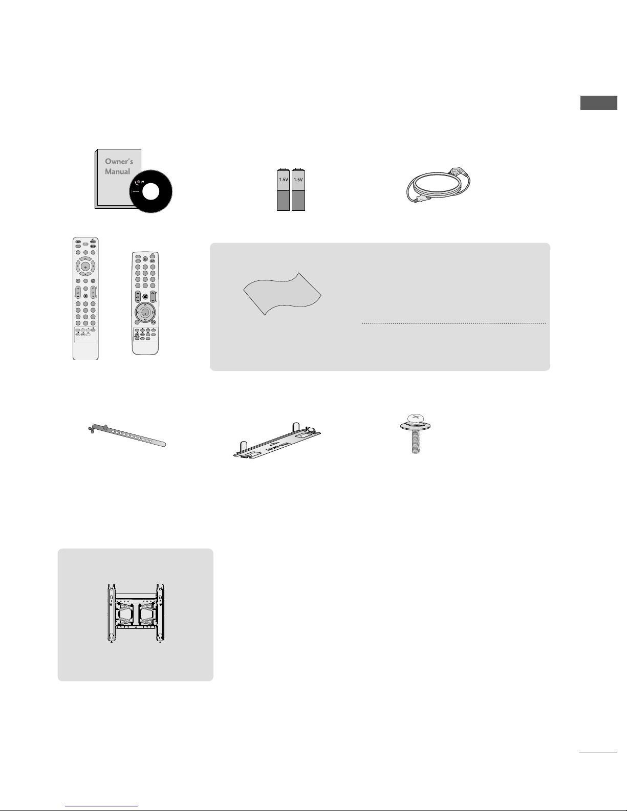
ACCESSORIES
ACCESSORIES
Ensure that the following accessories are included with your TV. If an accessory is missing, please contact the
dealer where you purchased the TV.
■
Image shown may differ from your TV
Owner’s Manual Batteries
Remote Control
Power Cord
Polishing Cloth
Polishing cloth for use on
the screen.
This item is not included for all models.
* Lightly wipe any stains or fingerprints on
the surface of the TV with the polishing
cloth.
Do not use excessive force. This may cause
scratching or discolouration.
FAV
MUTE
MARK
POWER
Q. MENU MENU
FREEZE
AV MODERETURN
OK
123
456
7809
Q. VIEW
LIST
P
A
G
E
RATIO
SLEEP
ENERGY SAVING
Protection cover
(Refer to p. 9)
Cable Holder
(Refer to P. 9)
Bolts for stand assembly
(Refer to P. 7)
x 4x 2
or
FAV
MARK
MENU
LIST
Q.VIEW
123
456
7809
MUTE
P
P
A
G
E
RETURN
INPUTRATIO
POWER
AV MODE
ENERGY SAVING
FREEZE
Q.MENU
OK
AW-50PG60MS
Wall Mounting Bracket
(Separate purchase)

CONTENTS
2
CONTENTS
PREPARATION
Front Panel Controls................................................. 4
Back Panel Information ............................................ 6
Stand Installation....................................................... 7
Careful installation advice.........................................8
Back Cover for Wire Arrangement......................... 9
Swivel Stand ................................................................9
Not using the desk-type stand................................9
Desktop Pedestal Installation.................................10
Wall Mount: Horizontal installation......................10
ANTENNA CONNECTION .....................................11
ACCESSORIES.......................................................1
PICTURE CONTROL
Picture Size (Aspect Ratio) Control........................64
Energy Saving.....................................................66
Preset picture settings
Picture Mode-Preset.................................................67
Auto Colour Tone Control
(Warm/Medium/Cool) .............................................68
Manual Picture Adjustment
Picture Mode-User option ......................................69
Picture Improvement Technology ............................70
Advanced - Black(Darkness) Level...........................71
Advanced - Film Mode ................................................72
Picture Reset..................................................................73
Image Sticking Minimization (ISM) Method .........74
Demo mode ...................................................................75
Mode setting..................................................................76
AV Mode .........................................................................47
key Lock......................................................................48
Initializing (Reset to original factory settings) ..49
EXTERNAL EQUIPMENT SETUP
HD Receiver Setup.................................................. 12
DVD Setup................................................................ 15
VCR Setup................................................................. 18
Other A/V Source Setup ........................................21
Usb in Setup............................................................. 21
PC Setup ................................................................... 22
- Screen Setup for PC Mode........................... 24
WATCHING TV / PROGRAMME CONTROL
REMOTE CONTROL KEY FUNCTIONS ................28
Turning on the TV ........................................................32
Programme Selection...................................................32
Volume Adjustment ................................................... 32
Quick Menu....................................................................33
On Screen Menus Selection and adjustment .......34
Auto programme tuning ............................................35
Manual programme Tuning ........................................36
Programme Edit ...........................................................38
SELECTING THE PROGRAMME TABLE .................40
Favourite programme setup........................................41
Input LIST .......................................................................42
SIMPLINK........................................................................43
Input LABEL....................................................................46
TO USE THE USB DEVICE
When connecting the USB device...........................50
Photo list.........................................................................51
Music list .........................................................................55
Movie list.........................................................................58
DivX Registration Code .............................................62
Deactivation ..................................................................63

CONTENTS
3
SOUND & LANGUAGE CONTROL
Auto Volume Leveler................................................77
Preset Sound Settings-Sound Mode....................78
Sound Setting Adjustment -User Mode..............79
SRS TruSurround XT................................................79
Clear Voice II.............................................................80
Balance........................................................................81
Audio Reset ...............................................................82
TV Speakers On/ Off Setup ..................................83
I/II
Stereo/Dual Reception.........................................84
NICAM Reception ................................................85
Speaker Sound Output Selection ......................85
On-Screen Menu Language /
Country Selection ........................................................................86
TELETEXT
Switch on/off ...........................................................90
SIMPLE Text...............................................................90
TOP Text.....................................................................90
FASTEXT.....................................................................91
Special Teletext Functions ......................................91
APPENDIX
Troubleshooting........................................................92
Maintenance..............................................................94
Product Specifications ............................................95
IR Codes .....................................................................97
External Control Device Setup..............................99
TIME SETTING
Clock Setup ...............................................................87
Auto on/off timer setting.......................................88
Sleep Timer setting..................................................89
PREPARATION
4
PREPARATION
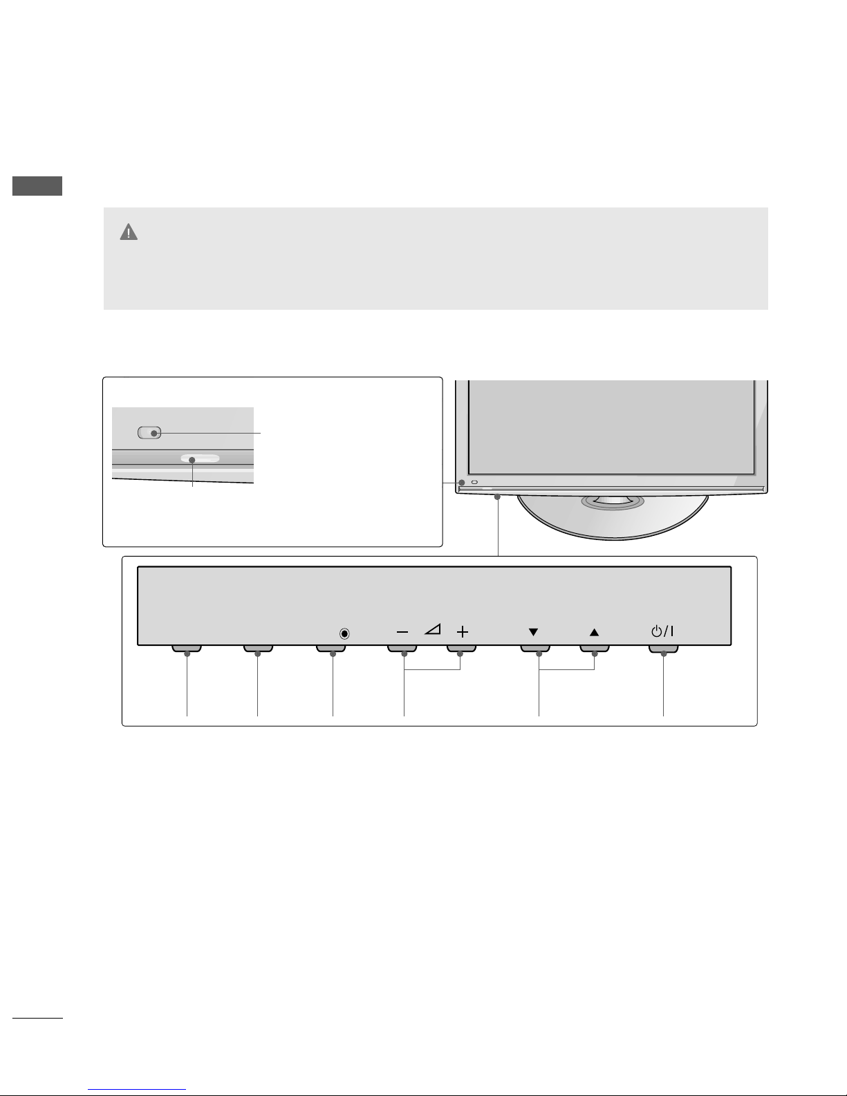
FRONT PANEL CONTROLS
■
Image shown may differ from your TV.
P
MENU
INPUT
OK
INPUT
POWER
MENU
OK
VOLUME PROGRAMME
42/50PQ2
***
Power/Standby Indicator
•
Illuminates red in standby mode.
•
Illuminates blue when the TV is switched on.
Intelligent Sensor
Adjusts picture according to the
surrounding conditions
Remote Control Sensor
GG
When the TV cannot be turned on with the remote control, press the main power button on the TV.
(When the power is turned off with the main power button on the TV, it will not be turned on with the
remote control.)
CAUTION
5
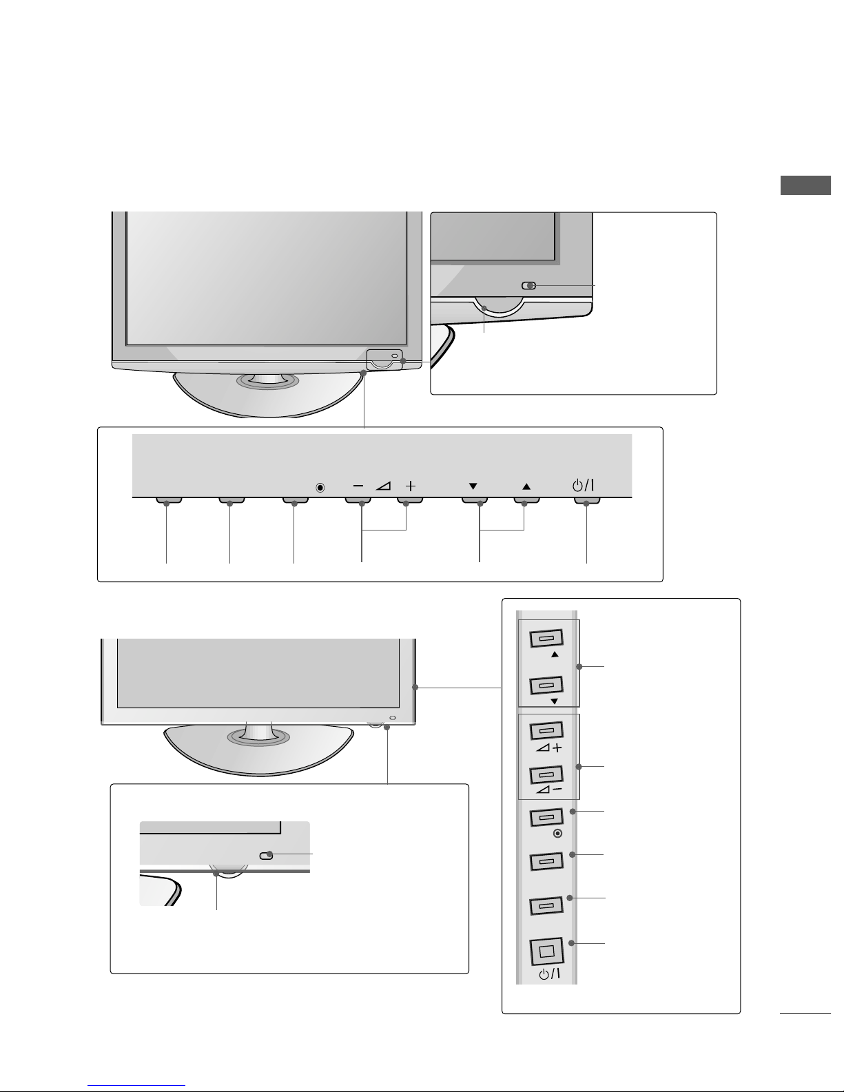
PREPARATION
PROGRAMMEVOLUMEMENU OK
INPUT
POWER
42/50PQ3
***
MENU
INPUT
OK
P
P
PROGRAMME
VOLUME
OK
MENU
INPUT
POWER
P
MENU
MENU
INPUT
INPUT
OK
OK
IInntteell ll iiggeenntt SSeennssoorr
Adjusts picture according to the surrounding
conditions.
RReemmoottee CCoonn ttrr ooll
SSeenn ssoorr
PPoowwee rr//SSttaann dd bb yy IInn dd ii ccaattoorr
•
Illuminates red in standby mode.
•
Illuminates blue when the TV is switched on.
Power/Standby Indicator
•
Illuminates red in standby mode.
• The LED is off while the TV remains on.
42/50PQ6
***
IInntteell ll iigg eenn tt SS ee nnss oo rr
Adjusts picture according to
the surrounding conditions.
RReemmoottee CCoonn tt rr oo ll SSeenn ssoo rr
PREPARATION
6
PREPARATION
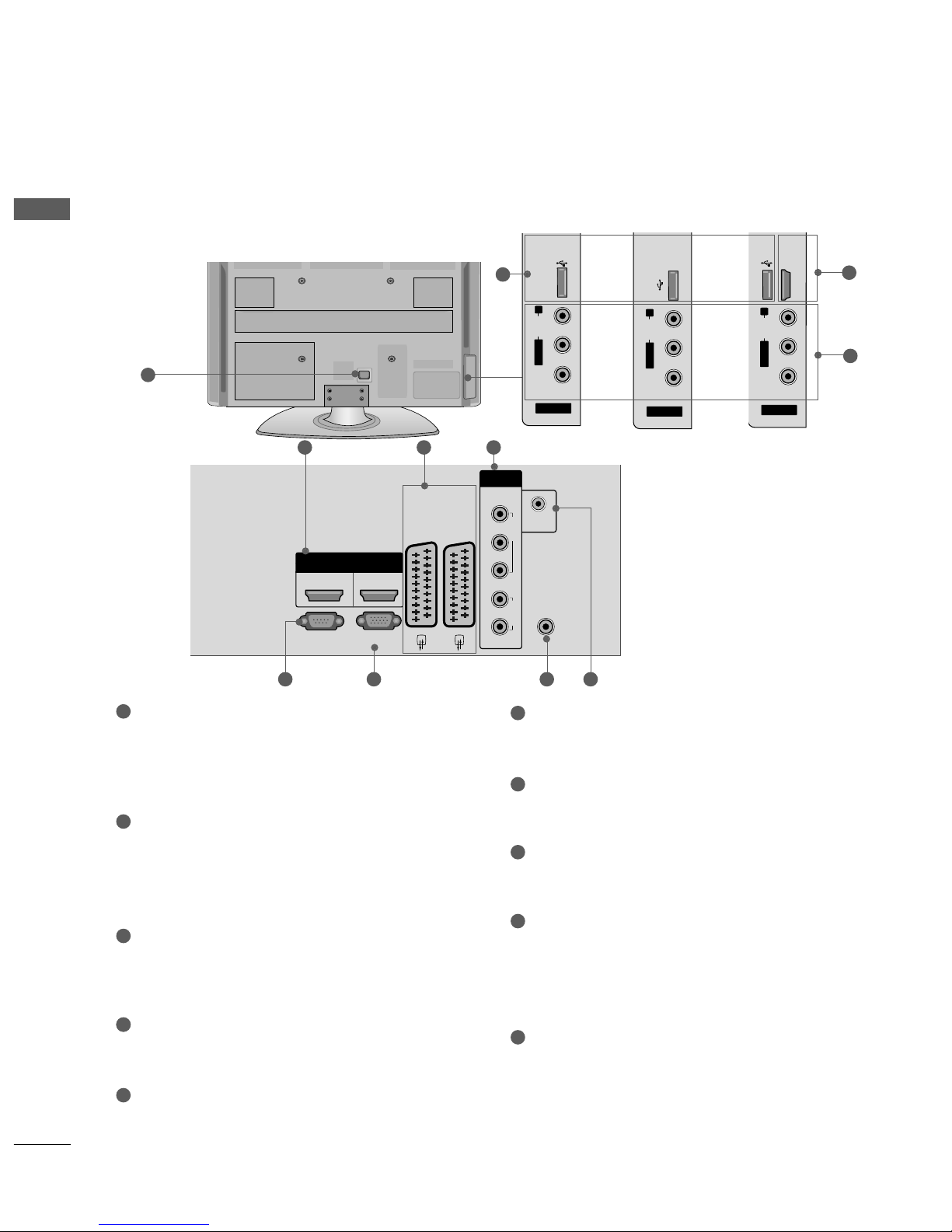
BACK PANEL INFORMATION
A
Image shown may differ from your TV.
Power Cord Socket
This TV operates on an AC power. The voltage is
indicated on the Specifications page. Never
attempt to operate the TV on DC power.
HDMI Input
Connect a HDMI signal to HDMI IN
Or DVI(VIDEO)signal to HDMI/DVI port with DVI
to HDMI cable.
Euro Scart Socket (AV1/AV2)
Connect scart socket input or output from an
external device to these jacks.
Component Input
Connect a component video/audio device to this jack.
RS-232C Input
(CONTROL&SERVICE) Port
Connect to the RS-232C port on a PC.
This port is used for Service or Hotel mode.
RGB Input
Connect the output from a PC.
Antenna Input
Connect RF antenna to this jack.
RGB/DVI Audio Input
Connect the audio from a PC or DTV.
USB Input
42/50PQ2
***
: Service only
42/50PQ3
***
: Used for Photo and Music
42/50PQ6
***
: Used for Photo, Music and Movie
Audio/Video Input(AV3)
Connect audio/video output from an external
device to these jacks.
1
6
7
8
9
10
2
3
44
5
R
R
R
ANTENNA
IN
R
R
R
RGB(PC)
R
L
Y
P
B
P
R
VIDEO
AUDIO
COMPONENT
HDMI
12
RS-232C IN
(CONTROL&SERVICE)
HDMI/DVI IN HDMI IN
AV 1V 1 AV 2V 2
IN
AUDIO IN
(RGB/DVI)
1
2 3
6 7 85
4
R
R
AV IN 3
L/ MONO
R
AUDIO
VIDEO
USB IN
SERVICE ONLY
AV IN 3
L/MONO
R
AUDIO
VIDEO
USB IN
R
AV IN 3
L/ MONO
R
AUDIO
VIDEO
USB IN
HDMI IN3
Only 42/50PQ2
***
Only 42/50PQ3
***
Only 42/50PQ6
***
10
2
9
7
PREPARATION
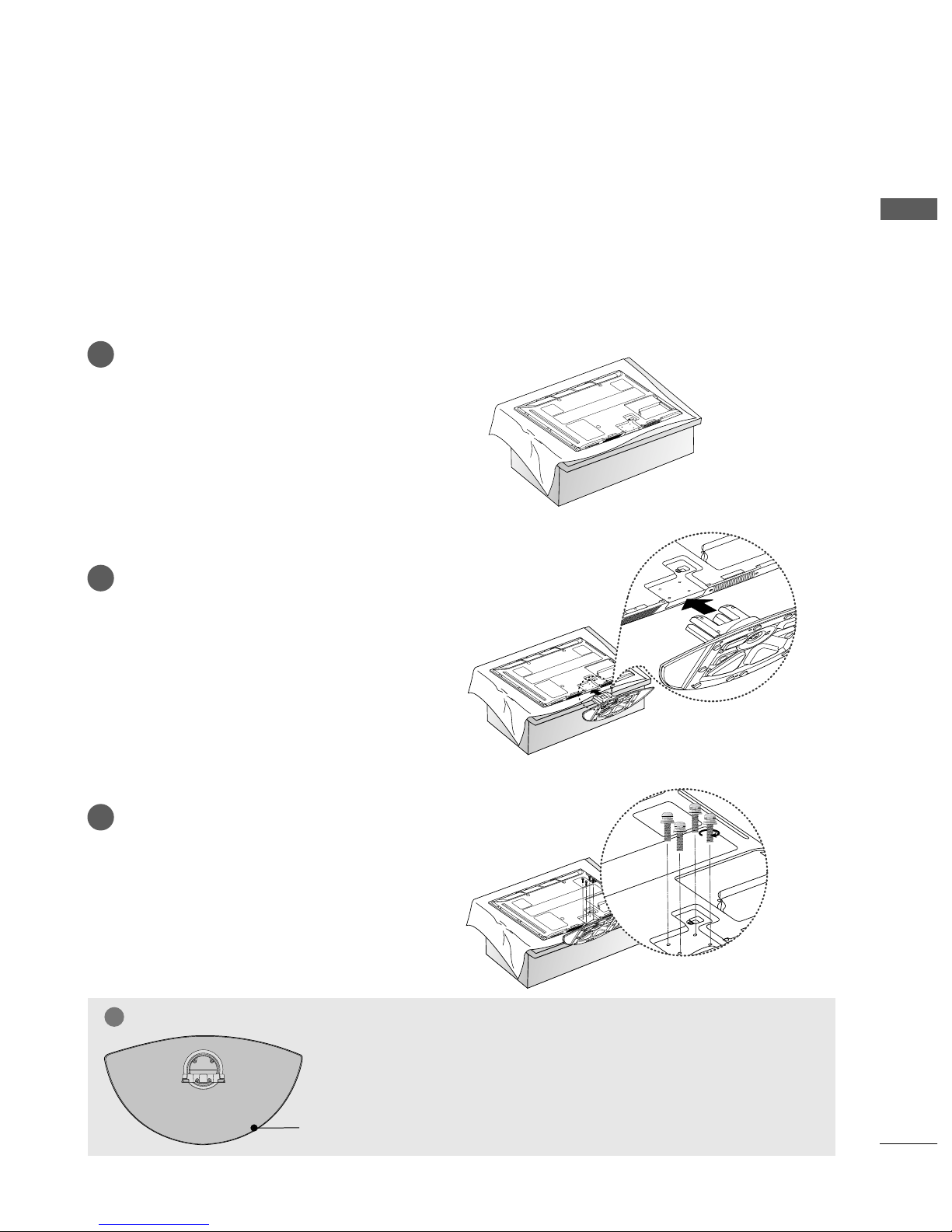
STAND INSTALLATION
■
Image shown may differ from your TV
■
When assembling the desk type stand, check whether the bolt is fully tightened. (If not tightened fully, thep
roduct can tilt forward after the product installation.) If you tighten the bolt with excessive force, the boltcan
deviate from abrasion of the tightening part of the bolt.
Carefully place the TV screen side down on a
cushioned surface to protect the screen from
damage.
Assemble the TV as shown.
Fix the 4 bolts securely using the holes in the
back of the TV.
1
2
3
GG
When assembling the stand, make sure to distinguish and assemble the
front and rear side of the stand correctly.
NOTE
!
FRONT
PREPARATION
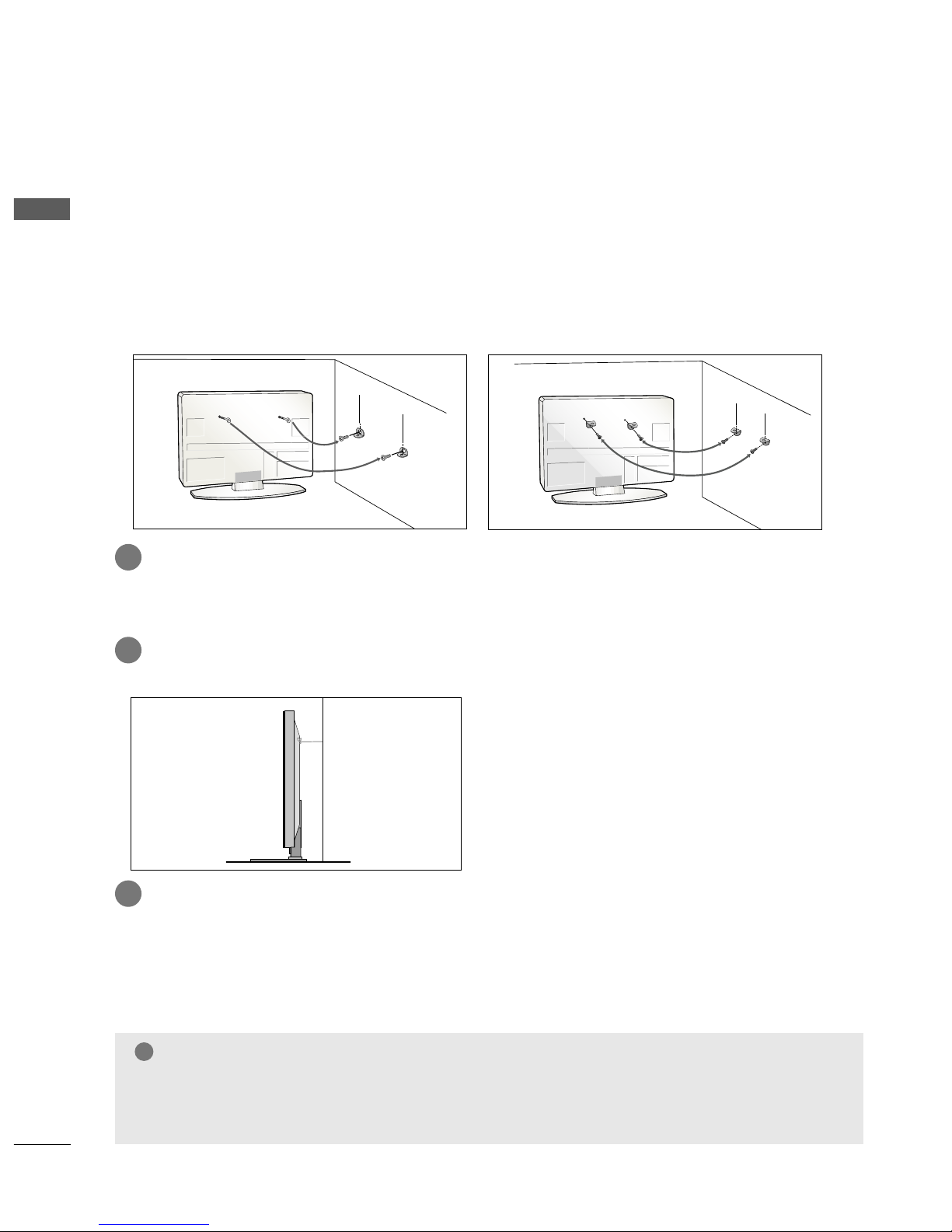
CAREFUL INSTALLATION ADVICE
8
PREPARATION
2
1
A
You should purchase necessary components to fix the TV safety and secure to the wall from the market.
A
Position the TV close to the wall to avoid the possibility of it falling when pushed.
A
The instructions shown below are a safer way to set up the TV, by fixing it to the wall, avoiding the possibility
of it falling forwards if pulled. This will prevent the TV from falling forward and causing injury. This will
also prevent the TV from damage. Ensure that children do not climb or hang from the TV.
NOTE
!
G
When moving the TV undo the cords first.
G
Use a platform or cabinet strong and large enough to support the size and weight of the TV.
G
To use the TV safely make sure that the height of the bracket on the wall and on the TV is the same.
2
3
1
1
2
Use the eye-bolts or TV brackets/bolts to fix the product to the wall as shown in the picture.
(If your TV has bolts in the eyebolts, loosen then bolts.)
* Insert the eye-bolts or TV brackets/bolts and tighten them securely in the upper holes.
Secure the wall brackets with the bolts on the wall. Match the height of the bracket that is mounted on the
wall.
3
Use a sturdy rope to tie the product for alignment. It is safer to tie the rope so it becomes horizontal between the wall and the product.
PREPARATION
9
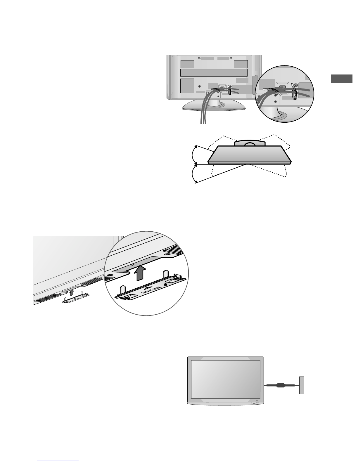
SWIVEL STAND
This feature is not available for all models.
After installing the TV, you can adjust the TV set manually to the left or right direction by 20 degrees to
suit your viewing position.
■
Here shown may differ from your TV.
When installing the wall-mounted unit, use the protection cover. Insert the
PPRROOTTEECCTTIIOONN CCOOVVEERR
into the TV
until clicking sound.
NOT USING THE DESK-TYPE STAND
Protection cover
Power Supply
Circuit breaker
EARTHING
Ensure that you connect the earth wire to prevent possible
electric shock. If grounding methods are not possible, have a
qualified electrician install a separate circuit breaker.
Do not try to earth the TV by connecting it to telephone
wires, lightening rods or gas pipes.
BACK COVER FOR WIRE ARRANGEMENT
■
Image shown may differ from your TV.
After Connecting the cables as necessary, install
CABLE HOLDER as shown and bundle the
cables.
CABLE HOLDER
PREPARATION
10
PREPARATION
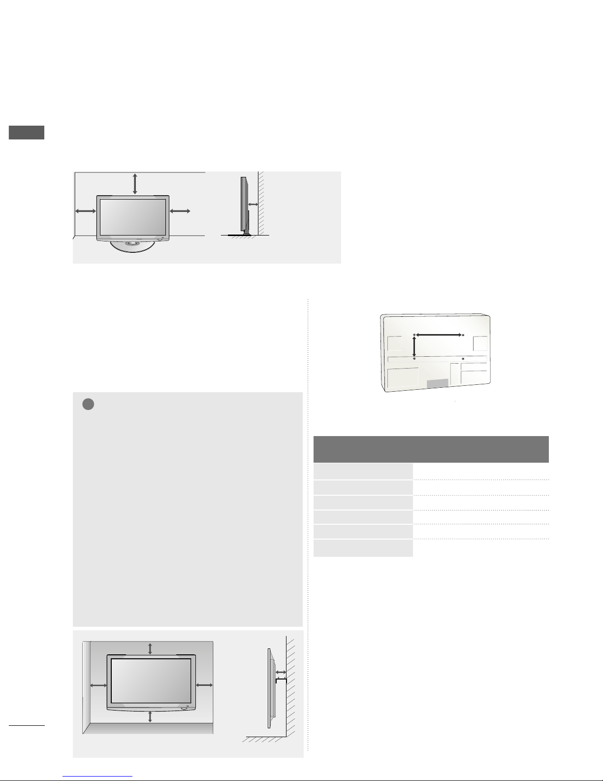
WALL MOUNT: HORIZONTAL INSTALLATION
A
We recommend the use of a LG Brand wall mounting
bracket when mounting the TV to a wall.
A
We recommend that you purchase a wall mounting
bracket which supports VESA standard.
A
LG recommends that wall mounting be performed
by a qualified professional installer.
44 ii nncchh eess 44 ii nncchh eess
44 ii nncchh eess
44 ii nncchh eess
44 ii nncchh eess
NOTE
!
G Should Install wall mount on a solid wall perpen-
dicular to the floor.
G Should use a special wall mount, if you want to
install it to ceiling or slanted wall.
G The surface that wall mount is to be mounted on
should be of sufficient strength to support the
weight of TV set; e.g. concrete, natural rock, brick
and hollow block.
G Installing screw type and length depends on the wall
mount used. Further information, refer to the
instructions included with the mount.
G LG is not liable for any accidents or damage to
property or TV due to incorrect installation:
- Where a non-compliant VESA wall mount is used.
- Incorrect fastening of screws to surface which may
cause TV to fall and cause personal injury.
- Not following the recommended Installation
method.
44 ii nncchh eess 44 ii nncchh eess
44 ii nncchh eess
44 ii nncchh eess
DESKTOP PEDESTAL INSTALLATION
For adequate ventilation allow a clearance of 4” (10cm) all around the TV.
AA
BB
Model
VESA
(A *B)
Standard
Screw
Quantity
42PQ2
***
50PQ2
***
42PQ3
***
50PQ3
***
42PQ6
***
50PQ6
***
400 * 400
400 * 400
400 * 400
400 * 400
400 * 400
400 * 400
M6
M6
M6
M6
M6
M6
4
4
4
4
4
4
A
The TV can be installed in various ways such as on a wall, or on a desktop etc.
A
The TV is designed to be mounted horizontally.
ANTENNA
IN
R
R
R
11
PREPARATION
ANTENNA
IN
R
R
R
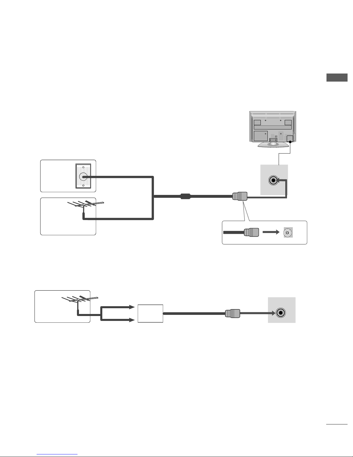
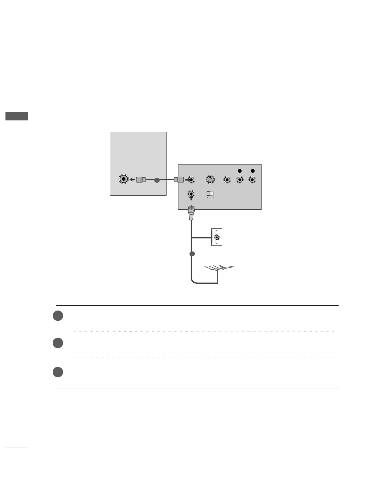
ANTENNA CONNECTION
R
■
For optimum picture quality, adjust antenna direction.
■
An antenna cable and converter are not supplied.
■
To prevent damage do not connect to the mains outlet until all connections are made between the devices.
Multi-family Dwellings/Apartments
(Connect to wall antenna socket)
Single-family Dwellings /Houses
(Connect to wall jack for outdoor antenna)
Outdoor
Antenna
(VHF, UHF)
Wall
Antenna
Socket
RF Coaxial Wire (75 ohm)
Antenna
UHF
Signal
Amplifier
VHF
■
In poor signal areas, to achieve better picture quality it may be necessary to install a signal amplifier to the
antenna as shown above.
■
If signal needs to be split for two TVs,use an antenna signal splitter for connection.
12
EXTERNAL EQUIPMENT SETUP
EXTERNAL EQUIPMENT SETUP
■
To avoid damaging any equipment, never plug in any power cords until you have finished connecting all equipment.
■
Image shown may differ from your TV.
ANTENNA
IN
R
L
Y
P
B
P
R
VIDEO
AUDIO
COMPONENT
IN
AUDIO IN
(RGB/DVI)
1
2
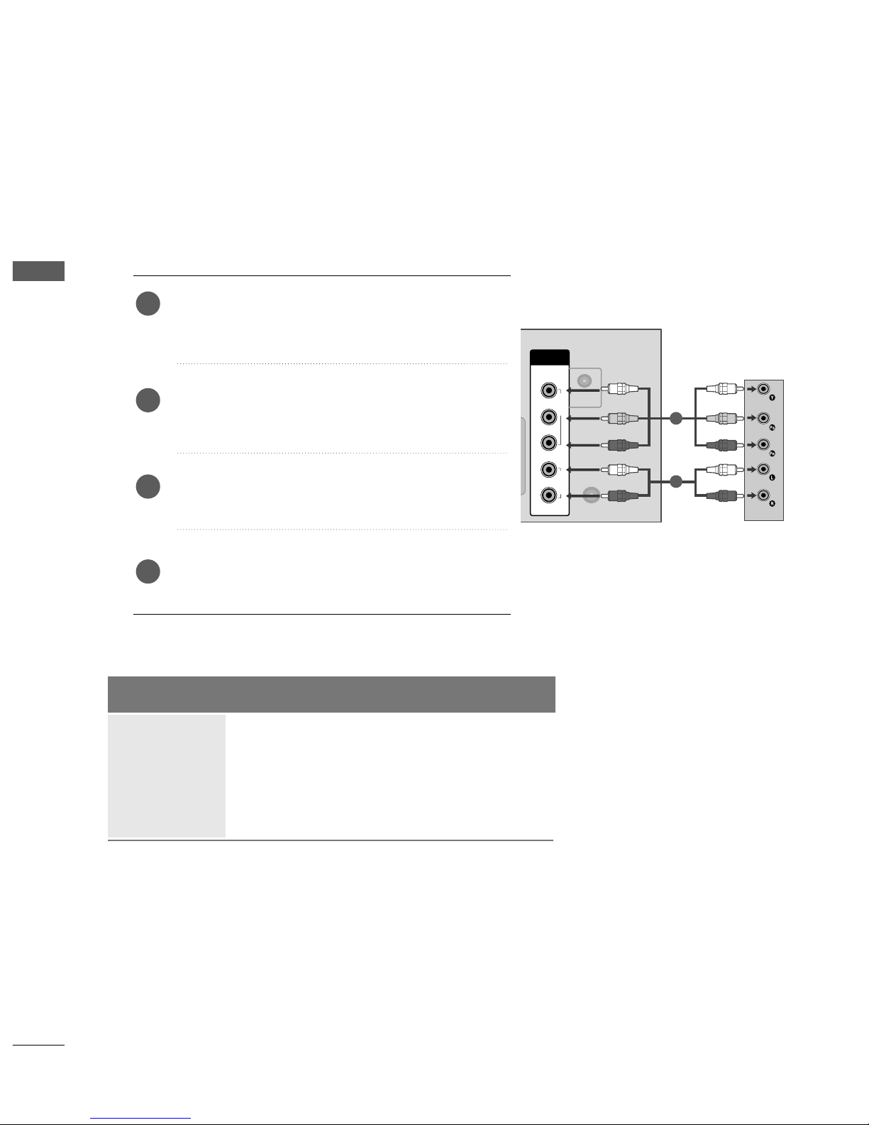
HD RECEIVER SETUP
Connecting with a component cable
Connect the video outputs (Y, PB
, PR
)
of the digital set-
top box to the
CC OOMMPPOONN EENNTT II NN VV IIDDEEOO
jacks on the
TV.
Connect the audio output of the digital set-top box to
the
CC OOMMPPOONN EENNTT II NN AA UUDDIIOO
jacks on the TV.
Turn on the digital set-top box.
(
Refer to the owner’s manual for the digital set-top box.
)
Select
CC oo mm pp oo nneenntt
input source using the
II NN PPUUTT
button on the remote control.
2
3
4
1
Signal
480i/576i
480p/576p
720p/1080i
10 8 0 p
Component
O
O
O
O
(Only 50Hz, 60Hz)
HDMI
X
O
O
O
(24Hz, 30Hz, 50Hz, 60Hz)
13
EXTERNAL EQUIPMENT SETUP
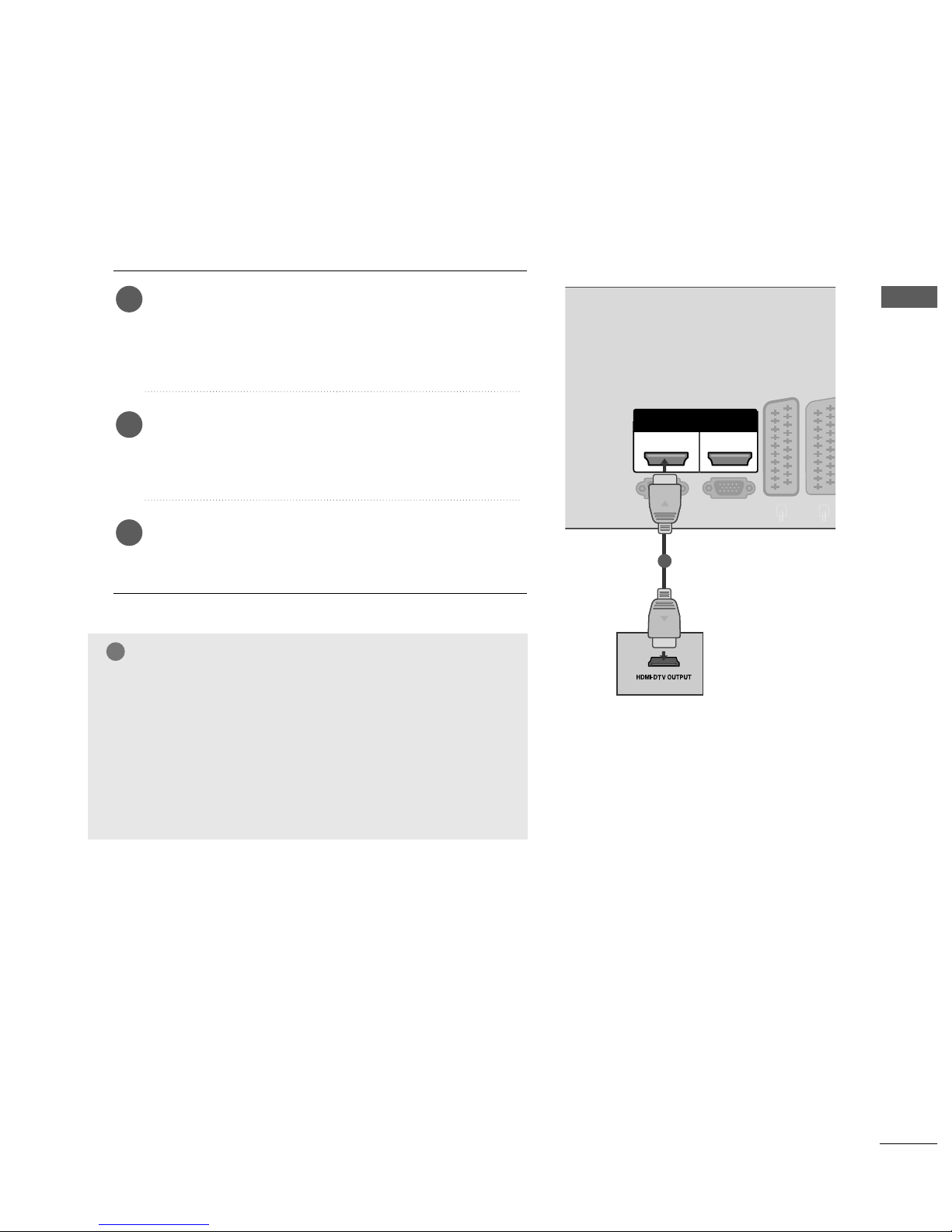
Connecting a set-top box with an HDMI cable
Connect the HDMI output of the digital set-top box to
the
HHDD MMII//DDVV II II NN 11,, HHDDMMII IINN 22orHHDD MMII II NN
33
(Except 42/50PQ2
***
, 42/50PQ3
***) models
jack
on the TV.
Select
HH DD MMII11,, HH DD MMII22
or
HH DD MMII33
(Except
42/50PQ2
***
, 42/50PQ3
***
) input source using the
II NN PPUUTT
button on the remote control.
Turn on the digital set-top box.
(
Refer to the owner’s manual for the digital set-top box.
)
2
3
1
R
AV 1V 1 AV 2V 2
RGB(PC)
RS-232C IN
(CONTROL
&SERVICE
)
HDMI
12
HDMI/DVI IN HDMI IN
1
GG
Check your HDMI cable is over version 1.3.
If the HDMI cables don’t support HDMI version 1.3, it can
cause flickers or no screen display. In this case use the latest
cables that support HDMI version 1.3.
GG
HDMI mode supports PCM audio format only.
GG
Audio format was reseted to Dolby/DTS/Bitstrem in DVD
Player or STB, it should be changed to PCM.
NOTE
!
14
EXTERNAL EQUIPMENT SETUP
EXTERNAL EQUIPMENT SETUP
AV 1 AV 2
AV 1V 1 AV 2V 2
ANTENNA
IN
RGB(PC)
R
L
Y
P
B
P
R
VIDEO
AUDIO
COMPONENT
RS-232C IN
(CONTROL
&SERVICE
)
IN
HDMI
12
HDMI/DVI IN HDMI IN
AUDIO IN
(RGB/DVI)
1
2
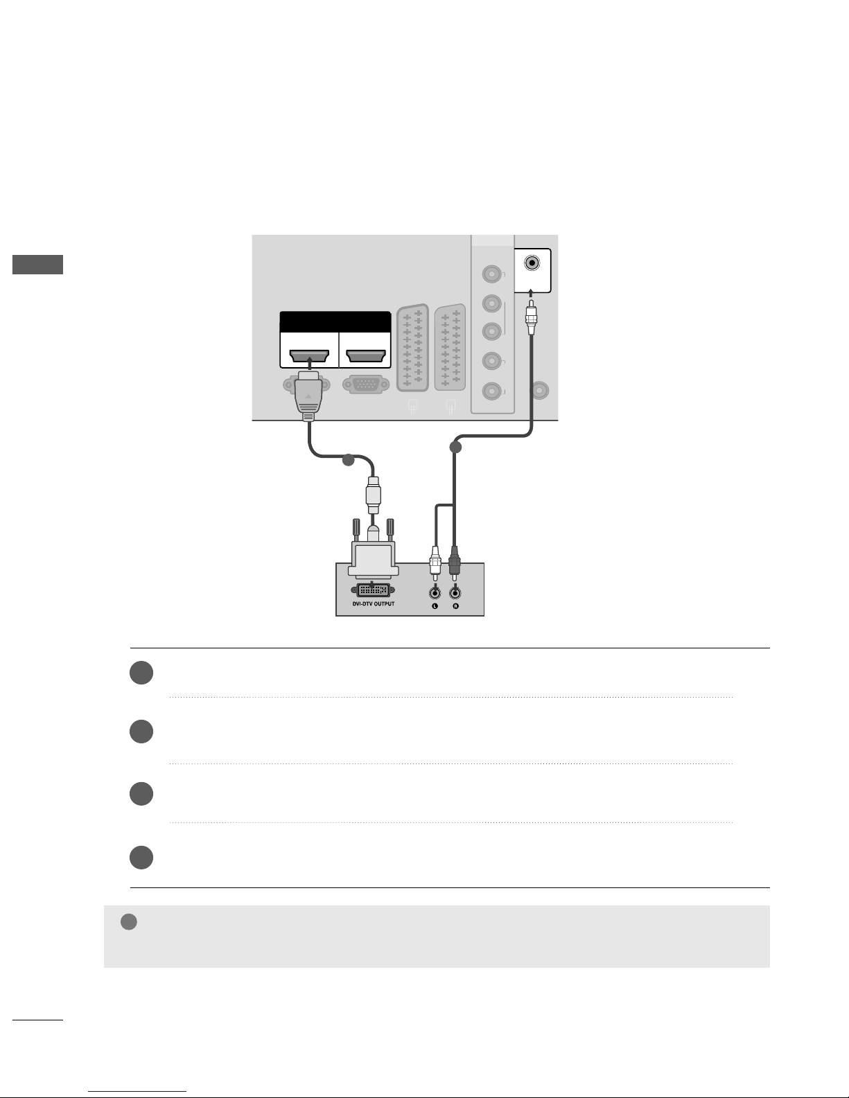
Connect the DVI output of the digital set-top box to the
HHDD MMII//DD VVII IINN 11
jack on the TV.
Connect the audio output of the digital set-top box to the
AAUU DDIIOO IINN((RRGG BB//DDVV II ))
jack on the TV.
Turn on the digital set-top box. (Refer to the owner’s manual for the digital set-top box.
)
Select
HH DD MMII11
input source using the
II NN PPUUTT
button on the remote control.
2
3
4
1
Connecting with a HDMI to DVI cable
GG
Audio format was reseted to Dolby/DTS/Bitstrem in DVD Player or STB, it should be changed to PCM.
NOTE
!
15
EXTERNAL EQUIPMENT SETUP
DVD SETUP
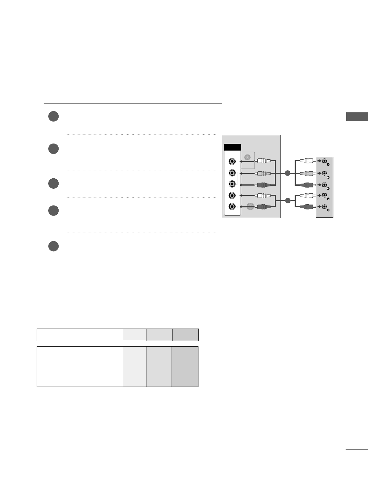
Connecting with a component cable
Component Input ports
To achieve better picture quality, connect a DVD player
to the component input ports as shown below.
Component ports on the TV
YPB PR
Video output ports
on DVD player
Y
Y
Y
Y
PB
B-Y
Cb
Pb
PR
R-Y
Cr
Pr
Connect the video outputs (Y, P
B, PR
)
of the DVD to the
CC OOMMPPOONN EENNTT II NN VV II DDEEOO
jacks on the TV.
Connect the audio outputs of the DVD to the
CC OOMMPPOONN EENNTT II NN AA UUDD IIOO
jacks on the TV.
Turn on the DVD player, insert a DVD.
Select
CC oo mm pp oo nneenn tt
input source using the
II NNPPUUTT
button on
the remote control.
Refer to the DVD player's manual for operating instructions.
2
3
4
5
1
ANTENNA
IN
R
L
Y
P
B
P
R
VIDEO
AUDIO
COMPONENT
IN
AUDIO IN
(RGB/DVI)
1
2
16
EXTERNAL EQIPMENT SETUP
EXTERNAL EQUIPMENT SETUP
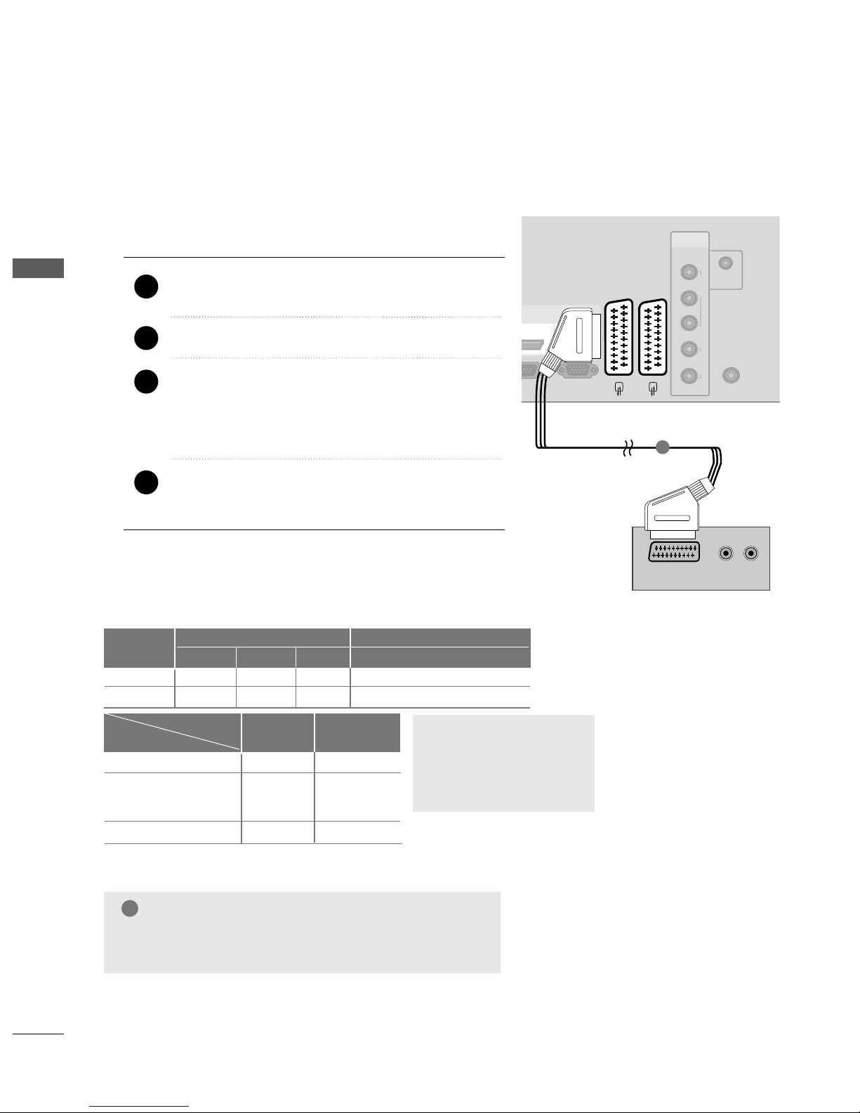
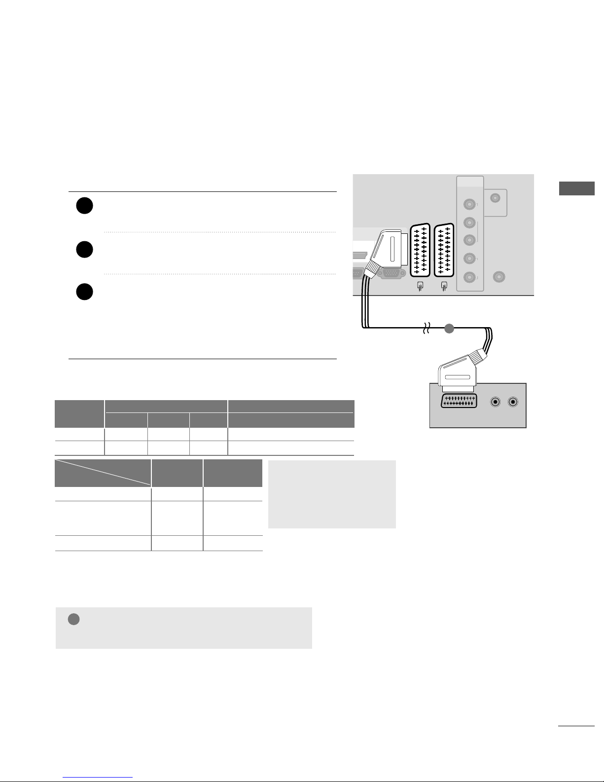
When connecting with a Euro Scart
Connect the Euro scart socket of the DVD to the
AAVV 11
Euro scart socket on the set.
Turn on the DVD player, insert a DVD.
Select
AAVV 11
input source with using the
II NNPP UUTT
button
on the remote control.
If connected to
AAVV 22
Euro scart socket, select
AAVV 22
input source.
Refer to the DVD player's manual for operating
instructions.
2
3
4
1
ANTENNA
IN
RGB(PC)
R
L
Y
P
B
P
R
VIDEO
AUDIO
COMPONENT
32C IN
IN
AUDIO IN
(RGB/DVI)
HDMI
12
AV 1 AV 2
(R) AUDIO (L)
AUDIO/
VIDEO
1
NOTE
!
GG
Any Euro scart cable used must be signal shielded.
Scart
AV1
AV2
Input
Video Audio RGB
Output
Video, Audio
ATV only
ATV output is available.
OOO
OOX
Analogue TV
AV1/2/3
Component/RGB/HDMI
AV1
(TV Out)
OO
OO
OX
AV2
(Monitor Out)
GG
TV Out : Outputs analog
TV signals.
Monitor Out: Outputs the
current screen image.
Output Type
Current
input mode
17
EXTERNAL EQUIPMENT SETUP
AV 1 AV 2
AV 1 AV 2
RGB(PC)
RS-232C IN
(CONTROL&SERVICE)
HDMI
12
HDMI/DVI IN HDMI IN
1
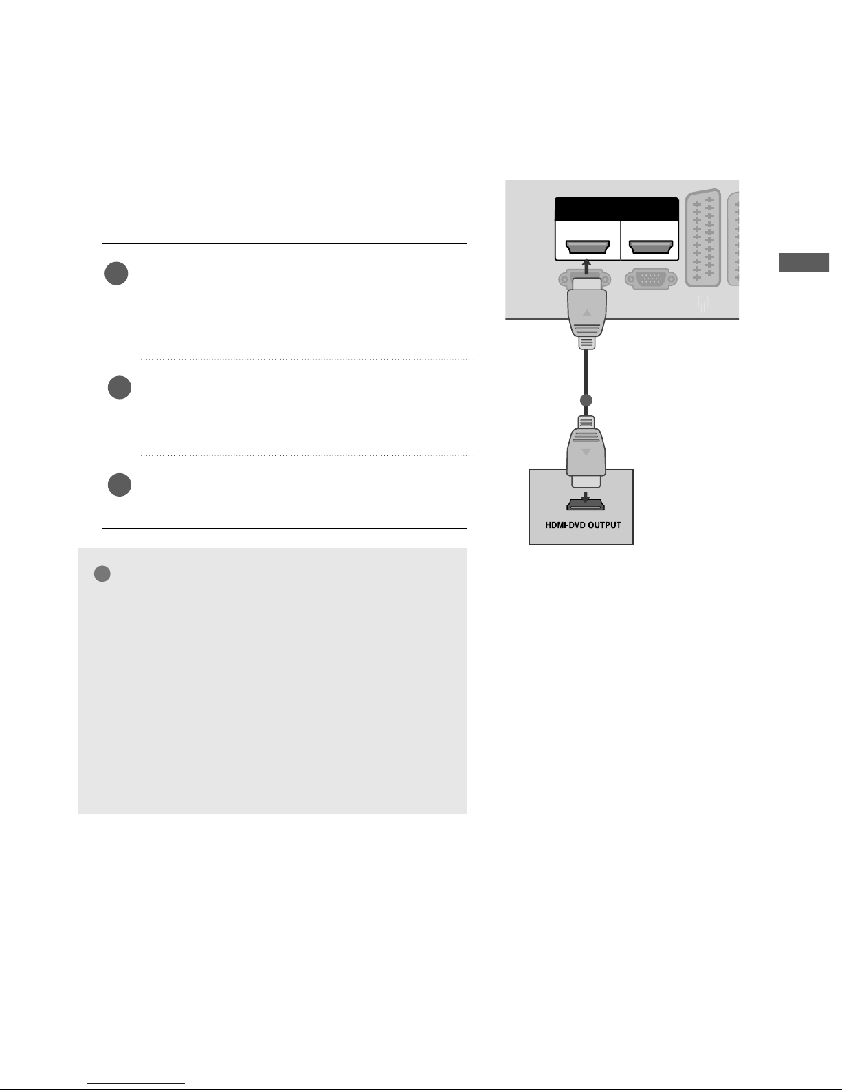
Connecting the HDMI cable
Connect the HDMI output of the DVD to the
HHDD MMII//DDVV II II NN 11,, HHDDMMII IINN 22orHHDD MMII II NN
33
(Except 42/50PQ2
***
, 42/50PQ3
***
) jack on the
TV.
Select
HH DD MMII11,, HH DD MMII22
or
HH DD MMII33
(Except
42/50PQ2
***
, 42/50PQ3
***
) input source using
the
II NN PPUUTT
button on the remote control.
Refer to the DVD player's manual for operating
instructions.
1
2
3
GG
The TV can receive video and audio signals simultaneously
when using a HDMI cable.
GG
If the DVD does not support Auto HDMI, you must set the
output resolution appropriately.
GG
Check HDMI cable over version 1.3.
If the HDMI cables don’t support HDMI version 1.3, it can
cause flickers or no screen display. In this case use the latest
cables that support HDMI version 1.3.
GG
HDMI mode supports PCM audio format only.
GG
Audio format was reseted to Dolby/DTS/Bitstrem in DVD
Player or STB, it should be changed to PCM.
NOTE
!
18
EXTERNAL EQIPMENT SETUP
EXTERNAL EQUIPMENT SETUP
ANTENNA
IN
OUTPUT
SWITCH
ANT IN
R
S-VIDEO VIDEO
ANT OUT
L
Wall Jack
Antenna
VCR SETUP
Connecting with a RF cable
■
To avoid picture noise (interference), allow adequate distance between the VCR and TV.
Connect the
AANNTT OO UU TT
socket of the VCR to the
AANNTT EENN NNAA II NN
socket on the TV.
Connect the antenna cable to the
AANNTT IINN
socket of the VCR.
Press the
PPLL AA YY
button on the VCR and match the appropriate programme between the TV and VCR for
viewing.
1
2
2
3
1
19
EXTERNAL EQUIPMENT SETUP
When connecting with a Euro Scart
Connect the Euro scart socket of the VCR to the
AAVV 11
Euro scart socket on the set.
Insert a video tape into the VCR and press PLAY on
the VCR. (Refer to the VCR owner’s manual.)
Select
AAVV 11
input source with using the
II NNPP UUTT
button on the remote control.
If connected to
AAVV 22
Euro scart socket, select
AAVV 22
input source.
2
3
1
NOTE
!
GG
Any Euro scart cable used must be signal shielded.
ANTENNA
IN
RGB(PC)
R
L
Y
P
B
P
R
VIDEO
AUDIO
COMPONENT
&SERVICE)
IN
AUDIO IN
(RGB/DVI)
HDMI
12
AV 1 AV 2
(R) AUDIO (L)
AUDIO/
VIDEO
1
Scart
AV1
AV2
Input
Video Audio RGB
Output
Video, Audio
ATV only
ATV output is available.
OOO
OOX
Analogue TV
AV1/2/3
Component/RGB/HDMI
AV1
(TV Out)
OO
OO
OX
AV2
(Monitor Out)
GG
TV Out : Outputs analog
TV signals.
Monitor Out: Outputs the
current screen image.
Output Type
Current
input mode
20
EXTERNAL EQUIPMENT SETUP
EXTERNAL EQUIPMENT SETUP
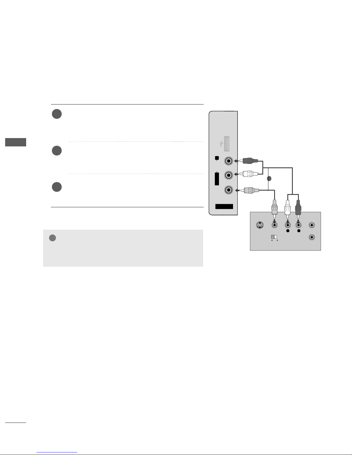
When connecting with a RCA cable
AV IN 3
L/ MONO
R
AUDIO
VIDEO
L
R
S-VIDEO
VIDEO
OUTPUT
SWITCH
ANT IN
ANT OUT
USB IN
Connect the
AAUU DD II OO/VVIIDD EEOO
jacks between TV and
VCR. Match the jack colours (Video = yellow, Audio Left
= white, and Audio Right = red)
Insert a video tape into the VCR and press PLAY on
the VCR. (Refer to the VCR owner’s manual.
)
Select
AAVV 33
input source using the
II NNPP UUTT
button on
the remote control.
1
2
3
GG
If you have a mono VCR, connect the audio cable from the
VCR to the
AAUU DDIIOO LL //MMOONN OO
jack of the set.
NOTE
!
1
21
EXTERNAL EQUIPMENT SETUP
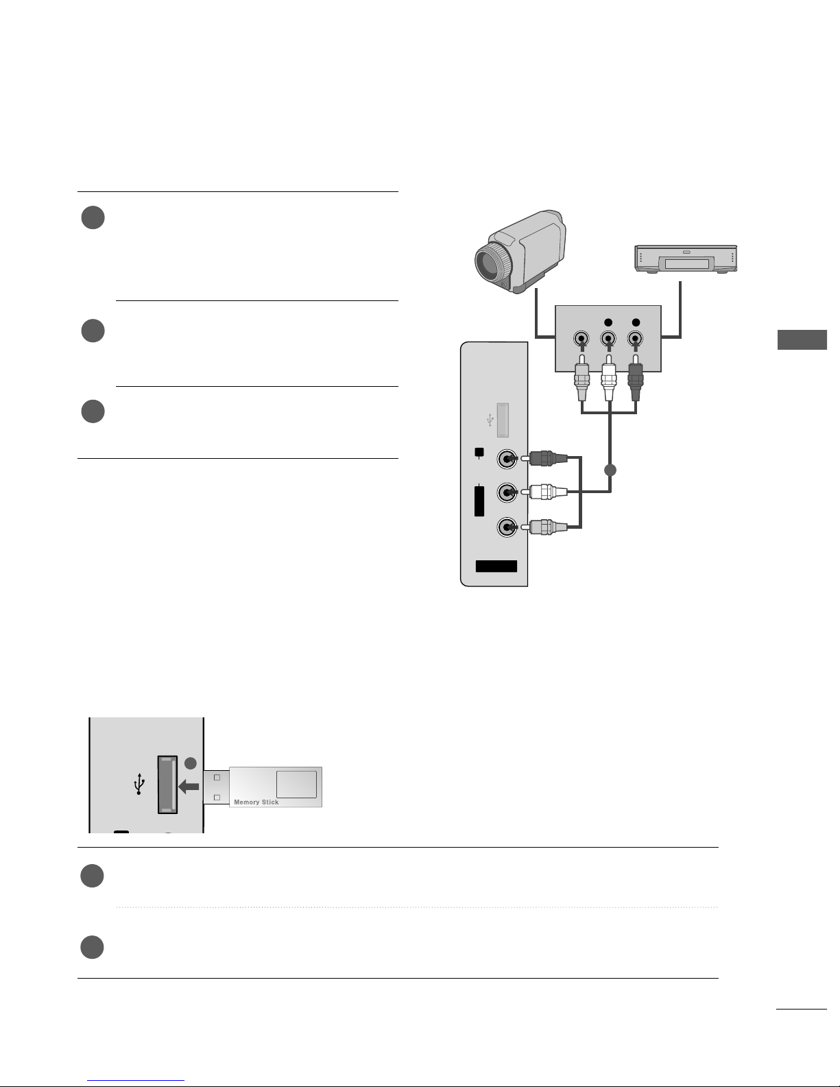
USB IN SETUP
(Except 42/50PQ2
***
)
■
Image shown may differ from your TV.
USB IN
Connect the USB device to the
UUSS BB IINN
jacks on the side of TV.
After connecting the
UUSS BB IINN
jacks, you use the
UU SSBB
function. (
GG
pp .. 5500
)
2
1
1
OTHER A/V SOURCE SETUP
Connect the
AAUU DDIIOO/VVIIDDEEOO
jacks between TV
and external equipment. Match the jack colours
.
(
Video = yellow, Audio Left = white, and Audio Right
= red
)
Select
AAVV 33
input source using the
II NN PPUUTT
button
on the remote control.
Operate the corresponding external equipment.
Refer to external equipment operating guide.
1
2
3
AV IN 3
L/MONO
R
AUDIO
VIDEO
USB IN
L R
VIDEO
Camcorder
Video Game Set
1
22
EXTERNAL EQIPMENT SETUP
EXTERNAL EQUIPMENT SETUP
AV 1
V 1
AV 2
ANTENNA
IN
R
L
Y
P
B
P
R
VIDEO
AUDIO
COMPONENT
RS-232C IN
(CONTROL&SERVICE)
IN
AUDIO IN
(RGB/DVI)
RGB OUTPUT
AUDIO
RGB(PC)
HDMI
12
HDMI/DVI IN HDMI IN
1
2
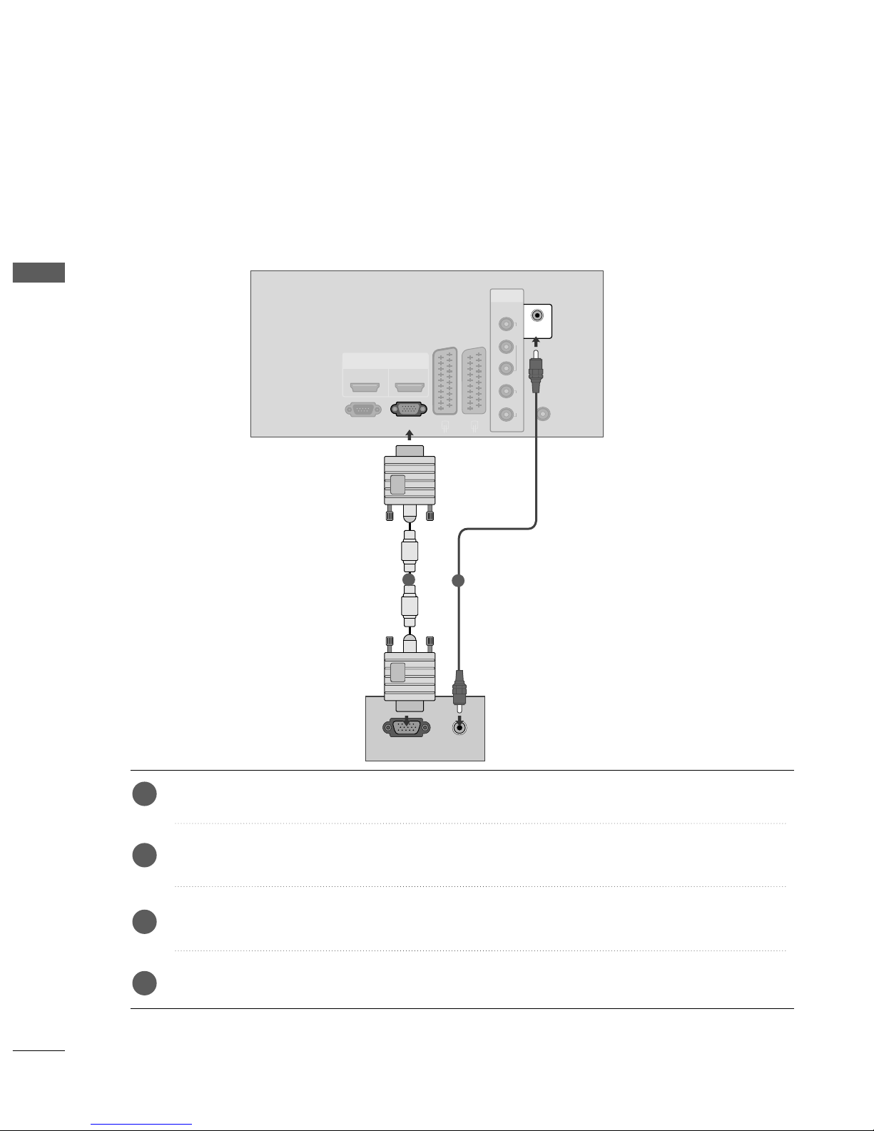
PC SETUP
This TV provides Plug and Play capability, meaning that the PC adjusts automatically to the TV's settings.
Connecting with a D-sub 15 pin cable
Connect the RGB output of the PC to the
RRGGBB ((PP CC
))
jack on the TV.
Connect the PC audio output to the
AAUUDDIIOO II NN (( RRGG BB//DDVVII ))
jack on the TV.
Turn on the TV and the PC.
Select
RRGGBB
input source using the
IINN PPUUTT
button on the remote control.
2
3
4
1
23
EXTERNAL EQUIPMENT SETUP
Supported Display Resolution
31.468 70.09
31.469 70.09
31.469 59.94
37.879 60.317
48.363 60.004
47.776 59.87
47.720 59. 799
Resolution
RGB-PC mode
Horizontal Vertical
Frequency(kHz) Frequency(Hz)
640x350
720x400
640x480
800x600
1024x768
1280x768
1360x768
Except 42PQ2
***
, 42PQ3
***
, 42PQ6
***
31.47 59.94
31.50 60.00
31.25 50.00
44.96 59.94
45.00 60.00
37.50 50.00
33.72 59.94
33.75 60.00
28.125 50.00
67.432 59. 94
67.5 60
56.250 50
27 24
33.75 30
Resolution
HDMI-DTV mode
Horizontal Vertical
Frequency(kHz) Frequency(Hz)
720x480
720x576
1280x720
1920x1080
NOTE
!
GG
Avoid keeping a fixed image on the TV ’s screen
for prolonged periods of time.The fixed image
may become permanently imprinted on the
screen;use a screen saver when possible.
GG
There may be interference relating to resolution,
vertical pattern, contrast or brightness in PC
mode. Change the PC mode to another resolution or change the refresh rate to another rate or
adjust the brightness and contrast on the menu
until the picture is clear. If the refresh rate of the
PC graphic card can not be changed, change the
PC graphic card or consult the manufacturer of
the PC graphic card.
GG
The synchronization input waveform for
Horizontal and Vertical frequencies are separate.
GG
We recommend using 1024 x 768, 60Hz
(42PQ2
***
, 42PQ3
***
, 42PQ6
***
XGA)/1360 x
768, 60Hz(50PQ2
***
, 50PQ3
***
, 50PQ6
***
WXGA) for the PC mode, this should provide
the best picture quality.
GG
If the resolution of PC is over SXGA, there will be
no picture on the TV.(Only HD Models)
GG
Connect the audio cable from the PC to the
Audio input on the TV.(Audio cables are not
included with the TV).
GG
If you use too long an RGB-PC cable, there may
be interference on the screen. We recommend
using under 5m of the cable. This provides the
best picture quality.
24
EXTERNAL EQIPMENT SETUP
EXTERNAL EQUIPMENT SETUP
1
MENU
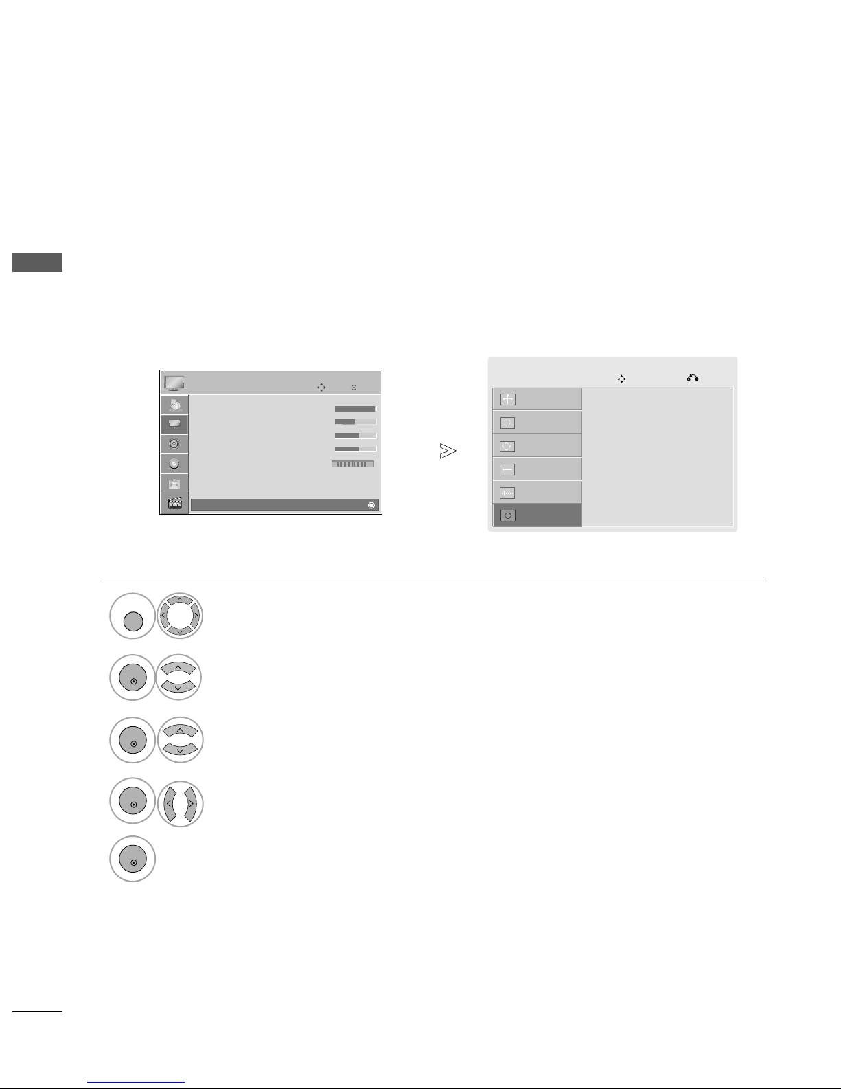
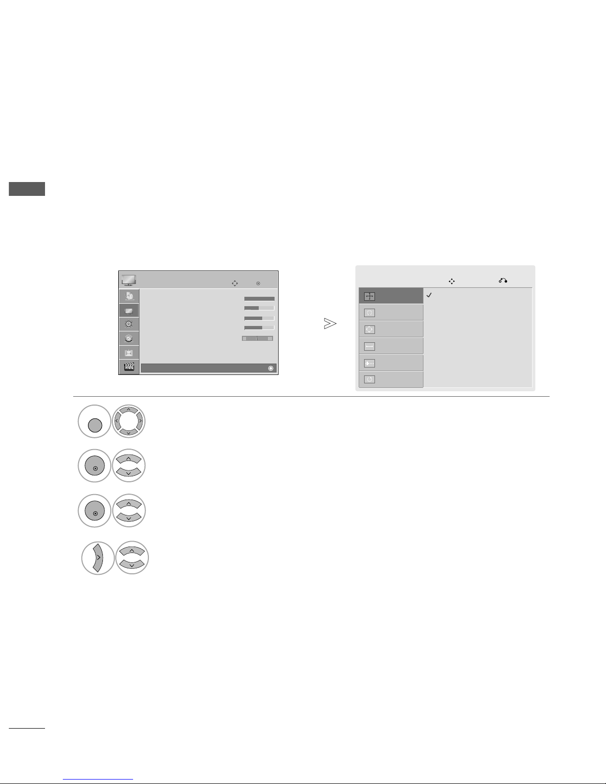
Screen Setup for PC mode
Returns Position, Size and Phase to the factory default settings.
This function works in the following mode: Component(except 480i, 576i), RGB
Screen Reset
Select
PPIICC TTUURREE
.
Select
SScc rr ee ee nn
.
3
Select
RRee ss ee tt
.
OK
Move
• Contrast 100
• Brightness 50
• Sharpness 70
• Colour 70
• Tint 0
• Advanced Control
• Picture Reset
Screen
PICTURE
E
Screen
2
OK
OK
RG
• Press the
MMEENN UU
button to return to normal TV viewing.
• Press the
RR EETTUURRNN
button to move to the previous menu screen.
Select
YYee ss
.
Run
RRee ss ee tt
.
4
OK
5
OK
To Set
Auto Config.
Screen
Move
Prev.
Resolution
Position
Size
Phase
Reset
G
25
EXTERNAL EQUIPMENT SETUP
Auto Config.
Screen
Move
Prev.
Resolution
Position
G
Size
Phase
Reset
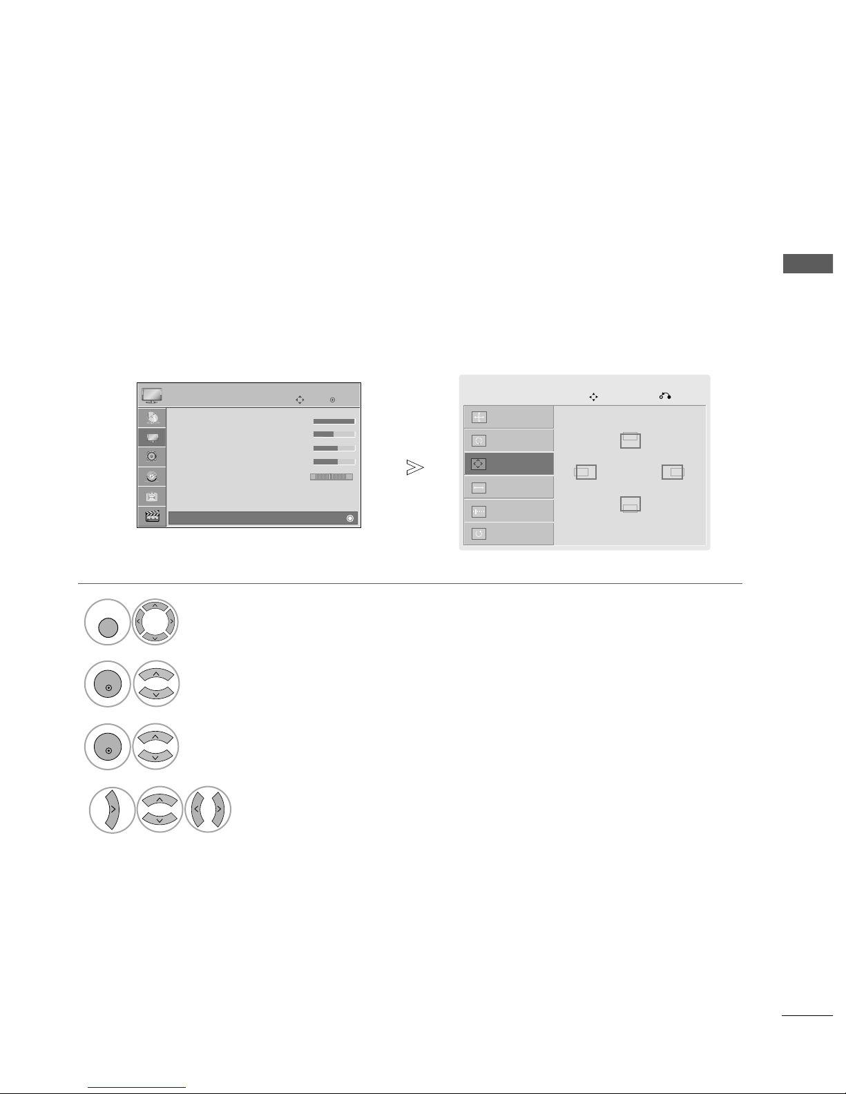
If the picture is not clear after auto adjustment and especially if characters are still trembling, adjust the picture
phase manually.
PPoo ss iittiioo nn
operates in Component(except 480i, 576i), RGB mode.
SS iizz ee,PPhhaa ss ee
operate only in RGB mode.
Adjustment for screen Position, Size, Phase
Select
PPIICC TTUURREE
.
Select
SScc rr ee ee nn
.
Select
PPoossiittii oo nn, SSiizz ee
or
PPhh aassee
.
Make appropriate adjustments.
1
MENU
3
4
2
OK
OK
• Press the
MMEENN UU
button to return to normal TV viewing.
•
Press the
RR EETTUURRNN
button to move to the previous menu screen.
OK
Move
• Contrast 100
• Brightness 50
• Sharpness 70
• Colour 70
• Tint 0
• Advanced Control
• Picture Reset
Screen
PICTURE
E
Screen
RG
GF
D
E
26
EXTERNAL EQIPMENT SETUP
EXTERNAL EQUIPMENT SETUP
Auto Config.
Screen
Move
Prev.
Resolution
G
Position
Size
Phase
Reset
To view a normal picture, match the resolution of RGB mode and selection of PC mode.
This function works in the following mode: RGB[PC]
Selecting Resolution (Except 42PQ2
***
, 42PQ3
***
, 42PQ6
***
)
Select
PPIICC TTUURREE
.
Select
SScc rr ee ee nn
.
Select
RReessoolluutt iioo nn
.
Select the desired resolution.
1024 x 768
1280 x 768
1360 x 768
1
MENU
3
4
2
OK
OK
• Press the
MMEENN UU
button to return to normal TV viewing.
• Press the
RR EETTUURRNN
button to move to the previous menu screen.
OK
Move
• Contrast 100
• Brightness 50
• Sharpness 70
• Colour 70
• Tint 0
• Advanced Control
• Picture Reset
Screen
PICTURE
E
Screen
RG
27
EXTERNAL EQUIPMENT SETUP
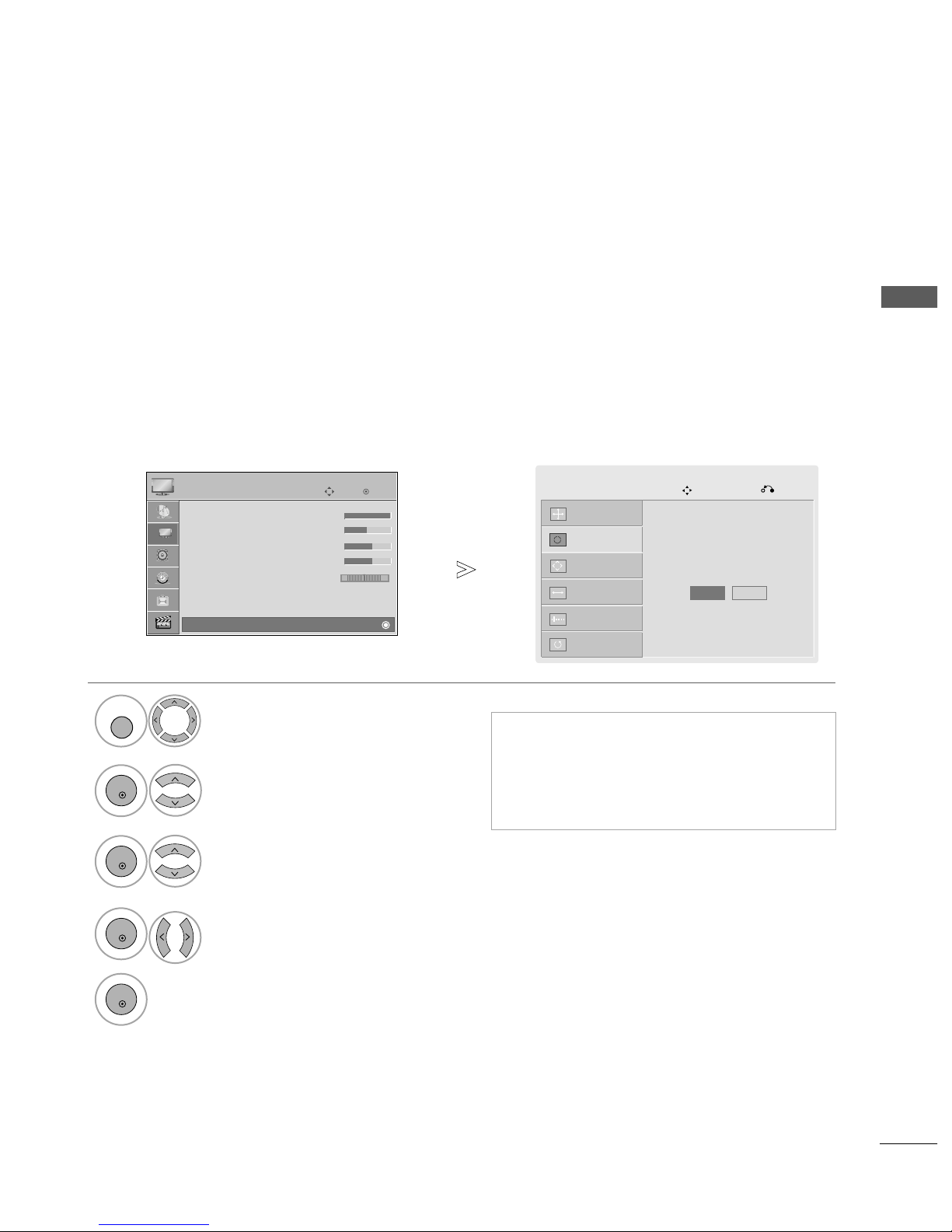
Automatically adjust the picture position and minimizes image instability. After adjustment, if the image is
still not correct, your TV is functioning properly but needs further adjustment.
AAuuttoo cc oonn ffii gguu rree
This function is for automatic adjustment of the screen position, size and phase The displayed image will be
unstable for a few seconds while the auto configuration is in progress.
Auto Configure (RGB [PC] mode only)
•
If the position of the image is still not correct,
try Auto adjustment again.
• If picture needs to be adjusted again after Auto
adjustment in RGB (PC), you can adjust the
PPoossiittii oo nn, SSiizz ee
or
PPhh aassee
.
Select
PPIICC TTUURREE
.
Select
SScc rr ee ee nn
.
Select
AAuu ttoo CCoo nnff iigg..
.
1
MENU
3
2
OK
OK
• Press the
MMEENN UU
button to return to normal TV viewing.
• Press the
RR EETTUURRNN
button to move to the previous menu screen.
Select
YYee ss
.
Run
AAuu ttoo CCoo nnff iigg..
.
4
OK
5
OK
OK
Move
• Contrast 100
• Brightness 50
• Sharpness 70
• Colour 70
• Tint 0
• Advanced Control
• Picture Reset
Screen
PICTURE
E
Screen
RG
Auto Config.
G
Screen
Move
Prev.
Resolution
Position
Size
Phase
Reset
To Set
Yes No

FAV
MARK
MENU
LIST
Q.VIEW
123
456
7809
MUTE
P
P
A
G
E
RETURN
INPUTRATIO
POWER
AV MODE
ENERGY SAVING
FREEZE
Q.MENU
OK
28
WATCHING TV / PROGRAMME CONTROL
WATCHING TV / PROGRAMME CONTROL
REMOTE CONTROL KEY FUNCTIONS
(EXCEPT 42/50PQ6
***
)
When using the remote control, aim it at the remote control sensor on the TV.
RATIO
AV MODE
POWER
INPUT
ENERGY
SAVING
Selects your desired picture format.
It helps you select and set images and sounds when
connecting AV devices.(
GG
pp.. 44 77
)
Switches the TV on from standby or off to standby.
External input mode rotate in regular sequence.
Switches the TV on from standby.
Adjust the power saving mode of the TV.
0~9 number
button
LIST
Q.VIEW
VOLUME UP
/DOWN
MUTE
Programme
UP/DOWN
PAG E
UP/DOWN
Selects a programme.
Selects numbered items in a menu.
Displays the programme table.
Returns to the previously viewed programme.
Adjusts the volume.
Switches the sound on or off.
Selects a programme.
Move from one full set of screen information to the next
one.
TELETEXT
BUTTONS
Coloured
buttons
These buttons are used for teletext.
For further details, see the ‘Teletext’ section.(
GG
pp.. 99 00
)
These buttons are used for teletext (on
TTEE LLEETTEEXXTT
models only) ,
PPrrooggrraa mm mm ee eeddiitt
.
1
1
 Loading...