

2 Plasma Monitor
Warning
WARNING:
TO REDUCE THE RISK OF ELECTRIC SHOCK DO NOT REMOVE COVER (OR BACK). NO USER
SERVICEABLE PARTS INSIDE. REFER TO QUALIFIED SERVICE PERSONNEL.
The lightning flash with arrowhead symbol, within an equilateral triangle, is intended to alert the user to
the presence of uninsulated “dangerous voltage” within the product’s enclosure that may be of sufficient magnitude to constitute a risk of electric shock to persons.
The exclamation point within an equilateral triangle is intended to alert the user to the presence of
important operating and maintenance (servicing) instructions in the literature accompanying the appliance.
WARNING:
TO PREVENT FIRE OR SHOCK HAZARDS, DO NOT EXPOSE THIS PRODUCT TO RAIN OR MOISTURE.
FCC NOTICE
• A Class B digital device
This equipment has been tested and found to comply with the limits for a Class B digital device, pursuant to Part
15 of the FCC Rules. These limits are designed to provide reasonable protection against harmful interference in
a residential installation. This equipment generates, uses and can radiate radio frequency energy and, if not
installed and used in accordance with the instructions, may cause harmful interference to radio communications.
However, there is no guarantee that interference will not occur in a particular installation. If this equipment does
cause harmful interference to radio or television reception, which can be determined by turning the equipment off
and on, the user is encouraged to try to correct the interference by one or more of the following measures:
- Reorient or relocate the receiving antenna.
- Increase the separation between the equipment and receiver.
- Connect the equipment into an outlet on a circuit different from that to which the receiver is connected.
- Consult the dealer or an experienced radio/TV technician for help.
• Any changes or modifications not expressly approved by the party responsible for compliance could void the user’s warranty.
CAUTION:
Do not attempt to modify this product in any way without written authorization from LG Electronics. Unauthorized modification could void the user’s warranty.
COMPLIANCE:
The responsible party for this product’s compliance is:
LG Electronics U.S.A., Inc
1000 Sylvan Avenue, Englewood Cliffs, NJ 07632
1-800-243-0000
http://www.lgusa.com
WARNING
RISK OF ELECTRIC SHOCK
DO NOT OPEN
/CAUTION
W
W
arning
arning
Owner’s Manual 3
Safety Instructions
Safety Instructions
Safety Instructions
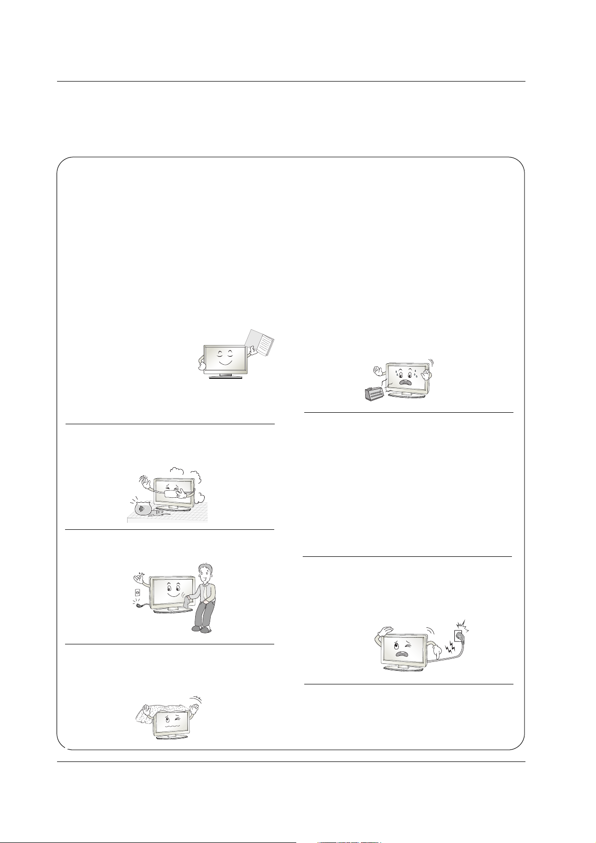
IMPORTANT SAFETY INSTRUCTIONS
Important safety instructions shall be provided with each apparatus. This information shall be given in a separate booklet
or sheet, or be located before any operating instructions in an instruction for installation for use and supplied with the apparatus.
This information shall be given in a language acceptable to the country where the apparatus is intended to be used.
The important safety instructions shall be entitled “Important Safety Instructions”. The following safety instructions shall be
included where applicable, and, when used, shall be verbatim as follows. Additional safety information may be included by
adding statements after the end of the following safety instruction list. At the manufacturer’s option, a picture or drawing that
illustrates the intent of a specific safety instruction may be placed immediately adjacent to that safety instruction :
1. Read these instructions.
2. Keep these instructions.
3. Heed all warnings.
4. Follow all instructions.
5. Do not use this apparatus near water.
6. Clean only with dry cloth.
7. Do not block any ventilation openings. Install in accor-
dance with the manufacturer’s instructions.
8. Do not install near any heat sources such as radiators,
heat registers, stoves, or other apparatus (including ampli-
fiers)that produce heat.
9. Do not defeat the safety purpose of the polarized or
grounding-type plug. A polarized plug has two blades with
one wider than the other. A grounding type plug has two
blades and a third grounding prong, The wide blade or the
third prong are provided for your safety. If the provided plug
does not fit into your outlet, consult an electrician for replace-
ment of the obsolete outlet.
10. Protect the power cord from being walked on or pinched
particularly at plugs, convenience receptacles, and the point
where they exit from the apparatus.
11. Only use attachments/accessories specified by the man-
ufacturer.
O
w
n
e
r
's
M
a
n
u
a
l
4 Plasma Monitor
Safety Instructions
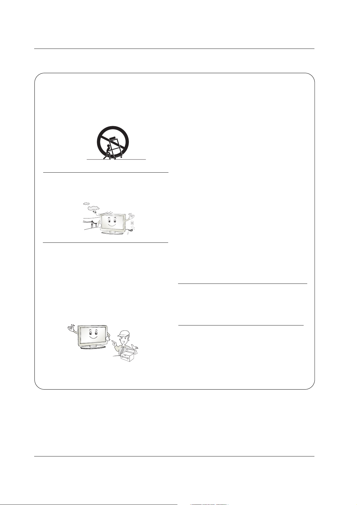
12. Use only with the cart, stand, tripod, bracket, or table
specified by the manufacturer, or sold with the apparatus.
When a cart is used, use caution when moving the
cart/apparatus combination to avoid injury from tip-over.
13. Unplug this apparatus during lightning storms or when
unused for long periods of time.
14. Refer all servicing to qualified service personnel.
Servicing is required when the apparatus has been dam-
aged in any way, such as power-supply cord or plug is dam-
aged, liquid has been spilled or objects have fallen into the
apparatus, the apparatus has exposed to rain or moisture,
does not operate normally, or has been dropped.
15. CAUTION concerning the Power Cord :
Most appliances recommend they be placed upon a dedi-
cated circuit; that is, a single outlet circuit which powers only
that appliance and has no additional outlets or branch cir-
cuits. Check the specification page of this owner's manual to
be certain.
Do not overload wall outlets. Overloaded wall outlets, loose
or damaged wall outlets, extension cords, frayed power
cords, or damaged or cracked wire insulation are dangerous.
Any of these conditions could result in electric shock or fire.
Periodically examine the cord of your
appliance, and if its appearance indicates damage or deteri-
oration, unplug it, discontinue use of the appliance, and have
the cord replaced with an exact replacement part by an
authorized servicer.
Protect the power cord from physical or mechanical abuse,
such as being twisted, kinked, pinched, closed in a door, or
walked upon. Pay particular attention to plugs, wall outlets,
and the point where the cord exits the appliance.
16. Outdoor Use Marking :
WARNING - To Reduce The Risk Of Fire Or Electric Shock,
Do Not Expose This Appliance To Rain Or Moisture.
17. Wet Location Marking :
Apparatus shall not be exposed to dripping or splashing and
no objects filled with liquids, such as vases, shall be placed
on the apparatus.
PORTABLE CART WARNING

Owner’s Manual 5
Contents
Safety Instructions . . . . . . . . . . . . . . . . . . . . . . . . . . . . .2~4
Introduction
Features Of This monitor . . . . . . . . . . . . . . . . . .6
Accessories . . . . . . . . . . . . . . . . . . . . . . . . . . . .7
Controls and Connection Options . . . . . . . . . .8~9
Remote Control Key Functions . . . . . . . . . . . . .10
Installation
Desktop Pedestal Installation . . . . . . . . . . . . . . . .11
External Equipment Connections
VCR Setup . . . . . . . . . . . . . . . . . . . . . . . . . . . .12
Cable TV Setup . . . . . . . . . . . . . . . . . . . . . . . .13
External A/V Source Setup . . . . . . . . . . . . . . . .13
DVD Setup . . . . . . . . . . . . . . . . . . . . . . . . . . . .14
DTV Setup . . . . . . . . . . . . . . . . . . . . . . . . . . . .15
PC Setup . . . . . . . . . . . . . . . . . . . . . . . . . .16~17
Operation
Turning on the Monitor . . . . . . . . . . . . . . . . . . . . .18
Menu Language Selection . . . . . . . . . . . . . . . . . .18
On Screen Menus Selection . . . . . . . . . . . . . . . . .19
Picture Menu Options
Picture Status Memory (PSM) . . . . . . . . . . . . . .20
Manual Picture Control . . . . . . . . . . . . . . . . . .20
Color Status Memory (PSM) . . . . . . . . . . . . . . .21
Manual Color Temperature Control . . . . . . . . . .21
XD . . . . . . . . . . . . . . . . . . . . . . . . . . . . . . . . . .22
Picture Reset . . . . . . . . . . . . . . . . . . . . . . . . . .22
Advanced - Cinema 3:2 Pull down mode . . . . . .23
Advanced - Black level . . . . . . . . . . . . . . . . . . .23
Sound Menu Options
Sound Status Memory (SSM) . . . . . . . . . . . . . .24
Manual Sound Control . . . . . . . . . . . . . . . . . . .24
AVL (Auto Volume Leveler) . . . . . . . . . . . . . . . .25
Balance . . . . . . . . . . . . . . . . . . . . . . . . . . . . . .25
TV Speaker on/off setup . . . . . . . . . . . . . . . . . .25
Timer Menu Options
Clock Setup . . . . . . . . . . . . . . . . . . . . . . . . . . .26
On/Off Timer Setup . . . . . . . . . . . . . . . . . . . . .26
Auto Sleep . . . . . . . . . . . . . . . . . . . . . . . . . . . .27
Sleep Timer . . . . . . . . . . . . . . . . . . . . . . . . . . .27
Special Menu Options
Child Lock . . . . . . . . . . . . . . . . . . . . . . . . . . . .28
ISM Method . . . . . . . . . . . . . . . . . . . . . . . . . . .28
Tile mode . . . . . . . . . . . . . . . . . . . . . . . . . . . . .29
Low power . . . . . . . . . . . . . . . . . . . . . . . . . . . .30
XD demo . . . . . . . . . . . . . . . . . . . . . . . . . . . . .30
Screen Menu Options
Auto Adjustment . . . . . . . . . . . . . . . . . . . . . . . .31
Manual Configure . . . . . . . . . . . . . . . . . . . . . . .31
Selecting XGA mode . . . . . . . . . . . . . . . . . . . . .32
Picture Size Control . . . . . . . . . . . . . . . . . . . . .32
Screen Position . . . . . . . . . . . . . . . . . . . . . . . .29
Initializing . . . . . . . . . . . . . . . . . . . . . . . . . . . . .33
External Control Device Setup . . . . . . . . . . . . . . . .34~39
IR Code . . . . . . . . . . . . . . . . . . . . . . . . . . . . . . . . .40~41
Troubleshooting Checklist . . . . . . . . . . . . . . . . . . .42~43
Troubleshooting Checklist . . . . . . . . . . . . . . . . . . . . . .44
Specifications . . . . . . . . . . . . . . . . . . . . . . . . . . . . . . . .45
Contents
Contents
After reading this manual, keep it handy for future reference.

6 Plasma Monitor
Introduction
Introduction
Introduction
Features Of This Monitor
Features Of This Monitor
What is a Plasma Monitor ?
If voltage is applied to gas within glass panels, ultraviolet rays are produced and fused with a fluorescent substance. At that
instant, light is emitted. A Plasma Display is a next generation flat Display using this phenomenon.
160° - Wide angle range of vision
Your flat panel plasma screen offers an exceptionally broad viewing angle -- over 160 degrees. This means that the display is
clear and visible to viewers anywhere in the room.
Wide Screen
The screen of the Plasma Display is 71" so wide that your viewing experience is as if you are in a theater.
Multimedia
Connect your plasma display to a PC and you can use it for conferencing, games, and internet browsing. The Picture-in-Picture
feature allows you to view your PC and video images simultaneously.
Versatile
The light weight and thin size makes it easy to install your plasma display in a variety of locations where conventional TVs would
not fit.
The Plasma Monitor Manufacturing Process: Why minute colored dots may be present on the Plasma
Monitor screen
The Plasma Display Panel which is the display device of this product is composed of 0.9 to 2.2 million cells. A few cell defects will
normally occur in the Plasma Monitor manufacturing process. Several minute colored dots visible on the screen should be acceptable. This also occurs in other Plasma Monitor manufacturers' products and the tiny dots appearing does not mean that this
Plasma Monitor is defective. Thus a few cell defects are not sufficient cause for the Plasma Monitor to be exchanged or returned.
Our production technology is designed to minimize cell defects during the manufacture and operation of this product.
Cooling Fan Noise
In the same way that a fan is used in a PC computer to keep the CPU (Central Processing Unit) cool, the Plasma Monitor is
equipped with cooling fans to cool the Monitor and improve its reliability. Therefore, a certain level of noise could occur while the
fans are operating and cooling the Plasma Monitor.
The fan noise doesn't have any negative effect on the Plasma Monitor's efficiency or reliability. The noise from these fans is normal during the operation of this product. We hope you understand that a certain level of noise from the cooling fans is acceptable
and is not sufficient cause for the Plasma Monitor to be exchanged or returned.
Owner’s Manual 7
Introduction
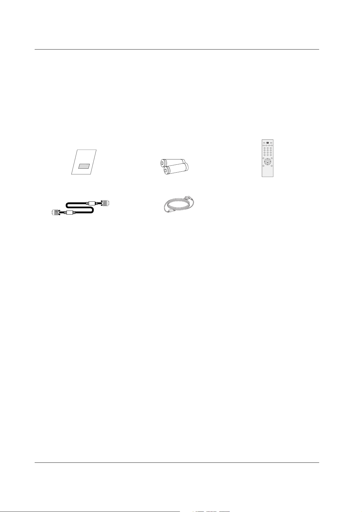
Ensure that the following accessories are included with your plasma display. If an accessory is missing, please contact the dealer
where you purchased the product.
Owner’s Manual
1.5V
1.5V
Batteries
Power Cord
123
456
78
0
**
*
9
SET
POWER
SLEEPAVPSM ARC AUTO
INPUT
VOL VOL
MENU
MUTE
EXIT
Remote Control
D-sub 15 pin cable
Accessories
Accessories
8 Plasma Monitor
Introduction
Controls
Controls
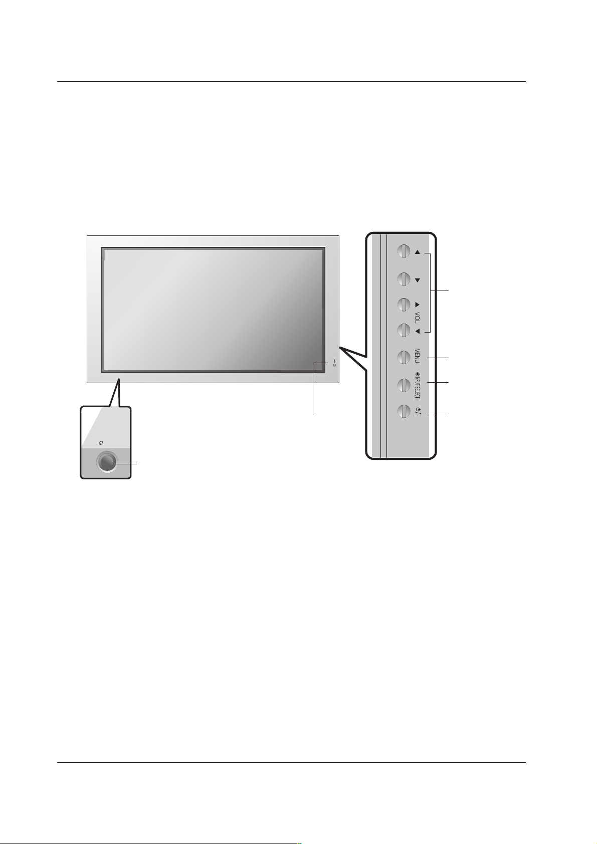
- This is a simplified representation of front panel.
- This picture shown below may be somewhat different from your monitor.
1.Power Standby Indicator
Illuminates red in standby mode, Illuminates green when the
Set is turned on.
2. Remote Control Sensor
3. VOLUME (FF,GG) Buttons
EE, DD
Buttons
4. MENU Button
5. INPUT SELECT Button
6. Main Power Button
Switches the set on from standby or off to standby.
5
6
4
3
2
1
7
ON/OFF
Owner’s Manual 9
Introduction
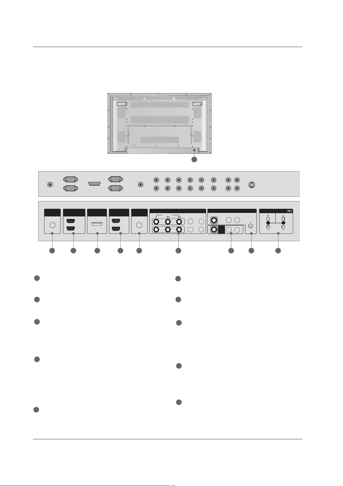
Connection Options
Connection Options
REMOTE CONTROL IN
Connect your wired remote control.
RS-232C IN (CONTROL & SERVICE) PORT
Connect to the RS-232C port on a PC.
HDMI/DVI IN
Connect a HDMI signal to 1(DVI) or 2.
Or DVI(VIDEO) signal to the 1(DVI) port with a DVI to
HDMI cable.
RGB INPUT
Connect the set output connector from a PC to the
appropriate input port.
RGB OUTPUT
You can watch the RGB signal on another set, connect
RGB OUTPUT to another set’s PC input port.
AUDIO (RGB/DVI)
Connect the monitor output from a PC to the appropriate
input port.
COMPONENT IN
Connect a component video/audio device to these jacks.
AV OUTPUT
Connect a second Set or monitor.
VIDEO IN
Connect audio/video output from an external device to
these jacks.
S-VIDEO
Connect S-Video out from an S-VIDEO device.
EXTERNAL SPEAKER (8 ohm output)
Connect to optional external speaker(s).
* For further information, refer to ‘Speaker & Speaker
Stand’ manual.
POWER CORD SOCKET
This Monitor operates on an AC power. The voltage is
indicated on the Specifications page. Never attempt to
operate the Monitor on DC power.
1
7
2
3
4
5
6
8
9
10
- Connection panels shown may be somewhat different from your Monitor.
1 2 3 4 6 7 8 95
10
REMOTE
CONTROL IN
RS-232C
(CONTROL&SERVICE)
HDMI/DVI IN
OUT
IN
RGB
(RGB/DVI)
IN
OUT
AUDIO
COMPONENT IN
VIDEO
1
2
L-AUDIO-R
VIDEO
AV
OUT
AV IN
L-AUDIO-R
S-VIDEO
EXTERNAL SPEAKER
R
L
10 Plasma Monitor
Introduction
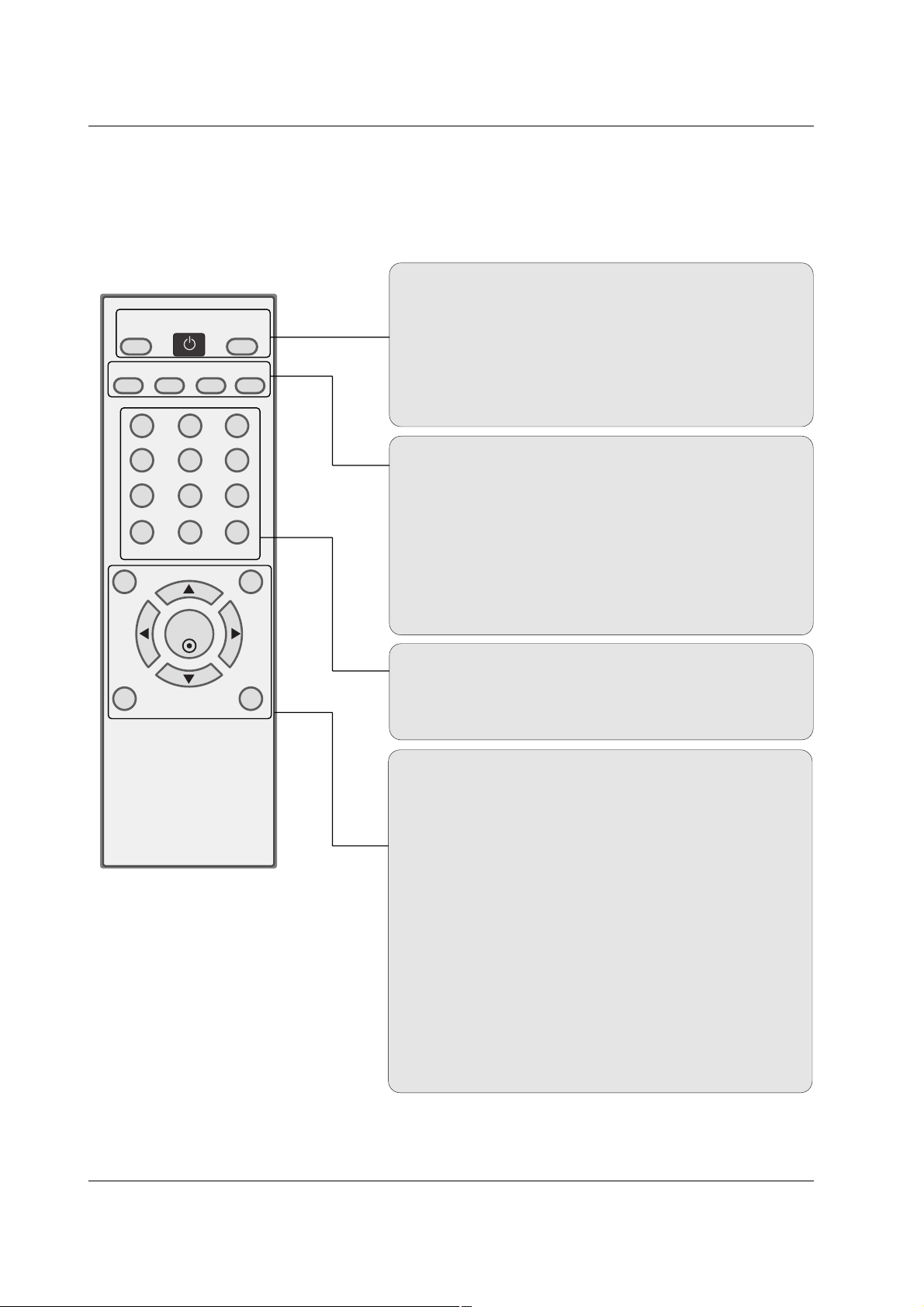
- When using the remote control, aim it at the remote control sensor on the monitor.
- Under certain conditions such as if the remote IR signal is interrupted, the remote control may not function. Press
the key again as necessary.
Remote Control Key Functions
Remote Control Key Functions
123
456
78
0
**
*
9
SET
POWER
SLEEPAVPSM ARC AUTO
INPUT
VOL VOL
MENU
MUTE
EXIT
AV
Selects: AV, Component 1-2, RGB, HDMI/DVI input sources.
POWER
Turns your monitor or any other programmed equipment on or
off, depending on mode.
INPUT
Selects: AV, Component 1-2, RGB, HDMI/DVI input sources.
AUTO
Automatic adjustment function
SLEEP
Sets the Sleep Timer.
PSM
Adjusts the factory preset picture according to the room.
ARC
Changes the picture format.
NUMBER buttons
Dosen’t work for monitor mode.
*
Not functional
MENU
Brings up the main menu to the screen.
EXIT
Clears all on-screen displays and returns to monitor viewing
from any menu.
VOLUME UP/DOWN
Increases/decreases the sound level.
THUMBSTICK (Up/Down/Left/Right/SET)
Navigate the on-screen menus and adjust the system settings to your preference.
MUTE
Switches the sound on or off.
*
Not functional
Installing Batteries
• Open the battery compartment cover on the
back side and install the batteries matching
correct polarity (+ with +, - with -).
• Install two 1.5V AA batteries. Don’t mix old
or used batteries with new ones.
Replace cover.
Owner’s Manual 11
Introduction
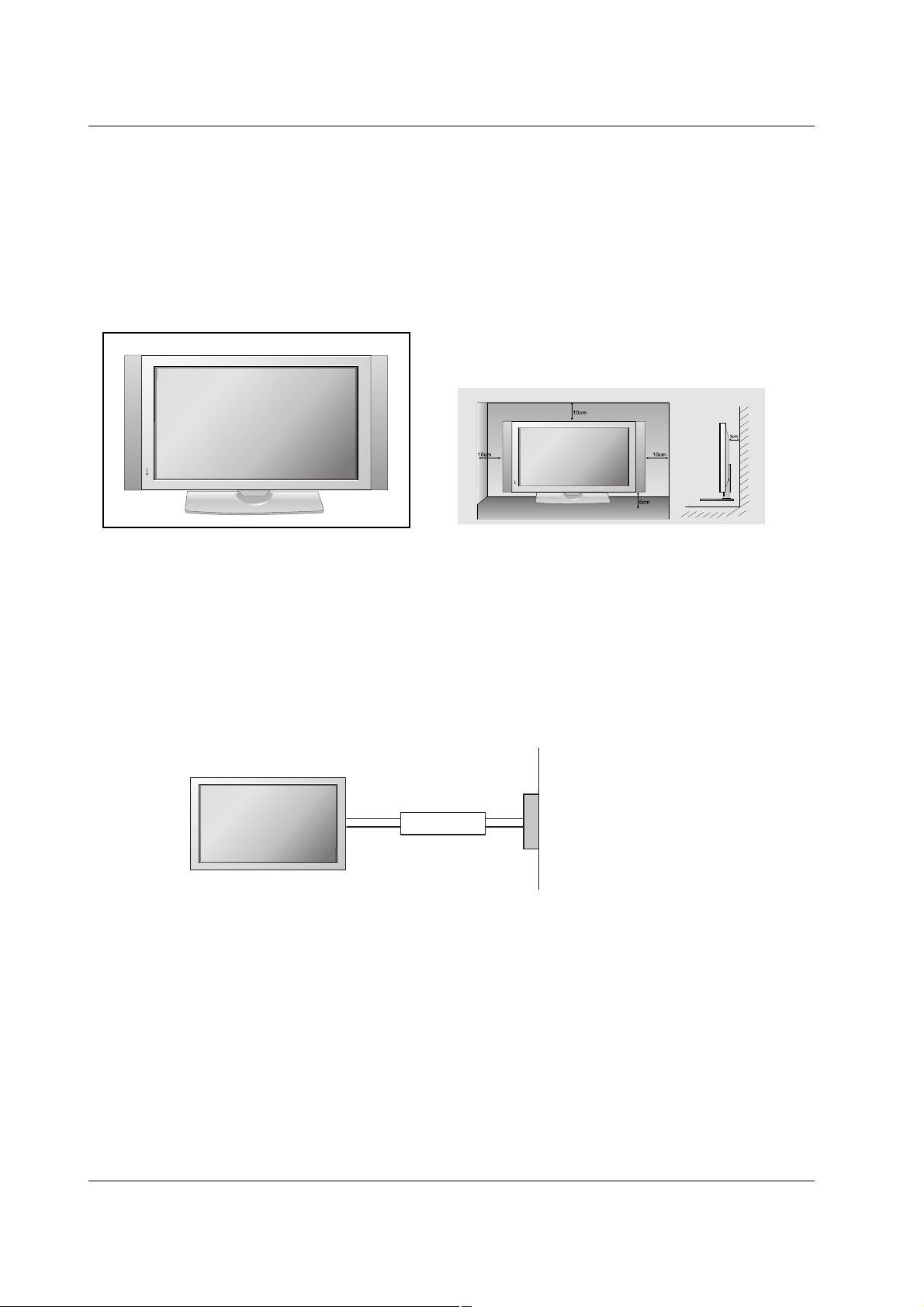
Desktop Pedestal Installation
Desktop Pedestal Installation
GROUNDING
Ensure that you connect the grounding / earth wire to prevent possible electric shock. If grounding
methods are not possible, have a qualified electrician install a separate circuit breaker. Do not try
to ground the unit by connecting it to telephone wires, lightening rods, or gas pipes.
Power Supply
Short-circuit Breaker
For proper ventilation, allow a clearance of 4inches on each side from the wall.
Installation
Installation
• This picture shown below may be somewhat different from your monitor.
12 Plasma Monitor
Installation
External Equipment Connections
External Equipment Connections
NOTE: Not all cables shown are included with the plasma display.
VCR Setup
VCR Setup
L R
S-VIDEO VIDEO
OUTPUT
SWITCH
ANT IN
ANT OUT
NENT IN
1
2
L-AUDIO-R
VIDEO
AV
OUT
AV I N
L-AUDIO-R
S-VIDEO
EXTERNAL SPEAK
R
1
2
L-AUDIO-R
VIDEO
AV
OUT
AV I N
L-AUDIO-R
S-VIDEO
EXTERNAL SPEAKER
R
L
L R
S-VIDEOVIDEO
OUTPUT
SWITCH
ANT IN
ANT OUT
VCR
VCR
- To avoid picture noise (interference), leave an adequate distance between the VCR and monitor.
- Use the ISM Method (on the Special menu) feature to avoid having a fixed image remain on the screen for a long period of
time. Typically a frozen still picture from a VCR. If the 4:3 picture format is used; the fixed images on the sides of the screen
may remain visible on the screen.
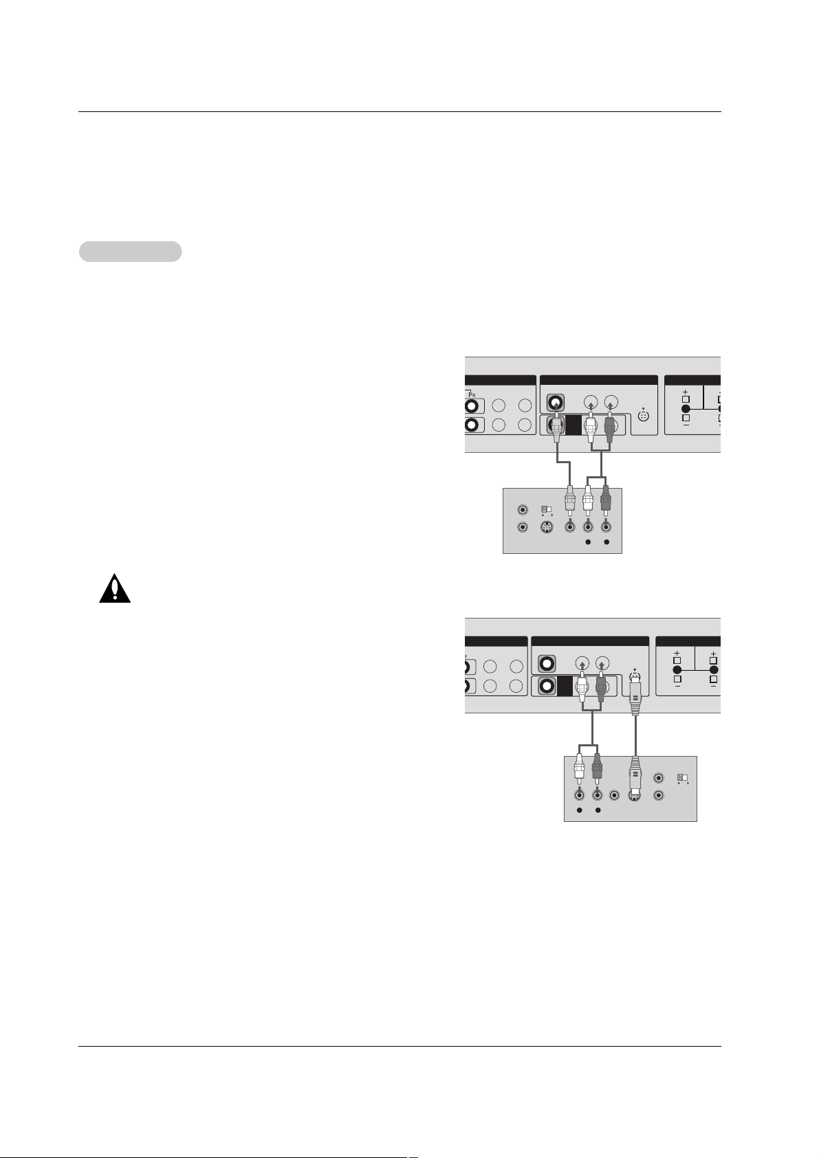
Connection Option
1. Connect the audio and video cables from the VCR's output
jacks to the set input jacks, as shown in the figure.
When connecting the set to VCR, match the jack colors
(Video = yellow, Audio Left = white, and Audio Right = red).
If you connect an S-VIDEO output from VCR to the S-VIDEO
input, the picture quality is improved; compared to connecting a regular VCR to the Video input.
2. Insert a video tape into the VCR and press PLAY on the
VCR. (Refer to the VCR owner’s manual.)
3. Select the input source with using the INPUT button on the
remote control.
Do not connect to both Video and SVideo at the same time. In the event
that you connect both Video and the
S-Video cables, only the S-Video will
work.
Owner’s Manual 13
Installation
- After subscribing to a cable monitor service from a local provider and installing a converter, you can watch cable TV program-
ming. The monitor cannot display monitor programming unless a TV tuner device or cable TV converter box is connected to the
Monitor.
- For further information regarding cable monitor service, contact your local cable TV service provider(s).
How to connect
1. Connect the audio and video cables from the Cable Box's output
jacks to the monitor input jacks, as shown in the figure.
When connecting the monitor to a Cable Box, match the jack colors
(Video = yellow, Audio Left = white, and Audio Right = red).
Or, connect the Euro scart socket of the Cable box to the Euro scart
socket of the set.
How to use
1. Use the INPUT button on the remote control to select AV .
2. Select your desired channel with the remote control for cable box.
Cable
Cable
TV Setup
TV Setup
1
2
L-AUDIO-R
VIDEO
AV
OUT
AV IN
L-AUDIO-R
S-VIDEO
EXTERNAL SPEAKER
R
L
TV
VCR
RF Cable
(R) AUDIO (L) VIDEO
34
OUTPUT
SWITCH
Cable Box
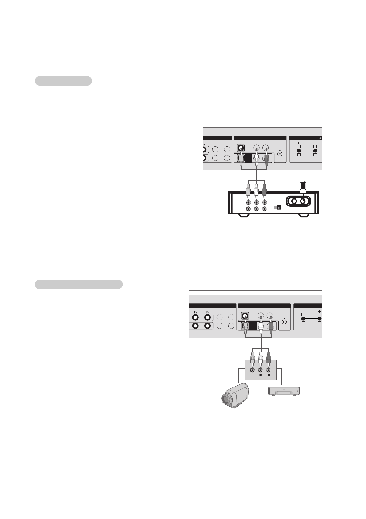
How to connect
1. Connect the audio and video cables from the external
equipment's output jacks to the monitor input jacks, as
shown in the figure.
When connecting the monitor to external equipment, match
the jack colors (Video = yellow, Audio Left = white, and
Audio Right = red).
Or, connect the Euro scart socket of the External A/V to the
Euro scart socket of the set.
How to use
1. Use the INPUT button on the remote control to select AV .
2. Operate the corresponding external equipment. Refer to
external equipment operating guide.
External
External
A/V Source Setup
A/V Source Setup
COMPONENT IN
1
2
VIDEO
L-AUDIO-R
VIDEO
AV
OUT
AV IN
L-AUDIO-R
S-VIDEO
EXTERNAL SPEAKER
R
L
L R
VIDEO
14 Plasma Monitor
Installation
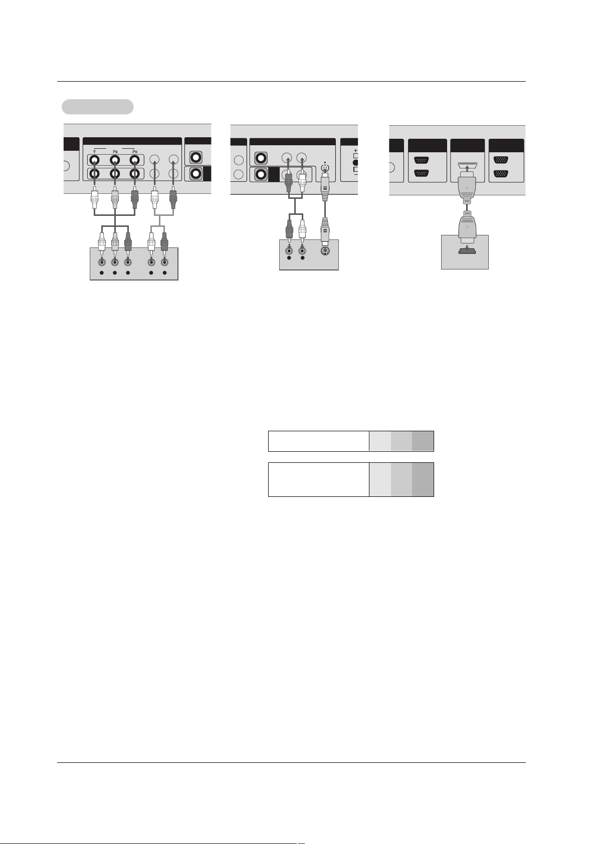
• Component Input ports
To get better picture quality, connect a DVD
player to the component input ports as shown.
Component ports of the
Monitor
Y
PB
PR
Video output ports
of DVD player
Y
Y
Y
Y
Pb
B-Y
Cb
P
B
Pr
R-Y
Cr
PR
How to connect
1. Connect the DVD video outputs to the COMPONENT (Y, P
B, PR) or HDMI IN 1(DVI) jacks and connect the DVD audio outputs
to the AUDIO INPUT jacks on the monitor, as shown in the figure.
2. If your DVD only has an S-Video output jack, connect this to the S-VIDEO input on the monitor and connect the DVD audio out-
puts to the AUDIO INPUT jacks on the monitor, as shown in the figure.
How to use
1. Turn on the DVD player, insert a DVD.
2. Use the INPUT button on the remote control to select Component 1, Component 2, or HDMI/DVI. (If connected to S-VIDEO,
select the AV external input source.)
3. Refer to the DVD player's manual for operating instructions.
DVD Setup
DVD Setup
DVD
COMPONENT IN
1
2
VIDEO
VIDEO
AV
OU
L-AUDIO-R
Y L RPB PR
L-AUDIO-R
VIDEO
AV
OUT
AV IN
S-VIDEO
EXTER
R
L R
S-VIDEO
AUDIO
OUT
IN
HDMI/DVI IN
RS-232C
(CONTROL&SERVICE)
IN
OUT
RGB
HDMI-DVD OUTPUT
Owner’s Manual 15
Installation
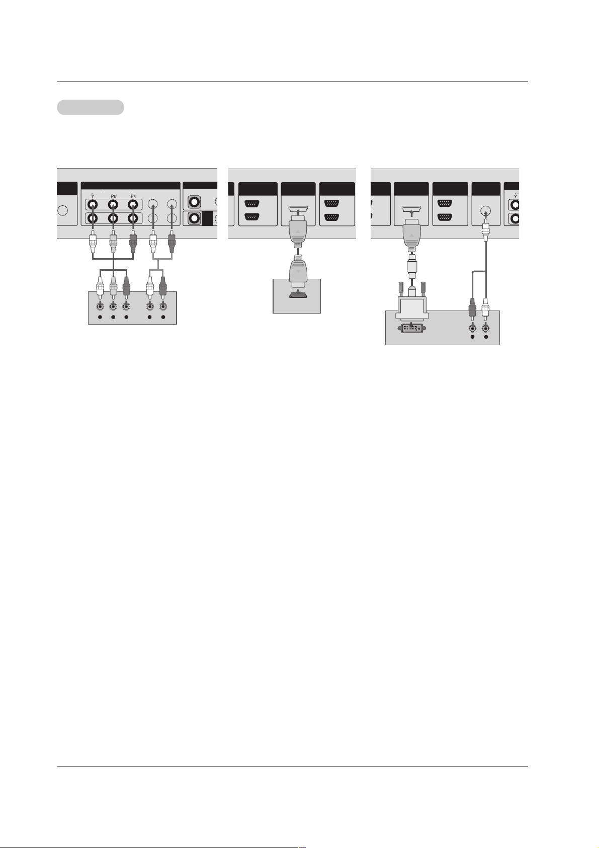
How to connect
1. Use the monitor’s COMPONENT (Y, P
B, PR) INPUT, RGB or HDMI IN 1(DVI) to HDMI jack for video connec-
tions, depending on your set-top box connector. Then, make the corresponding audio connections.
How to use
1. Turn on the digital set-top box. (Refer to the owner’s manual for the digital set-top box.)
2. Use INPUT on the remote control to select Component 1, Component 2, RGB, or HDMI/DVI.
DTV Setup
DTV Setup
COMPONENT IN
1
2
VIDEO
VIDEO
AV
OUT
L-AUDIO-R
Y L RPB PR
OUT
IN
IN
HDMI/DVI IN
RS-232C
(CONTROL&SERVICE)
IN
OUT
RGB
HDMI-DTV OUTPUT
OUT
IN
HDMI/DVI IN
IN
OUT
RGB
AUDIO
(RGB/DVI)
L R
DVI-DTV OUTPUT
Digital Set-top Box
- To watch digitally broadcast programs, purchase and connect a digital set-top box.
- This monitor supports HDCP (High-bandwidth Digital Contents Protection) protocol for
HDMI/DVI-DTV (480p,720p,1080i, 1080p) mode.
 Loading...