

LG 50PM1MH, 42PM1MH-TA, 50PM1M, 50PM1M-TA, 42PM1M-ZA Owner's Manual
...
User’s Guide Specification
User’s Guide Specification
담 당 관리자
Model Description
1.
MODEL
SUFFIX
2.
RF052A
WITH AV
Printing Specification
1. Trim Size (Format) : 185 mm x 260 mm
2. Printing Colors : 1 Color (BLACK)
3. Stock (Paper) : Uncoated paper, WHITE PAPER 80 g/㎡
4. Printing Method :
5. Bindery : Saddle stitch
6. Language : EN
7. Number of pages : 40 pages
•This part contain Eco-hazardous substances (Pb, Cd, Hg, Cr6+, PBB, PBDE, etc.) within LG
standard level, Details should be followed Eco-SCM management standard[LG(56)-A-2524].
Especially, Part should be followed and controlled the following specification.
(1)Eco-hazardous substances test report should be submitted when Part certification test
and First Mass Production.
(2) Especially, Don’t us e or contain lead(Pb) and cadmium(Cd) in ink.
BRAND
Product Name
LG
OWNER’S MANUAL
CHOI MJ
06.08.17
Part No.
KANG KS
06.08.17
38289U0515A
Special Instructions3.
(1) Origin Notification
* LGEDI : Printed in Indonesia * LGEWA : Printed in U.K. * LGEMA : Printed in Poland
* LGESP : Printed in Brazil * LGEMX : Printed in Mexico
* LGENT : Printed in China * LGEIL : Printed in India
* Other Oversea Factories : NON
4.
Changes
10
9
8
7
6
5
4
3
2
08/17/06 CHOI MJ S6-53145
1
REV.
NO.
MM/DD/YY
SIGNATURE
CHANGE NO.
Amend Printing Specification
CHANGE CONTENTS
Pagination sheet
Pagination sheet
P/NO. 38289U0515A
Total pages : 40 pages
Front
Cover
(EN)
P/NO.
23…
Back
Cover
(EN)
11 39…21…

Please read this manual carefully before operating your set.
Retain it for future reference.
Record model number and serial number of the set.
See the label attached on the back cover and quote this information to your dealer when you require service.
Model number :
Serial number :
PLASMA MONITOR
OWNER’S MANUAL
P/NO : 38289U0515A (RF052A, 017M/N TX) a

2 PLASMA MONITOR
Safety Warnings
Safety Instructions
Safety Instructions
Do not place the set in direct sunlight or near heat
sources such as heat registers, stove and so on.
- This may cause a fire.
Do not use the set in damp place such as a bathroom
or any place where it is likely to get wet.
- This may cause a fire or could give an electric shock.
Bend antenna cable between inside and outside
building to prevent rain from flowing in.
- This may cause water damaged inside the set and could give an
electric shock.
Earth wire should be connected.
- If the earth wire is not connected, there is possible a danger of
electric shock caused by the current leakage.
- If grounding methods are not possible, a separate circuit breaker should be employed and installed by a qualified electrician.
- Do not connect ground to telephone wires, lightning rods or gas
pipe.
Apparatus shall not be exposed to dripping or splashing and no objects filled with liquids, such as vases,
shall be placed on the apparatus.
Do not insert any object into the exhaust vent.
- This may cause a fire or could give an electric shock.
Do not place heavy objects on the set.
- This may cause serious injury to a child or adult.
Do not use water while cleaning the set.
- This may cause damaged the set or could give an electric
shock.
In case of smoke or strange smell from the set, switch
it off ,unplug it from the wall outlet and contact your
dealer or service center.
- This may cause a fire or could give an electric shock.
Do not attempt to service the set yourself. Contact
your dealer or service center.
- This may cause damaged the set or could give an electric
shock.
During a lightning thunder, unplug the set from the
wall outlet and don’t touch an antenna cable.
- This may cause damaged the set or could give an electric
shock.
DISCONNECTING DEVICE FROM MAINS
- Mains plug is the disconnecting device. The plug must remain
readily operable.
Use a dedicated power cord. Do not modify or extend
the power cord.
Do not install, remove, or reinstall the unit by yourself
(customer).
For electrical work, contact the dealer, seller, a
qualified electrician, or an Authorized Service
Center. For installation, always contact the dealer or
an Authorized Service Center.
Do not use if the power cord or plug is damaged, or
socket is loose. Use a dedicated outlet for this
appliance.
Do not over bend the power cord and do not place
anything on the power cord. Do not install the
monitor near any sharp edge to avoid wire damage.
W
WARNING
Short-circuit
breaker
Power
supplier
• It is recommended that 42/50PM1MH / 60PZ9MH / 42PM3MVH model only be used at an altitude of less than
6561 feet (2000m) to get the best quality picture and sound.
WARNING
in U.K. only
*
This set is supplied with a BS 1363 approved 13 amp mains plug, fused at 13 amp. When replacing the fuse
always use a 13 amp BS 1362, BSI or ASTA approved type. Never use this plug with the fuse cover omitted. To
obtain a replacement fuse cover contact your dealer or “LG Electronics U.K. Ltd.” If the type of plug supplied is not
suitable for the mains sockets in your home, then the plug should be removed and a suitable type fitted.
A mains plug removed from the mains lead of this set must be destroyed. A mains plug with bared wires is
hazardous if inserted in a mains socket. Do not connect either wire to the earth pin, marked with the letter E or
with the earth symbol or coloured green or green and yellow. If any other plug is fitted, use a 13 amp fuse,
either in the plug, or at the distribution board.
The wires in this mains lead are coloured in accordance with the following codes:
As the colours of the wires in the mains lead of this set may not correspond with the coloured marking identifying the terminals in your plug, proceed as follows: The wire which is coloured blue must be connected to the terminal which is marked with the letter N or coloured black. The wire which is coloured brown must be connected
to the terminal which is marked with the letter L or coloured red.
BLUE: NEUTRAL, BROWN: LIVE
Owner’s Manual 3
Safety Warnings
Never touch the power plug with a wet hand.
- This may cause an electric shock.
Disconnect from the mains and remove all connections before moving.
Do not place the set in a built-in installation such as a
bookcase or rack.
- Ventilation required.
When installing the set on a table, be careful not to
place the edge of its stand.
- This may cause the set to fall, causing serious injury to a child or
adult, and serious damage to the set.
Do not place an outside antenna in the vicinity of overhead power lines or other electric light or power circuits.
- This may cause an electric shock.
There should be enough distance between an outside
antenna and power lines to keep the former from
touching the latter even when the antenna falls.
- This may cause an electric shock.
Do not pull the cord but the plug when unplugging.
- This may cause a fire.
Ensure the power cord doesn’t trail across any hot
objects like a heater.
- This may cause a fire or an electric shock.
Do not plug when the power cord or the plug is damaged or the connecting part of the power outlet is
loose.
- This may cause a fire or an electric shock.
Dispose of used batteries carefully to protect a child
from eating them.
- In case that it eats them, take it to see a doctor immediately.
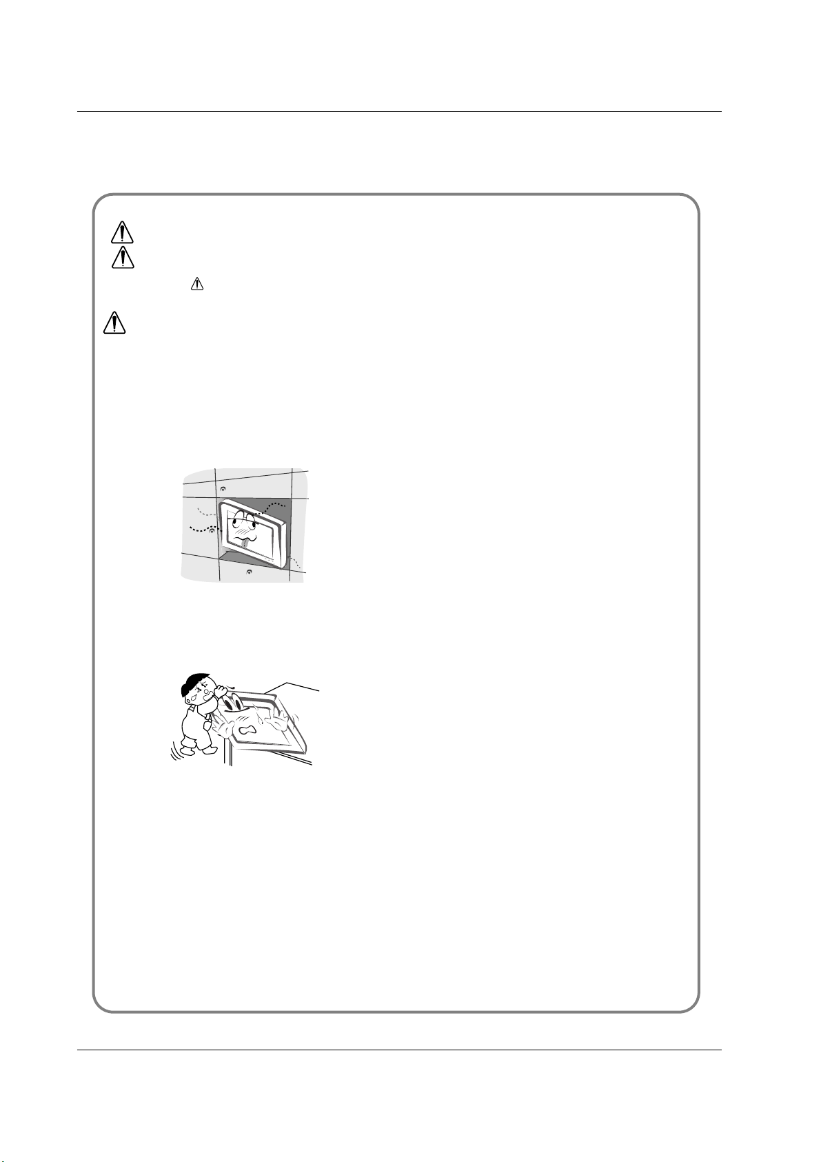
When moving the set assembled with speakers do not
carry holding the speakers.
- This may cause the set to fall, causing serious injury to a child or
adult, and serious damage to the set.
Unplug this product from the wall outlet before cleaning. Do not use liquid cleaners or aerosol cleaners.
- This may cause damaged the set or could give an electric shock.
Contact the service center once a year to clean the
internal part of the set.
- Accumulated dust can cause mechanical failure.
The distance between eyes and the screen should be
about 5 ~ 7 times as long as diagonal length of the
screen.
- If not, eyes will strain.
Unplug the set from the wall outlet when it is left
unattended and unused for long periods of time or
occurred a state of emergency.
- Accumulated dust may cause a fire or an electric shock from
deterioration or electric leakage.
NOTES
*
Safety instructions have two kinds of information, and each meaning of it is as below.
Take care of danger that may happen under specific condition.
The violation of this instruction may cause serious injuries and even death.
The violation of this instruction may cause light injuries or damage of the
product.
WARNING
NOTES
4 PLASMA MONITOR
Contents
After reading this manual,
keep it in the place where
the user can always
contact easily.
Safety Warnings
Safety Instructions . . . . . . . . . . . . . . . . . . . . . . .2~3
Introduction
Remote Control Key Functions . . . . . . . . . . . . . . . .6
Location and Function of Controls . . . . . . . . . .7~10
Installation
External Equipment Viewing Setups . . . . . . . .11~12
Displayable Monitor Specification . . . . . . . . . . . . .13
HDMI . . . . . . . . . . . . . . . . . . . . . . . . . . . . . . .14~15
Accessories . . . . . . . . . . . . . . . . . . . . . . . . . . . . .16
Installation Options . . . . . . . . . . . . . . . . . . . . . . .17
Operation
Turning on the Set . . . . . . . . . . . . . . . . . . . . . . . .18
On-Screen Menu Language Selection (option) . . .18
Picture Menu Options
PSM (Picture Status Memory) . . . . . . . . . . . . . . .19
CSM (Color Status Memory) . . . . . . . . . . . . . . . .19
Manual Colour Temperature Control . . . . . . . . . . .19
. . . . . . . . . . . . . . . . . . . . . . . . . . . . . . . . . .19
sRGB (RGB[PC], HDMI[PC] mode only) . . . . . . . .20
ACM (Active Color Management) . . . . . . . . . . . . .20
Manual Picture Control . . . . . . . . . . . . . . . . . . . . .20
Sound Menu Options
SSM (Sound Status Memory) . . . . . . . . . . . . . . . .21
BBE . . . . . . . . . . . . . . . . . . . . . . . . . . . . . . . . . . .21
AVL (Auto Volume Leveler) . . . . . . . . . . . . . . . . .21
Adjusting Sound Control . . . . . . . . . . . . . . . . . . .22
Speaker . . . . . . . . . . . . . . . . . . . . . . . . . . . . . . . .22
Time Menu Options
Setting the Clock . . . . . . . . . . . . . . . . . . . . . . . . .23
Setting the On/Off Timer . . . . . . . . . . . . . . . . . . .23
Auto Sleep . . . . . . . . . . . . . . . . . . . . . . . . . . . . . .23
Sleep Timer . . . . . . . . . . . . . . . . . . . . . . . . . . . . .23
Special Menu Options
Child Lock . . . . . . . . . . . . . . . . . . . . . . . . . . . . . .24
ISM (Image Sticking Minimization) Method . . . . . .24
Low Power . . . . . . . . . . . . . . . . . . . . . . . . . . . . . .25
Demo . . . . . . . . . . . . . . . . . . . . . . . . . . . . .25
Menu Rotation for Vertical Viewing (option) . . . . .25
Screen Menu Options
Auto adjustment . . . . . . . . . . . . . . . . . . . . . . . . . .26
Manual Configure . . . . . . . . . . . . . . . . . . . . . . . .26
Selecting Wide VGA/XGA mode . . . . . . . . . . . . . .26
Initializing (Reset to original factory value) . . . . . .26
Setting Picture Format . . . . . . . . . . . . . . . . . . . . .27
Picture Size Zoom . . . . . . . . . . . . . . . . . . . . . . . .27
Screen Position . . . . . . . . . . . . . . . . . . . . . . . . . .27
Cinema . . . . . . . . . . . . . . . . . . . . . . . . . . . . . . . .28
NR (Noise Reduction) . . . . . . . . . . . . . . . . . . . . .28
Split Zoom . . . . . . . . . . . . . . . . . . . . . . . . . . . . . .28
Miscellaneous
External Control Device Setup . . . . . . . . . . . .29~34
IR Code (NEC Format) . . . . . . . . . . . . . . . . . .35~37
Troubleshooting Checklist . . . . . . . . . . . . . . . . . .38
Product Specifications . . . . . . . . . . . . . . . . . . . . .39
Contents
Contents
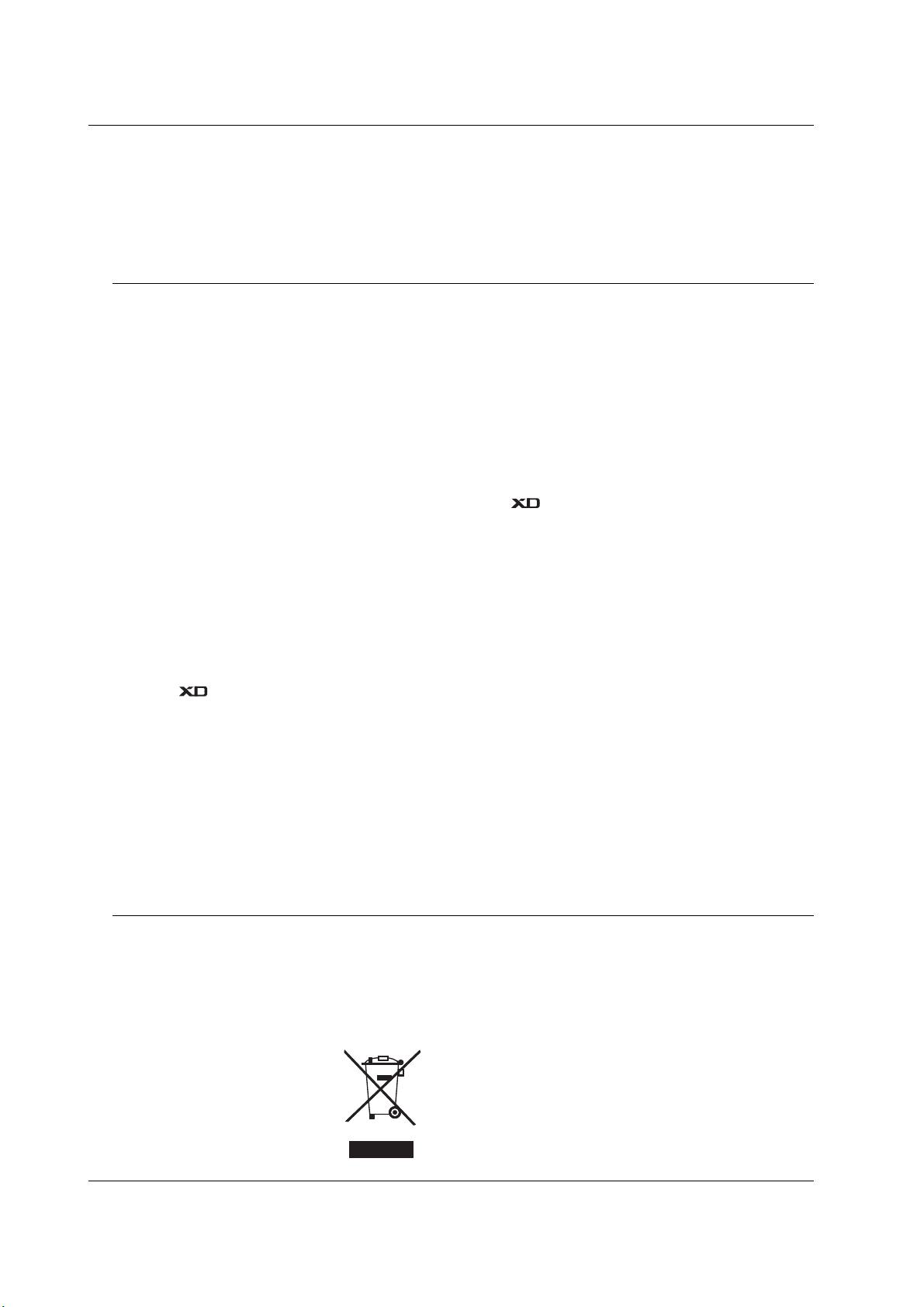
Disposal of your old appliance
1. When this crossed-out wheeled bin symbol is attached to a product it
means the product is covered by the European Directive 2002/96/EC.
2. All electrical and electronic products should be disposed of separately
from the municipal waste stream via designated collection facilities
appointed by the government or the local authorities.
3. The correct disposal of your old appliance will help prevent potential
negative consequences for the environment and human health.
4. For more detailed information about disposal of your old appliance,
please contact your city office, waste disposal service or the shop
where you purchased the product.

Owner’s Manual 5
Introduction
Introduction
Introduction
What is a Plasma Display ?
If voltage is inputted to gas in glass panels, ultraviolet rays is outputted and fused with a fluorescent substance. At this moment,
light is emitted. A Plasma Display is a next generation flat Display using this phenomenon.
160° - Wide angle range of vision
A Plasma Display provides more than 160° angle range of vision so that you can get a picture without distortion from any
direction.
Easy installation
A Plasma Display is much lighter and smaller than other same class products so that you can install the Plasma Display
at the desired place.
Big screen
The screen of a Plasma Display is 42" (50" or 60") so that you can get vivid experience as if you are in a theater.
Multimedia Plasma Display
A Plasma Display can be connected with a computer so that you can use it as a screen for conference, game, internet
and so on.
The explanation about coloured dots may be present on PDP screen
The PDP which is the display device of this product is composed of 0.9 to 2.2 million cells and a few cell defects can occur
in the manufacture of the PDP. Several coloured dots visible on the screen would be acceptable, in line with other PDP
manufacturers and would not mean that the PDP is faulty. We hope you will understand that the product which corresponds to this standard is regarded as acceptable. It means that it could not be changed or refunded.
We promise that we'll do our best to develop our technology to minimize the cell defects.
The explanation about noise of PDP (option)
In the same way that a fan is used in a PC to keep the CPU cool, the PDP is equipped with cooling fans to improve the
reliability of this product. Therefore, a certain level of noise could occur when the fan is operated. This noise doesn't have
any negative effect on its efficiency and liability and it's also determined to have no difficulty while using this product. The
noise from the fans is normal in the operation of this product. We hope you will understand that a certain level of noise is
acceptable. It means that it is not changeable nor refundable.
TO AVOID BURNING IMAGE INTO THE DISPLAY, DO NOT HAVE A STILL IMAGE ON SCREEN FOR
EXTENDED PERIOD OF TIME. IMAGE AFTER BURN WILL NOT BE COVERED UNDER WARRANTY
ie.Menus, Video games, Borders or LOGOS
WARNING
This is Class A product. In a domestic environment this product may cause radio interference in which
case the user may be required to take adequate measures.
WARNING
TO REDUCE THE RISK OF FIRE AND ELECTRIC SHOCK, DO NOT EXPOSE THIS PRODUCT TO
RAIN OR MOISTURE.

6 PLASMA MONITOR
Introduction
Remote Control Key Functions
Remote Control Key Functions
- When using the remote control aim it at the remote control sensor of the set.
- There maybe a defect in consecutive operation of remote control in a specified brightness according to this set.
• Open the battery compartment cover on the back side and insert
the batteries with correct polarity.
• Install two 1.5V alkaline batteries of AA type. Don’t mix used batteries with new batteries.
Installing Batteries
INPUT
RGB
HDMI
INDEX
HOLD
POSITION
C
O
M
P
O
N
E
N
T1
AV
IZ
E
COMPONENT2
MULTIMEDIA
POWER
S-VIDEO
INPUT
RGB
HDMI
INDEX
MIX
HOLD
MODE
POSITION
REVEAL
S-VID
E
O
2
AV1
S
IZ
E
T
IM
E
AV3
MENU
TEXT/
SPLIT
ZOOM
ARC
OK
VOL VOL
PSM
SSM
SLEEP
I/II
COMPONENT
POWER
AV2
MUTE
M
?
LIST/
Q.VIEW/
MULTIMEDIA
Selects the Component, RGB or HDMI
modes.
POWER
switches the set on from standby or off to
standby.
NUMBER buttons
LIST (option)
displays the programme table.
VCR BUTTONS
Controls a video cassette recorder.
PSM
Adjusts the factory preset picture according to the room.
ARC
changes the picture format.
SSM
To select the sound appropriate to your
viewing programme.
MUTE
Switches the sound on or off.
TEXT/*(option)
These buttons are used for teletext.
For further details, see the ‘Teletext’ section.
COLOURED BUTTONS :
These buttons are used for teletext.
INPUT
MENU
displays on screen menus one by one.
exits the current menu.
memorizes menu changes.
SLEEP
Sets the sleep timer.
SPLIT ZOOM
enlarge the screen with regular ration.
I/II
(option)
Selects the language during dual language
broadcast.
Selects the sound output.
Q.VIEW (option)
Returns to the previously viewed
programme.
Note : This function works only when
Favourite prog. is set to Off. Otherwise
each press of this button will select a stored
favourite programme.
DD/ EE
Selects a menu option.
FF/ GG
(Volume Up/Down)
Increases/decreases sound level.
Adjusts menu settings.
OK
accepts your selection or displays the
current mode.
Owner’s Manual 7
Introduction
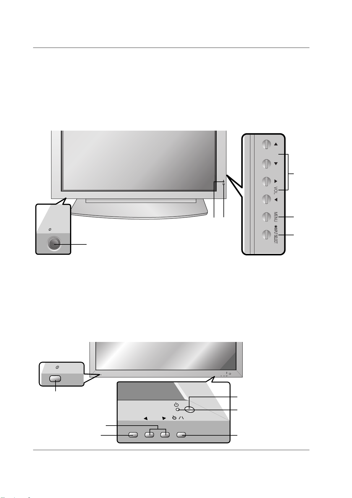
Location and Function of Controls
Location and Function of Controls
<Front Panel Controls>
60PZ9M/H series
42PM1M/H series / 50PM1M/H series
ON/OFF
- Shown is a simplified representation of the set.
- Here shown may be somewhat different from your set.
1. Main Power Button
2. Remote Control Sensor
3. Power Standby Indicator
Illuminates red in standby mode, Illuminates green when the
set is turned on
4. INPUT SELECT Button
5. MENU
Displays on screen menus one by one.
Exits the current menu.
Memorizes menu changes.
6.
DD/ EE
Selects a menu option.
FF/ GG
(Volume Up/Down)
Increases/decreases sound level.
Adjusts menu settings.
1
4
5
6
3
2
INPUT
SELECT
VOLUME
ON/OFF
ON/OFF
INPUT
SELECT
VOLUME
Main Power Button
INPUT SELECT Button
VOLUME (FF,GG) Buttons
Power Standby Indicator
Illuminates red in standby mode,
Illuminates green when the
Monitor is turned on
Remote Control Sensor
Sub power button
8 PLASMA MONITOR
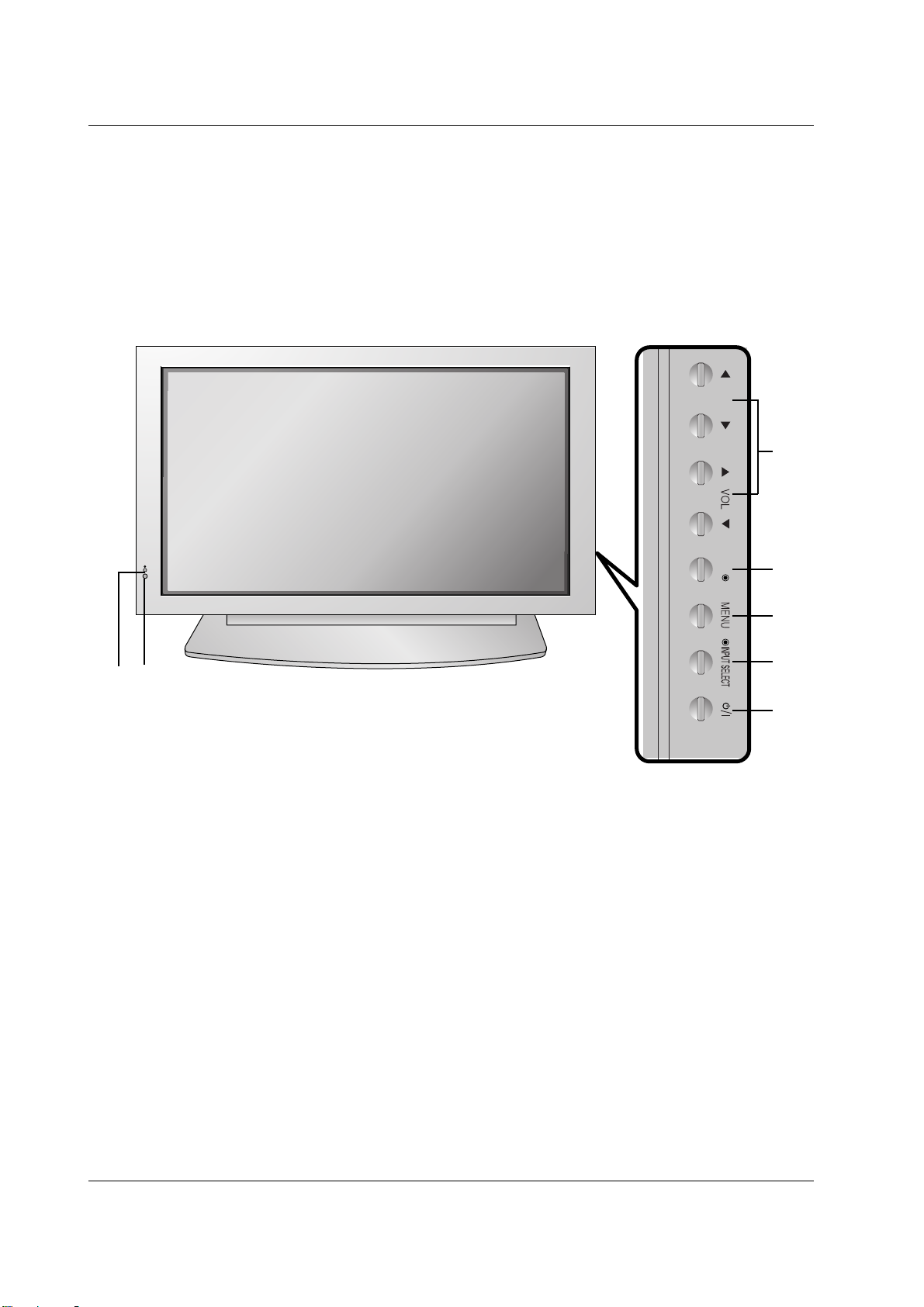
Introduction
Location and Function of Controls
Location and Function of Controls
<Front Panel Controls>
42PM3MV/H series
OK
1. Power Button
Switches the set on from standby or off to standby.
2. Remote Control Sensor
3. Power Standby Indicator
Illuminates red in standby mode, Illuminates green when
the set is turned on
4. INPUT SELECT Button
5. MENU
Displays on screen menus one by one.
Exits the current menu.
Memorizes menu changes.
6. OK
Accepts your selection or displays the current mode.
7.
DD/ EE
Selects a menu option.
FF/ GG
(Volume Up/Down)
Increases/decreases sound level.
Adjusts menu settings.
1
4
5
6
7
3
2
Owner’s Manual 9
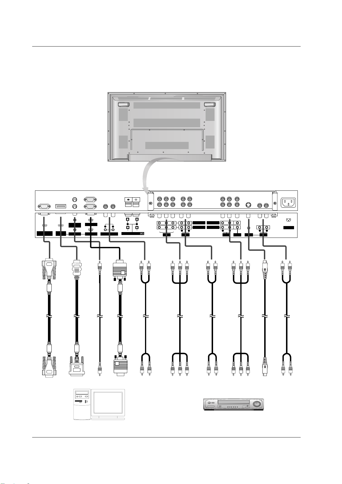
Introduction
<Back Panel>
AC INPUT
AUDIO INPUT RGB INPUT
RGB OUTPUT
RS-232C INPUT
(CONTROL/SERVICE)
REMOTE
CONTROL
S-VIDEO
YPBP
R
VIDEO
R
L
VARIABLE AUDIO OUT
AUDIO
R
L
EXTERNAL SPEAKER
HDMI/DVI
(VIDEO INPUT
R
L
AUDIO
R
L
AUDIO
R
L
AUDIO VIDEO
COMPONENT INPUT 2
COMPONENT INPUT 1
MONITOR OUPUT
A/V INPUT
(MONO) (MONO)
Connection to PC
Connection to AV equipment
10 PLASMA MONITOR
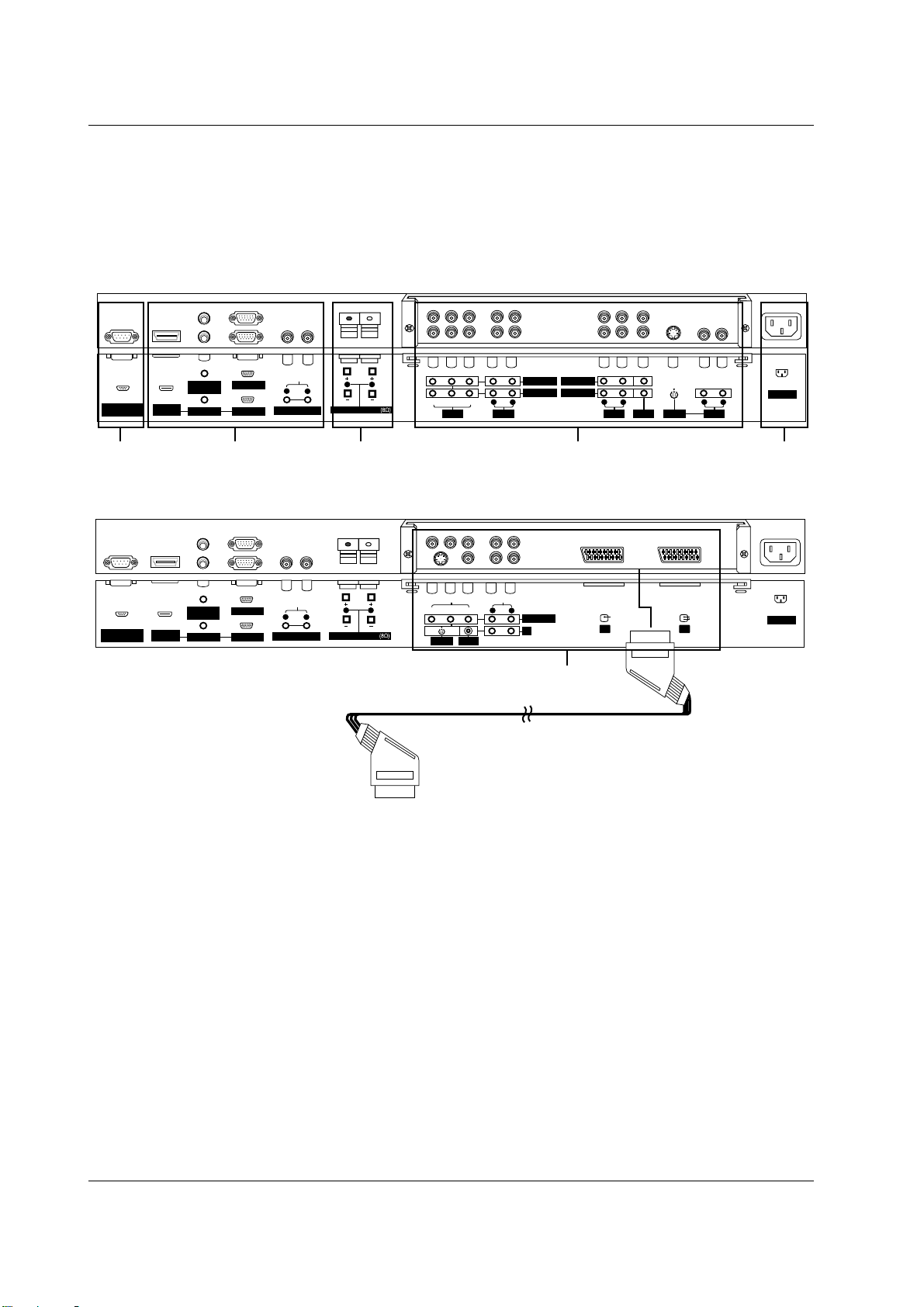
Introduction
<Back Panel>
AC INPUT
AUDIO INPUT RGB INPUT
RGB OUTPUT
RS-232C INPUT
(CONTROL/SERVICE)
REMOTE
CONTROL
YPBP
R
VIDEO
S-VIDEO
R
L
VARIABLE AUDIO OUT
AUDIO
R
L
EXTERNAL SPEAKER
HDMI/DVI
(VIDEO) INPUT
L
R
VIDEO
AUDIO
COMPONENT INPUT
AV3
(MONO)
AV1 AV2
AV1
RCA Type
Scart Type
4
AC INPUT
AUDIO INPUT RGB INPUT
RGB OUTPUT
RS-232C INPUT
(CONTROL/SERVICE)
REMOTE
CONTROL
S-VIDEO
YPBP
R
VIDEO
R
L
VARIABLE AUDIO OUT
AUDIO
R
L
EXTERNAL SPEAKER
HDMI/DVI
(VIDEO) INPUT
R
L
AUDIO
R
L
AUDIO
R
L
AUDIO VIDEO
COMPONENT INPUT 2
COMPONENT INPUT 1
MONITOR OUPUT
A/V INPUT
(MONO) (MONO)
1 2 345
1. RS-232C INPUT(CONTROL/SERVICE) PORT
Connect to the RS-232C port on a PC.
2. HDMI/DVI (VIDEO) / AUDIO INPUT / RGB INPUT SOCKETS
Connect the set output socket of the PERSONAL COMPUTER
to this socket.
Note: If you want to use RGB/DVI audio, we strongly recommend that you use the cable that has a core, or the EMI Filter
core along with separate cable.
RGB OUTPUT SOCKET
You can watch the RGB signal on another set, connect RGB
OUTPUT to another set’s PC input port.
REMOTE CONTROL
VARIABLE AUDIO OUTPUT
3. EXTERNAL SPEAKER OUTPUT (8 ohm)
Connect to optional external speaker(s).
* For further information, refer to ‘Speaker & Speaker Stand’
manual.
4. COMPONENT / AUDIO INPUT SOCKETS
S-VIDEO / AUDIO (L/MONO) INPUT SOCKETS
VIDEO / AUDIO (L/MONO) INPUT SOCKETS
EURO SCART SOCKET
Connect the euro scart socket of the VCR to these sockets.
Note:
a. If you want to use the EURO scart cable, you have to use
the signal shielded Euro scart cable.
b. If you want to use your external hi-fi stereo system, turn off
the internal speakers of the set.
c. If the S-VIDEO(Y/C) signal is received through the Euro scart
socket 2 (AV 2), you must change to the S-Video 2 (Y/C) mode.
5. POWER CORD SOCKET
This set operates on an AC power. The voltage is indicated on
the Specifications page. Never attempt to operate the set on
DC power.
Location and Function of Controls
Location and Function of Controls
Owner’s Manual 11
Installation
External Equipment V
External Equipment V
iewing Setups
iewing Setups
Watching VCR (When the Interface board is installed.)
- When connecting the set with external equipments, match the colours of connecting ports (Video - yellow, Audio(L) - white,
Audio(R) -red).
- Connect the VIDEO INPUT socket(yellow) to the VIDEO INPUT socket of the set.
- If you have a mono VCR, connect the audio cable from the VCR to the AUDIO(L/MONO) input of the set.
- If you connect an S-VIDEO VCR to the S-VIDEO input, the picture quality is improved; compared to connecting a regular
VCR to the Video input.
- Or, connect the Euro scart socket of the VCR to the Euro scart socket of the set.
Avoid having a fixed image remain on the screen for a long period of time. Typically a frozen still picture from a VCR, 4:3
picture format or if a CH label is present; the fixed image may remain visible on the screen.
Use the orbiter function to avoid having a fixed image. (Refer to p.24)
1. Press INPUT button on the remote control and select AV , S-Video or (AV 1 , AV 2 , S-Video2 or AV 3 ).
(If both S-VIDEO and VIDEO sockets have been connected to the S-VHS VCR simultaneously, only the S-VIDEO can be
received.)
2. Insert a video tape into the VCR and press the PLAY button on the VCR. (See VCR owner’s manual)
Watching external AV source
(When the Interface board is installed.)
- When connecting the set with external equipments, match the colours of connecting ports.
- Or, connect the Euro scart socket of the VCR to the Euro scart socket of the set.
1. Press INPUT button on the remote control of the set to select
AV , S-Video or (AV 1 , AV 2 , S-Video2 or AV 3 ).
2. Operate the corresponding external equipment. (See external equipment operating guide.)
Watching Cable TV
(When the Interface board is installed.)
- After subscribing to a cable TV service from a local provider and installing a converter, you can watch cable TV programming.
This set cannot display TV programming without a TV tuner device or cable TV converter box connected to the set.
1. Press INPUT button on the remote control and select
AV , S-Video or (AV 1 , AV 2 , S-Video2 or AV 3 ).
2. Tune to cable service provided channels using the cable box.
• Component Input ports
You can get better picture quality if you connect DVD player with component input ports
as below.
Component ports of the set
Y PB
PR
Video output ports
of DVD player
Y
Y
Y
Y
Pb
B-Y
Cb
PB
Pr
R-Y
Cr
PR
Watching DVD
(When the Interface board is installed.)
How to connect
- Connect DVD video inputs to Y, P
B
, PRof COMPONENT (DVD
INPUT) and audio inputs to Audio sockets of AUDIO INPUT.
- Or, connect the Euro scart socket of the VCR to the Euro scart
socket of the set.
How to use
1. Press INPUT or MULTIMEDIA button on the remote control of the
set to select Component or (Component1 or Component2).
2. Try this after turning on the DVD player.
(Refer to the DVD player's manual for operating instructions.)
 Loading...