

LG 42PJ350 Schematic

Training Manual
Advanced Single Scan Troubleshooting
2
h
0
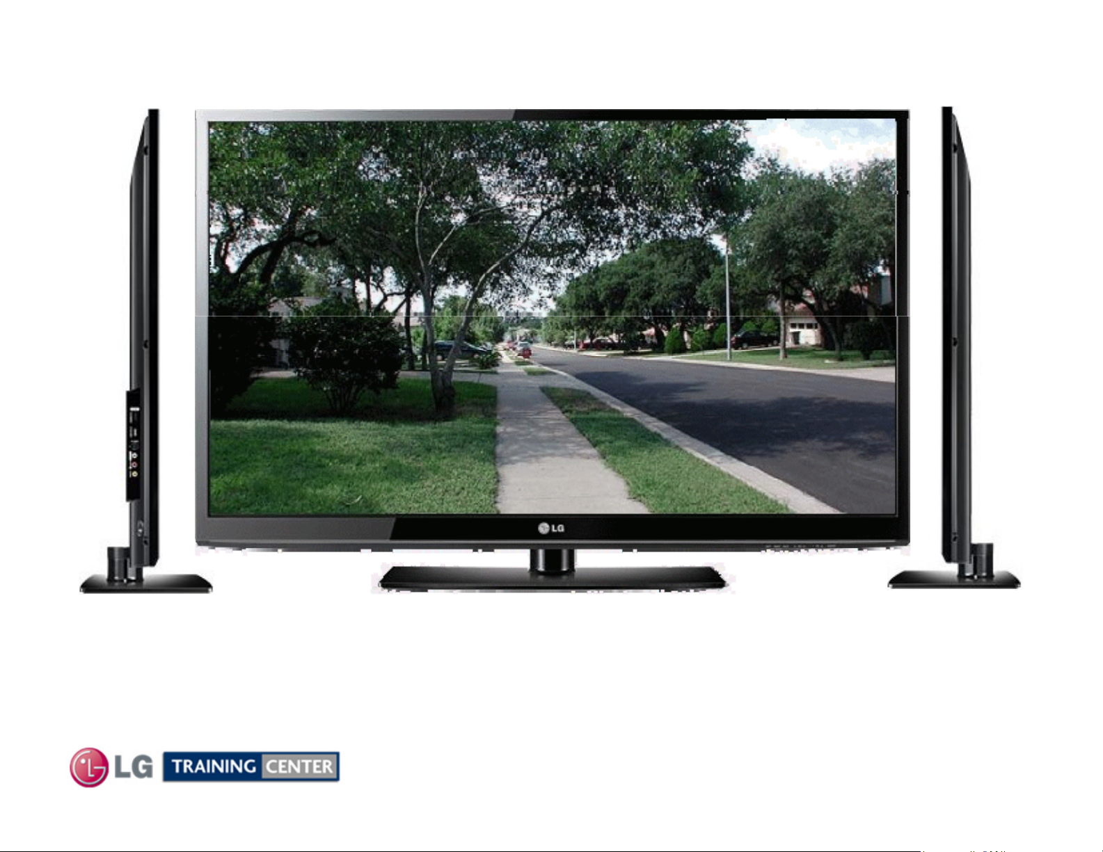
42PJ350 Plasma Display42PJ350 Plasma Display
42" Class HD 720p Plasma TV
(41.6" diagonally)
Published August 1
t
, 201
Updated February 3rd, 2011

OUTLINEOUTLINE
X Drive Boards (2)
Overview of Topics to be Discussed
Preliminary:
Contact Information, Preliminary Matters, Specifications,
Plasma Overview, General Troubleshooting Steps,
Disassembly Instructions, Voltage and Signal Distribution
No Main Power Switch (Vacation Switch).
Troubleshooting:
Circuit Board Operation, Troubleshooting and Alignment of :
• Switch Mode Power Supply
No VS On command input to SMPS
• Y-SUS Board Delivers Logic Signals and FG5V to Y-Drive board.
• Y-Drive Board
• Z-SUS Output Board (Also uses one Z-SUB board for bottom panel connector)
• Control Board
•
• Main Board
• Interconnect Diagram:
11X17 Foldout Section used as a quick reference sheet.
2
August 2010 42PJ350 Plasma

Overview of Topics to be DiscussedOverview of Topics to be Discussed
42PJ350 Plasma Display
yqp
yy
The first section will cover Contact Information and Important Safety Precautions
for the Customers Safety as well as the Technician and the Equipment.
Basic Troubleshooting Techniques which can save time and money sometimes
can be overlooked. These techniques will also be presented.
The next section will get the Technician familiar with the Disassembly, Identification
and Layout of the Plasma Display Panel.
At the end of this Section the Technician should be able to Identify the Circuit
Boards and have the ability and knowledge necessary to safely remove and
replace any Circuit Board or Assembly.
3
August 2010 42PJ350 Plasma
LG Contact InformationLG Contact Information
T
(800) 84
Customer Service Website
http://www.us.lgservice.com
g
g
pg
and Screen Marks
47LG90, 47LH85, 42LE5500, 47LE8500
Also available on the Plasma Page:
LG Electronics Alabama, Inc
Customer Service (and Part Sales) (800) 243-0000
echnical Support (and Part Sales)
7-7597
USA Website (GSFS) http://gsfs-america.lge.com
Knowledgebase Website http://lgtechassist.com
LG Web Trainin
https://lge.webex.com
LG CS Academy http://ln.lge.com/ilearn
LCD-DV:
PLASMA:
32LG40, 32LH30, 37LH55, 42LG60, 42LG70, 42LH20, 42LH40, 42LH50, 42LH90, 42SL80,
42PG20, 42PJ350, 42PQ20, 42PQ30, 50PG20, 50PJ350, 50PK250, 50PK750, 50PS80,
50PS60, 60PK750, 60PS11, 60PS60, 60PS80
New: 2010 Models Software
Downloads Technical Assistance
Presentations with Audio/Video
http://136.166.4.200
PDP Panel Alignment Handbook, Schematics with Bookmarks
Plasma Control Board ROM Update (Jig required)
Published August 2010 by LG Technical Support and Training
New Training Materials on New Training Materials on
the Learning Academy sitethe Learning Academy site
.
201 James Record Road, Huntsville, AL, 35813.
4
August 2010 42PJ350 Plasma

Preliminary Matters (The Fine Print)Preliminary Matters (The Fine Print)
IMPORTANT SAFETY NOTICEIMPORTANT SAFETY NOTICE
to repair a major Product, personal injury and property damage can result. The manufacturer or
modifications will not only void the warranty, but may lead to property damage or user injury
CAUTIONCAUTION
necessary checks. Also be aware that many household products present a weight hazard
The information in this training manual is intended for use by persons possessing an adequate
background in electrical equipment, electronic devices, and mechanical systems. In any attempt
seller maintains no liability for the interpretation of this information, nor can it assume any
liability in conjunction with its use. When servicing this product, under no circumstances should
the original design be modified or altered without permission from LG Electronics. Unauthorized
.
If wires, screws, clips, straps, nuts, or washers used to complete a ground path are removed for
service, they must be returned to their original positions and properly fastened.
To avoid personal injury, disconnect the power before servicing this product. If electrical power is
required for diagnosis or test purposes, disconnect the power immediately after performing the
At least two people should be involved in the installation or servicing of such devices.
Failure to consider the weight of an product could result in physical injury.
5
August 2010 42PJ350 Plasma
.

ESD NoticeESD Notice
removing a replacement part from its package, touch the anti
static bag to a ground connection point or
g
gp p g
radio or television reception, which can be determined by turning the equipment off and on, the user is
Today’s sophisticated electronics are electrostatic discharge (ESD) sensitive. ESD can weaken or damage
the electronics in a manner that renders them inoperative or reduces the time until their next failure.
Connect an ESD wrist strap to a ground connection point or unpainted metal in the product. Alternatively,
you can touch your finger repeatedly to a ground connection point or unpainted metal in the product. Before
unpainted metal in the product. Handle the electronic control
repackaging a failed electronic control assembly in an anti-static bag, observe these same precautions.
(Electrostatic Static Discharge)(Electrostatic Static Discharge)
assembly by its edges only. When
Regulatory InformationRegulatory Information
This equipment has been tested and found to comply with the limits for a Class B digital device, pursuant to
Part 15 of the FCC Rules. These limits are desi
interference when the equipment is operated in a residential installation. This equipment generates, uses,
and can radiate radio frequency energy, and, if not installed and used in accordance with the instruction
manual, may cause harmful interference to radio communications. However, there is no guarantee that
interference will not occur in a particular installation. If this equipment does cause harmful interference to
encouraged to try to correct the interference by one or more of the following measures: Reorient or relocate
the receiving antenna; Increase the separation between the equipment and the receiver; Connect the
equipment to an outlet on a different circuit than that to which the receiver is connected; or consult the
dealer or an experienced radio/TV technician for help.
ned to provide reasonable protection against harmful
6
August 2010 42PJ350 Plasma

Safety and Handling, Checking PointsSafety and Handling, Checking Points
pgp
Safety & Handling Regulations
1. Approximately 10 minute pre-run time is required before any adjustments are performed.
2. Refer to the Voltage Sticker inside the Panel when making adjustments on the Power Supply, Y-SUS and Z-SUS Boards.
3. Always adjust to the specified voltage level (+/- ½ volt) unless otherwise specified.
4. Be cautious of electric shock from the PDP module since the PDP module uses high voltage, check that the Power Supply
and Drive Circuits are completely discharged because of residual current stored before Circuit Board removal.
4. C-MOS circuits are used extensively for processing the Drive Signals and should be protected from static electricity.
5. The PDP Module must be carried by two people. Always carry vertical NOT horizontal.
6. The Plasma television should be transported vertically NOT horizontally.
7. Exercise care when making voltage and waveform checks to prevent costly short circuits from damaging the unit.
8. Be cautious of lost screws and other metal objects to prevent a possible short in the circuitry.
9. New Panels and Frames are much thinner than previous models. Be Careful with flexing these panels. Be careful
with lifting Panels from a horizontal position. Damage to the Frame mounts or panel can occur.
10. New Plasma models have much thinner cabinet assemblies and mounts.
Be extremely careful when moving the set around as damage can occur.
Checking Points to be Considered
1. Check the appearance of the Replacement Panel and Circuit Boards for both physical damage and part number accuracy.
2. Check the model label. Verify model names and board model matches.
3. Check details of defective condition and history. Example: Y-SUS or Y-Drive Board Failure, Mal-discharge on screen, etc.
7
August 2010 42PJ350 Plasma
Basic Troubleshooting StepsBasic Troubleshooting Steps
Define, Localize, Isolate and Correct
p
ppp
A
ygyp g
p
p
g
gg ppyy g
y
yj y y
• Define Look at the symptom carefully and determine what circuits could be causing the
failure. Use your senses Sight, Smell, Touch and Hearing. Look for burned parts and check
for
give off a distinct odor. Frequency of power supplies will change with the load, or listen for
relay closing etc. Observation of the front Power LEDs may give some clues.
• Localize
and after giving a thorough examination using your senses the first check should always be
the DC Supply Voltages to those circuits under test. Always confirm the supplies are not only
the proper level but be sure they are noise free. If the supplies are missing check the
resistance for
• Isolate To further isolate the failure, check for the proper waveforms with the
Oscilloscope to make a final determination of the failure. Look for correct Amplitude Phasing
and Timin
“glitches” or “road bumps” will be an indication of an imminent failure.
• Correct
ossible overheated components. Capacitors will sometimes leak dielectric material and
fter carefully checking the symptom and determining the circuits to be checked
ossible short circuits.
of the signals also check for the proper Duty Cycle of the signals. Sometimes
The final step is to correct the problem. Be careful of ESD and make sure to
check the DC Supplies for proper levels. Make all necessar
perform a Safety AC Leakage Test before returning the product back to the Customer.
8
adjustments and lastly always
August 2010 42PJ350 Plasma
42PJ350 PRODUCT INFORMATION SECTION42PJ350 PRODUCT INFORMATION SECTION
This section of the manual will discuss the specifications of the
42PJ350 Advanced Single Scan Plasma Display Television.
9
August 2010 42PJ350 Plasma
42PJ350 Specifications42PJ350 Specifications
)
(g)
Intelli
Clear Voice II
Infinite S
d
42" Class (41.6" diagonal
• 600Hz Sub Field Driving
• High Definition Resolution
1080P PLASMA HDTV
• 3M:1 Dynamic Contrast Ratio
• TruSlim Frame
• Picture Wizard II (Easy Picture Calibration)
• Smart Energy Saving
•
• Dual XD™ Engine
• AV Mode (Cinema, Sports, Game)
•
• ISFccc® Ready
• 24P Real Cinema
• USB 2.0 (JPEG, MP3)
• 3 HDMI™ 1.3 Inputs
• SIMPLINK™ Connectivity
gent Sensor
For Full Specifications
See the Specification Sheet
• Dolby® Digital 5.1 Decoder
•
oun
10
August 2010 42PJ350 Plasma

42PJ350 Logo Familiarization Page 1 of 342PJ350 Logo Familiarization Page 1 of 3
600Hz Sub Field Firing:
At l
thick th
Slim F
ithout
Capture every moment. Tired of streaky action or unclear plays during the
game? See sports, fast action and video games like never before. The 600Hz
refresh rate virtually eliminates motion blur.
3.000,000 : 1 Contrast Ratio
Stunning detail. No more worrying about dark scenes or dull colors.
The Mega Contrast ratio of 3,000,000:1 delivers more stunning colors and
deeper blacks than you can imagine.
TruSlim Design:
ess than 1"
compromising screen size.
e new Tru
rame trims away distraction w
USB 2.0:
View videos and photos and listen to music on your TV through USB 2.0.
August 2010 42PJ350 Plasma
11
42PJ350 Logo Familiarization Page 2 of 342PJ350 Logo Familiarization Page 2 of 3
HD RESOLUTION 720P HD R
1365 (H)
768 (V)
y
yp
p
TAKE IT TO THE EDGE newly introduces Invisible Speaker system
esolution Pixels:
See and experience more. Pictures are sharper.
Colors are more vibrant. Entertainment is more real.
Everything looks better on an HDTV.
HDMI (1.3 Deep Color) Digital multi-connectivity
HDMI (1.3 Deep color) provides a wider bandwidth (340MHz,
10.2Gbps) than that of HDMI 1.2, delivering a broader range of colors,
and also drasticall
Invisible Speaker
Personally tuned by Mr. Mark Levinson for LG
guaranteeing first class audio quality personally tuned by Mr. Mark
Levinson, world renowned as an audio authority. It provides Full Sweet
Spot and realistic sound equal to that of theaters with its Invisible
Speaker.
improves the data-transmission speed.
‘
×
’
,
Dual XD Engine
Realizing optimal quality for all images
One XD Engine optimizes the images from RF signals as another XD
Engine optimizes them from External inputs. Dual XD Engine presents
images with optimal quality two times higher than those of previous
models.
12
August 2010 42PJ350 Plasma

42PJ350 Logo Familiarization Page 3 of 342PJ350 Logo Familiarization Page 3 of 3
,p ,
noise swells
The default factory setting complies with the Energy Star requirements
S
the same price as less
odels
ess energy means you pay less on your energy
t e sa e p ce as ess
e c e t ode s ess e e gy ea s you pay ess o you e e gy
AV Mode "One click" Cinema, Sports, Game mode.
AV Mode is three preset picture and audio settings. It allows the viewer
to quickly switch between common settings. It includes Cinema, Sports,
and Game Modes.
Clear Voice Clearer dialogue sound
Automatically enhances and amplifies the sound of the human voice
frequency range to provide high-quality dialogue when background
.
Save Energy, Save Money
It reduces the plasma display’s power consumption.
and is adjusted to the comfortable level to be viewed at home.
(Turns on Intelligent Sensor).
ave Energy, Save Money
Home electronic products use energy when they're off to power features like clock
displays and remote controls. Those that have earned the ENERGY STAR use as much
as 60% less energy to perform these functions, while providing the same performance at
-efficient m
bill. Draws less than 1 Watt in stand by.
. L
13
August 2010 42PJ350 Plasma
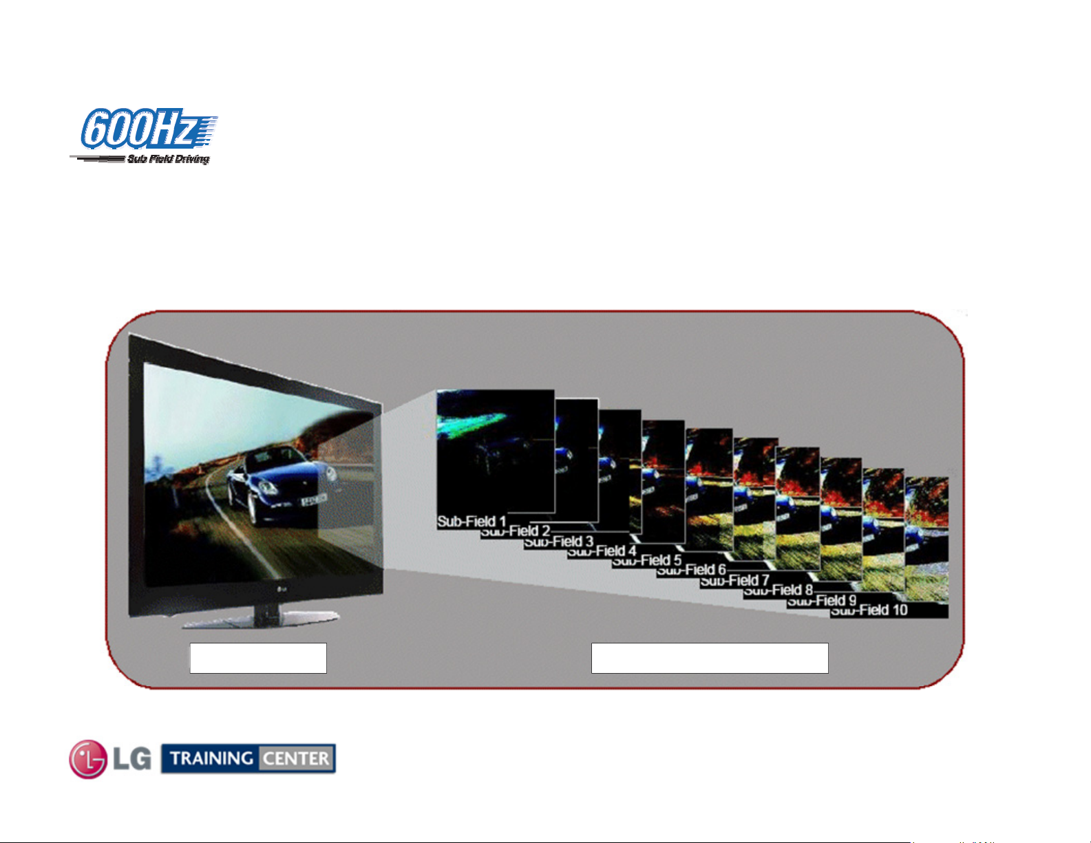
600Hz Sub Field Driving600Hz Sub Field Driving
(600 Hz Sub Field Driving)
• 600 Hz Sub Field Driving is achieved by using 10 sub-fields per frame process
(vs. Comp. 8 sub-field/frame)
• No smeared images during fast motion scenes
Original Image 10 Sub Fields Per Frame
Sub Field firing occurs using wall charge and polarity differences between Y-SUS and Z-SUS signals.
14
August 2010 42PJ350 Plasma
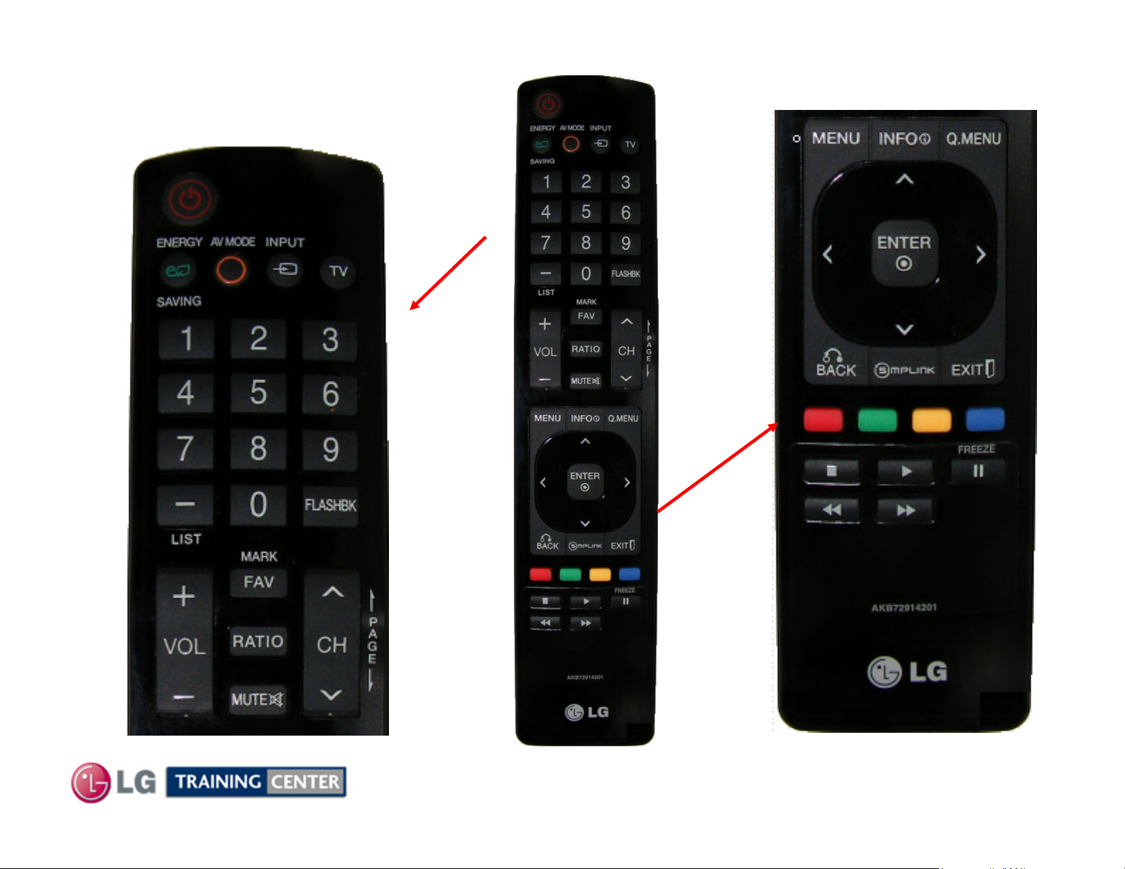
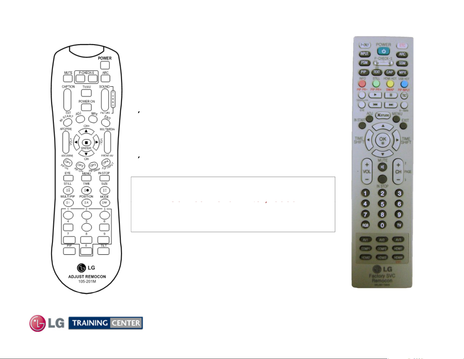
42PJ350 Remote Control42PJ350 Remote Control
p/n AKB72914201
TOP PORTION
BOTTOM PORTION
15
August 2010 42PJ350 Plasma
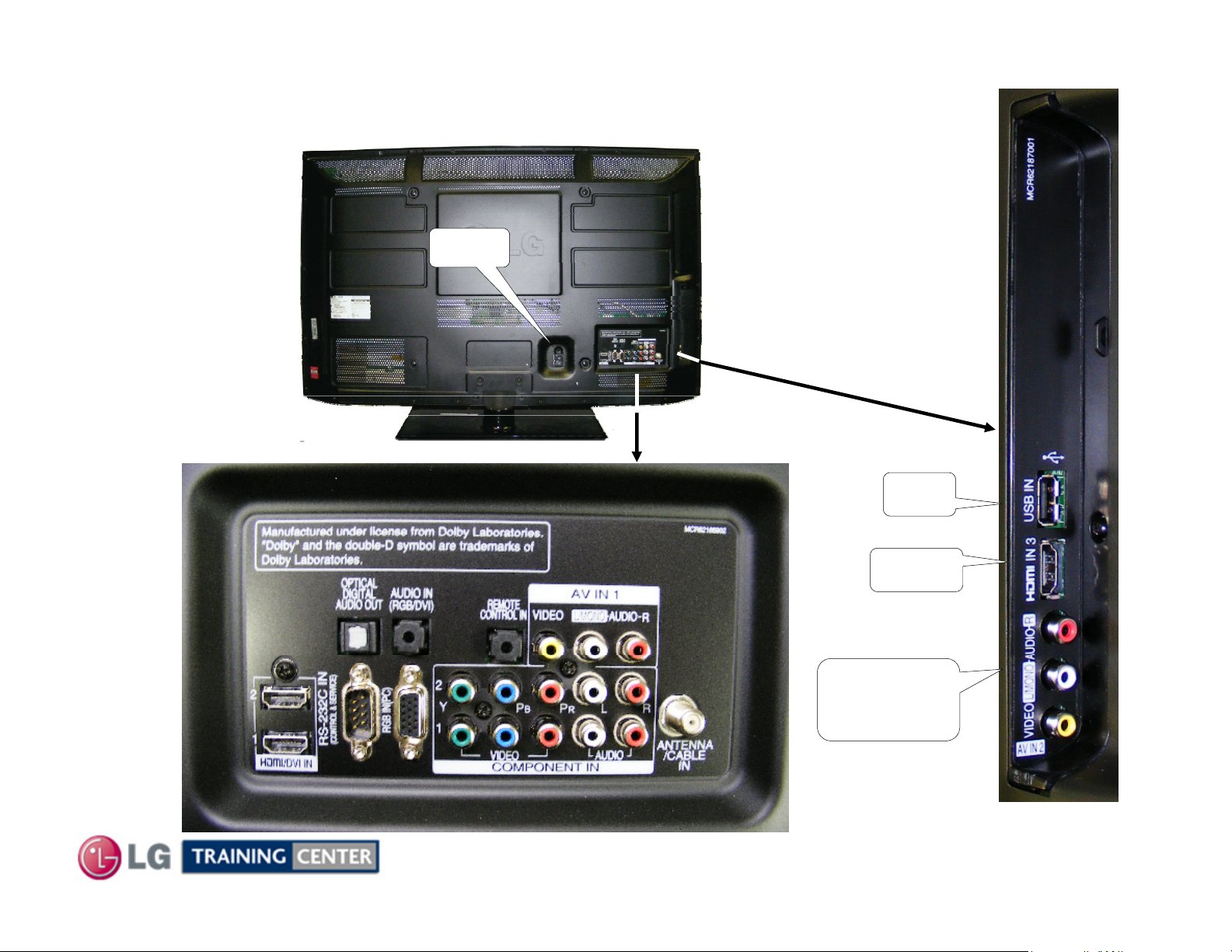
42PJ350 Rear and Side Input Jacks42PJ350 Rear and Side Input Jacks
Upgrades
REAR
INPUTS
AC In
USB for Music, Photos
and Software
SIDE
INPUTS
USB
HDMI 3
Composite
Video/Audio
16
August 2010 42PJ350 Plasma
Accessing the Service MenuAccessing the Service Menu
)
)
)
)
Se
0000
Se ce e u te ;
0000
To access the Service Menu.
1
You must have either Service Remote.
p/n 105-201M or p/n MKJ39170828
2) Press “In-Start”
3) A Password screen appears.
4
Enter the Password.
Note: A Password is required to enter the
rvice Menu. Enter;
105-201M
Note: If 0000 does not work use 0413.
17
August 2010 42PJ350 Plasma
MKJ39170828
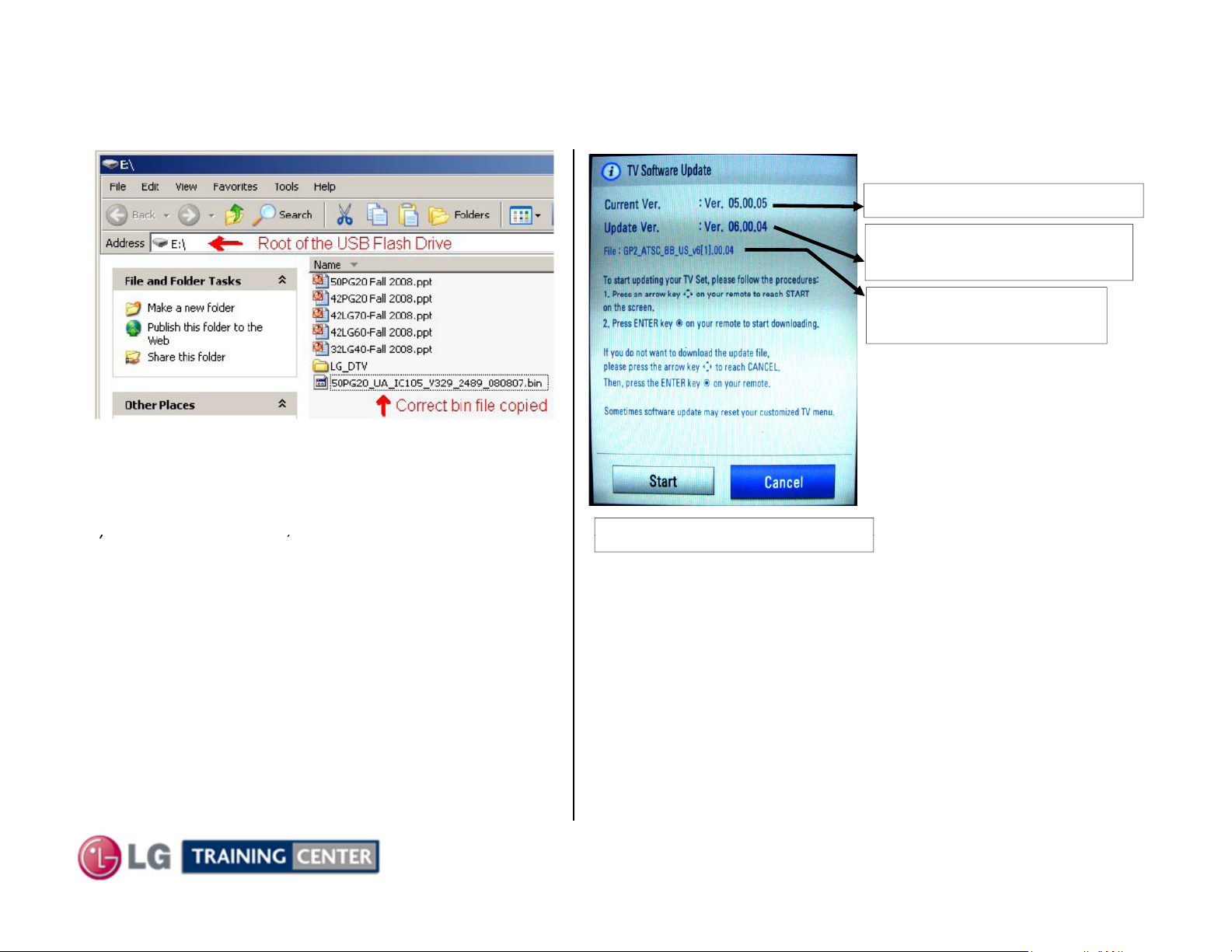
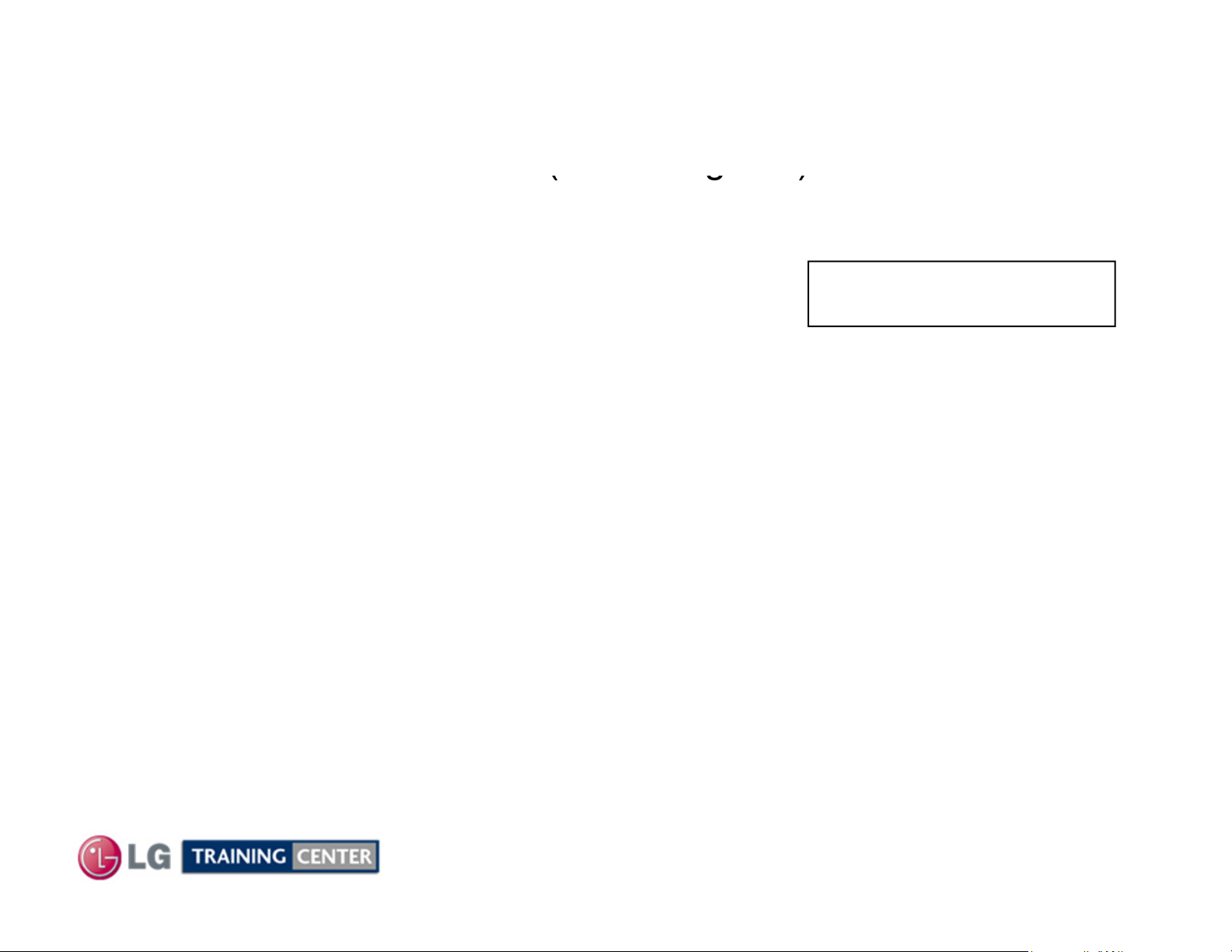
Generic Plasma USB Automatic Software Download InstructionsGeneric Plasma USB Automatic Software Download Instructions
)
),
Highlight Start Press Select
6) You can see the download progress Bar
1) Download the Software File.
2) Copy new software (xxx.bin) into the root of the
Jump Drive. Make sure you have the correct
software file.
With TV turned on, insert USB flash drive.
3
4) You can see the message
“TV Software Upgrade” (See figure on right)
5) Cursor left and highlight "START" Button and
push “Enter” button using the remote control.
.
7) Do not unplug until unit has automatically
restarted.
8) When download is completed, you will see
“COMPLETE”.
9) Your TV will be restarted automatically.
* CAUTION:
Do not remove AC power or the USB Flash Drive.
Do not turn off Power, during the upgrade
process.
Software Files are available from
GCSC or GSFS.com
Currently Installed Version
Software Version found on
the USB Flash Drive
File found on the USB
Flash Drive
18
August 2010 42PJ350 Plasma
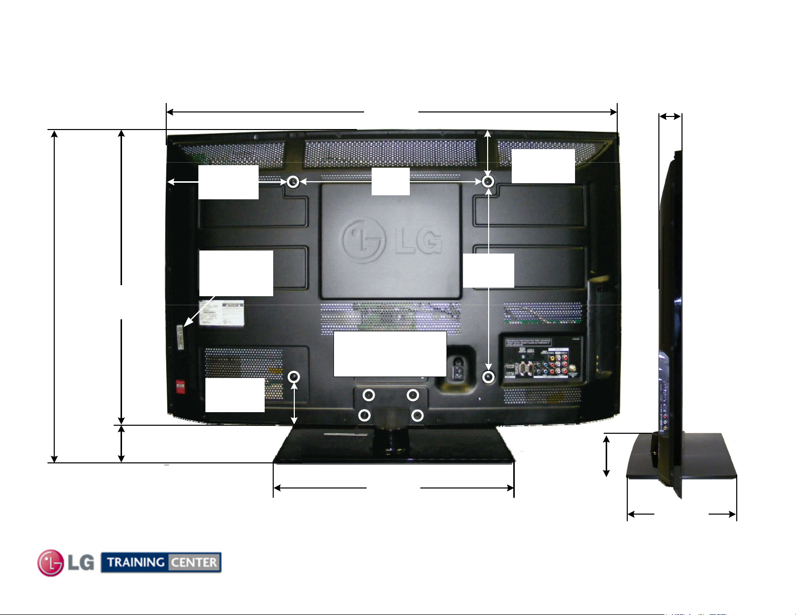
42PJ350 Dimensions
Power:
285W (Typical)
0.2W (Stand-By)
27-1/8"
688.34mm
24-5/6"
617.22mm
There must be at least 4 inches of Clearance on all sides
11-7/16”
290mm
Model No.
Serial No.
Label
38-7/8"
955.06mm
15-3/4"
400mm
Remove 4 screws
to remove stand
for wall mount
2-3/16"
55.88mm
4-9/16”
116mm
15-3/4"
400mm
2-13/16"
71.43mm
Weight:
3-15/16”
100mm
47.6 lbs with Stand
41.1 lbs without Stand
18-3/4"
476.25mm
19
2-3/16"
56mm
10-3/16"
259.08mm
August 2010 42PJ350 Plasma
DISASSEMBLY SECTIONDISASSEMBLY SECTION
Upon completion of this section the Technician will have a better
This section of the manual will discuss Disassembly, Layout and Circuit
Board Identification, of the 42PJ350 Advanced Single Scan Plasma Display Panel.
understanding of the disassembly procedures, the layout of the printed
circuit boards and be able to identify each board.
20
August 2010 42PJ350 Plasma
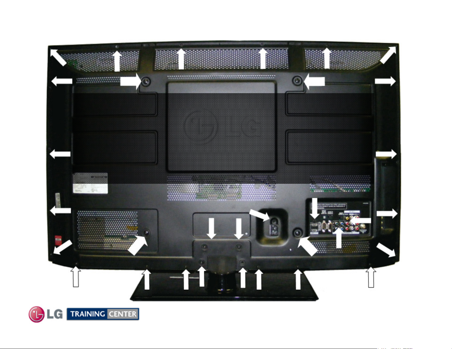
Removing the Back CoverRemoving the Back Cover
PAY CLOSE ATTENTION TO THE TYPE, SIZE AND LENGTH
To remove the back cover, remove the 32 screws
(The Stand does not need to be removed).
Of the screws when replacing the back cover.
Improper type can damage the front.
Indicated by the arrows.
21
August 2010 42PJ350 Plasma
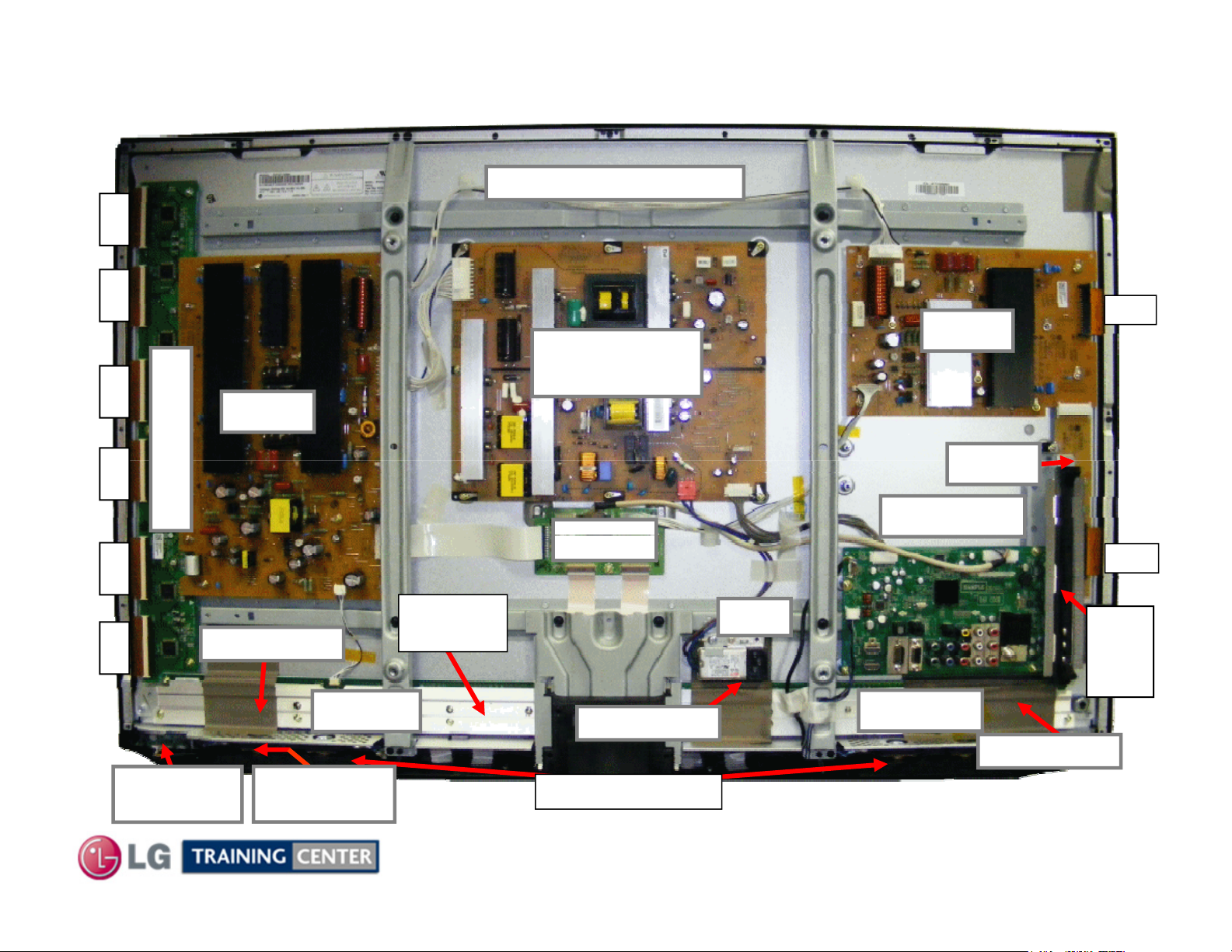
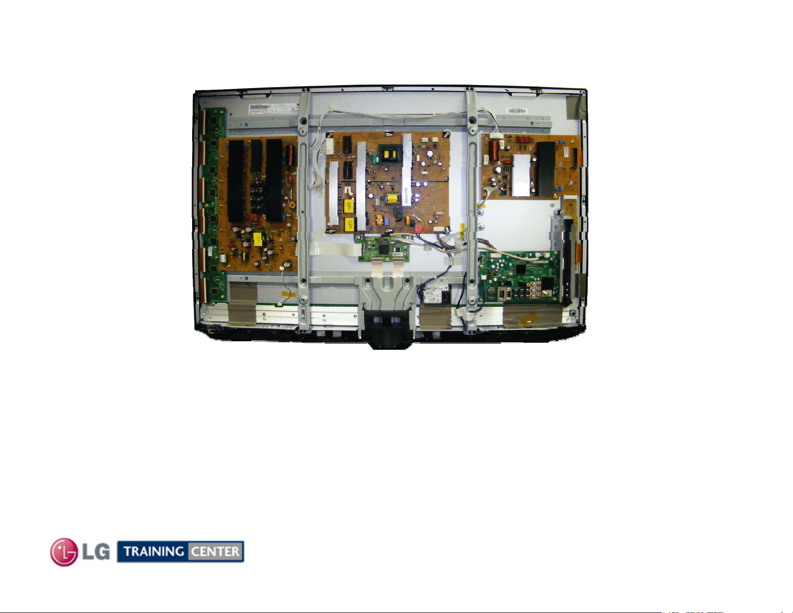
Circuit Board LayoutCircuit Board Layout Identifying the Circuit BoardsIdentifying the Circuit Boards
P
P
i
Y
SUS
i
C
Control
C
IR/LED
Soft T
h
Panel Voltage and Panel ID Label
FPC F
C FPC
Y-Dr
Power Supply
(SMPS)
FPC
Z-SUS
ve Board
FPC
-
Z-SUB
Main Board
FPC FP
Board
Conductive Tape
Keypad
Left “X”
ouc
TCP
Heat Sink
Conductive Tape
Invisible Speakers
AC In
Right “X”
Conductive Tape
FPC
Side
Input
(part of
main)
22
August 2010 42PJ350 Plasma
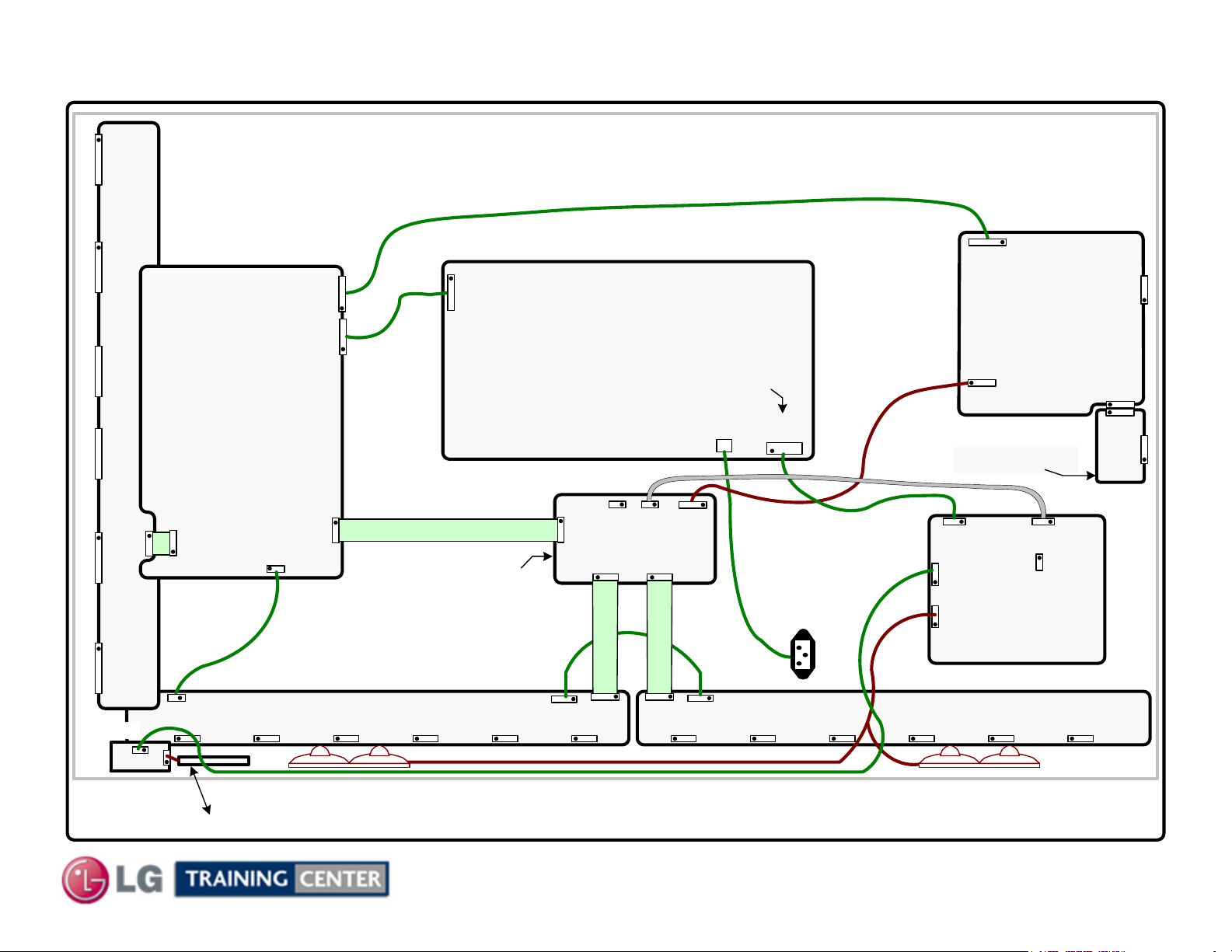
42PJ350 Connector Identification Diagram
42PJ350 Connector Identification Diagram
PANEL
p/n: EAJ60716204 (PDP42T10000.ADLGB)
P201P202P303
Y-DRIVE
p/n: EAJ60716215 (PDP42T10000.ADLGB)
Board
p/n: EBR63633601
P206
P811
SMPS
P201
POWER SUPPLY
Board
Y-SUS
p/n: EAY60912401
Board
p/n: EBR63038301
P204P205P206
P163
P101
P101
P211P106
P209
p/n: EBR63632301
n/c
P121
CONTROL
Board
P161
Top row Odd
Back row Even
SC101
LN
P102
P162
P813
LVDS
P2
Z-SUS
Board
p/n: EBR63038801
P1
p/n: EBR63634601
Z-SUB Board
P301
P704
P703
MAIN
P801
Board
P900
n/c
P4
P3
P2
P1
P233
P100
P101
FRONT IR
p/n: EBR65007704
AC
In
LEFT X Board
P201 P202 P203 P204 P205 P206 P301 P302 P303 P304 P305 P306
Speakers (Front Right)
Front “Soft Switch” Key Pad
p/n: EBR63628801
P232P211
P331 P311
23
p/n: EBR63628701
p/n: EAB60962801p/n: EAB60962801
August 2010 42PJ350 Plasma
Speakers (Front Left)
p/n: EBT60953602
RIGHT X Board
Disassembly Procedure for Circuit Board RemovalDisassembly Procedure for Circuit Board Removal
Switch Mode P
l
Label. Also, re
confirm VSC
and Z
Bias as well
Confirm VSC,
and Z
bias as well.
y
ygp g p
The b
lifted slightly t
“Ch
Note: 1) Remember to be cautious of ESD as some semiconductors are CMOS and prone to static failure.
ower Supply Board Remova
Disconnect the following connectors: P811, P813 and SC101.
Remove the 8 screws holding the SMPS in place.
Remove the board. When replacing, be sure to readjust the Va/Vs voltages in accordance with the Panel
-
Y-SUS Board Removal
Remove the Left Vertical Brace. 4 screws, 2 metal tap and 2 plastic tap.
Disconnect the following connectors: P201, P203, P206, P211 and Ribbon Cable P101.
To remove P101, lift up on the locking mechanism and pull the ribbon cable out.
Remove the 16 screws holding the Y-SUS in place. Do not run the set with P211removed.
Remove the Y-SUS board. When replacing, be sure to readjust the Va/Vs voltages in accordance with the
Panel Label.
-
Vy
Y-Drive Board Removal
-
, -Vy
-
Note: The Y-SUS does not come with the connectors
.
Note: The Y-SUS does not come with the connector to
the Lower Y-Drive
between the Y-SUS and Y-Drive
Board Standoff
Disconnect P101~P106 Connectors to the Panel
Remove P106 b
Do not run the set with P106 connector removed.
Remove the 7 screws holding the Y-Drive board in place.
Lift up slightly, the slide to the left. Remove the Y-Drive Board.
Note: Y-SUS, Z-SUS and Y-Drive boards are mounted on board stand-offs that have a small collar.
like material) that act as shock absorbers. They may make the board stick when removing.
lifting up on the locking mechanism and pull the ribbon cable out.
oard must be
o clear these collars. Behind each board are
24
Collar
ocolate” (dense rubber
August 2010 42PJ350 Plasma
Disassembly Procedure for Circuit Board Removal (2)Disassembly Procedure for Circuit Board Removal (2)
Control B
l
KEY PAD:
Z-SUS Board Removal
Disconnect the following connectors: P1 and P2, then P4 by pulling out the locking mechanism and pulling out the
FPC to the panel. Note, slide a thin object (top side) between ribbon and connector to remove.
Remove the 9 screws holding the board in place.
Lift up slightly to clear the screw stand-offs and pull the Z-SUS upward to unseat P3/P2 from the Z-SUB board and
remove the Z-SUS board.
When replacing, be sure to readjust the Va/Vs voltages in accordance with the Panel Label.
Confirm VS, -Vy and Z-bias (VZB) as well.
Z-SUB Board Removal
Remove the two screws in the Z-SUB board. Remove P1 by pulling out the locking mechanism and pulling out
the FPC to the panel, See note above concerning P4 removal. Pull down and remove Z-SUB.
Main Board Removal
Disconnect the following connectors: P703 LVDS and P301 (press gently inward on the locking tabs) and pull
out, P704 and P801. Remove 1 screw in the decorative plastic piece and remove.
Remove the 4 screws holding the Main board in place and Remove the board.
oard Remova
Disconnect the following connectors: P121 LVDS, P101 Ribbon and P102. Then P161, P162 Ribbons by lifting
up the locking tab. Remove the 1 screws holding the Control board in place. Lift up the bottom and pull down to
unseat it from the two metal supports at the top and Remove the board. Pay attention to the top right back side
of the board. There is a piece of rubber (Chocolate) that may fall off. Be sure to replace the rubber piece.
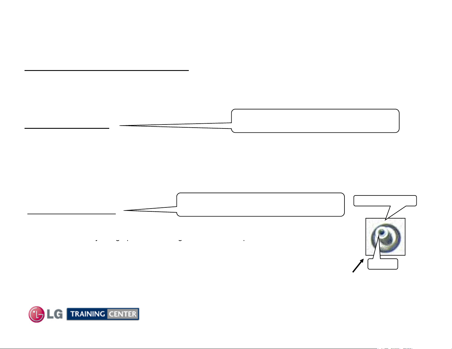
Front IR and Key Pad Removal
FRONT IR/INTELLIGENT SENSOR and POWER BUTTON:
Disconnect P100 and P101. Note: P101 is a ribbon connector. Lift up the locking mechanism and slide the
ribbon cable out. Remove the Board by lifting up on the top tabs, lift the board and remove.
The Key Pad is a thin strip of static sensitive material attached to the front glass. It is not removable.
25
August 2010 42PJ350 Plasma
X Drive Circuit Board Removal ContinuedX Drive Circuit Board Removal Continued
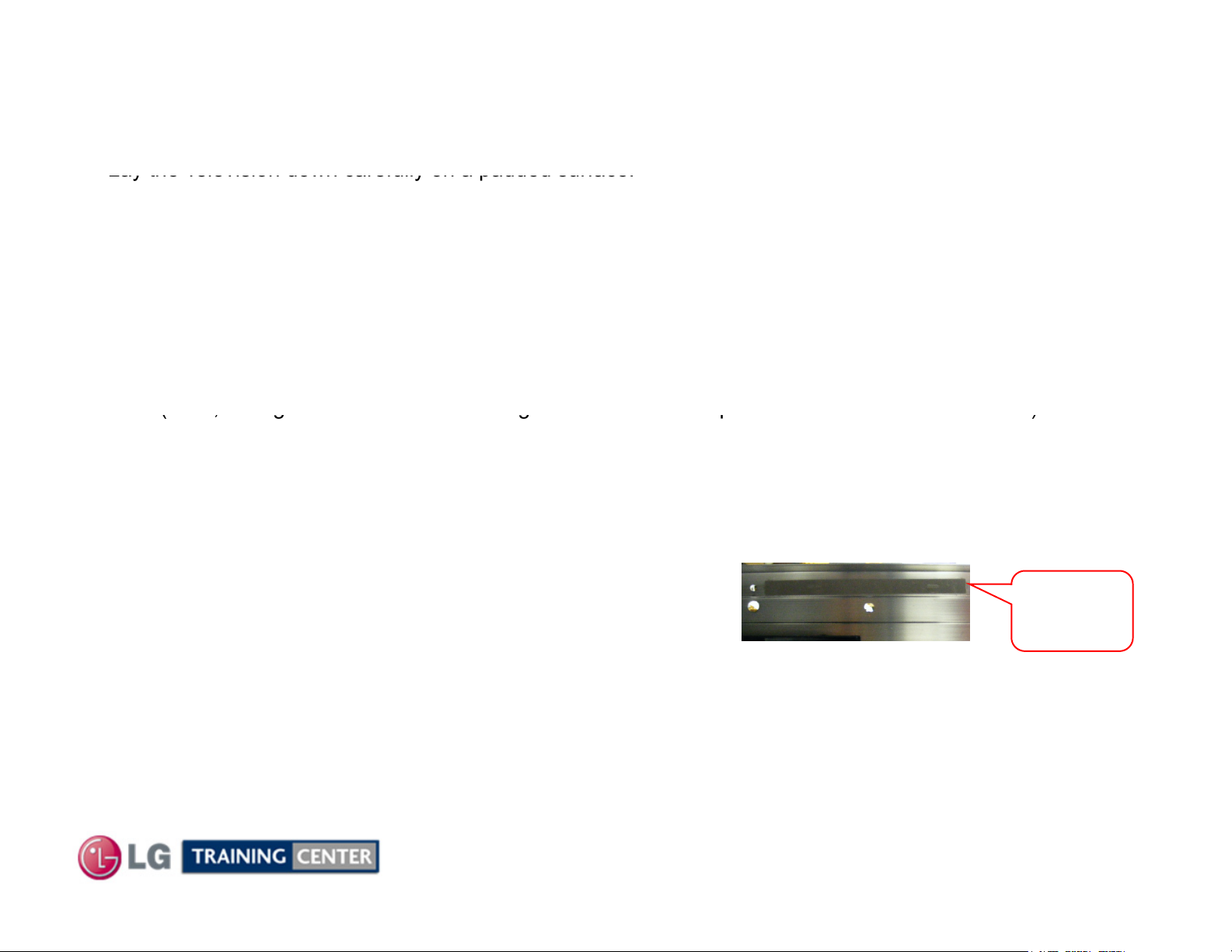
Lay the Television down carefully on a padded surface.
)
Di
P704
P801
(
(, g g p )
Also, note that there several pieces of Chocolate heat transfer material attached all the way across the
X
,
Heat sink
Make sure AC is removed.
Make sure to use at least two people for this process so as not to flex the panel glass.
a) Remove the Back Cover.
b) Remove the Stand (4 Stand Screws were removed during back removal).
c
d) Remove the Stand Metal Support Bracket (5 Screws) 2 Plastic tap thread and 3 Metal thread.
e) Remove the two Vertical support Braces marked “E”.
f) Remove the 7 screws holding the Heat Sink. (Warning: Never run the set with this heat sink removed).
-DRIVE LEFT, AND X-DRIVE RIGHT REMOVAL:
sconnect the two connector on the left side of the Main board,
Note: There are 4 Screws per/brace, 2 Plastic tap thread and 2 Metal thread.
Note, the right brace has a Grounding wire from the AC input which must also be removed).
To remove the heat sink, lift up to release the tacky Chocolate (heat transfer material) and slide the
heat sink to the left to clear the connector wires on the right side.
Note: There are three large pieces of conductive tape on the heat sink that must be removed.
underside of the heat sink. There is a mark on either
side of the tape on the heat sink which shows its locations.
and
.
Chocolate
Heat transfer
material
Disconnect all TCP ribbon cables from the defective X-Drive board and all other Ribbon cables going to
the board.
Remove the (3 Left or Right X) or (5 Center X) screws holding the defective X-Drive board in place.
Remove the board. Reassemble in reverse order. Recheck Va / Vs / VScan / -VY / Z-Drive.
26
August 2010 42PJ350 Plasma
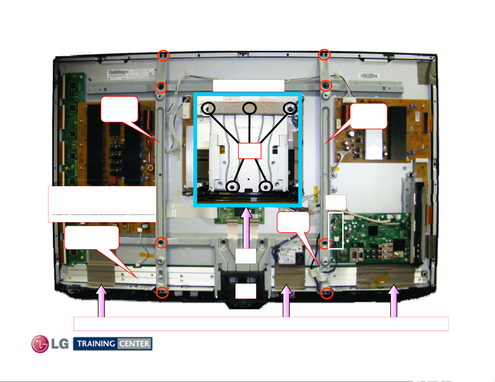
Getting to the X Circuit BoardsGetting to the X Circuit Boards
Right
TCP Heat Sink removed
E
Left
Warning:
Never run the TV with the
With Stand removed
E
D
C
Heat Sink
F
Ground
Wire
D
B
Warning Shorting Hazard: Conductive Tape. Do not allow to touch energized circuits.
27
August 2010 42PJ350 Plasma
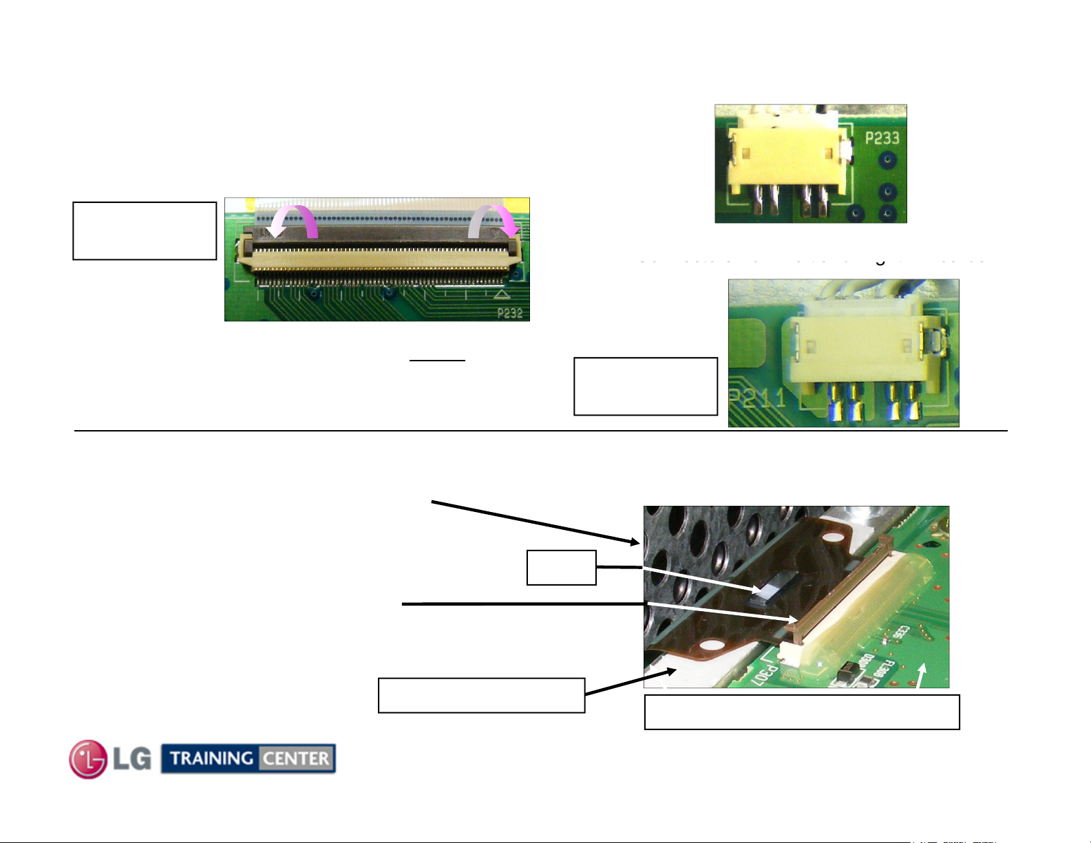
Left and Right X Drive Connector RemovalLeft and Right X Drive Connector Removal
From the X
Boards to the Control Board
Connectors
ds
Connectors from Left and Right X Boards
locki
ibb
P211, P311
It may stick, be careful not to crack TCP
Gently lift the locking mechanism
Disconnect connector P233
See below to Remove the Connections on the X-Boards.
-
There may be tape on these connectors.
P232, P331
Are the same
Remove tape (if present) and Gently pry the
ng mechanism upward and remove the r
cable from the connector.
Removing Connectors to the TCPs.
.
on
Va from the
Y-SUS to
Left X Only
from Left and Right X Boar
P211 to P311
Left X to Right X
Are the same
Carefully lift the TCP ribbon up and off.
.
(See next page for precautions)
upward on all TCP connectors
Left X: P201~206
Right X: P301~306
Cushion (Chocolate)
28
TCP
Example
Flexible ribbon cable connector
August 2010 42PJ350 Plasma
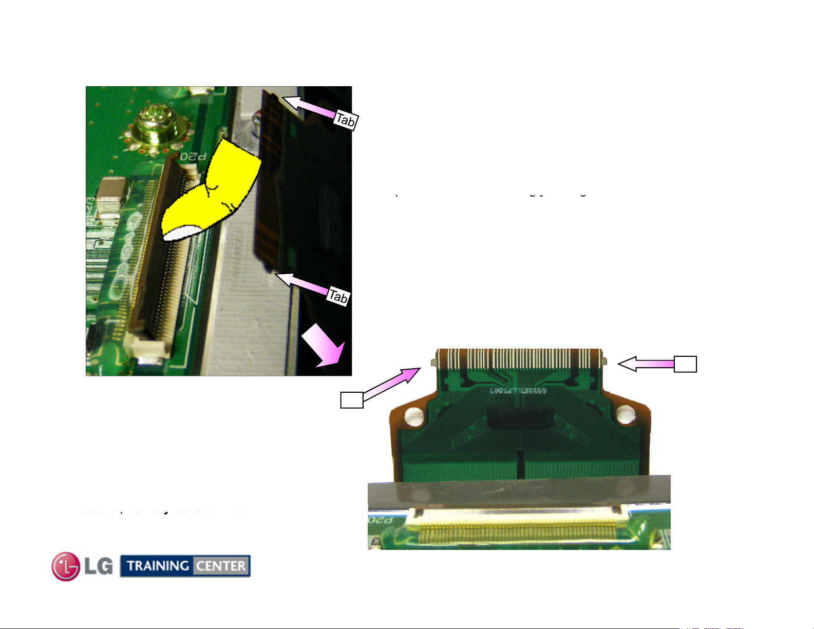
TCP (Tape TCP (Tape CarrierCarrier Package) Generic Removal PrecautionsPackage) Generic Removal Precautions
pgyg
fully into the connector. They have
material, be Very Careful when
Lift up the lock as shown using your fingernail.
(The Lock can be easily broken.
It needs to be handled carefully.)
Separate the TCP from the connector as shown.
TCP Film can be easily damaged.
Handle with care.
The TCP has two small tabs on each
side which lock the ribbon cable
to be lifted up slightly to pull the
connector out.
Note: TCP is usually stuck down
to the Chocolate heat transfer
lifting up on the TCP ribbon cable.
Tab
29
Tab
August 2010 42PJ350 Plasma
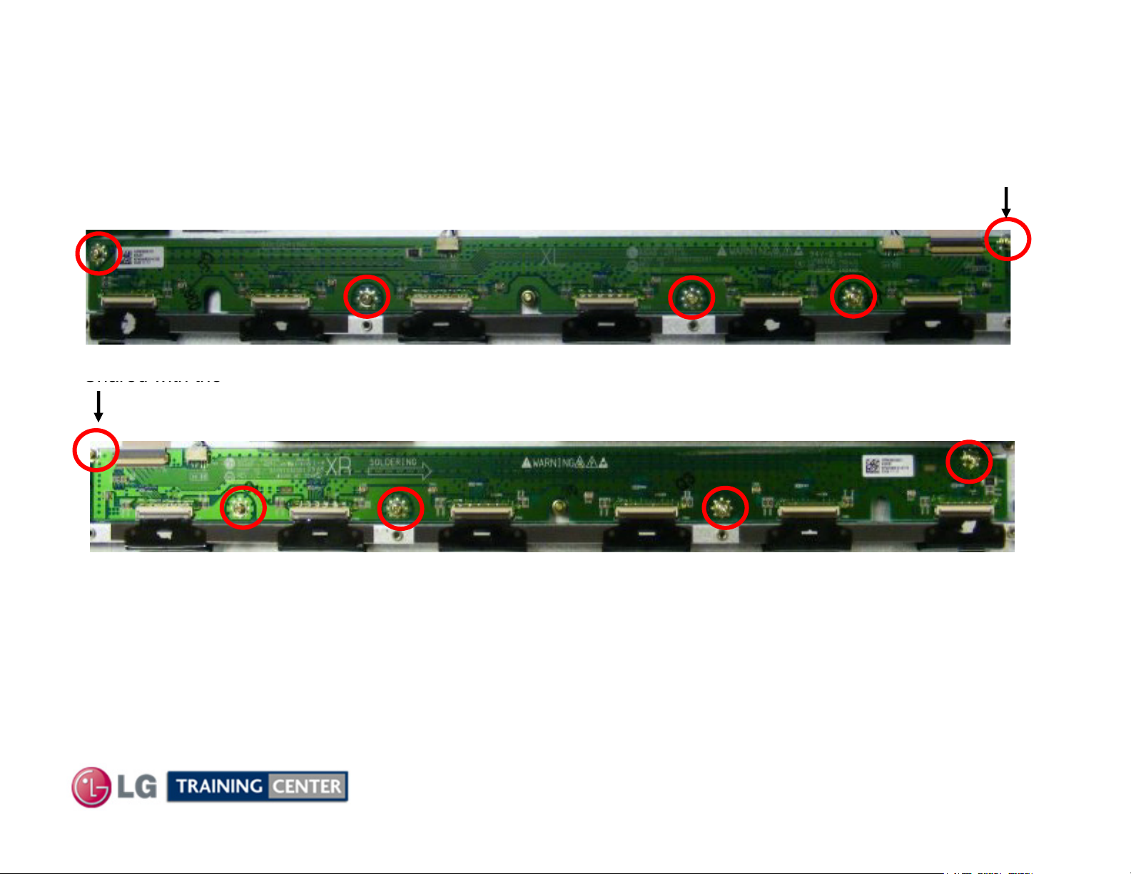
Left and Right X Drive RemovalLeft and Right X Drive Removal
Shared with the
The Right X Board drives the Left 5/16 of the side of the screen vertical electrodes
Remove the 4 screws in Left or Right X-Boards, (9 Total)
Left X
Shared with the
Right X
The Left X Board drives the Right 5/16 of the side of the screen vertical electrodes
The Center X Board drives the Center 3/8 of the of the screen vertical electrodes
30
August 2010 42PJ350 Plasma
 Loading...