

LG 42PG35TR User Manual

Please read this manual carefully before operating
your
TV
Retain it for future reference.
Record model number and serial number of the
TV.
Refer to the label on the back cover and quote this
information
To your dealer when requiring service.
PLASMA TV
OWNER’S MANUAL
PLASMA TV MODELS
4422 PPGG33
**** **
5500 PPGG33
**** **
ENGLISH

ACCESSORIES
1
ACCESSORIES
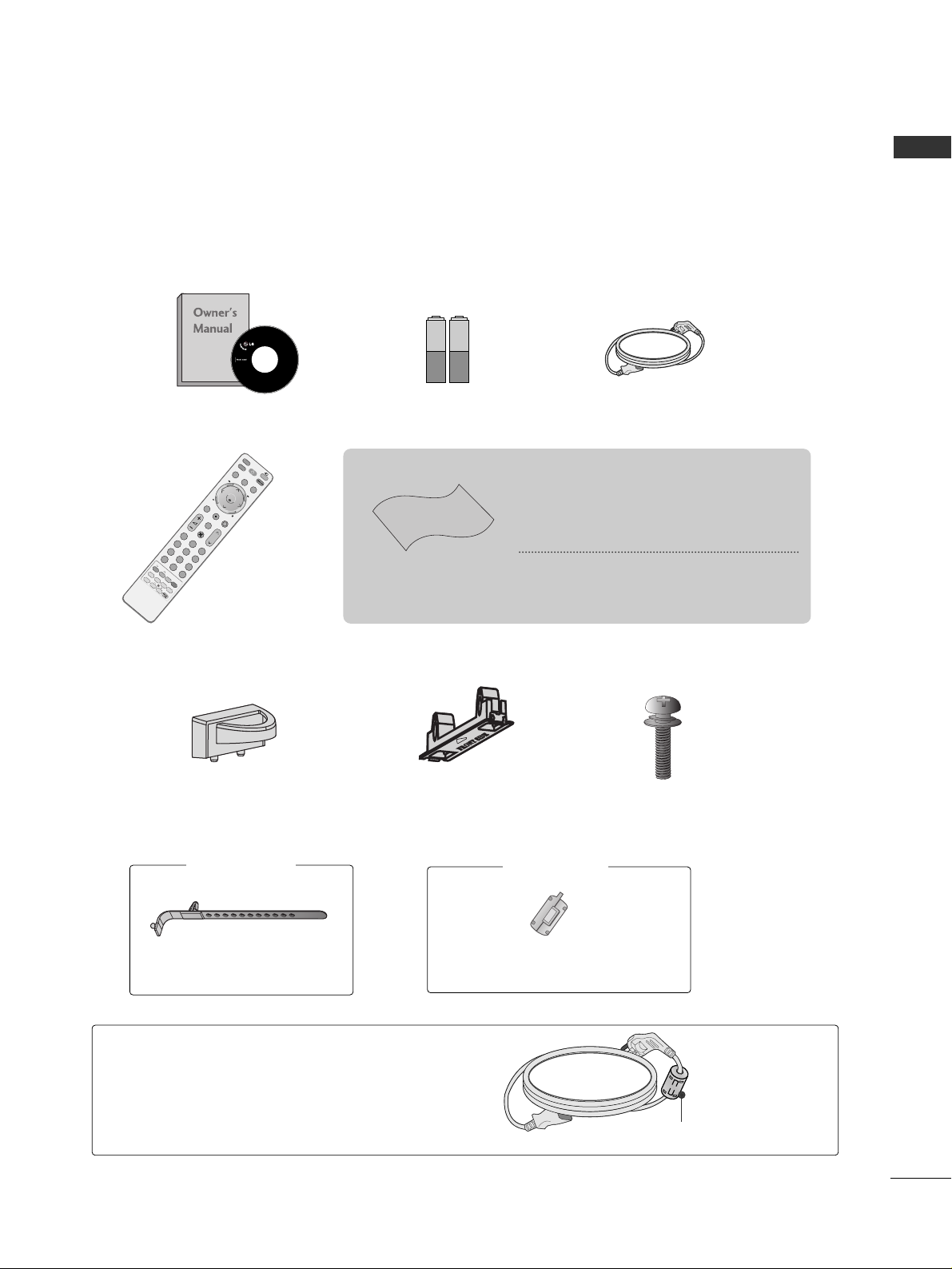
Ensure that the following accessories are included with your TV.
If an accessory is missing, please contact the dealer where you purchased the product.
Owner’s Manual
Remote Control
Power Cord
Polishing Cloth
Polishing cloth for use
on the screen
*Lightly wipe any stains or fingerprints
on the surface of the TV with the polishing cloth.
Do not use excessive force. This may
cause scratching or discolouration.
MUTE
T
IM
E
M
A
C
H
IN
E
A
V
M
O
D
E
F
A
V
TV
IN
P
U
T
STB
P
O
W
ER
M
E
N
U
P
123
456
78
0
9
L
IS
T
Q
.
V
I
E
W
TIME
SIZE
R
E
V
I
N
D
E
X
HOLD
TEXT
PIP
E
X
IT
L
IV
E
T
V
R
E
C
/S
T
O
P
T
I
M
E
S
H
I
F
T
T
I
M
E
S
H
I
F
T
M
A
R
K
SWAP
P
I
P
I
N
P
U
T
P
O
S
I
T
I
O
N
I/II
O
K
PIP PR
This feature is not available for all models.
Batteries
protection cover
(Refer to p.7)
x 4
Bolts for stand assembly
(Refer to p.7)
Cable management clip
(Refer to p.9)
42PG3
***
: 1EA
50PG3
***
: 2EA
Cable Holder
(only 42PG3
***
)
Ferrite core can be used to reduce the electromagnetic
wave when connecting the power cord.
The closer the location of the ferrite core to the power
plug, the better it is.
Use of ferrite core
(
This feature is not available for all models.
)
Install the power plug closely.
This feature is not available for
all models.
Ferrite Core
2
CONTENTS
CONTENTS
Remote Control Key Functions.................................30
Turning on the TV....................................................... 32
Programme Selection ................................................. 32
Volume Adjustment ......................................................32
On Screen Menus Selection and Adjustment.......33
Auto Programme Tuning............................................ 34
Manual Programme Tuning ....................................... 35
Fine Tuning .....................................................................36
Assigning a Station Name..........................................37
Booster............................................................................38
Programme Edit ........................................................... 39
Favourite Programme .................................................. 40
Calling the Programme List....................................... 41
Input Source Selection................................................42
Key lock.......................................................................... 43
AV Mode........................................................................ 44
................................................................. 45
WATCHING TV / PROGRAMME CONTROL
AACCCCEESSSSOORRIIEESS
.....................................................1
PREPARATION
Home Menu......................................................................4
Front Panel Controls..................................................... 5
Back Panel Information ................................................ 6
Stand Installation........................................................... 7
Not Using The Desk-type Stand............................... 7
Please set it up carefully so the product
does not fall over.............................................................8
Back Cover for Wire Arrangement............................ 9
Swivel Stand.................................................................... 9
Desktop Pedestal Installation................................... 10
Wall Mount: Horizontal installation........................ 10
Antenna Connection................................................... 11
EXTERNAL EQUIPMENT SETUP
HD Receiver Setup .......................................................12
DVD Setup..................................................................... 15
VCR Setup ..................................................................... 17
Other A/V Source Setup .......................................... 20
AV Output Setup......................................................... 21
External Stereo Setup................................................. 21
USB in Setup .................................................................22
PC Setup........................................................................23
- Screen Setup for PC Mode................................26
PREPARATION
TIME MACHINE
TimeShift Mode(Pause & Replay of Live TV)...... 48
Format hard disk............................................................51
Instant Recording.........................................................52
Manual Record ..............................................................54
Schedule List..................................................................55
Record Quality...............................................................55
To use the USB device................................................56
Recorded TV Programme List....................................58
USB Backup ..................................................................61
Photo List........................................................................64
Music List........................................................................68
Movie List........................................................................71
Quran...............................................................................73
Subtitle............................................................................77
DivX Registration Code..............................................78
3
CONTENTS
Watching PIP(Picture-in-Picture) .............................79
Picture Size (Aspect Ratio)Control .........................81
Preset Picture Settings
- Picture Mode-Preset............................................83
-
Auto Colour Temperature Control(Warm/Medium/Cool)
..84
Manual Picture Adjustment
- Picture Mode-User option.................................85
- Colour Temperature - User option..................86
-
Picture Improvement Technology
...................87
Demo .................................................................88
Advanced - Cinema......................................................89
Advanced - Black(Darkness) Level...........................90
Picture Reset..................................................................91
Image Sticking Minimization(ISM) Method ..........92
Low-Power Picture Mode............................................93
SOUND & LANGUAGE CONTROL
Auto Volume Leveler....................................................94
Preset Sound Settings - Sound Mode ....................95
Sound Setting Adjustment - User Mode ...............96
Balance ............................................................................97
TV Speakers On/Off Setup .......................................98
I/II
- Stereo/Dual Reception.......................................99
- NICAM Reception..............................................100
- Speaker Sound Output Selection .................100
On-Screen Menu Language Selection
.................... 101
PICTURE CONTROL
APPENDIX
Troubleshooting..........................................................109
Maintenance ................................................................111
Product Specifications...............................................112
Programming the Remote Control ....................... 113
IR Codes ........................................................................115
External Control Through RS-232C ......................117
TIME SETTING
Clock Setup .................................................................102
Auto On/Off Timer Setting .....................................103
Sleep Timer Setting ...................................................104
Auto Shut-off Setting ................................................105
TELETEXT
Switch On/Off ...........................................................106
SIMPLE Text .................................................................106
TOP Text .......................................................................107
FASTEXT .......................................................................107
Special Teletext Functions .......................................108
Home
4
HOME MENU
PREPARATION
PREPARATION
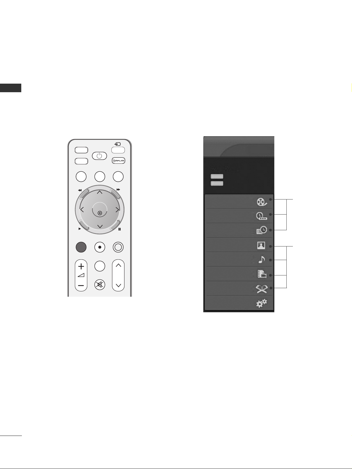
This menu is a contents guide.
In Home Menu, you enter the Recorded list of TIME MACHINE,
Manual Recording of TIME MACHINE, Schedule List ,Photo List,
Music List, Movie List or TV Menu.
MUTE
FAV
TV
INPUT
STB
POWER
P
MENU
EXIT
LIVE TV
TIME MACHINE
AV M O D E
REC/STOP
MARK
T
I
M
E
S
H
I
F
T
T
I
M
E
S
H
I
F
T
O K
G
pp..4488
G
pp..6644~77 66
Recorded TV
Manual Record
Schedule List
Photo List
Music List
Movie List
TV Menu
HIGH
NORMAL
TIME MACHINE
TIME MACHINE
Free Space
40h 11m
68h 33m
Quran
5
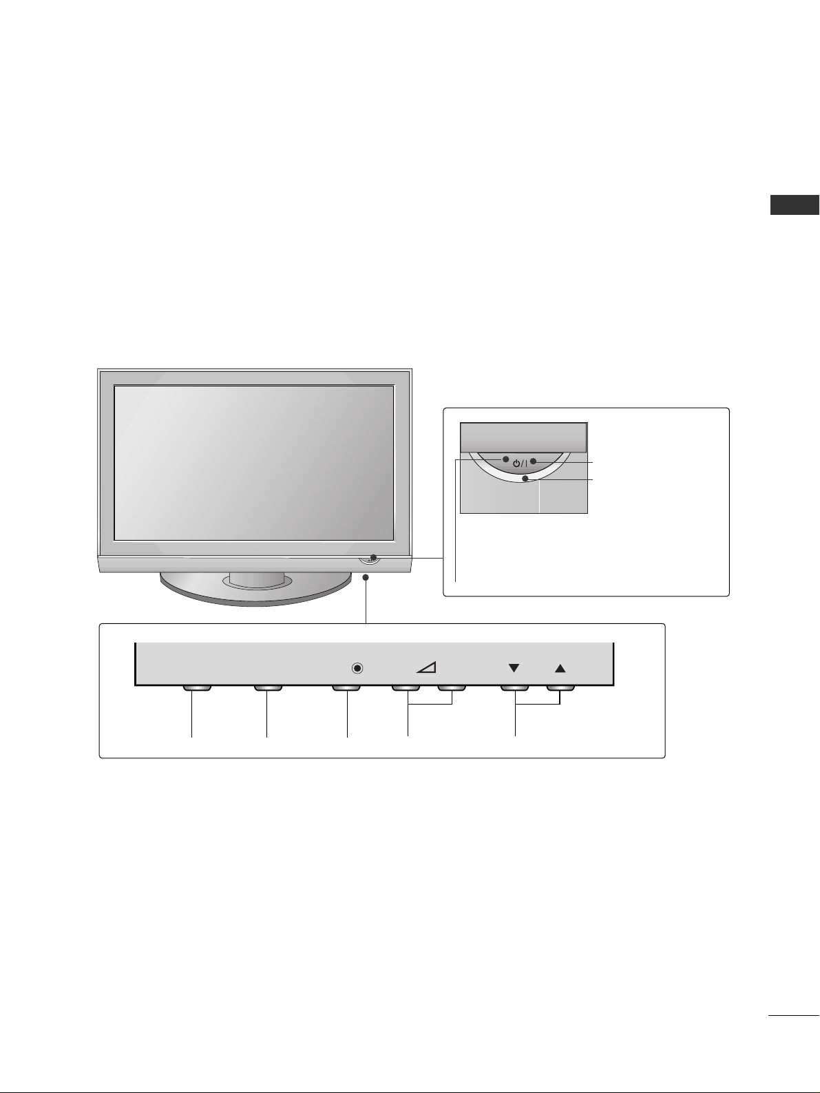
FRONT PANEL CONTROLS
PREPARATION
■
This is a simplified representation of the front panel. Image shown may differ from your TV.
■
If your TV has a protection film attached, remove the film and then wipe the product with a polishing cloth.
PROGRAMMEVOLUMEMENU OKINPUT
Remote Control Sensor
POWER Button
Power/Standby Indicator
• illuminates red in standby mode.
• illuminates green when the TV is
switched on.
OK
MENU
INPUT
INPUT
MENU
OK
- +
P
6
PREPARATION
PREPARATION
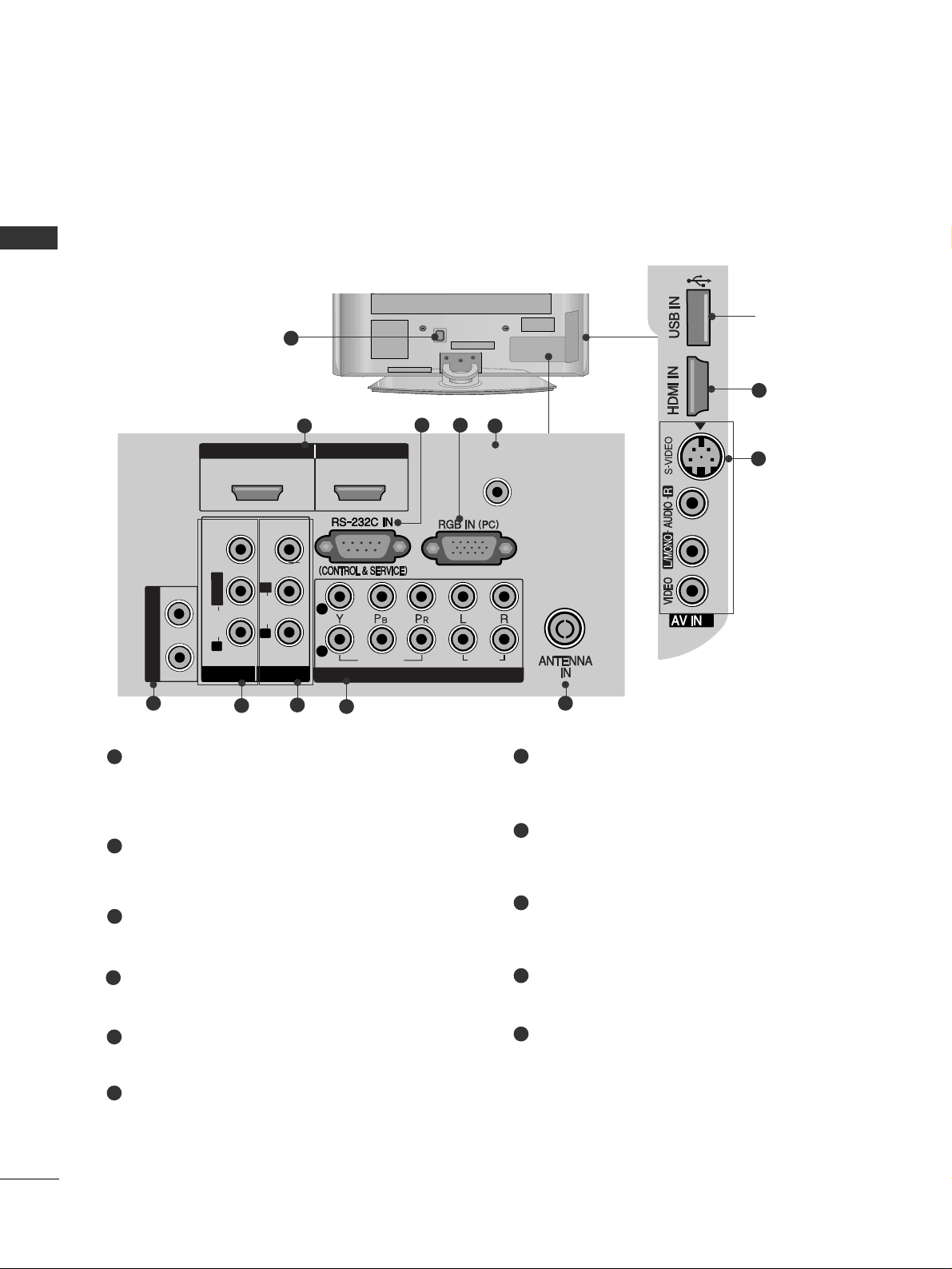
BACK PANEL INFORMATION
A
Image shown may differ from your TV.
Power Cord Socket
This TV operates on an AC power. The voltage is
indicated on the Specifications page. Never
attempt to operate the TV on DC power.
HDMI/DVI IN 1, HDMI IN 2/3
Connect a HDMI signal to HDMI IN. Or DVI (VIDEO)
signal to HDMI/DVI port with DVI to HDMI cable.
RS-232C IN (CONTROL & SERVICE)
Connect to the RS-232C port on a PC.
RGB IN (PC)
Connect the output from a PC.
AUDIO (RGB/DVI)
Connect the audio from a PC or DTV.
VARIABLE AUDIO OUT
Connect an external amplifier or add a subwoofer
to your surround sound system.
AV (Audio/Video) IN 1
Connect audio/video output from an external
device to these jacks.
AV OUT
Connect second TV or monitor to the AV OUT
socket on the TV.
Component Input
Connect a component video/audio device to
these jacks.
Antenna Input
Connect RF antenna to this jack.
AV (Audio/Video) IN 2
Connect audio/video output from an external
device to these jacks.
S-VIDEO
Connect S-Video out from an S-VIDEO device.
1
2
3
4
5
6
7
8
9
10
11
1
L/
MONO
AUDIO
VIDEO
AUDIO
VIDEO
2
5
106
8
9
43
2
11
7
USB Input
HDMI IN HDMI/DVI IN
1 2
AUDIO
(RGB/DVI)
3
VARIABLE AUDIO OUT
AV IN 1
VIDEO
MONO
L/
AUDIO
R
VIDEO
L
AUDIO
R
AV OUT
2
1
VIDEO
COMPONENT IN
AUDIO
2
7
PREPARATION
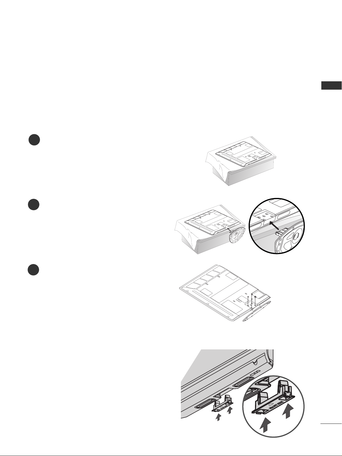
STAND INSTALLATION
A
Image shown may differ from your TV.
only 42PG3
***
Carefully place the TV screen side down on a
cushioned surface to protect the screen from
damage.
Assemble the TV as shown.
Fix the 4 bolts securely using the holes in the
back of the TV.
1
2
3
Not Using the Desk-type Stand
When installing the wall-mounted unit, use the
protection cover for desk-type stand installation.
Insert the PROTECTION COVER into the TV until
clicking sound.
■
Image shown may differ from your TV.
When assembling the desk type stand, check whether the bolt is fully tightened.
(If not tightened fully, the product can tilt forward after the product installation.) If you tighten the bolt with
excessive force, the bolt can deviate from abrasion of the tightening part of the bolt.
8
PREPARATION
PREPARATION
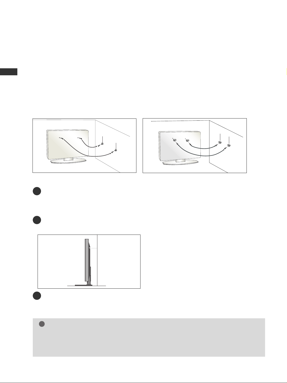
PLEASE SET IT UP CAREFULLY SO THE PRODUCT DOES NOT FALL OVER.
A
You should purchase necessary components to fix the TV to the wall on the market.
A
Position the TV close to the wall to avoid the possibility of it falling when pushed.
A
The instructions shown below are a safer way to
set up the TV, which is to fix it to the wall, avoiding the
possibility of it falling forwards if pulled. This will prevent the TV from falling forward and causing injury.
This will also prevent the TV from damage. Ensure that children do not climb or hang from the TV.
NOTE
!
G
When moving the TV undo the cords first.
G
Use a platform or cabinet string and large enough to support the size and weight of the TV.
G
To use the TV safely make sure that the height of the bracket on the wall and on the TV is the same.
3
1
2
Use the eye-bolts or TV brackets/bolts to fix the product to the wall as shown in the picture.
(If your TV has bolts in the eyebolts, loosen then bolts.)
* Insert the eye-bolts or TV brackets/bolts and tighten them securely in the upper holes.
Secure the wall brackets with bolts to the wall.
Ensure that both brackets are even.
3
Use a strong cord to secure the TV.
Secure the cord in such a way that it becomes taught when the TV is in position.
2
1
2
1
9
PREPARATION
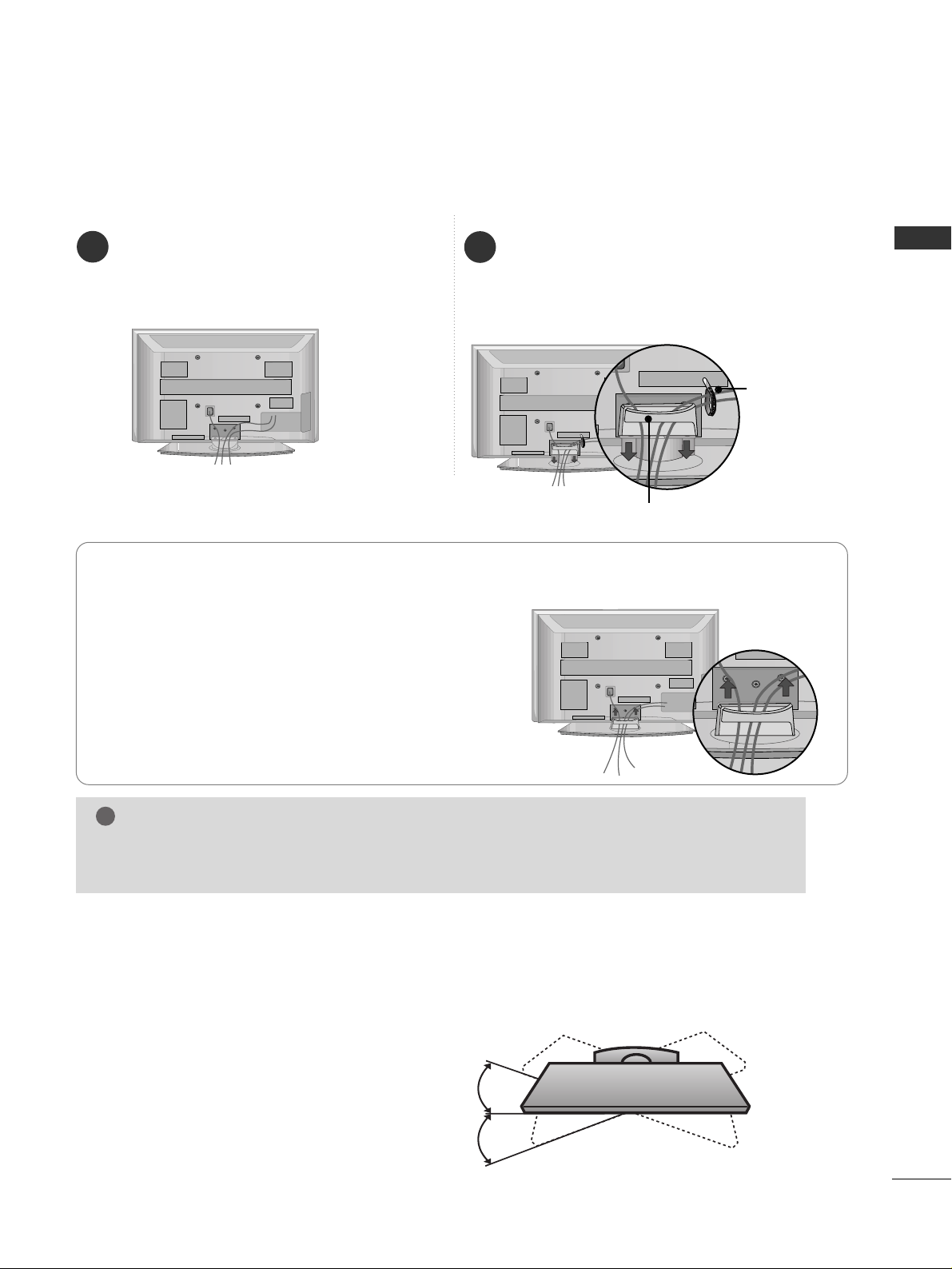
BACK COVER FOR WIRE ARRANGEMENT
SWIVEL STAND
After installing the TV, you can adjust the TV set
manually to the left or right direction by 20
degrees to suit your viewing position.
How to remove the cable management clip
■
Image shown may differ from your TV.
Connect the cables as necessary.
To connect additional equipment, see the
EXTERNAL EQUIPMENT SETUP section.
Install the CABLE MANAGEMENT CLIP as
shown.
If your TV has the CABLE HOLDER, install it
as shown and bundle the cables.
1
2
NOTE
!
GG
Do not use the CABLE MANAGEMENT CLIP to lift the TV.
- If the TV is dropped, you may be injured or the TV may be damaged.
Hold the
CC AABBLLEE MMAA NNAAGGEEMMEENN TT CCLL IIPP
with
both hands and pull it upward.
CABLE MANAGEMENT CLIP
CABLE HOLDER
10
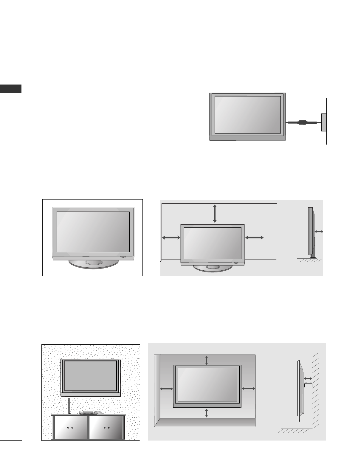
PREPARATION
PREPARATION
A
The TV can be installed in various ways such as on a wall, or on a desktop etc.
A
The TV is designed to be mounted horizontally.
Power Supply
Circuit breaker
EARTHING
Ensure that you connect the earth wire to prevent possible
electric shock. If grounding methods are not possible, have a
qualified electrician install a separate circuit breaker.
Do not try to earth the TV by connecting it to telephone
wires, lightening rods or gas pipes (comma incorrect).
DESKTOP PEDESTAL INSTALLATION
For adequate ventilation allow a clearance of 4” (10cm) all around the TV.
4 inches
4 inches
4 inches
4 inches
WALL MOUNT: HORIZONTAL INSTALLATION
For adequate ventilation allow a clearance of 4” (10cm) all around the TV. We recommend that you use a wall
mounting bracket of LG brand when mounting the TV to a wall.
4 inches
4 inches
4 inches
4 inches
4 inches
11
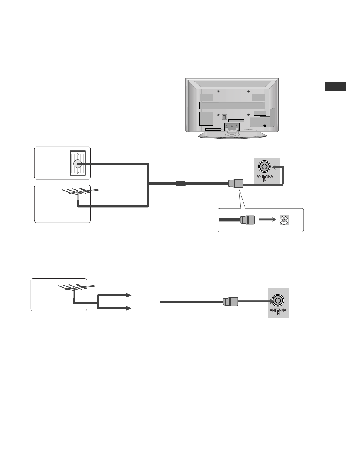
PREPARATION
■
For optimum picture quality, adjust antenna direction.
■
An antenna cable and converter are not supplied.
■
To prevent damage do not connect to the mains outlet until all connections are made between the devices.
Multi-family Dwellings/Apartments
(Connect to wall antenna socket)
Single-family Dwellings /Houses
(Connect to wall jack for outdoor antenna)
Outdoor
Antenna
(VHF, UHF)
Wall
Antenna
Socket
RF Coaxial Wire (75 ohm)
ANTENNA CONNECTION
Antenna
UHF
Signal
Amplifier
VHF
■
In poor signal areas, to achieve better picture quality it may be necessary to install a signal amplifier to the
antenna as shown above.
■
If signal needs to be split for two TVs,use an antenna signal splitter for connection.
12
EXTERNAL EQUIPMENT SETUP
EXTERNAL EQUIPMENT SETUP
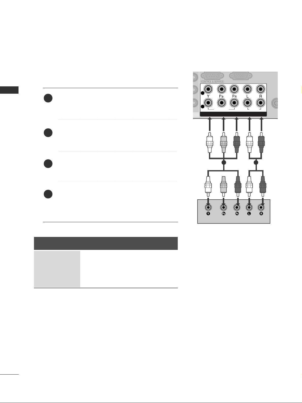
HD RECEIVER SETUP
ANTEN
IN
ANTEN
IN
COMPONENT INCOMPONENT IN
AUDIO
VIDEO
1
2
COMPONENT IN
AUDIO
VIDEO
1
2
12
1 2
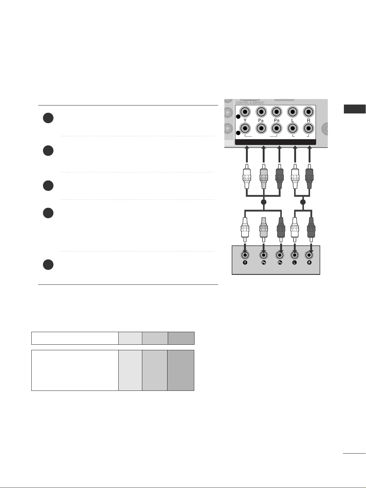
Connecting with a component cable
Connect the video outputs (Y, P
B, PR
)
of the digital set
top box to the
CC OOMMPPOO NNEENNTT IINN VV IIDDEEOO
jacks on the
TV.
Connect the audio output of the digital set-top box to
the
CC OOMMPPOO NNEENNTT IINN AAUUDDII OO
jacks on the TV.
Turn on the digital set-top box.
(
Refer to the owner’s manual for the digital set-top box.
)
Select
Component1 input source using the
IINNPPUUTT
button on the remote control.
If connected to
CC OOMMPPOO NNEENNTT IINN 22
, select
Component2 input source.
2
3
4
1
Signal
480i/576i
480p/576p
720p/1080i
1080p(50/60Hz)
Component 1/2
Yes
Yes
Yes
Yes
HDMI1/DVI, HDMI2,
HDMI3
No
Yes
Yes
Yes
■
To avoid damaging any equipment, never plug in any power cords until you have finished connecting all equipment.
13
EXTERNAL EQUIPMENT SETUP
RG
VARIABLE AUDIO OUT
COMPONCOMPON
VIDEO
1
2
AV IN 1AV IN 1
AV OUTAV OUT
L/ MONO
R
AUDIO
VIDEO
L
R
AUDIO
VIDEO
HDMI IN HDMI/DVI IN
1 2
HDMI-DTV OUTPUT
1
1
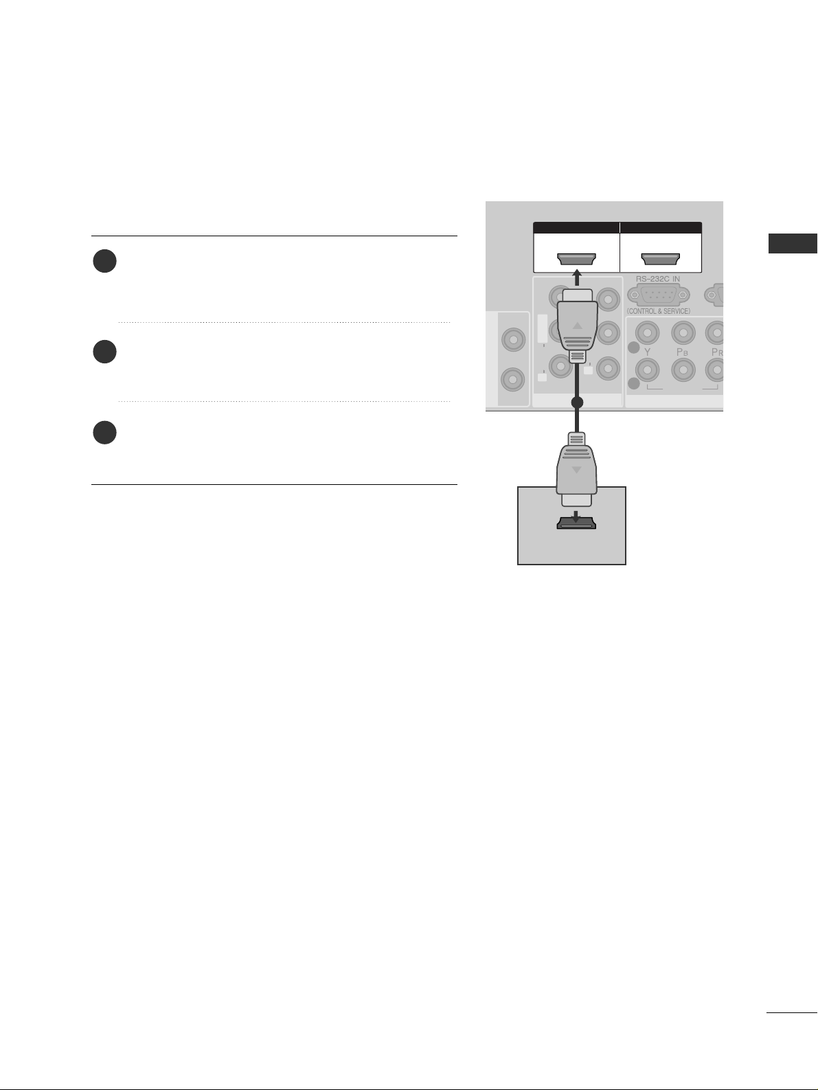
Connecting with a HDMI cable
Connect the HDMI output of the digital set-top box to
the
HHDDMMII //DD VVII IINN 11,HHDDMMII IINN 22
or
HHDDMMII IINN 33
jack on the TV.
Select
HDMI1/DVI, HDMI2 or HDMI3 input source
using the
IINNPPUUTT
button on the remote control.
Turn on the digital set-top box.
(
Refer to the owner’s manual for the digital set-top box.
)
2
3
1

14
EXTERNAL EQUIPMENT SETUP
EXTERNAL EQUIPMENT SETUP
USB IN
L/ MONO
R
AUDIO
S-VIDEO
HDMI IN HDMI IN HDMI/DVI IN HDMI/DVI IN
12
ANTENNA
IN
ANTENNA
IN
RGB IN (PC)
VARIABLE AUDIO OUT
COMPONENT INCOMPONENT IN
AUDIO
VIDEO
1
2
AV IN 1AV IN 1
AV OUTAV OUT
L/MONO
R
AUDIO
VIDEO
L
R
AUDIO
VIDEO
AUDIO
(RGB/DVI)
AUDIO
(RGB/DVI)
HDMI/DVI IN HDMI/DVI IN
1
HDMI/DVI IN
1
1
2
Connect the DVI output of the digital set-top box to the
HHDD MMII//DDVVII IINN 11
jack on the TV.
Connect the audio output of the digital set-top box to the
AAUU DDIIOO((RR GGBB//DDVVII))
jack on the TV.
Turn on the digital set-top box. (Refer to the owner’s manual for the digital set-top box.
)
Select
HDMI1/DVI input source using the
IINNPPUUTT
button on the remote control.
2
3
4
1
Connecting with a HDMI to DVI cable
15
DVD SETUP
EXTERNAL EQUIPMENT SETUP
ANTE
IN
ANTE
IN
COMPONENT INCOMPONENT IN
AUDIO
VIDEO
1
2
COMPONENT IN
AUDIO
VIDEO
1
2
12
1 2
Connecting with a component cable
Component Input ports
To achieve better picture quality, connect a DVD player to the component input ports as shown below.
Component ports on the TV
YPB PR
Video output ports
on DVD player
Y
Y
Y
Y
PB
B-Y
Cb
Pb
P
R
R-Y
Cr
Pr
Connect the video outputs (Y, PB, PR
)
of the DVD to the
CC OOMMPPOO NNEENNTT IINN VV IIDDEEOO
jacks on the TV.
Connect the audio outputs of the DVD to the
CC OOMM PP OO--
NNEENNTT IINN AA UUDD IIOO
jacks on the TV.
Turn on the DVD player, insert a DVD.
Select
Component
11
input source using the
IINNPPUUTT
but-
ton on the remote control.
If connected to
CC OOMMPPOO NNEENNTT IINN 22
, select
Component2
input source.
Refer to the DVD player's manual for operating instructions.
2
3
4
5
1
16
EXTERNAL EQUIPMENT SETUP
EXTERNAL EQUIPMENT SETUP
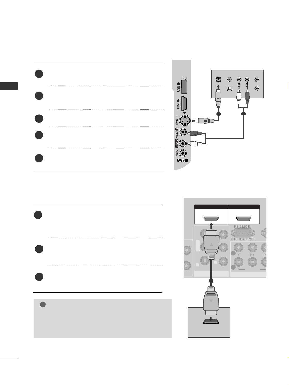
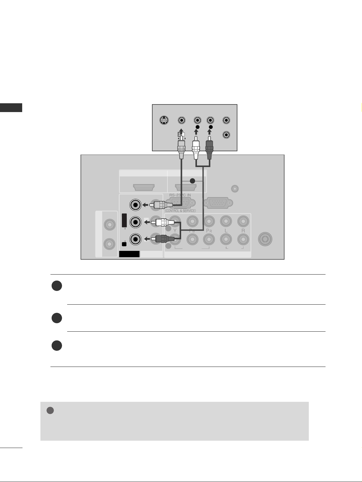
Connecting with an S-Video cable
Connect the S-VIDEO output of the DVD to the
SS--
VVII DDEEOO
input on the TV.
Connect the audio outputs of the DVD to the
AAUU DDII OO
input jacks on the TV.
Turn on the DVD player, insert a DVD.
Select
AV 2 input source using the
IINNPPUUTT
button on
the remote control.
Refer to the DVD player's manual for operating
instructions.
2
3
4
5
1
2
3
L
R
S-VIDEO
VIDEO
OUTPUT
SWITCH
ANT IN
ANT OUT
1
2
RG
COMPONCOMPON
VIDEO
1
2
AV IN 1AV IN 1
AV OUTAV OUT
L/ MONO
R
AUDIO
VIDEO
L
R
AUDIO
VIDEO
HDMI IN HDMI/DVI IN
1 2
HDMI-DVD OUTPUT
1
Connecting the HDMI cable
Connect the HDMI output of the DVD to the
HHDD MMII// DDVVII IINN 11,HHDDMMII IINN 22
or
HHDDMMII IINN 33
jack
on the TV.
Select
HDMI1/DVI, HDMI2 or HDMI3 input source
using the
IINNPPUUTT
button on the remote control.
Refer to the DVD player's manual for operating
instructions.
1
2
3
GG
TV can receive the video and audio signal simultaneously
with using a HDMI cable.
GG
If the DVD player does not support Auto HDMI, you must
set the output resolution appropriately.
NOTE
!
17
VCR SETUP
EXTERNAL EQUIPMENT SETUP
COMPONENT INCOMPONENT IN
AUDIO
VIDEO
1
2
ANTENNA
IN
OUTPUT
SWITCH
ANT IN
R
S-VIDEO VIDEO
ANT OUT
L
Wall Jack
Antenna
1
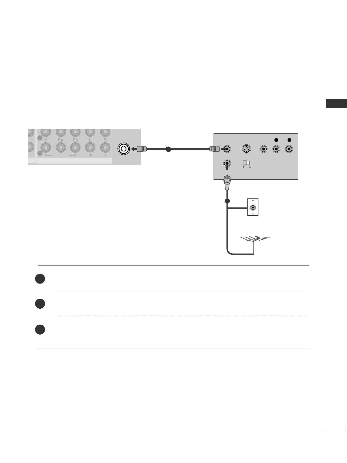
Connecting with a RF Cable
■
To avoid picture noise (interference), allow adequate distance between the VCR and TV.
■
Typically a frozen still picture from a VCR. If 4:3 picture format is used for an extended period the fixed
images on the sides of the screen may remain visible.
Connect the
AANNTT OOUUTT
socket of the VCR to the
AANNTT EENN NNAA IINN
socket on the TV.
Connect the antenna cable to the
AANNTT IINN
socket of the VCR.
Press the
PPLLAA YY
button on the VCR and match the appropriate programme between the TV and VCR for
viewing.
1
2
2
3
1
18
EXTERNAL EQUIPMENT SETUP
EXTERNAL EQUIPMENT SETUP
Connecting with a RCA cable
HDMI IN HDMI IN HDMI/DVI IN HDMI/DVI IN
12
ANTENNA
IN
ANTENNA
IN
AUDIO
(RGB/DVI)
RGB IN (PC)
VARIABLE AUDIO OUT
COMPONENT INCOMPONENT IN
AUDIO
VIDEO
1
2
AV IN 1AV IN 1
AV OUTAV OUT
L
R
AUDIO
VIDEO
L/MONO
R
AUDIOAUDIO
VIDEOVIDEO
L
R
S-VIDEO
VIDEO
OUTPUT
SWITCH
ANT IN
ANT OUT
Connect the
AAUU DDII OO/VVII DDEEOO
jacks between TV and VCR. Match the jack colours (Video = yellow,
Audio Left = white, and Audio Right = red)
Insert a video tape into the VCR and press PLAY on the VCR. (Refer to the VCR owner’s manual.
)
Select
AV 1 input source using the
IINNPPUUTT
button on the remote control.
If connected to
AAVV II NN22
, select
AV 2 input source.
1
2
3
GG
If you have a mono VCR, connect the audio cable from the VCR to the
AAUU DDIIOO LL//MMOO NNOO
jack
of the TV.
NOTE
!
1
EXTERNAL EQUIPMENT SETUP
19
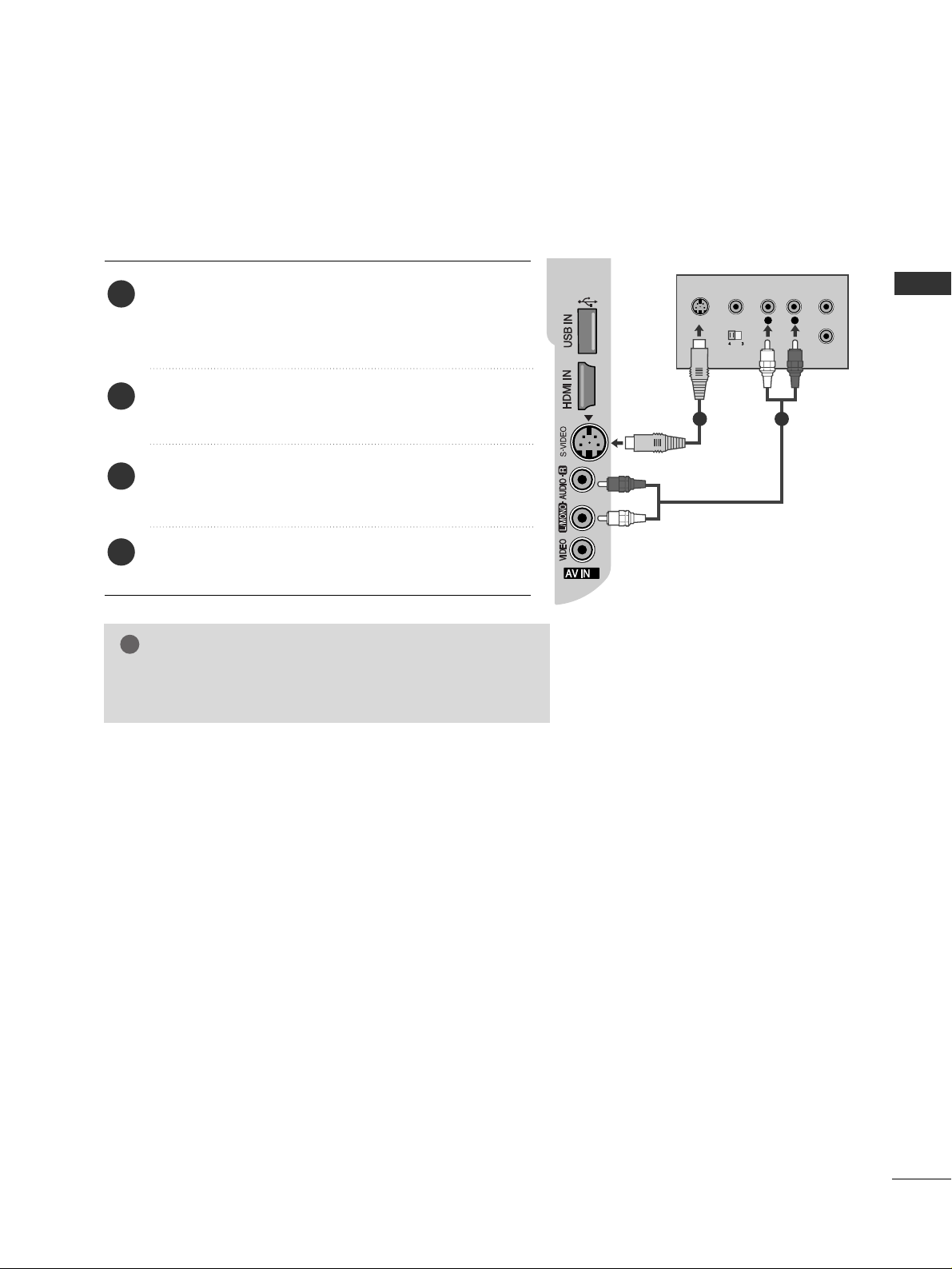
GG
If both S-VIDEO and VIDEO sockets have been connected to
the S-VHS VCR simultaneously, only the S-VIDEO can be
received.
NOTE
!
2
3
L
R
S-VIDEO
VIDEO
OUTPUT
SWITCH
ANT IN
ANT OUT
Connecting with a S-Video cable
Connect the S-VIDEO output of the VCR to the S
--
VVII DDEE OO
input on the TV. The picture quality is
improved; compared to normal composite (RCA cable)
input.
Connect the audio outputs of the VCR to the AUDIO
input jacks on the TV.
Insert a video tape into the VCR and press PLAY on
the VCR. (Refer to the VCR owner’s manual.)
Select
AV 2 input source using the
IINNPPUUTT
button on
the remote control.
2
3
4
1
1 2
20
OTHER A/V SOURCE SETUP
EXTERNAL EQUIPMENT SETUP
EXTERNAL EQUIPMENT SETUP
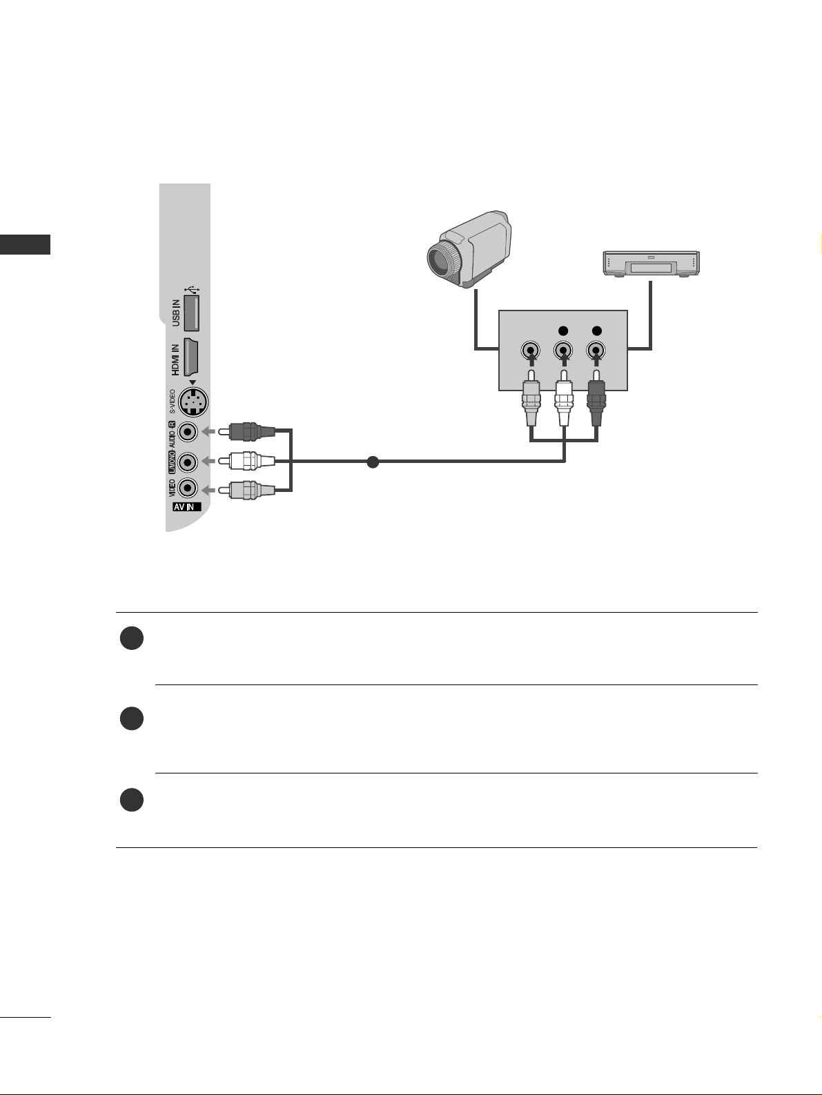
2
3
L R
VIDEO
Camcorder
Video Game Set
1
Connect the
AAUU DDII OO/VVII DDEEOO
jacks between TV and external equipment. Match the jack colours
.
(
Video = yellow, Audio Left = white, and Audio Right = red
)
Select AV 2 input source with using the
IINNPPUUTT
button on the remote control.
If connected to
AAVV II NN11
, select
AV 1 input source.
Operate the corresponding external equipment.
Refer to external equipment operating guide.
1
2
3
EXTERNAL EQUIPMENT SETUP
21
AV OUTPUT SETUP
EXTERNAL STEREO SETUP
COCO
VIDE
1
2
AV IN 1AV IN 1
AV OUTAV OUT
L/ MONO
R
AUDIO
VIDE
L
R
AUDIO
VIDE
VARIABLE AUDIO OUT
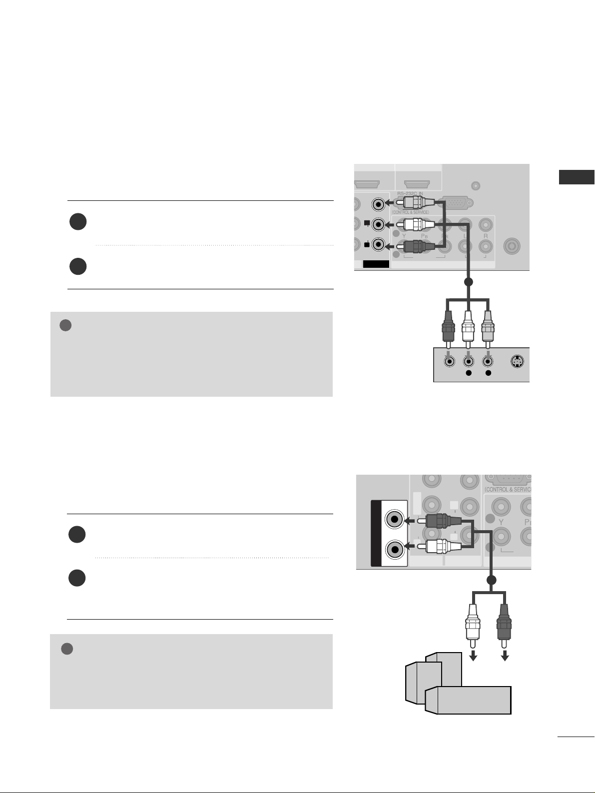
GG
When connecting with external audio equipments, such as
amplifiers or speakers, please turn the TV speakers off.
(
GG
pp..9988
)
NOTE
!
Use to connected either an external amplifier, or add a subwoofer to your surround sound system.
Connect the input jack of the stereo amplifier to the
VVAARRII AABBLLEE AAUU DDIIOO OOUU TT
jacks on the TV.
Set up your speakers through your analog stereo
amplifier, according to the instructions provided with
the amplifier.
2
1
11
The TV has a special signal output capability which allows you to hook up the second TV or monitor.
HDMI IN HDMI IN HDMI/DVI IN HDMI/DVI IN
12
ANTENNA
IN
ANTENNA
IN
AUDIO
(RGB/DVI)
RGB IN (PC)
COMPONENT INCOMPONENT IN
AUDIO
VIDEO
1
2
AV OUTAV OUT
L
R
AUDIOAUDIO
VIDEOVIDEO
L R
S-VIDEOVIDEO
Connect the second TV or monitor to the TV’s
AAVV OOUUTT
jacks.
See the Operating Manual of the second TV or monitor
for further details regarding that device’s input settings.
GG
Component, RGB, HDMI input sources cannot be used for
AV out.
GG
We recommend to use the AV OUT jacks for VCR recording.
NOTE
!
2
1
1
22
USB IN SETUP
EXTERNAL EQUIPMENT SETUP
EXTERNAL EQUIPMENT SETUP
2
3
or
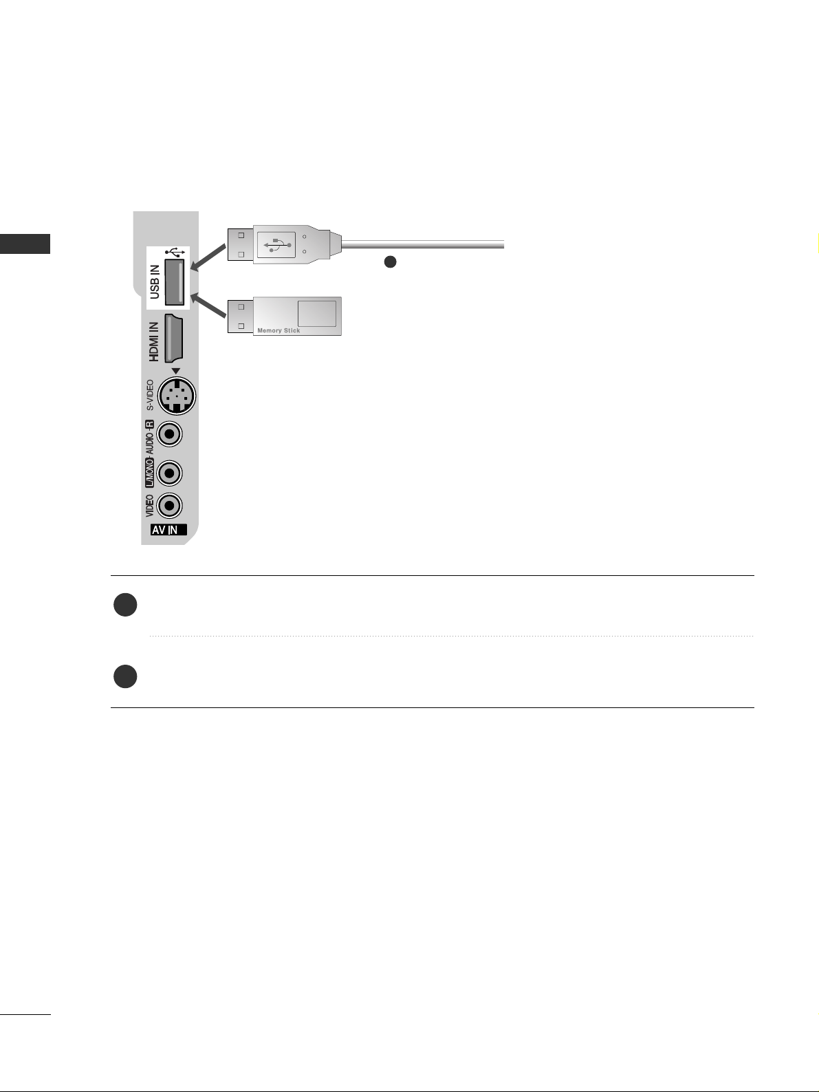
Connect the USB device to the
UUSSBB II NN
jacks on the side of TV.
After connecting the
UUSSBB II NN
jacks, you use the
TTIIMMEE MMAACCHHII NNEE
function. (
GG
pp..5566
)
2
1
1
23
PC SETUP
EXTERNAL EQUIPMENT SETUP
12
ANTENNA
IN
ANTENNA
IN
VARIABLE AUDIO OUT
COMPONENT INCOMPONENT IN
AUDIO
VIDEO
1
2
AV IN 1AV IN 1
AV OUTAV OUT
L/M
O
NO
R
A
U
D
IO
V
ID
E
O
L
R
A
U
D
IO
V
ID
E
O
RGB OUTPUT
AUDIO
AUDIO
(RGB/DVI)
RGB IN (PC)
1
2
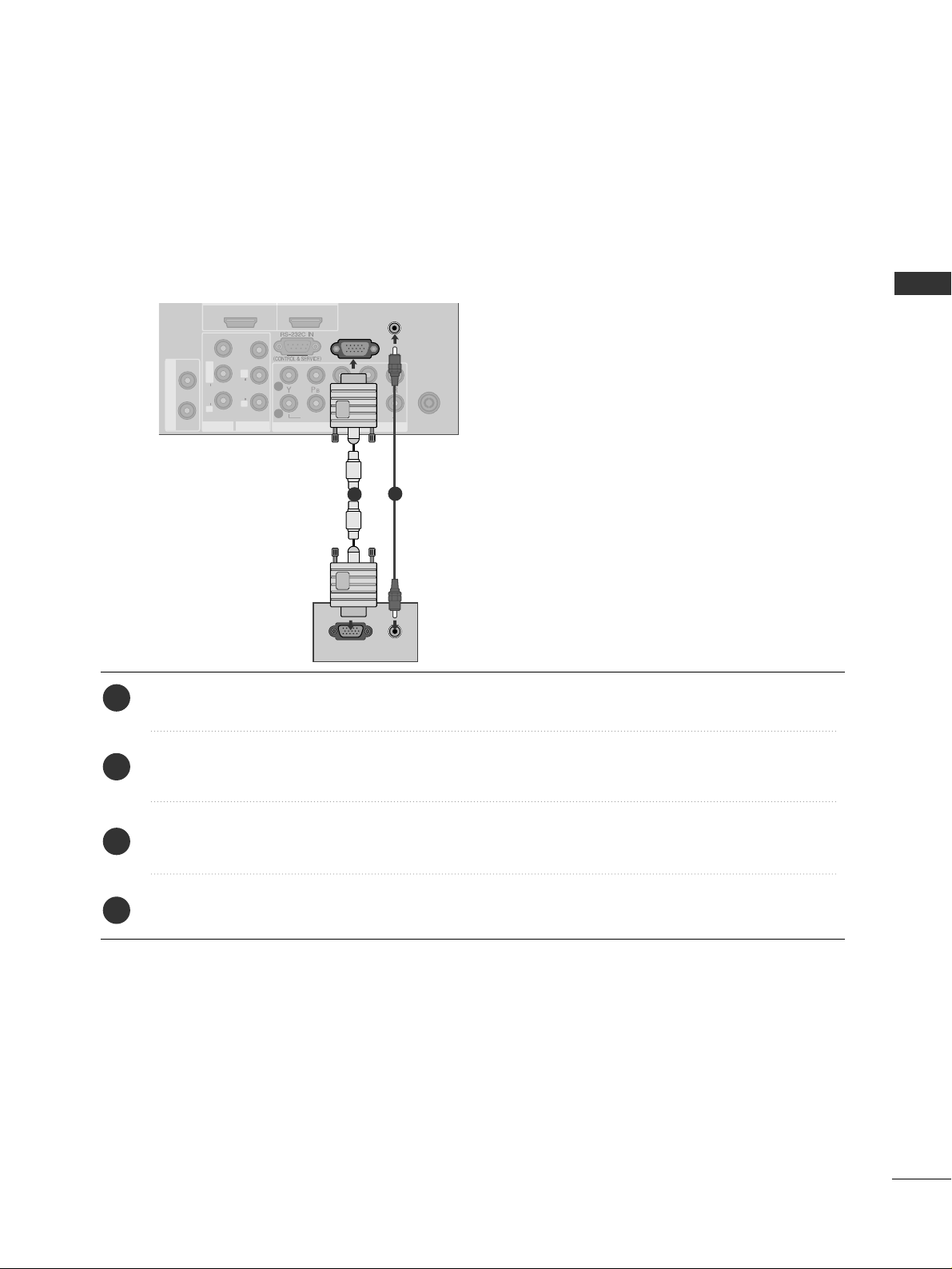
This TV provides Plug and Play capability, meaning that the PC adjusts automatically to the TV's settings.
Connecting with a D-sub 15 pin cable
Connect the RGB output of the PC to the
RRGG BB IINN ((PPCC))
jack on the TV.
Connect the PC audio output to the
AAUU DDIIOO((RR GGBB//DDVVII))
jack on the TV.
Turn on the PC and the TV.
Select
RGB input source using the
IINNPPUUTT
button on the remote control.
2
3
4
1
EXTERNAL EQUIPMENT SETUP
24
EXTERNAL EQUIPMENT SETUP
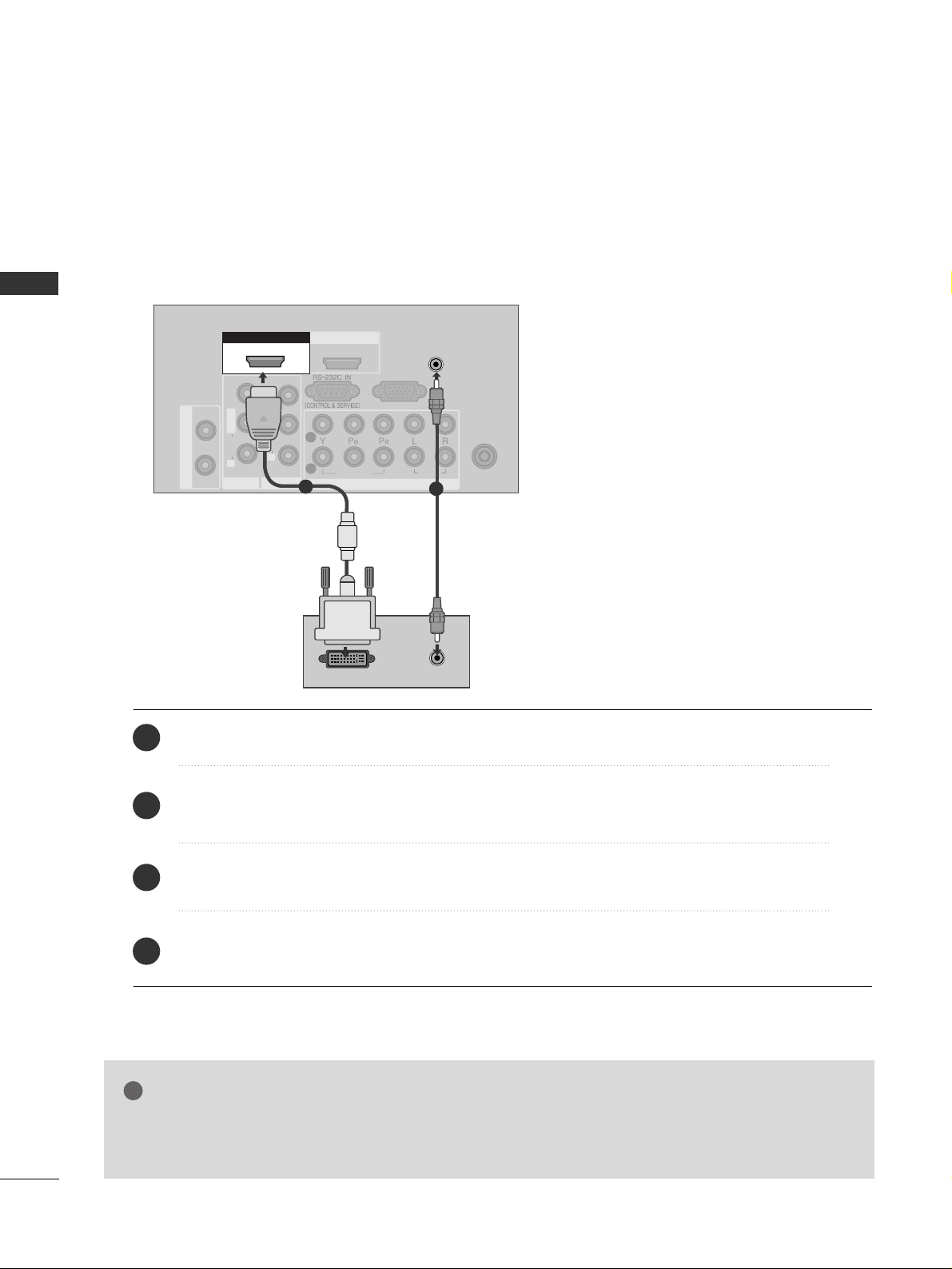
Connecting with a HDMI to DVI cable
HDMI IN HDMI IN HDMI/DVI IN HDMI/DVI IN
12
ANTENNA
IN
ANTENNA
IN
RGB IN (PC)
VARIABLE AUDIO OUT
COMPONENT INCOMPONENT IN
AUDIO
VIDEO
1
2
AV IN 1AV IN 1
AV OUTAV OUT
L/MONO
R
AUDIO
VIDEO
L
R
AUDIO
VIDEO
AUDIO
(RGB/DVI)
AUDIO
(RGB/DVI)
HDMI/DVI IN HDMI/DVI IN
1
HDMI/DVI IN
1
DVI-PC OUTPUT
AUDIO
1
2
Connect the DVI output of the PC to the
HHDD MMII//DDVVII IINN 11
jack on the TV.
Connect the PC audio output to the
AAUU DDIIOO (( RRGG BB//DDVVII ))
jack on the TV.
Turn on the PC and the TV.
Select
HDMI1/DVI input source using the
IINNPPUUTT
button on the remote control.
2
3
4
1
GG
If the PC has a DVI output and no HDMI output, a separated audio connection is necessary.
GG
If the PC does not support Auto DVI, you need to set the output resolution appropriately.
NOTE
!
EXTERNAL EQUIPMENT SETUP
25
NOTE
!
G
To enjoy vivid picture and sound, connect a PC to
the set.
G
Avoid keeping a fixed image on the set’s screen for
prolonged periods of time. The fixed image may
become permanently imprinted on the screen; use
a screen saver when possible.
G
Connect the PC to the RGB (PC) of the set; change
the resolution.
G
There might be noise according to some resolution,
vertical pattern, contrast or brightness in PC mode.
Change the PC mode to another resolution or
change the refresh rate to another rate or adjust the
brightness and contrast on the menu until the picture is clear. If the refresh rate of the PC graphic
card can not be changed, change the PC graphic
card or consult the manufacturer of the PC graphic
card.
G
The synchronization input waveform for Horizontal
and Vertical frequencies are separate.
G
We recommend using 1024x768, 60Hz (42PG3
***
) /
1360x768, 60Hz (50PG3
***
) for the PC mode, these
should provide the best picture quality.
G
Connect the signal cable from the monitor output
port of the PC to the RGB (PC/DTV) port of the
set or the signal cable from the HDMI output port
of the PC to the HDMI IN (or HDMI/DVI IN) port
on the set.
G
Connect the audio cable from the PC to the Audio
input on the set. (Audio cables are not included
with the set).
G
If using a sound card, adjust PC sound as required.
G
This set uses a VESA Plug and Play Solution. The
set provides EDID data to the PC system with a
DDC protocol. The PC adjusts automatically when
using this set.
G
DDC protocol is preset for RGB (Analog RGB),
HDMI (Digital RGB) mode.
G
If required, adjust the settings for Plug and Play
functionality
G
If the graphic card on the PC does not output analogue and digital RGB simultaneously, connect only
one of either RGB or HDMI IN (or HDMI/DVI IN) to
display the PC output on the set.
G
If the graphic card on the PC does output analogue
and digital RGB simultaneously, switch the TV set to
either RGB or HDMI; (the other mode is set to Plug
and Play automatically by the set.)
G
DOS mode may not work depending on the video
card if you use a HDMI to DVI cable.
G
If you use too long an RGB-PC cable, there may be
interference on the screen. We recommend using
under 5m of cable. This provides the best picture
quality
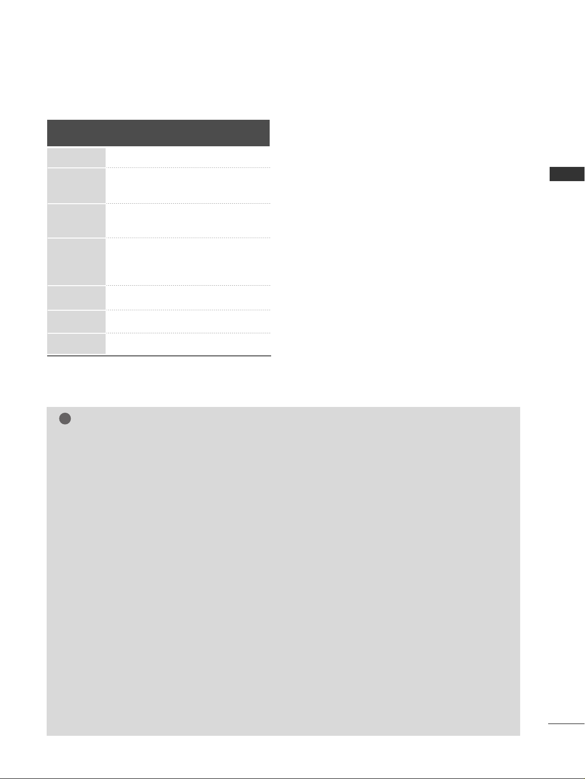
Supported Display Resolution (RGB PC mode)
Resolution
720x400
640x480
800x600
1024x768
1280x768
1360x768
1366x768
31.468 70.08
31.469 59.94
37.500 75.00
37.879 60.31
46 .875 75. 00
48.363 60.00
56.476 70.06
60.023 75.02
47.776 59.87
47.712 60.01
47.70 60.00
Horizontal
Frequency(kHz)
Vertical
Frequency(Hz)
EXTERNAL EQUIPMENT SETUP
26
EXTERNAL EQUIPMENT SETUP
Screen Setup for PC mode
Picture Mode
Colour Temperature
Advanced
Aspect Ratio
Picture Reset
Screen
Demo
SETUP
O
AUDIO
O
TIME
O
OPTION
O
PICTURE G
Prev.
MENU
TIME MACHINE
O
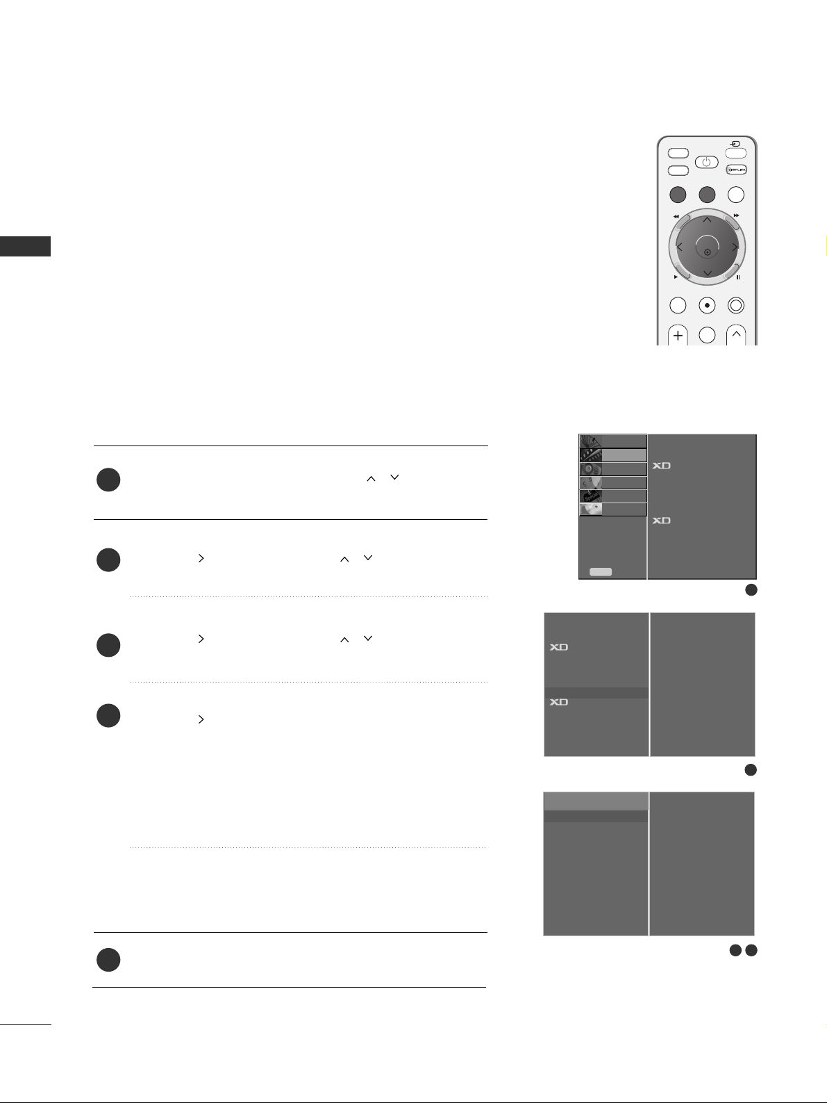
Press the
MMEENN UU
button and then use
//
button to
select the
PICTURE menu.
Press the button and then use
//
button to select
Screen.
Press the button and then use
//
button to select
Auto Config..
Press the button to start
Auto Config..
• When
AAuuttoo ccoonnffii gg..
has finished, OK will be shown on
screen.
• If the position of the image is still not correct, try Auto
adjustment again.
• If picture needs to be adjusted again after Auto adjust-
ment in RGB (PC), you can adjust the
Manual Config..
Press the
EEXXIITT
button to return to TV viewing.
Automatically adjusts picture position and minimizes image
instability. After adjustment, if the image is still not correct,
your TV is functioning properly but needs further adjustment.
AAuutt oo cc oonnffiigguurr ee
This function is for automatic adjustment of the screen posi-
tion, clock, and phase. The displayed image will be unstable for
a few seconds while the auto configuration is in progress..
1
2
3
4
5
Auto Configure (RGB mode only)
1
3 4
2
To Set
Auto Config. G
Manual Config.
XGA Mode
Reset
To Set
Picture Mode
Colour Temperature
Advanced
Aspect Ratio
Picture Reset
Screen
G
Demo
FAV
TV
INPUT
STB
POWER
MENU
EXIT
LIVE TV
TIME MACHINE
AV MODE
REC/STOP
MARK
T
I
M
E
S
H
I
F
T
T
I
M
E
S
H
I
F
T
O K
Screen
27
EXTERNAL EQUIPMENT SETUP
Picture Mode
Colour Temperature
Advanced
Aspect Ratio
Picture Reset
Screen
Demo
SETUP
O
AUDIO
O
TIME
O
OPTION
O
PICTURE G
Prev.
MENU
TIME MACHINE
O
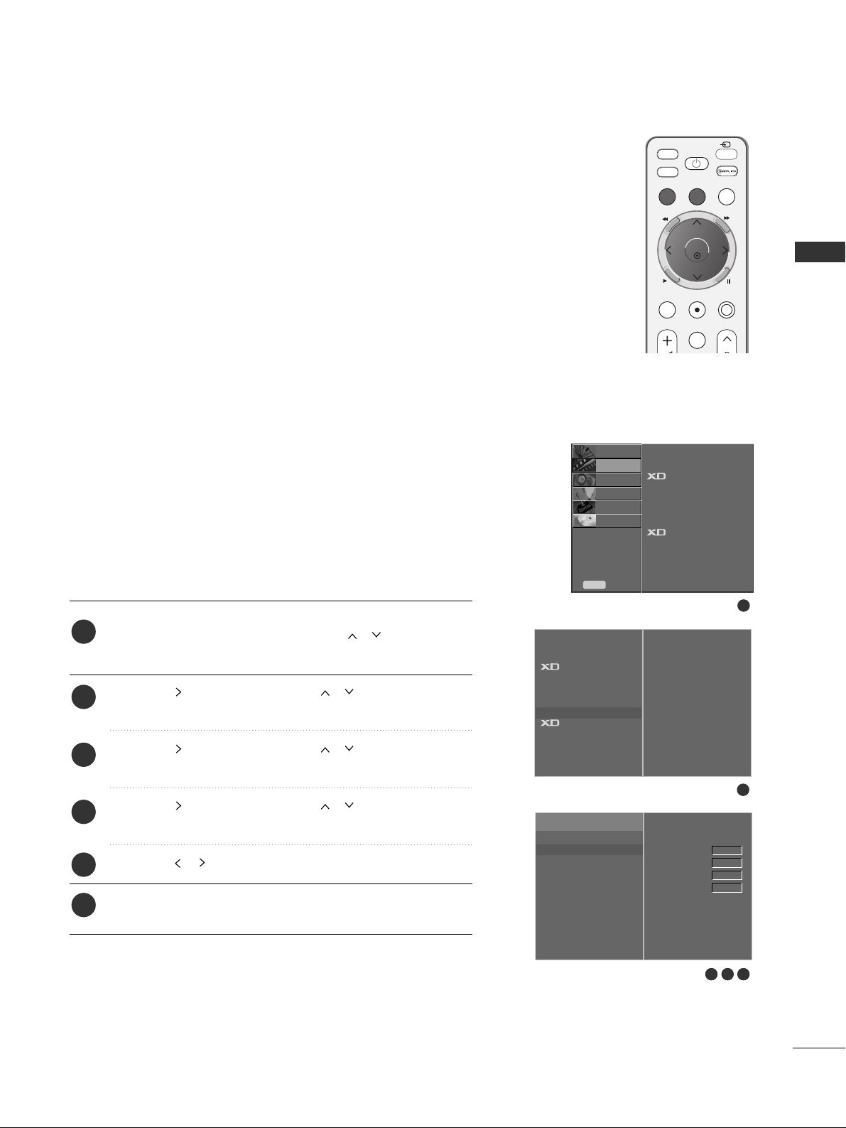
If the picture isn’t clear after auto adjustment and especially if
characters are still trembling, adjust the picture phase manually.
To correct the screen size, adjust
CC lloocckk
.
This function works in the following mode : RGB, COMPONENT
(480p/576p/720p/1080i/1080p), HDMI
(480p/576p/720p/1080i/1080p).
It’s not available to use Phase, Clock function in COMPONENT
(480p/576p/720p/1080i/1080p), HDMI
(480p/576p/720p/1080i/1080p).
CC lloocckk
Clock This function is to minimize any vertical bars or
stripes visible on the screen background the horizontal
screen size will also change.
PPhhaass ee
This function allows you to remove any horizontal noise
and clear or sharpen the image of characters.
Press the
MMEENN UU
button and then use
//
button to
select the
PICTURE menu.
Press the button and then use
//
button to select
Screen.
Press the button and then use
//
button to select
Manual Config..
Press the button and then use
//
button to select
Phase, Clock, H-Position or V-Position.
Press the
//
button to make appropriate adjustments.
Press the
EEXXIITT
button to return to TV viewing.
1
2
3
4
5
6
Adjustment for screen Phase, Clock, Position
1
3 4 5
2
To Set
Auto Config.
Manual Config.
G
XGA Mode
Reset
Phase
Clock
H-Position
V-Position
0
0
0
0
Picture Mode
Colour Temperature
Advanced
Aspect Ratio
Picture Reset
Screen
G
Demo
Screen
FAV
TV
INPUT
STB
POWER
MENU
EXIT
LIVE TV
TIME MACHINE
AV MODE
REC/STOP
MARK
T
I
M
E
S
H
I
F
T
T
I
M
E
S
H
I
F
T
O K
28
EXTERNAL EQUIPMENT SETUP
EXTERNAL EQUIPMENT SETUP
Picture Mode
Colour Temperature
Advanced
Aspect Ratio
Picture Reset
Screen
Demo
SETUP
O
AUDIO
O
TIME
O
OPTION
O
PICTURE G
Prev.
MENU
TIME MACHINE
O
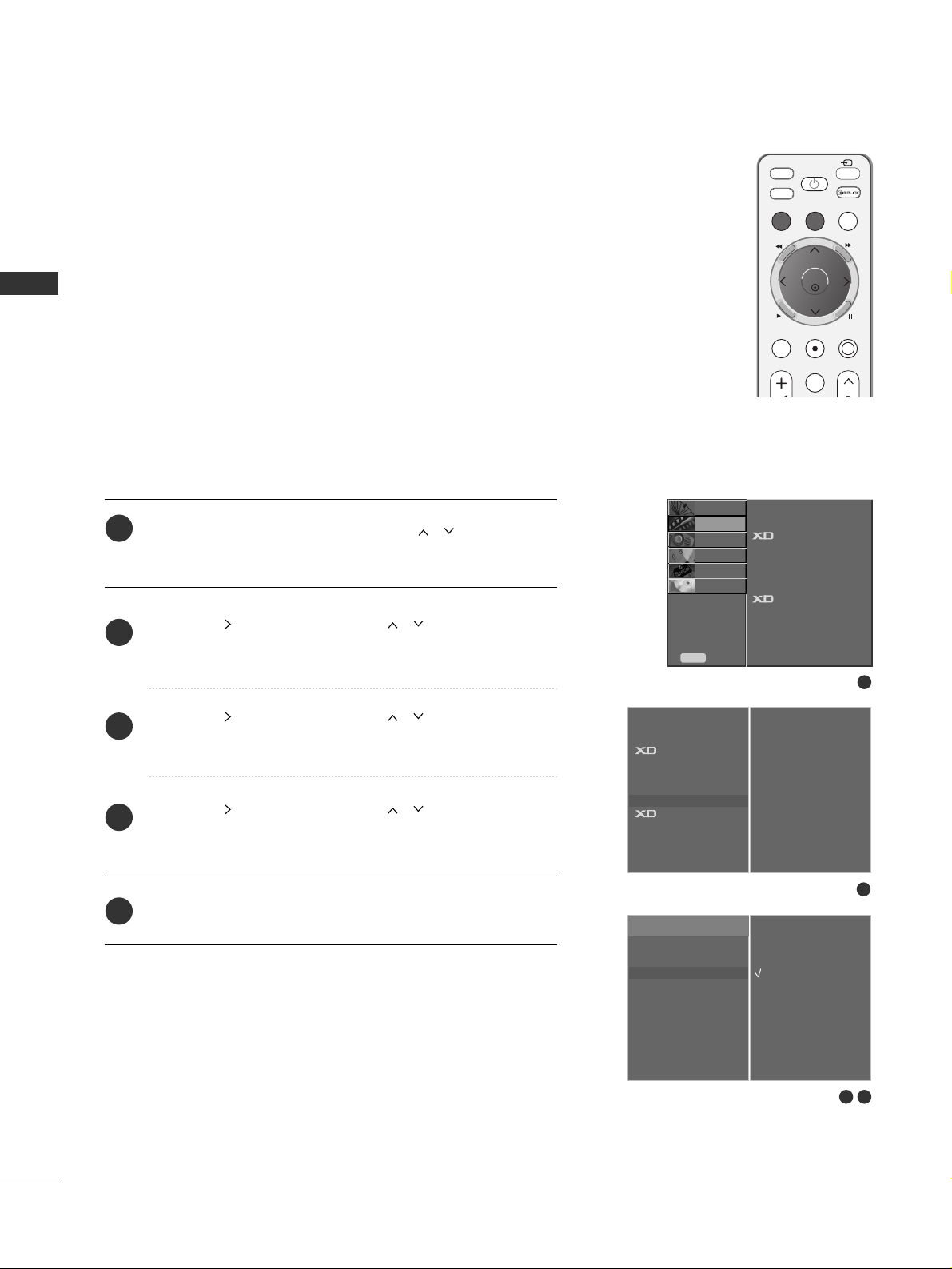
To view a normal picture, match the resolution of RGB mode
and selection of XGA mode.
This function works in the following mode: RGB mode.
Press the
MMEENN UU
button and then use
//
button to
select the
PICTURE menu.
Press the button and then use
//
button to select
Screen.
Press the button and then use
//
button to select
XGA Mode .
Press the button and then use
//
button to select
the desired XGA resolution.
Press the
EEXXIITT
button to return to TV viewing.
Selecting Wide XGA mode
1
2
3
4
5
1
3 4
2
To Set
Auto Config.
Manual Config.
XGA Mode
G
Reset
1024 X 768
1280 X 768
1360 X 768
1366 X 768
Picture Mode
Colour Temperature
Advanced
Aspect Ratio
Picture Reset
Screen
G
Demo
Screen
FAV
TV
INPUT
STB
POWER
MENU
EXIT
LIVE TV
TIME MACHINE
AV MODE
REC/STOP
MARK
T
I
M
E
S
H
I
F
T
T
I
M
E
S
H
I
F
T
O K
 Loading...