

LG
website:http://biz.LGservice.com
PLASMA
CHASSIS : PD83A
TV
MODEL : 42PG3000
CAUTION
BEFORE SERVICING THE CHASSIS,
IN
READ THE SAFETY PRECAUTIONS
THIS MANUAL.
42PG3000-ZA
CONTENTS
CONTENTS .............................................................................................. 2
SAFETV PRECAUTIONS .......................................................................... 3
SPECIFICATION ........................................................................................ 4
ADJUSTMENT INSTRUCTION ................................................................. 6
TROUBLE SHOOTING ............................................................................ 15
BLOCK DIAGRAM ................................................................................... 24
EXPLODED VIEW .................................................................................. 26
SVC. SHEET .............................................................................................. .
PRINTED CIRCUIT DIAGRAM ................................................................... .
Copyright©2008
Only for training and service purposes
LG
Electronics. Inc. Ali right reserved.
- 2 -
LGE Internai Use Only
SAFETY PRECAUTIONS
IMPORTANT SAFETV NOTICE
Many electrical and mechanical parts
Schematic Diagram and Replacement Parts List.
is
essential that these special safety parts should be replaced with the same components
lt
X-RADIATION, Shock, Fire, or other Hazards.
Do
not modify the original design without permission of manufacturer.
General Guidance
An
isolation Transformer should always
servicing of a receiver whose chassis
power line. Use a transformer of adequate power rating as this
protects the technician from accidents resulting
from electrical shocks.
lt will also protect the receiver and it's components from being
damaged
inadvertently introduced during the service operation.
If any fuse (or Fusible Resistor)
with the specified.
When replacing a high wattage resistor (Oxide Metal Film Resistor,
over 1
Keep wires away from high voltage or high temperature parts.
Due to high vacuum and large surface
extrema care should
Do
by
accidentai
W),
keep the resistor 10mm away from PCB.
not lift the Picture tube by it's Neck.
be
used
shorts
in
in
this chassis have special safety-related characteristics. These parts are identified by
be
used during the
is
not isolated from the
in
persona! injury
of
the
in
this monitor
circuitry
area
that
is
blown, replace
of picture tube,
handling the Picture Tube.
may
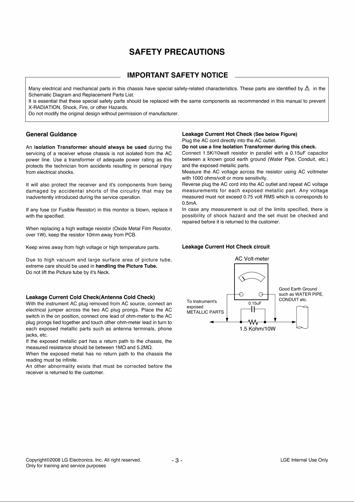
Leakage Current Hot
Plug the
Do
not
use
Connec! 1.5K/10watt resistor
AC
between a known good earth ground (Water Pipe, Conduit, etc.)
and the exposed metallic parts.
Measure the AC voltage across the resistor using AC voltmeter
with 1000 ohms/volt or more sensitivity.
Reverse plug the AC cord into the
measurements
be
measured must not exceed 0.75 volt
0.5mA.
ln
it
case any measurement
possibility of shock hazard and the set must be checked and
repaired before il
Leakage Current Hot
as
AC
cord directly into the
recommended
Check
in
this manual to prevent
(See below Figure)
AC
outlet.
a line Isolation Transformer during this check.
in
parallel with a 0.15uF capacitor
AC
outlet and repeat
for
each
is
returned
exposed
is
to
Check
AC
Volt-meter
metallic
RMS
out of the limits specified, there is
the customer.
which
part.
is
corresponds to
circuit
.&
AC
Any
in
the
voltage
voltage
Leakage Current Cold Check(Antenna Cold Check)
With the instrument
electrical jumper across the two AC plug prongs. Place the
switch
in
the
plug prongs tied together and touch other ohm-meter lead
each exposed metallic parts such as antenna terminais, phone
jacks, etc.
If the exposed metallic part has a return path
measured resistance should be between 1
When the exposed metal has
reading must be infinite.
An other abnormality exists that must be corrected before the
is
receiver
Copyright©2008
Only for training
returned
AC
plug removed from
on
position, connect one lead of ohm-meter to the
no
return path to the chassis the
to
the customer.
LG
Electronics.
and
service purposes
Inc.
AC
MO
Ali
right reserved.
source, connect an
to
the chassis, the
and 5.2MO.
AC
AC
in
turn
to
Good Earth Ground
such as WATER PIPE,
To lnstrument's
exposed D
METALLIC PARTS
~/\/\.--------..~
1.5
0.15uF
Kohm/1
- 3 -
CONDUIT etc.
OW
LGE
Internai
Use
Only
SPECIFICATIONS
NOTE : Specifications and others are subject to change without notice for improvement.
• Application Range
This spec is applied to the 42"
Chassis Model Name Market
PD83A 42PG3000 Austria, Belgiu
• Specification
Each part
1)
2) Relative Humidity: 65±10%
3) Power Voltage: Standard Input voltage (100-240V-, 50/60Hz)
4) Specification and performance of each parts are followed each drawing and specification by part number
5)
is
tested as below without special appointment.
Temperature : 25±5°C (77±9°F), CST : 40±5
* Standard Voltage of each product is marked by models.
The receiver must be operated for about 20 minutes prior to the adjustment.
PLASMA
TV used PD83A Chassis.
m,
Bulgaria, Coratia,Czech, Den mark, Fin land,
France,Germany,Greece,Hungary,ltaly,Luxembourg,
Netherlands,Norway,Poland,Portugal,Rumania,Russia,Ser
bia,Slovenia,Spain ,Sweden,Switzerland, UK
Brand
LG
in
accordance with SBOM.
Re
mark
• Test Method
1)
Performance : LGE TV test method followed.
2) Demanded other specification
Safety : CE, IEC specification
EMC : CE, IEC
Model Market
42PG3000-ZA Austria,Belgium,Bulgaria,Coratia,Czech,Denmark,Finland
,France,Germany,Greece,Hungary,ltaly,Luxembourg,
Netherlands, Norway, Poland, Portugal,
Serbia,Slovenia,Spain,Sweden,Switzerland,UK
Ru
mania, Russia,
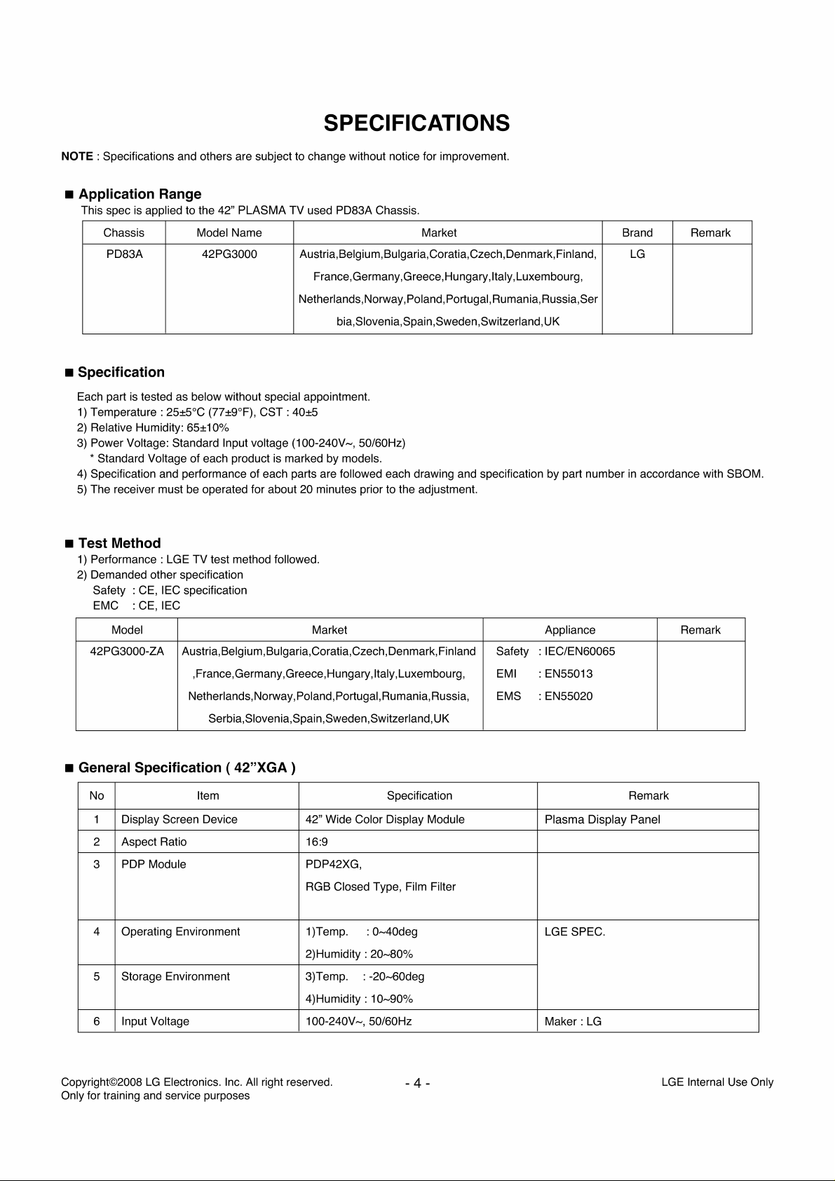
• General Specification ( 42"XGA )
No Item Specification
1 Display Screen Device 42" Wide Color Display Module
2 Aspect Ratio 16:9
POP Module PDP42XG,
3
RGB Closed Type, Film Filter
4 Operating Environment 1)Temp. :
2)Humidity :
Storage Environment 3)Temp.
5
4)Humidity:
6 Input Voltage 100-240V-, 50/60Hz
0-40deg
20-80%
:-20-60deg
10-90%
Appliance
Safety : IEC/EN60065
EMI : EN55013
EMS : EN55020
Plasma Display Panel
LGE SPEC.
Maker:
LG
Re
mark
Re
mark
Copyright©2008
Only for training and service purposes
LG
Electronics. Inc. Ali right reserved.
- 4 -
LGE Internai Use Only
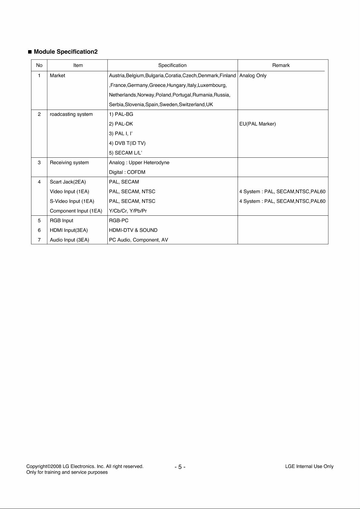
• Module Specification2
No Item Specification
Bu
1 Market Au stria, Belgium,
,France,Germany,Greece,Hungary,ltaly,Luxembourg,
Netherlands, Norway, Po land, Portugal,
Serbia,Slovenia,Spain,Sweden,Switzerland,UK
2 roadcasting system 1) PAL-BG
2) PAL-DK
1,
3) PAL
4) DVB T(ID TV)
5) SECAM
Receiving system Analog : Upper Heterodyne
3
Digital : COFDM
4 Scart Jack(2EA) PAL, SECAM
(1
Video Input
S-Video Input
Component Input
RGB Input RGB-PC
5
HDMI lnput(3EA) HDMI-DTV
6
EA) PAL, SECAM, NTSC
(1
EA) PAL, SECAM, NTSC
(1
EA) Y/Cb/Cr, Y/Pb/Pr
I'
7 Audio Input (3EA) PC Audio, Component,
lgaria, Coratia,Czech, Den mark, Fin land
UL'
& SOUND
AV
Ru
mania, Russia,
Re mark
Analog Only
EU(PAL Marker)
4 System : PAL, SECAM,NTSC,PAL60
4 System : PAL, SECAM,NTSC,PAL60
Copyright©2008
Only for training and service purposes
LG
Electronics. Inc. Ali right reserved.
- 5 -
LGE Internai Use Only
ADJUSTMENT INSTRUCTION
1.
Application Object
These instructions are applied all of the 42" PLASMA TV,
PD83A Chassis.
2.
Note
(1)
Because this
an isolation transformer. However, the use of isolation
transformer will help protect test instrument.
(2)
Adjustment must
(3)
The adjustment must be performed
25±5°C of temperature and 65±10% of relative humidity
there
is
(4) The input voltage of the receiver must keep 100-240V-,
50/60Hz.
(5)
The receiver must
to the adjustment.
ln
case of keeping module
should be placed
2hours.
ln
case of keeping module
C,
-20°
15°C for 3hours.
• Alter RGB Full white HEAT-RUN Mode, the receiver must
be operated prior
• Enter into HEAT-RUN MODE
1)
Press the POWER
2)
OSD display and screen display PATTERN MODE.
* Set
is
activated HEAT-RUN without signal generator
this mode.
* Single color pattern(RED/BLUE/GREEN) of HEAT-RUN
mode uses
If you turn on a still screen more than 20 minutes, (Especially
digital pattern, cross hatch pattern) alter image may be occur
the black level part of the screen.
3.
AOC Calibration
* Using 'power on' button off the contrai R/C, power on TV.
• Auto adjustment Map(RS-232C)
NO Item CMD1 CMD2 Data o
ADC adjust
Data Read
Default Write
Enter
Adjust Mode
ADC
ADC
Adjust Mode
Adjust Mode Out
- Baud : 115200bps, RS232 Host :
is
nota
hot chassis, it
be
done
in
no specific designation.
be
operated for about 15 minutes prior
in
the circumstance of above 15°C for
it should be placed
to
adjustment.
ON
KEY
to
check PANEL.
ADC
ad1ust
Parameter
Digital Data
Parameter
(Average)
Ad1ustment
Confirmation
A D 1
A D 2
A
A D
A D
A D 0 0
ln
A
D
D
is
not necessary
the correct order.
in
the circumstance of
is
in
the circumstance of
is
in
the circumstance of below
in
the circumstance of above
on
R/C for adjustment.
mark
Re
0
0
Transfer
1 BByte
(Input resolution Data)
0
3
4 0
To
check
ADC
Assembly
transfer
Adjustment
the
command.
9 9
9 0
PC,
Echo : none.
on
When
ln', Carry the
to
0°c, it
in
line
'Mode
use
in
4.
AOC adjustment
ADC Component
Model : 209(480i 60Hz)
MSPG925FS 223(1080i 60Hz)
Pattern : 65 Pattern : 65
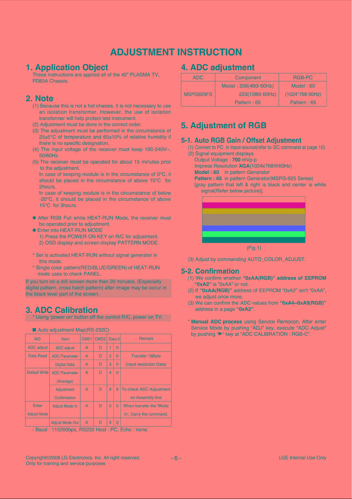
5.
Adjustment of RGB
if
5-1.
Auto
RGB
Gain I Offset
(1)
Convert
to
PC
in
lnput-source(refer
(2)
Signal equipment displays
Output Voltage : 700 mVp-p
lmpress Resolution XGA(1024x768@60Hz)
in
Model : 60
Pattern : 65
pattern Generator
in
pattern Generator(MSPG-925 Series)
[gray pattern that left
signal(Refer below picture)].
(3)
Adjust by commanding AUTO_COLOR_ADJUST.
5-2. Confirmation
(1)
We confirm whether "OxAA(RGB)"
is
"OxAA"
"OxA2"
(2)
If
"OxAA(RGB)" address of EEPROM
we adjust once more.
(3)
We can confirm the
address
in
* Manual ADC
Service Mode by pushing "ADJ" key, execute "AOC Adjust"
by pushing
"~"
or not.
AOC
a page "OxA2".
process
key at "ADC CALIBRATION: RGB-C".
RGB-PC
Model:
60
(1024*768 60Hz)
Adjustment
to
12C
command
& right
is
black and center
1)
(Fig.
address
"OxA2"
values from
"OxA4-0xA9(RGB)"
using Service Remocon. After enter
at
page 1 O)
is
of
EEPROM
isn't
white
"OxAA
",
Copyright©2008
Only for training
LG
Electronics.
and
service purposes
Inc.
Ali
right
reserved.
- 6 -
LGE
Internai
Use
Only
6.
Component input AOC
6-1. Component Gain/Offset Adjustment
(1)
Convert
to
PC
in
lnput-source(refer
(2) Signal equipment displays
lm
press Resolution 480i
1)
in
Model : 209
Pattern : 65
2) lmpress Resolution 1080i
Model:
Pattern : 65
223
pattern Generator(480i Mode)
in
pattern Generator(MSPG-925 Series)
in
pattern Generator(1080i Mode)
in
pattern Generator(MSPG-925 Series)
(Fig.2)
to
12C
command
at
page 1 O)
6-2. Confirmation
(1) We confirm whether "OxB3(480i)/OxBC(1080i)" address
of
EEPROM
If
"OxB3(480i)/OxBC(1080i)" address of EEPROM "
(2)
isn't "
We
(3)
"OxAD-OxB2(480i)/OxB6-BB(1080i)" address
"OxA2".
"OxA2"
OxAA",
we adjust once more.
can
confirm
is "OxAA
the
" or not.
ADC
values
in
OxA2"
from
a page
Each PCB assembly must be checked by check JIG set.
(Because power PCB Assembly damages to PDP Module,
especially be careful)
7.
POWER PCB Assy Voltage
(Va,
Vs
Adjustments
7-1. Test
Equipment:
Voltage adjustments)
D.M.M.1EA
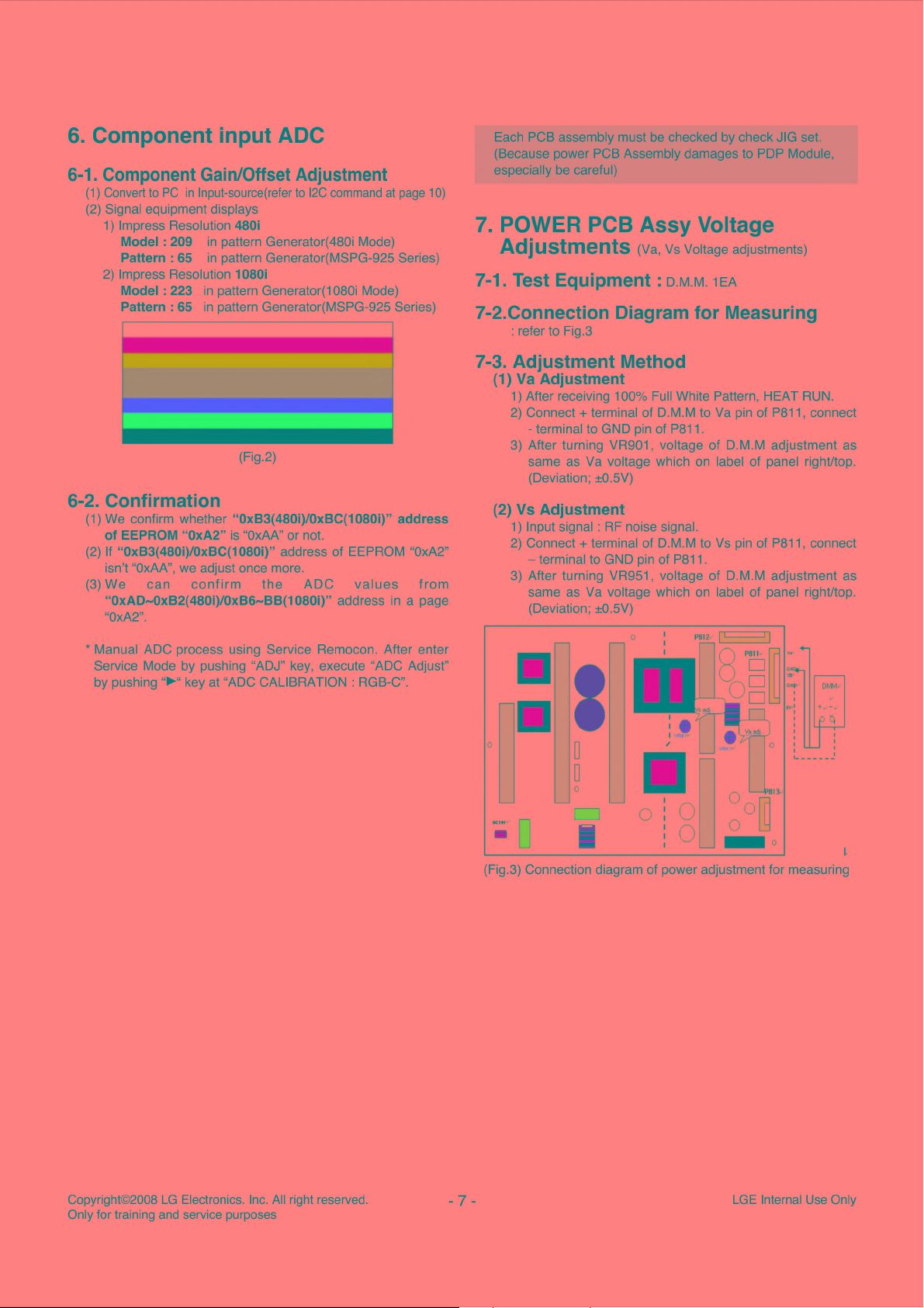
7-2.Connection Diagram for Measuring
: refer to Fig.3
7-3. Adjustment Method
(1) Va Adjustment
1)
Alter receiving 100% Full White Pattern, HEAT RUN.
2)
Connec!+
- terminal to GND pin of P811.
3) Alter turning VR901, voltage of D.M.M adjustment as
same as Va voltage which on label of panel right/top.
(Deviation; ±0.5V)
(2)
Vs
Adjustment
1)
Input signal : RF noise signal.
2)
Connec!+
~
terminal to GND pin of P811.
3) Alter turning VR951, voltage of D.M.M adjustment as
same as Va voltage which on label of panel right/top.
(Deviation; ±0.5V)
terminal of D.M.M to Va pin of P811, connect
terminal of D.M.M to Vs pin of P811, connect
* Manual ADC process using Service Remocon. Alter enter
SeNice Mode by pushing "ADJ" key, execute "ADC Adjust"
".,._"
by pushing
key at "ADC
CALIBRATION:
RGB-C".
•
1
•
•
(Fig.3) Connection diagram of power adjustment for measuring
D
D
Copyright©2008
Only for training
LG
Electronics.
and
service purposes
Inc.
Ali
right reserved.
- 7 -
LGE
Internai
Use
Only
8.
ED I D(The
/DDC(Display
Extended Display Identification Data )
Data Channel) download
8-5. EDID
1)
Analog-RGB.
DATA
8-1. Required Test Equipment
(1) Adjusting
(S/W : EDID TESTER Ver.2.
(2) A Jig for EDID Download.
(3) Cable : Serial(9Pin or USB) to D-sub 15Pin cable, D-sub
15Pin cab le,
PC
with S/W for writing EDID Data.
5)
DVI
to H
DMI
cable.
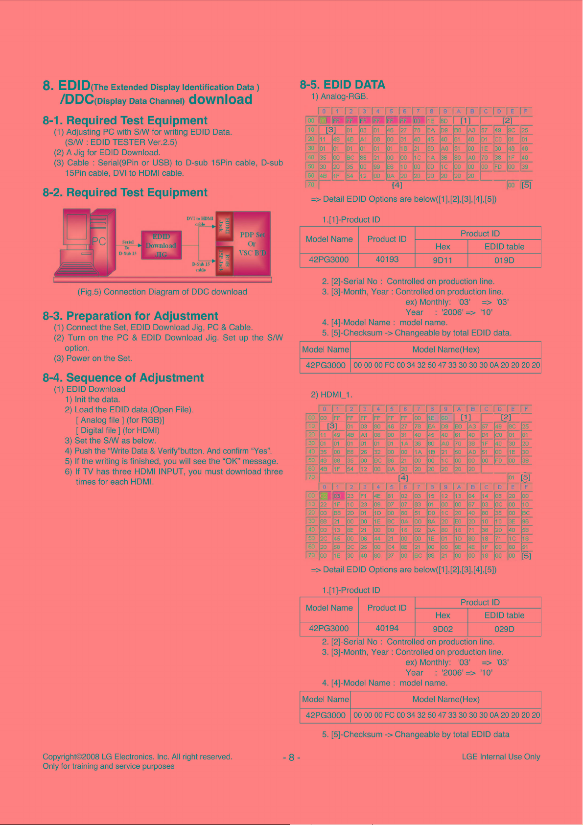
8-2. Required Test Equipment
(Fig.5) Connection Diagram of DDC download
8-3. Preparation for Adjustment
(1) Connect the Set, EDID Download Jig, PC & Cable.
(2) Turn on the
PC
& EDID Download Jig. Set up the S/W
option.
(3) Power on the Set.
8-4. Sequence of Adjustment
(1) EDID Download
1)
lnit the data.
2) Load the EDID data.(Open File).
[ Analog file
[ Digital file] (for HDMI)
3) Set the S/W as below.
4)
Push
5)
If
the writing
6)
If
TV has three HDMI INPUT, you must download three
times for each HDMI.
J (for RGB)]
the "Write Data & Verify"button.
is
finished, you will see the "OK" message.
And
confirm
"Yes".
01
5C
86
21
35
00
99
5,
12
)0
C.."
20
,[4]
=>
Detail EDID Options are below([1],[2],[3],[4],[5])
1.[1
]-Product
Model Name Product
42PG3000
2.
[2]-Serial
3.
[3]-Month, Year : Controlled
ID
ID
40193
No
: Controlled on production line.
Product
Hex
9D11
on
production line.
1
1
ex) Monthly: '03'
Year : '2006'
4.
[4]-Model Name : model name.
5.
[5]-Checksum -> Changeable by total EDID data.
=>
Model Name Model Name(Hex)
42PG3000
00 00 00
FC
00
34
32
50
47
33
30 30 30
2) HDMl_1.
[2]
00 (5]
ID
EDID table
0190
=>
'03'
'10'
OA
20 20 20 20
D F
1§']
57
8 8C 25
CO
Oi
F 40
~o
CO
1E
ü[,
00
rD
c·
01
20
30
39
[2]
Copyright©2008
Only for training
LG
Electronics.
and
service purposes
Inc.
Ali
right reserved.
=> Detail EDID Options are below([1],[2],[3],[4],[5])
1.[1]-Product ID
Model Name Product ID
42PG3000
2.
[2]-Serial No : Controlled on production line.
3.
[3]-Month, Year : Controlled on production line.
40194
9D02
ex) Monthly: '03'
Year : '2006'
4. [4]-Model Name : model name.
Model Name Model Name(Hex)
42PG3000
00 00 00
FC
00
34 32
50
5. [5]-Checksum -> Changeable by total EDID data
- 8 -
Hex
47
33 30 30 30
Product
1
1
=> '03'
=>
'1
LGE
Internai
ID
EDID table
029D
O'
OA
20 20 20 20
Use
Only
2)
HDMl_2.
=>
Detail EDID Options are below([1 ],[2],[3],[4],[5])
* Please refer HDMI_
3) HDMl_3 .
1.
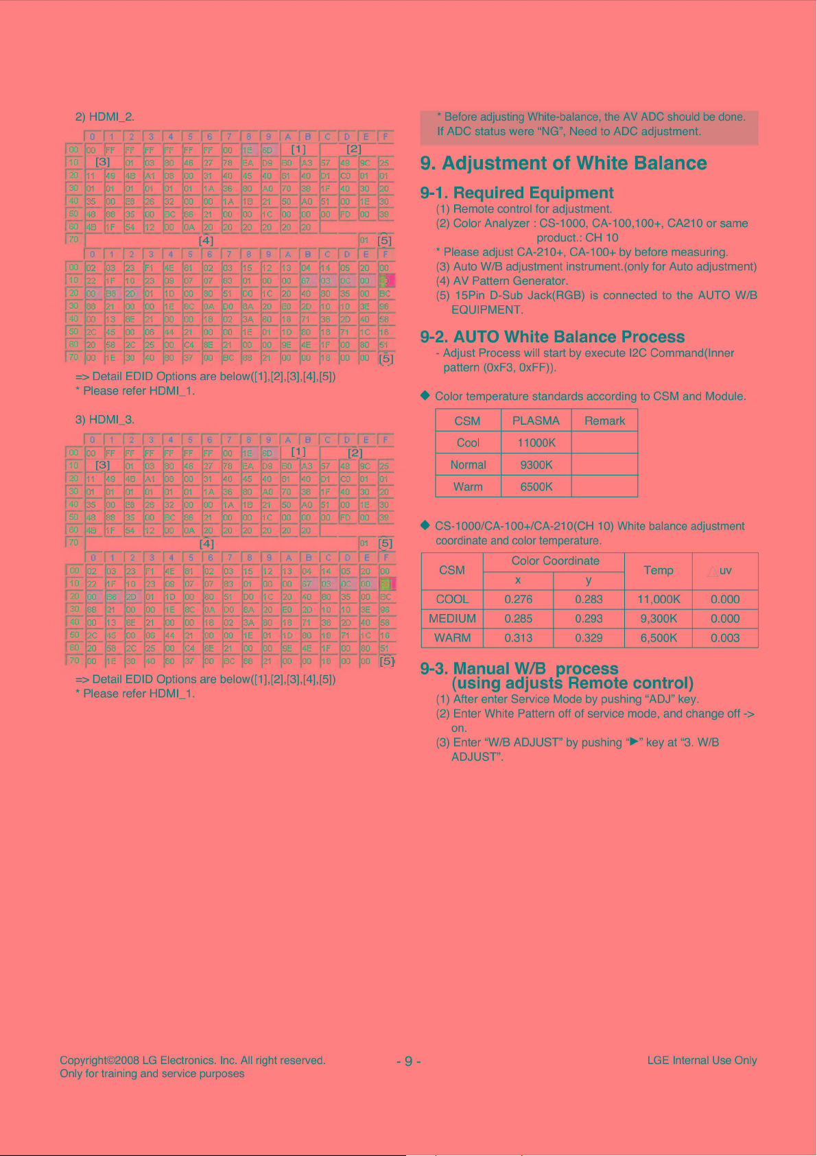
* Before adjusting White-balance, the AV
If AOC status were "NG", Need to AOC adjustrnent.
9.
Adjustment of White Balance
AOC
should be done.
9-1. Required Equipment
(1) Remote contrai for adjustment.
(2) Color Analyzer : CS-1000, CA-100, 100+, CA210 or same
product.: CH 10
* Please adjust CA-210+, CA-100+ by before measuring.
(3) Auto W/B adjustment instrument.(only for Auto adjustment)
(4) AV Pattern Generator.
(5) 15Pin D-Sub Jack(RGB) is connected to the AUTO W/B
EQUIPMENT.
9-2. AUTO White Balance Process
- Adjust Process will start by execute
pattern (OxF3, OxFF)).
• Color temperature standards according to GSM and Module .
CSM
Cool 11000K
Normal 9300K
Warm 6500K
PLASMA
Re
mark
12C
Command(lnner
=> Detail EDID Options are below([1],[2],[3],[4],[5])
* Please refer
HDMl_
1.
• CS-1000/CA-1
coordinate
CSM Temp
COOL 0.276 0.283 11,000K
MEDIUM 0.285 0.293 9,300K
WARM 0.313 0.329 6,500K
OO+/CA-21
and
color temperature.
Color Coordinate
X
O(CH
10) White balance adjustment
y
9-3. Manual W/B process
(using adjusts Remote contrai)
(1) Alter enter Service Mode by pushing "ADJ" key.
(2) Enter White Pattern off of service mode, and change off
on.
(3)
Enter "W/B ADJUST" by pushing
ADJUST".
"~"
key
al
"3. W/B
UV
0.000
0.000
0.003
->
Copyright©2008
Only for training
LG
Electronics.
and
service purposes
Inc.
Ali
right reserved.
- 9 -
LGE
Internai
Use
Only

9-4. Connection Picture of the Measuring
lnstrument(On Automatic contrai)
(1) lnside PATTERN is used when W/B
or
to auto controller
the mode
of
push control R/C IN-ST
White-Balance , the pattern will corne out.
is
controlled. Connect
ART->
Enter
12. EEPROM DATA READ
12-1. Single TABLE
ISTARTI
~
0~
0
ŒJ
Delay
IOOms
0 ~ 0
~0~0
~ 0 ~
01
STOP
1
Full
White
Pattern
RS-232C
Communication
(Fig.6) Auto AV(CVBS) Color Balance Test Pattern
l
CA-210
Col
ANALYZER
TYPE·
or
CA-210
9-5. Auto-contrai interface and directions
(1) Adjust
(2) Measure and adjust after sticking the Color Analyzer(CA-
(3) Aging time
in
the place where the influx of light like floodlight
Jess
around is blocked.(illumination is
100+, CA210) to the side
- After aging start, keep the power on(no suspension of
power supply) and heat-run over 15minutes.
- keep white pattern using inside pattern.
of
the module.
than 10ux)
• Auto adjustment Map(l2C)
-
12C(1
OOK
BPS)
1
O.
Communication START
1
START
* Until
I l 6E 1 1 A 1 1
ACK
BIT goes LOW, Repeat it.
STOP
I l
soMs
1
11. Command form
• Command form use DDC2AB standard communication
protocol.
lsTARTll
sEIIAllsollAIILENIIAllo311AII
1.
LEN:
DATA BYTE
2.
CMD : Command language that monitor executes.
3.
VAL:
FOS DATA
4.
CS : Dada's CHECKSUM that transmit.
5.
DELAY:
6.
A : Acknowledge.
50MS
CMoll
numberto
AlloollAII
send.
VALIIAllcsllAII
STOP
12-2. Command Set
Adjustment CMD
No .
contents (hex)
1 EEPROM READ
2
3
4
5
6
7
8
* To read the appointment Address of
byte
13. EEPROM Data
ADH
(hex)
E?
AO
A2
A4
A6
Write(Serial
ADL
(hex)
0 0-page
80
0
80
0
80
0 3-page
80
13-1. Signal TABLE
1 CMD I LENGTH I ADH I ADL I
CMD
LENGTH : 84h+bytes
ADH : E2PROM Slave Address(AO,A2,A4,A6,A8)
ADL : E2PROM Sub Address low (00-FF)
Data : Write data
CS :
1
:8Eh
Not OOh(Reserved by Buffer To EEPROM)
CMD
+ LENGTH +
DATA_11
ADH + ADL
... 1 DATA_n I CS
13-2. Command Set
No
1
2
EEPROM
Adjust mode
CMD(hex) LENGTH(hex) Description
WRITE
E8
94 16-Byte Write
84+n
0-page
1-page
1-page
2-page
2-page
3-page
E'PROM
+ Data_ 1 +
n-Byte Write
Details
0-?F
80-?F
0-?F
80-?F
0-?F
80-?F
0-?F
80-?F
by 128(80h)-
No
D/L)
I DELA
...
+ Data_n
Read
Read
Read
Read
Read
Read
Read
Read
YI
LG
Copyright©2008
Only for training and service purposes
Electronics.
Inc.
Ali
right reserved.
*
Description
FOS
Default
write : <?mode
Violai, V
_Frequency,
Data
write:
Madel
Name
13-3. Method & Notice
(1) Se rial number D/L is using of scan equipment.
(2) Setting of scan equipment operated by Manufacturing
Technology Group.
(3) Serial number D/L must be conformed when it is produced
in
production line, because serial number D/L
by D-book 4.0.
-
10
-
data>
Sync_Polarity,
and
Serial
write
Htotal,
Number
Hstart,
write
LGE
Vstart,
in
EEPROM,
Internai
0,
Phase
.
is
mandatory
Use
Only

14. Adjustment Command(LENGTH=84)
No
1 FACTORYON
2 FACTORYOFF
3
4 EEPROM Read E7
5
6
7 H POSITION 20
8 V POSITION 30
9
10
11
12 G DRIVE
13 B DRIVE 10
14 R CUTOFF
15 G CUTOFF
16 B CUTOFF
17 BRIGHT
18 CONTRAST
19 AUTO_COLOR_ADJUST
20
21
22
Adjustment Contents CMD(hex)
EO
E2
EEPROM ALL INIT. E4
EEPROM Write
COLORSAVE
(R/G/B cutoff, Drive,
Contrast, Bright)
CLOCK
PHASE 92
R DRIVE 16
CHANGE_COLOR_TEMP
White Pattern
AUTO_INPUT CHANGE
ES
EB
90
18
1A
80
82
84
12
F1
F2
F3
F4
ADR VAL[HEX]
00 00
00 00
00 00
00 00
00 data
00 00
00
00
00
00
00:
cool
01: medium
02:
warm
00:
cool
01:
medium
02:
warm
00 :cool
01: medium
02: warm
00
00
00
00
00
00 02
00
00
00
0,
00-64
00-64
00-64
00-64
00-80
00-80
00-80
00-7F
00-7F
00-7F
00-3F
00-64
0,1,2,3
00,FF
10,20,30,
40,60,90
Description
Factory mode on
Factory mode off
EEPROM Ali clear
EEPROM Read
EEPROM Write by some values
Color Save
They have different range each mode,
FOS Adjustment
Drive adjustment
Offset adjustment
Bright adjustment
Luminance adjustment
Auto COLOR Adjustment
O: Cool
1 : Medium
2:
Warm
3:
User
00: White pattern off
FF: White pattern on
: TV
0
10:
DTV
20:
SCART1
30:
SCART2
40 : Component
60:
RGB
90:
HDMI
Copyright©2008
Only for training
LG
Electronics.
and
service purposes
Inc.
Ali
right reserved.
LGE
Internai
Use
-
11
-
Only

15.
Set
lnformation(Serial
15-1.
Check
(1) Push the menu button in
- Select the
the
STATION->
serial
Diagnostics->
No & Model
number & Model
DTV
mode.
To
set.
name)
name
16. SET factoring condition
(1) This
adjustment
(2) Push
the IN-
the factory shipment.
is setting factory
STOP
key
of
shipment
adjustment
remote controller before
mode.
(2)
Check
~
the Serial
CH
34
CH
36
CH
38
54
.....
Number
No
Power Off
1
Volume Level
2
Main Picture Input
3
Main Las! Channel
4
Mute Off
5
ARC 16:9
6
SETUP
7
(DTV&ATV) Manual Tuning
,.
••
___
.
@
PICTURE Aspect Ratio
8
AUDIO Auto Volume Off
9
Time Clock
10
OPTION Menu Lanquaqe
11
LOCK Lock System Off
12
Item
Auto Tuninq
Proqramme Set
Booster
Software Update
Diagnostics Engineering
Cl Information
Picture Mode Vivid 100
Balance
Sound Mode
Off time Off
Ontime
Sleep Timer
Auto Sleep Off
Time zone
Audio Lanquaqe
Lançiuaçie
Subtitle
Hard of hearinq
Country
Input label
KeyLock
ID
Set
Factorv Reset Off
Set Password New
Block Proqram TV /DTV /Radio
Parental Guidance Off
Condition
15
Antenna
NA
ON
OFF
Diaqnostics
16
:9
Contras!
Briqhtness
Col or
Sharpness
Tint ColorTemp
Advanced Control Fresh Con.
Picture reset
0
Standard 120Hz
--
--
Off
Off
Off
Off
1
* * * *
Confirm
* * * *
Re mark
DTV&ATV
50
60
50
Fresh col.
Noise
Reduction
Film (3:2)
Black level
200Hz
500Hz
1.2Khz
3Khz
7.5Khz
12Khz
User contrai
0
Medium
On
On
On
Off
50
50
50
50
50
50
50
Copyright©2008
Only for training and service purposes
LG
Electronics. Inc. Ali right reserved.
- 12 -
LGE Internai Use Only


(4) Click "Read" tab, and then load download file(XXXX.bin)
by clicking "Read"
JI
D~ • ~,G
V.
·-,el
•
11
D
2. USB DOWNLOAD
- Put a * .bin to USB Stick and Tu
(1) Put the USB Stick to the USB socket
rn
on TV
~
Checksum
u
....
,cd8.,tu
'""
• ~
111
..
'.:l·
'.
1_:
)L
lSP
'
6
~
~
Co
nfig
Re
sto
re
HDCP
Era
se
m
Connec! D1s
Flash_J
Pass
F
lash
Stat
USB
3J5t'.Hz
~~~~
us:
~~~
~~
,.
w.,~
(5) Click "Auto" Button, select the check box, and then Click
"Run" Button.
D
evic
e L
oad
Read AUto 8 P V
~
G)ReadFile
Ghects
R
Multi Flashes
oileArea
1 Elapsed
eGonnect
um.
estore
Data
AIICh
ip
EraseAr
Partial Erase
Time: 04.1
~~~~~~~~~~~~~
: OzB43 4
ea
1 1
Blank
(E)Progra
Veri(y
(2)
En t
2C
(6) After downloading, check "OK" message.
in
(2) Automatically detecting update file
* If your downloaded program version
USB Stick
in
USB Stick is Low,
it didn't work.
But
your
downloaded
ver
sion
is
High, USB
data
is
automatically detecting .
(3) Show the message "Copying files from memory"
9
Con
(4) Updating is staring.
(5) Updating Completed, The TV will restart automatically.
After tu
rn
on TV, Please press 'IN-STOP' button on ADJ
Remote-control.
IF
you don't have ADJ R/C,
*
enter 'Fac
tory
Reset' in
OPTION MENU.
When
TV
(6)
turn on,
check
the
Updated
version
on
Diagnostics MENU.
lC
(7) Updating Completed, The TV will restart automatically.
After turn on TV, Please press 'IN-STOP' button on ADJ
Remote-control.
* IF you
don't
hav
e ADJ R/C,
enter
'Factory
Reset'
OPTION MENU.
(8) When
on, check the
Updated
version
TV
turn
Diagnostics MENU.
E~GINEERING JIAGNOSTICS
CH0028
CH
00111
CHOOJO
CH0031
in
on
Copyright©2008
Only
for
training
LG Elec
tronics.
and
service purposes
Inc.
Ali rig
ht reserved.
- 14 -
LGE
Int
ernai Use Only

1. Power Board
TROUBLE SHOOTING GUIDE
1-1. The whole flowchart which it follows
Start check
Doesn't the
screen whole corne
out?
No
Doesn't the Yes No No
low pressure output
corne out?
No
Yes
•
>---------••<
ls it identical
with Power Off
1 . Check the Power Off
condition.
3. Check the St-by 5V 4. Check the
signal circuit. signal circuit. signal.
in
voltage output state
No
ls the Interface
signal operated?
2.
Check the Interface
signal condition.
5V
Monitor
5.
Check the VSC RL-ON
Doesn't the
high tension output
corne out?
No
Does
high tension
output voltage
occur?
No
Manufacture enterprise
rneaning of a passage
DroR
Yes
•
7.
Yes
________.
does
Check the VSC Vs-ON
signal
Whenthe
Y, Z B/D
input
Power
output voltage
9.
Board Output high
Module
connector
Yes •
Check the Power
tension circuit
Board
occur?
is
remove,
hightension
Drop
No
8.
Check the Vs, Va
voltage output circuit.
No
------>-
Doesn't the
input connector is
removed, does outpu
voltage drop
occur?
Yes+
10. Check the Z B/D
Module output circuit
Doesn't the
VSC low pressure
output corne out?
6.
Check the VSC low
pressure output
No
input
removed,
11
. Check the Y B/D
Module output circuit
hen
Z
B/D
connector
voltage
ccurs?
Yes +
th
Module
does
Drop
No
is
output
Copyright©2008
Only for training
LG
Electronics.
and
service purposes
Inc.
Ali
right reserved.
- 15 -
LGE
Internai
Use
Only

1-2. 42" Power Board Structure
0
liCtll
-
0
D
0
0
rr
• ~
/
P812 ,
,.._
__
__.
(..-...)
o
P8l
l
§s
( D
wl
lll
_Q
·ad
0
1
1 1
·------
813
or
_)
0
rn
- 0
DMM
+ -
-
P811
P812
V
-S
V-S
NC
GND
GND
V-A
V-A
GND
M
SV
MSV
V
-S
V-S
NC
GND
GND
V-A
V-A
GND
M
SV
MSV
IDDDDDDD
1 2 3
I
Copyright©2008
Only for training and service purposes
LG
Electronics. Inc.
Ali
right reserved.
- 16 -
LGE Internai Use Only

2. No Power
(1) Symptom
1)
Doesn't minute discharge at module.
2) Non does not corne
(2) Check following
in
into the front LED.
0
ls plug
in
power cord?
~~~~~~~~~~~~~
i
Yes
ls the Line Filter and Power
Board Cable connected?
tes
ls the Fuse(F801) on
Power Board normal?
tes
ls the Power Board and 22P of
VSC Board Cable connected?
tes
After the cable connect is removed
to Power Board, authorized the AC
voltage marking on manual.
When ST-BY 5V is not operated,
replace Power Board.
1--------
------------------->
------------------->
No
_________ > Plug
No
No
No
in
power cord.
Connectthe
Replace the Fuse.
Cable.
------------------> Connec! the Cable.
Copyright©2008
Only for training
LG
Electronics.
and
service purposes
Inc.
Ali
right reserved.
- 17 -
LGE
Internai
Use
Only

3.
Protect Mode
(1) Symptom
1)
After once shining,
from module.
2)
The Rely falls.(The sound
3)
lt
is
converted with the color where the front LED
is
red
from green.
(2) Check following
it
does not discharge minutely
is
audible "click")
•
ls the Power Board
normal?
t Yes
ls
the each connector
normal?
t Yes
ls the Y-Board
normal?
t Yes
ls the Z-Board
normal?
t Yes
ls
the X-Board
normal?
t Yes
ls
the Ctrl Board
normal?
No
----•
No
----•
No
----•
No
----•
No
----•
No
----•
ls
output the normality Low/High
voltage except Stand-by 5V?
Alter connecting well each connector,
the normality it operates?
ls
the Fuse(FS202)
normal?(ln case of open
ls
the output voltage alter remove
P801
connect of Z-B/D normal?
ls
the output voltage normal alter
remove P211,
X-B/D?
ls
the output voltage normal alter
remove P161, P162 connector of Ctrl-
P311
B/D?
on
Y-B/D
is
replace)
connector of
__
~-o-
• Replace Power
Yes
..
Yes
Yes
ls the output voltage
normal after remove
..
P201
..
After remove
Yes
Yes
Replace Right X-B/D
..
Alter remove
Replace Left X-B/D
..
Board.
Replace the
connector.
connector of
Y-B/D?
Replace
Z-Board.
Replace
X-Board.
Yes
..
P311
output voltage normality:
P211
output voltage normality:
Replace
Y-Board.
VSC Board normal?
ls
the COF of
Copyright©2008
Only for training
• Yes
ls the
t Yes
X,
normal?
LG
Electronics.
and
service purposes
Y,
----•
Z
----•
Inc.
No
No
ls
the output voltage normal after
remove P801?
Alter crisis COF of each board, check the normality operates.
If
in
case normality operates, correspondence COF Fail
Ali
right
reserved.
- 18 -
Yes
..
P801
After remove
operation: Replace VSC Board
is
replace the module.
normal
LGE
Internai
Use
Only

4.
No Raster
(1) Symptom
1)
No OSO and image occur at screen.
2)
lt
maintains the condition where the front LED
(2)
Check
following
is
green.
0
Does minute discharge
At Module?
Yes
1 f
ls the L VDC cable
normal?
Yes
1 f
ls the IC100(LGE7383C)
Output normal?
No
-----•
No
-----•
No
-----•
ls the VAVS on?
YES
Check the POP Module
Reconnect the L VOS
'
cable in P400
Replace the VSC.
NO
-----•
ls output the normality
Low/High voltage except
stand-by
SV?
NO Replace the Power
----•
board
Copyright©2008
Only for training
LG
Electronics.
and
service purposes
Inc.
Ali
right reserved.
- 19 -
LGE
Internai
Use
Only

5.
ln
case of occurring strange screen into specific mode
5-1.
ln
case the OSD does not displayed
(1) Symptom
1)
LED is green.
2) The minute discharged continuously becomes Accomplished from module.
(2) Check following
0
ls the L VOS cable
normal?
Yes
, ,
ls the VSC Board
normal?
Yes
, ,
ls the Ctrl Board of
Module normal?
No
-----•
No
-----•
No
-----•
ls the L VOS cable
connected?
:
No
1
1
Re-insert the Cable inserts.
Operates ?(LGE7383C)
'
Does the IC100
1
,
No
1
1
Replace IC100
'
(LGE7383C)
Replace Ctrl B/D.
Yes
Yes
..
Replace the cable.
-
Replace hte VSC B/D
Copyright©2008
Only for training
LG
Electronics.
and
service purposes
Inc.
Ali
right reserved.
LGE
Internai
Use
-
20
-
Only

5-2.
ln
case of does't display the screen into specific mode
(1) Symptom
1) The screen does not
(RF, AV, Component, RGB, DVI).
(2) Check following
1)
Check
the all input mode should become normality display.
(3)
ln
case of becomes unusual display from
ls the
Tuner
become
normal?
the display from specific input mode
No
--------
Yes
BlockA
RF
ls the
Tuner
1
f No
Re-insert the Cable .
mode
Cable connected?
i-
--
iil!
1
1 - -
1 - -
1 - jillll!illl
1 - - -
ls the Input voltage, IIC Communication
CVBS
and
output normal?
Replace the
No
Tuner
.
~'s_t_h_e_1c_1_o_o_(L_G_E_7_3_8_3_C_)
(4)
ln
ls the Video input
Jack(JK700, 707)normal?
(5)
ln
ls theR,G,B input and H,V Sync
normal? _ Communication? _
the case of becomes unusual display from side S-video/AV mode
of
• Yes
Same
as Black A
the case of becomes unusual display from Component, RGB mode
of the JK701,703 normal?
Yes
Same
as Block A
the
~
__
AV
- - - -
~~..,
~-ls_n_o_rm-al_t_h_e_ln_p_u_t
No
..,
Check
the input source and Cable
---~~---1
~-----------~
Check
the input source
_vo_l_ta_g_e_,
_11c_~- ___
-~~
___
..,
~I
__
R
__ i -~h-l~-~
ep
ace e ·
Copyright©2008
Only for training and service purposes
LG
Electronics.
Inc.
Ali
right reserved.
-
21
-
LGE Internai Use Only

(6) ln the case of becomes unusual display from HDMI mode
~1-s-th_e_v_id_e_o_in_p_u_to_f_t_he~--~~•~I
_ HDMI
~---n_o_rm_a_l?_.
Jack
normal? _
.Yes
ls the TDMS(IC902) No ls the Input and Output signal,IIC No 1
Same
.Yes
as
--~
Black A
- - - -
___
c_h_e_ck-th_e_in_p_u_t_so_u_rc_e
-•
'----C_om_m_u_n_ic_at_io_n_n_o_rm_al_?
__
__
(7) ln the case of becomes unusual display from SCART1 mode
ls the Video input od
Jack(JK601) normal? .
.Yes
Same
as
Black A
AN
--~-~•1
~-----------~
Check
the input source
~
_,
- - - - - -
-•
~--R_e_p_la_ce_th_e_i_c_. _ _.
(8) ln the case of becomes unusual display from SCART2 mode
ls the Video input od
Jack(J600) normal?
.Yes
Same
as
Black A
AN
--~-~•1
~-----------~
Check
the input source
Copyright©2008
Only for training and service purposes
LG
Electronics. Inc. Ali right reserved.
- 22 -
LGE Internai Use Only

6.
ln
case of
(1) Symptom
1)
LED is Green.
2) Screen display but sound
(2) Check following
no
sound
is
not output.
Yes
Ali input(mode) is no
sound?
________________________________
i No
Only HDMI is No
Sound?
Yes
-----.-
Download
the EDID data
i No
Only RF is no sound?
-----.-
the Tuner IN/OUT
Yes Check
i No
Only AV/component/PC
input is no sound? the Sound IN/OUT
-~-e~._
Check
ls the speaker On
._
ls the speaker Cable
normal?
IC1000 operates
menu?
i YES
Yes
normal?
it
No
-----.-
No
----.-
No
-----.-
Set on speaker
Check the Speaker
Cable.
Replace the IC1000
(NTP3000A)
in
menu.
Copyright©2008
Only for training
LG
Electronics.
and
service purposes
Inc.
Ali
right reserved.
- 23 -
Replace the VSC B/D
LGE
Internai
Use
Only

0
:::,
'<~
ô
~
-
el.@
:::,
-·
:::,
lO
m r
6.
(/)
(D
~
:S.
()
(D
TI
C
-a
0 -
(/):::,
(D
(/)
()
0
~-
lO
:::,-
[\.)
0
0
CD
G)
m
-
(D
Q.
~
0
~-
()
!'.fl
,,
~
(0
3:
iil
(/)
(D
<
(D
o.
1\)
+:>-
r
G)
m
:::,
iii
:l
flè.
C
(/)
(D
0
::,
'<
DTV/MNT V OUT
SC2
CVBS
IN
SC1_R/G/B
SC1_TV_VOUT
DSUB
..
R/G/B
DSUB_HIV
_SYNC
PC_UR_IN
-,
<
~
:,
1
CD
Il
[)
COMP _ Y/Pb/Pr
UR
1
IN
cEc
TMDS
HPD
COMP
~
rr~
• .
•
i.....!...
~EPROM 1 §PROM I IEEPROM
DTV/MNT
SC1_L/R_IN
@~
BOOSTER
AGC_SPEED
TV_CVBS
SIF
TU_TS
1
REMOTE
1, 2, 3
SC2
UR
IN
_L/R_OUT
SC1. CVBS
TV_LIR_OUT
IN
MM1731
(IC700)
0
1
DATA
GJ
r--
MDS351
(IC902)
___.
____.
!
PAG
OMS
PD
a....:._-----~
5V
..
_HDMl_
KIA7427
(IC101)
1
+
EEPROM
LGE7363C
(IC100)
_,()()({)
(/)
~
~
Ul"lH
1 1 1 1l
(/)
~
![
1
0
;i,-
;i,-0 '1l_
-, 0
~
i[
l
Cl
Slot
(PBOO
Cl
CD
,a1
-
Kl;7S232FU
1,
2,
3
(IC802)
Il
)
~
(IC302)
r
NTP300A
IC902
1
(/)
"
-
;i,-
i°
0
m
_
..,
~
C
-,
I11
in
:::
1
JJ
m
(/)
m
_
..,
()
>
P1100
iil
CSN
1
.iil
CSN
2
1
l~DATA[O
1 ~DATA[1731J
LED
G/R&l~1
KEY1/2
~
SIDE_
Y,
C_IN
SIDE_L,R_IN
SIDE
CVBS
USB
1
DM/DP
-!l~(L)
P1000
16]
~
IN
~I
Flash
Flash
~I
1
~
256Mb
~
1
256Mb
LVDS
LVA_ [0:4]
P401
SP
4MB
4MB
DDR
DDR
(R)
Memory
(IC303)
Memory
(IC304)
Memory
(IC300)
Memory
(IC301)
POP
Panel
1
ê
m
r
0
0
C
"
-
)>
C)
lJ
)>
s:

0
:::,
--o
'< '<
ô
~
~@
-·
~-
:::,
(0
m'
6.
(/)
(D (D
;;_
()
(D
TI
C
-a
0:::,
(/)
(D
(/)
()
0
t.6·
:::,-
[\.)
0
0
OJ
G)
IJJ
8-
0
:::,
o·
(f)
:_
()
.
~
(0
3:
iil
(/)
(D
<
(D
o.
1\)
(Jl
Power
P1100
+5V_ST(6A)
1•
0
MOSFET
(01102)
~---
POWER_
ON/OFF1
Stand-by
+5V
1
+5V_GENERAL
+5V_CI
AZ1085S-3.3V
IC1105
1
1+3.3V _ VDDP
Û
AZ1085S
IC1102
1
AZ1117D
(IC1103)
_ST
I +
1.25V _ST
1
+3.3V_TU 1 0.003
1
+3.3V_CI
5000hm
BEAD
AZ1117D
0.001
(IC1104)
AZ1117D
(IC1108)
A
A
1
+3.3V_VDDP
+3.3V _AVDD _MPLL
+3.3V_IR
+3.3V_AVDD_OTG
+3.3V _AVDD _ADC
+3.3V _AVDD _MEMPLL
+1
.25V_VDDC
+ 1.25V _AVDD _DVI
B
1
+1
.B_
AMP
1
G)
'
:::,
iii
:l
flè.
C
(/)
(D
0
:::,
-<'
m
1
li
11
P
12V(1A)
+16V(1.3A)
5000~m
BEAD
+12V_SC
1
KA7809ERTM
(IC1109)
1
KIA7805AF
(IC1110)
1
+5V_TU
1
AZ1117D
(IC1107)
1
+3.3V_AVDD_S1F
+3.3V
AVDD
+3.3V _AVDD _LPLL
AU
1
1
+3.3V _AVDD
1
+2.5V_DDR
+2.5V _ VDD_DDR
1
5000hm
BEAD
0.055
A
0.04A
1
IC1000(AMP)_PVDD

EXPLODED VIEW
Copyright©2008
Only for training and service purposes
LG
Electronics. Inc. Ali right reserved.
-
26
1~
'-
-
-
LGE Internai Use Only

SPDIF
OPTIC
.JACK
Cl
BUF
TS
CLKBUF
TS
DATA[O],BUF T SYNC,TU
ERROR & BUF
74LVC541A(PW)
ICSOO
+5V_CI_Vs
.
TS
VAL
TU
TS
DATA[1-7]
1
0067972-0SOLF
~rta,»_
PCM
D[3]
THEL§YMBOL
SPECIAL
FILRE
ESSENTIAL
THE
DDR
MARK
FEATURES
IMPORTANT
AND
ELECTRICAL
THAT
ONLY
CRITICAL
COMPONENTS
MEMORY
,go1
'I:1,
,;;T
T
sro sro
DQM1
M_WE
L...J-------,-+------,
M_CAS L...J-------,-+------,
M_RAS L...J-------,-+------,
OF
THIS
SCHEMETIC
FOR
PROTECTION
SHOCK
HAZARDS,
MANUFATURES
IN
TH~
,1, ,1, ,1, ,1, ,1,
GI° GI° GI°
+2.SV_DDR
IC300
DIAGRAM
INCORPORATES
FROM
WHEN
SERVICING
SPECFIED
PARTS
SYMBOL
MARK
OF
,L
b,
GI°sI;'"J'"'
X-RADIATION.
IF
IS
BE
USED
FOR
THE
SCHEMETIC.
+2.5V_DDR
1
mil = 0.0254
20
mil = 0.508
40
mil=
ADDRESS
TOTAL
DDR1 & DDR2
1.016
LENGTH < 3000
different
mm
mm
mm
mil
(76.2mm)
length
range=+/-
+2.5V_DDR +2.5V_DDR
25
mil
IC301
(max+/-
THEL§YMBOL
SPECIAL
FILRE
ESSENTIAL
THE
FEATURES
AND
ELECTRICAL
THAT
CRITICAL
MARK
OF
THIS
IMPORTANT
SHOCK
ONLY
MANUFATURES
COMPONENTS
SCHEMETIC
FOR
PROTECTION
HAZARDS.
SPECFIED
IN
TH~
SYMBOL
DIAGRAM
WHEN
PARTS
MARK
INCORPORATES
FROM
X-RADIATION
SERVICING
IF
BE
USED
OF
THE
SCHEMETIC
IS
FOR
HDMI
50
mil)
MADR[10J ,------,-------1---1--"=a
MADR[O]
,------,
__
MADR[1]
MADR[2]
MADR[3]
THEL§YMBOL
SPECIAL
FILRE
ESSENTIAL
THE
Copyright©2008 LG Electronics. Inc. Ali right reserved
Only for training and service purposes
____,-+------,
,------,-------,-+------,
=-------,-+------,
=-------,-+------,
MARK
OF
FEATURES
IMPORTANT
AND
ELECTRICAL
THAT
ONLY
CRITICAL
MANUFATURES
COMPONENTS
THIS
SCHEMETIC
SHOCK
IN
FOR
HAZARDS,
TH~
DIAGRAM
PROTECTION
WHEN
SPECFIED
PARTS
SYMBOL
MARK
INCORPORATES
FROM
X-RADIATION.
SERVICING
IF
BE
USED
OF
THE
SCHEMETIC
IS
FOR
MADR[10]
,-,_
MADR[O]
,-,_
MADR[1]
,-,_
MADR[2]
,-,_
MADR[3]
=,--------1-+-------,
___
W.::'.:":'.:'..!
___
I+-------,
___
I+-------,
___
I+-------,
THEL§YMBOL'"MARK
SPECIAL
FILRE
AND
ESSENTIAL
THE
CRITICAL
FEATURES
ELECTRICAL
THAT
ONLY
COMPONENTS
OF
THIS
SCHEMETIC
IMPORTANT
SHOCK
MANUFATURES
IN
FOR
PROTECTION
HAZARDS,
SPECFIED
TH~
SYMBOL
DIAGRAM
WHEN
PARTS
MARK
INCORPORATES
FROM
X-RADIATION.
SERVICING
IF
IS
BE
USED
OF
THE
SCHEMETIC.
FOR
+3.3V _ VDDP
_ST
LGE Internai Use Only

Module
001
·21D;001
:25l·009·10D
THE2'sYMB0L
SPECIAL
FILRE
ESSENTIAL
THE
SW
SDA
3.3V
001
17ALLVA_OP
001.16ALLVA
001.16AL
LVA_2
001·1sL>.lVA_CKP
001:15ALLVA
001·15ALLVA_4P
PC_SER_DAT
FEATURES
AND
ELECTRICAL
THAT
CRITICAL
R40Q
100
1P
p
3P
oom
t
R401
MARK
OF
THIS
SCHEMETIC
IMPORTANT
SHOCK
ONLY
MANUFATURES
COMPONENTS
IN
PANNEL
-
-
0
DIAGRAM
FOR
PROTECTION
HAZARDS,
WHEN
SPECFIED
TH~
SYMBOL
P400
SMW200-26C
2
4
6
8
10
12
14
16
18
20
22
24
26
INCORPORATES
FROM
X-RADIATION.
SERVICING
OF
BE
THE
IF
USED
SCHEMETIC.
PARTS
MARK
WAFER
1
~
3
~
5
7
9
11
13
15
17
19
21
23
25
IS
FOR
R402
R403
100
QROM
-A_2M
- LVA_CKM01
DL
i
R404
R405
27K
SW_SCL_3.3V
LVA_OM
001:17AL
LVA_1M
00116AL
00116AL
LVA
3M
001.15AL
LVA_
4M
001
PC_SER_CL.Koo6·3A
100
i
'
MSD2379AO
L
IC100
E7363C-LF
IC100
LGE7363C-L
IR/CONTROL
UOO-\i,1,,0
L401·,i),,O
L402-:Jv,
o
L403-w.0
uo1-·1 o
'M
L405-~0
""'
16AL
ISAL
DISP_EN
001·211
'Don·t
<>Ar
PIN8_RE_1
t:,ea,,.,,.,,ea
0604
5t,ate
;,;
turned
on(PIN_RE_2)
POVVER
TUNER+5V
B/D
+C1119
1l~JF
+5V_+12V
Stand-by
TUNER
+3
3V
+1
.25V
MST
Core
Cl
+3.3V
+1
.SV
+2.5V_DDR
[SCART
SC
ART
PIN
8]
THEJsYMBOL
SPECIAL
FILRE
ESSENTIAL
THE
Copyright©2008 LG Electronics. Inc. Ali right reserved
Only for training and service purposes
FEATURES
AND
ELECTRICAL
THAT
CRITICAL
MARK
OF
THIS
IMPORTANT
SHOCK
ONLY
MANUFATURES
COMPONENTS
SCHEMETIC
FOR
HAZARDS,
IN
TH~
DIAGRAM
PROTECTION
WHEN
SPECFIED
SYMBOL
MARK
INCORPORATES
FROM
X-RADIATION
SERVICING
PARTS
BE
USED
OF
THE
SCHEMETIC.
L604'1 0 L611'1
THEJsYMBOL
SPECIAL
IF
IS
FOR
FILRE
ESSENTIAL
THE
FEATURES
AND
ELECTRICAL
THAT
CRITICAL
MARK
OF
IMPORTANT
ONLY
COMPONENTS
0
'M 'M
THIS
SCHEMETIC
FOR
PROTECTION
SHOCK
HAZARDS,
MANUFATURES
IN
TH~
DIAGRAM
WHEN
SPECFIED
SYMBOL
INCORPORATES
FROM
X-RADIATION.
SERVICING
PARTS
BE
MARK
OF
THE
IF
IS
USED
FOR
SCHEMETIC.
5.
19V / 10.91V_ 1 Kohm(LOAD)
LGE Internai Use Only

Analog
RGB
SwitchlNG
COMPONE
NT
RS232C
TUNER
':?~T~O_N
_: ~~
~~C-
_ _ _ _
USE
ONL
Y FO_R
_?~~A~
USB
5V
CONTROL
__
THE,/j,YMBOL
SPECIAL
FILRE
AND
ESSENTIAL
THE
CRITICAL
MAIN(TOP)
MARK
FEATURES
ELECTRICAL
THAT
ONLY
COMPONENTS
OF
THIS
SCHEMETIC
IMPORTANT
FOR
SHOCK
MANUFATURES
IN
THl1i',
PROTECTION
HAZARDS,
SPECFIED
SYMBOL
DIAGRAM
WHEN
PARTS
MARK
INCORPORATES
FROM
X-RADIATION.
SERVICING
IF
BE
USED
OF
THE
SCHEMETIC.
IS
FOR
MAIN(BOTTOM)
D
,_
'""''
PRINTED CIRCUIT BOARD
Qsc
o,
9,
1
'[,S
$ _l'lllll
___
l!i~"'W
THE&YMBOL
SPECIAL
FEATURES
FILRE
AND
ESSENTIAL
THE
CRITICAL
~
c5
tn
..
o~·
111si-•••
MARK
OF
IMPORTANT
ELECTRICAL
THAT
ONLY
MANUFATURES
COMPONENTS
THIS
SCHEMETIC
SHOCK
IN
0
FOR
PROTECTION
HAZARDS,
SPECFIED
THl1i',
SYMBOL
D
DIAGRAM
WHEN
PARTS
MARK
0
ao,
.
c;:i.:
'
INCORPORATES
FROM
X-RADIATION.
SERVICING
IF
IS
BE
USED
OF
THE
SCHEMETIC.
FOR
Control B/D(TOP)
1,
1..1..:-~;~I
Control B/D(BOTTOM)
PREAMP B/D(TOP)
I'-.
_,_
[o]
Q
li
[o]
ls
[o]
1,
[o]
;~;
Copyright©2008
Only for training and service purposes
LG
Electronics. Inc. Ali right reserved
PREAMP B/D(BOTTOM)
LGE Internai Use Only

 Loading...