

Page 1
Please read this manual carefully and completely before
operating your set. Retain it for future reference.
Record model number and serial number of the set.
See the label attached on the back cover and quote
this information to your dealer when you require service.
LCD TV
PLASMA TV
OWNER’S MANUAL
LCD TV MODELS
26LC4R
26LC4RA
26LC7R
32LC4R
37LC4R
42LC4R
PLASMA TV MODELS
42PC5R
42PC5RV
42PC5RVH
50PC5R
42PC7RA
42PC7RAH
Page 2

Page 3
1
WARNING
IMPORTANT SAFETY INSTRUCTIONS
Read these instructions.
Keep these instructions.
Heed all warnings.
Follow all instructions.
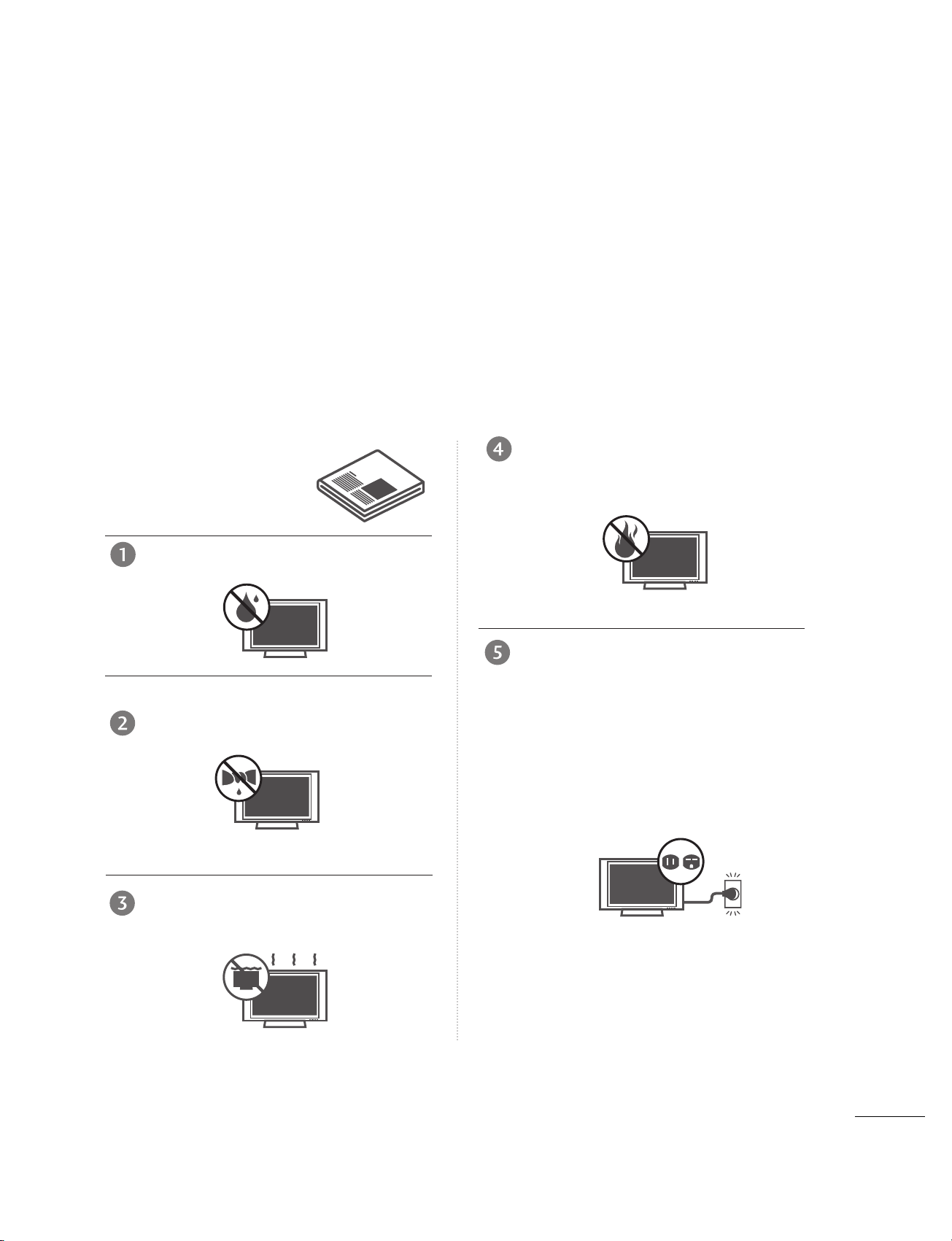
Do not use this apparatus near water.
Clean only with dry cloth.
Do not block any ventilation openings. Install in
accordance with the manufacturer’s instructions.
Do not install near any heat sources such as
radiators, heat registers, stoves, or other apparatus
(including amplifiers)that produce heat.
Do not defeat the safety purpose of the
polarized or grounding-type plug. A polarized
plug has two blades with one wider than the
other. A grounding type plug has two blades
and a third grounding prong, The wide blade
or the third prong are provided for your safety.
If the provided plug does not fit into your
outlet, consult an electrician for replacement
of the obsolete outlet.
Important safety instructions shall be provided with each apparatus. This information shall be given in a separate booklet or sheet, or be located before any operating instructions in an instruction for installation for
use and supplied with the apparatus.
This information shall be given in a language acceptable to the country where the apparatus is intended to
be used.
The important safety instructions shall be entitled “Important Safety Instructions”. The following safety
instructions shall be included where applicable, and, when used, shall be verbatim as follows. Additional safety information may be included by adding statements after the end of the following safety instruction list. At
the manufacturer’s option, a picture or drawing that illustrates the intent of a specific safety instruction may
be placed immediately adjacent to that safety instruction :
Owner Manual
Page 4
2
IMPORTANT SAFETY INSTRUCTIONS
WARNING
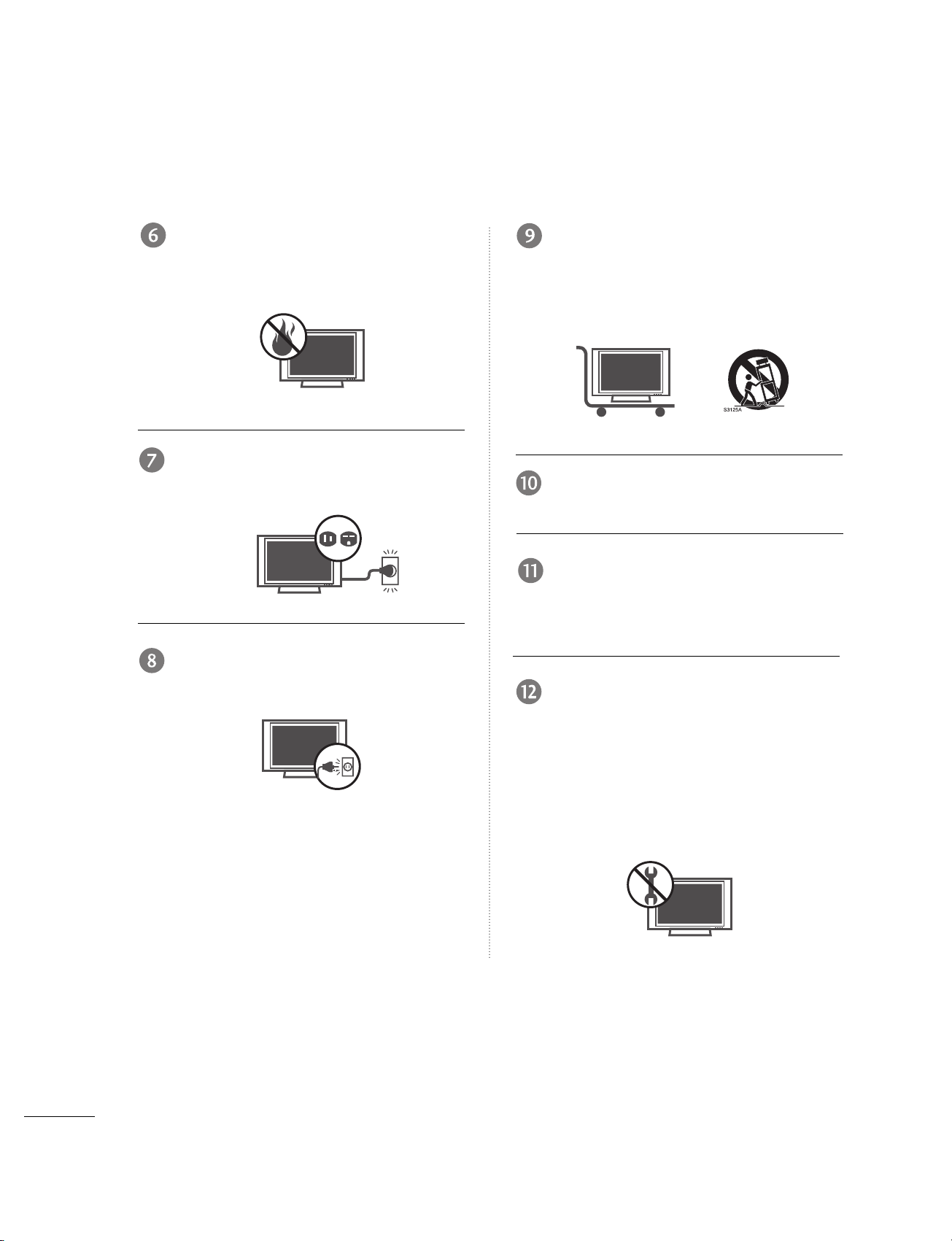
Protect the power cord from being walked on
or pinched particularly at plugs, convenience
receptacles, and the point where they exit
from the apparatus.
Only use attachments/accessories specified
by the manufacturer.
Unplug this apparatus when unused for long
periods of time.
Use only with the cart, stand, tripod, bracket,
or table specified by the manufacturer, or sold
with the apparatus. When a cart is used, use
caution when moving the cart/apparatus
combination to avoid injury from tip-over.
Never touch this apparatus or antenna during
a thunder or lighting storm.
Do not allow a impact shock or any objects to
fall into the product, and do not drop onto the
screen with something. (You may be injured or
the product can be damaged.)
Refer all servicing to qualified service personnel.
Servicing is required when the apparatus has
been damaged in any way, such as power-supply
cord or plug is damaged, liquid has been
spilled or objects have fallen into the apparatus,
the apparatus has exposed to rain or moisture,
does not operate normally, or has been
dropped.
Owner Manual
Page 5
3
WARNING
CAUTION concerning the Power Cord :
Most appliances recommend they be placed
upon a dedicated circuit; that is, a single outlet
circuit which powers only that appliance and
has no additional outlets or branch circuits.
Check the specification page of this owner's
manual to be certain.
Do not overload wall outlets. Overloaded wall
outlets, loose or damaged wall outlets, extension
cords, frayed power cords, or damaged or
cracked wire insulation are dangerous. Any of
these conditions could result in electric shock
or fire. Periodically examine the cord of your
appliance, and if its appearance indicates
damage or deterioration, unplug it, discontinue
use of the appliance, and have the cord
replaced with an exact replacement part by
an authorized servicer. Protect the power cord
from physical or mechanical abuse, such as
being twisted, kinked, pinched, closed in a
door, or walked upon. Pay particular attention
to plugs, wall outlets, and the point where
the cord exits the appliance.
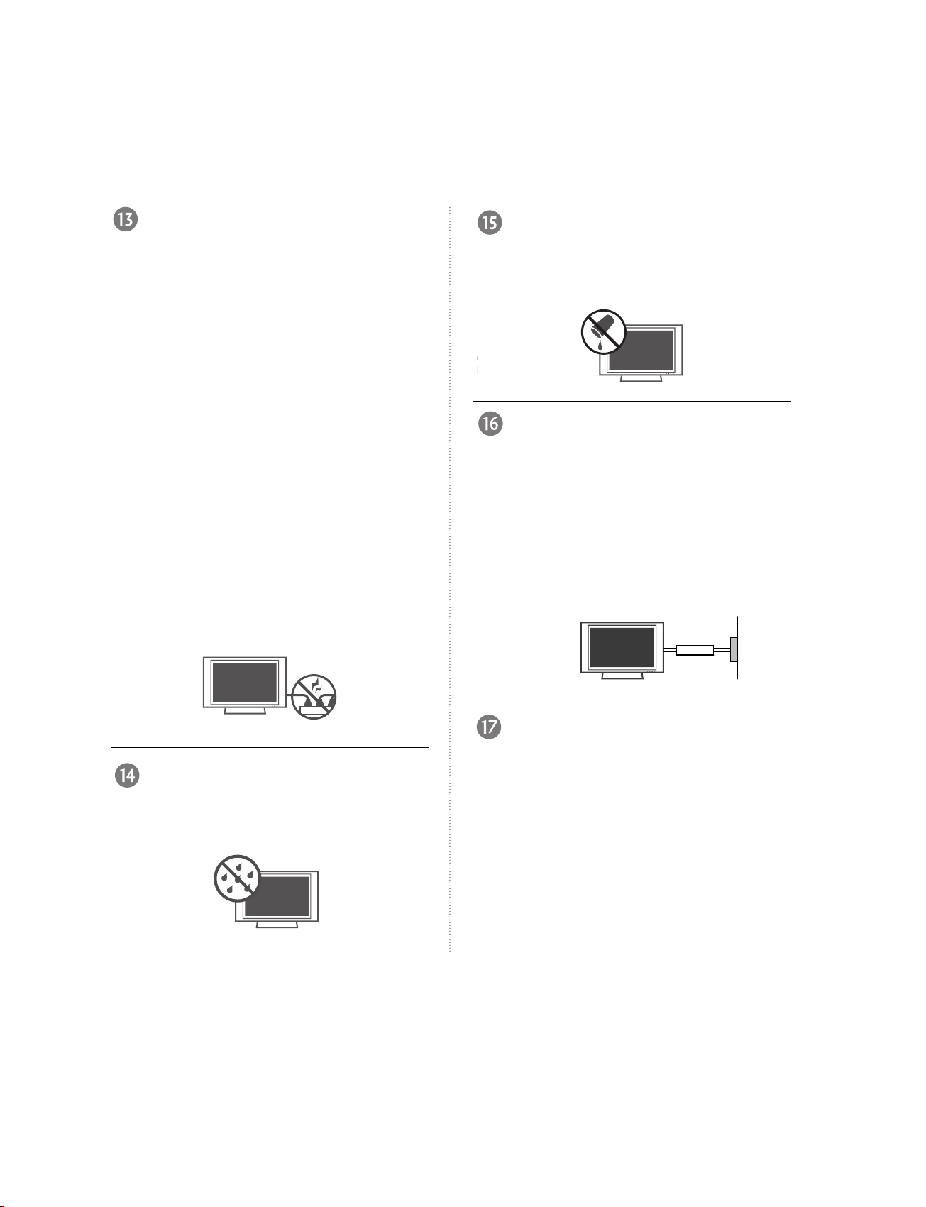
Outdoor Use Marking :
WARNING - To Reduce The Risk Of Fire Or
Electric Shock, Do Not Expose This Appliance
To Rain Or Moisture
Wet Location Marking : Apparatus shall not
be exposed to dripping or splashing and no
objects filled with liquids, such as vases, shall
be placed on or over apparatus.
GROUNDING
Ensure that you connect the earth ground
wire to prevent possible electric shock. If
grounding methods are not possible, have a
qualified electrician install a separate circuit
breaker.
Do not try to ground the unit by connecting
it to telephone wires, lightening rods, or gas
pipes.
DISCONNECTING DEVICE FROM MAINS
Main plug is the disconnecting device. The
plug must remain readily operable.
Owner Manual
Power Supply
Short-circuit Breaker
Owner Manual
Owner Manual
Page 6

4
CONTENTS
WARNING . . . . . . . . . . . . . . . . . . . . . . . . . . . . . . . . . . . . . . . . . . . . . . . . . .1
FEATURES OF THIS TV
. . . . . . . . . . . . . . . . . . . . . . . . . . . . .6
PREPARATION
Accessories . . . . . . . . . . . . . . . . . . . . . . . . . . . . . . 7
Front Panel Controls . . . . . . . . . . . . . . . . . . . . . . 8
Back Panel Information . . . . . . . . . . . . . . . . . . . 10
Back Cover for Wire Arrangement . . . . . . . . . . . 12
Attaching the TV to a Wall . . . . . . . . . . . . . . . . . 14
Stand Installation . . . . . . . . . . . . . . . . . . . . . . . . .15
Antenna or Cable Connection . . . . . . . . . . . . . . 18
EXTERNAL EQUIPMENT SETUP
HD Receiver Setup . . . . . . . . . . . . . . . . . . . . . . . . . . . . . . . . . . . . . . . . . 19
DVD Setup
. . . . . . . . . . . . . . . . . . . . . . . . . . . . . . . . . . . . . . . . . . . . . . . . . . . . . 22
VCR Setup
. . . . . . . . . . . . . . . . . . . . . . . . . . . . . . . . . . . . . . . . . . . . . . . . . . . . . . 24
Other A/V Source Setup . . . . . . . . . . . . . . . . . . . . . . . . . . . . . . . . . 26
PC Setup
. . . . . . . . . . . . . . . . . . . . . . . . . . . . . . . . . . . . . . . . . . . . . . . . . . . . . . . . 27
AV Out Setup . . . . . . . . . . . . . . . . . . . . . . . . . . . . . . . . . . . . . . . . . . . . . . . . . 33
External Stereo
. . . . . . . . . . . . . . . . . . . . . . . . . . . . . . . . . . . . . . . . . . . . . . . . 33
WATCHING TV / SETUP CONTROL
Remote Control Functions . . . . . . . . . . . . . . . . . .34
Turning on the TV . . . . . . . . . . . . . . . . . . . . . . . . 36
- Volume Adjustment . . . . . . . . . . . . . . . . . . . 36
- Channel Adjustment . . . . . . . . . . . . . . . . . . 36
On Screen Menus Selection and Adjustment . . 37
Auto tuning: Channel Search . . . . . . . . . . . . . . 38
Manual tuning: Adding/Deleting Channels . . . . . 39
Fine tuning Adjustment . . . . . . . . . . . . . . . . . . .40
Favorite Channels Setup
. . . . . . . . . . . . . . . . . .41
SIMPLINK . . . . . . . . . . . . . . . . . . . . . . . . . . . . . . 42
PICTURE CONTROL
PIP/Double Window . . . . . . . . . . . . . . . . . . . . . . .45
-
Watching PIP/Double Window . . . . . . . . . 45
-
TV Program Selection for PIP
. . . . . . . . . . . 45
-
Selecting an Input Signal Source for the
PIP/
Double Window
. . . . . . . . . . . . . . . . . .46
-
Sub Picture Size Adjustment (PIP mode only)
46
-
Moving the Sub Picture (PIP mode only)
. .46
Picture Mode Control . . . . . . . . . . . . . . . . . . . . . 47
Manual Picture Control (Picture mode-User option) . . 48
Color Temperature Control . . . . . . . . . . . . . . . .49
Manual Color Temperature Control (
User option)50
XD . . . . . . . . . . . . . . . . . . . . . . . . . . . . . . . . . . . . 51
Advanced - Cinema Mode Setup . . . . . . . . . . . . 52
Advanced - Black Level . . . . . . . . . . . . . . . . . . . . 53
Aspect Ratio Control . . . . . . . . . . . . . . . . . . . . . 54
Picture Reset . . . . . . . . . . . . . . . . . . . . . . . . . . . . 55
XD Demo . . . . . . . . . . . . . . . . . . . . . . . . . . . . . . 56
AUDIO CONTROL
Sound Mode Control . . . . . . . . . . . . . . . . . . . . . 57
Sound Control Adjustment (User option) . . . . . 58
Auto Volume Leveler . . . . . . . . . . . . . . . . . . . . . . . . . 59
Balance Adjustment . . . . . . . . . . . . . . . . . . . . . . .60
TV Speakers On/Off Setup . . . . . . . . . . . . . . . . 61
Stereo/SAP Broadcast Setup . . . . . . . . . . . . . . . 62
Page 7

5
TIME SETTING
Clock Setup . . . . . . . . . . . . . . . . . . . . . . . . . . . . . 63
On/Off Time Setup . . . . . . . . . . . . . . . . . . . . . . .64
Sleep Time . . . . . . . . . . . . . . . . . . . . . . . . . . . . . .65
Auto Sleep . . . . . . . . . . . . . . . . . . . . . . . . . . . . . . 66
OPTION CONTROL
On Screen Menus Language Selection
. . . . . . . . .67
Key Lock . . . . . . . . . . . . . . . . . . . . . . . . . . . . . . .68
Closed Captions . . . . . . . . . . . . . . . . . . . . . . . . 69
ISM (Image Sticking Minimization) Method . . .70
Low Power . . . . . . . . . . . . . . . . . . . . . . . . . . . . . . . . . . . . . . . . . . . . . . . . . . .71
APPENDIX
Troubleshooting Checklist
. . . . . . . . . . . . . . . . . . . . . . . . . . . . . . . .
72
Maintenance
. . . . . . . . . . . . . . . . . . . . . . . . . . . . . . . . . . . . . . . . . . . . . . . . . .
74
Product Specifications
. . . . . . . . . . . . . . . . . . . . . . . . . . . . . . . . . . . . .
75
Programming the Remote Control
. . . . . . . . . . . . . . . . . . . . . .
77
Programming Codes
. . . . . . . . . . . . . . . . . . . . . . . . . . . . . . . . . . . . . . . .
77
Page 8

6
FEATURES OF THIS TV
What is a Plasma TV ?
Using plasma is the best way to achieve flat panel
displays with excellent image quality and large
screen sizes that are easily viewable. The Plasma TV
can be thought of as a descendant of the neon
lamp and or a series of fluorescent lamps.
How does it work?
Plasma TV is an array of cells, known as pixels, which
are comprised of three sub-pixels, corresponding to
the colors red, green, and blue. Gas in a plasma
state is used to react with phosphors in each subpixel to produce colored light (red, green, or blue).
These phosphors are the same types used in
Cathode Ray Tube (CRT) devices such as televisions
and common computer monitors.
Plasma TV offers a rich, dynamic display because
each sub-pixel is individually controlled by advanced
electronics to produce over 16 million different colors.
This means that you get perfect images that are
easily viewable in a display that is fewer than five
inches thick.
160° - Wide angle range of vision
Your flat panel plasma screen offers an exceptionally
broad viewing angle of over 160 degrees. This
means that the display is clear and visible to viewers
anywhere in the room.
Wide Screen
The wide screen offers a theater-like experience in
your own home.
Multimedia
Connect your plasma display to a PC and use it for
conferencing, games, and Internet browsing. The
Picture-in-Picture feature allows you to view your PC
and video images simultaneously.
Versatile
The light weight and thin size makes it easy to
install your plasma display in a variety of locations
where conventional TVs do not fit.
The Plasma TV Manufacturing Process: a few
minute colored dots may be present on the
Plasma TV screen
The Plasma TV is composed of 0.9 to 2.2 million
cells. A few cell defects will normally occur in the
Plasma TV manufacturing process. Several tiny,
minute colored dots visible on the screen should be
acceptable. This also occurs in other Plasma TV
manufacturers' products. The tiny dots appearing
does not mean that this Plasma TV is defective.
Thus a few cell defects are not sufficient cause for
the Plasma TV to be exchanged or returned. Our
production technology minimizes these cell defects
during the manufacture and operation of this product.
FOR LCD TV
If the TV feels cold to the touch, there may be a
small “flicker” when it is turned on. This is normal,
there is nothing wrong with TV.
Some minute dot defects may be visible on the
screen, appearing as tiny red, green, or blue spots.
However, they have no adverse effect on the monitor's
performance.
Avoid touching the LCD screen or holding your finger(s)
against it for long periods of time. Doing so may produce
some temporary distortion effects on the screen.
OOnn DDiissppoossaall
a. The fluorescent lamp used in this product contains
a small amount of mercury.
b. Do not dispose of this product with general
household waste.
c. Disposal of this product must be carried out in
accordance to the regulations of your local
authority.
Page 9
7
PREPARATION
PREPARATION
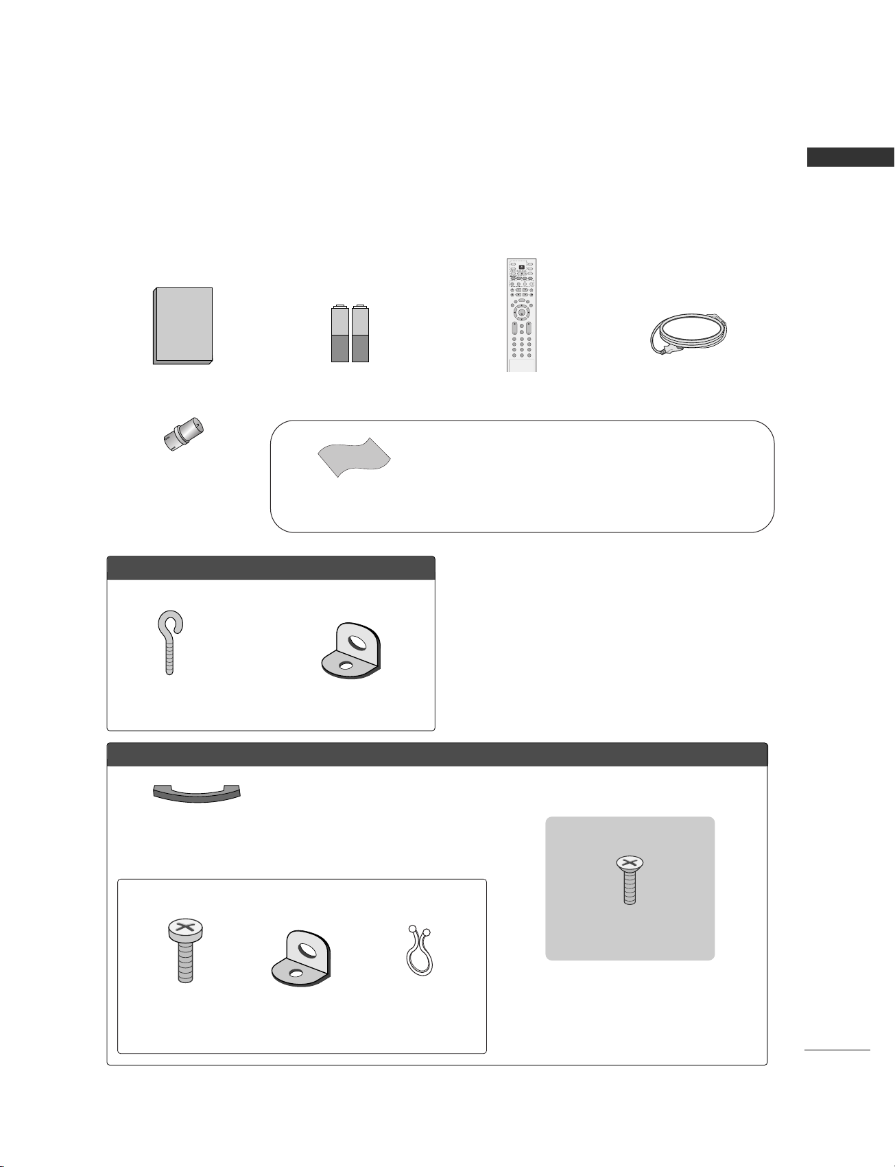
ACCESSORIES
Ensure that the following accessories are included with your product. If an accessory is missing,
please contact the dealer where you purchased the product.
FFoorr LLCCDD TTVV mmooddeellss
2-eye-bolts 2-Wall brackets
FFoorr PPllaassmmaa TTVV mmooddeellss
Cable Management
2- TV Bracket Bolts 2- TV Brackets,
2- Wall Brackets
Twister Holder
Arrange the wires with
the twister holder.
4-Bolts for stand assembly
(Refer to p.15)
2266 ””,, 33 22””,, 3377”” oonnllyy
Polishing cloth
Polish the screen with the cloth.
* Slightly wipe stained spot on the exterior only with the cleansing
cloths for the product exterior if there is stain or fingerprint on
surface of the exterior.
* Do not wipe roughly when removing stain. Please be cautious
of that excessive power may cause scratch or discoloration.
* This feature is not available for all models.
* This feature is not available for all models.
RF Adapter
(Some models)
You must connect it to the antenna
wire after fixing in Antenna Input.
This adapter is only supplied in
Argentina.
Owner's Manual
1.5V 1.5V
Owner’s Manual Batteries
(Some models)
ENTER
INPUT MODE
TVTV
DVD
RATIO
EXIT
VOLCH
PIP
CAPTION
MEMORY/ERASE
REVIEW
MTS
MENU
VCR
PIP CH- PIP CH+
PIP INPUT
POWER
123
456
789
0
FCR
SLEEP
SIMPLINK
INPUT
SIZE
POSITION
MUTE
Remote Control Power Cord
Page 10
8
PREPARATION
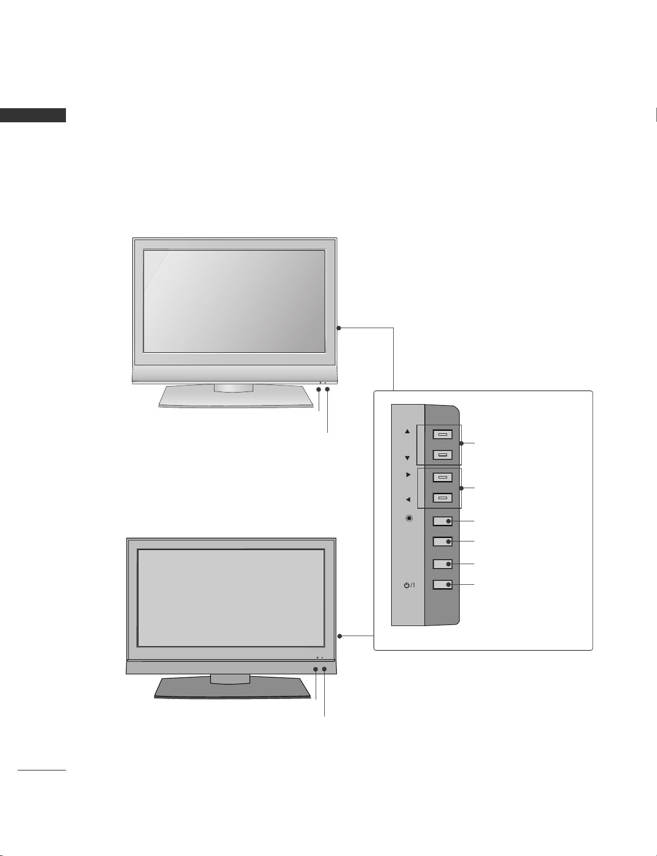
FRONT PANEL CONTROLS
PREPARATION
■
This is a simplified representation of the front panel. Here shown may be somewhat different from your TV.
■
If your product has a protection tape attached, remove the tape and then wipe the product with a cloth.
(If a polishing cloth is included with your product, use it.)
CH
VOL
ENTER
MENU
INPUT
Remote Control Sensor
Power Standby Indicator
Illuminates red in standby mode.
When the TV is turned on, the indicator blinks green and
then illuminates green before the picture is displayed.
CHANNEL Buttons
VOLUME Buttons
ENTER Button
MENU Button
INPUT Button
ON/OFF Button
<26LC4R*/32/37/42LC4R>
CH
VOL
ENTER
MENU
INPUT
<26LC7R>
Remote Control Sensor
Power Standby Indicator
Illuminates red in standby mode.
When the TV is turned on, the indicator blinks green and then illuminates
green before the picture is displayed.
Page 11

9
PREPARATION
Power/Standby Indicator
Illuminates red in standby mode.
Illuminates green when the set is
switched on.
Remote Control Sensor
CH
VOL
MENU
INPUT
ENTER
Power Standby Indicator
Illuminates red in standby mode.
When the TV is turned on, the indicator
blinks green and then illuminates green
before the picture is displayed.
Remote Control Sensor
POWER
Button
INPUT
Button
MENU
Button
ENTER
Button
VOLUME
(
FF,GG
)Buttons
CHANNEL
(
EE,DD
)Buttons
<42PC7R*>
<42PC5R*/50PC5R>
CH
VOL
ENTER
MENU
INPUT
POWER
Button
INPUT
Button
MENU
Button
ENTER
Button
VOLUME
(
FF,GG
)Buttons
CHANNEL
(
EE,DD
)Buttons
Page 12
AV IN 2
L/MONO
R
AUDIOAUDIO
VIDEOVIDEO
S-VIDEO
10
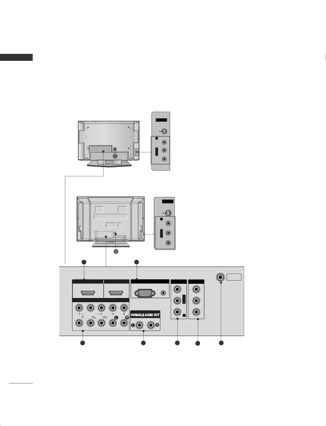
BACK PANEL INFORMATION
PREPARATION
PREPARATION
Back Connection Panel
R
S-VIDEO Input
Provides better picture quality than the video input.
AUDIO Input
VIDEO Input
Connects the video signal from a video device.
8
AV IN 2
HDMI IN HDMI/DVI IN
1
1
2
2
RGB IN
COMPONENT IN
AV IN 1 AV OUT
L/MONO
R
AUDIO
VIDEO
21
43 5 7
6
<42PC7R*>
<42PC5R*/50PC5R>
AV IN 2
L/L/MONO
R
AUDIOAUDIO
VIDEOVIDEO
S-VIDEO
S-VIDEO Input
Provides better picture quality than the video input.
AUDIO Input
VIDEO Input
Connects the video signal from a video device.
8
COMPONENT IN
VIDEO
AUDIO
RGB
(PC)
AUDIO
(RGB/DVI)
VIDEO
AUDIO
ANTENNA
IN
Page 13
11
PREPARATION
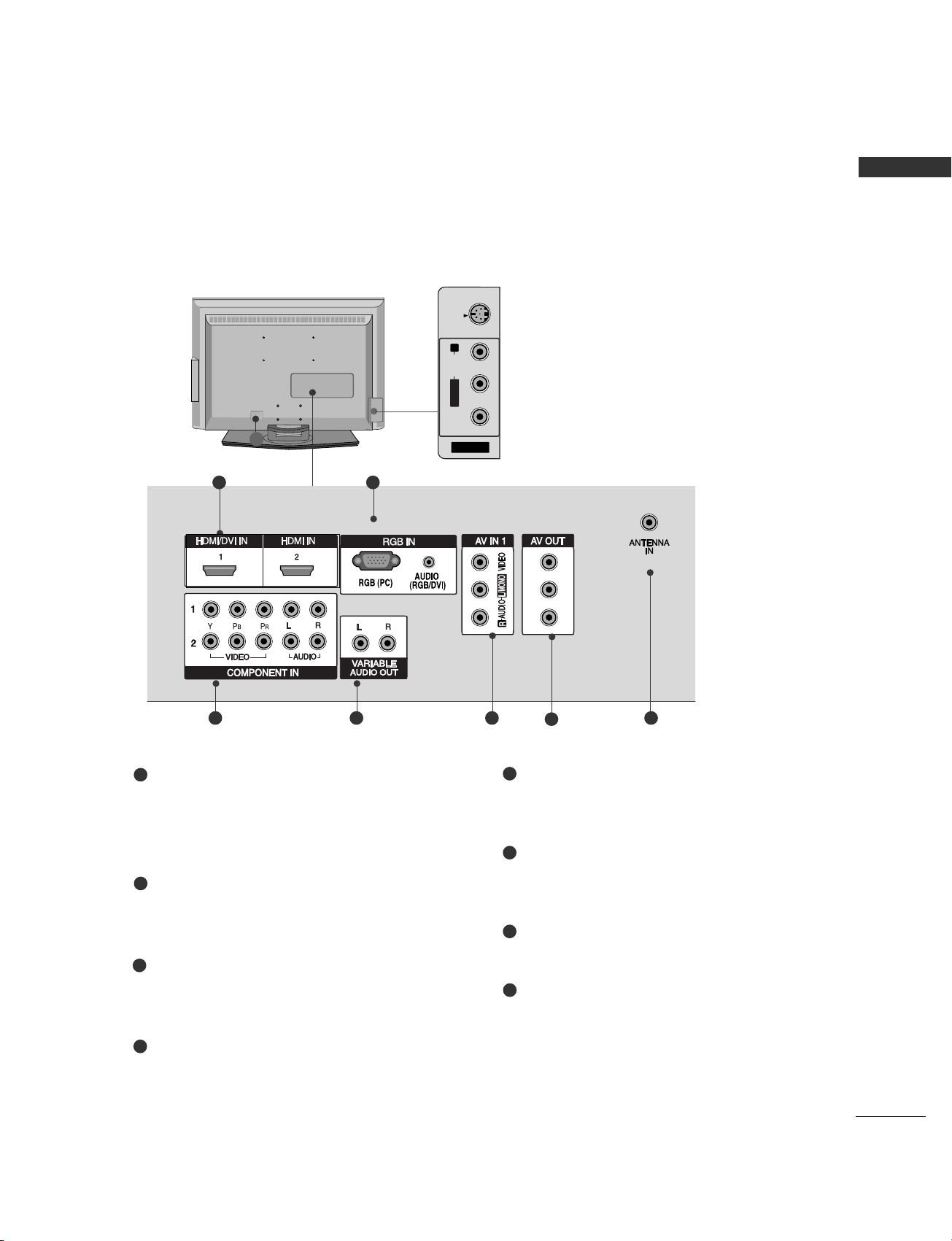
<26LC4R*/26LC7R/32/37/42LC4R>
AV IN 2
L/ MONO
R
AUDIO
VIDEO
S-VIDEO
S-VIDEO Input
Provides better picture quality than the
video input.
AUDIO Input
VIDEO Input
Connects the video signal from a video
device.
8
HDMI/DVI, HDMI Input
Connect a HDMI signal to HDMI IN.
Or DVI(VIDEO)signal to HDMI/DVI port with DVI
to HDMI cable.
RGB/Audio Input
Connect the monitor output from a PC, DTV(only
Audio) to the appropriate input port.
Component Input 1/2
Connect a component video/audio device to
these jacks.
Variable Audio Output
Connect an external amplifier or add a subwoofer
to your surround sound system.
AV IN 1
Connect audio/video output from an external
device to these jacks.
AV OUT
Connect second TV or monitor to the AV OUT
socket on the set.
Antenna In
Connect over-the-air signals to this jack.
Power Cord Socket
This TV operates on an AC power. The voltage is
indicated on the Specifications page. Never
attempt to operate the TV on DC power.
1
2
3
4
5
6
7
8
21
43 5 7
6
This is the back panel of model 26/32LC4R.
Page 14
12
BACK COVER FOR WIRE ARRANGEMENT
PREPARATION
PREPARATION
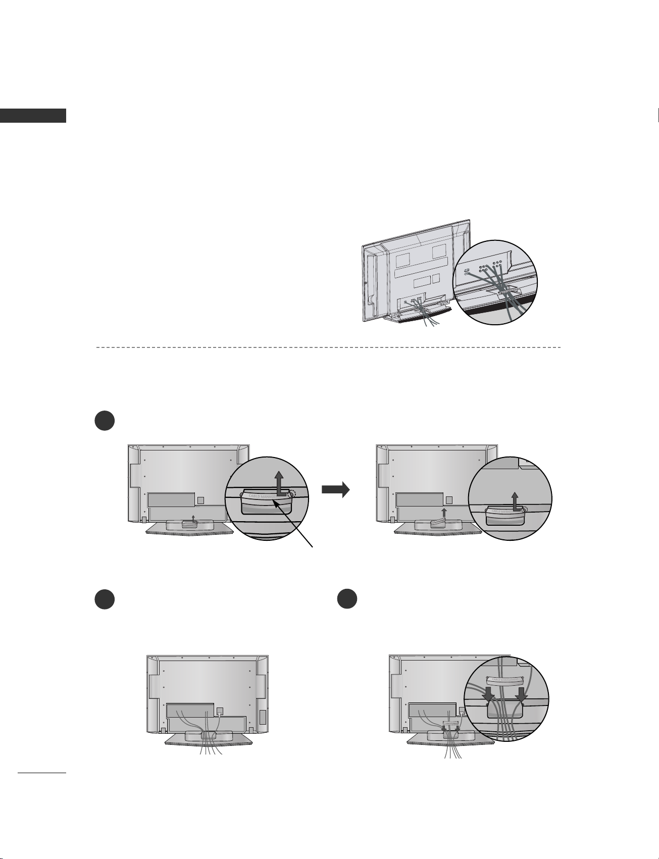
Plasma TV models
■
These models have two cable arrangement methods according to the stand type.
Connect the cables as necessary.
To connect an additional equipment, see the
EExxtteerrnnaa ll eeqquuiippmmeenntt CCoonnnneeccttiioonnss
section.
Reinstall the
CCAABBLLEE MMAANNAAGGEEMMEENN TT
as shown.
2
1
3
CABLE MANAGEMENT
Hold the
CCAABBLLEE MMAANNAAGGEEMMEENNTT
with hands and push it as shown.
Stand type 1
Stand type 2
Arrange the cables as shown picture.
Page 15
13
PREPARATION
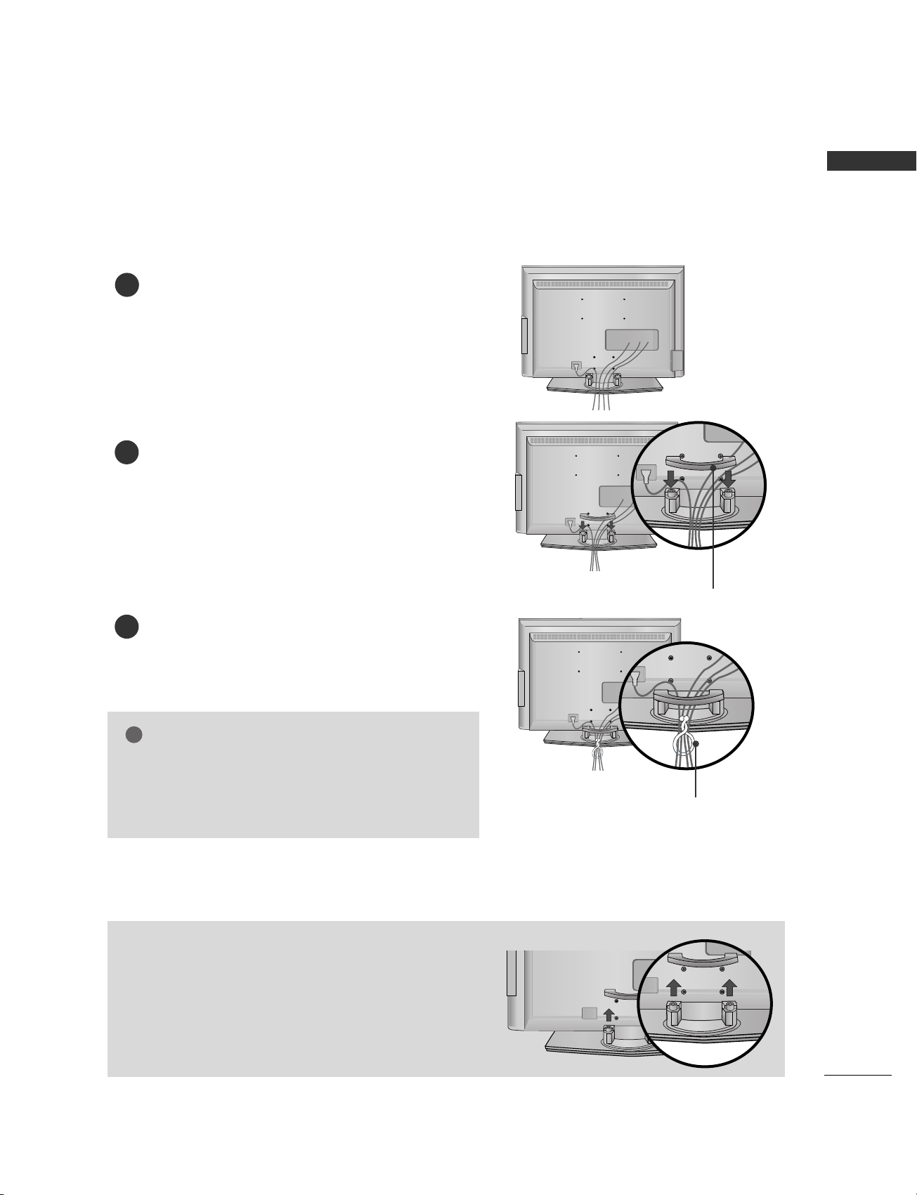
<26LC4R*/26LC7R/32/37/42LC4R>
Connect the cables as necessary.
To connect an additional equipment, see the External
equipment Connections section.
Install the CABLE MANAGEMENT as shown.
How to remove the CABLE MANAGEMENT
GG
Hold the CABLE MANAGEMENT with both hands and
pull it backward.
CABLE MANAGEMENT
TWISTER HOLDER
GG
Do not hold the CABLE MANAGEMENT when moving
the product.
- If the product is dropped, you may be injured or the
product may be broken.
NOTE
!
1
2
Bundle the cables using the supplied twister holder.
(This feature is not available for all models.)
3
Page 16
14
PREPARATION
PREPARATION
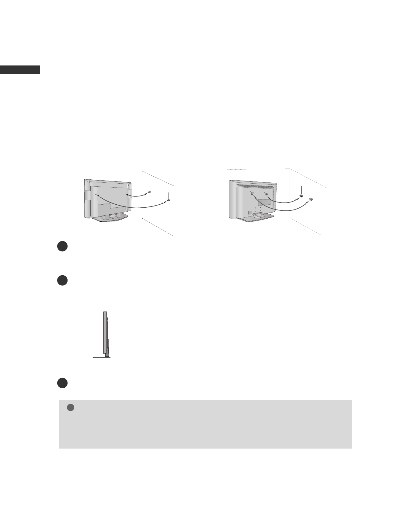
ATTACHING THE TV TO A WALL
Plasma TV Model LCD TV Model
■
Set it up close to the wall so the set doesn’t fall over when it is pushed backwards.
■
The instructions shown below is a safer way to set up the set, which is to fix it on the wall so the set doesn’t
fall over when it is pulled in the forward direction. It will prevent the set from falling for-ward and hurting
people. It will also prevent the set from damage caused by fall. Please make sure that children don’t climb
on or hang from the set.
Use a sturdy rope (not provided as parts of the set, must purchase separately) to tie the set. It is safer to tie
the rope so it becomes horizontal between the wall and the set.
Use the eye-bolts or set brackets/bolts to fix the set to the wall as shown in the picture.
(If your set has the bolts in the eye-bolts position before inserting the eye-bolts, loosen the bolts.)
* Insert the eye-bolts or set brackets/bolts and tighten them securely in the upper holes.
Secure the wall brackets with the bolts (not provided as parts of the set, must purchase separately) on the
wall. Match the height of the bracket that is mounted on the wall.
NOTE
!
GG
When moving the set to another place undo the ropes first.
GG
Use a set holder or a cabinet that is big and strong enough for the size and weight of the set.
GG
To use the set safely make sure that the height of the bracket that is mounted on the wall is same as that
of the set.
1
3
2
2
1
2
3
1
* This feature is not available for all models.
Page 17

15
PREPARATION
STAND INSTALLATION (Only 26/32/37 inch LCD TV models)
Carefully place the product screen side down on
a cushioned surface that will protect product and
screen from damage.
Assemble the product stand with the product as
shown.
Install the 4 bolts securely, in the back of the
product in the holes provided.
1
2
3
Page 18
16
PREPARATION
PREPARATION
■
The TV can be installed in various ways such as on a wall, or on a desktop etc.
■
The TV is designed to be mounted horizontally.
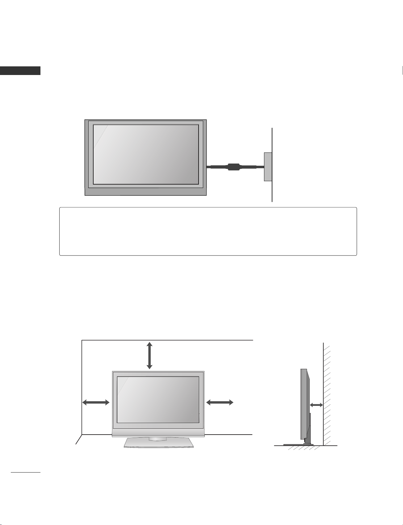
DESKTOP PEDESTAL INSTALLATION
For proper ventilation, allow a clearance of 4inches on each side from the wall.
4 inches
4 inches
4 inches
4 inches
Power Supply
Short-circuit Breaker
GROUNDING
Ensure that you connect the earth ground wire to prevent possible electric shock. If grounding methods
are not possible, have a qualified electrician install a separate circuit breaker.
Do not try to ground the unit by connecting it to telephone wires, lightening rods, or gas pipes.
Page 19

17
PREPARATION
WALL MOUNT: HORIZONTAL INSTALLATION
For proper ventilation, allow a clearance of 4" on each side and from the wall. Detailed installation instructions
are available from your dealer, see the optional Tilt Wall Mounting Bracket Installation and Setup Guide.
4 inches
4 inches
4 inches
4 inches
4 inches
<Only 42PC7R*>
Remove two screws of the backside of the set before installing the
wall mounting bracket.
Page 20

18
PREPARATION
ANTENNA OR CABLE CONNECTION
PREPARATION
Wall Antenna Socket or Outdoor Antenna without a Cable Box Connections.
For optimum picture quality, adjust antenna direction if needed.
ANTENNAANTENNA
ININ
Multi-family Dwellings/Apartments
(Connect to wall antenna socket)
Single-family Dwellings /Houses
(Connect to wall jack for outdoor antenna)
Outdoor
Antenna
(VHF, UHF)
Wall
Antenna
Socket
RF Coaxial Wire (75 ohm)
Bronze Wire
Be careful not to bend the bronze
wire when connecting the antenna.
The TV will let you know when the analog and cable scans are complete.
NOTE
!
ANTENNA
IN
ANTENNAANTENNA
ININ
Antenna
UHF
Signal
Amplifier
VHF
■
To improve the picture quality in a poor signal area, please purchase a signal amplifier and install properly.
■
If the antenna needs to be split for two TV’s, install a 2-Way Signal Splitter.
■
If the antenna is not installed properly, contact your dealer for assistance.
Page 21
EXTERNAL EQUIPMENT SETUP
19
EXTERNAL EQUIPMENT SETUP
HD RECEIVER SETUP
AUDIO
(RGB/DVI)
RG
(PC
RGB
(PC)
1 2
VIDEOVIDEOVIDEO
AUDIOAUDIOAUDIO
11
22
HDMI/DVI IN HDMI IN
AUDIO
VARI A
Y L RPB PR
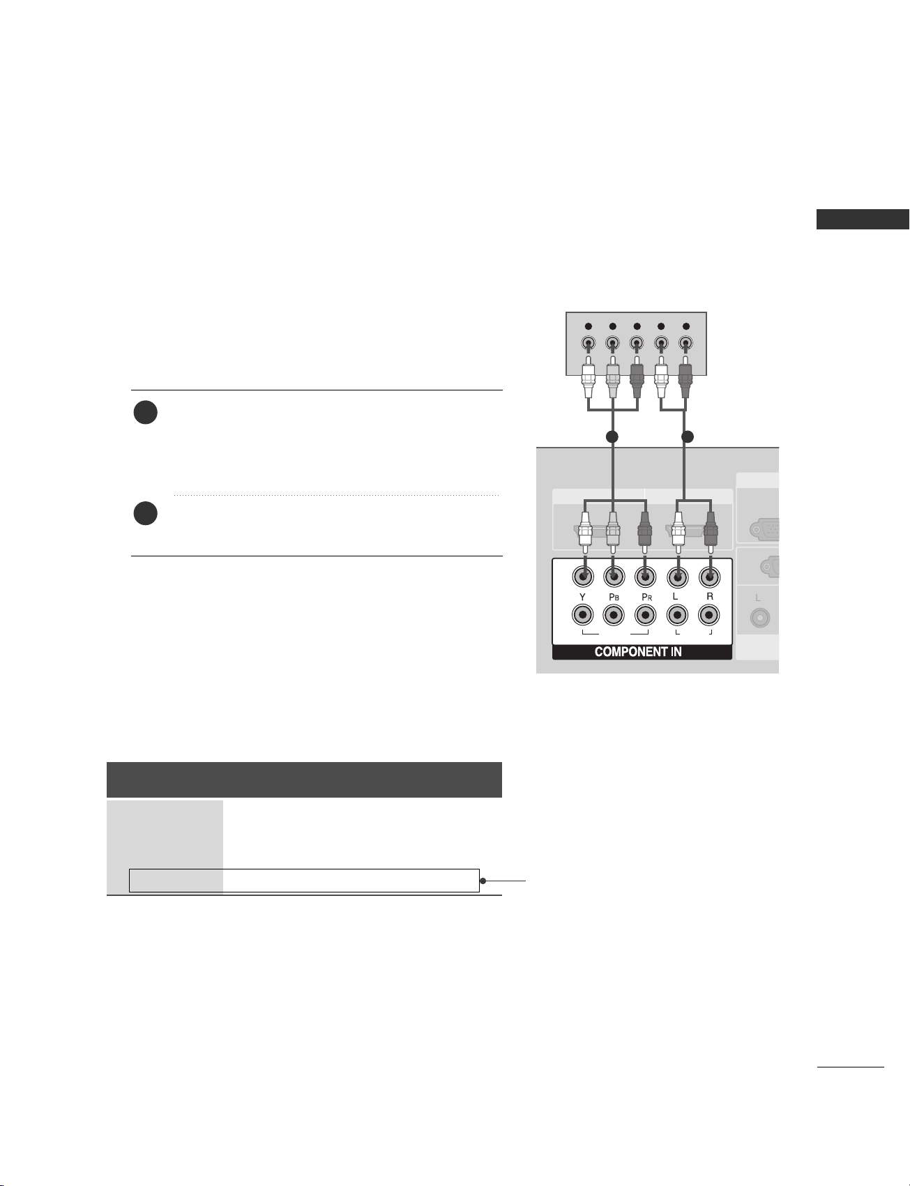
When connecting with a component cable
1. How to connect
Connect the video outputs (Y, PB, PR
)
of the digital set
top box to the
CCOOMMPPOONNEENNTT IINN VVIIDDEEOO 11
jacks
on the set. Match the jack colors
(Y = green, P
B = blue, and PR
= red).
Connect the audio output of the digital set-top box to
the
CCOOMMPPOONNEENNTT IINN AAUUDDIIOO 11
jacks on the set.
2
1
2. How to use
■
Turn on the digital set-top box.
(
Refer to the owner’s manual for the digital set-top box.
)
■
Select
CCoommppoonneenntt 11
input source with using the
IINNPPUUTT
button on the remote control.
■
If connected to
CCOOMMPPOONN EENNTT IINN 22
input, select
CCoommppoonneenntt 22
input source.
Signal
480i
480p/720p
1080i
10 8 0 p
Component 1/2
Yes
Yes
Yes
No
HDMI1/DVI,
HDMI2
No
Yes
Yes
Yes
1 2
(except VGA Models: VGA models support up to 1080i)
■
To prevent the equipment damage, never plug in any power cords until you have finished connecting all equipment.
■
This part of EXTERNAL EQUIPMENT SETUP mainly use pictures for the LCD TV models.
Page 22
EXTERNAL EQUIPMENT SETUP
20
EXTERNAL EQUIPMENT SETUP
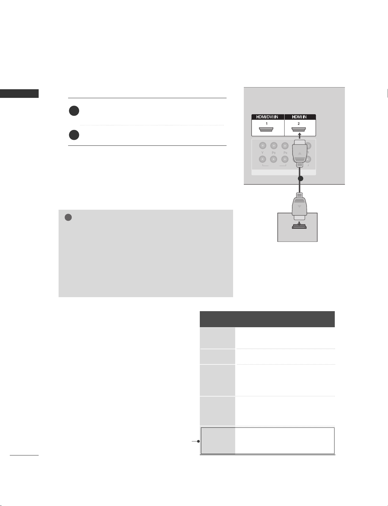
When connecting with a HDMI cable
Connect the digital set-top box to
HHDDMMII//DDVVII IINN 11
or
HHDDMMII IINN 22
jack on the set.
No separated audio connection is necessary.
1. How to connect
2. How to use
■
Turn on the digital set-top box.
(
Refer to the owner’s manual for the digital set-top box.
)
■
Select
HHDDMMII11
or
HHDDMMII22
input source with using the
IINNPPUUTT
button on the remote control.
2
1
1 2
VIDEOVIDEO
AUDIOAUDIO
1
2
HDMI/DVI IN HDMI IN
COMPONENT IN
HDMI-DTV OUTPUT
GG
TV can receive the video and audio signal simultaneously with
using a HDMI cable.
GG
If the digital set-top box supports Auto HDMI function, the
output resolution of the source device will be automatically
set to 1280x720p.
GG
If the digital set-top box player does not support Auto HDMI,
you need to set the output resolution appropriately.
To get the best picture quality, adjust the output resolution of
the source device to 1280x720p.
NOTE
!
1
Resolution
720x480
720x576
1280x720
1920x1080i
1920x1080p
Supported Display Resolution (HDMI-DTV mode)
Horizontal Vertical
Frequency(KHz) Frequency(Hz)
31.47 59.94
31.50 60.00
31.25 50.00
44.96 59.94
45.00 60.00
37.50 50.00
33.72 59.94
33.75 60.00
28.125 50.00
67. 432 59. 94
67.50 60.00
56.25 50.00
(except VGA Models:
VGA models support
up to 1080i)
Page 23

EXTERNAL EQUIPMENT SETUP
21
When connecting with a HDMI to DVI cable
AUDIO
(RGB/DVI)
AUDIO
(RGB/DVI)
RGB
(PC)
RGB
(PC)
1 2
VIDEO
AUDIO
1
2
L/MONO
R
AUDIO
VIDEO
HDMI/DVI IN HDMI IN
RGB IN
COMPONENT IN
RS-232C IN
(CONTROL & SERVICE)
AUDIO OUT
VARIABLE
AUDIO
(RGB/DVI)
RGB
(PC)
RGB
(PC)
RGB IN
1
HDMI/DVI IN
L R
DVI-DTV OUTPUT
1 2
Connect the DVI output of the digital set-top box to the
HHDDMMII//DDVVII IINN 11
jack on the set.
Connect the audio output of the digital set-top box to
the
AAUU DDIIOO((RRGGBB //DDVVII
))
jack on the set.
1. How to connect
2. How to use
■
Turn on the digital set-top box. (Refer to the owner’s manual
for the digital set-top box.
)
■
Select
HHDDMMII11
input source with using the
IINNPPUUTT
button
on the remote control.
2
1
Page 24
22
EXTERNAL EQUIPMENT SETUP
EXTERNAL EQUIPMENT SETUP
DVD SETUP
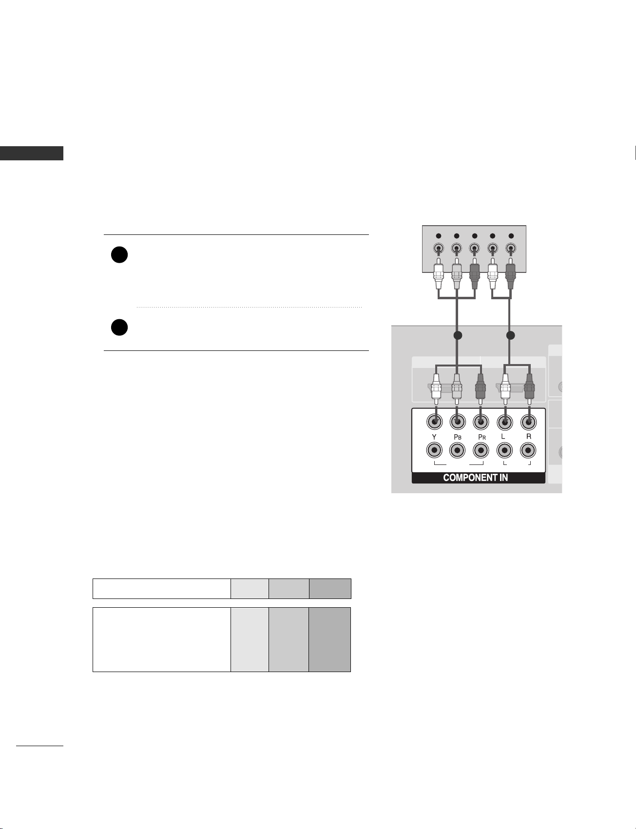
When connecting with a component cable
AUDIO
(RGB/DVI)
RGB
(PC)
1 2
VIDEOVIDEOVIDEO
AUDIOAUDIOAUDIO
11
22
HDMI/DVI IN HDMI IN
AU
V
Y L RPB PR
Component Input ports
To get better picture quality, connect a DVD player to the component input ports as shown below.
Component ports on the TV
YPB PR
Video output ports
on DVD player
Y
Y
Y
Y
P
B
B-Y
Cb
Pb
P
R
R-Y
Cr
Pr
Connect the video outputs (Y, PB, PR
)
of the DVD to the
CCOOMMPPOONN EENNTT IINN VVIIDDEEOO11
jacks on the set.
Match the jack colors
(
Y = green, P
B = blue, and PR = red
)
.
Connect the audio outputs of the DVD to the
CCOOMMPPOONN EENNTT IINN AAUUDDIIOO11
jacks on the set.
1. How to connect
2. How to use
■
Turn on the DVD player, insert a DVD.
■
Select
CCoommppoonneenntt 11
input source with using the
IINNPPUUTT
button on the remote control.
■
If connected to
CCOOMMPPOONN EENNTT IINN 22
input, select
CCoommppoonneenntt 22
input source.
■
Refer to the DVD player's manual for operating instructions.
2
1
1 2
Page 25

EXTERNAL EQUIPMENT SETUP
23
When connecting with an S-Video cable
S-VIDEO
AUDIO
(RGB/DVI)
RGB
(PC)
12
VIDEO
AUDIO
1
2
VIDEOVIDEO
AUDIOAUDIO
1
2
HDMI/DVI INHDMI/DVI IN HDMI INHDMI IN
1 2
HDMI-DVD OUTPUT
Connect the S-VIDEO output of the DVD to the
SS --VVIIDD EEOO
input on the set.
Connect the audio outputs of the DVD to the
AAUU DDIIOO
input jacks on the set.
1. How to connect
2. How to use
■
Turn on the DVD player, insert a DVD.
■
Select
AAVV22
input source with using the
IINNPPUUTT
button on
the remote control.
■
Refer to the DVD player's manual for operating instructions.
When connecting HDMI cable
Connect the HDMI output of the DVD to the
HHDDMMII//DDVVII IINN 11
or
HHDDMMII 22
jack on the set.
No separated audio connection is necessary.
1. How to connect
2. How to use
■
Select
HHDDMMII11 orHHDDMMII22
input source with using the
IINNPPUUTT
button on the remote control.
■
Refer to the DVD player's manual for operating instructions.
2
1
2
1
1
1
2
GG
TV can receive the video and audio signal simultaneously with
using a HDMI cable.
GG
If the DVD supports Auto HDMI function, the output resolution
of the source device will be automatically set to 1280x720p.
GG
If the DVD player does not support Auto HDMI, you need to set
the DVD output resolution appropriately.
To get the best picture quality, adjust the output resolution of the
source device to 1280x720p.
NOTE
!
S-VIDEO
S-VIDEOVIDEO
OUTPUT
SWITCH
L R
ANT IN
ANT OUT
Page 26

24
EXTERNAL EQUIPMENT SETUP
EXTERNAL EQUIPMENT SETUP
VCR SETUP
When connecting with an antenna
■
To avoid picture noise (interference), leave an adequate distance between the VCR and TV.
■
If the 4:3 picture format is used; the fixed images on the sides of the screen may remain visible on the
screen. This phenomenon is common to all manufactures and in consequence the manufactures warranty
does not cover the product bearing this phenomenon.
AUDIO
(RGB/DVI)
AUDIO
(RGB/DVI)
RGB
(PC)
RGB
(PC)
ANTENNA
IN
L/MONO
R
AUDIO
VIDEO
RGB IN
AUDIO OUT
VARIABLE
AV OUT
AV IN 1
L R
S-VIDEO VIDEO
OUTPUT
SWITCH
ANT IN
ANT OUT
Wall Jack
Antenna
Connect the RF antenna out socket of the VCR to the
AAnntteennnnaa
socket on the set.
Connect the antenna cable to the RF antenna in socket of the VCR.
1. How to connect
■
Set VCR output switch to 3 or 4 and then tune TV to the same channel number.
■
Insert a video tape into the VCR and press PLAY on the VCR. (Refer to the VCR owner’s manual.
)
2. How to use
2
1
2
1
Page 27

EXTERNAL EQUIPMENT SETUP
25
GG
Do not connect to both Video
and S-Video at the same time. In
the event that you connect both
Video and the S-Video cables,
only the S-Video will work.
CAUTION
When connecting with a RCA cable
GG
The picture quality is improved: compared to normal
composite (RCA cable) input.
NOTE
!
ANTENNA
IN
OL & SERVICE)
AV O UT
AUDIO
(RGB/DVI)
RGB
(PC)
ANTENNA
IN
L/MONO
R
AUDIO
VIDEO
L R
S-VIDEOVIDEO
OUTPUT
SWITCH
ANT IN
ANT OUT
S-VIDEO
Connect the
AAUU DDIIOO/VVII DD EEOO
jacks between TV and
VCR. Match the jack colors (Video = yellow, Audio Left
= white, and Audio Right = red)
1. How to connect
2. How to use
■
Insert a video tape into the VCR and press PLAY on the
VCR. (Refer to the VCR owner’s manual.
)
■
Select
AAVV11
input source with using the
IINNPPUUTT
button on
the remote control.
■
If connected to
AAVV IINN22
, select
AAVV22
input source.
When connecting with an S-Video cable
Connect the S-VIDEO output of the VCR to the
SS --VVIIDD EEOO
input on the set.
Connect the audio outputs of the VCR to the
AAUU DDIIOO
input jacks on the set.
1. How to connect
2. How to use
■
Insert a video tape into the VCR and press PLAY on the VCR.
(
Refer to the VCR owner’s manual.
)
■
Select
AAVV22
input source with using the
IINNPPUUTT
button on
the remote control.
1
2
1
GG
If you have a mono VCR, connect
the audio cable from the VCR
to the
AAUUDDIIOO LL// MMOONNOO
jack
of the set.
NOTE
!
1
1 2
L R
S-VIDEOVIDEO
OUTPUT
SWITCH
ANT IN
ANT OUT
S-VIDEO
Page 28

26
EXTERNAL EQUIPMENT SETUP
EXTERNAL EQUIPMENT SETUP
OTHER A/V SOURCE SETUP
Connect the
AAUUDDIIOO/VVIIDDEEOO
jacks
between TV and external equipment.
Match the jack colors
.
(
Video = yellow, Audio Left = white, and
Audio Right = red
)
1. How to connect
2. How to use
■
Select
AAVV22
input source with using the
IINNPPUUTT
button on the remote control.
■
If connected to
AAVV IINN11
input, select
AAVV11
input source.
■
Operate the corresponding external
equipment.
1
S-VIDEO
Camcorder
Video Game Set
1
S-VIDEO
VIDEO
L R
Page 29

PC SETUP
EXTERNAL EQUIPMENT SETUP
27
This TV provides Plug and Play capability, meaning that the PC adjusts automatically to the TV's settings.
When connecting with a D-sub 15 pin cable
GG
Check the image on your TV. There may be noise associated
with the resolution, vertical pattern, contrast or brightness
in PC mode. If noise is present, change the PC output to
another resolution, change the refresh rate to another
rate or adjust the brightness and contrast on the VIDEO
menu until the picture is clear. If the refresh rate of the
PC graphic card can not be changed, change the PC
graphic card or consult the manufacturer of the PC
graphic card.
NOTE
!
L/MONO
R
AUDIO
VIDEO
AUDIO OUT
VARIABLE
AV IN 1
AUDIO
(RGB/DVI)
RGB (PC)
RGB IN
RGB OUTPUT
AUDIO
Connect the RGB output of the PC to the
RR GGBB((PPCC
))
jack on the set.
Connect the PC audio output to the
AAUU DDIIOO
((
RRGGBB //DDVVII
))
jack on the set.
1. How to connect
2. How to use
■
Turn on the PC and the set.
■
Select
RRGGBB --PPCC
input source with using the
IINNPPUUTT
button
on the remote control.
2
1
1
2
Page 30

28
EXTERNAL EQUIPMENT SETUP
EXTERNAL EQUIPMENT SETUP
Resolution
640x350
720x400
640x480
848x480
852x480
800x600
1024x768
1280x768
1360x768
1366x768
Supported Display Resolution (RGB[PC] mode)
Horizontal Vertical
Frequency(KHz) Frequency(Hz)
31.468 70.09
31.469 70.08
31.469 59.94
31.5 60.00
31.5 60.00
37.879 60.31
48.363 60.00
47.776 59.87
47. 720 59. 799
47. 720 59. 799
NOTE
!
GG
It’s supported to 848x480, 852x480 in VGA
modes. (VGA Models)
GG
It’s supported to 1280x768, 1360x768,
1366x768 in XGA modes. (XGA Models)
NOTE
!
GG
To enjoy vivid picture and sound,connect a PC to
the set.
GG
Avoid keeping a fixed image on the set’s screen
for a long period of time. The fixed image may
become permanently imprinted on the screen;
use a screen saver when possible.
GG
Connect PC to the RGB (PC) port of the set;
change the resolution output of PC accordingly.
GG
There might be noise according to some resolu-
tion, vertical pattern, contrast or brightness in
PC mode. Change the PC mode into another
resolution or change the refresh rate into another
rateor adjust the brightness and contrast on the
menu until the picture is clean.If the refresh rate
of the PC graphic card can not be changed,
change the PC graphic card or consult it to the
manufacturer of the PC graphic card.
GG
The synchronization input waveform for
Horizontal and Vertical frequencies are separate.
GG
We recommend using 1366x768, 60Hz (LCD TV
models) / 852x480, 60Hz (42 inch WVGA
PLASMA TV models) / 1024x768, 60Hz (42
inch XGA PLASMA TV models) / 1360x768,
60Hz (50 inch PLASMA TV models) for the PC
mode, they provide the best picture quality.
GG
If the resolution of PC is over SXGA, there will
be no picture on the set.
GG
Connect the audio cable from the PC to the
Audio input on the set. (Audio cables are not
included with the set).
GG
When you use too long RGB-PC cable, there
might be a noise on the screen. We recommend
using under 5m of the cable. It provides the
best picture quality.
Page 31

EXTERNAL EQUIPMENT SETUP
29
SCREEN SETUP FOR PC MODE
Automatically adjusts picture position and minimizes image
shaking.
Although the image is still not correct, your set is functioning
properly but needs further adjustment.
AAuuttoo ccoonnffiigguurree
This function is for the automatic adjustment of the screen position,
clock, and phase. The displayed image will be unstable for a few
seconds while the auto configuration is in progress.
Auto Configure (RGB [PC] mode only)
ENTER
EXIT
VOL
CH
CAPTION
MEMORY/ERASE
REVIEW
MENU
123
456
FCR
MUTE
Press the
MMEENNUU
button and then use DDor
EE
button to select the
PPiiccttuurree
menu.
Press the
GG
button and then use DDor EEbutton to
select
SSccrree eenn
.
Press the GGbutton and then use DDor EEbutton to
select
AAuuttoo ccoonnffii gg..
.
Press the GGbutton to start
AAuuttoo ccoonnffii gg..
.
• When
AAuuttoo ccoonnffii gg..
has finished,
OOKK
will be
shown on screen.
• If the position of the image is still not correct, try
Auto adjustment again.
If picture needs to be adjusted more after Auto
adjustment in RGB (PC), you can adjust the
MMaannuuaall ccoonnffiigg..
.
Press the
EEXX II TT
button to return to TV viewing or
press the
MMEENNUU
button to return to the previous
menu.
1
2
3
4
5
6
1
3 4
Picture Mode
Color Temperature
XD
Advanced
Aspect Ratio
Picture Reset
Screen
XD Demo
Picture
Screen
Auto config.
Manual Config.
XGA Mode
Reset
To Set
Auto Config. G
2
Picture
Picture Mode
Color Temperature
XD
Advanced
Aspect Ratio
Picture Reset
Screen
XD Demo
To Set
Screen G
DE F G
MENU
DE F G
MENU
DE F G
MENU
Page 32

30
EXTERNAL EQUIPMENT SETUP
EXTERNAL EQUIPMENT SETUP
Adjustment for screen Phase, Clock, Position
If the picture isn’t clear after auto adjustment and especially
if characters are still trembling, adjust the picture phase
manually.
To correct the screen size, adjust Clock.
This function works in the following mode : RGB[PC],
COMPONENT (480i/480p/720p/1080i), HDMI
(480p/720p/1080i/1080p(except VGA Models)).
It’s not available to use Phase, Clock function in
COMPONENT (480i/480p/720p/1080i), HDMI
(480p/720p/1080i/1080p(except VGA Models)).
CCll oocckk
This function is to minimize any vertical bars or
stripes visible on the screen background. And the
horizontal screen size will also change.
PPhhaa ssee
This function allows you to remove any horizontal
noise and clear or sharpen the image of characters.
ENTER
EXIT
VOL
CH
CAPTION
MEMORY/ERASE
REVIEW
MENU
123
456
FCR
MUTE
Press the
MMEENNUU
button and then use DDor
EE
button to select the
PPiiccttuurree
menu.
Press the
GG
button and then use DDor EEbutton to
select
SSccrree eenn
.
Press the GGbutton and then use DDor EEbutton to
select
MMaannuuaall ccoonnffiigg..
.
Press the GGbutton and then use DDor EEbutton to
select
PPhhaassee,, CClloocckk ,, HH --ppoossii ttiioonn
or
VV--ppoossiittiioonn
.
Press the
FF
or GGbutton to make appropriate
adjustments.
Press the
EEXX II TT
button to return to TV viewing or
press the
MMEENNUU
button to return to the previous
menu.
1
2
3
4
5
6
1
3 4 5
Picture Mode
Colour Temperature
XD
Advanced
Aspect Ratio
Picture Reset
Screen
XD Demo
Picture
Screen
Auto Config.
Manual Config.
XGA Mode
Reset
Phase 50
Clock 0
H-Position 0
V-Position 0
Manual Config. G
2
Picture
Picture Mode
Colour Temperature
XD
Advanced
Aspect Ratio
Picture Reset
Screen
XD Demo
To Set
Screen G
DE F G
MENU
DE F G
MENU
DE F G
MENU
Page 33

EXTERNAL EQUIPMENT SETUP
31
To see a normal picture, match the resolution of RGB mode and
selection of VGA/XGA mode.
This function works in the following mode: RGB[PC] mode.
Selecting Wide VGA/XGA mode
Press the
MMEENNUU
button and then use DDor
EE
button to select the
PPiiccttuurree
menu.
Press the
GG
button and then useDDor EEbutton to
select
SSccrree eenn
.
Press theGGbutton and then useDDor EEbutton to
select
XX GG AA MMooddee
(or
VVGG AA MMooddee
).
Press the
GG
button and then useDDor EEbutton to
select the desired VGA/XGA resolution.
Press the
EEXX II TT
button to return to TV viewing or
press the
MMEENNUU
button to return to the previous
menu.
1
2
3
4
5
ENTER
EXIT
VOL
CH
CAPTION
MEMORY/ERASE
REVIEW
MENU
123
456
FCR
MUTE
1
3 4
Picture Mode
Color Temperature
XD
Advanced
Aspect Ratio
Picture Reset
Screen
XD Demo
Picture
Screen
Auto Config.
Manual Config.
VGA Mode
Reset
1024x768
1280x768
1360x768
1366x768
XGA Mode G
2
Picture
Picture Mode
Color Temperature
XD
Advanced
Aspect Ratio
Picture Reset
Screen
XD Demo
To Set
Screen G
DE F G
MENU
DE F G
MENU
DE F G
MENU
Page 34

32
EXTERNAL EQUIPMENT SETUP
EXTERNAL EQUIPMENT SETUP
This function operates in current mode.
To initialize the adjusted value.
Press the
MMEENNUU
button and then use
DD
or
EE
button to select the
PPiiccttuurree
menu.
Press the
GG
button and then useDDor EEbutton to
select
SSccrree eenn
.
Press the
GG
button and then useDDor EEbutton to
select
RR eesseett
.
• You can initialize Position, PIP size, PIP position.
Press the
GG
button.
1
2
3
4
Initializing
(Reset to original factory settings)
ENTER
EXIT
VOL
CH
CAPTION
MEMORY/ERASE
REVIEW
MENU
123
456
FCR
MUTE
1
3 4
Picture Mode
Colour Temperature
XD
Advanced
Aspect Ratio
Picture Reset
Screen
XD Demo
Picture
Screen
Auto Config.
Manual Config.
XGA Mode
Reset
To Set
Reset G
2
Picture
Picture Mode
Colour Temperature
XD
Advanced
Aspect Ratio
Picture Reset
Screen
XD Demo
To Set
Screen G
DE F G
MENU
DE F G
MENU
DE F G
MENU
Page 35

EXTERNAL EQUIPMENT SETUP
33
AV OUT SETUP
The TV has a special signal output capability which allows you to hook up the second TV or monitor.
AV OUTAV OUT
ANTENNA
IN
L R
S-VIDEOVIDEO
OUTPUT
SWITCH
ANT IN
ANT OUT
Connect the second TV or monitor to the TV’s
AAVV
OOUUTT
jacks.
See the Operating Manual of the second TV or monitor
for further details regarding that device’s input settings.
1. How to connect
GG
Component, RGB, HDMI input sources cannot be used for
AV out.
GG
We recommend to use the AV OUT jacks for VCR recording.
NOTE
!
2
1
1
AUDIO
(RGB/DVI)
RGB
(PC)
AUDIO
AUDIO OUTAUDIO OUT
VARIABLEVARIABLE
GG
When connecting with external audio equipments, such as
amplifiers or speakers, please turn the TV speakers off.
(
GG
pp..6611
)
NOTE
!
EXTERNAL STEREO
Use to connected either an external amplifier, or add a subwoofer to your surround sound system.
Connect the input jack of the stereos amplifier to the
VVAARRIIAABBLLEE AAUU DDIIOO OOUUTT
jacks on the set.
Set up your speakers through your analog stereo
amplifier, according to the instructions provided with
the amplifier.
1. How to connect
2
1
11
Page 36

34
WATCHING TV /SETUP CONTROL
WATCHING TV / SETUP CONTROL
REMOTE CONTROL FUNCTIONS
When using the remote control, aim it at the remote control sensor on the TV.
ENTER
INPUT MODE
TVTV
DVD
RATIO
EXIT
VOL
CH
PIP
CAPTION
MEMORY/ERASE
REVIEW
MTS
MENU
VCR
PIP CH- PIP CH+
PIP INPUT
POWER
123
456
789
0
FCR
SLEEP
SIMPLINK
INPUT
SIZE
POSITION
MUTE
POWER
TV INPUT
INPUT
RATIO
Brightness
adjustment
PIP
PIP CH - /+
*
PIP INPUT
VCR/DVD
control buttons
EXIT
MEMORY/ERASE
MENU
REVIEW
CAPTION
SIMPLINK
Turns your TV or any other programmed equipment
on or off, depending on mode.
Returns to the TV mode.
If you press the button once, the input source OSD
will appear on screen as shown. Press the
DD/ EE
button
and then ENTER button to select the desired input source
(TV, AV1, AV2, Component 1, Component 2, RGB PC,
HDMI1or HDMI2).
Selects your desired picture format.
GG
pp..5544
Adjusts screen brightness.
It returns to the default settings brightness by changing
mode source.
Switches the sub picture PIP, DW mode.
Selects a channel for the sub picture.
Not functional
Selects the input source for the sub picture in PIP/DW
mode.
Controls some video cassette recorders or DVD players
when you have already selected DVD or VCR mode button.
Clears all on-screen displays and returns to TV viewing
from any menu.
Memorizes or erases selected channel.
Selects a menu.
Returns to the previously viewed channel.
Selects CAPTION mode.
See a list of AV devices connected to TV.
When you toggle this button, the Simplink menu appears
at the screen.
GG
pp..4422
1
1
2
2
Page 37

35
WATCHING TV / SETUP CONTROL
ENTER
INPUT MODE
TVTV
DVD
RATIO
EXIT
VOL
CH
PIP
CAPTION
MEMORY/ERASE
REVIEW
MTS
MENU
VCR
PIP CH- PIP CH+
PIP INPUT
POWER
123
456
789
0
SLEEP
SIMPLINK
INPUT
SIZE
POSITION
MUTE
FCR
Selects the remote operating modes.
Sets the sleep timer.
Selects the MTS sound:
Mono, Stereo, or SAP.
Allows you to navigate the on-screen menus and
adjust the system settings to your preference.
Accepts your selection or displays the current mode.
Increases/decreases the sound level.
Selects a favorite channel.
Switches the sound on or off.
Selects available channels found during Manual scan.
Selects a channel.
Selects numbered items in a menu.
Adjusts the sub picture size.
Moves the sub picture.
Installing Batteries
■
Open the battery compartment cover on the
back side and install the batteries matching
correct polarity (+ with +, - with -).
■
Install two 1.5V AA batteries. Don’t mix old or
used batteries with new ones.
■
Close cover.
■
Use a remote control up to 7 meters
distance and 30 degree (left/right) within
the receiving unit scope.
■
Dispose of used batteries in a recycle
bin to preserve environment.
TVD/A
INPUT
DVD
ARC
TEXT PIP
GUIDE
INFO
VCR
POWER
Remote control effective range
MODE
SLEEP
MTS
THUMBSTICK
(Up/Down/Left
Right)
ENTER
VOLUME
UP/DOWN
FCR
MUTE
CHANNEL
UP/DOWN
0~9 number
button
SIZE
POSITION
R
Page 38

36
WATCHING TV / SETUP CONTROL
WATCHING TV /SETUP CONTROL
TURNING ON THE TV
If your TV will be turned on, you will be able to use its features.
First, connect power cord correctly.
At this moment, the TV switches to standby mode.
■
In standby mode to turn TV on, press the ,
IINNPPUUTT
,
CCHH
DD / EE
button on the TV or press the
PPOOWWEERR, TTVV
,
IINNPPUUTT, CCHH
+ /-,
NNuummbbeerr((00~99))
button on the remote
control and then the TV will switch on.
ENTER
INPUT MODE
TVTV
DVD
RATIO
EXIT
VOL
CH
PIP
CAPTION
MEMORY/ERASE
REVIEW
MTS
MENU
VCR
PIP CH- PIP CH+
PIP INPUT
POWER
123
456
789
0
FCR
SLEEP
SIMPLINK
INPUT
SIZE
POSITION
MUTE
Press the
VVOOLL
+ /- button to adjust the volume.
If you want to switch the sound off, press the
MMUUTTEE
button.
You can cancel this function by pressing the
MMUUTTEE
,
VVOOLL
+ /- or
MMTTSS
button.
Volume Adjustment
Press the
CCHH
+ /- or NUMBER button to select a channel
number.
Channel Adjustment
NOTE
!
GG
If you intend to be away on vacation, disconnect the power plug from wall power outlet.
Page 39

37
WATCHING TV / SETUP CONTROL
ON SCREEN MENUS SELECTION AND ADJUSTMENT
Your TV's OSD (On Screen Display) may differ slightly from what is shown in this manual.
The OSD mainly use pictures for the Plasma TV models.
Press the
MMEENNUU
button and then use
DD
or
EE
button to select the each menu.
Press the
GG
button and then use
DD EE FF GG
button to display the available menus.
2
1
Setup MENU
Picture MENU
Audio MENU
Time MENU
Option MENU
Language
SIMPLINK
Key Lock
Caption/Text
ISM Method
Low Power
Option
Clock
Off Time
On Time
Sleep Time
Auto Sleep
Time
Picture Mode
Color Temperature
XD
Advanced
Aspect Ratio
Picture Reset
Screen
XD Demo
Picture
Auto Tuning
Manual Tuning
Favorite Channel
Setup
Sound Mode
Auto Volume
Balance 0
TV Speaker
Audio
* PLASMA TV models only
NOTE
!
a. The OSD (On Screen Display) function enables you to adjust the screen status conveniently since it
provides graphical presentation.
b. In this manual, the OSD (On Screen Display) may be different from your TV’s because it is just example
to help the TV operation.
DE F G
MENU
DE F G
MENU
DE F G
MENU
DE F G
MENU
DE F G
MENU
Page 40

38
CHANNEL SETUP
WATCHING TV /SETUP CONTROL
WATCHING TV / SETUP CONTROL
AUTO TUNING: CHANNEL SEARCH
ENTER
EXIT
VOL
CH
CAPTION
MEMORY/ERASE
REVIEW
MENU
123
FCR
MUTE
Auto Tuning should be used to memorize all the active channels
in your area before you are able to use the TV.
There are two ways of storing channels in the TV's memory. You
can use either.
One is called AUTO TUNING and the other is called MANUAL
TUNING.
In AUTO TUNING mode, the TV will memorize the channels in
ascending numerical order. If there are additional channels you
want to add or delete, you can manually add or delete those
channels with Manual Tuning.
- Redo Auto Tuning if the TV is ever moved to another location.
- Auto Tuning will search for channels only through the Antenna
jack.
Press the
MMEENN UU
button and then useDDor EEbutton
to select the
SSeett uupp
menu.
Press the
GG
button and then useDDor EEbutton to
select
AAuuttoo TTuunniinngg
.
Press the
GG
button.
AAuuttoo TTuunniinngg
starts the
channel search.
If you want to stop auto programming, press the
MMEENNUU
button.
Only the channels found up to at that time are
memorized.
1
2
3
4
1
Auto Tuning
Manual Tuning
Favorite Channel
Setup
2
Setup
Auto Tuning
Manual Tuning
Favorite Channel
To Start
Auto Tuning G
3
Auto Tuning
35%
TV 4
MENU Stop
DE F G
MENU
DE F G
MENU
Page 41

39
MANUAL TUNING:
ADDING/DELETING CHANNELS
WATCHING TV / SETUP CONTROL
You can add or delete channels from the channel scan manually.
ENTER
EXIT
VOL
CH
CAPTION
MEMORY/ERASE
REVIEW
MENU
123
456
789
0
FCR
SIZE
POSITION
MUTE
Use the
CC HH
+ /- or NUMBER buttons to select the channel number
you want to add or delete.
Press the
MMEEMM OORRYY//EERRAASSEE
button.
Press the
MMEEMM OORRYY//EERRAASSEE
button to select
MMeemmoorryy
or
EErraassee
.
Press the
EENNTT EE RR
button.
1
2
3
4
■
You can also use the
SSeett uupp
menu to adjust
MMaa nnuuaall TTuunnii nngg
.
Auto Tuning
Manual Tuning
Favorite Channel
Setup
Setup
Auto Tuning
Manual Tuning
Favorite Channel
TV 13
Memory off
Fine 0
Manual Tuning G
DE F G
MENU
DE F G
MENU
Page 42

40
WATCHING TV /SETUP CONTROL
WATCHING TV / SETUP CONTROL
FINE TUNING ADJUSTMENT
Press the
MMEENN UU
button and then useDDor EEbutton
to select the
SSeett uupp
menu.
Press the
GG
button and then useDDor EEbutton to
select
MMaa nnuuaall TTuunnii nngg
.
Press the
GG
button and then useDDor EEbutton to
select
FFiinnee
.
Press the FFor GGbutton to adjust the picture to your
preference.
Press the
EENNTT EE RR
button to store it.
Press the
EEXXIITT
button to return to TV viewing or
press the
MMEENNUU
button to return to the previous
menu.
ENTER
EXIT
VOL
CH
CAPTION
MEMORY/ERASE
REVIEW
MENU
123
FCR
MUTE
1
2
3
4
5
6
Normally fine tuning is only necessary if reception is poor.
To remove fine tuning from a channel, reprogram the finely-tuned
channel with Auto program or Manual Program.
If a finely-tuned channel is memorized, the color of the channel
number changes to yellow.
1
Auto Tuning
Manual Tuning
Favorite Channel
Setup
2
Setup
Auto Tuning
Manual Tuning
Favorite Channel
TV 13
Memory off
Fine 0
Manual Tuning G
3
Setup
Auto Tuning
Manual Tuning
Favorite Channel
TV 13
Memory off
Fine 0
Manual Tuning
0
DE F G
MENU
DE F G
MENU
DE F G
MENU
Page 43

WATCHING TV / SETUP CONTROL
41
FAVORITE CHANNELS SETUP
Favorite Channels is a convenient feature that lets you quickly
scan up to 8 channels of your choice without having to wait for
the TV to scan through all the in-between channels.
To tune to a favorite channel, press the
FFCCRR
(Favorite Channel
Review) button repeatedly. The 8 favorite channels appear on
the screen in numerical order.
ENTER
EXIT
VOL CH
CAPTION
MEMORY/ERASE
REVIEW
MENU
123
456
FCR
MUTE
1
2
3
4
5
6
Press the
MMEENN UU
button and then useDDor EEbutton
to select the
SSeett uupp
menu.
Press the
GG
button and then useDDor EEbutton to
select
FFaavvoorriittee CChhaannnneell
.
Press the GGbutton and then useDDor EEbutton to
select the first favorite program position.
Use the
FF
or GGbutton to set the desired channel
number for first favorite program.
Press the
EEXX IITT
button to return to normal TV viewing.
Repeat steps 3 to 5 to memorize other favorite programs.
1
Auto Tuning
Manual Tuning
Favorite Channel
Setup
Setup
Auto Tuning
Manual Tuning
Favorite Channel
Favorite Channel G
-- -----
-- -----
-- -----
-- -----
-- -----
-- -----
-- -----
-- -----
2 3 4 5
DE F G
MENU
DE F G
MENU
Page 44

42
WATCHING TV /SETUP CONTROL
WATCHING TV / SETUP CONTROL
ENTER
EXIT
VOL
CH
CAPTION
MEMORY/ERASE
REVIEW
MENU
123
456
789
FCR
MUTE
This operates only for the devices with the logo.
Please check the logo.
This allows you to control and play other AV devices
connected to the display through HDMI cable without additional
cables and settings.
32
Option
Language
SIMPLINK
Key Lock
Caption/Text
ISM Method
Low Power
SIMPLINK G
Off
On
1
Language
SIMPLINK
Key Lock
Caption/Text
ISM Method
Low Power
Option
Press the
MMEENN UU
button and then use
DD
or
EE
button
to select the
OOppttii oo nn
menu.
Press the
GG
button and then use
DD
or
EE
button to
select
SSIIMMPPLL IINNKK
.
Press the
GG
button and then use
DD
or
EE
button to
select
OOnn
or
OOffff
.
Press the
EEXXIITT
button to return to TV viewing or
press the
MMEENNUU
button to return to the previous
menu.
1
2
3
4
NOTE
!
GG
Connect the HDMI/DVI IN 1 or HDMI IN 2 terminal of the TV to the rear terminal (HDMI output) of
the Simplink device with the HDMI cable.
GG
After connecting the HDMI terminal for the home theater with simplink function in the above method,
connect the VARIABLE AUDIO OUT terminal on the back of the TV to the VARIABLE AUDIO IN terminal
on the back of the simplink device with the VARIABLE AUDIO OUT cable.
GG
When operating the external device with Simplink, press the TV button among the MODE button on the
remote control.
GG
When you switch the Input source with the INPUT button on the remote control, you can stop the
operation of device worked by Simplink.
GG
When you select or operate the media device with home theater function, the speaker automatically
switches to home theater speaker (HT speaker).
DE F G
MENU
DE F G
MENU
Page 45

WATCHING TV / SETUP CONTROL
43
SIMPLINK Functions
DDiirreecctt PPllaayy
After connecting AV devices to TV, you can directly control the devices and play
media without additional settings.
SSeelleecctt AAVV ddeevviicc ee
Enables you to select one of AV devices connected to TV and play it.
DDiisscc ppllaayybbaacckk
Control connected AV devices by pressing the
,,,,,,
,
DDEE
FF GG
,
EENNTTEERR
buttons and buttons for play, stop, pause, fast reverse,
fast forward, chapter skip.
PPoowweerr ooffff aallll ddeevviicceess
When you power off TV, all connected devices are turned off.
SSwwiittcchh aauuddiioo--oouutt
Offers an easy way to switch audio-out.
(A device, which is connected to TV through HDMI cable but does not support
Simplink, does not provide this function)
ENTER
INPUT MODE
TVTV
DVD
RATIO
EXIT
VOL
CH
PIP
CAPTION
MEMORY/ERASE
REVIEW
MTS
MENU
VCR
PIP CH- PIP CH+
PIP INPUT
POWER
FCR
SLEEP
SIMPLINK
INPUT
MUTE
After selecting the
TT VV
button of the MODE on the remote control, press the
SSIIMMPPLL IINNKK
button.
Use
DD EE
FF GG
button to select the desired device and then press the
EENNTTEERR
button.
Control connected AV devices by pressing the
,,,,,,
,
DDEE
FF GG
,
EENNTTEERR
buttons.
1
2
3
1
2 3
DE
F
TV
G
DISC
DVD HT
VCR
HDD Recorder
SPEAKER
F
TV Speaker
G
DE
TV
DISC
F
DVD HT
G
VCR
HDD Recorder
SPEAKER
F
TV Speaker
G
Note: To operate SIMPLINK, the HDMI cable over 1.2 version with *CEC
function should be used. (*CEC: Consumer Electronics Control)
Version 1.2 is the cable connected to No. 13 Pin and is the line to
exchange information between units.
Page 46

44
WATCHING TV /SETUP CONTROL
WATCHING TV / SETUP CONTROL
SIMPLINK Menu
DDIISSCC ppllaayybbaacckk
: Select and play discs.
When multiple discs are available, the
titles of the discs are conveniently
displayed at the bottom of the screen.
VVCCRR ppllaayybbaacckk
: Play and control the
connected VCR.
HHDDDD RReeccoorrddiinnggss ppllaayybbaacckk
: Play and
control recordings stored in HDD.
AAuuddiioo OOuutt ttoo HHTT ssppeeaakkeerr//AAuuddiioo
OOuutt ttoo TT VV
: Select HT speaker or TV
speaker for Audio Out.
T
TVV vviieewwiinngg
: Switch to the previous TV
channel regardless of the current mode.
1
2
3
4
5
DE
TV
DISC
F
DVD HT
G
VCR
HDD Recorder
SPEAKER
F
TV Speaker
G
Selected Device
When no device is
connected (displayed in
gray)
When a device is
connected (displayed in
bright
color
)
1
2
3
4
5
Page 47

PICTURE CONTROL
45
PICTURE CONTROL
PIP lets you view 2 different inputs (sources) on your TV screen at the same time.
One source will be large, and the other source will show a smaller inset image.
Double Window mode splits the screen into two images, allowing two picture sources to
be shown on the TV screen at the same time. Each source is given half the screen.
PIP function is available in the Component, RGB, HDMI mode. (But, it can’t adjust 480i
resolution of Component mode.)
Watching PIP/Double Window
Press the
PPIIPP
button to access the sub picture.
Each press of PIP changes the PIP options as shown below.
PIP Mode DW Mode
TV Program Selection for PIP
Use the
PPIIPP CCHH ++//--
button to select a channel for the sub picture.
The selected channel number is displayed just below the input source of
main picture.
1
PIP Off
PIP / DOUBLE WINDOW
Page 48

46
PICTURE CONTROL
PICTURE CONTROL
ENTER
EXIT
VOL
CH
PIP
CAPTION
MEMORY/ERASE
REVIEW
MTS
MENU
PIP CH- PIP CH+
PIP INPUT
123
456
789
0
FCR
SLEEP
SIMPLINK
SIZE
POSITION
MUTE
Sub Picture Size Adjustment (PIP mode only)
Press the
SSIIZZEE
button to adjust the sub picture size.
With
SSIIZZEE
button in PIP mode, sub picture is adjusted.
Moving the Sub Picture (PIP mode only)
Press the
PPOO SSIITTIIOONN
button.
Repeatedly press the
PPOO SSIITTIIOONN
button then sub picture moves.
Selecting an Input Signal Source for the PIP/
Double
Window
Use the
PPII PP IINNPPUU TT
button to select the input source for the sub picture.
Each press of
PPII PP IINNPPUU TT
button changes the PIP source.
(Sub picture can be selected only TV, AV1, AV2)
Page 49

PICTURE CONTROL
47
PICTURE MODE CONTROL
ENTER
EXIT
VOL
CH
CAPTION
MEMORY/ERASE
REVIEW
MENU
123
456
FCR
MUTE
Press the
MMEENNUU
button and then useDDor EEbutton
to select the
PPiiccttuurree
menu.
Press the GGbutton and then useDDor EEbutton to
select
PPiiccttuurree MMooddee
.
Press the
GG
button and then useDDor EEbutton to
select
DDyynnaammiicc, SSttaannddaarrdd, MMiilldd, UUsseerr11
or
UUsseerr22
.
Press the
EEXXIITT
button to return to TV viewing or
press the
MMEENNUU
button to return to the previous
menu.
• Picture Mode adjusts the TV for the best picture
appearance. Select the preset value in the Picture
Mode menu based on the program category.
•
DDyynnaammiicc,SSttaannddaarrdd,MMiilldd
Settings are preset for
optimum picture quality at the factory and are not
adjustable.
• In the
UUsseerr11
and
UUsseer
r22
modes only, you can
directly adjust the contrast, brightness, color,
sharpness, tint.
1
2
3
4
1
Picture Mode
Color Temperature
XD
Advanced
Aspect Ratio
Picture Reset
Screen
XD Demo
Picture
32
Picture
Picture Mode
Color Temperature
XD
Advanced
Aspect Ratio
Picture Reset
Screen
XD Demo
Picture Mode G
Dynamic
Standard
Mild
User1
User2
DD yynnaammiicc
Select this option to display with a sharp image.
SSttaannddaarrdd
The most general and natural screen display status.
MMii lldd
Select this option to display with a mild image.
UUsseerr11// 22
Select this option to use the user-defined setting.
DE F G
MENU
DE F G
MENU
Page 50

Dynamic
Standard
Mild
User1
User2
48
PICTURE CONTROL
MANUAL PICTURE CONTROL
(PICTURE MODE-USER OPTION)
PICTURE CONTROL
Press the
MMEENN UU
button and then useDDor EEbutton
to select the
PPiiccttuurree
menu.
Press the
GG
button and then useDDor EEbutton to
select
PPiiccttuurree MMooddee
.
Press the GGbutton and then useDDor EEbutton to
select
UUsseerr 11
or
UUsseerr 22
.
Press the
GG
button and then useDDor EEbutton to
select the desired picture option (
CCoonnttrr aasstt
,
BBrriigghhtt nneessss, CCooll oorr, SShhaarrppnneessss
and
TTiinntt
).
Press the
GG
button and then useFFor GGbutton to
make appropriate adjustments.
Press the
EEXXIITT
button to return to TV viewing or
press the
MMEENNUU
button to return to the previous
menu.
ENTER
EXIT
VOL
CH
CAPTION
MEMORY/ERASE
REVIEW
MENU
FCR
MUTE
NOTE
!
GG
In RGB-PC/HDMI(No signal) mode, you can’t adjust
color, sharpness and tint to the levels you prefer.
1
2
3
4
5
6
1
Picture Mode
Color Temperature
XD
Advanced
Aspect Ratio
Picture Reset
Screen
XD Demo
Picture
32
Picture
Picture Mode
Color Temperature
XD
Advanced
Aspect Ratio
Picture Reset
Screen
XD Demo
5
4
User1
Contrast 100
Brightness 50
Color 50
Sharpness 50
Tint 0
Contrast 100 G
Contrast 85 F
G
E
Adjust the picture appearance to suit your preference and viewing situations.
CCoonnttrraa sstt
Adjusts the difference between the light and dark levels in
the picture.
BBrriigghhttnneessss
Increases or decreases amount of white in the picture.
CCoolloorr
Adjusts intensity of all colors.
SShhaarrpp nneessss
Adjusts the level of crispness in the edges between the light
and dark areas of the picture. The lower the level, the softer
the image.
TTii nntt
Adjusts the balance between red and green levels.
Picture Mode G
DE F G
MENU
DE F G
MENU
DE F G
MENU
Page 51

PICTURE CONTROL
49
COLOR TEMPERATURE CONTROL
Choose one of three automatic color adjustments. Set to warm
to enhance hotter colors such as red, or set to cool to see less
intense colors with more blue.
This menu is activated after selecting the User 1 or User 2 of
Picture Mode.
ENTER
EXIT
VOL
CH
CAPTION
MEMORY/ERASE
REVIEW
MENU
123
FCR
MUTE
Press the
MMEENN UU
button and then useDDor EEbutton
to select the
PPiiccttuurree
menu.
Press the
GG
button and then useDDor EEbutton to
select
CCoolloorr TTeemmppeerraattuurree
.
Press the
GG
button and then useDDor EEbutton to
select either
CC oo ooll, MMee ddii uumm, WWaarrmm
or
UUsseerr
.
Press the
EEXXIITT
button to return to TV viewing or
press the
MMEENNUU
button to return to the previous
menu.
1
2
3
4
1
Picture Mode
Color Temperature
XD
Advanced
Aspect Ratio
Picture Reset
Screen
XD Demo
Picture
32
Picture
Picture Mode
Colour Temperature
XD
Advanced
Aspect Ratio
Picture Reset
Screen
XD Demo
Color Temperature G
Cool
Medium
Warm
User
DE F G
MENU
DE F G
MENU
Page 52

50
PICTURE CONTROL
MANUAL COLOR TEMPERATURE CONTROL
(USER OPTION)
PICTURE CONTROL
You can also adjust the detailed settings (Red, Green, Blue) by selecting
the
uusseerr
menu.
This menu is activated after selecting the User 1 or User 2 of Picture
Mode.
Press the
MMEENN UU
button and then use
DD
or EEbutton
to select the
PPiiccttuurree
menu.
Press the
GG
button and then useDDor EEbutton to
select
CCoolloorr TTeemmppeerraattuurree
.
Press theGGbutton and then useDDor EEbutton to
select
UUssee rr
.
Press the
GG
button and then useDDor EEbutton to
select
RR eedd, GGrreeeenn
or
BB lluuee
.
Press the
GG
button and then useFFor GGbutton to
make appropriate adjustments.
■
The adjustment range of
RR eedd, GGrree eenn
, or
BB lluuee
is
-30 ~ +30.
Press the
EEXXIITT
button to return to TV viewing or
press the
MMEENNUU
button to return to the previous
menu.
ENTER
EXIT
VOL
CH
CAPTION
MEMORY/ERASE
REVIEW
MENU
123
FCR
MUTE
1
2
3
4
5
6
1
Picture Mode
Color Temperature
XD
Advanced
Aspect Ratio
Picture Reset
Screen
XD Demo
Picture
32
Picture
Picture Mode
Colour Temperature
XD
Advanced
Aspect Ratio
Picture Reset
Screen
XD Demo
Color Temperature G
Cool
Medium
Warm
User
5
4
Red +30
Green 0
Blue 0
Red +30 G
User
Red +25 F
G
E
DE F G
MENU
DE F G
MENU
DE F G
MENU
Page 53

PICTURE CONTROL
51
ENTER
EXIT
VOL
CH
CAPTION
MEMORY/ERASE
REVIEW
MENU
123
456
FCR
MUTE
Press the
MMEENNUU
button and then use
DD
or
EE
button
to select the
PPiiccttuurree
menu.
Press the
GG
button and then use
DD
or
EE
button to
select
XX DD
.
Press the
GG
button and then use
DD
or
EE
button to
select
AAuuttoo orMMaa nnuuaall
.
Press the
EEXXIITT
button to return to TV viewing or
press the
MMEENNUU
button to return to the previous menu.
2
3
4
1
SSee lleeccttiinngg tthhee MMaannuuaall
This menu is activated after selecting the User 1
or User 2 of Picture Mode.
1. Press the
GG
button and then use
DD
or
EE
button
to select
XX DD CCoonnttrraasstt, XX DD CC oolloorr
or
XX DD NNRR
((NNooiissee))
.
■
XX DD CCoonnttrraa sstt::
Optimizing the contrast automatically according to the brightness of the
reflection.
■
XX DD CCoolloorr::
Adjusting the colors of the reflection automatically to reproduce as closely as
possible to the natural colors.
■
XXDD NNRR ((NNooiissee)) ::
Removing the noise up to
the point where it does not damage the original
picture. (It’s not available to use this function in
HDMI, Component (except 480i), RGB-PC
mode.)
2. Press the
GG
button and then use
DD
or
EE
button
to select
OOnn
or
OOffff
.
XD is LG Electronic’s unique picture improving technology to display a
real HD source through an advanced digital signal processing algorithm.
When selecting Picture Mode options (Dynamic, Standard and Mild), XD is
automatically changed to Auto.
When selecting Picture Mode options (User 1 and User 2), you can
choose the Auto / Manual.
When selecting the Manual, you can adjust the XD Contrast, XD color
and XD NR.
It’s not available to use this function in RGB-PC/HDMI(No signal) mode.
1
Picture Mode
Color Temperature
XD
Advanced
Aspect Ratio
Picture Reset
Screen
XD Demo
Picture
32
Picture
Picture Mode
Color Temperature
XD
Advanced
Aspect Ratio
Picture Reset
Screen
XD Demo
XD G
Auto
Manual
Manual
XD Contrast G
XD Color
XD NR
XD Contrast G
Off
On
3
DE F G
MENU
DE F G
MENU
DE F G
MENU
Page 54

52
PICTURE CONTROL
ADVANCED-CINEMA MODE SETUP
PICTURE CONTROL
Set up the TV for the best picture appearance for viewing
movies.
When you operate Cinema (3:2 Pull-Down Mode or Cinema
Correction Mode), the TV will adjust 24 fps video from movies
to 30 fps video for display.
This feature operates only in Analog TV, AV, S-video and
Component 480i mode.
ENTER
EXIT
VOL
CH
CAPTION
MEMORY/ERASE
REVIEW
MENU
123
FCR
MUTE
Press the
MMEENN UU
button and then useDDor EEbutton
to select the
PPiiccttuurree
menu.
Press the GGbutton and then useDDor EEbutton to
select
AAddvv aanncc eedd
.
Press the
GG
button and then useDDor EEbutton to
select
CCiinneemmaa
.
Press the
GG
button and then useDDor EEbutton to
select
OOnn
or
OOffff ..
Press the
EEXXIITT
button to return to TV viewing or
press the
MMEENNUU
button to return to the previous
menu.
1
2
3
4
5
1
Picture Mode
Color Temperature
XD
Advanced
Aspect Ratio
Picture Reset
Screen
XD Demo
Picture
32
Picture
Picture Mode
Color Temperature
XD
Advanced
Aspect Ratio
Picture Reset
Screen
XD Demo
Advanced G
To Set
4
Cinema
Black Level
Cinema G
Advanced
Off
On
DE F G
MENU
DE F G
MENU
DE F G
MENU
Page 55

PICTURE CONTROL
53
ADVANCED-BLACK LEVEL
ENTER
EXIT
VOL
CH
CAPTION
MEMORY/ERASE
REVIEW
MENU
123
FCR
MUTE
Adjusting the contrast and the brightness of the screen using
the black level of the screen.
This feature operates only in AV, S-Video and HDMI mode.
It’s not available to use this function in HDMI(No signal) mode.
Press the
MMEENN UU
button and then use
DD
or EEbutton
to select the
PPiiccttuurree
menu.
Press the GGbutton and then useDDor EEbutton to
select
AAddvv aanncc eedd
.
Press the
GG
button and then useDDor EEbutton to
select
BBllaacckk LLeevveell
.
Press the
GG
button and then useDDor EEbutton to
select
LL ooww
or
HHii gghh..
■
LL ooww
The reflection of the screen gets darker.
■
HHii gghh
The reflection of the screen gets brighter.
Press the
EEXXIITT
button to return to TV viewing or
press the
MMEENNUU
button to return to the previous
menu.
1
2
3
4
5
1
Picture Mode
Color Temperature
XD
Advanced
Aspect Ratio
Picture Reset
Screen
XD Demo
Picture
32
Picture
Picture Mode
Color Temperature
XD
Advanced
Aspect Ratio
Picture Reset
Screen
XD Demo
Advanced G
To Set
4
Cinema
Black Level
Black Level G
Advanced
Low
High
DE F G
MENU
DE F G
MENU
DE F G
MENU
Page 56

54
PICTURE CONTROL
ASPECT RATIO CONTROL
PICTURE CONTROL
INPUT MODE
TVTV
DVD
RATIO
EXIT
PIP
CAPTION
MEMORY/ERASE
REVIEW
MTS
MENU
VCR
PIP CH- PIP CH+
PIP INPUT
POWER
SLEEP
SIMPLINK
INPUT
4:3
Choose 4:3 when you want to view a picture
with an original 4:3 aspect ratio.
16:9
Adjust the picture horizontally, in a linear
proportion to fill the entire screen.
Horizon
The screen size is, more enlarged at both
sides, to create a spectacular view.
Zoom 1
Choose Zoom 1 when you want to view the
picture without any alteration. However, the
top and bottom portions of the picture will be
cropped.
You can move the Zoom1 screen using
DD
or
EE
button.
Zoom 2
Choose Zoom 2 when you want the picture to
be altered, both vertically extended and
cropped. The picture taking a halfway trade
off between alteration and screen coverage.
You can move the Zoom2 screen using
DD
or
EE
button.
4:3
NOTE
!
Press the
RRAATTIIOO
button repeatedly to select the desired picture format.
You can also adjust
AAssppeecctt RRaattiioo
in the
PPiiccttuurree
menu.
1
16:9
Horizon
Zoom 1
Zoom 2
DD
EE
This feature lets you choose the way an analog picture with a 4:3 aspect ratio is
displayed on your TV. When you receive an analog picture with a 4:3 aspect
ratio on your 16:9 TV, you need to specify how the picture is to be displayed.
■
Component, RGB and HDMI input source use 4:3 or 16:9 aspect ratio.
GG
If a fixed image is displayed on the screen for a long time, the image may become
imprinted on the screen and remain visible.
This phenomenon is common to all manufactures and in consequence the manufactures
warranty does not cover the product bearing this phenomenon.
DD
EE
Page 57

PICTURE CONTROL
55
PICTURE RESET
Press the
MMEENN UU
button and then use
DD
or EEbutton
to select the
PPiiccttuurree
menu.
Press the GGbutton and then useDDor EEbutton to
select
PPiiccttuurree RReesseett
.
Press the
GG
button to initialize the adjusted value.
• Returns to the default settings Picture Mode,
Color Temperature, XD, Advanced, Aspect Ratio at
the factory.
ENTER
EXIT
VOL
CH
CAPTION
MEMORY/ERASE
REVIEW
MENU
123
456
FCR
MUTE
1
2
3
Use to quickly reset all the Picture menu options to their
original factory preset values.
1
Picture Mode
Color Temperature
XD
Advanced
Aspect Ratio
Picture Reset
Screen
XD Demo
Picture
32
Picture
Picture Mode
Color Temperature
XD
Advanced
Aspect Ratio
Picture Reset
Screen
XD Demo
Picture Reset G
To Set
DE F G
MENU
DE F G
MENU
Page 58

56
XD DEMO
PICTURE CONTROL
PICTURE CONTROL
Use it to see the difference between XD Demo on and XD Demo off.
Note:
It’s not available to use this function in RGB-PC/
HDMI(No signal)
mode.
Press the
MMEENN UU
button and then use
DD
or
EE
button
to select the
PPiicctt uurr ee
menu.
Press the
GG
button and then use
DD
or
EE
button to
select
XX DD DDeemmoo
.
Press the GGbutton to begin
XX DD DDeemmoo
.
To stop
XX DD DDeemmoo
, press the
MMEENNUU
button.
1
2
3
4
• XD Demo
ENTER
EXIT
VOL
CH
CAPTION
MEMORY/ERASE
REVIEW
MENU
123
456
FCR
MUTE
1
Picture Mode
Color Temperature
XD
Advanced
Aspect Ratio
Picture Reset
Screen
XD Demo
Picture
32
Picture
Picture Mode
Color Temperature
XD
Advanced
Aspect Ratio
Picture Reset
Screen
XD Demo
XD Demo G
To Start
XD™Off XD™ On
MENU Exit
DE F G
MENU
DE F G
MENU
Page 59

AUDIO CONTROL
57
SOUND MODE CONTROL
AUDIO CONTROL
Sound Mode lets you enjoy the best sound without any special
adjustment because the TV sets the appropriate sound options
based on the program content.
SSuurr rroouunndd MMAAXX, SSttaannddaarrdd, MMuussii cc, MMoovvii ee
, and
SSppoorrttss
are
preset for good sound quality at the factory and are not
adjustable.
SSuurrrroouunndd MMAAXX
Select this option to sound realistic.
SSttaannddaarrdd
The most commanding and natural audio.
MMuussii cc
Select this option to enjoy the original sound when listening
to the music.
MMoovvii ee
Select this option to enjoy sublime sound.
SSppoor
rtt ss
Select this option to watch sports broadcasting.
UUssee rr
Select this option to use the user-defined audio
settings.
ENTER
EXIT
VOL
CH
CAPTION
MEMORY/ERASE
REVIEW
MENU
123
FCR
MUTE
Press the
MMEENN UU
button and then useDDor EEbutton
to select the
AAuuddiioo
menu.
Press theGGbutton and then useDDor EEbutton to
select
SSoouunndd MMooddee
.
Press the
GG
button and then useDDor EEbutton to
select
SSuurrrroouunndd MMAAXX, SSttaannddaa rr dd, MMuuss iicc, MMoovv iiee
,
SSppoorr ttss
or
UUsseerr
.
Press the
EEXXIITT
button to return to TV viewing or
press the
MMEENNUU
button to return to the previous
menu.
1
2
3
4
1
Sound Mode
Auto Volume
Balance 0
TV Speaker
Audio
32
Audio
Sound Mode
Auto Volume
Balance 0
TV Speaker
Sound Mode G
Surround MAX
Standard
Music
Movie
Sports
User
DE F G
MENU
DE F G
MENU
Page 60

58
AUDIO CONTROL
SOUND CONTROL ADJUSTMENT
(USER OPTION)
AUDIO CONTROL
Press the
MMEENN UU
button and then useDDor EEbutton
to select the
AAuuddiioo
menu.
Press the
GG
button and then useDDor EEbutton to
select
SSoouunndd MMooddee
.
Press the GGbutton and then useDDor EEbutton to
select
UUsseerr
.
Press the
GG
button.
Select a sound band by pressing the
FF
//
GG
button.
Make appropriate sound level with the
DD
//
EE
button.
Press the
EEXXIITT
button to return to TV viewing or
press the
MMEENNUU
button to return to the previous
menu.
ENTER
EXIT
VOL
CH
CAPTION
MEMORY/ERASE
REVIEW
MENU
123
FCR
MUTE
1
2
3
4
5
6
1
Sound Mode
Auto Volume
Balance 0
TV Speaker
Audio
3 42
Audio
Sound Mode
Auto Volume
Balance 0
TV Speaker
Sound Mode G
Surround MAX
Standard
Music
Movie
Sports
User
User
0.1 0.5 1.5 5.0 10 kHz
5
DE F G
MENU
DE F G
MENU
DE F G
MENU
Page 61

AUDIO CONTROL
59
AUTO VOLUME LEVELER
Auto Volume automatically keeps on an equal volume level even if
you change program.
Press the
MMEENN UU
button and then use
DD
or EEbutton
to select the
AAuuddiioo
menu.
Press the
GG
button and then useDDor EEbutton to
select
AAuuttoo VVoolluumm ee
.
Press the
GG
button and then useDDor EEbutton to
select
OOnn
or
OOffff
.
Press the
EEXXIITT
button to return to TV viewing or
press the
MMEENNUU
button to return to the previous
menu.
1
2
3
4
ENTER
EXIT
VOL
CH
CAPTION
MEMORY/ERASE
REVIEW
MENU
123
FCR
MUTE
1
Sound Mode
Auto Volume
Balance 0
TV Speaker
Audio
1
32
Audio
Sound Mode
Auto Volume
Balance 0
TV Speaker
Auto Volume G
Off
On
DE F G
MENU
DE F G
MENU
Page 62

60
AUDIO CONTROL
BALANCE ADJUSTMENT
AUDIO CONTROL
ENTER
EXIT
VOL
CH
CAPTION
MEMORY/ERASE
REVIEW
MENU
123
FCR
MUTE
Adjust the left/right sound of speaker to suit your taste and
room situations.
Press the
MMEENN UU
button and then use
DD
or EEbutton
to select the
AAuuddiioo
menu.
Press the
GG
button and then useDDor EEbutton to select
BBaallaannccee
.
Press the GGbutton and then useFFor GGbutton to
make desired adjustment.
Press the
EEXXIITT
button to return to TV viewing or
press the
MMEENNUU
button to return to the previous
menu.
1
2
3
4
1
Sound Mode
Auto Volume
Balance 0
TV Speaker
Audio
1
32
Audio
Sound Mode
Auto Volume
Balance 0
TV Speaker
Balance R15 G
DE F G
MENU
DE F G
MENU
Page 63

AUDIO CONTROL
61
TV SPEAKERS ON/OFF SETUP
Turn the TV speakers off if using external audio equipment.
Feature turns the TV Speakers option On or Off.
In AV, Component, RGB-PC and HDMI mode, internal speaker
audio can be outputted even though there is no video signal.
If you want to use your external hi-fi stereo system, turn off the
internal speakers of the set.
Press the
MMEENN UU
button and then use
DD
or EEbutton
to select the
AAuuddiioo
menu.
Press the
GG
button and then useDDor EEbutton to
select
TTVV SSppeeaa kkee rr
.
Press theGGbutton and then useDDor EEbutton to
select
OOnn
or
OOffff
.
Press the
EEXXIITT
button to return to TV viewing or
press the
MMEENNUU
button to return to the previous
menu.
ENTER
EXIT
VOL
CH
CAPTION
MEMORY/ERASE
REVIEW
MENU
123
FCR
MUTE
1
2
3
4
1
Sound Mode
Auto Volume
Balance 0
TV Speaker
Audio
1
Audio
Sound Mode
Auto Volume
Balance 0
TV Speaker
TV Speaker G Off
On
2 3
DE F G
MENU
DE F G
MENU
Page 64

62
AUDIO CONTROL
AUDIO CONTROL
STEREO/SAP BROADCASTS SETUP
The TV can receive MTS stereo programs and any SAP
(Secondary Audio Program) that accompanies the stereo program; if the broadcaster transmits one additional sound signal
in addition to the original one.
Mono: The primary language is heard from left and right speakers.
Signal mode is mono.
Stereo: The primary language is heard from left and right speakers.
Signal mode is stereo.
SAP: The secondary language is heard from left and right speakers
in mono sound.
Use the
MMTTSS
button to select your desired MTS mode in
analog signal. Each time you press the
MMTTSS
button,
MMoonnoo
,
SStteerr eeoo
, or
SSAAPP
appear in turn.
Press the
EEXXIITT
button to save and return to TV viewing.
INPUT MODE
TVTV
DVD
RATIO
EXIT
PIP
CAPTION
MEMORY/ERASE
REVIEW
MTS
MENU
VCR
PIP CH- PIP CH+
PIP INPUT
POWER
SLEEP
SIMPLINK
INPUT
NOTE
!
GG
Select mono sound mode if the signal is not clear or in poor signal reception areas.
GG
SStteerreeoo, SSAAPP
modes are available only if included on the broadcast signal.
1
2
Page 65

TIME SETTING
63
TIME SETTING
CLOCK SETUP
Press the
MMEENN UU
button and then useDDor EEbutton
to select the
TTiimmee
menu.
Press the
GG
button and then useDDor EEbutton to
select
CClloocckk
.
Press the
GG
button and then use
DD
or
EE
button to
set the Time.
Press
EEXXIITT
button to return to TV viewing or press
MMEENNUU
button to return to the previous menu.
If the current time setting is wrong, reset the clock manually.
2
3
4
1
ENTER
EXIT
VOL
CH
CAPTION
MEMORY/ERASE
REVIEW
MENU
123
456
789
FCR
MUTE
1
32
Time
Clock
Off Time
On Time
Sleep Time
Auto Sleep
Clock G - - : - -
Clock
Off Time
On Time
Sleep Time
Auto Sleep
Time
AM
DE F G
MENU
DE F G
MENU
Page 66

64
TIME SETTING
ON/OFF TIME SETUP
TIME SETTING
Press the
MMEENN UU
button and then useDDor EEbutton
to select the
TTiimmee
menu.
Press the
GG
button and then use
DD
or
EE
button to
select
OOff ff ttiimmee
or
OOnn ttiimmee
.
Press the
GG
button and then use
DD
or
EE
button to
select
OOnn
.
■
To cancel the
OOnn//OO ffff ttiimmee
function, select
OOffff
.
Press the
GG
button and then use
DD
or
EE
button to
set the hour.
Press the
GG
button and then use
DD
or
EE
button to
set the minutes.
OOnnllyy OO nn ttiimmee
Press the
GG
button and then use
DD
or
EE
to set the
sound level at turn-on.
Press the
GG
button and then use
DD
or
EE
to select
the channel at turn-on.
Press the
EEXXIITT
button to return to TV viewing or
press the
MMEENN UU
button to return to the previous
menu.
The time function operates only if the current time has been
set.
The Off-Time function overrides the On-Time function if they
are both set to the same time.
The TV must be in standby mode for the On-Time to work.
If you do not press any button within 2 hours after the TV turns
on with the On Time function, the TV will automatically revert
to standby mode.
ENTER
EXIT
VOL
CH
CAPTION
MEMORY/ERASE
REVIEW
MENU
123
456
FCR
MUTE
1
2
3
4
5
6
7
1
Time
Clock
Off Time
On Time
Sleep Time
Auto Sleep
Off Time G
Off
On
- - : - - AM
5 64
Time
Clock
Off Time
On Time
Sleep Time
Auto Sleep
On Time G
Off
On
- - : - - AM
Vol. 8
Ch. TV 2
Clock
Off Time
On Time
Sleep Time
Auto Sleep
Time
54
32
32
DE F G
MENU
DE F G
MENU
DE F G
MENU
Page 67

TIME SETTING
65
SLEEP TIME
Press the
SSLLEEEEPP
button repeatedly to select the number of minutes. First the
- - - option appears on the screen, followed by the following sleep timer
options : 10, 20, 30, 60, 90, 120, 180, and 240 minutes.
When the number of minutes you want is displayed on the screen, press the
EENNTTEERR
button. The timer begins to count down from the number of minutes
selected.
The Sleep Time turns the TV off at the preset time.
Note that this setting is cleared when the TV is turned off.
2
1
INPUT MODE
TVTV
DVD
RATIO
PIP
MTS
VCR
PIP CH- PIP CH+
PIP INPUT
POWER
SLEEP
SIMPLINK
INPUT
NOTE
!
GG
To view the remaining sleep time, press the
SSLLEEEEPP
button once.
GG
To cancel the sleep time, repeatedly press the
SSLLEEEEPP
button until the display ‘
-- -- --
’ appears.
GG
When you switch the set off, the set releases the preset sleep time.
■
You can also adjust
SSlleeeepp
in the
TTiimm ee
menu.
Page 68

66
TIME SETTING
AUTO SLEEP
TIME SETTING
If set to on and there is no input signal, the TV turns off
automatically after 10 minutes.
ENTER
EXIT
VOL
CH
CAPTION
MEMORY/ERASE
REVIEW
MENU
FCR
MUTE
Press the
MMEENNUU
button and then use
DD
or
EE
button
to select the
TTiimmee
menu.
Press the
GG
button and then use
DD
or
EE
button to
select
AAuuttoo SSlleeeepp
.
Press the
GG
button and then use
DD
or
EE
button to
select
OOnn
or
OOffff
.
Press
EEXXIITT
button to return to TV viewing or press
MMEENNUU
button to return to the previous menu.
2
3
4
1
1
Clock
Off Time
On Time
Sleep Time
Auto Sleep
Time
1
2 3
Time
Clock
Off Time
On Time
Sleep Time
Auto Sleep
Auto Sleep G
Off
On
DE F G
MENU
DE F G
MENU
Page 69

OPTION CONTROL
67
OPTION CONTROL
ON-SCREEN MENUS LANGUAGE SELECTION
Press the
MMEENNUU
button and then use
DD
or
EE
but-
ton to select the
OOppttiioonn
menu.
Press the
GG
button and then use
DD
or EEbutton to
select
LLaanngguuaaggee..
Press the
GG
button and then use
DD
or
EE
button to
select your desired language.
From this point on, the on-screen menus will be
shown in the selected language.
Press the
EEXXIITT
button to return to TV viewing or
press the
MMEENNUU
button to return to the previous
menu.
The menus can be shown on the screen in the selected language.
First select your language.
1
2
3
4
Language
SIMPLINK
Key Lock
Caption/Text
ISM Method
Low Power
Option
ENTER
EXIT
VOL
CH
CAPTION
MEMORY/ERASE
REVIEW
MENU
FCR
MUTE
32
Option
Language
SIMPLINK
Key Lock
Caption/Text
ISM Method
Low Power
Language G
English
Español
Português
1
DE F G
MENU
DE F G
MENU
Page 70

68
OPTION CONTROL
OPTION CONTROL
KEY LOCK
The TV can be set so that the remote control is needed to
control it.
This feature can be used to prevent unauthorized viewing by
locking out the front panel controls.
This TV is programmed to remember which option it was last
set to even if you turn the set off.
ENTER
EXIT
VOL
CH
CAPTION
MEMORY/ERASE
REVIEW
MENU
123
FCR
MUTE
NOTE
!
GG
In
KKeeyy lloocckk‘OOnn
’, if the set is turned off, press the r
// II, IINNPPUUTT, CC HH
DD
//
EE
button on the set or
PPOO WWEE RR, IINNPPUUTT, TT VV, CC HH
- /+ or NUMBER buttons on the remote control.
GG
With the
KKeeyy lloocckk OOnn
, the display ‘
KKeeyy LL oocc kk OO nn
’ appears on the screen if any button on the front
panel is pressed while viewing the set.
Press the
MMEENN UU
button and then use
DD
or
EE
button
to select the
OOppttii oo nn
menu.
Press the
GG
button and then use
DD
or
EE
button to
select
KKeeyy lloocckk
.
Press the
GG
button and then use
DD
or
EE
button to
select
OOnn
or
OOffff
.
Press the
EEXXIITT
button to return to TV viewing or
press the
MMEENNUU
button to return to the previous
menu.
2
3
4
1
1
Language
SIMPLINK
Key Lock
Caption/Text
ISM Method
Low Power
Option
32
Option
Language
SIMPLINK
Key Lock
Caption/Text
ISM Method
Low Power
Key Lock G
Off
On
DE F G
MENU
DE F G
MENU
Page 71

OPTION CONTROL
69
CLOSED CAPTIONS
2. An old, bad, or illegally recorded tape is being played.
3. Strong, random signals from a car or airplane interfere
with the TV signal.
4. The signal from the antenna is weak.
5. The program wasn’t captioned when it was produced,
transmitted, or taped.
Closed captioning is a process which converts the audio
portion of a television program into written words which
then appear as subtitles on the television screen. Closed
captions allow viewers to read the dialogue and narration
of television programs.
UUssiinngg CClloosseedd CCaappttii oonnss
Captions are the subtitles of the dialogue and narration
of television programs. For prerecorded programs,
program dialogue can be arranged into captions in
advance. Its possible to caption a live program by using
a process called real-time captioning, which creates captions
instantly. Real-time captioning is normally done by
professional reporters using a machine shorthand system
and computer for translation
into English.
Captioning is an effective
system for the hearingimpaired, and it can also
aid in teaching language
skills.
• The picture at left shows a typical caption.
CCaa ppttiioonn TTiippss
• Not all TV broadcasts include closed caption signals.
• Sometimes TV stations broadcast four different caption
signals on the same channel. By selecting Mode1 to
Mode2, you can choose which signal you view. Mode1
is usually the signal with the captions, while another
mode might show demonstration or programming
information.
• Your TV might not receive caption signals normally in
the following situations.
•
IIGGNNIITTIIOONN::
Picture may flutter, drift, suffer from
black spots, or horizontal streaking.
Usually caused by interference from
automobile ignition systems, neon
lamps, electrical drills, and other
electrical appliances.
•
GGHHOO SS TTSS::
Ghosts are caused when the TV signal
splits and follows two paths. One is
the direct path and the other is
reflected off tall buildings, hills or
other objects. Changing the
direction or position of the antenna
may improve reception.
•
SSNNOOWW::
If your receiver is located at the
weak, fringe area of a TV signal, your
picture may be marred by small
dots. It may be necessary to install a
special antenna to improve the picture.
FOLLOW ME
■
You can also adjust
CCaappttiioonn//TTeexx tt
in the
OOppttiioonn
menu.
Use the
CCAAPPTTIIOONN
button repeatedly to select your caption
Mode 1, Mode 2, Text1, Text2, or Off.
Press the
EEXXIITT
button to return to TV viewing.
1
2
1. Poor reception conditions are encountered:
ENTER
EXIT
VOL
CH
CAPTION
MEMORY/ERASE
REVIEW
MENU
FCR
MUTE
Page 72

70
ISM(IMAGE STICKING MINIMIZATION) METHOD
OPTION CONTROL
OPTION CONTROL
A frozen of still picture from a PC/video game displayed on the
screen for prolonged periods will result in a ghost image
remaining even when you change the image. Avoid allowing a
fixed image to remain on the set's screen for a long period of
time.
It’s not available to use this function in LCD models.
WWhhiittee WWaasshh
White wash removes permanent images from the screen.
Note: An excessive permanent image may be impossible to
clear entirely with White Wash.
OOrrbbiittee rr
Orbiter may help prevent ghost images. However, it is best
not to allow any fixed image to remain on the screen. To
avoid a permanent image on the screen, the screen will move
every 2 minutes.
IInnvveerrssiioonn
This is the function to invert the panel colour of the screen.
The panel colour is automatically inverted every 30 minutes.
1
Language
SIMPLINK
Key Lock
Caption/Text
ISM Method
Low Power
Option
32
Option
Language
SIMPLINK
Key Lock
Caption/Text
ISM Method
Low Power
ISM Method G
Normal
White Wash
Orbiter
Inversion
ENTER
EXIT
VOL
CH
CAPTION
MEMORY/ERASE
REVIEW
MENU
123
FCR
MUTE
Press the
MMEENN UU
button and then use
DD
or
EE
button
to select the
OOppttii oo nn
menu.
Press the
GG
button and then use
DD
or
EE
button to
select
IISSMM MMeetthhoodd
.
Press the
GG
button and then use
DD
or
EE
button to
select
NN oorrmmaall,, WWhhii ttee WWaasshh,, OOrrbbiitteerr
or
IInnvveerrssiioonn
.
Press the
EEXXIITT
button to return to TV viewing or
press the
MMEENNUU
button to return to the previous
menu.
2
3
4
1
DE F G
MENU
DE F G
MENU
Page 73

OPTION CONTROL
71
LOW POWER
ENTER
EXIT
VOL
CH
CAPTION
MEMORY/ERASE
REVIEW
MENU
123
FCR
MUTE
1
Language
SIMPLINK
Key Lock
Caption/Text
ISM Method
Low Power
Option
32
Option
Language
SIMPLINK
Key Lock
Caption/Text
ISM Method
Low Power
Low Power G
Off
On
Press the
MMEENN UU
button and then use
DD
or
EE
button
to select the
OOppttii oo nn
menu.
Press the
GG
button and then use
DD
or
EE
button to
select
LLooww ppoowwee rr
.
Press the
GG
button and then use
DD
or
EE
button to
select
OOnn
or
OOffff
.
Press the
EEXXIITT
button to return to TV viewing or
press the
MMEENNUU
button to return to the previous
menu.
2
3
4
1
This is the function to reduce the power consumption of the set.
It’s not available to use this function in LCD models.
DE F G
MENU
DE F G
MENU
Page 74

72
APPENDIX
APPENDIX
TROUBLESHOOTING CHECKLIST
TThhee ooppeerraattiioonn ddooeess nnoott wwoorrkk nnoo rrmmaa llllyy..
TThhee rr eemmoottee ccoonnttrrooll
ddooeessnn’’tt wwoorrkk
PPoowweerr iiss ssuuddddee nnllyy
ttuurrnnee dd ooffff
TThhee vviiddeeoo ffuunnccttiioonn ddooeess nnoott wwoorrkk..
NN oo ppiicc ttuurree &&
NN oo ssoouunndd
NN oo oorr pp oooorr ccoolloorr
oorr ppoooorr ppiicc ttuurree
PPoooorr rr eeccee pp ttii oo nn oonn
ssoommee cchhaannnneellss
LLiinneess oorr ssttrreea
akkss iinn
ppiiccttuurree ss
HHoorriizzoonnttaall//vveerrttiiccaall
bbaarrss oorr ppiiccttuurree sshhaakkiinngg
PPiiccttuurree aappppeeaarrss sslloowwllyy
aafftteerr sswwiittcchhiinngg oonn
■
Check whether the product is turned on.
■
Try another channel. The problem may be with the broadcast.
■
Is the power cord inserted into wall power outlet?
■
Check your antenna direction and/or location.
■
Test the wall power outlet, plug another product’s power cord into the outlet
where the product’s power cord was plugged in.
■
This is normal, the image is muted during the product startup process. Please
contact your service center, if the picture has not appeared after five minutes.
■
Adjust Color in menu option.
■
Keep a sufficient distance between the product and the VCR.
■
Try another channel. The problem may be with the broadcast.
■
Are the video cables installed properly?
■
Activate any function to restore the brightness of the picture.
■
Check for local interference such as an electrical appliance or power tool.
■
Station or cable product experiencing problems, tune to another station.
■
Station signal is weak, reorient antenna to receive weaker station.
■
Check for sources of possible interference.
■
Check antenna (Change the direction of the antenna).
■
Check to see if there is any object between the product and the remote control
causing obstruction. Ensure you are pointing the remote control directly at the TV.
■
Ensure that the batteries are installed with correct polarity (+ to +, - to -).
■
Ensure that the correct remote operating mode is set: TV, VCR etc.
■
Install new batteries.
■
Is the sleep timer set?
■
Check the power control settings. Power interrupted.
■
No broadcast on station tuned with Auto off activated.
Page 75

APPENDIX
73
■
Press the VOL or VOLUME button.
■
Sound muted? Press MUTE button.
■
Try another channel. The problem may be with the broadcast.
■
Are the audio cables installed properly?
■
Adjust Balance in menu option.
■
A change in ambient humidity or temperature may result in an unusual noise
when the product is turned on or off and does not indicate a fault with the
product.
PPiiccttuurree OOKK &&
NN oo ssoouunndd
UUnnuussuuaall ssoouunndd ffrroomm
iinnssiiddee tthhee pprroodduucctt
NN oo oouuttppuutt ffrroomm oonnee
ooff tthhee ssppeeaakkeerrss
TThheerree iiss aa pprroo bb lleemm iinn PPCC mmooddee.. ((OOnnllyy PPCC mmooddee aapppplliieedd))
■
Adjust resolution, horizontal frequency, or vertical frequency.
■
Check the input source.
■
Work the Auto configure or adjust clock, phase, or H/V position. (Option)
■
Check the signal cable.
■
Reinstall the PC video card.
TThhee ssiiggnnaall iiss oouutt ooff
rraannggee ..
SSccrreeee nn ccoolloorr iiss
uunnssttaabbllee oorr ssiinnggllee
ccoolloorr
VVee rr ttiiccaall bb aarr oorr
sstt rr iippee oonn bbaacckk--
ggrroouunndd && HHoorriizzoonnttaall
NN ooiissee && IInnccoorrrreecctt
ppoossiittiioonn
TThhee aauuddiioo ffuunnccttiioonn ddooeess nnoott wwoorrkk..
Page 76

74
APPENDIX
APPENDIX
MAINTENANCE
Early malfunctions can be prevented. Careful and regular cleaning can extend the amount of time you will
have your new TV. Be sure to turn the power off and unplug the power cord before you begin any cleaning.
Cleaning the Screen
Here’s a great way to keep the dust off your screen for a while. Wet a soft cloth in a mixture of lukewarm
water and a little fabric softener or dish washing detergent. Wring the cloth until it’s almost dry, and then
use it to wipe the screen.
Make sure the excess water is off the screen, and then let it air-dry before you turn on your TV.
Cleaning the Cabinet
■
To remove dirt or dust, wipe the cabinet with a soft, dry, lint-free cloth.
■
Please be sure not to use a wet cloth.
Extended Absence
If you expect to leave your TV dormant for a long time (such as a vacation), it’s a good idea to unplug
the power cord to protect against possible damage from lightning or power surges.
CAUTION
1
2
Page 77

APPENDIX
75
PRODUCT SPECIFICATIONS
■
The specifications shown above may be changed without prior notice for quality improvement.
AC100-240V -50/60Hz
NTSC, PAL-M/N
VHF 2
~ 13, UHF 14 ~ 69, CATV 1 ~ 12 5
75 ohm
32 ~ 104°F (0 ~ 40°C)
Less than 80%
-4 ~ 140°F (-20 ~ 60°C)
Less than 85%
Dimensions
(Width x Height x Depth)
Weight
with stand
without stand
with stand
without stand
Power requirement
Television System
Program Coverage
External Antenna Impedance
Environment condition
Operating Temperature
Operating Humidity
Storage Temperature
Storage Humidity
676.6 x 531.0 x 221.0 mm
26.6 x 20.9 x 8.7 inches
676.6 x 478.7 x 84.0 mm
26.6 x 18.9 x 3.3 inches
21.2 pounds / 9.62 kg
19.0 pounds / 8.62 kg
2266LLCC77RR
26LC7R-MD
Dimensions
(Width x Height x Depth)
Weight
with stand
without stand
with stand
without stand
676.4 x 529.2 x 221.0 mm
26.7 x 20.9 x 8.7 inches
676.4 x 474.5 x 85.0 mm
26.7 x 18.7 x 3.4 inches
22.2 pounds / 10.04 kg
19.9 pounds / 9.02 kg
2266LLCC44 RR**
26LC4R-MD
26LC4RA-MD
Dimensions
(Width x Height x Depth)
Weight
with stand
without stand
with stand
without stand
801.0 x 607.5 x 254.0 mm
31.6 x 24.0 x 10.0 inches
801.01 x 548.6 x 79.0 mm
31.6 x 21.6 x 3.2 inches
28.9 pounds / 13.1 kg
23.6 pounds / 10.7 kg
3322LLCC44RR
32LC4R-MD
Dimensions
(Width x Height x Depth)
Weight
with stand
without stand
with stand
without stand
926.6 x 697.6 x 280.4 mm
36.5 x 27.5 x 11.1 inches
926.6 x 635.6 x 88.0 mm
36.5 x 25.1 x 3.5 inches
44.1 pounds / 20.0 kg
36.0 pounds / 16.3 kg
3377LLCC44RR
37LC4R-MD
4422LLCC44RR
42LC4R-MD
Dimensions
(Width x Height x Depth)
Weight
with stand
without stand
with stand
without stand
1032.7 x 750.0 x 289.0 mm
40.7 x 29.6 x 11.4 inches
1032.7 x 685.5 x 88.5 mm
40.7 x 27.0 x 3.5 inches
54.1 pounds / 24.5 kg
44.1 pounds / 20.0 kg
Page 78

76
PRODUCT SPECIFICATIONS
APPENDIX
APPENDIX
AC100-240V -50/60Hz
NTSC, PAL-M/N
VHF 2
~ 13, UHF 14 ~ 69, CATV 1 ~ 12 5
75 ohm
32 ~ 104°F (0 ~ 40°C)
Less than 80%
-4 ~ 140°F (-20 ~ 60°C)
Less than 85%
Dimensions
(Width x Height x Depth)
Weight
with stand
without stand
with stand
without stand
Power requirement
Television System
Program Coverage
External Antenna Impedance
Environment condition
Operating Temperature
Operating Humidity
Storage Temperature
Storage Humidity
1048.0 x 766.0 x 310.0 mm
41.3 x 30.2 x 12.3 inches
1048.0 x 713.0 x 83.5 mm
41.3 x 28.1 x 3.3 inches
61.8 pounds / 28.0 kg
54.3 pounds / 24.6 kg
4422PPCC55 RR**
42PC5R-MA
42PC5RV-MD
42PC5RVH-MD
Dimensions
(Width x Height x Depth)
Weight
with stand
without stand
with stand
without stand
1242.0 x 887.6 x 370.0 mm
48.9 x 35.0 x 14.6 inches
1242.0 x 827.2 x 88.0 mm
48.9 x 32.6 x 3.5 inches
95.5 pounds / 43.3 kg
76.3 pounds / 34.6 kg
5500PPCC55RR
50PC5R-MA
Dimensions
(Width x Height x Depth)
Weight
with stand
without stand
with stand
without stand
1216.0 x 701.0 x 286.5 mm
47.9 x 27.6 x 11.3 inches
1216.0 x 649.0 x 85.0 mm
47.9 x 25.6 x 3.3 inches
67.2 pounds / 30.5 kg
60.8 pounds / 27.6 kg
4422PPCC77 RR**
42PC7RA-MA
42PC7RAH-MA
■
The specifications shown above may be changed without prior notice for quality improvement.
Page 79

APPENDIX
77
PROGRAMMING THE REMOTE CONTROL
Programming a code into a remote mode
To find out whether your remote control can operate each device without programming, turn on the device
(such as a VCR) and press the corresponding mode button on the remote.
After that, press the
PPOOWWEERR
button. If the device is turned off and it responds properly the remote control
need not be programmed. If not, the remote should be programmed to operate the device. The programming procedures are explained below.
Press the
MMEENNUU
and
MMUUTTEE
button continuously at the same time for two seconds; the currently selected
device button is illuminated.
If you don't press any button for 20 seconds, the light on the mode button will be turned off. In that case,
you have to repeat from step 2.
Enter the appropriate code from the code table on the following pages. When pressing the button, the light
blinks at a time. If the device turned off, the programming is successful.
Press the
MMEENNUU
button to store the code. After blinking twice, this code is stored.
Test the remote control functions to see if the device responds properly. If not, steps 2-5.
The provided universal remote control can be programmed to operate most remote-controllable devices.
Note that the remote may not control all models of other brands.
1
2
3
4
5
PROGRAMMING CODES
Brand Codes Brand Codes Brand Codes
DVD
APEX DIGITAL 022
DENON 020 014
GE 005 006
HARMAN KARDON 027
JVC 012
LG 001 010 016 025
MAGNAVOX 013
MARANTZ 024
MITSUBISHI 002
NAD 023
ONKYO 008 017
PANASONIC 003 009
PHILIPS 013
PIONEER 004 026
PROCEED 021
PROSCAN 005 006
RCA 005 006
SAMSUNG 011 015
SONY 007
THOMPSON 005 006
TOSHIBA 019 008
YAMAHA 009 018
ZENITH 010 016 025
Page 80

78
APPENDIX
APPENDIX
PROGRAMMING CODES
VCRs
Brand Codes Brand Codes Brand Codes
AIWA 034
AKAI 016 043 046 124
12 5 14 6
AMPRO 072
ANAM 031 033 103
AUDIO DYNAMICS
012 0 23 0 39 04 3
BROKSONIC 035 037 129
CANON 028 031 033
CAPEHART 108
CRAIG 003 040 135
CURTIS MATHES 031 033 041
DAEWOO 005 007 010 064
0 6 5 10 8 11 0 111
112 11 6 11 7 119
DAYTRON 108
DBX 012 023 039 043
DYNATECH 034 053
ELECTROHOME 059
EMERSON 006 017 025 027
029 031 034 035
036 037 046 101
12 9 131 13 8 15 3
FISHER 003 008 009 010
FUNAI 034
GE 031 033 063 072
10 7 10 9 14 4 147
GO VIDEO 132 136
HARMAN KARDON 012 045
HITACHI 004 018 026 034
043 063 137 150
INSTANTREPLAY 031 033
JCL 031 033
JCPENNY 012 013 015 033
040 066 101
JENSEN 043
JVC 012 031 033 043
048 050 055 060
13 0 15 0 15 2
KEN WOOD 014 034 039 043
047 048
LG (GOLDSTAR) 001 012 013 020
101 10 6 114 123
LLOYD 034
LXI 003 009 013 014
017 0 34 101 10 6
MAGIN 040
MAGNAVOX 031 033 034 041
067 068
MARANTZ 012 031 033 067
069
MARTA 101
MATSUI 027 030
MEI 031 033
MEMOREX 003 010 014 031
033 034 053 072
101 10 2 134 139
MGA 045 0 46 059
MINOLTA 013 020
MITSUBISHI 013 020 045 046
049 051 059 061
151
MTC 034 040
MULTITECH 024 034
NEC 012 023 039 043
048
NORDMENDE 043
OPTONICA 053 054
PANASONIC 066 070 074 083
13 3 14 0 14 5
PENTAX 013 020 031 033
063
PHILCO 031 034 067
PHILIPS 031 033 034 054
067 071 101
PILOT 101
PIONEER 013 021 048
PORTLAND 108
PULSAR 072
QUARTZ 011 014
QU ASA R 033 066 075 145
RCA 013 020 033 034
040 041 062 063
107 109 140 144
14 5 147
REALISTIC 003 008 010 014
031 033 034 040
053 054 101
RICO 058
RUNCO 148
SALORA 014
SAMSUNG 032 040 102 104
10 5 10 7 10 9 112
113 115 12 0 122
12 5
SANSUI 022 043 048 135
SANYO 003 007 010 014
10 2 13 4
SCOTT 017 037 112 129
131
SEARS 003 008 009 010
013 014 017 020
031 042 073 0 81
101
SHARP 031 054 149
SHINTOM 024
SONY 003 009 031 052
056 057 058 076
077 078 149
SOUNDESIGN 034
STS 013
SYLVANIA 031 033 034 059
067
SYMPHONIC 034
TANDY 010 034
TATUNG 039 043
TEA C 034 039 0 43
TECHNICS 031 033 070
TEKNIKA 019 031 033 034
101
THOMAS 034
TMK 006
TOSHIBA 008 013 042 047
059 082 112 131
TOTEVISION 040 101
UNITECH 040
VECTOR RESEARCH
012
VICTOR 048
VIDEO CONCEPTS
012 0 34 0 46
VIDEOSONIC 040
WARDS 003 013 017 024
031 033 034 040
053 054 131
YAM AH A 012 034 039 043
ZENITH 034 048 056
058 072 080 101
 Loading...