How it Works
Log In / Sign Up
Buy Points
How it Works
FAQ
Contact Us
Questions and Suggestions
Users
LG
Loading...
#
42PC1RA-ZH
42PC1RR
45
42PC1RR-ZL
42PC1RV
65
42PC1RV / 42PC1RV-MJ
42PC1RVA
3
42PC1RVA-ZJ
42PC1RVH
3
42PC1RVH-MJ
2
42PC1RV-MJ
2
42PC1RV Series
2
42PC1RV-TJ
2
42PC1RV-ZJ
42PC2RR
42PC3
14
42PC35
6
42PC35-ZC
2
42PC3D
21
42PC3DC
14
42PC3DC-UD
2
42PC3DH
10
42PC3DH-UD
42PC3D Series
42PC3DU
42PC3D-UD
7
42PC3DUUE
42PC3DV
16
42PC3DVA
12
42PC3DVA-UD
2
42PC3DVA-UE
42PC3DVH
42PC3DVU
42PC3DV-UD
8
42PC3DV-UE
42PC3DVUUE
42PC3MV
42PC3R0
42PC3RA
42
42PC3RA Series
2
42PC3RA-ZH
42PC3RA-ZJ
42PC3R Series
2
42PC3RV
52
42PC3RVH-TJ
42PC3RV Series
2
42PC3RV-TJ
3
42PC3RVUJ
5
42PC3RV-UJ.ACI
42PC3RV-ZJ
42PC3R-ZH
2
42PC3 Series
42PC5
52
42PC50 Series
42PC51
25
42PC51-ZB
3
42PC52
9
42PC52-ZD
42PC55
11
42PC55-ZB
42PC56
11
42PC5D
24
42PC5D1-ZD
42PC5D-AB
42PC5DC
11
42PC5DC-UC
2
42PC5DC-UL
2
42PC5DH
5
42PC5DH UL
42PC5D Series
42PC5D-UC
5
42PC5D-UL
3
42PC5D-ZB
42PC5R
20
42PC5R1
9
42PC5R1-TB
42PC5R1-TD
42PC5R1-ZD
4
42PC5RAC
2
42PC5RC-TB
42PC5RC-TD
42PC5RH
42PC5RH-TB
42PC5RH-TD
42PC5R Series
2
42PC5R-TB
42PC5R-TD
42PC5RV
34
42PC5RVC
42PC5RVH
2
42PC5RV Series
5
42PC5RV-TB
42PC5RV-TD
42PC5RV-ZB
42PC5RV-ZD
42PC5R-ZB
4
42PC5 Series
7
42PC7DH
4
42PC7R
4
42PC7R-MA
42PC7R Series
Loading...
Loading...
Nothing found
42PC3RVUJ
Owner's Manual
91 pgs
3.57 Mb
0
Owner's Manual
37 pgs
2.12 Mb
0
Owner's Manual
89 pgs
3.83 Mb
0
User Manual
91 pgs
3.35 Mb
0
User Manual
89 pgs
3.61 Mb
0
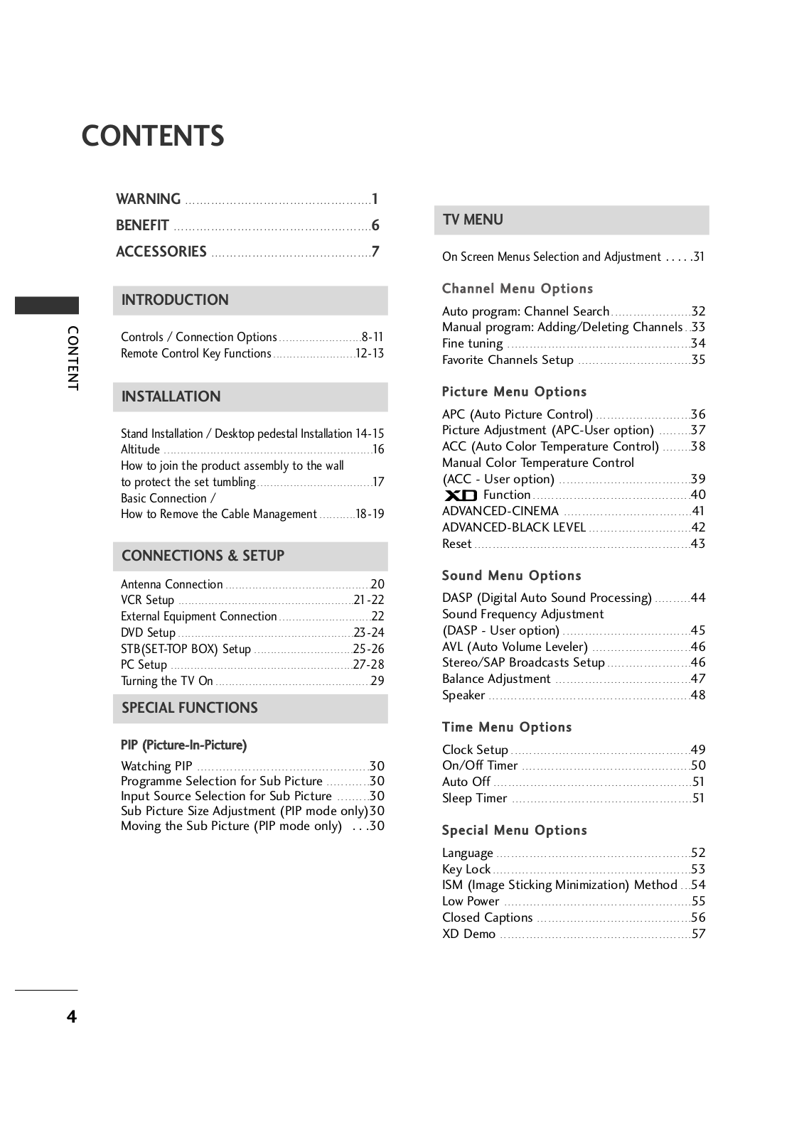
Table of contents
Loading...
LG 42PC3RVUJ User Manual
...
LG User Manual
Download
Specifications and Main Features
Frequently Asked Questions
User Manual
Download
Loading...
+
hidden pages
Unhide
You need points to download manuals.
1 point = 1 manual.
You can buy points or you can get point for every manual you upload.
Buy points
Upload your manuals
 Loading...