

LG 42PC3DV-UE User Manual
Please read this manual carefully before operating your set.
Retain it for future reference.
Record model number and serial number of the set.
See the label attached on the back cover and quote
this information to your dealer
when you require service.
ENERGYSTAR is a set of power-saving
guidelines issued by the U.S.
Environmental Protection Agency(EPA).
As an ENERGY STAR
Partner LGE U. S. A.,Inc.
has determined that this
product meets the ENERGY STAR guidelines for
energy efficiency.
P/NO : 38289U0527F (0707-REV08)
Printed in Korea
OWNER’S MANUAL
LCD TV
MODELS: 32LC2D
32LC2DU
37LC2D
42LC2D
PLASMA TV
MODELS: 42PC3D
42PC3DC
42PC3DV
50PC3D
60PC1D
60PC1DC
Internet Home Page : http://www.lge.com
http://www.lg.ca
http://www.lgcommercial.com
2
Warning
WARNING:
TO REDUCE THE RISK OF ELECTRIC SHOCK DO NOT REMOVE COVER (OR BACK). NO USER
SERVICEABLE PARTS INSIDE. REFER TO QUALIFIED SERVICE PERSONNEL.
The lightning flash with arrowhead symbol, within an equilateral triangle, is intended to alert the user to
the presence of uninsulated “dangerous voltage” within the product’s enclosure that may be of sufficient magnitude to constitute a risk of electric shock to persons.
The exclamation point within an equilateral triangle is intended to alert the user to the presence of
important operating and maintenance (servicing) instructions in the literature accompanying the appliance.
NOTE TO CABLE/TV INSTALLER:
This reminder is provided to call the CATV system installer’s attention to Article 820-40 of the National Electric
Code (U.S.A.). The code provides guidelines for proper grounding and, in particular, specifies that the cable
ground shall be connected to the grounding system of the building, as close to the point of the cable entry as practical.
REGULATORY INFORMATION
This equipment has been tested and found to comply with the limits for a Class B digital device, pursuant to Part
15 of the FCC Rules. These limits are designed to provide reasonable protection against harmful interference in
a residential installation. This equipment generates, uses and can radiate radio frequency energy and, if not
installed and used in accordance with the instructions, may cause harmful interference to radio communications.
However, there is no guarantee that interference will not occur in a particular installation. If this equipment does
cause harmful interference to radio or television reception, which can be determined by turning the equipment off
and on, the user is encouraged to try to correct the interference by one or more of the following measures:
- Reorient or relocate the receiving antenna.
- Increase the separation between the equipment and receiver.
- Connect the equipment into an outlet on a circuit different from that to which the receiver is connected.
- Consult the dealer or an experienced radio/TV technician for help.
Any changes or modifications not expressly approved by the party responsible for compliance could void the
user’s authority to operate the equipment.
CAUTION:
Do not attempt to modify this product in any way without written authorization from LG Electronics Corporation.
Unauthorized modification could void the user’s authority to operate this product.
COMPLIANCE:
The responsible party for this product’s compliance is:
LG Electronics U.S.A., Inc.
1000 Sylvan Avenue, Englewood Cliffs, NJ 07632
Phone: 1-800-243-0000
http://www.lgusa.com
CAUTION
RISK OF ELECTRIC SHOCK
DO NOT OPEN
W
W
arning
arning
3
Safety Instructions
WARNING :
To reduce the risk of fire or electric shock, do not expose this apparatus to rain or moisture.
Apparatus shall not be exposed to dripping or splashing and no objects filled with liquids, such as vases, shall be placed on the
apparatus.
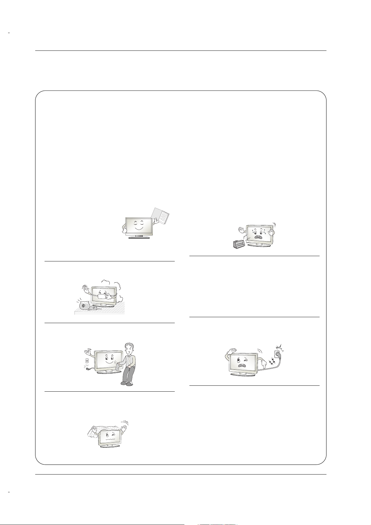
IMPORTANT SAFETY INSTRUCTIONS
1. Read these instructions.
2. Keep these instructions.
3. Heed all warnings.
4. Follow all instructions.
5. Do not use this apparatus near water.
6. Clean only with a dry cloth.
7. Do not block any of the ventilation openings. Install in
accordance with the manufacturer’s instructions.
8. Do not install near any heat sources such as radiators,
heat registers, stoves, or other apparatus (including
amplifiers) that produce heat.
9. Do not defeat the safety purpose of the polarized or
grounding type plug. A polarized plug has two blades
with one wider than the other. A grounding type plug has
two blades and a third grounding prong. The wide blade
or the third prong is provided for your safety. When the
provided plug does not fit into your outlet, consult an
electrician for replacement of the obsolete outlet.
10. Protect the power cord from being walked on or
pinched particularly at plugs, convenience receptacles, and the point where they exit from the apparatus.
11. Only use the attachments / accessories specified by
the manufacturer.
Safety Instructions
Safety Instructions
Owner's Manual
4
Safety Instructions
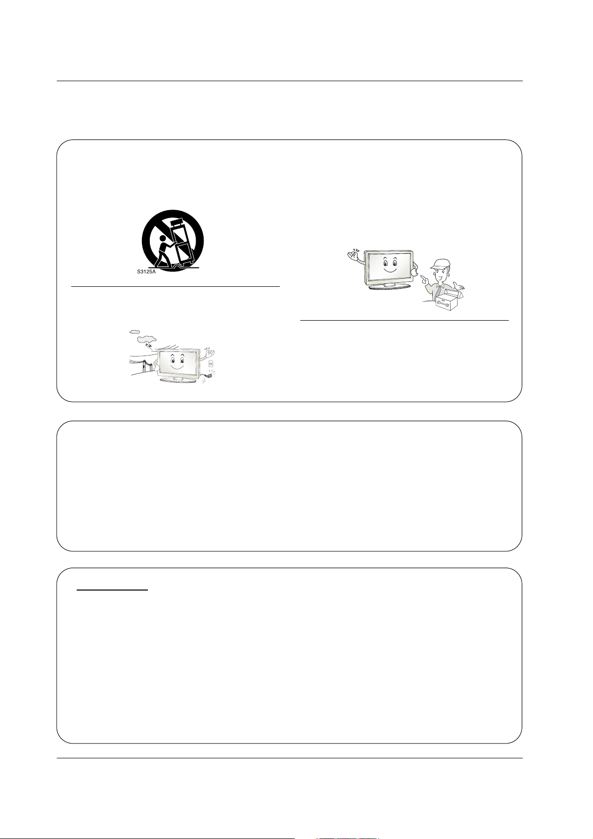
12. Use only with a cart, stand, tripod, bracket, or table
specified by the manufacturer, or sold with the apparatus. When a cart is used, use caution when moving
the cart / apparatus combination to avoid injury from
tip-over.
13. Unplug this apparatus during lightning storms or when
unused for long periods of time.
14. Refer all servicing to qualified service personnel.
Servicing is required when the apparatus has been
damaged in any way, such as power supply cord or
plug is damaged, liquid has been spilled or objects
have fallen into the apparatus, the apparatus has been
exposed to rain or moisture, does not operate normally, or has been dropped.
15. DISCONNECTING DEVICE FROM MAINS
Main plug is the disconnecting device.The
plug must remain readily operable.
On Disposal
a. The fluorescent lamp used in this product contains a small amount of mercury.
b. Do not dispose of this product with general household waste.
Disposal of this product must be carried out in accordance to the regulations of your local authority.
Note
- If the TV feels cold to the touch, there may be a small “flicker” when when it is turned on. This is normal, there is nothing wrong with TV.
- Some minute dot defects may be visible on the screen, appearing as tiny red, green, or blue spots. However, they have
no adverse effect on the monitor's performance.
- Avoid touching the LCD screen or holding your finger(s) against it for long periods of time. Doing so may produce some
temporary distortion effects on the screen.
CAUTION concerning the Power Cord
Most appliances recommend they be placed upon a dedicated circuit; that is, a single outlet circuit which powers only that
appliance and has no additional outlets or branch circuits. Check the specification page of this owner's manual to be certain.
Do not overload wall outlets. Overloaded wall outlets, loose or damaged wall outlets, extension cords, frayed power cords,
or damaged or cracked wire insulation are dangerous. Any of these conditions could result in electric shock or fire.
Periodically examine the cord of your appliance, and if its appearance indicates damage or deterioration, unplug it, discontinue use of the appliance, and have the cord replaced with an exact replacement part by an authorized servicer.
Protect the power cord from physical or mechanical abuse, such as being twisted, kinked, pinched, closed in a door, or
walked upon. Pay particular attention to plugs, wall outlets, and the point where the cord exits the appliance.
FOR LCD TV
5
Contents
Contents
Contents
Introduction
Installation
Operation
29 Turning on the TV
29 Volume Adjustment
29 Channel Selection
29 On Screen Menus Language Selection
30 On Screen Menus Selection and Adjustment
31 EZ Scan (Channel Search)
31 Manual Scan
32 Channel Edit
33 DTV Signal Strength
33 Input Source
34 Input Label
35 Auto Picture Control(EZ Picture)
35~36 Color Temperature Control
37 XD
38 Advanced-Cinema 3:2 Mode / Black Level
39 Video Reset
40 Audio Language
41 Auto Sound Control(EZ Sound)
41~42 Manual Sound Control (EZ Sound-User option)
43 Balance
43 TV Speakers On/Off Setup
2 Warning
3~4 Safety Instructions
7 Accessories
8~11 Controls
Connection Options
12~13 Remote Control Key Functions
14 Attaching the TV to a wall
15 Desktop Pedestal Installation
16~17 Basic Connection
18 Antenna or Cable Connection
19~20 VCR Setup
20 External AV Source Setup
21~22 DVD Setup
23~24 HDSTB Setup
25 AV Out Setup
25 Digital Audio Output
26~28 PC Setup
Setup Menu
Options
Video Menu
Options
Audio Menu
Options
Basic operation
External
Equipment
Connections

6
Contents
Reference
44 Manual Clock Setup
44 Auto Clock Setup
45 On/Off Timer Setup
45 Sleep Timer
46 Auto Off
47 Aspect Ratio Control
48 Caption/Text
49 Caption Option
49 Low Power (42PC3D/3DC/3DV, 50PC3D, 60PC1D/1DC Only)
50 ISM (Image Sticking Minimization) Method
(42PC3D/3DC/3DV, 50PC3D,
60PC1D/1DC Only)
51~52 Parental Lock Setup
53~58 External Control Device Setup
59~60 IR Codes
61 Programming the Remote
62~63 Programming Codes
64~65 Troubleshooting Checklist
65 Maintenance
66~67 Product Specifications
Option Menu
Features
Lock Menu Options
Operation
Time Menu
Options
7
Introduction
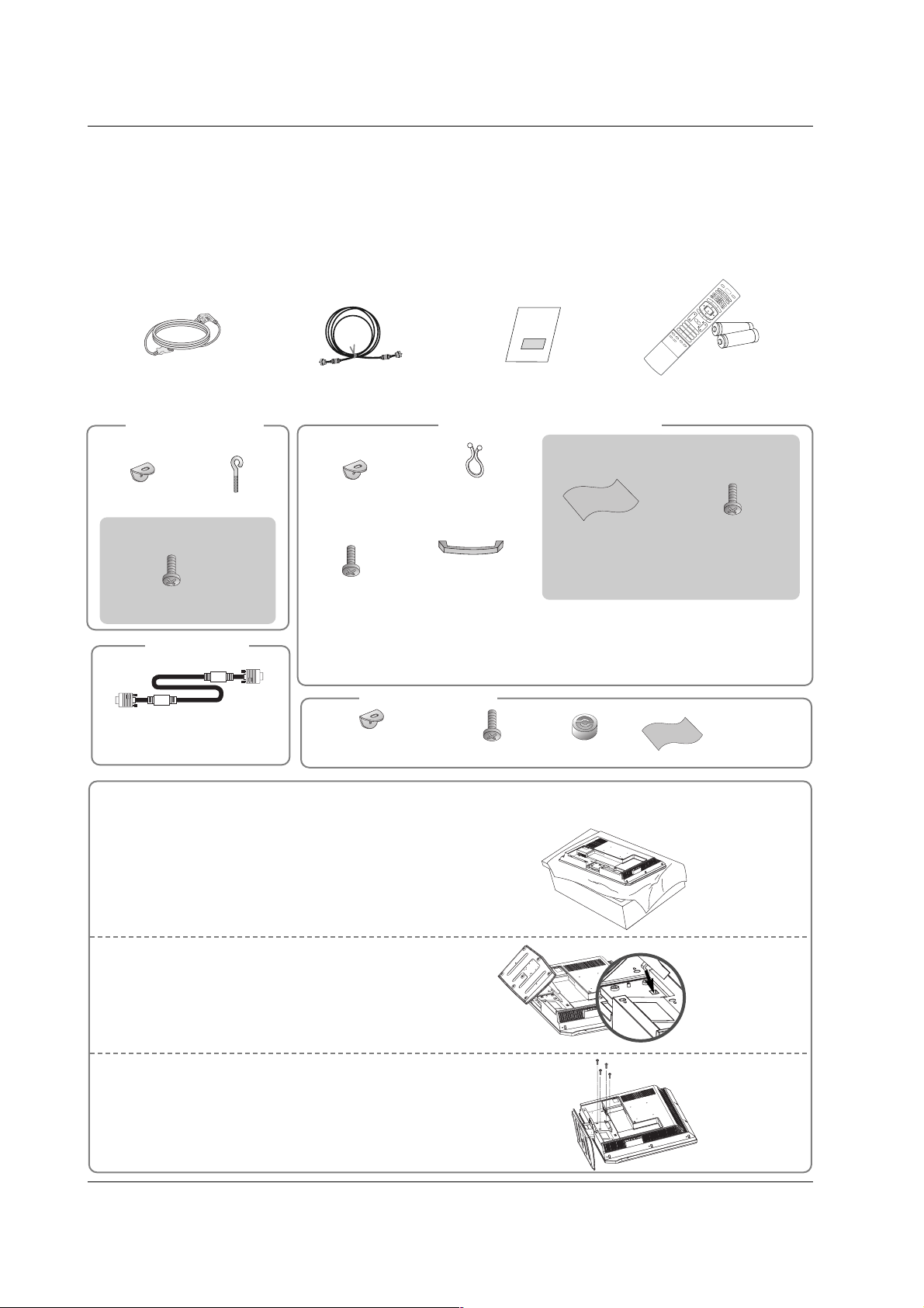
Accessories
Accessories
Introduction
Introduction
Owner’s Manual
75Ω Round Cable
Power Cord
Ensure that the following accessories are included with your TV. If any accessory is missing, please contact the
dealer from where you purchased the product. User must use shielded signal interface cables(D-sub 15 pin cable)
with ferrite cores to maintain standard compliance for the product.
1.5V
1.5V
VOL
FLASHBK
CH
PO
1 2 3
456
78
0
9
APM
ADJUST
SAP
EZ SOUND
EZ PIC
FREEZE
A
U
D
I
O
D
A
Y
-
CAB
L
E
GUIDE
M
E
N
U
MUTE
PAGE
PAGE
FAV
D
A
Y
+
STB
EXIT
T
I
M
E
R
C
C
T
V
DVD
MO
D
E
I
N
F
O
ENTER
VOL
CH
POWER
123
456
78
0
9
M
E
N
U
MUTE
FAV
R
A
T
I
O
D
A
Y
-
GUIDE
D
A
Y
+
R
A
T
I
O
V
C
R
T
V
DVD
ENTER
APM
ADJUST
SAP
EZ SOUND
EZ PIC
FREEZE
FLASHBK
PAGE
PAGE
EXIT
T
I
M
E
R
C
C
I
N
F
O
A
U
D
I
O
CABLE
STB
MODE
TV INPUT
INPU
T
TV INPUT
Remote Control /
Batteries
2-eye-bolts
2-TV brackets
2-Wall brackets
2-TV Bracket Bolts
For 32/37/42LC2D, 32LC2DU
For
42PC3D/3DC/3DV,
50PC3D
Twister Holder
Arrange the wires
with the twister holder.
Cable
Management
(Refer p.16)
2-Wall brackets
42PC3D/3DC/3DV only
2-bolts
(Refer p.14)
4-bolts for stand
assembly
See below for detail
information.
32LC2D/U only
42LC2D only
Polishing Cloth
Polish the TV with
the cloth.
Carefully place the product screen side down on a
cushioned surface that will protect product and
screen from damage.
1
Place the hook of the stand in the back of the
product as shown.
2
Install the 4 bolts provided securely, in the back of the
product.
3
Stand Installation for 32LC2D/U
[Polishing Cloth]
Slightly wipe stained spot on the exterior only with the cleansing cloths for the product exterior if
there is stain or fingerprint on surface of the exterior.
Do not wipe roughly when removing stain. Please be cautious of that excessive power may cause
scratch or discoloration.
Option Extras
D-sub 15 pin cable
4-RING SPACER
For 60PC1D/1DC
2-TV brackets
2-Wall brackets
4- Bolts
Polishing Cloth
Polish the TV
with the cloth.
8
Introduction
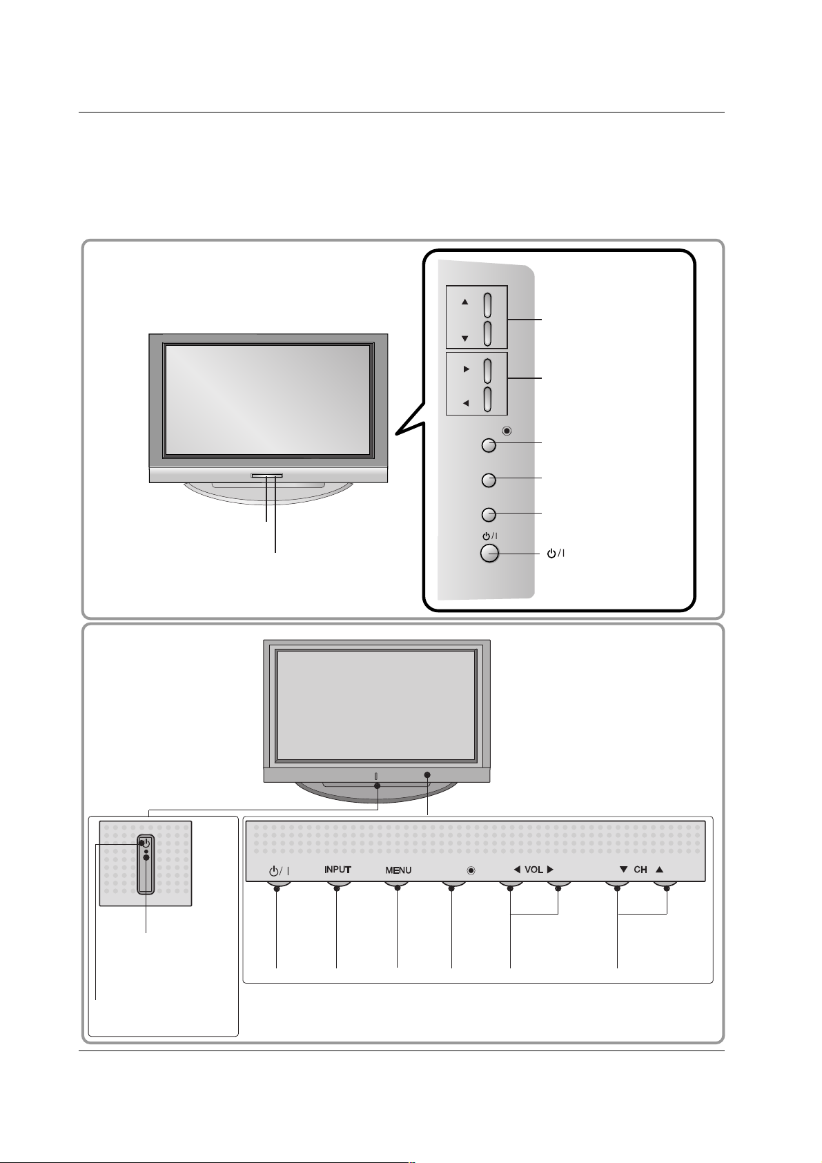
Controls
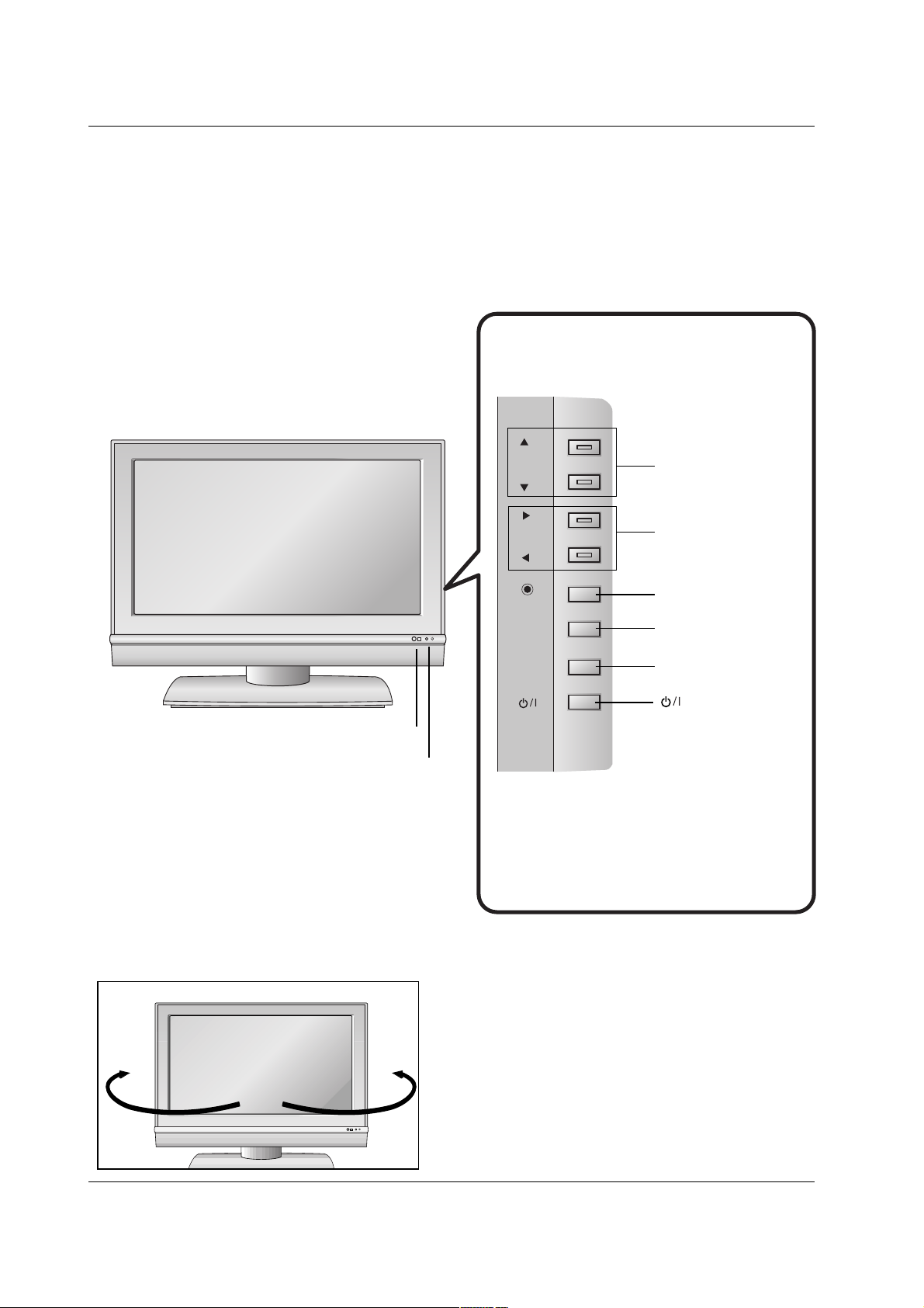
Controls (Model Name: 42PC3D/3DC/3DV, 50PC3D, 60PC1D/1DC)
- This is a simplified representation of front panel.
- This picture shown below may be somewhat different from your TV.
POWER
Button
INPUT
Button
ENTER
Button
VOLUME
(
FF,GG
)Buttons
CHANNEL
(
EE,DD
)Buttons
Power Standby Indicator
Illuminates red in standby mode.
Illuminates white when
the set is switched on.
MENU
Button
ENTERENTER
Remote
Control Sensor
CHCH
VOLOL
ENTERENTER
MENUMENU
INPUTINPUT
CHANNEL (D, E)
Buttons
VOLUME (F,G)
Buttons
ENTER Button
MENU Button
INPUT Button
Remote Control Sensor
Power/Standby Indicator
• illuminates red in standby mode.
• illuminates green when the set is switched on.
(Power) Button
42PC3D/3DC/3DV, 50PC3D
60PC1D/1DC
9
Introduction
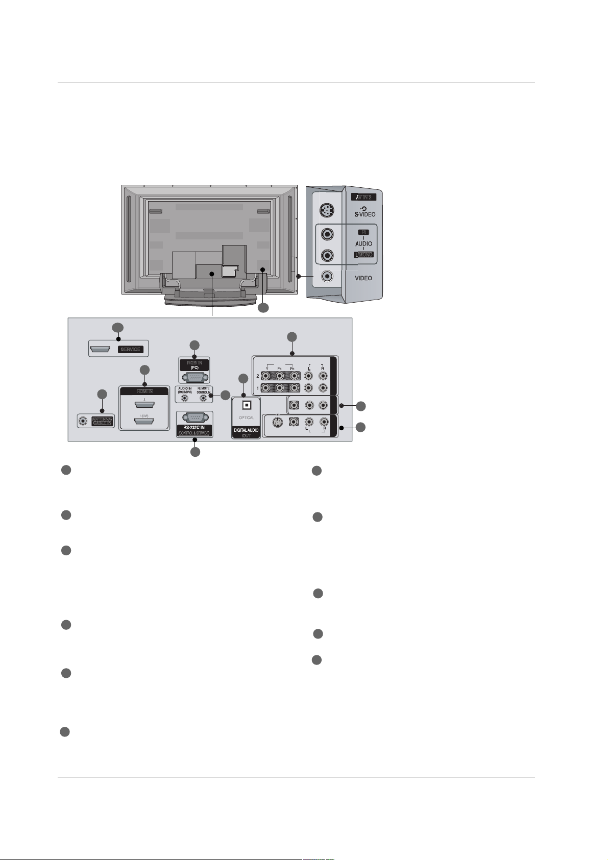
Connection Options
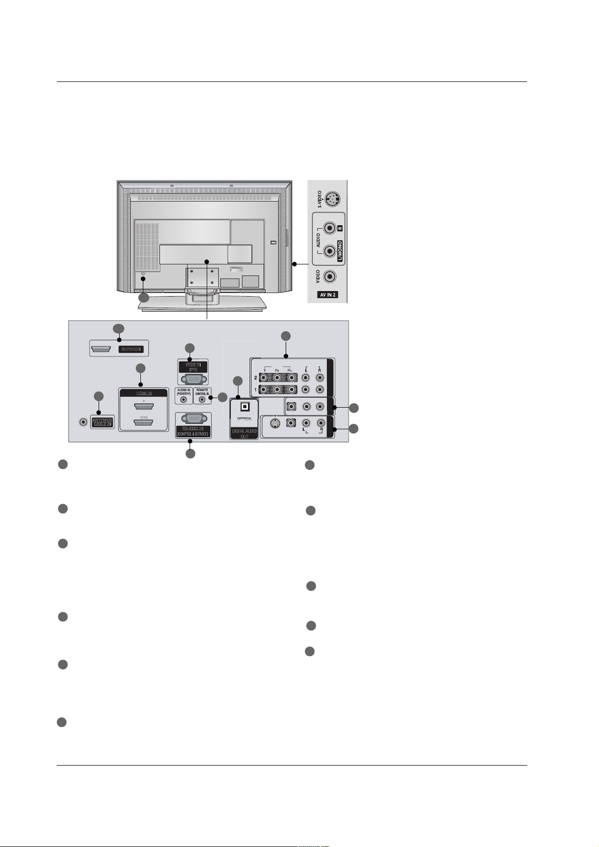
Connection Options
(Model Name: 42PC3D/3DC/3DV, 50PC3D, 60PC1D/1DC)
- This picture shown below may be somewhat different from your TV.
/
MONO
VIDEOVIDEO
AUDIOAUDIO
VIDEOVIDEO
AUDIOAUDIO
MONO
( )
S-VIDEOS-VIDEO
AV IN 1AV IN 1
AV OUTAV OUT
ANTENNA/
CABLE IN
(CONTROL & SERVICE)
RGB IN
COMPONENT INCOMPONENT IN
OUT
O
PTICAL
1(DVI)
SERVICE
S-VIDEO Input
Provides better picture quality
than the video input.
AUDIO Input
Connections are available for listening to stereo sound from an
external device.
VIDEO Input
Connects the video signal from a
video device.
1
2
4
5
6
7
8
3
9
11
10
COMPONENT IN
Connect a component video/audio device to
these jacks.
AV OUT
Connect a second TV or monitor.
AV (Audio/Video) IN 1
Connect audio/video output from an external
device to these jacks.
S-VIDEO
Connect S-Video out from an S-VIDEO device.
ANTENNA/CABLE IN
Connect over-the air signals to this jack.
Connect cable signals to this jack.
DIGITAL AUDIO OUT
Connect digital audio from various types of equipment.
Note: In standby mode, these ports do not work.
HDMI IN
Connect a HDMI signal to 1(DVI) or 2.
Or DVI (VIDEO)signal to the 1(DVI) port with a
DVI to HDMI cable.
RGB IN (PC)
Connect the monitor output from a PC to the
appropriate input port.
Remote Control Port
Connect your wired remote control.
AUDIO IN (RGB/DVI)
Connect the monitor output from a PC to the
appropriate input port.
RS-232C IN (CONTROL & SERVICE) PORT
Connect to the RS-232C port on a PC.
SERVICE
Power Cord Socket
For operation with AC power.
Caution:
Never attempt to operate the TV on DC power.
1
7
8
9
10
2
3
4
5
6
11
Introduction
Controls
Controls (Model Name: 32/37/42LC2D
, 32LC2DU
)
- This is a simplified representation of front panel.
- This picture shown below may be somewhat different from your TV.
10
CH
VOL
ENTER
MENU
INPUT
CHANNEL (D, E)
Buttons
VOLUME (F,G)
Buttons
ENTER Button
MENU Button
INPUT Button
Remote Control Sensor
Power/Standby Indicator
• illuminates red in standby
mode.
• illuminates green when the set
is switched on.
(Power) Button
Swivel Stand (42LC2D Only)
Swivel Stand (42LC2D Only)
R
- The TV can be conveniently swivelled on its stand
30
° to
the left or right to provide the optimum viewing angle.
ENTER
R
MENU
INPUT
CH
VOL
11
Introduction
Connection Options
Connection Options
(Model Name: 32/37/42LC2D
, 32LC2DU
)
- This picture shown below may be somewhat different from your TV.
VIDEO
AUDIO
VIDEO
AUDIO
( )
S-VIDEO
AV IN 1
AV OUT
COMPONENT IN
AC IN
VIDEO
AUDIO
VIDEO
AUDIO
( )
S-VIDEO
AV IN 1
AV OUT
COMPONENT IN
VIDEOVIDEO
AUDIOAUDIO
VIDEOVIDEO
AUDIOAUDIO
MONO
( )
S-VIDEOS-VIDEO
AV IN 1AV IN 1
AV OUTAV OUT
ANTENNA/
CABLE IN
RS-232C IN
(CONTROL & SERVICE)
RGB IN
(PC)
COMPONENT INCOMPONENT IN
DIGITAL AUDIO
OUT
O
PTICAL
SERVICE
1(DVI)
S-VIDEO Input
Provides better picture quality than the
video input.
VIDEO Input
Connects the video signal from a video
device.
AUDIO Input
Connections are available for listening to
stereo sound from an external device.
COMPONENT IN
Connect a component video/audio device to
these jacks.
AV OUT
Connect a second TV or monitor.
AV (Audio/Video) IN 1
Connect audio/video output from an external
device to these jacks.
S-VIDEO
Connect S-Video out from an S-VIDEO device.
ANTENNA/CABLE IN
Connect over-the air signals to this jack.
Connect cable signals to this jack.
DIGITAL AUDIO OUT
Connect digital audio from various types of equipment.
Note: In standby mode, these ports do not work.
HDMI IN
Connect a HDMI signal to 1(DVI) or 2.
Or DVI (VIDEO)signal to the 1(DVI) port with a
DVI to HDMI cable.
RGB IN (PC)
Connect the monitor output from a PC to the
appropriate input port.
Remote Control Port
Connect your wired remote control.
AUDIO IN (RGB/DVI)
Connect the monitor output from a PC to the
appropriate input port.
RS-232C IN (CONTROL & SERVICE) PORT
Connect to the RS-232C port on a PC.
SERVICE
Power Cord Socket
For operation with AC power.
Caution:
Never attempt to operate the TV on DC power.
1
2
4
1
7
8
9
10
2
3
4
5
5
6
7
8
3
9
11
6
11
10
12
Introduction
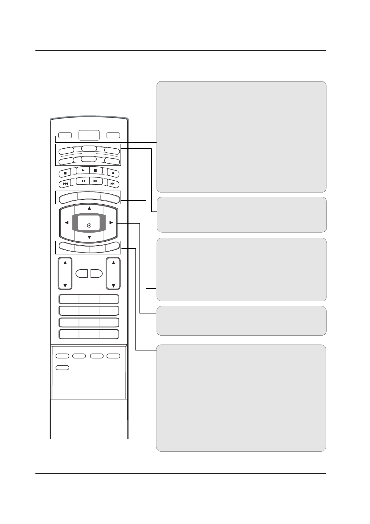
Remote Control Key Functions
Remote Control Key Functions
POWER
Turns your TV or any other programmed equipment on or
off, depending on mode.
VOL
CH
POWER
1 2 3
4 5 6
7809
ME
N
U
MUTE
FAV
B
R
IGHT +
VCR
TV
DVD
ENTER
ADJUST
SAP
EZ SOUND
EZ PIC
CC
FLASHBK
EXIT
TIMER
R
ATIO
INFO
AUDIO
CABLE
STB
MODE
TV INPUT
INPUT
B
RI
GHT -
TV INPUT
In AV1-2, Component 1-2, or RGB-PC, HDMI1/DVI, and HDMI2
input sources, screen returns to the last TV channel.
MODE
Selects the remote operating mode: TV, DVD, VCR, AUDIO,
CABLE, or STB. Select a mode other than TV, for the remote
to operate an external device.
INPUT
External input modes rotate in regular sequence: TV, AV1-2,
Component 1-2, RGB-PC, HDMI1/DVI or HDMI2.
(AV 1-2, Component 1-2, RGB-PC , HDMI1/DVI or HDMI2
input sources are linked automatically, only if these are connected.)
EXIT
Clears all on-screen displays and returns to TV viewing from
any menu.
TIMER
GG
p.45
Lets you select the amount of time before your TV turns
itself off automatically.
RATIO
GG
p.47
Changes the aspect ratio.
MENU
Brings up the main menu to the screen.
BRIGHT + / -
- Adjust brightness on screen.
- It turns to the default settings brightness by changing mode
source.
THUMBSTICK (Up/Down/Left/Right/ENTER)
Allows you to navigate the on-screen menus and adjust the
system settings to your preference.
INFO
When you watch the TV, information displays on top of the
screen. Not available in Component 1-2, RGB, HDMI1/DVI
and HDMI2 mode.
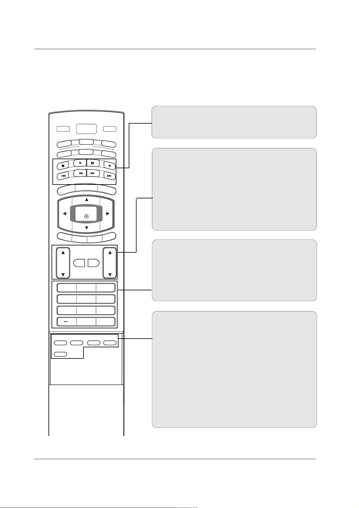
13
Introduction
EZ PIC GGp.35
Selects a factory preset picture mode depending on the viewing environment.
EZ SOUND
GG
p.41
Selects the sound appropriate for the program's character.
SAP
Selects MTS sound: Mono, Stereo, and SAP in analog mode.
Change the audio language in DTV mode.
CC
GG
p.48
(*In DTV/CADTV mode
GG
p.48
)
Select a closed caption: Off, CC1~4, Text1~4.
ADJUST
Adjusts screen position, size, and phase in PC mode.
FAV
Use to scroll the Favorite channels.
MUTE
GG
p.29
Switches the sound on or off.
CHANNEL UP/DOWN
Selects available channels found with EZ scan and Manual scan.
VOLUME UP/DOWN
Increases/decreases the sound level.
VOL
CH
POWER
1 2 3
4 5 6
7809
ME
N
U
MUTE
FAV
B
R
IGHT +
VCR
TV
DVD
ENTER
ADJUST
SAP
EZ SOUND
EZ PIC
CC
FLASHBK
EXIT
TIMER
R
ATIO
INFO
AUDIO
CABLE
STB
MODE
TV INPUT
INPUT
B
RI
GHT -
— (DASH)
Used to enter a program number for multiple program channels such as 2-1, 2-2,etc.
NUMBER BUTTONS
FLASHBK
Returns to the last channel viewed.
VCR/DVD/DVHS/Camcorder BUTTONS
Control some video cassette recorders or DVD players
("RECORD" button is not available for DVD player).
14
Introduction
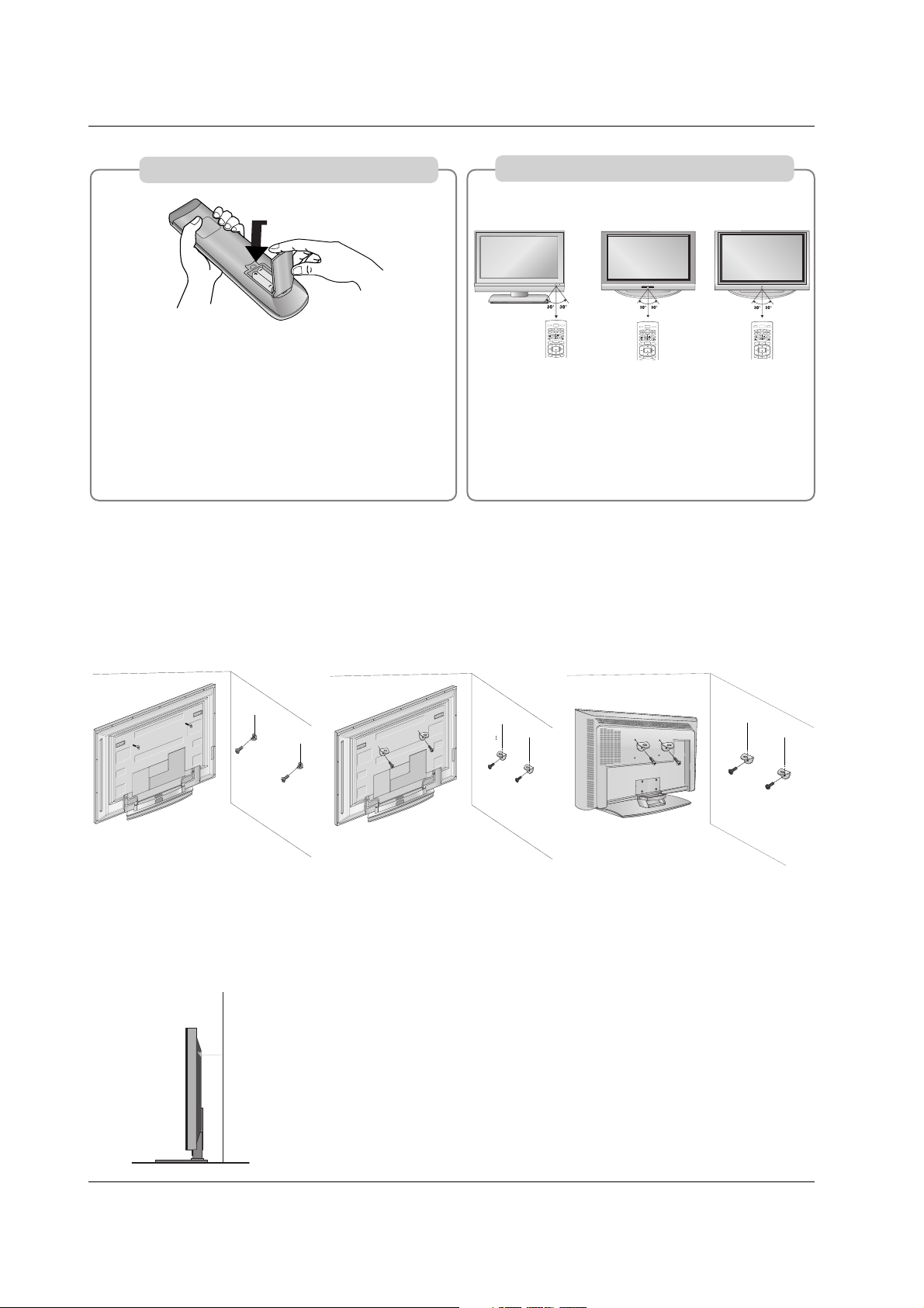
ATTACHING THE TV TO A WALL
We recommend that you set up the TV close to a wall so it cannot fall over if pushed backwards.
Additionally, we recommend that the TV be attached to a wall so it cannot be pulled in a forward direction, potentially causing injury or damaging the product.
Caution: Please make sure that children don’t climb on or hang from the TV.
■
Insert the eye-bolts (or TV brackets and bolts) to tighten the product to the wall as shown in the picture.
* If your product has the bolts in the eye-bolts position, loosen the bolts.
Secure the wall brackets with the bolts (not provided as parts of the product, must purchase separately)
on the wall. Match the height of the bracket that is mounted on the wall to the holes in the product.
Ensure the eye-bolts or brackets are tightened securely.
■
Use a sturdy rope (not provided as parts of the product, must purchase separately) to tie the product. It is safer to tie the rope so it becomes horizontal
between the wall and the product.
42PC3D/3DC/3DV, 50PC3D
32/37/42LC2D, 32LC2DU
■
Open the battery compartment cover on the
back side and install the batteries matching correct polarity (+with +,-with -).
■
Install two 1.5V AA batteries. Don’t mix old or
used batteries with new ones.
■
Close cover.
■
Use a remote control up to 7 meters distance and
30 degree (left/right) within the receiving unit
scope.
■
Dispose of used batteries in a recycle bin to preserve environment.
POWER
ME
N
U
B
RI
GH
T +
VCR
TV
DVD
ENTER
EXIT
TIM
E
R
R
ATIO
I
NFO
AU
D
IO
CABLE
STB
MODE
TV INPUT
INPUT
BRIGHT -
POWER
ME
N
U
B
R
I
GH
T +
VCR
T
V
DVD
ENTER
EX
IT
TIM
E
R
R
ATIO
I
NFO
AU
D
IO
CABLE
STB
MODE
TV INPUT
INPUT
B
RI
GHT -
POWER
ME
N
U
B
R
IG
H
T +
VCR
TV
DVD
ENTER
EX
IT
TIM
E
R
RATIO
INFO
AU
D
IO
CABLE
STB
MODE
TV INPUT
INPUT
B
RIGHT -
32/37/42LC2D,
32LC2DU
42PC3D/3DC/3DV, 50PC3D 60PC1D/1DC
Installing Batteries
Remote control effective range
60PC1D/1DC
15
Installation
Installation
Installation
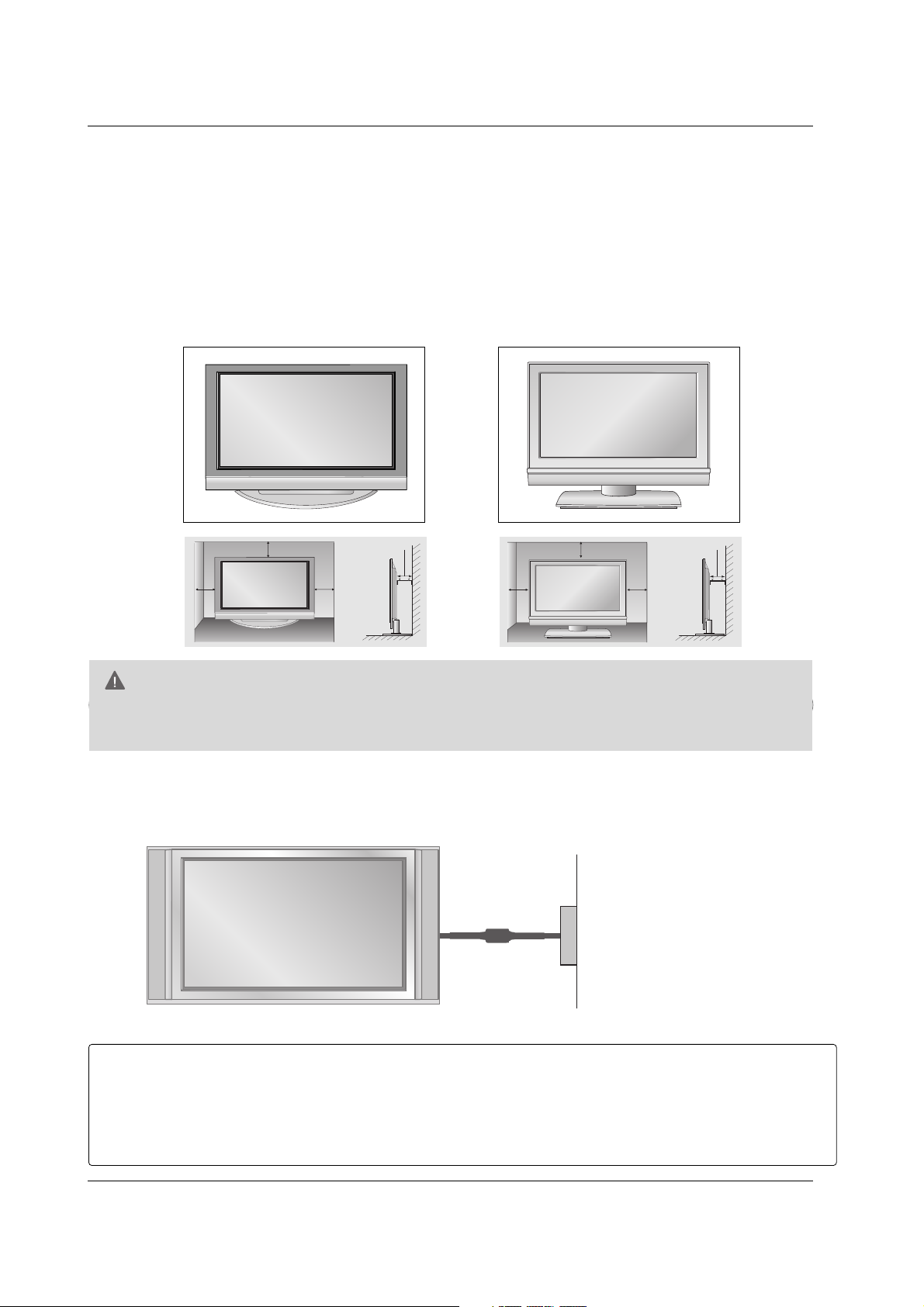
For proper ventilation, allow a clearance of 4inches on each side from the wall.
GG
Ensure adequate ventilation by following the clearance recommendations.
CAUTION
Power Supply
Short-circuit
Breaker
■
This picture shown below may be somewhat different from your TV.
GROUNDING
Ensure that you connect the earth ground wire to prevent possible electric shock. If grounding methods
are not possible, have a qualified electrician install a separate circuit breaker.
Do not try to ground the unit by connecting it to telephone wires, lightening rods, or gas pipes.
DESKTOP PEDESTAL INSTALLATION
32/37/42LC2D, 32LC2DU42PC3D/3DC/3DV, 50PC3D, 60PC1D/1DC
4 inches
4 inches4 inches
4 inches
4 inches
4 inches
4 inches
4 inches
16
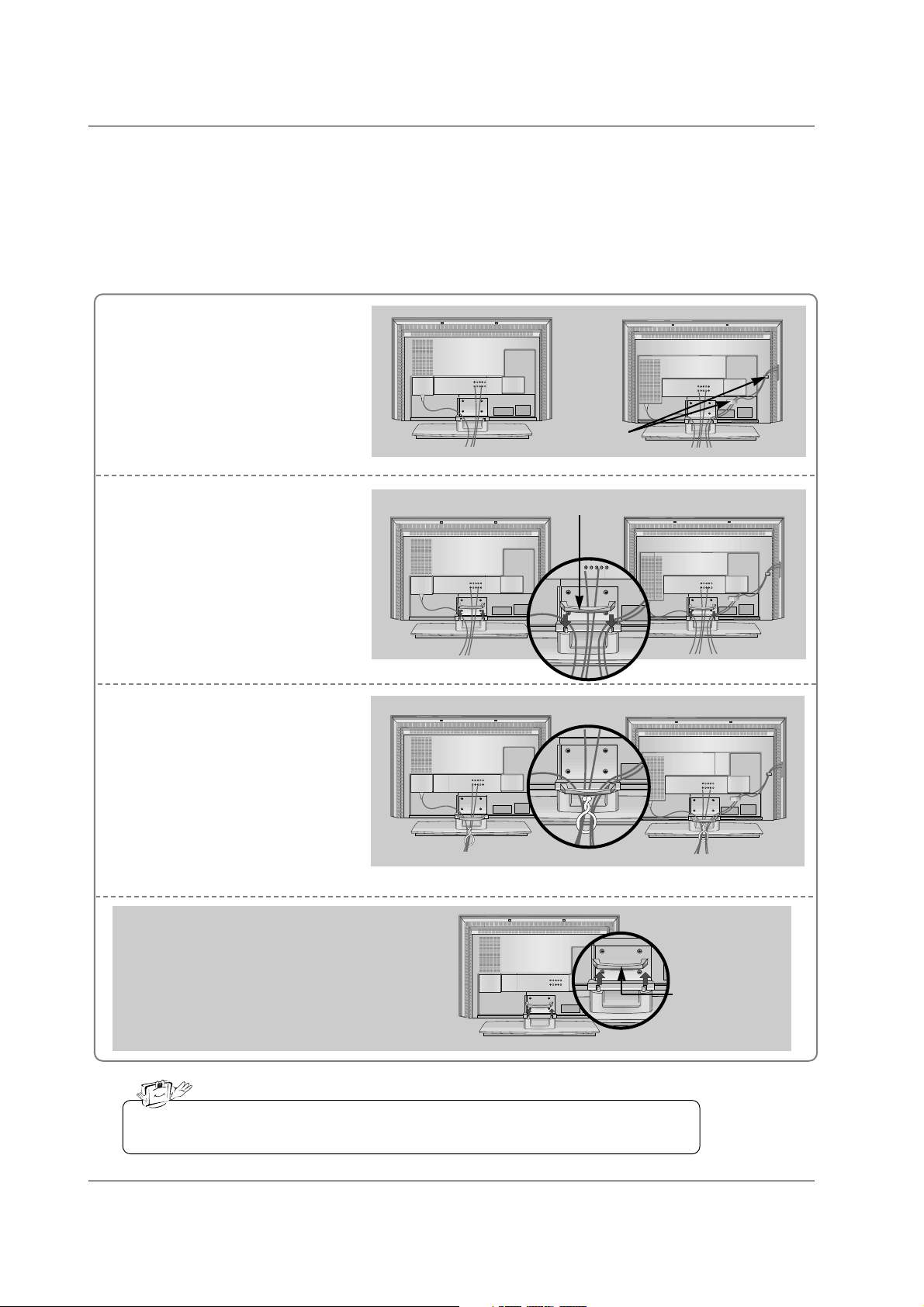
Connect the cables as necessary.
After connecting the cables neatly, arrange the cables to the
Cable Holder.
To connect an additional equipment, see the External equip-
ment Connections section.
Reinstall the CABLE MANAGE-
MENT as shown.
1
2
Bundle the cables using the supplied twister holder.
3
Basic Connection (For 32/37/42LC2D, 32LC2DU)
Basic Connection (For 32/37/42LC2D, 32LC2DU)
32LC2D/U
Cable holder
37/42LC2D
32LC2D/U
37/42LC2D
32LC2D/U
37/42LC2D
Do not hold the CABLE MANAGEMENT when moving the product.
- If the product is dropped, you may be injured or the product may be broken.
How to remove
the CABLE MANAGEMENT
- Hold the CABLE MANAGEMENT with both hands
and pull it upward.
CABLE
MANAGEMENT
CABLE MANAGEMENT
17
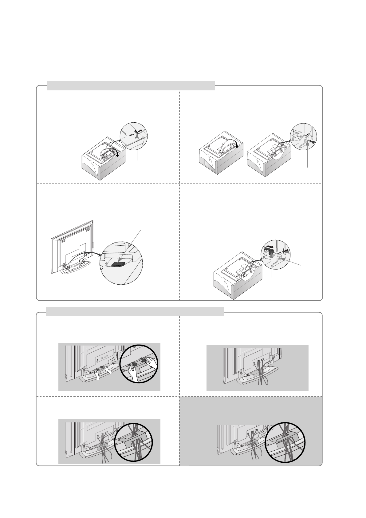
Place the set with the screen facing down on
a cushion or soft cloth as shown.
Before unfolding the stand, please make sure
two locks (A) on the bottom of the stand push
outward.
Pull the stand out as shown.
After unfolding the stand, please insert and
tighten the screws (provided as parts of the
product) in the holes (B) on the bottom of the
stand.
1
2
When connecting cables to the set, Do not
disengage the lock (C).
This may cause the set to fall, causing serious
bodily injury and serious damage to the set.
3
Basic Connection
Basic Connection
(C)
Hold the CABLE MANAGEMENT with both
hands and push it as shown.
Connect the cables as necessary.
To connect an additional equipment, see the
External equipment Connections section.
Reinstall the CABLE MANAGEMENT as
shown.
1
2
3
* Image shown here may be slightly different from
your set.
When closing the stand for storage
- First remove the screws in the holes (B) on the bottom
of the stand. And then pull two Hooks (D) of the stand
bottom and fold the stand into the back of the set.
- After folding, push the two Locks (A) of the stand
bottom outward.
(A)
(B)
(D)
(A)
(B)
How to use stand (For 42PC3D/3DC/3DV)
How to arrange the cable (For 50PC3D)
For 60PC1D/1DC, 42PC3D/3DC/3DV
Arrange the cable as shown.
18
Installation
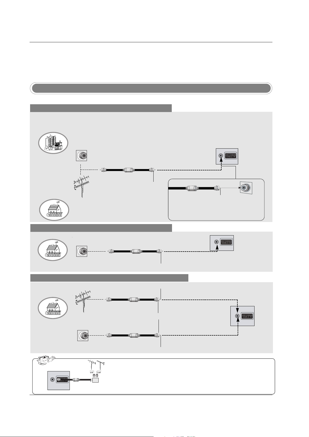
Antenna Or Cable Connection
Multi-family Dwellings/Apartments
(Connect to wall antenna socket)
Single-family Dwellings /Houses
(Connect to wall jack for outdoor antenna)
Outdoor Antenna
Wall Antenna Socket
VHF Antenna
UHF Antenna
RF Coaxial Wire (75 ohm)
Turn clockwise to tighten.
VIDEO
AUDIO
VIDEO
AUDIO
( )
S-VIDEO
AV IN 1
AV OUT
ANTENNA/
CABLE IN
COMPONENT IN
DIGITAL AUDIO
OUT
OPTICAL
Bronze Wire
Be careful not to bend the bronze wire when
connecting the antenna.
Analog and Digital TV signals provided on antenna
- Antenna or Cable Service without a Cable Box Connection.
- For optimum picture quality, adjust antenna direction if needed.
Analog and DTV signals provided on two separate antennas
Cable TV Wall Jack
RF Coaxial Wire (75 ohm)
Bronze Wire
Bronze Wire
Turn clockwise to tighten.
Antenna
RF Coaxial Wire (75 ohm)
• In a poor signal area to improve picture quality, purchase and install a signal amplifier.
• If the antenna needs to be split for two TV’s, install a “2-Way Signal Splitter”
in the connections.
• If the antenna is not installed properly, contact your dealer for assistance.
VIDEO
AUDIO
VIDEO
AUDIO
( )
S-VIDEO
AV IN 1
AV OUT
ANTENNA/
CABLE IN
COMPONENT IN
DIGITAL AUDIO
OUT
OPTICAL
External Equipment Connections
External Equipment Connections
signal
amplifier
VIDEO
AUDIO
VIDEO
AUDIO
( )
S-VIDEO
AV IN 1
AV OUT
ANTENNA/
CABLE IN
COMPONENT IN
DIGITAL AUDIO
OUT
OPTICAL
NOTE: All cables shown are not included with the TV
Cable TV Wall Jack
RF Coaxial Wire (75 ohm)
Turn clockwise to tighten.
Analog and Digital TV signals provided on cable
VIDEO
AUDIO
VIDEO
AUDIO
( )
S-VIDEO
AV IN 1
AV OUT
ANTENNA/
CABLE IN
COMPONENT IN
DIGITAL AUDIO
OUT
OPTICAL
19
Installation
- To avoid picture noise (interference), leave an adequate distance between the VCR and TV.
- Typically a frozen still picture from a VCR. If the 4:3 picture format is used; the fixed images on the sides
of the screen may remain visible on the screen.
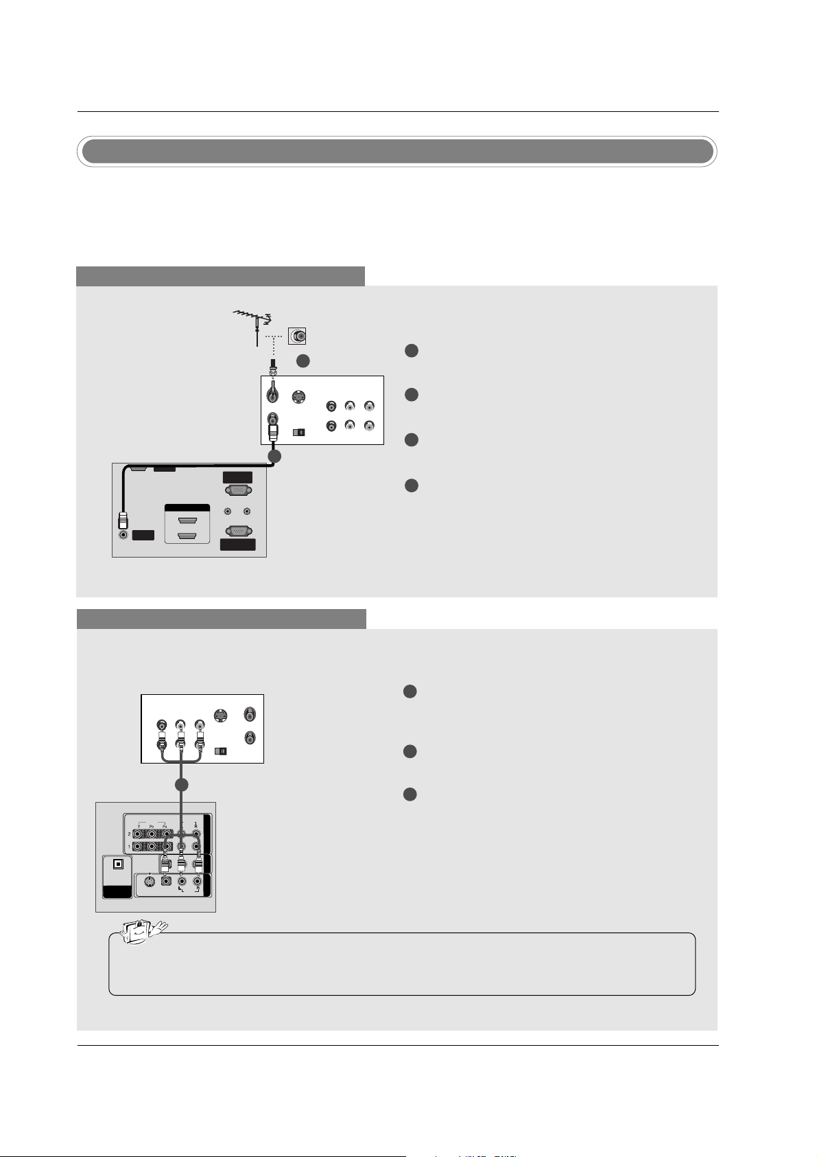
VCR Setup
When connecting with an antenna
S-VIDEO
OUT
IN
(R) AUDIO (L) VIDEO
34
OUTPUT
SWITCH
ANT OUT
ANT IN
ANTENNA/ANTENNA/
CABLE INCABLE IN
REMOTEREMOTE
CONTROL INCONTROL IN
RS-232C INRS-232C IN
(CONTROL(CONTROL & SER & SERVICE)VICE)
RGB IN
(PC)(PC)
AUDIO INAUDIO IN
(RGB/DVI)(RGB/DVI)
SERVICESERVICE
HDMI IN
1(DVI)1(DVI)
2
When connecting with a RCA cable
S-VIDEO
OUT
IN
(R) AUDIO (L) VIDEO
34
OUTPUT
SWITCH
ANT OUT
ANT IN
HDMI / DVI IN
ANTENNA/
CABLE IN
REMOTE
CONTROL IN
RS-232C IN
(CONTROL & SERVICE)
RGB IN
(PC)
AUDIO IN
(RGB/DVI)
VIDEOVIDEO
AUDIOAUDIO
VIDEOVIDEO
AUDIOAUDIO
MONO
( )
S-VIDEOS-VIDEO
AV IN 1
AV OUT
COMPONENTCOMPONENT IN
DIGITAL AUDIO
OUTOUT
OPTICALPTICAL
SERVICE
VCR
1
2
3
Connect the AUDIO/VIDEO jacks between TV
and VCR. Match the jack colors (Video = yellow,
Audio Left = white, and Audio Right = red)
Insert a video tape into the VCR and press PLAY
on the VCR. (Refer to the VCR owner’s manual.)
Select AV 1 input source using the INPUT button
on the remote control.
- If connected to AV IN2, select AV2 input source.
• If you have a mono VCR, connect the audio cable from the VCR to the AUDIO L/MONO jack of the
set.
1
1
2
3
4
Connect the RF antenna out socket of the VCR to
the Antenna socket on the set.
Connect the antenna cable to the RF antenna in
socket of the VCR.
Set VCR output switch to 3 or 4 and then tune TV
to the same channel number.
Insert a video tape into the VCR and press PLAY
on the VCR. (Refer to the VCR owner’s manual.)
VCR
1
2
20
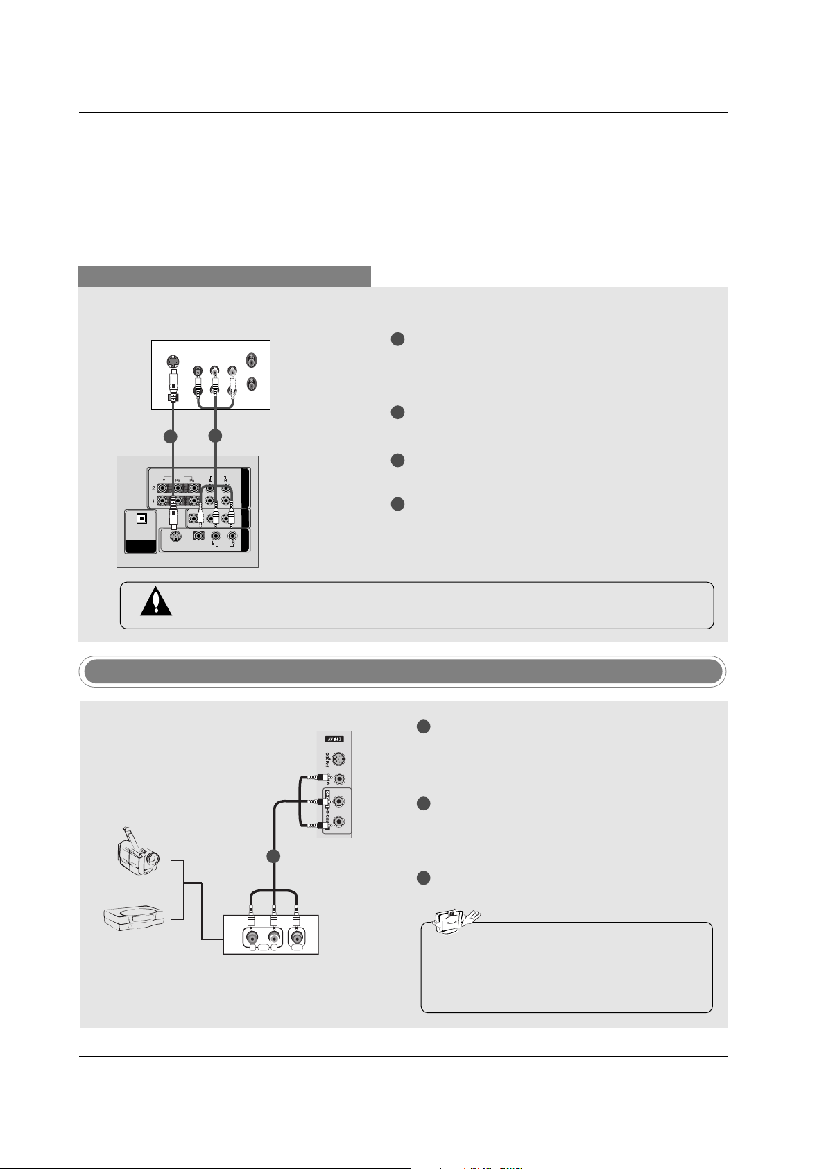
Installation
When connecting with an S-Video cable
VIDEO
AUDIOAUDIO
VIDEO
AUDIOAUDIO
MONO
( )
S-VIDEOS-VIDEO
AV IN 1
AV OUT
COMPONENTCOMPONENT IN
DIGITDIGITALAL AUDIO AUDIO
OUT
OPTICALPTICAL
S-VIDEO
OUT
IN
(R) AUDIO (L) VIDEO
34
OUTPUT
SWITCH
ANT OUT
ANT IN
HDMI / DVI IN
ANTENNA/
CABLE IN
REMOTE
CONTROL IN
RS-232C IN
(CONTROL & SERVICE)
RGB IN
(PC)
AUDIO IN
(RGB/DVI)
VIDEO
AUDIO
VIDEO
AUDIO
( )
S-VIDEO
AV IN 1
AV OUT
COMPONENT IN
DIGITAL AUDIO
OUT
OPTICAL
SERVICE
VCR
1
1
2
2
3
4
Connect the S-VIDEO output of the VCR to the SVIDEO input on the set. The picture quality is
improved; compared to normal composite (RCA
cable) input.
Connect the audio outputs of the VCR to the
AUDIO input jacks on the set.
Insert a video tape into the VCR and press PLAY
on the VCR. (Refer to the VCR owner’s manual.)
Select AV1 input source with using the INPUT
button on the remote control.
- If connected to AV IN2, select AV2 input source.
Do not connect to both Video and S-Video at the same time. In the event that you connect
both Video and the S-Video cables, only the S-Video will work.
Camcorder
Video Game Set
1
1
2
3
Connect the AUDIO/VIDEO jacks between TV
and external equipment. Match the jack colors
(Video = yellow, Audio Left = white, and Audio
Right = red).
Select AV2 input source with using the INPUT
button on the remote control.
- If connected to AV I N 1 input, select AV1 input
source.
Operate the corresponding external equipment.
Refer to external equipment operating guide.
External AV Source Setup
• This TV finds the connected input sources
automatically for AV1, AV2, Component 1-2,
RGB, HDMI1/DVI and HDMI2 sources are
connected.
AUDIO VIDEO
R
L
21
Installation
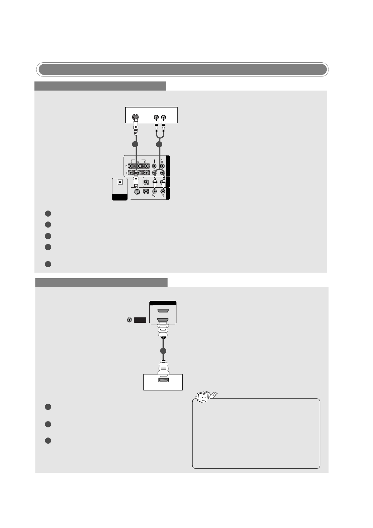
DVD Setup
When connecting with a S-Video cable
HDMI / DVI IN
ANTENNA/
CABLE IN
VIDEOVIDEO
AUDIOAUDIO
VIDEOVIDEO
AUDIOAUDIO
MONO
( )
S-VIDEOS-VIDEO
AV IN 1V IN 1
AV OUTV OUT
COMPONENTCOMPONENT IN IN
DIGITDIGITALAL AUDIO AUDIO
OUTOUT
OPTICALPTICAL
VIDEO
AUDIO
COMPONENT IN
S-VIDEO
(R) AUDIO (L)
DVD
1
1
2
2
3
4
5
Connect the S-VIDEO output of the DVD to the S-VIDEO input on the set.
Connect the audio outputs of the DVD to the AUDIO input jacks on the set.
Turn on the DVD player, insert a DVD.
Select AV1 input source with using the INPUT button on the remote control.
- If connected to AV I N 2 , select AV 2 input source.
Refer to the DVD player's manual for operating instructions.
When connecting with a HDMI cable
1
2
3
Connect the HDMI output of the DVD to the HDMI
IN 1(DVI) or 2 jack on the set.
Select HDMI1/DVI or HDMI2 input source with
using the INPUT button on the remote control.
Refer to the DVD player's manual for operating
instructions.
ANTENNA/ANTENNA/
CABLE INCABLE IN
HDMI-DVD OUTPUT
HDMI IN HDMI IN
1(DVI)
2
DVD
1
• TV can receive the video and audio signal
simultaneously with using a HDMI cable.
• If the DVD supports Auto HDMI function, the
DVD output resolution will be automatically
set to 1280x720p.
• If the DVD does not support Auto HDMI, you
need to set the output resolution appropriately. To get the best picture quality, adjust the
output resolution of the DVD to 1280x720p.
 Loading...