

lg 42PC3DV-UD, 50PC3D-UD, 42PC3D-UD, 32LC2D, 32LC2DC OWNER’S MANUAL
...
Please read this manual carefully before operating your set.
Retain it for future reference.
Record model number and serial number of the set.
See the label attached on the back cover and quote
this information to your dealer
when you require service.
ENERGYSTAR is a set of power-saving
guidelines issued by the U.S.
Environmental Protection Agency(EPA).
As an ENERGY STAR
Partner LGE U. S. A.,Inc.
has determined that this
product meets the ENERGY STAR guidelines for
energy efficiency.
P/NO : 38289U0527B (0605-REV05)
Printed in Korea
OWNER’S MANUAL
LCD TV
MODELS: 32LC2D
32LC2DC
37LC2D
42LC2D
PLASMA TV
MODELS: 42PC3D 42PC1DVH
42PC3DC 42PC3DH
42PC3DV 42PC3DVA
50PC3D 50PC3DH
Internet Home Page : http://www.lge.com
http://www.lg.ca
2
Warning
WARNING:
TO REDUCE THE RISK OF ELECTRIC SHOCK DO NOT REMOVE COVER (OR BACK). NO USER
SERVICEABLE PARTS INSIDE. REFER TO QUALIFIED SERVICE PERSONNEL.
The lightning flash with arrowhead symbol, within an equilateral triangle, is intended to alert the user to
the presence of uninsulated “dangerous voltage” within the product’s enclosure that may be of sufficient magnitude to constitute a risk of electric shock to persons.
The exclamation point within an equilateral triangle is intended to alert the user to the presence of
important operating and maintenance (servicing) instructions in the literature accompanying the appliance.
NOTE TO CABLE/TV INSTALLER:
This reminder is provided to call the CATV system installer’s attention to Article 820-40 of the National Electric
Code (U.S.A.). The code provides guidelines for proper grounding and, in particular, specifies that the cable
ground shall be connected to the grounding system of the building, as close to the point of the cable entry as practical.
REGULATORY INFORMATION
This equipment has been tested and found to comply with the limits for a Class B digital device, pursuant to Part
15 of the FCC Rules. These limits are designed to provide reasonable protection against harmful interference in
a residential installation. This equipment generates, uses and can radiate radio frequency energy and, if not
installed and used in accordance with the instructions, may cause harmful interference to radio communications.
However, there is no guarantee that interference will not occur in a particular installation. If this equipment does
cause harmful interference to radio or television reception, which can be determined by turning the equipment off
and on, the user is encouraged to try to correct the interference by one or more of the following measures:
- Reorient or relocate the receiving antenna.
- Increase the separation between the equipment and receiver.
- Connect the equipment into an outlet on a circuit different from that to which the receiver is connected.
- Consult the dealer or an experienced radio/TV technician for help.
Any changes or modifications not expressly approved by the party responsible for compliance could void the
user’s authority to operate the equipment.
CAUTION:
Do not attempt to modify this product in any way without written authorization from LG Electronics Corporation.
Unauthorized modification could void the user’s authority to operate this product.
U.S.A. only -----------------------------------------------
COMPLIANCE:
The responsible party for this product’s compliance is:
LG Electronics U.S.A., Inc.
1000 Sylvan Avenue, Englewood Cliffs, NJ 07632
Phone: 1-800-243-0000
http://www.lgusa.com
---------------------------------------------------------------
CAUTION
RISK OF ELECTRIC SHOCK
DO NOT OPEN
W
W
arning
arning
3
Safety Instructions
WARNING :
To Reduce The Risk Of Fire Or Electric Shock, Do Not Expose This Apparatus To Rain Or Moisture.
Apparatus shall not be exposed to dripping or splashing and no objects filled with liquids, such as vases, shall be placed on the
apparatus.
IMPORTANT SAFETY INSTRUCTIONS
1. Read these instructions.
2. Keep these instructions.
3. Heed all warnings.
4. Follow all instructions.
5. Do not use this apparatus near water.
6. Clean only with a dry cloth.
7. Do not block any of the ventilation openings. Install in
accordance with the manufacturer’s instructions.
8. Do not install near any heat sources such as radiators,
heat registers, stoves, or other apparatus (including
amplifiers) that produce heat.
9. Do not defeat the safety purpose of the polarized or
grounding type plug. A polarized plug has two blades
with one wider than the other. A grounding type plug has
two blades and a third grounding prong. The wide blade
or the third prong is provided for your safety. When the
provided plug does not fit into your outlet, consult an
electrician for replacement of the obsolete outlet.
10. Protect the power cord from being walked on or
pinched particularly at plugs, convenience receptacles, and the point where they exit from the apparatus.
11. Only use the attachments / accessories specified by
the manufacturer.
Safety Instructions
Safety Instructions
O
w
n
e
r's
M
a
n
u
a
l
4
Safety Instructions
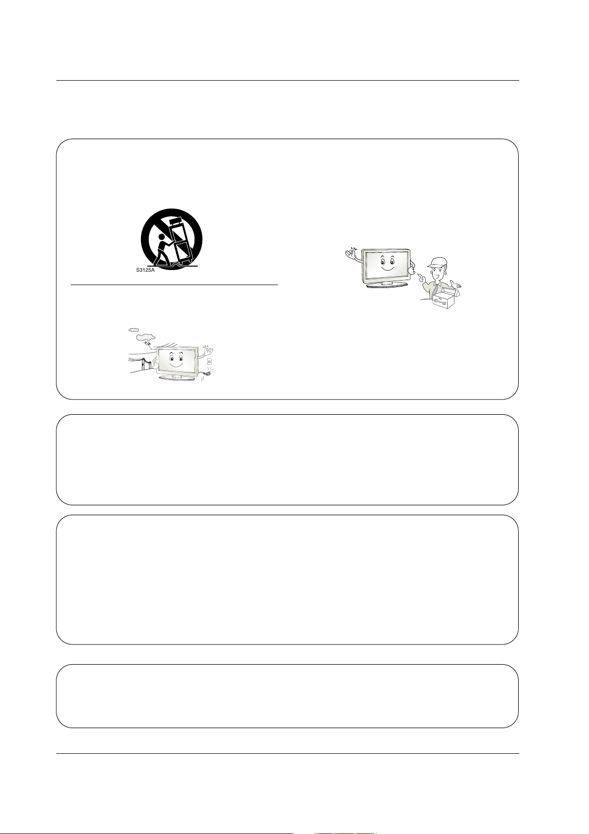
12. Use only with a cart, stand, tripod, bracket, or table
specified by the manufacturer, or sold with the apparatus. When a cart is used, use caution when moving
the cart / apparatus combination to avoid injury from
tip-over.
13. Unplug this apparatus during lightning storms or when
unused for long periods of time.
14. Refer all servicing to qualified service personnel.
Servicing is required when the apparatus has been
damaged in any way, such as power supply cord or
plug is damaged, liquid has been spilled or objects
have fallen into the apparatus, the apparatus has been
exposed to rain or moisture, does not operate normally, or has been dropped.
On Disposal
a. The fluorescent lamp used in this product contains a small amount of mercury.
b. Do not dispose of this product with general household waste.
Disposal of this product must be carried out in accordance to the regulations of your local authority.
Note
- If the TV feels cold to the touch, there may be a small “flicker” when when it is turned on. This is normal, there is nothing wrong with TV.
- Some minute dot defects may be visible on the screen, appearing as tiny red, green, or blue spots. However, they have
no adverse effect on the monitor's performance.
- Avoid touching the LCD screen or holding your finger(s) against it for long periods of time. Doing so may produce some
temporary distortion effects on the screen.
CAUTION concerning the Power Cord
Most appliances recommend they be placed upon a dedicated circuit; that is, a single outlet circuit which powers only that
appliance and has no additional outlets or branch circuits. Check the specification page of this owner's manual to be certain.
Do not overload wall outlets. Overloaded wall outlets, loose or damaged wall outlets, extension cords, frayed power cords,
or damaged or cracked wire insulation are dangerous. Any of these conditions could result in electric shock or fire.
Periodically examine the cord of your appliance, and if its appearance indicates damage or deterioration, unplug it, discontinue use of the appliance, and have the cord replaced with an exact replacement part by an authorized servicer.
Protect the power cord from physical or mechanical abuse, such as being twisted, kinked, pinched, closed in a door, or
walked upon. Pay particular attention to plugs, wall outlets, and the point where the cord exits the appliance.
5
Contents
Contents
Contents
Introduction
Installation
Operation
32 Turning on the TV
32 Volume Adjustment
32 Channel Selection
32 On Screen Menus Language Selection
33 On Screen Menus Selection and Adjustment
34 EZ Scan (Channel Search)
34 Manual Scan
35 Channel Edit
36 DTV Signal Strength
36 Input Source
37 Input Label
38 EZ Picture
38 APM (Adaptive Picture Mode)
39 Manual Picture Control (EZ Picture-Custom option)
39 Color Temperature Control
39 Video Reset
40 Audio Language
40 EZ SoundRite
41 EZ Sound
41 Manual Sound Control (EZ Sound-Custom option)
42 Stereo/SAP Broadcasts Setup
42 Front Surround
43 TV Speakers On/Off Setup
43 BBE
2 Warnings
3~4 Safety Instructions
7 Accessories
8 Controls (Model Name: 32/37/42LC2D**)
8 Swivel Stand (42LC2D** only)
9 Connection Options (Model Name: 32/37/42LC2D**)
10 Controls (Model Name: 42PC1D**/42PC3D**/50PC3D**)
11 Connection Options (Model Name: 42PC1D**/42PC3D**/50PC3D**)
12~16 Remote Control Key Functions
17 Various Installation
18~20 Basic Connection
21 Antenna or Cable Connection
22~23 VCR Setup
23 External AV Source Setup
24~25 DVD Setup
26~27 HDSTB Setup
28 Monitor Out Setup
28 Digital Audio Output
29~31 PC Setup
Setup Menu
Options
Video Menu
Options
Audio Menu
Options
Basic operation
External
Equipment
Connections
6
Contents
Reference
44 Auto Clock Setup
44 Manual Clock Setup
45 On/Off Timer Setup
45 Sleep Timer
46 Auto Off
47 Aspect Ratio Control
48 Cinema 3:2 Mode Setup
48 Caption
49 Caption/Text
50 Caption Option
50 Low Power (42PC1D**/42PC3D**/50PC3D** only)
51 ISM (Image Sticking Minimization) Method (42PC1D**/42PC3D**/50PC3D** only)
52~53 Parental Lock Setup
54~59 External Control Device Setup
60~61 IR Codes
62 Programming the Remote
63~64 Programming Codes
65~66 Troubleshooting Checklist
66 Maintenance
67~68 Product Specifications
Option Menu
Features
Lock Menu Options
Operation
Time Menu
Options
7
Introduction
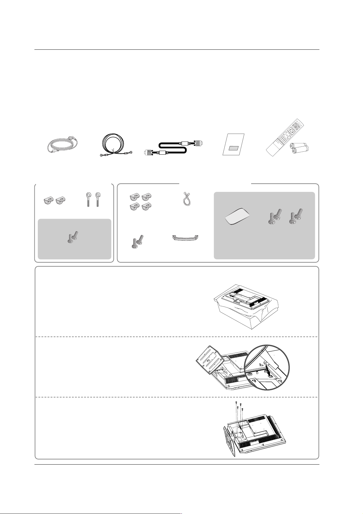
Accessories
Accessories
Introduction
Introduction
Owner’s Manual
75Ω Round Cable
Power Cord
Ensure that the following accessories are included with your TV. If any accessory is missing, please contact the
dealer from where you purchased the product.
1.5V
1.5V
VOL
FLASHBK
CH
1 2 3
456
78
0
9
APM
ADJUST
SAP
EZ SOUND
EZ PIC
FREEZE
D
AY
-
GUID
M
EN
U
MUTE
PAGE
PAGE
FAV
EXIT
TIM
ER
C
C
INFO
ENTER
VOL
CH
PO
WER
1 2 3
456
78
0
9
M
ENU
MUTE
FAV
DA
Y
-
GUIDE
DA
Y
+
R
ATIO
VCR
TV
D
VD
ENTER
APM
ADJUST
SAP
EZ SOUND
EZ PIC
FREEZE
FLASHBK
PAGE
PAGE
EXIT
TIMER
C
C
INFO
AU
D
IO
CA
BL
E
STB
MOD
E
TV INPUT
IN
P
UT
Remote Control /
Batteries
D-sub 15 pin cable
2-eye-bolts
2-TV brackets
2-Wall brackets
2-TV Bracket Bolts
For 32/37/42LC2D**
For 42PC1D**, 42PC3D**, 50PC3D**
Carefully place the product screen side down on a
cushioned surface that will protect product and
screen from damage.
1
Place the hook of the stand in the back of the
product as shown.
2
Install the 4 bolts provided securely, in the back of the
product.
3
Stand Installation for 32LC2D**
Twister Holder
Arrange the wires
with the twister holder.
4-bolts for stand
assembly
See below for detail
information.
32LC2D** only42LC2D** only
Cable
Management
(Refer p.18)
Polishing Cloth
Polish the TV with
the cloth.
42PC1D**, 42PC3D** only
2-Wall brackets
2-bolts
(Refer p.19)
8
Introduction
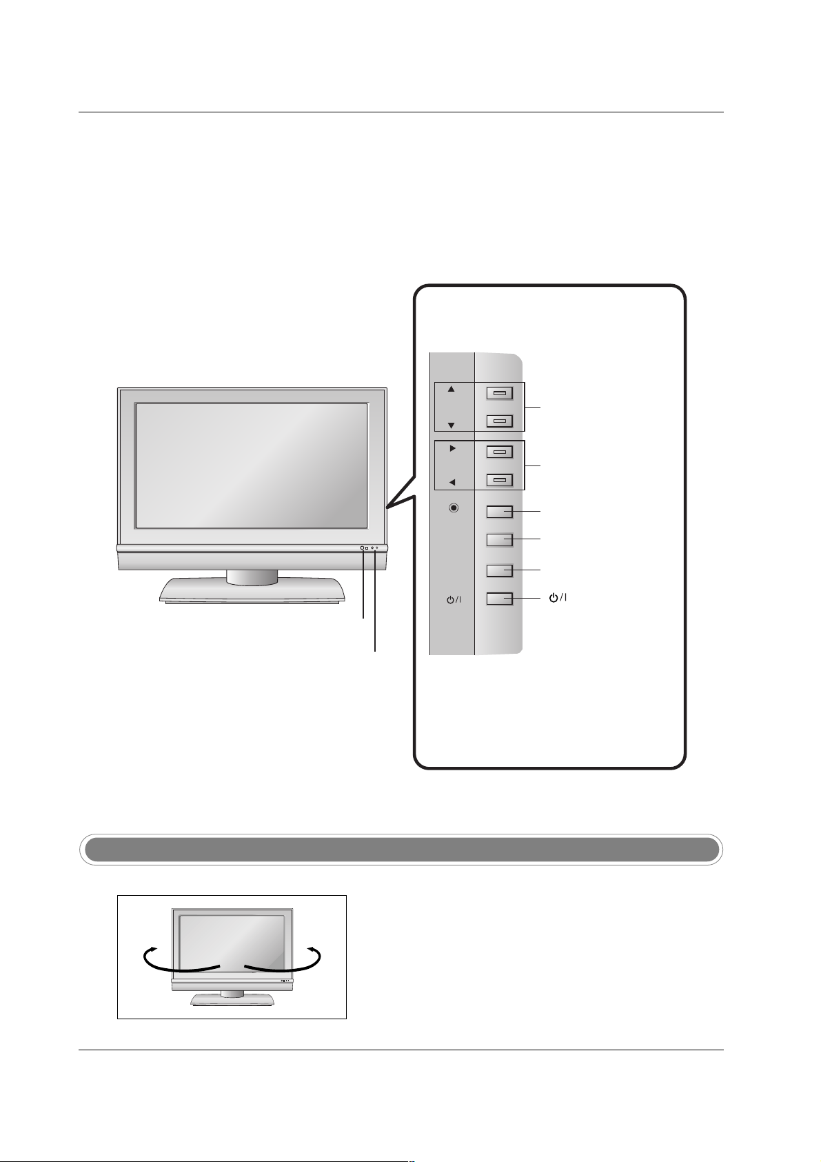
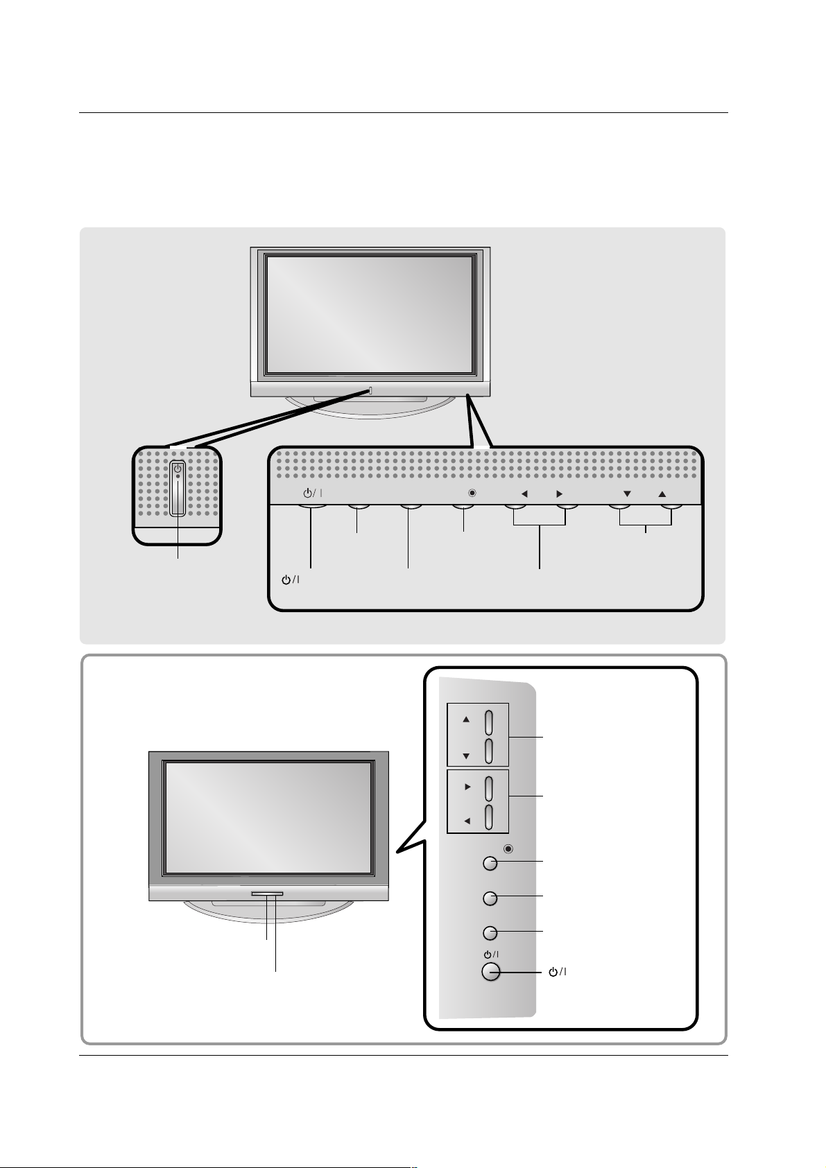
Controls
Controls
(Model Name: 32/37/42LC2D**)
(Model Name: 32/37/42LC2D**)
- This is a simplified representation of front panel.
- Here shown may be somewhat different from your TV.
CH
VOL
ENTER
MENU
INPUT
CHANNEL (D, E)
Buttons
VOLUME (F,G)
Buttons
ENTER Button
MENU Button
INPUT Button
(Power) Button
Remote Control Sensor
Power/Standby Indicator
• illuminates red in standby mode.
• illuminates green when the set is
switched on.
- The TV can be conveniently swivelled on its stand 30°
to the left or right to provide the optimum viewing angle.
Swivel Stand (42LC2D** only)
R
30° 30°
CH
VOL
ENTER
R
MENU
INPUT
9
Introduction
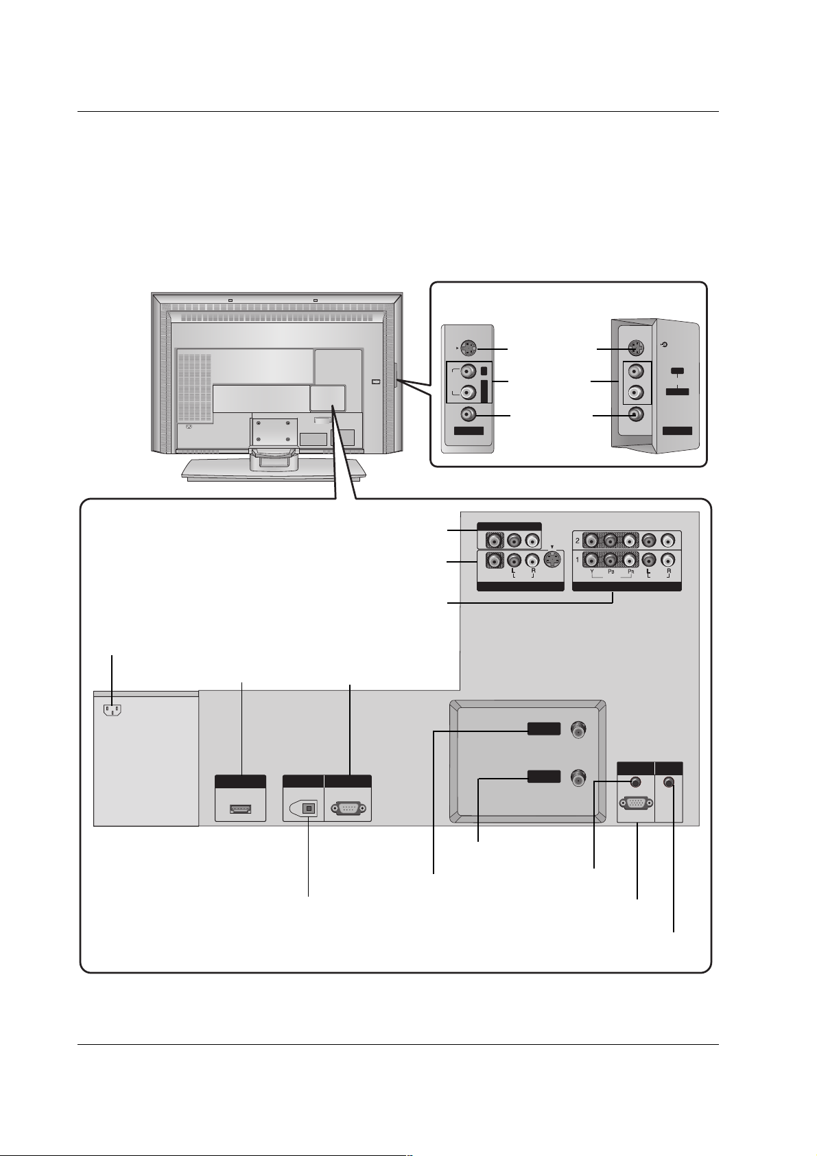
Connection Options (Model Name: 32/37/42LC2D**)
Connection Options (Model Name: 32/37/42LC2D**)
AV IN 2
MONO
AUDIO
S-VIDEO
VIDEO
L/
MONO
AUDIO
S-VIDEO
VIDEO
AV IN 2
HDMI/DVI IN
DIGITAL AUDIO
OUT
PTICAL
RS-232C IN
(CONTROL
SERVICE)
VIDEO
AUDIO
VIDEO
AUDIO
COMPONENT IN
S-VIDEO
AV IN 1
AV OUT
ANTENNA
IN
CABLE
IN
RGB (PC
DTV)
RGB IN
AUDIO (RGB/DVI)
REMOTE
CONTROL IN
AUDIO Input
S-VIDEO Input
37/42LC2D**
32LC2D**
VIDEO Input
DIGITALAUDIO OUT
OPTICAL
AV OUT
AV IN1
COMPONENT IN 1/2
HDMI / DVI IN
ANTENNA IN
CABLE IN
AUDIO (RGB/DVI)
RGB (PC/DTV)
AC IN
RS-232C INPUT
(CONTROL&SERVICE)
REMOTE CONTROL Port
- Here shown may be somewhat different from your TV.
AC IN
AC IN
HDMI/DVI IN
OUT
RS-232C IN
(CONTROL
&
SERVICE)
DIGITAL AUDIO
OPTICAL
S-VIDEO
R
AUDIO
MONO
L/
VIDEO
AV IN 2
VIDEO
AV OUT
(
)
MONO
S-VIDEO
AUDIO
AV IN 1
ANTENNA
IN
CABLE
IN
VIDEO
COMPONENT IN
AUDIO
RGB IN
AUDIO (RGB/DVI)
RGB (PC
/
DTV)
S-VIDEO
R
AUDIO
L/L/MONO
VIDEO
AV IN 2
REMOTE
CONTROL IN
10
Introduction
Controls
Controls
(Model Name: 42PC1D**/42PC3D**/50PC3D**)
(Model Name: 42PC1D**/42PC3D**/50PC3D**)
- This is a simplified representation of front panel.
- Here shown may be somewhat different from your TV.
CH
VOL
ENTER
MENU
INPUT
CH
VOL
ENTER
MENU
INPUT
CHANNEL (D, E)
Buttons
VOLUME (
F,G)
Buttons
MENU Button
ENTER Button
INPUT Button
(Power)
Button
Power/Standby Indicator
• illuminates red in standby
mode.
• illuminates green when the set
is switched on.
CHANNEL (D, E)
Buttons
VOLUME (F,G)
Buttons
ENTER Button
MENU Button
INPUT Button
Remote Control Sensor
Power/Standby Indicator
• illuminates red in standby mode.
• illuminates green when the set is switched on.
(Power) Button
42PC1D**
42PC3D**/50PC3D**
11
Introduction
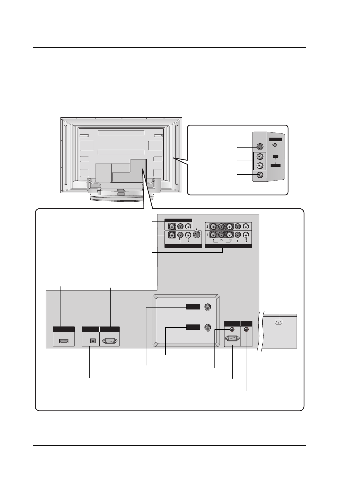
Connection Options
Connection Options
(Model Name: 42PC1D**/42PC3D**/50PC3D**)
(Model Name: 42PC1D**/42PC3D**/50PC3D**)
AV IN 2
MONO
AUDIO
S-VIDEO
VIDEO
HDMI/DVI IN
DIGITAL AUDIO
OUT
PTICAL
RS-232C IN
(CONTROL
SERVICE)
RGB (PC
DTV)
RGB IN
AUDIO (RGB/DVI)
VIDEO
AUDIO
VIDEO
AUDIO
COMPONENT IN
S-VIDEO
AV IN 1
AV OUT
ANTENNA
IN
CABLE
IN
REMOTE
CONTROL IN
- Here shown may be somewhat different from your TV.
AUDIO Input
S-VIDEO Input
VIDEO Input
DIGITAL AUDIO OUT
OPTICAL
AV OUT
AV I N 1
COMPONENT IN 1/2
HDMI/DVI IN
ANTENNA IN
CABLE IN
AUDIO (RGB/DVI)
RGB (PC/DTV)
AC IN
RS-232C INPUT
(CONTROL&SERVICE)
REMOTE CONTROL Port
VIDEO
AV OUT
AV IN 1
(
)
MONO
S-VIDEO
AUDIO
VIDEO
COMPONENT IN
AUDIO
AV IN 2
S-VIDEO
R
AUDIO
L/L/MONO
VIDEO
HDMI/DVI IN
OUT
RS-232C IN
(CONTROL
&
SERVICE)
DIGITAL AUDIO
OPTICAL
ANTENNA
IN
CABLE
IN
RGB IN
AUDIO (RGB/DVI)
RGB (PC
/
DTV)
REMOTE
CONTROL IN
AC IN
12
Introduction
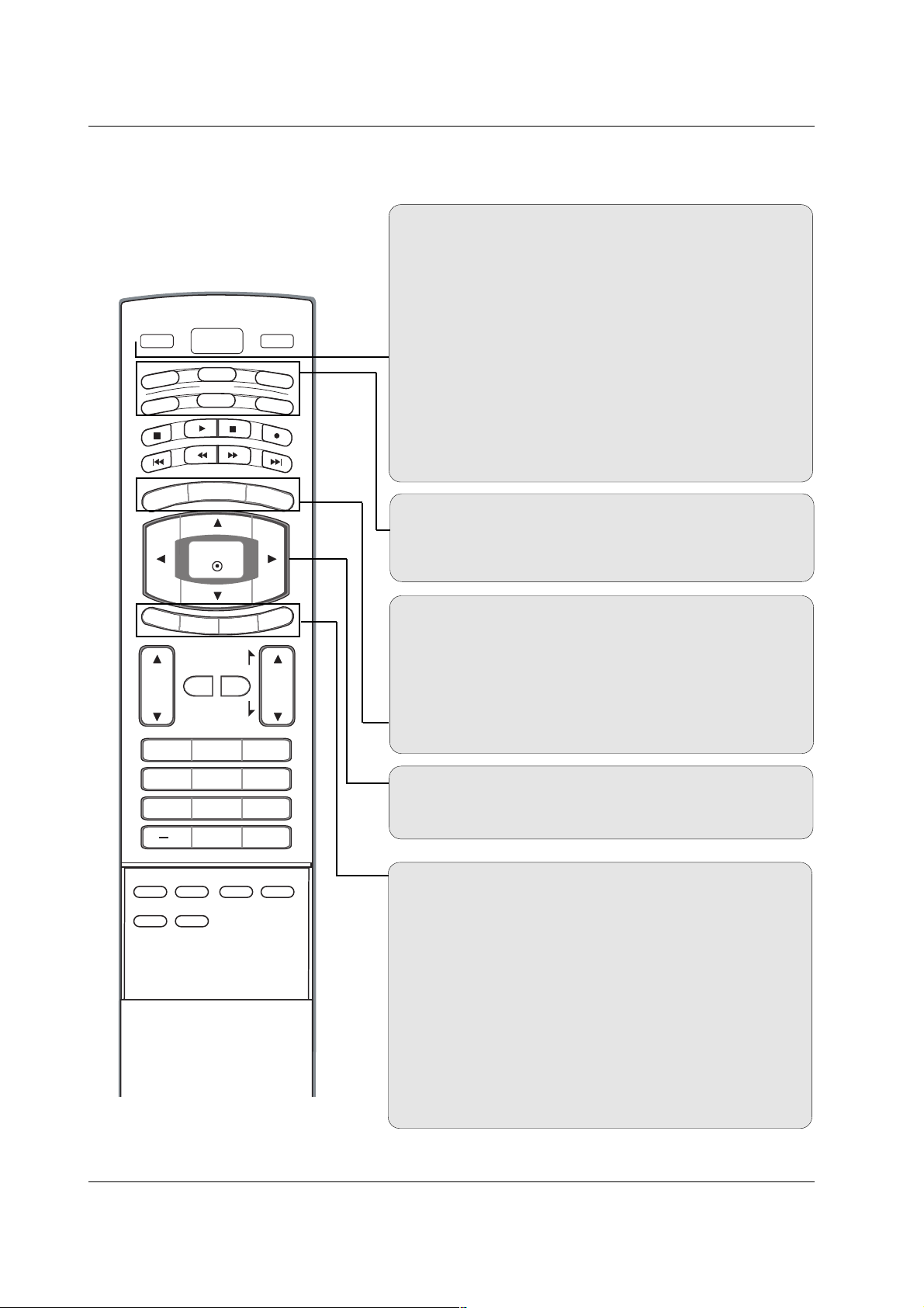
Remote Control Key Functions
Remote Control Key Functions
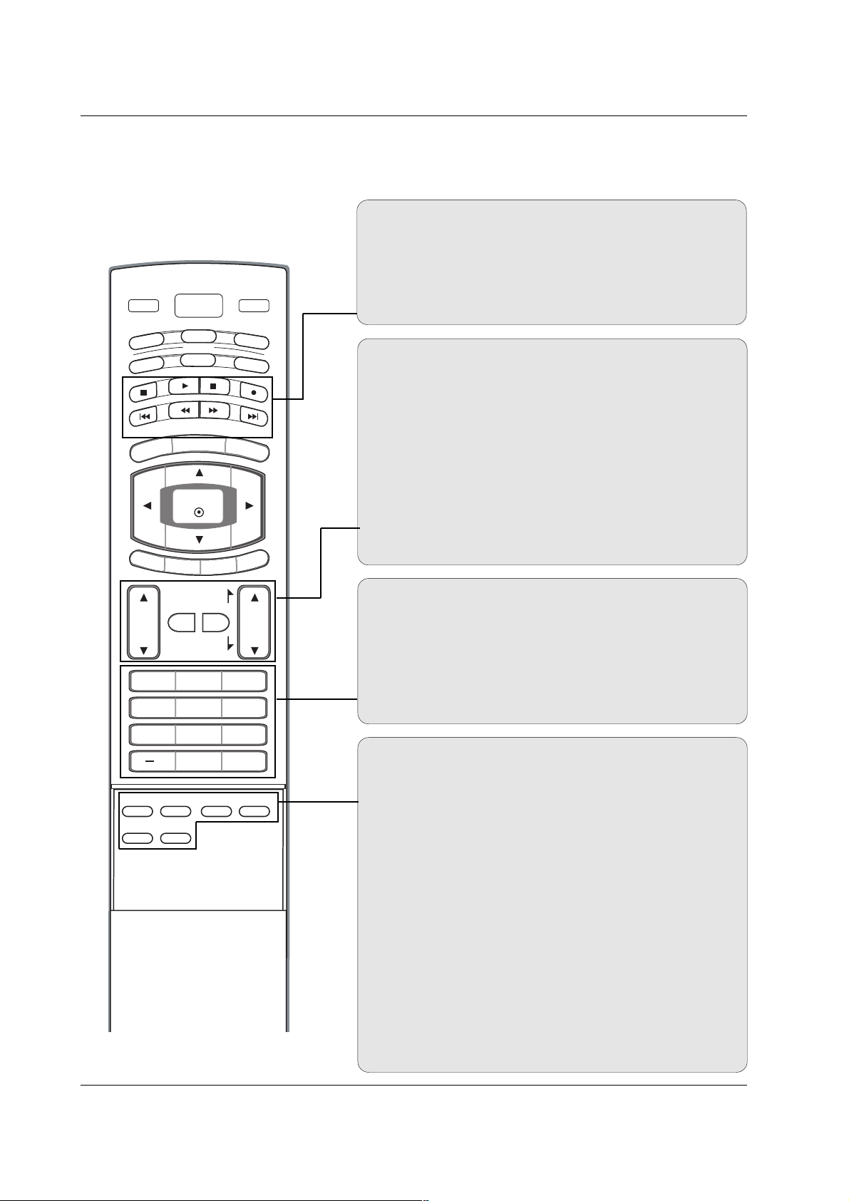
POWER
Turns your TV or any other programmed equipment on or
off, depending on mode.
VOL
CH
POWER
1 2 3
4 5 6
7809
MENU
MUTE
FAV
DAY
-
GUIDE
DAY+
RATIO
VCR
TV
DVD
ENTER
APM
ADJUST
SAP
EZ SOUND
EZ PIC
FREEZE
FLASHBK
PAG E
PAG E
EXIT
TIMER
CC
INFO
AUDI O
CABLE
STB
MODE
TV INPUT
INPUT
TV INPUT
Rotates the input mode between Antenna and Cable. In AV12, Component 1-2, RGB-DTV (or RGB-PC), and HDMI/DVI
input sources, screen returns to the last TV channel.
MODE
Selects the remote operating mode: TV, DVD, VCR, AUDIO,
CABLE, or STB. Select a mode other than TV, for the remote
to operate an external device.
INPUT (Refer to p.14)
External input modes rotate in regular sequence: Antenna,
Cable, AV1-2, Component 1-2, RGB-DTV (or RGB-PC),
HDMI/DVI). (AV1, AV2,Component 1-2 input sources are linked
automatically, Only if these are connected)
EXIT
Clears all on-screen displays and returns to TV viewing from
any menu.
TIMER (Refer to p.45)
Lets you select the amount of time before your TV turns
itself off automatically.
CC (Refer to p.49)
Select a closed caption: Off, CC1~4, Text1~4.
MENU
Brings up the main menu to the screen.
GUIDE (Refer to p.16)
Shows program schedule.
RATIO (Refer to p.47)
Changes the aspect ratio.
THUMBSTICK (Up/Down/Left/Right/ENTER)
Allows you to navigate the on-screen menus and adjust the
system settings to your preference.
INFO (Refer to p.15)
When you watch the TV, information displays on top of the
screen. Not available in Component 1-2, RGB and HDMI/DVI
mode.
13
Introduction
EZ PIC (Refer to p.38)
Selects a factory preset picture mode depending on the viewing environment.
EZ SOUND (Refer to p.41)
Selects the sound appropriate for the program's character.
SAP (Refer to p.42)
Selects MTS sound: Mono, Stereo, and SAP in analog mode.
Change the audio language in DTV mode.
FREEZE
Freezes the currently-viewed picture.
ADJUST (Refer to p.31)
Adjusts screen position, size, and phase in PC mode.
APM (Refer to p.38)
Concurrently, compare with the Daylight, Normal, Night Time
and Custom on the screen.
FAV
Use to scroll the Favorite channels.
MUTE
Switches the sound on or off.
CHANNEL UP/DOWN
Selects available channels found with EZ scan and Manual scan.
PAGE UP/DOWN
Moves from one full set of screen information to the next one.
VOLUME UP/DOWN
Increases/decreases the sound level.
VOL
CH
POWER
1 2 3
4 5 6
7809
MENU
MUTE
FAV
DAY
-
GUIDE
DAY+
RATIO
VCR
TV
DVD
ENTER
APM
ADJUST
SAP
EZ SOUND
EZ PIC
FREEZE
FLASHBK
PAG E
PAG E
EXIT
TIMER
CC
INFO
AUDI O
CABLE
STB
MODE
TV INPUT
INPUT
— (DASH)
Used to enter a program number for multiple program channels such as 2-1, 2-2,etc.
NUMBER BUTTONS
FLASHBK
Returns to the last channel viewed.
VCR/DVD/DVHS/Camcorder BUTTONS
Control some video cassette recorders or DVD players
("RECORD" button is not available for DVD player).
DAY + / DAY-
Moves forward or backward in 24 hour increments.
14
Introduction
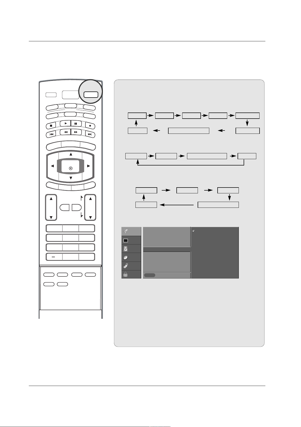
1. When every external equipment is connected:
2. When any external equipment is not connected:
Auto Link
Auto Link
Antenna AV1 AV2Cable Component1
HDMI/DVI Component2RGB-DTV (or RGB-PC)
3. When some External Equipment is connected:
(ex: When connected to AV IN1)
RGB-DTV (or RGB-PC)
AV1
HDMI/DVI
Antenna Cable
Antenna Cable RGB-DTV (or RGB-PC) HDMI/DVI
• You can also select Input Source in the SETUP menu.
• Antenna: Select it when watching the TV/DTV.
•
Cable: Select it when watching the CATV/CADTV.
•
AV 1 , AV 2 : Select it when watching the VCR or external equip-
ment.
• Component 1-2: Select it when using the DVD or the Digital
set-top box depend on connector.
•
RGB-PC / RGB-DTV: Select it when using PC or Digital set-top
box depend on connector.
•
HDMI / DVI: Select it when using DVD, PC or Digital set-top
box depend on connector.
INPUT
Previous
MENU
EZ Scan
Manual Scan
Channel Edit
DTV Signal
Input Source
G
Input Label
Set ID
Antenna
Cable
AV1
AV2
Component1
Component2
RGB-PC
HDMI/DVI
SETUP
VIDEO
AUDIO
TIME
OPTION
LOCK
TV INPUT
TV
AUDI O
DAY
MENU
EXIT
VOL
POWER
DVD
MODE
CABLE
-
GUIDE
ENTER
TIMER
MUTE
1 2 3
4 5 6
7809
EZ SOUND
EZ PIC
ADJUST
APM
CC
PAG E
FAV
PAG E
SAP
INPUT
VCR
STB
DAY+
RATIO
INFO
CH
FLASHBK
FREEZE
15
Introduction
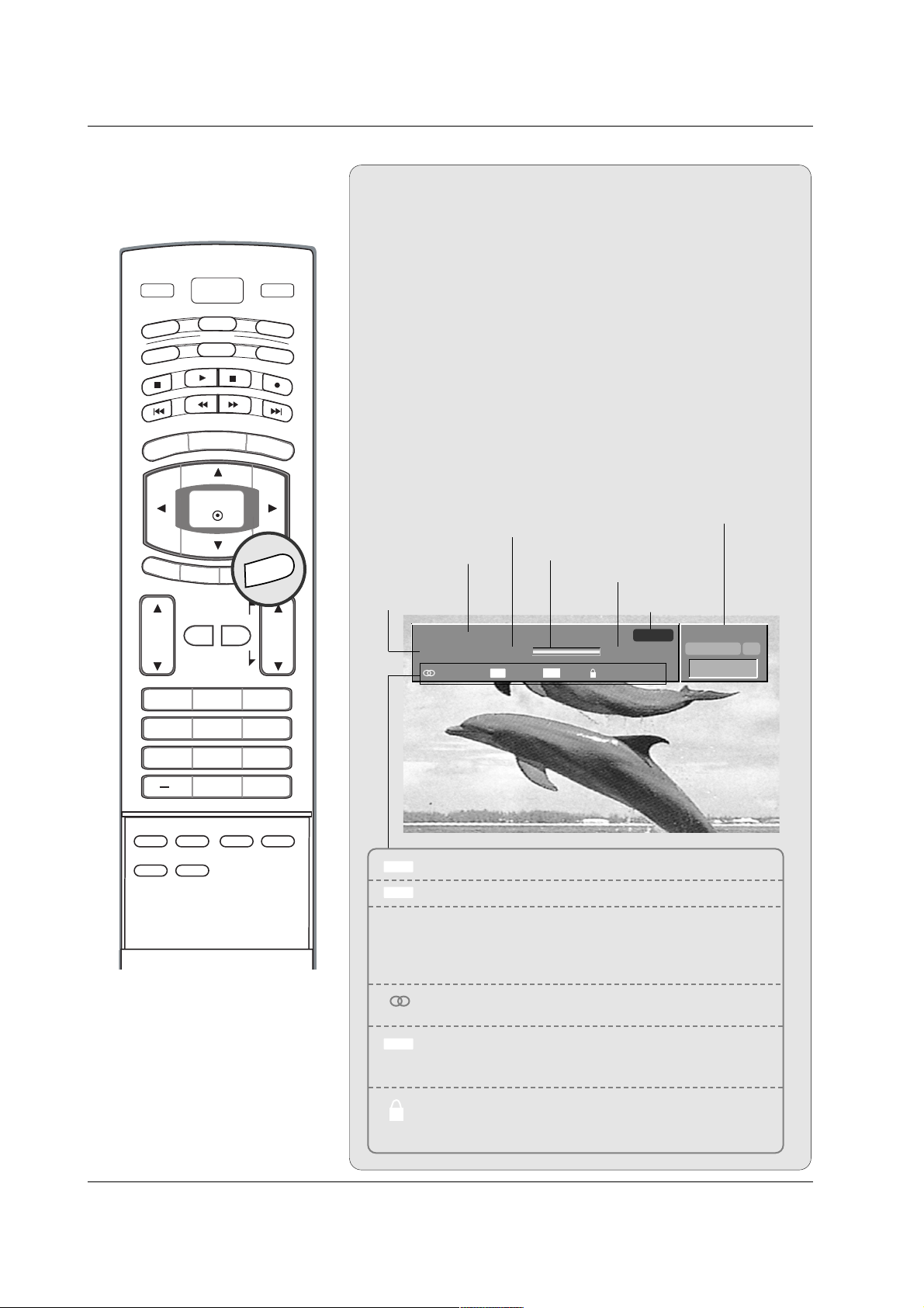
TV INPUT
Brief Info.
Brief Info.
What is Brief Info?
: Brief Info shows the present screen information.
: On Watching with the upper Input signal, press the INFO
button.
How to use?
1. Press the INFO button to show the Brief Info on the screen.
2. Press the INFO button or EXIT button to exit.
- The INFO button does not work in Component1,
Component2, RGB, and HDMI/DVI modes.
This function works in the following mode:
• Watching TV/DTV/CATV/CADTV
• Watching AV1, AV2
Brief Info Title Test Brief Info Title Test Brief Inf..
SAT, Jan 20, 2005 7:00PM
Multilingual
Caption 1080i TV-PG D L S V
6:55AM
DTV 2-1
CC 4:3
Program title
Program start time
Banner information
Program progress bar
Program finish time
Present time
Day of week
Month, Year
The original aspect ratio of the video is 4:3
The original aspect ratio of the video is 16:9 (wide)
The video resolution is 720x480i
The video resolution is 720x480p
The video resolution is 1280x720p
The video resolution is 1920x1080i
Multilingual: The program contains two or more audio
services. Press the SAP button to select wanted Audio.
Caption: The program contains one or more caption services. Press the CC button to select wanted Closed caption.
V-Chip: The program contains V-Chip information. Refer
to the
LOCK menu: A (Age), D (Dialogue), L (Language), S
(Sex), V (Violence), FV (Fantasy Violence)
16 : 9
4 : 3
CC
480i
480p
720p
1080i
ABCDEFGHIJ...
10:40AM
Dolby Digital HD
INFO
TV
AUDI O
-
DAY
MENU
POWER
DVD
MODE
CABLE
GUIDE
ENTER
INPUT
VCR
STB
DAY+
RATIO
EXIT
TIMER
VOL
MUTE
1 2 3
4 5 6
7809
EZ SOUND
EZ PIC
ADJUST
APM
CC
PAG E
FAV
PAG E
SAP
INFO
CH
FLASHBK
FREEZE
16
Introduction
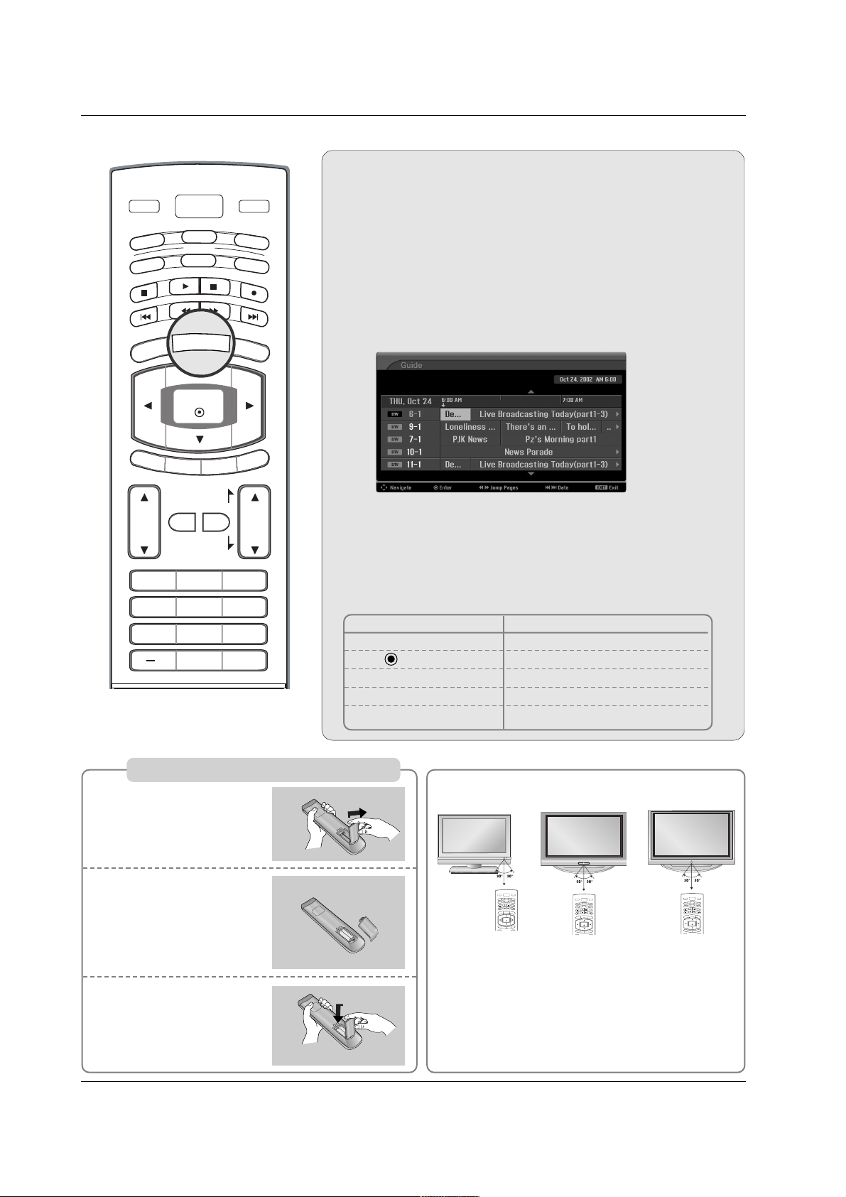
EPG (Electronic Program Guide)
EPG (Electronic Program Guide)
(In DTV mode)
(In DTV mode)
- This system has an Electronic Program Guide (EPG) to help
your navigate through all the possible viewing options.
- The EPG supplies information such as program listings, start
and end times for all available services.
- This function can be used only when the EPG information is
broadcasted by broadcasting companies.
- The EPG displays the program description for next 3 days.
- This function is only supported in DTV mode.
Press the GUIDE button to switch on EPG.
Press the
DD / EE
/
FF / GG
button to select desired program, then
press the ENTER button to display the selected program.
Press the GUIDE or EXIT button again to switch off EPG and
return to TV viewing.
1
2
3
Remote Control Buttons Function
D / E
/
F / G Select the desired program
Change to the selected channel
FF/ GG Jump Page
IFF
/
GGI Change the date
GUIDE/EXIT Switch off EPG
GUIDE
Installing Batteries
Open the battery compartment cover on the
back side.
Insert two batteries in
correct polarity (+ with
+, - with -). Don’t mix
old or used batteries
with new ones.
Close the cover.
* Use a remote control 7 meter distance and 30
degree (left/right) within the receiving unit scope.
* Dispose of used batteries in a recycle bin to prevent
environment.
POWER
MENU
DAY
-
GUIDE
DAY+
RATIO
VCR
TV
DVD
ENTER
EXIT
TIME
R
C
C
INFO
AU
D
IO
CABLE
STB
MODE
TV INPUT
INPUT
POWER
MENU
DAY
-
GUIDE
DAY+
RATIO
VCR
TV
DVD
ENTER
EXIT
TIME
R
C
C
INFO
AU
D
IO
CABLE
STB
MODE
TV INPUT
INPUT
1
2
3
32/37/42LC2D**
42/50PC3D**
POWER
MENU
DAY
-
GUIDE
DAY+
RATIO
VCR
TV
DVD
ENTER
EXIT
TIME
R
C
C
INFO
AU
D
IO
CABLE
STB
MODE
TV INPUT
INPUT
42PC1D**
TV INPUT
POWER
-
DVD
MODE
CABLE
GUIDE
TV
AUDI O
DAY
MENU
ENTER
EXIT
TIMER
VOL
MUTE
1 2 3
4 5 6
7809
CC
PAG E
FAV
PAG E
INPUT
VCR
STB
DAY+
RATIO
INFO
CH
FLASHBK
17
Installation
Installation
Installation
Desktop Pedestal Installation
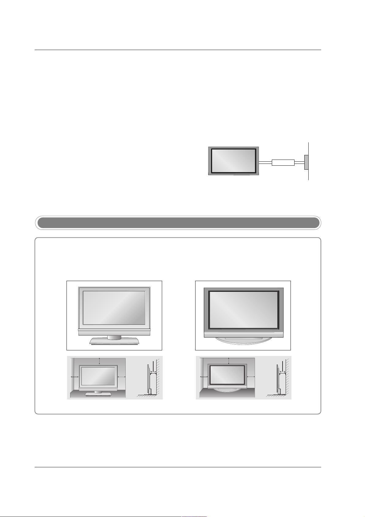
For proper ventilation, allow a clearance of 4" on each side and from the wall.
GROUNDING
Ensure that you connect the earth ground wire to prevent possible electric shock. If grounding methods are not possible,
have a qualified electrician install a separate circuit breaker.
Do not try to ground the unit by connecting it to telephone
wires, lightening rods, or gas pipes.
Power
Supply
Short-circuit
Breaker
• The TV can be installed in various ways such as on a wall, or on a desktop etc.
• The TV is designed to be mounted horizontally.
Various Installation
32/37/42LC2D** 42PC1D**, 42PC3D**, 50PC3D**
4 inches
4 inches
4 inches
4 inches
4 inches
4 inches
4 inches4 inches
18
Installation
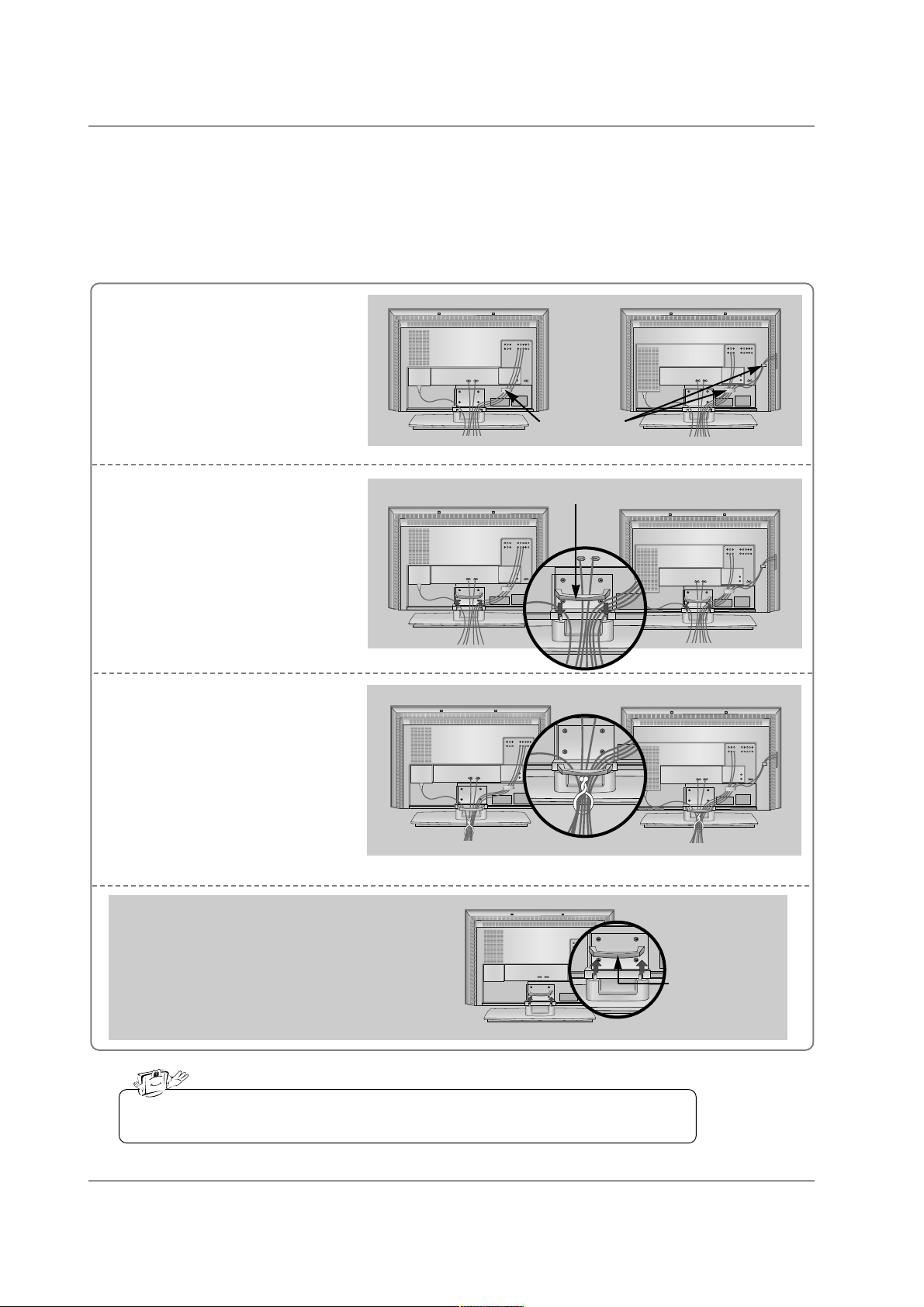
Connect the cables as necessary.
After connecting the cables neatly, arrange the cables to the
Cable Holder.
To connect an additional equipment, see the External equip-
ment Connections section.
Reinstall the CABLE MANAGE-
MENT as shown.
1
2
Bundle the cables using the supplied twister holder.
3
Basic Connection (For 32/37/42LC2D**)
Basic Connection (For 32/37/42LC2D**)
Installation
Installation
32LC2D**
Cable holder
37/42LC2D**
32LC2D**
37/42LC2D**
32LC2D**
37/42LC2D**
Do not hold the CABLE MANAGEMENT when moving the product.
- If the product is dropped, you may be injured or the product may be broken.
How to remove
the CABLE MANAGEMENT
- Hold the CABLE MANAGEMENT with both hands
and pull it upward.
CABLE
MANAGEMENT
CABLE MANAGEMENT
19
Installation
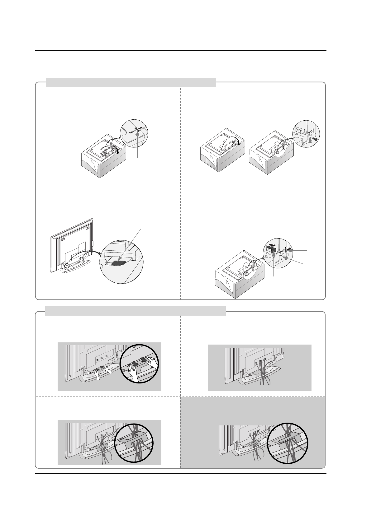
Place the set with the screen facing down on
a cushion or soft cloth as shown.
Before unfolding the stand, please make sure
two locks (A) on the bottom of the stand push
outward.
Pull the stand out as shown.
After unfolding the stand, please insert and
tighten the screws (provided as parts of the
product) in the holes (B) on the bottom of the
stand.
1
2
When connecting cables to the set, Do not
disengage the lock (C).
This may cause the set to fall, causing serious
bodily injury and serious damage to the set.
3
Basic Connection
Basic Connection
(C)
Hold the CABLE MANAGEMENT with both
hands and push it as shown.
Connect the cables as necessary.
To connect an additional equipment, see the
External equipment Connections section.
Reinstall the CABLE MANAGEMENT as
shown.
1
2
3
* Image shown here may be slightly different from
your set.
When closing the stand for storage
- First remove the screws in the holes (B) on the bottom
of the stand. And then pull two Hooks (D) of the stand
bottom and fold the stand into the back of the set.
- After folding, push the two Locks (A) of the stand
bottom outward.
(A)
(B)
(D)
(A)
(B)
How to use stand (For 42PC1D**, 42PC3D**)
How to arrange the cable (For 50PC3D**)
For 42PC1D**, 42PC3D**
Arrange the cable as shown.
20
Installation
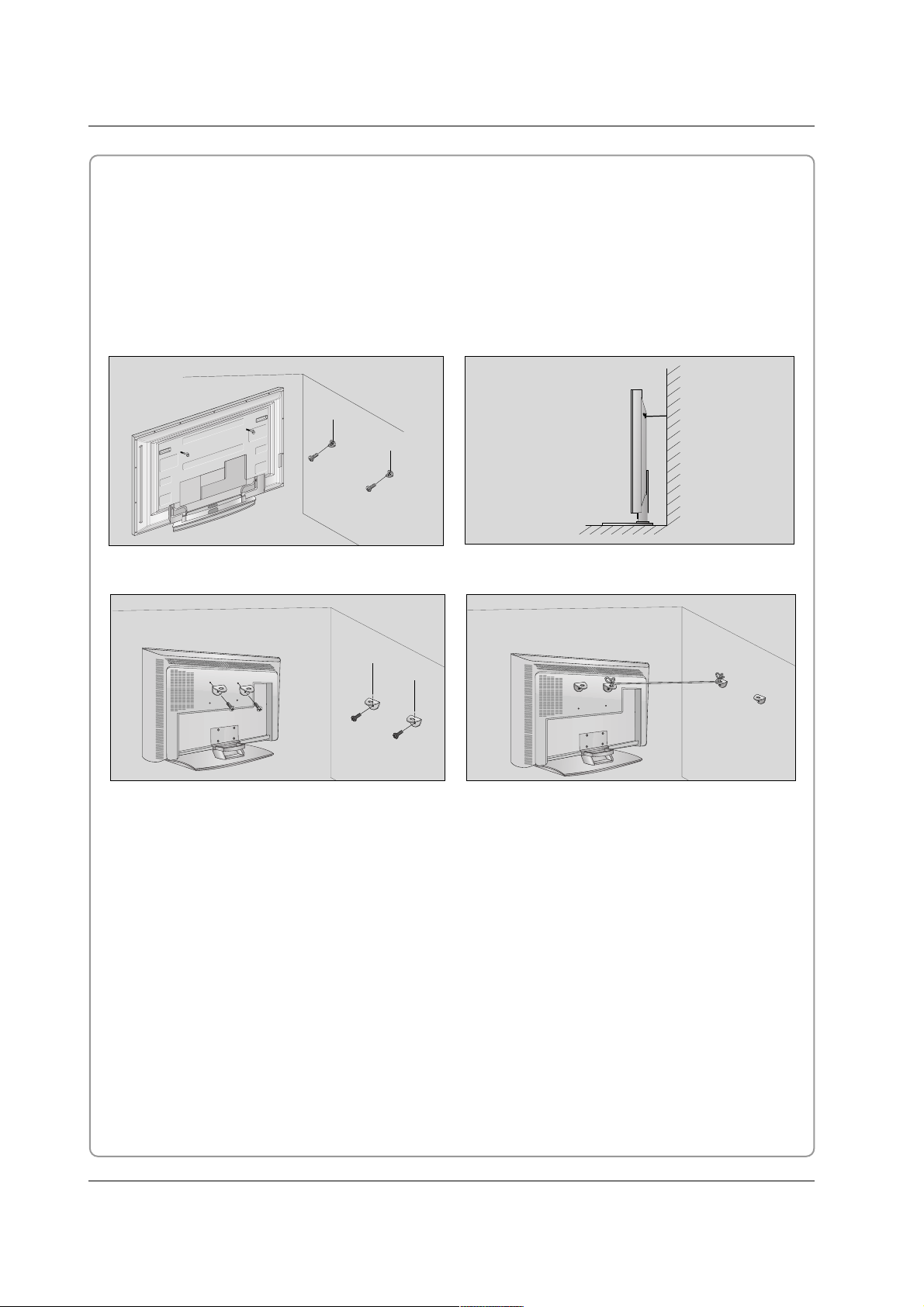
How to join the product assembly to the wall to protect the set tumbling
- Set it up close to the wall so the product doesn’t fall over when it is pushed backwards.
- The instructions shown below is a safer way to set up the product, which is to fix it on the wall so the product doesn’t fall over when it is pulled in the forward direction. It will prevent the product from falling forward and hurting people. It will also prevent the product from damage caused by fall. Please make sure
that children don’t climb on or hang from the product.
42PC1D**/42PC3D**/50PC3D**
Notes
• When moving the product to another place undo the ropes first.
• Use a product holder or a cabinet that is big and strong enough for the size and weight of the product.
• To use the product safely make sure that the height of the bracket that is mounted on the wall is same
as that of the product.
2
2
3
1
1
3
Use the eye-bolts or TV brackets/bolts to fix the product to the wall as shown in the picture.
(If your product has the bolts in the eye-bolts position before inserting the eye-bolts, loosen the bolts.)
* Insert the eye-bolts or TV brackets/bolts and tighten them securely in the upper holes.
Secure the wall brackets with the bolts (not provided as parts of the product, must purchase separately)
on the wall. Match the height of the bracket that is mounted on the wall.
Use a sturdy rope (not provided as parts of the product, must purchase separately) to tie the product.
It is safer to tie the rope so it becomes horizontal between the wall and the product.
1
2
3
32/37/42LC2D**
21
Installation
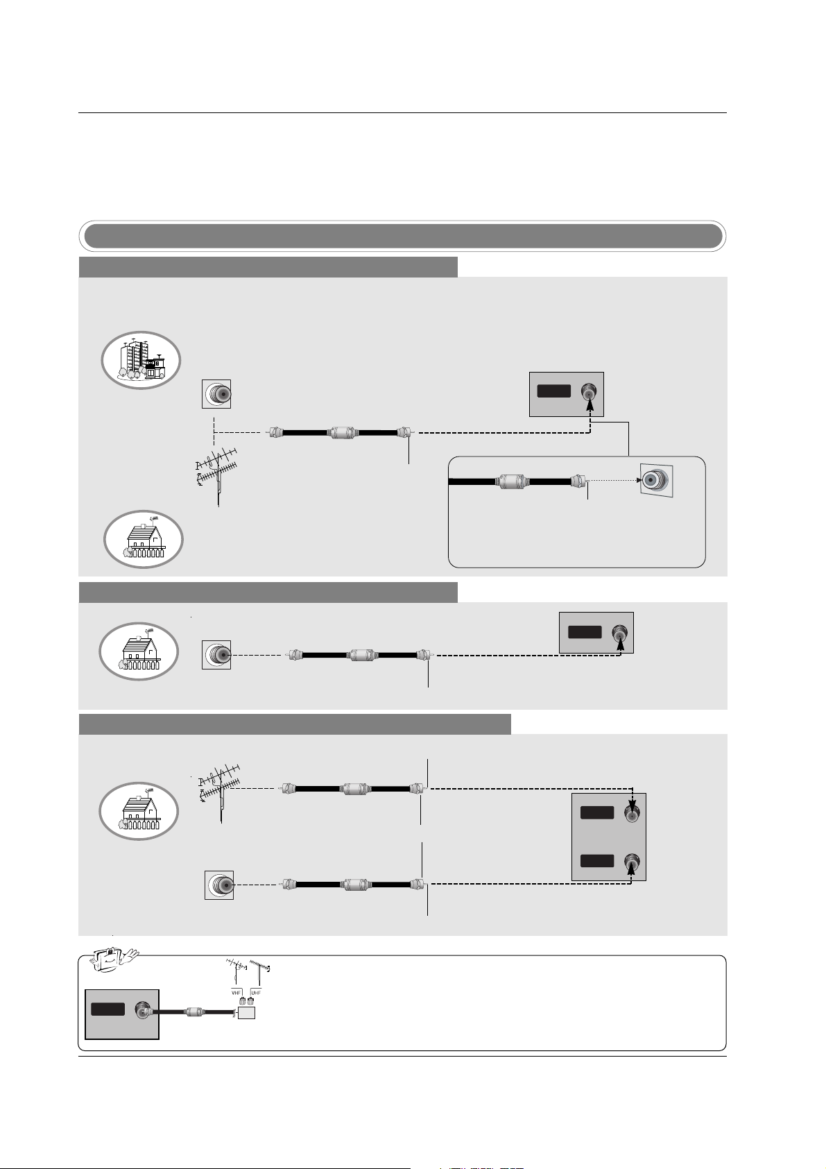
Antenna or Cable Connection
Multi-family Dwellings/Apartments
(Connect to wall antenna socket)
Single-family Dwellings /Houses
(Connect to wall jack for outdoor antenna)
Outdoor Antenna
Wall Antenna Socket
VHF Antenna
UHF Antenna
RF Coaxial Wire (75 ohm)
Turn clockwise to tighten.
AV IN 2
L/MONO
R
AUDIO
S-VIDEO
VIDEO
VIDEO
AUDIO
COMPONENT IN
S-VIDEO
ANTENNAANTENNA
ININ
Bronze Wire
Be careful not to bend the bronze wire when
connecting the antenna.
Analog and Digital TV signals provided on antenna
- Antenna or Cable Service without a Cable Box Connection.
- For optimum picture quality, adjust antenna direction if needed.
Cable TV Wall Jack
RF Coaxial Wire (75 ohm)
Turn clockwise to tighten.
Analog and Digital TV signals provided on cable
Analog and Digital TV signals provided on cable and antenna
Cable TV Wall Jack
RF Coaxial Wire (75 ohm)
Bronze Wire
Bronze Wire
Turn clockwise to tighten.
Antenna
RF Coaxial Wire (75 ohm)
• In a poor signal area to improve picture quality, purchase and install a signal amplifier.
• If the antenna needs to be split for two TV’s, install a “2-Way Signal Splitter”
in the connections.
• If the antenna is not installed properly, contact your dealer for assistance.
AV IN 2
L/MONO
R
AUDIO
S-VIDEO
VIDEO
VIDEO
AUDIO
COMPONENT IN
S-VIDEO
ANTENNAANTENNA
ININ
External Equipment Connections
External Equipment Connections
signal
amplifier
AV IN 2
L/MONO
R
AUDIO
S-VIDEO
VIDEO
VIDEO
AUDIO
COMPONENT IN
S-VIDEO
ANTENNA
IN
CABLECABLE
ININ
RGB IN
AUDIO (RGB/DVI)
REMOTE
CONTROL IN
AV IN 2
L/MONO
R
AUDIO
S-VIDEO
VIDEO
VIDEO
AUDIO
COMPONENT IN
S-VIDEO
ANTENNA
IN
CABLE
IN
RGB IN
AUDIO (RGB/DVI)
REMOTE
CONTROL IN
NOTE: All cables shown are not included with the TV
ANTENNA
CABLE
IN
IN
22
Installation
- To avoid picture noise (interference), leave an adequate distance between the VCR and TV.
- Typically a frozen still picture from a VCR. If the 4:3 picture format is used; the fixed images on the sides
of the screen may remain visible on the screen.
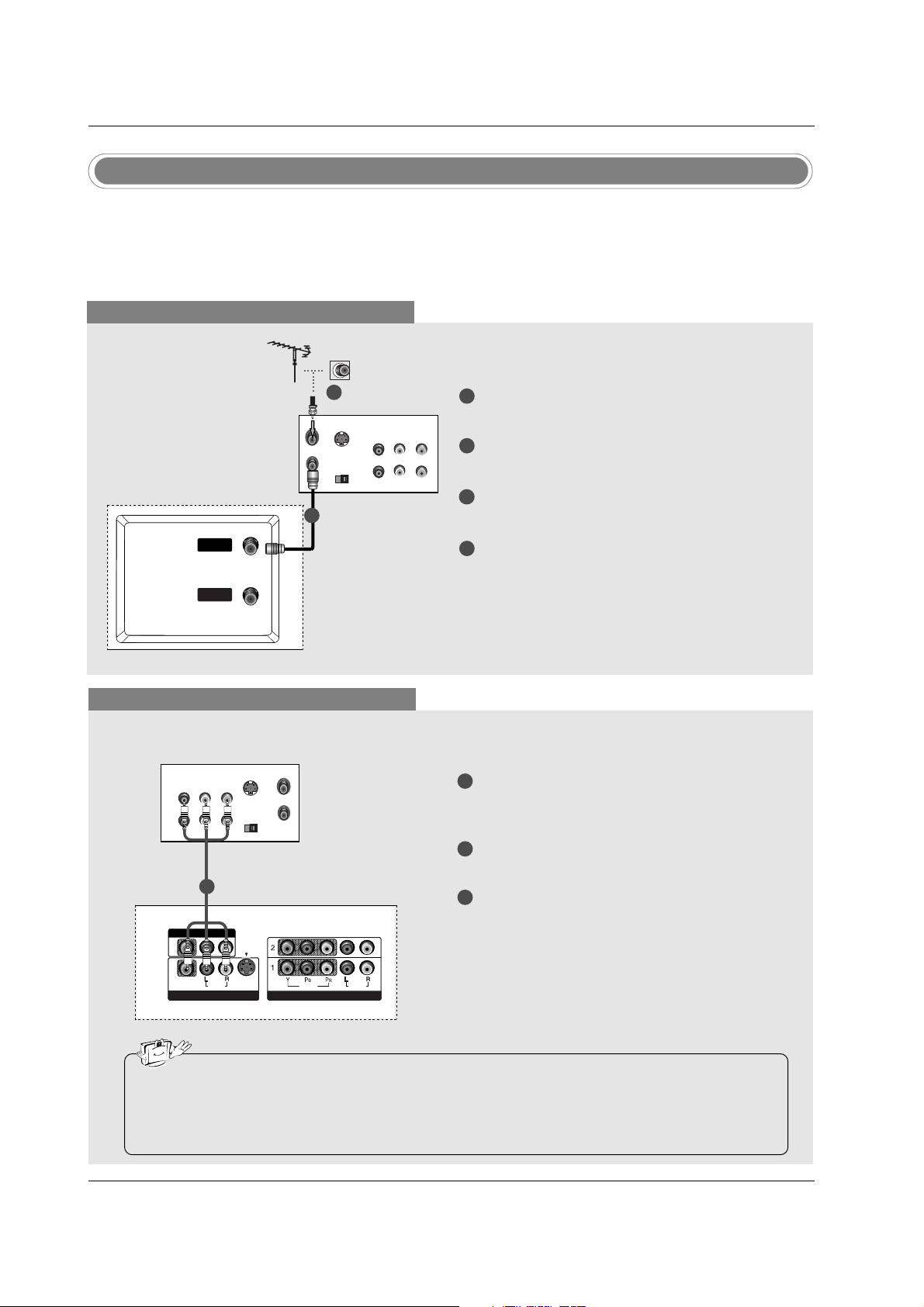
VCR Setup
When connecting with an antenna
S-VIDEO
OUT
IN
(R) AUDIO (L) VIDEO
34
OUTPUT
SWITCH
ANT OUT
ANT IN
ANTENNAANTENNA
IN
CABLECABLE
IN
When connecting with a RCA cable
S-VIDEO
OUT
IN
(R) AUDIO (L) VIDEO
34
OUTPUT
SWITCH
ANT OUT
ANT IN
VIDEO
AUDIO
MONO
( )
VIDEO
AUDIO
COMPONENT IN
S-VIDEO
AV IN 1V IN 1
AV OUTV OUT
ANTENNA
IN
CABLE
IN
VCR
1
2
3
Connect the AUDIO/VIDEO jacks between TV
and VCR. Match the jack colors (Video = yellow,
Audio Left = white, and Audio Right = red)
Insert a video tape into the VCR and press PLAY
on the VCR. (Refer to the VCR owner’s manual.)
Select AV 1 input source using the INPUT button
on the remote control.
- If connected to AV IN2, select AV2 input source.
• If you have a mono VCR, connect the audio cable from the VCR to the AUDIO L/MONO jack of the
set.
• This TV finds the connected input sources automatically for AV1, AV2 and Component 1-2. It is presumed that RGB and HDMI/DVI sources are connected.
1
1
2
3
4
Connect the RF antenna out socket of the VCR to
the Antenna socket on the set.
Connect the antenna cable to the RF antenna in
socket of the VCR.
Set VCR output switch to 3 or 4 and then tune TV
to the same channel number.
Insert a video tape into the VCR and press PLAY
on the VCR. (Refer to the VCR owner’s manual.)
VCR
1
2
23
Installation
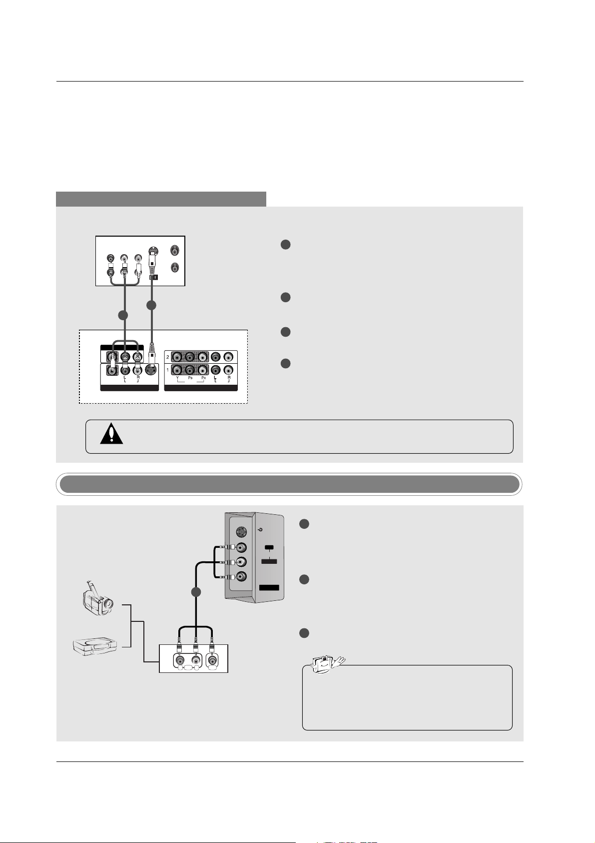
When connecting with an S-Video cable
S-VIDEO
OUT
IN
(R) AUDIO (L) VIDEO
34
OUTPUT
SWITCH
ANT OUT
ANT IN
VIDEO
AUDIO
( )
VIDEO
AUDIO
COMPONENT IN
S-VIDEO
AV IN 1
AV OUT
ANTENNA
IN
CABLE
IN
VIDEO
AUDIO
MONO
( )
VIDEO
AUDIO
COMPONENT IN
S-VIDEO
AV IN 1V IN 1
AV OUTV OUT
VCR
1
1
2
2
3
4
Connect the S-VIDEO output of the VCR to the SVIDEO input on the set. The picture quality is
improved; compared to normal composite (RCA
cable) input.
Connect the audio outputs of the VCR to the
AUDIO input jacks on the set.
Insert a video tape into the VCR and press PLAY
on the VCR. (Refer to the VCR owner’s manual.)
Select AV1 input source with using the INPUT
button on the remote control.
- If connected to AV IN2, select AV2 input source.
Do not connect to both Video and S-Video at the same time. In the event that you connect
both Video and the S-Video cables, only the S-Video will work.
V IN 2
MONO
AUDIO
S-VIDEO
VIDEO
Camcorder
Video Game Set
1
1
2
3
Connect the AUDIO/VIDEO jacks between TV
and external equipment. Match the jack colors
(Video = yellow, Audio Left = white, and Audio
Right = red).
Select AV2 input source with using the INPUT
button on the remote control.
- If connected to AV IN1 input, select AV1 input
source.
Operate the corresponding external equipment.
Refer to external equipment operating guide.
External AV Source Setup
• This TV finds the connected input sources
automatically for AV1, AV2 and Component 1-
2. It is presumed that RGB and HDMI/DVI
sources are connected.
i.e) 32LC2D**
S-VIDEO
AUDIO VIDEO
RL
AUDIO
L/MONO
VIDEO
AV IN 2
R
24
Installation
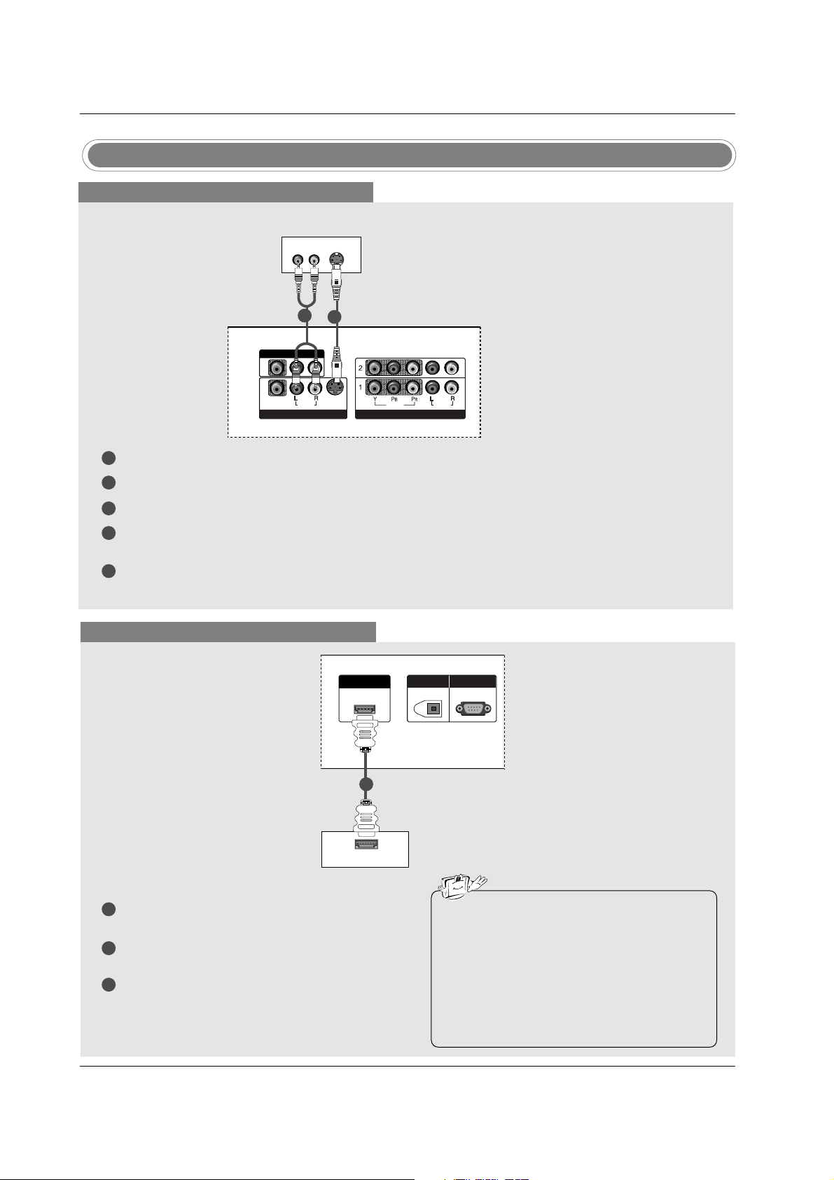
DVD Setup
When connecting with a S-Video cable
S-VIDEO
(R) AUDIO (L)
VIDEO
AUDIO
( )
VIDEO
AUDIO
COMPONENT IN
S-VIDEO
AV IN 1
AV OUT
VIDEOVIDEO
AUDIOUDIO
MONO
( )
VIDEOVIDEO
AUDIOUDIO
COMPONENT INCOMPONENT IN
S-VIDEOS-VIDEO
AV IN 1V IN 1
AV OUTV OUT
HDMI/DVI IN
DIGITAL AUDIO
OUT
OPTICAL
RS-232C IN
(CONTROL & SERVICE)
DVD
1
1
2
2
3
4
5
Connect the S-VIDEO output of the DVD to the S-VIDEO input on the set.
Connect the audio outputs of the DVD to the AUDIO input jacks on the set.
Turn on the DVD player, insert a DVD.
Select AV1 input source with using the INPUT button on the remote control.
- If connected to AV IN2, select AV 2 input source.
Refer to the DVD player's manual for operating instructions.
When connecting with a HDMI cable
1
2
3
Connect the HDMI output of the DVD to the
HDMI/DVI IN jack on the set.
Select HDMI/DVI input source with using the
INPUT button on the remote control.
Refer to the DVD player's manual for operating
instructions.
HDMI-DVD OUTPUT
HDMI/DVI IN
DIGITDIGITAL AAL AUDIO UDIO
OUTOUT
OPTICAL
RS-232C INRS-232C IN
(CONTROLOL & SERVICE)
DVD
1
• TV can receive the video and audio signal
simultaneously with using a HDMI cable.
• If the DVD supports Auto HDMI function, the
DVD output resolution will be automatically
set to 1280x720p.
• If the DVD does not support Auto HDMI, you
need to set the output resolution appropriately. To get the best picture quality, adjust the
output resolution of the DVD to 1280x720p.
25
Installation
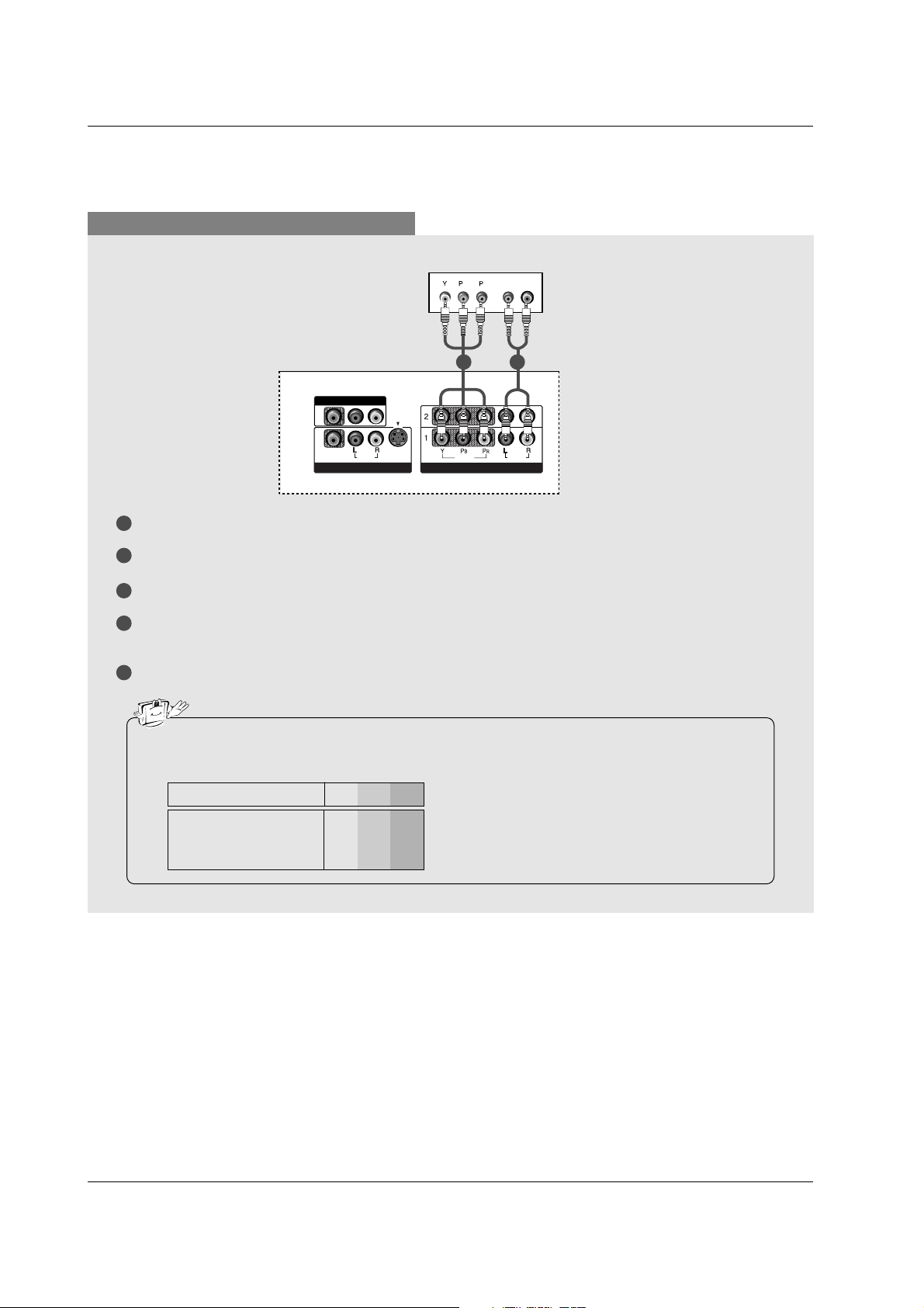
When connecting with a component cable
1
2
3
4
5
Connect the video outputs (Y, PB, PR) of the DVD to the COMPONENT IN VIDEO jacks on the set.
Connect the audio outputs of the DVD to the COMPONENT IN AUDIO jacks on the set.
Turn on the DVD player, insert a DVD.
Select Component 1 input source with using the INPUT button on the remote control.
- If connected to COMPONENT 2, select Component 2 input source.
Refer to the DVD player's manual for operating instructions.
• Component Input ports
To get better picture quality, connect a DVD player to the component input ports as shown below.
Y PB
PR
Component ports on the TV
Y
Y
Y
Y
Pb
B-Y
Cb
PB
Pr
R-Y
Cr
P
R
Video output ports
on DVD player
B
R
(R) AUDIO (L)
VIDEOVIDEO
AUDIOUDIO
MONO
( )
VIDEOVIDEO
AUDIOUDIO
COMPONENT INCOMPONENT IN
S-VIDEOS-VIDEO
AV IN 1V IN 1
AV OUTV OUT
HDMI/DVI IN
DIGITAL AUDIO
OUT
OPTICAL
RS-232C IN
(CONTROL & SERVICE)
DVD
1 2
26
Installation
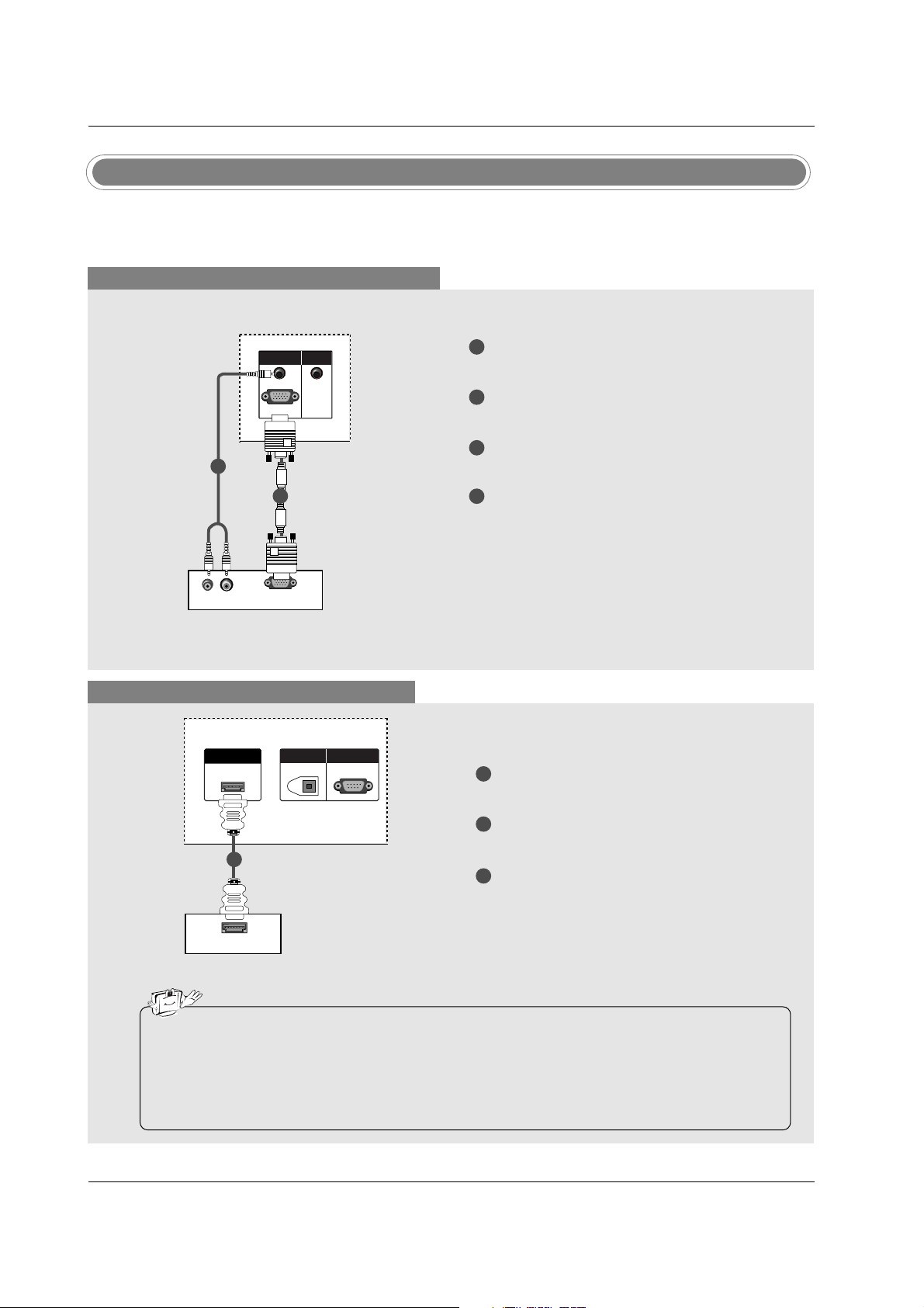
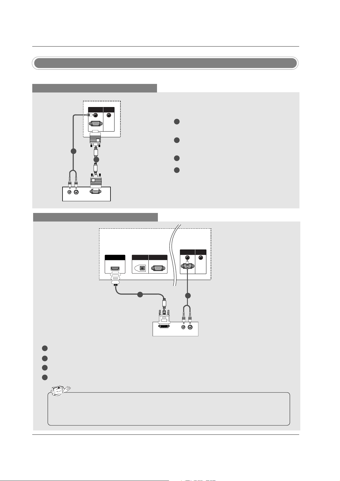
When connecting with a D-sub 15 pin cable
1
2
3
4
Connect the RGB output of the digital set-top box
to the RGB (PC/DTV) jack on the set.
Connect the audio outputs of the set-top box to
the AUDIO (RGB/DVI) jack on the set.
Turn on the digital set-top box. (Refer to the
owner’s manual for the digital set-top box.)
Select RGB-DTV input source with using the
INPUT button on the remote control.
- This TV can receive Digital Over-the-air/Cable signals without an external digital set-top box. However, if
you do receive Digital signals from a digital set-top box or other digital external device, refer to the figure
as shown below.
(R) AUDIO (L)
RGB-DTV OUTPUT
HDMI/DVI IN
DIGITAL AUDIO
OUT
OPTICAL
RS-232C IN
(CONTROL & SERVICE)
RGB (PC/DTV)
RGB INRGB IN
AUDIO (RGB/DVI)AUDIO (RGB/DVI)
REMOTEREMOTE
CONTROL IN
HDMI/DVI IN
DIGITAL AUDIO
OUT
OPTICAL
RS-232C IN
(CONTROL & SERVICE)
RGB (PC/DTV)
RGB IN
AUDIO (RGB/DVI)
REMOTE
CONTROL IN
REMOTE
CONTROL
Digital Set-top Box
HDSTB Setup
1
2
When connecting with a HDMI cable
1
2
3
Connect the HDMI output of the digital set-top
box to the HDMI/DVI IN jack on the set.
Select HDMI/DVI input source with using the
INPUT button on the remote control.
Turn on the digital set-top box. (Refer to the
owner’s manual for the digital set-top box.)
Digital Set-top Box
• TV can receive the video and audio signal simultaneously with using a HDMI cable.
• If the digital set-top box supports Auto HDMI function, output resolution of the digital set-top box will
be automatically set to 1280x720p.
• If the digital set-top box does not support Auto HDMI, you need to set the output resolution appropriately. To get the best picture quality, adjust the output resolution of the digital set-top box to
1280x720p.
HDMI-DTV OUTPUT
HDMI/DVI IN
DIGITDIGITAL AAL AUDIO UDIO
OUTOUT
OPTICAL
RS-232C INRS-232C IN
(CONTR(CONTROLOL & SERVICE)VICE)
1
27
Installation
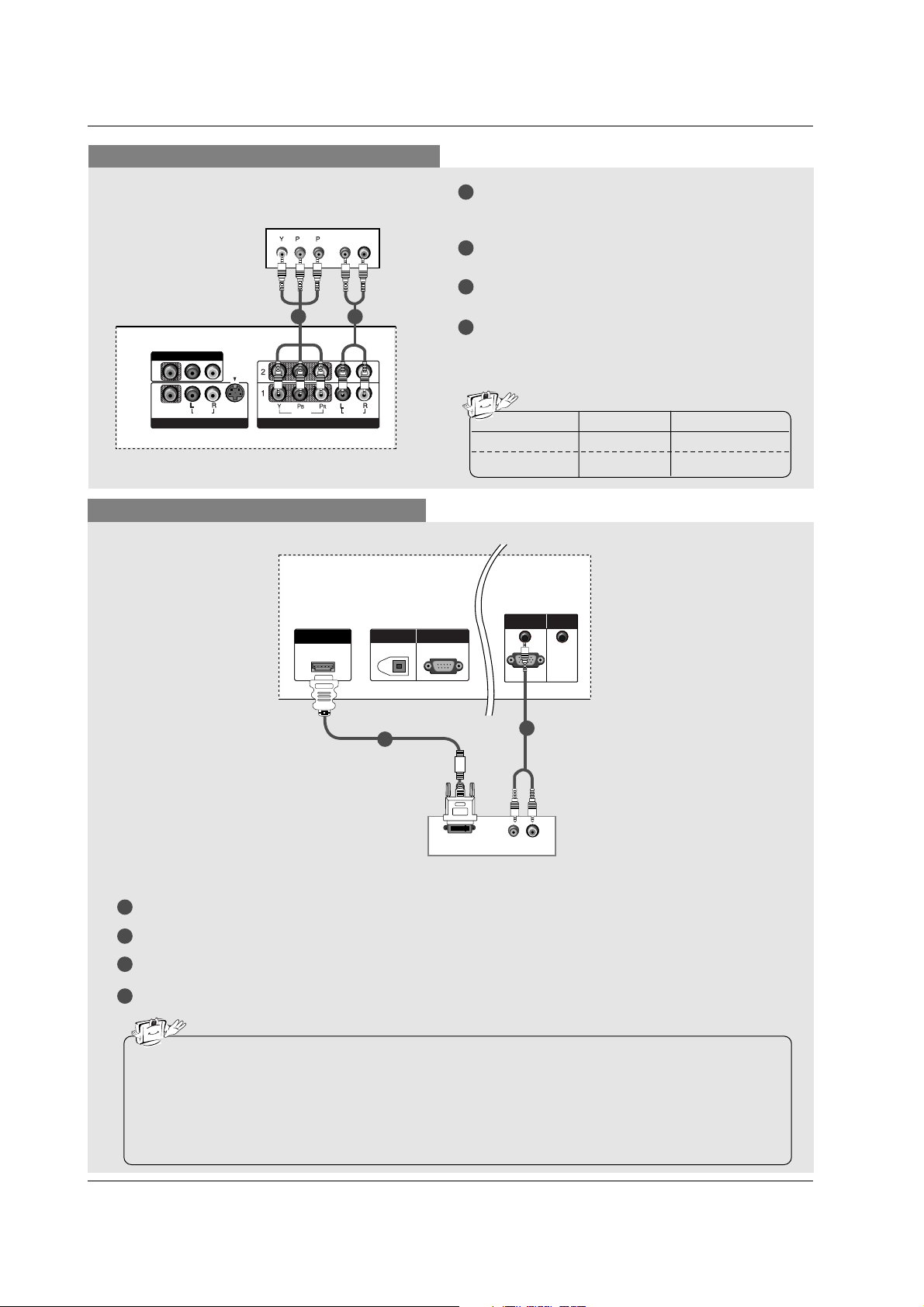
When connecting with a Component cable
1
2
3
4
Connect the video outputs (Y, PB, PR) of the digital set-top box to the COMPONENT IN VIDEO
jacks on the set.
Connect the audio output of the digital set-top box
to the COMPONENT IN AUDIO jacks on the set.
Turn on the digital set-top box. (Refer to the
owner’s manual for the digital set-top box.)
Select Component 1 input source with using the
INPUT button on the remote control.
- If connected to COMPONENT 2, select
Component 2 input source.
B
R
(R) AUDIO (L)
VIDEOVIDEO
AUDIOUDIO
MONO
( )
VIDEOVIDEO
AUDIOUDIO
COMPONENT INCOMPONENT IN
S-VIDEOS-VIDEO
AV IN 1V IN 1
AV OUTV OUT
HDMI/DVI IN
DIGITAL AUDIO
OUT
OPTICAL
RS-232C IN
(CONTROL & SERVICE)
Signal
480i
480p/720p/1080i
Component1/2
Yes
Yes
RGB-DTV, HDMI/DVI
No
Yes
21
Digital Set-top Box
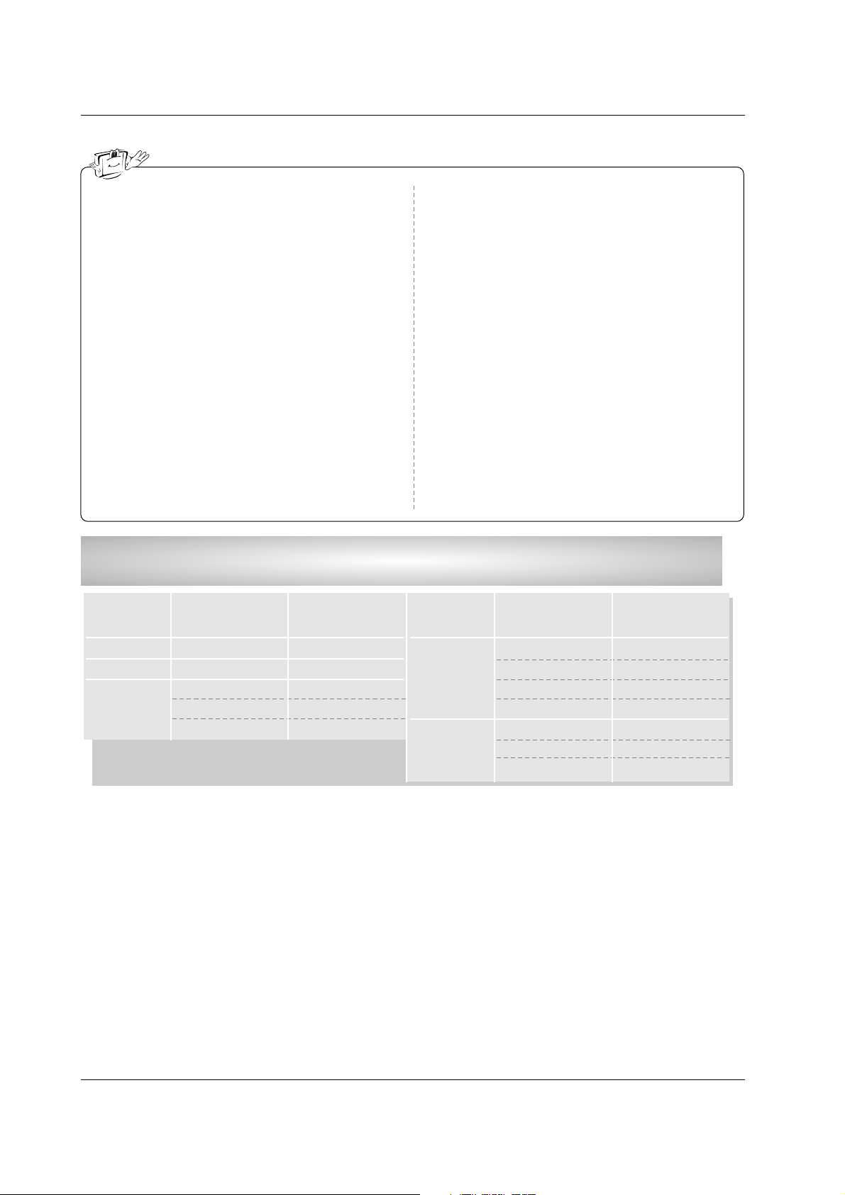
When connecting with a HDMI to DVI cable
1
2
3
4
Connect the DVI output of the digital set-top box to the HDMI/DVI IN jack on the set.
Connect the audio outputs of the set-top box to the AUDIO (RGB/DVI) jack on the set.
Turn on the digital set-top box. (Refer to the owner’s manual for the digital set-top box.)
Select HDMI/DVI input source with using the INPUT button on the remote control.
HDMI/DVI IN
DIGITAL AUDIO
OUT
OPTICAL
RS-232C IN
(CONTROL & SERVICE)
(R) AUDIO (L)
DVI-DTV OUTPUT
HDMI/DVI IN
DIGITDIGITAL AAL AUDIO UDIO
OUTOUT
OPTICAL
RS-232C INRS-232C IN
(CONTR(CONTROL & SERSERVICE)
RGB (PC/DTV)
RGB INRGB IN
AUDIO (RGB/DVI)AUDIO (RGB/DVI)
REMOTEREMOTE
CONTROL IN
Digital Set-top Box
1
2
• If the digital set-top box has a DVI output and no HDMI output, a separated audio connection is necessary.
• If the digital set-top box supports Auto DVI function, the output resolution of the digital set-top box will
be automatically set to 1280x720p.
• If the digital set-top box does not support Auto DVI, you need to set the output resolution appropriately. To get the best picture quality, adjust the output resolution of the digital set-top box to
1280x720p.
28
Installation
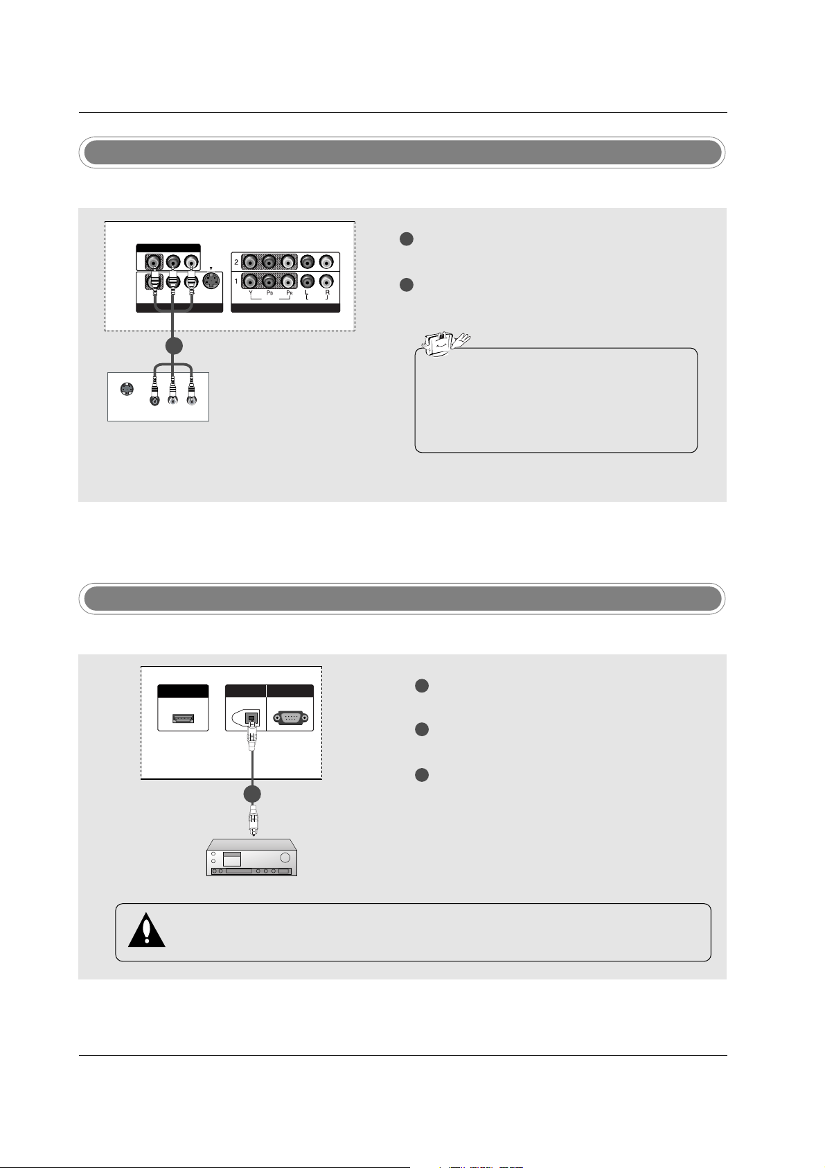
Digital Audio Output
1
2
3
Connect one end of an optical cable to the TV
Digital Audio Optical Output port.
Connect the other end of the optical cable to the
digital audio optical input on the audio equipment.
See the external audio equipment instruction
manual for operation.
When connecting with external audio equipments, such as amplifiers or speakers, please
turn the TV speakers off. (Refer to p.43)
HDMI/DVI IN
DIGITDIGITAL AAL AUDIO UDIO
OUTOUT
OPTICAL
RS-232C INRS-232C IN
(CONTROL & SERVICE)
- Send the TV’s audio to external audio equipment (stereo system) via the Digital Audio Output Optical port.
CAUTION
Do not look into the optical output port. Looking at the laser beam may damage your vision.
1/2
Monitor Out Setup
1
2
Connect the second TV or monitor to the TV’s AV
OUTPUT jacks.
See the Operating Manual of the second TV or
monitor for further details regarding that device’s
input settings.
S-VIDEO
IN
(R) AUDIO (L)
VIDEO
VIDEOVIDEO
AUDIOUDIO
MONO
( )
VIDEOVIDEO
AUDIOUDIO
COMPONENT INCOMPONENT IN
S-VIDEOS-VIDEO
AV IN 1V IN 1
AV OUTV OUT
- The TV has a special signal output capability which allows you to hook up a second TV or monitor.
1/2
• Component 1-2, RGB-PC/RGB-DTV,
HDMI/DVI, DTV input sources cannot be used
for Monitor out.
• We recommend to use the video and audio
output jacks for VCR recording.
29
Installation
- This TV provides Plug and Play capability, meaning that the PC adjusts automatically to the TV's settings.
PC Setup
When connecting with a D-sub 15 pin cable
1
2
3
4
Connect the RGB output of the PC to the RGB
(PC/DTV) jack on the set.
Connect the PC audio outputs to the AUDIO
(RGB/DVI) jack on the set.
Turn on the PC and the set.
Select RGB-PC input source with using the
INPUT button on the remote control.
(R) AUDIO (L)
RGB-PC OUTPUT
RGB (PC/DTV)
RGB INRGB IN
AUDIO (RGB/DVI)AUDIO (RGB/DVI)
REMOTEREMOTE
CONTROL INCONTROL IN
HDMI/DVI IN
DIGITAL AUDIO
OUT
OPTICAL
RS-232C IN
(CONTROL & SERVICE)
RGB (PC/DTV)
RGB IN
AUDIO (RGB/DVI)
REMOTE
CONTROL IN
1
2
PC
When connecting with a HDMI to DVI cable
1
2
3
4
Connect the DVI output of the PC to the HDMI/DVI IN jack on the set.
Connect the audio outputs of the PC to the AUDIO (RGB/DVI) jack on the set.
Turn on the PC and the set.
Select HDMI/DVI input source with using the INPUT button on the remote control.
(R) AUDIO (L)
DVI-PC OUTPUT
HDMI/DHDMI/DVI INVI IN
DIGITDIGITAL AAL AUDIO UDIO
OUTOUT
OPTICAL
RS-232C INRS-232C IN
(CONTR(CONTROLOL & SERSERVICE)VICE)
RGB (PC/DTV)
RGB INRGB IN
AUDIO (RGB/DVI)AUDIO (RGB/DVI)
REMOTEREMOTE
CONTROL INCONTROL IN
PC
• If the PC has a DVI output and no HDMI output, a separated audio connection is necessary.
• If the PC does not support Auto DVI, you need to set the output resolution appropriately. To get the
best picture quality, adjust the output resolution of PC graphics card's output resolution to
1024x768, 60Hz.
1
2
30
Installation
1. To get the best picture quality, adjust the PC
graphics card to 1024x768, 60Hz.
2. Depending on the graphics card, DOS mode may
not work if a HDMI to DVI Cable is in use.
3. When Source Devices connected with HDMI/DVI
Input, output PC Resolution (VGA, SVGA, XGA),
Position and Size may not fit to Screen.Press the
ADJUST button to adjust the screen Position of TV
SET and contact an PC graphics card service center.
4. When Source Devices connected with HDMI/DVI
Input, output TV SET Resolution (480p, 720p,
1080i) and TV SET Display fit EIA/CEA-861-B
Specification to Screen. If not, refer to the Manual
of HDMI/DVI Source Devices or contact your service center.
5. In case HDMI/DVI Source Devices is not connected Cable or poor cable connection, "NO SIGNAL"
OSD display in HDMI/DVI Input. In case that Video
Resolution is not supported TV SET output in
HDMI/DVI Source Devices, "INVALID FORMAT"
OSD display. Refer to the Manual of HDMI/DVI
Source Devices or contact your service center.
6. Check the image on your TV. There may be noise
associated with the resolution, vertical pattern,
contrast or brightness in PC, HDMI/DVI mode. If
noise is present, change the PC or HDMI/DVI
mode to another resolution, change the refresh
rate to another rate or adjust the brightness and
contrast on the menu until the picture is clear. If the
refresh rate of the PC graphic card can not be
changed, change the PC graphic card or consult
the manufacturer of the PC graphic card.
7. Avoid keeping a fixed image on the TV's screen for
a long period of time. The fixed image may become
permanently imprinted on the screen.
8. The synchronization input form for Horizontal and
Vertical frequencies is separate.
Supported Display Resolution
(RGB-PC, HDMI/DVI Mode)
Resolution
* 640x350
* 720x400
640x480
Horizontal
Frequency (kHz)
31.468
31.469
31.469
37.861
37.500
70.08
70.08
59.94
72.80
75.00
Vertical
Frequency (Hz)
Resolution
* RGB-PC only
800x600
1024x768
Horizontal
Frequency (kHz)
35.156
37.879
48.077
46.875
48.363
56.476
60.023
56.25
60.31
72.18
75.00
60.00
70.06
75.02
Vertical
Frequency (Hz)
 Loading...