

LG 32LM6400-DJ, 47LM6400-DJ, 32LM6400, 55LM7600-DA, 55LM7600 Service Manual
...
Printed in KoreaP/NO : MFL67362716 (1205-REV00)
CHASSIS : LT22E
MODEL : 47LM6400 47LM6400-DJ
CAUTION
BEFORE SERVICING THE CHASSIS,
READ THE SAFETY PRECAUTIONS IN THIS MANUAL.
LED LCD TV
SERVICE MANUAL
North/Latin America http://aic.lgservice.com
Europe/Africa http://eic.lgservice.com
Asia/Oceania http://biz.lgservice.com
Internal Use Only

- 2 -
LGE Internal Use OnlyCopyright © LG Electronics. Inc. All rights reserved.
Only for training and service purposes
CONTENTS
CONTENTS .............................................................................................. 2
PRODUCT SAFETY ................................................................................. 3
SPECIFICATION ....................................................................................... 4
ADJUSTMENT INSTRUCTION .............................................................. 10
BLOCK DIAGRAM .................................................................................. 21
EXPLODED VIEW .................................................................................. 27
SCHEMATIC CIRCUIT DIAGRAM ..............................................................

- 3 -
LGE Internal Use OnlyCopyright © LG Electronics. Inc. All rights reserved.
Only for training and service purposes
Many electrical and mechanical parts in this chassis have special safety-related characteristics. These parts are identified by in the
Schematic Diagram and Exploded View.
It is essential that these special safety parts should be replaced with the same components as recommended in this manual to prevent
Shock, Fire, or other Hazards.
Do not modify the original design without permission of manufacturer.
General Guidance
An isolation Transformer should always be used during the
servicing of a receiver whose chassis is not isolated from the AC
power line. Use a transformer of adequate power rating as this
protects the technician from accidents resulting in personal injury
from electrical shocks.
It will also protect the receiver and it's components from being
damaged by accidental shorts of th e cir cuitry that may be
inadvertently introduced during the service operation.
If any fuse (or Fusible Resistor) in this TV receiver is blown,
replace it with the specified.
When replacing a high wattage resistor (Oxide Metal Film Resistor,
over 1 W), keep the resistor 10 mm away from PCB.
Keep wires away from high voltage or high temperature parts.
Before returning the receiver to the customer,
always perform an AC leakage current check on the exposed
metallic parts of the cabinet, such as antennas, terminals, etc., to
be sure the set is safe to operate without damage of electrical
shock.
Leakage Current Cold Check(Antenna Cold Check)
With the instrument AC plug removed from AC source, connect an
electrical jumper across the two AC plug prongs. Place the AC
switch in the on position, connect one lead of ohm-meter to the AC
plug prongs tied together and touch other ohm-meter lead in turn to
each exposed metallic parts such as antenna terminals, phone
jacks, etc.
If the exposed metallic part has a return path to the chassis, the
measured resistance should be between 1 MΩ and 5.2 MΩ.
When the exposed metal has no return path to the chassis the
reading must be infinite.
An other abnormality exists that must be corrected before the
receiver is returned to the customer.
Leakage Current Hot Check (See below Figure)
Plug the AC cord directly into the AC outlet.
Do not use a line Isolation Transformer during this check.
Connect 1.5 K / 10 watt resistor in parallel with a 0.15 uF capacitor
between a known good earth ground (Water Pipe, Conduit, etc.)
and the exposed metallic parts.
Measure the AC voltage across the resistor using AC voltmeter
with 1000 ohms/volt or more sensitivity.
Reverse plug the AC cord into the AC outlet and repeat AC voltage
measurements for each exp ose d metallic par t. Any voltage
measured must not exceed 0.75 volt RMS which is corresponds to
0.5 mA.
In case any measurement is out of the limits specified, there is
possibility of shock hazard and the set must be checked and
repaired before it is returned to the customer.
Leakage Current Hot Check circuit
IMPORTANT SAFETY NOTICE
SAFETY PRECAUTIONS

- 4 -
LGE Internal Use OnlyCopyright © LG Electronics. Inc. All rights reserved.
Only for training and service purposes
SPECIFICATION
NOTE : Specifications and others are subject to change without notice for improvement
.
1. Application range
This spec sheet is applied to the 32/42/47/55/60/65LCD TV
used LT22E chassis.
2. Test condition
Each part is tested as below without special notice.
1) Temperature : 25 ºC ± 5 ºC (77 ºF ± 9 ºF), CST : 40 ºC±5 ºC
2) Relative Humidity: 65 % ± 10 %
3) Power Voltage : S ta ndard i nput voltage (100~240V@
50/60Hz)
4) Specification and performance of each parts are followed
ea ch drawing and s pe cificatio n b y p art number in
accordance with BOM.
5) The receiver must be operated for about 5 minutes prior to
the adjustment.
3. Test method
1) Performance: LGE TV test method followed
2) Demanded other specification
- Safety : CE, IEC specification
- EMC : CE, IEC

- 5 -
LGE Internal Use OnlyCopyright © LG Electronics. Inc. All rights reserved.
Only for training and service purposes
4. General Specification
No Item Specication Remark
1. Display Screen Device 32” wide Color Display Module
37” wide Color Display Module
42” wide Color Display Module
47” wide Color Display Module
55” wide Color Display Module
60” wide Color Display Module
65” wide Color Display Module
Resolution: 1920*1080
Resolution: 1920*1080
Resolution: 1920*1080
Resolution: 1920*1080
Resolution: 1920*1080
Resolution: 1920*1080
Resolution: 1920*1080
2. Aspect Ratio 16:9 All
3. LCD Module 32” TFT WUXGA LCD
37” TFT WUXGA LCD
42” TFT WUXGA LCD
47” TFT WUXGA LCD
55” TFT WUXGA LCD
60” TFT WUXGA LCD
65” TFT WUXGA LCD
4. Operating Environment 1) Temp. : 0 ~ 40 deg LGE SPEC
2) Humidity : 0 ~ 85%
5. Storage Environment 1) Temp. : -20 ~ 60 deg
2) Humidity : 10 ~ 90%
6. Input Voltage AC100 ~ 240V, 50/60Hz
7. Power Consumption(Max) =
LCD(Module) + Backlight(LED)
FHD 60Hz
Edge LED
32” 50 W Normal : T320HVN01.0 [32LS5700-DA/B]
Normal : LC320EUN-SEM1 [32LS5700-DA/B]
42” 70 W Normal : LC420EUE-SEM1 [42LS5700-DA/B]
47” 85 W Normal : LC470EUE-SEM1 [47LS5700-DA/B]
55” W Normal : LC550EUE-SEM1 [55LS5700-DA/B]
FHD
T120Hz
Edge LED
32” 45 W FPR : LC320EUN-SEF2 [32LM6200-DA]
50 W FPR : LC320EUA-KEF1 [32LM6400-DA]
37” 50 W FPR : LC370EUN-SEF2 [37LM6200-DA]
42” 60 W FPR : LC420EUE-SEF1 [42LM6200-DA]
60 W FPR : LC420EUG-KEF1 [42LM6600-DA]
FPR : LC420EUG-KEF1 [42LM6690-DA]
FPR : LC420EUG-KEF1 [42LM6700-DC]
FPR : LC420EUG-KEF1 [42LM6400-DJ]
47” 90 W FPR : LC470EUE-SEF1 [47LM6200-DA]
70 W FPR : LC470EUG-KEF1 [47LM6400-DJ]
FPR : LC470EUG-KEF1 [47LM6690-DC]
FPR : LC470EUG-KEF1 [47LM6700-DA]
55” 115 W FPR : LC550EUE-SEF1 [55LM6200-DA]
70 W FPR : LC550EUG-KEF1 [55LM6400-DJ]
FPR : LC550EUG-KEF1 [55LM6700-DA]
FHD
M120Hz
Edge LED
65” 230 W FPR : T645HB01 V0 [65LM6200-DA]
FHD
T240Hz
Edge LED
42” 70 W FPR : LC420EUH-KEF1 [42LM7600-DA]
47” 90 W FPR : LC470EUH-KEF1[47LM7600-DA]
55” 120 W FPR : LC550EUH-KEF1[55LM7600-DA]

- 6 -
LGE Internal Use OnlyCopyright © LG Electronics. Inc. All rights reserved.
Only for training and service purposes
8. LCD Module Size Maker Inch (H) × (V) × (D)
LGD 32” 727.4 x 429.0 x 22.7 LC320EUN-SEM2
727.4 x 429.0 x 20.0
698.40 x 392.85 x 10.8
37” 837.2 x 490.6 x 22.7 LC370EUN-SEF2 : Edge 3D_T120Hz
42” 960.4 x 560.4 x 17.4 LC420EUE-SEF1 : Edge 3D_T120Hz
LC420EUE-SEM1 : Edge Non-3D_60Hz
968.4 x 564 x 10.8
968.4 x 564 x 12.2
47” 1070.6 x 622.0 x 22.0 LC470EUE-SEF1 : Edge 3D_T120Hz
LC470EUE-SEM1 : Edge Non-3D_60Hz
1078.6 x 626.0 x 10.8
1078.6 x 626.0 x 12.2
1054.5 x 600.0 x 1.8
1054.5 x 600.0 x 1.8
55” 1244.6 x 720.9 x 22.0 LC550EUE-SEF1 : Edge 3D_T120Hz
1228.6 x 711.4 x 20.7 LC550EUG-KEF1 : Edge 3D_T120Hz
LC550EUH-KEF1 : Edge 3D_T240Hz
1220.8 x 693.8 x 1.8
1220.8 x 693.8 x 1.8
AUO 32” 727.4 x 429.0 x 20.0 T320HVN01.0 : Edge Non-3D_60Hz
65” 1508.0 x 878.0 x 12.8 T645HB01 V0 : Edge 3D_M120Hz
Pixel Pitch Maker Inch (H) × (V) × (D)
LGD 32” 0.36375 x 0.36375 LC320EUN-SEF2 : Edge 3D_T120Hz
37” 0.4209 x 0.4209 LC370EUN-SEF2 : Edge 3D_T120Hz
42” 0.4845 x 0.4845
LC420EUE-SEF1 : Edge 3D_T120Hz
LC420EUE-SEM1 : Edge Non-3D_60Hz
47” 0.5415 x 0.5415 LC470EUE-SEF1 : Edge 3D_T120Hz
LC470EUE-SEM1 : Edge Non-3D_60Hz
55” 0.630 x 0.630 LC550EUE-SEF1 : Edge 3D_T120Hz
LC550EUG-KEF1 : Edge 3D_T120Hz
LC550EUH-KEF1 : Edge 3D_T240Hz
AUO 32” 0.36375 x 0.36375 T320HVN01.0 : Edge Non-3D_60Hz
65” 0.744 x 0.744 T645HB01 V0 : Edge 3D_M120Hz
Back Light LGD 32” Edge-LED LC320EUN-SEF2
LC320EUA-KEF1
37” Edge-LED LC370EUN-SEF2
42” Edge-LED LC420EUE-SEF1
LC420EUG-KEF1
LC420EUE-SEM1
LC420EUH-KEF1
47” Edge-LED LC470EUE-SEF1
LC470EUG-KEF1
LC470EUE-SEM1
LC470EUH-KEF1
55” Edge-LED LC550EUE-SEF1
LC550EUG-KEF1
LC550EUH-KEF1
AUO 32” Edge-LED T320HVN01.0
65” Edge-LED T645HB01 V0
- 7 -
LGE Internal Use OnlyCopyright © LG Electronics. Inc. All rights reserved.
Only for training and service purposes
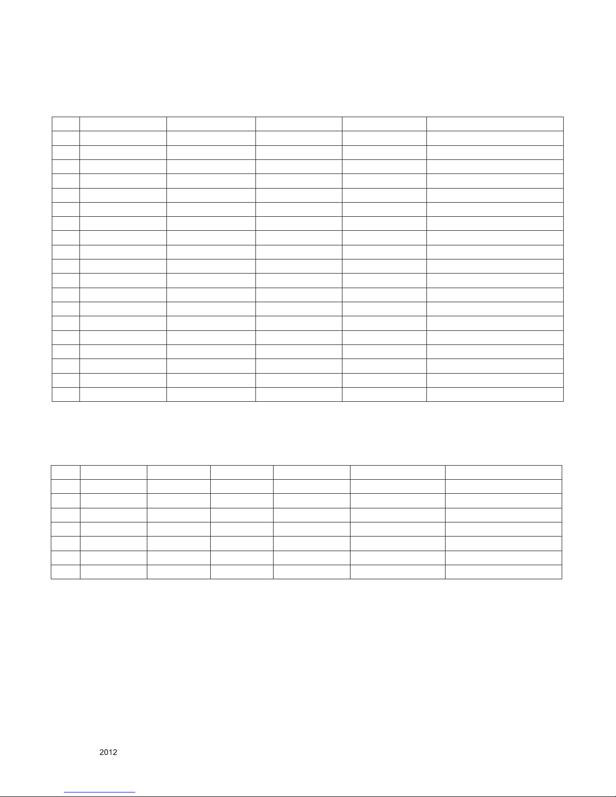
5. External Input Support Format
5.1. Component(Y, Pb, Pr)
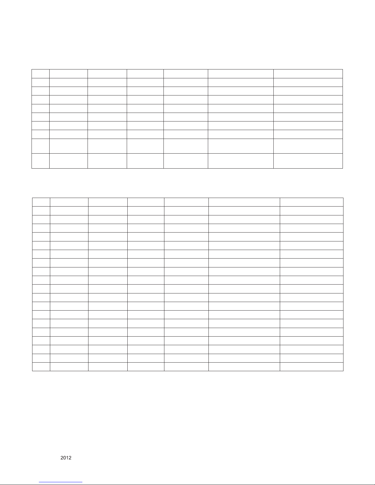
5.2. RGB Input (PC) : RGB-PC EDID DATA : Refer to adjust specification.
No. Resolution H-freq(kHz) V-freq(Hz) Remark
1. 720*480i 15.73 59.94 13.500 SDTV, DVD 480I(525I)
2 720*480i 15.73 60.00 13.514 SDTV, DVD 480I(525I)
3. 720*576i 15.625 50.00 13.500 SDTV, DVD 576I(625I) 50Hz
4 720*480p 31.47 59.94 27.000 SDTV 480P
5 720*480p 31.50 60.00 27.027 SDTV 480P
6 720*576p 31.25 50.00 27.000 SDTV 576P 50Hz
7 1280*720 44.96 59.94 74.176 HDTV 720P
8 1280*720 45.00 60.00 74.250 HDTV 720P
9 1280*720 37.50 50.00 74.25 HDTV 720P 50Hz
10 1920*1080 28.125 50.00 74.250 HDTV 1080I 50Hz,
11 1920*1080 33.72 59.94 74.176 HDTV 1080I
12 1920*1080 33.75 60.00 74.25 HDTV 1080I
13 1920*1080 26.97 23.976 63.296 HDTV 1080P
14 1920*1080 27.00 24.000 63.36 HDTV 1080P
15 1920*1080 33.71 29.97 79.120 HDTV 1080P
16 1920*1080 33.75 30.00 79.20 HDTV 1080P
17 1920*1080 56.25 50 148.5 HDTV 1080P
18 1920*1080 67.432 59.94 148.350 HDTV 1080P
19 1920*1080 67.5 60.00 148.5 HDTV 1080P
No Resolution H-freq(kHz) V-freq.(Hz) Pixel clock (MHz) Proposed Remark
1. 640*350 31.468 70.09 25.17 EGA
2 720*400 31.469 70.08 28.32 DOS
3. 640*480 31.469 59.94 25.17 VESA(VGA)
4 800*600 37.879 60.317 40 VESA(SVGA)
5 1024*768 48.363 60.004 65 VESA(XGA)
6 1360*768 47.712 60.015 84.75 VESA(WXGA)
7 1920*1080 67.5 60.00 138.50 WUXGA (CEA 861D) FHD Only
- 8 -
LGE Internal Use OnlyCopyright © LG Electronics. Inc. All rights reserved.
Only for training and service purposes
5.3. HDMI EDID DATA : Refer to adjust specification
5.3.1. PC mode
No Resolution H-freq(kHz) V-freq.(Hz) Pixel clock(MHz) Proposed Remarks
1 640*350 31.468 70.09 25.17 EGA
2 720*400 31.469 70.09 28.32 DOS
3 640*480 31.469 59.94 25.17 VESA(VGA)
4 800*600 37.879 60.317 40 VESA(SVGA)
5 1024*768 48.363 60.004 65 VESA(XGA)
6 1152*864 54.348 60.053 80.002 VESA(VGA)
7 1360*768 47.712 60.015 84.75 VESA(WXGA)
8
1280*1024 63.981 60.02 109.00 SXGA
Only FHD Model
(Support to HDMI-PC)
9
1920*1080 67.5 60 148.5
WUXGA
(Reduced Blanking)
Only FHD Model
No Resolution H-freq(kHz) V-freq.(Hz) Pixel clock(MHz) Proposed Remarks
1 720*480 15.73 59.94 13.500 SDTV, DVD 480I(525I) Spec. out but display
2 720*480 15.75 60.00 13.514 SDTV, DVD 480I(525I)
3 720*576 15.625 50.00 13.500 SDTV, DVD 576I(625I) 50Hz
4 720*480 31.47 59.94 27 SDTV 480P
5 720*480 31.5 60.00 27.027 SDTV 480P
6 720*576 31.25 50.00 27 SDTV 576P
7 1280*720 44.96 59.94 74.176 HDTV 720P
8 1280*720 45 60.00 74.25 HDTV 720P
9 1280*720 37.5 50.00 74.25 HDTV 720P
10 1920*1080 28.125 50.00 74.25 HDTV 1080I
11 1920*1080 33.72 59.94 74.176 HDTV 1080I
12 1920*1080 33.75 60.00 74.25 HDTV 1080I
13 1920*1080 26.97 23.976 63.296 HDTV 1080P
14 1920*1080 27.00 24.000 63.36 HDTV 1080P
15 1920*1080 33.71 29.97 79.120 HDTV 1080P
16 1920*1080 33.75 30.00 79.20 HDTV 1080P
17 1920*1080 56.25 50.00 148.5 HDTV 1080P
18 1920*1080 67.432 59.94 148.350 HDTV 1080P
19 1920*1080 67.5 60.00 148.5 HDTV 1080P
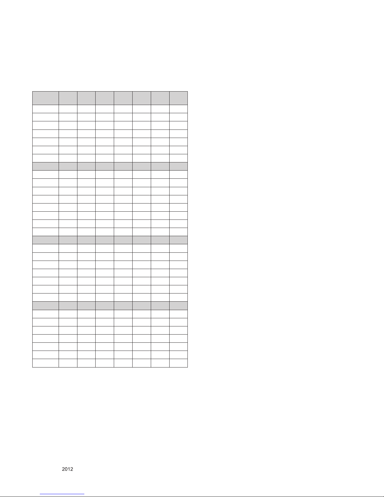
5.3.2. DTV mode

- 9 -
LGE Internal Use OnlyCopyright © LG Electronics. Inc. All rights reserved.
Only for training and service purposes
5.3.3. 3D mode
No. Resolution H-freq(kHz) V-freq.(kHz) Pixel clock(MHz) Proposed Remarks
*** HDMI 1.4
1 1280*720 75 50 148.5 HDTV 720P Frame packing
2 1280*720 37.5 50 74.25 HDTV 720P Side by Side(half), Top and Bottom
3. 1280*720 89.9 59.94 148.35 HDTV 720P Frame packing
90 60 148.5
4 1280*720 45 60 74.25 HDTV 720P Side by Side(half), Top and Bottom
5 1920*1080 53.95 23.95 148.35 HDTV 1080P Frame packing
54 24 148.5
6 1920*1080 27 24 74.25 HDTV 108 0P Side by Side(half), Top and Bottom
7 1920*1080 33.7 30 89.1 HDTV 1080P Side by Side(half), Top and Bottom
8 1920*1080 67.5 60 148.5 HDTV 1080P Side by Side(half), Top and bottom
9 1920*1080 56.25 50 148.5 HDTV 1080P Side by Side(half), Top and bottom,
10 1920*1080 33.7 60 74.25 HDTV 1080i Side by Side(half), Top and Bottom
11 1920*1080 28.1 50 74.25 HDTV 1080i Side by Side(half), Top and Bottom
*** HDMI 1.3
1 1280*720 45.00 60.00 74.25 HDTV 720P Side by Side, Top & Bottom
2 1280*720 37.500 50 74.25 HDTV 720P Side by Side, Top & Bottom
3 1920*1080 33.75 60.00 74.25 HDTV 1080I Side by Side, Top & Bottom
4 1920*1080 28.125 50.00 74.25 HDTV 1080I Side by Side, Top & Bottom
5 1920*1080 27.00 24.00 74.25 HDTV 1080P
Side by Side, Top & Bottom, Checkerboard
6 1920*1080 33.75 30.00 74.25 HDTV 1080P
Side by Side, Top & Bottom, Checkerboard
7 1920*1080 67.50 60.00 148.5 HDTV 1080P
Side by Side, Top & Bottom, Checkerboard
Single Frame Sequential
8 1920*1080 56.25 50 148.5 HDTV 1080P
Side by Side, Top & Bottom, Checkerboard
Single Frame Sequential

- 10 -
LGE Internal Use OnlyCopyright © LG Electronics. Inc. All rights reserved.
Only for training and service purposes
ADJUSTMENT INSTRUCTION
1. Application Range
This spec. sheet is applied all of the 32”/37”/42”/47”/55”/65”
LCD TV, LT22E chassis by manufacturing LG TV Plant all over
the world
2. Specification
(1) Because this is not a hot chassis, it is not necessary to use
an isolation transformer. However, the use of isolation
transformer will help protect test instrument..
(2) Adjustment must be done in the correct order
(3) The adjustment must be performed in the circumstance of
25 ºC ±5 ºC of temperature and 65±10% of relative
humidity if there is no specific designation.
(4) The input voltage of the receiver must keep 100~220V,
50/60Hz
(5) Before adjustment, execute Heat-Run for 5 minutes at RF
no signal.
3. Adjustment items
3.1. PCB assembly adjustment items
(1) MAC Address, ESN Key and Wide-vine Key D/L
(2) LAN Test( Ping-Test )
(3) Main S/W program download : Using USB Memory stick
(4) Input Tool - Option
(5) Download EDID : EDID data are automatically downloaded
when adjusting the Tool Option.
(6) ADC Calibration – RGB & Component
(7) Check SW Version
3.2. SET assembly adjustment items
(1) Input Area option.
(2) Adjustment of White Balance : Auto
(3) Adjustment of White Balance : Manual
(4) Intelligent Sensor Inspection Guide
(5) LAN Inspection Guide
(6) Widevine Key Inspection Guide
(7) Model name & Serial number D/L
(8) Wi-Fi MAC Address Check
(9) Local Dimming Inspection Guide
(10) Preset CH information
(11) Internal Press Test
(12) Motion Remote controller Inspection
(13) 3D Function test
(14) Outgoing Condition Conguration
(15) Sound spec
(16) Factoring Option Data input.
4. PCB assembly adjustment method
4.1. MAC Address, ESN Key and Wide-vine
Key Download
■ D/L Program : keydownload.exe
4.1.1. Equipment & Condition
1) Play file: keydownload.exe
2) Key Write: Com 1,2,3,4 and 115200 (Baudrate)
3) Barcode: Com 1,2,3,4 and 9600 (Baudrate)
4.1.2. Process
1) Execute “keydownload.exe” on PC
2) Select the download items.
3) Mode check: Online only
4) Check the test process
- DETECT -> MAC_WRITE -> ESN_WRITE -> WIDEVINE_
WRITE
5) Play: START
6) Check of result: Ready, Test, OK or NG

- 11 -
LGE Internal Use OnlyCopyright © LG Electronics. Inc. All rights reserved.
Only for training and service purposes
4.2. PING Test(LAN Operating Test) Key
4.2.1. Check PCBA
1) Connect LAN to PCBA& Power On.
2) Push ADJ key on Adjust remote-controller.
3) Enter “13. ACAP PING TEST” & check Network
4.2.2. Check Set
1) Co nnect TV-Set & PC with Cross LAN cable.(PC IP :
12.12.2.3)
2) Execute “PINT Test program ”, Ch eck sett ing data of
program. (TV-Set IP : 12.12.2.2)
3) Push Power Only key on Adjust remote-controlle.
4) Click “RUN”, Check “OK” or “NG”
4.3. Main S/W program download
4.3.1. Using the Memory Stick
** USB DOWNLOAD : Service Mode
1) Insert the USB memory Stick to the USB port
2) Automatically detect the SW Version.
-> S/W download process is executed automatically.
3) Show the message “Copy the file from the Memory”
4) After Finished the Download, Automatically DC Off -> On
5) If the TV IS Turn On, Check the updated SW Version and
Tool Option.
- 12 -
LGE Internal Use OnlyCopyright © LG Electronics. Inc. All rights reserved.
Only for training and service purposes
4.4. Input tool option.
Adjust tool option refer to the BOM.
▪ Tool Option Input : PCBA Check Process
▪ Area Option Input : Set Assembly Process
*** Tool Option table
MODEL 32LS5700
(AUO)
32LS5700 42LS5700 47LS5700 55LS5700
Tool Option1 4452 356 358 359 361
Tool Option2 9557 9557 9557 9557 9557
Tool Option3 845 845 845 845 845
Tool Option4 12910 12910 12908 12908 12908
Tool Option5 4765 21021 21021 21021 21021
Tool Option6 1321 1321 1321 1321 1321
Tool Option7 4651 555 4907 4395 4395
MODEL 32LM6200 37LM6200 42LM6200 47LM6200 55LM6200 65LM6200
(AUO)
Tool Option1 116 117 118 119 121 36987
Tool Option2 9557 9557 9557 9557 9557 9557
Tool Option3 17229 17229 17229 17229 17229 17229
Tool Option4 12910 12910 12908 12908 12908 12910
Tool Option5 23069 23069 23069 23069 23069 6685
Tool Option6 1321 1321 1321 1321 1321 1321
Tool Option7 555 555 4907 4395 4395 12311
MODEL 32LM6400 42LM6400 47LM6400 55LM6400 42LM6600 42LM6690 47LM6690
Tool Option1 33156 33158 33159 33161 32934 32934 32935
Tool Option2 42325 42325 42325 42325 42325 42325 42325
Tool Option3 17229 17229 17229 17229 17229 17229 17229
Tool Option4 12911 12909 12909 12909 12909 12909 12909
Tool Option5 23191 23191 23191 23191 23191 23191 23191
Tool Option6 1321 1321 1321 1321 1321 1321 1321
Tool Option7 1963 6059 6059 6059 6059 6059 6059
MODEL 42LM6700 47LM6700 55LM6700 42LM7600 47LM7600 55LM7600 42LM7600
Tool Option1 32950 32951 32953 32966 32967 32969 32966
Tool Option2 42325 42325 42325 42325 42325 42325 42325
Tool Option3 17229 17229 17229 17229 17229 17229 17229
Tool Option4 12909 12909 12909 12909 12909 12909 12909
Tool Option5 23191 23191 23191 23191 23191 23191 23191
Tool Option6 1321 1321 1321 1321 1321 1321 1321
Tool Option7 6059 6059 6059 13355 13611 13611 13355
After Input Tool Option and AC off
Before PCBA check, you have to change the Tool option and
have to AC off/on (Plug out and in)
(If missing this process, set can operate abnormally)
4.4.1. Profile
Must be changed the option value because being different with
some setting value depend on module maker, inch and market
4.4.2. Equipment
Adjustment remote control
4.4.3. Adjustment method
The input methods are same as other chassis.(Use ADJ Key
on the Adjust Remocon.)
(If not changed the option, the input menu can differ the model
spec.)
Re fe r to Job Expre ss ion of each ma in ch assis ass’ y
(EBTxxxxxxxx) for Option value
Caution : Don’t Press “IN-STOP” key after completing the
function inspection.
4.5. EDID D/L method
Recommend that don’t connect HDMI and RGB(D-SUB) cable
when downloading the EDID.
If not possible, recommend that connect the MSPG equipment.
There are two methods of downloading the edid data
4.5.1. 1st Method
EDID datas are automatically downloaded when adjusting the
Tool Options.
Automatically downloaded when pushing the enter key after
adjusting the tool option5.
It takes about 2seconds
4.5.2. 2nd Method
● Caution : Must be checked that the tool option is right or not.
If tool option is wrong, hdmi edid data could not be
downloaded well.
1) Press the ADJ key
2) Move to the 10. EDID D/L and Press the right direction
key(►)
3) Press the right direction key(►) at Start.
4) After about a few seconds, appear “Waiting..” => “OK”, then
compele.
4.5.3. RS-232C command Method
1) Command : AE 00 10
● Caution : Don’t connect HDMI and RGB(D-SUB) cable when
downloading the EDID.
If the cables are connected, Downloading of edid
could be failed
- 13 -
LGE Internal Use OnlyCopyright © LG Electronics. Inc. All rights reserved.
Only for training and service purposes
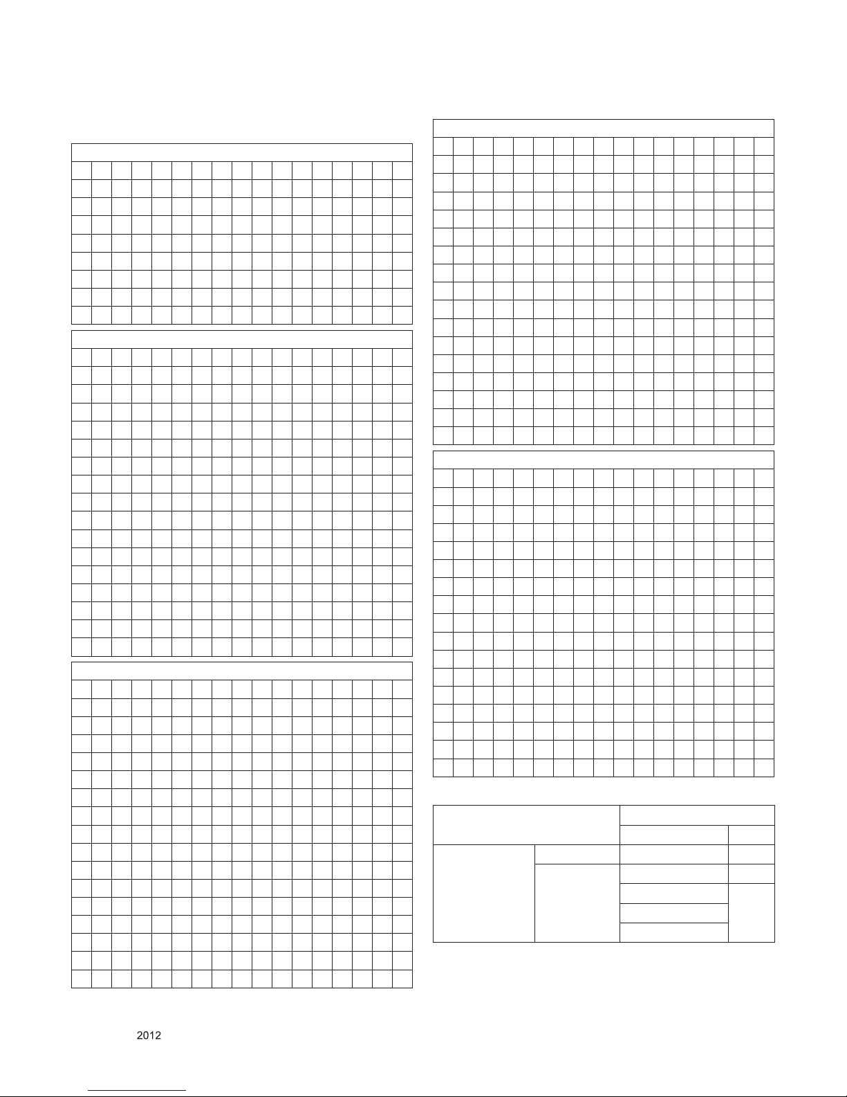
4.5.4. EDID data
4.5.4.1. Non-3D Full HD model (LS5700)
** Analog(RGB): 128bytes
0 1 2 3 4 5 6 7 8 9 A B C D E F
0 00 FF FF FF FF FF FF 00 1E 6D 01 00 01 01 01 01
10 01 16 01 03 68 A0 5A 78 0A EE 91 A3 54 4C 99 26
20 0F 50 54 A1 08 00 31 40 45 40 61 40 71 40 81 80
30 01 01 01 01 01 01 02 3A 80 18 71 38 2D 40 58 2C
40 45 00 A0 5A 00 00 00 1E 66 21 50 B0 51 00 1B 30
50 40 70 36 00 A0 5A 00 00 00 1E 00 00 00 FD 00 3A
60 3E 1E 53 10 00 0A 20 20 20 20 20 20 00 00 00 FC
70 00 4C 47 20 54 56 0A 20 20 20 20 20 20 20 00 5C
** HDMI 1 : 256Bytes
0 1 2 3 4 5 6 7 8 9 A B C D E F
0 00 FF FF FF FF FF FF 00 1E 6D 01 00 01 01 01 01
10 01 16 01 03 80 A0 5A 78 0A EE 91 A3 54 4C 99 26
20 0F 50 54 A1 08 00 31 40 45 40 61 40 71 40 81 80
30 01 01 01 01 01 01 02 3A 80 18 71 38 2D 40 58 2C
40 45 00 A0 5A 00 00 00 1E 66 21 50 B0 51 00 1B 30
50 40 70 36 00 A0 5A 00 00 00 1E 00 00 00 FD 00 3A
60 3E 1E 53 10 00 0A 20 20 20 20 20 20 00 00 00 FC
70 00 4C 47 20 54 56 0A 20 20 20 20 20 20 20 01 43
80 02 03 26 F1 4E 10 9F 04 13 05 14 03 02 12 20 21
90 22 15 01 26 15 07 50 09 57 07 67 03 0C 00 10 00
A0 B8 2D E3 05 00 00 01 1D 80 18 71 1C 16 20 58 2C
B0 25 00 A0 5A 00 00 00 9E 01 1D 00 80 51 D0 1A 20
C0 6E 88 55 00 A0 5A 00 00 00 1A 02 3A 80 18 71 38
D0 2D 40 58 2C 45 00 A0 5A 00 00 00 1E 66 21 50 B0
E0 51 00 1B 30 40 70 36 00 A0 5A 00 00 00 1E 00 00
F0 00 00 00 00 00 00 00 00 00 00 00 00 00 00 00
DD
** HDMI 2 : 256Bytes
0 1 2 3 4 5 6 7 8 9 A B C D E F
0 00 FF FF FF FF FF FF 00 1E 6D 01 00 01 01 01 01
10 01 16 01 03 80 A0 5A 78 0A EE 91 A3 54 4C 99 26
20 0F 50 54 A1 08 00 31 40 45 40 61 40 71 40 81 80
30 01 01 01 01 01 01 02 3A 80 18 71 38 2D 40 58 2C
40 45 00 A0 5A 00 00 00 1E 66 21 50 B0 51 00 1B 30
50 40 70 36 00 A0 5A 00 00 00 1E 00 00 00 FD 00 3A
60 3E 1E 53 10 00 0A 20 20 20 20 20 20 00 00 00 FC
70 00 4C 47 20 54 56 0A 20 20 20 20 20 20 20 01 43
80 02 03 26 F1 4E 10 9F 04 13 05 14 03 02 12 20 21
90 22 15 01 26 15 07 50 09 57 07 67 03 0C 00 20 00
A0 B8 2D E3 05 00 00 01 1D 80 18 71 1C 16 20 58 2C
B0 25 00 A0 5A 00 00 00 9E 01 1D 00 80 51 D0 1A 20
C0 6E 88 55 00 A0 5A 00 00 00 1A 02 3A 80 18 71 38
D0 2D 40 58 2C 45 00 A0 5A 00 00 00 1E 66 21 50 B0
E0 51 00 1B 30 40 70 36 00 A0 5A 00 00 00 1E 00 00
F0 00 00 00 00 00 00 00 00 00 00 00 00 00 00 00
CD
** HDMI 3 : 256Bytes
0 1 2 3 4 5 6 7 8 9 A B C D E F
0 00 FF FF FF FF FF FF 00 1E 6D 01 00 01 01 01 01
10 01 16 01 03 80 A0 5A 78 0A EE 91 A3 54 4C 99 26
20 0F 50 54 A1 08 00 31 40 45 40 61 40 71 40 81 80
30 01 01 01 01 01 01 02 3A 80 18 71 38 2D 40 58 2C
40 45 00 A0 5A 00 00 00 1E 66 21 50 B0 51 00 1B 30
50 40 70 36 00 A0 5A 00 00 00 1E 00 00 00 FD 00 3A
60 3E 1E 53 10 00 0A 20 20 20 20 20 20 00 00 00 FC
70 00 4C 47 20 54 56 0A 20 20 20 20 20 20 20 01 43
80 02 03 26 F1 4E 10 9F 04 13 05 14 03 02 12 20 21
90 22 15 01 26 15 07 50 09 57 07 67 03 0C 00 30 00
A0 B8 2D E3 05 00 00 01 1D 80 18 71 1C 16 20 58 2C
B0 25 00 A0 5A 00 00 00 9E 01 1D 00 80 51 D0 1A 20
C0 6E 88 55 00 A0 5A 00 00 00 1A 02 3A 80 18 71 38
D0 2D 40 58 2C 45 00 A0 5A 00 00 00 1E 66 21 50 B0
E0 51 00 1B 30 40 70 36 00 A0 5A 00 00 00 1E 00 00
F0 00 00 00 00 00 00 00 00 00 00 00 00 00 00 00
BD
** HDMI 3 : 256Bytes
0 1 2 3 4 5 6 7 8 9 A B C D E F
0 00 FF FF FF FF FF FF 00 1E 6D 01 00 01 01 01 01
10 01 16 01 03 80 A0 5A 78 0A EE 91 A3 54 4C 99 26
20 0F 50 54 A1 08 00 31 40 45 40 61 40 71 40 81 80
30 01 01 01 01 01 01 02 3A 80 18 71 38 2D 40 58 2C
40 45 00 A0 5A 00 00 00 1E 66 21 50 B0 51 00 1B 30
50 40 70 36 00 A0 5A 00 00 00 1E 00 00 00 FD 00 3A
60 3E 1E 53 10 00 0A 20 20 20 20 20 20 00 00 00 FC
70 00 4C 47 20 54 56 0A 20 20 20 20 20 20 20 01 43
80 02 03 26 F1 4E 10 9F 04 13 05 14 03 02 12 20 21
90 22 15 01 26 15 07 50 09 57 07 67 03 0C 00 40 00
A0 B8 2D E3 05 00 00 01 1D 80 18 71 1C 16 20 58 2C
B0 25 00 A0 5A 00 00 00 9E 01 1D 00 80 51 D0 1A 20
C0 6E 88 55 00 A0 5A 00 00 00 1A 02 3A 80 18 71 38
D0 2D 40 58 2C 45 00 A0 5A 00 00 00 1E 66 21 50 B0
E0 51 00 1B 30 40 70 36 00 A0 5A 00 00 00 1E 00 00
F0 00 00 00 00 00 00 00 00 00 00 00 00 00 00 00
AD
(Bold character)Checksum: Changeable by total EDID data.
EDID C/S data
8bit FHD
HDMI RGB
check sum (Hex) Block 0 0x43 RGB
Block 1 0xDD (HDMI1) 0x5C
0xCD (HDMI2)
0XBD (HDMI3)
0XAD (HDMI4)

- 14 -
LGE Internal Use OnlyCopyright © LG Electronics. Inc. All rights reserved.
Only for training and service purposes
4.5.4.2. 3D model _ Non XvYcc model (60/T120)
** Analog(RGB): 128bytes
0 1 2 3 4 5 6 7 8 9 A B C D E F
0 00 FF FF FF FF FF FF 00 1E 6D 01 00 01 01 01 01
10 01 16 01 03 68 A0 5A 78 0A EE 91 A3 54 4C 99 26
20 0F 50 54 A1 08 00 31 40 45 40 61 40 71 40 81 80
30 01 01 01 01 01 01 02 3A 80 18 71 38 2D 40 58 2C
40 45 00 A0 5A 00 00 00 1E 66 21 50 B0 51 00 1B 30
50 40 70 36 00 A0 5A 00 00 00 1E 00 00 00 FD 00 3A
60 3E 1E 53 10 00 0A 20 20 20 20 20 20 00 00 00 FC
70 00 4C 47 20 54 56 0A 20 20 20 20 20 20 20 00 5C
** HDMI 1 : 256Bytes
0 1 2 3 4 5 6 7 8 9 A B C D E F
0 00 FF FF FF FF FF FF 00 1E 6D 01 00 01 01 01 01
10 01 16 01 03 68 A0 5A 78 0A EE 91 A3 54 4C 99 26
20 0F 50 54 A1 08 00 31 40 45 40 61 40 71 40 81 80
30 01 01 01 01 01 01 02 3A 80 18 71 38 2D 40 58 2C
40 45 00 A0 5A 00 00 00 1E 66 21 50 B0 51 00 1B 30
50 40 70 36 00 A0 5A 00 00 00 1E 00 00 00 FD 00 3A
60 3E 1E 53 10 00 0A 20 20 20 20 20 20 00 00 00 FC
70 00 4C 47 20 54 56 0A 20 20 20 20 20 20 20 00 5C
80 00 FF FF FF FF FF FF 00 1E 6D 01 00 01 01 01 01
90 01 16 01 03 68 A0 5A 78 0A EE 91 A3 54 4C 99 26
A0 0F 50 54 A1 08 00 31 40 45 40 61 40 71 40 81 80
B0 01 01 01 01 01 01 02 3A 80 18 71 38 2D 40 58 2C
C0 45 00 A0 5A 00 00 00 1E 66 21 50 B0 51 00 1B 30
D0 40 70 36 00 A0 5A 00 00 00 1E 00 00 00 FD 00 3A
E0 3E 1E 53 10 00 0A 20 20 20 20 20 20 00 00 00 FC
F0 00 4C 47 20 54 56 0A 20 20 20 20 20 20 20 00
5C
** HDMI 2 : 256Bytes
0 1 2 3 4 5 6 7 8 9 A B C D E F
0 00 FF FF FF FF FF FF 00 1E 6D 01 00 01 01 01 01
10 01 16 01 03 80 A0 5A 78 0A EE 91 A3 54 4C 99 26
20 0F 50 54 A1 08 00 31 40 45 40 45 40 71 40 81 80
30 01 01 01 01 01 01 02 3A 80 18 71 38 2D 40 58 2C
40 45 00 A0 5A 00 00 00 1E 66 21 50 B0 51 00 1B 30
50 40 70 36 00 A0 5A 00 00 00 1E 00 00 00 FD 00 3A
60 3E 1E 53 10 00 0A 20 20 20 20 20 20 00 00 00 FC
70 00 4C 47 20 54 56 0A 20 20 20 20 20 20 20 01 43
80 02 03 37 F1 4E 10 9F 04 13 05 14 03 02 12 20 21
90 22 15 01 26 15 07 50 09 57 07 78 03 0C 00 20 00
A0 B8 2D 20 C0 0E 01 4F 3F FC 08 10 18 10 06 10 16
B0 10 28 10 E3 05 03 01 02 3A 80 18 71 38 2D 40 58
C0 2C 45 00 A0 5A 00 00 00 1E 01 1D 80 18 71 1C 16
D0 20 58 2C 25 00 A0 5A 00 00 00 9E 01 1D 00 72 51
E0 D0 1E 20 6E 28 55 00 A0 5A 00 00 00 1E 00 00 00
F0 00 00 00 00 00 00 00 00 00 00 00 00 00 00 00
05
** HDMI 3 : 256Bytes
0 1 2 3 4 5 6 7 8 9 A B C D E F
0 00 FF FF FF FF FF FF 00 1E 6D 01 00 01 01 01 01
10 01 16 01 03 80 A0 5A 78 0A EE 91 A3 54 4C 99 26
20 0F 50 54 A1 08 00 31 40 45 40 45 40 71 40 81 80
30 01 01 01 01 01 01 02 3A 80 18 71 38 2D 40 58 2C
40 45 00 A0 5A 00 00 00 1E 66 21 50 B0 51 00 1B 30
50 40 70 36 00 A0 5A 00 00 00 1E 00 00 00 FD 00 3A
60 3E 1E 53 10 00 0A 20 20 20 20 20 20 00 00 00 FC
70 00 4C 47 20 54 56 0A 20 20 20 20 20 20 20 01 43
80 02 03 37 F1 4E 10 9F 04 13 05 14 03 02 12 20 21
90 22 15 01 26 15 07 50 09 57 07 78 03 0C 00 30 00
A0 B8 2D 20 C0 0E 01 4F 3F FC 08 10 18 10 06 10 16
B0 10 28 10 E3 05 03 01 02 3A 80 18 71 38 2D 40 58
C0 2C 45 00 A0 5A 00 00 00 1E 01 1D 80 18 71 1C 16
D0 20 58 2C 25 00 A0 5A 00 00 00 9E 01 1D 00 72 51
E0 D0 1E 20 6E 28 55 00 A0 5A 00 00 00 1E 00 00 00
F0 00 00 00 00 00 00 00 00 00 00 00 00 00 00 00
F5
** HDMI 3 : 256Bytes
0 1 2 3 4 5 6 7 8 9 A B C D E F
0 00 FF FF FF FF FF FF 00 1E 6D 01 00 01 01 01 01
10 01 16 01 03 80 A0 5A 78 0A EE 91 A3 54 4C 99 26
20 0F 50 54 A1 08 00 31 40 45 40 45 40 71 40 81 80
30 01 01 01 01 01 01 02 3A 80 18 71 38 2D 40 58 2C
40 45 00 A0 5A 00 00 00 1E 66 21 50 B0 51 00 1B 30
50 40 70 36 00 A0 5A 00 00 00 1E 00 00 00 FD 00 3A
60 3E 1E 53 10 00 0A 20 20 20 20 20 20 00 00 00 FC
70 00 4C 47 20 54 56 0A 20 20 20 20 20 20 20 01 43
80 02 03 37 F1 4E 10 9F 04 13 05 14 03 02 12 20 21
90 22 15 01 26 15 07 50 09 57 07 78 03 0C 00 40 00
A0 B8 2D 20 C0 0E 01 4F 3F FC 08 10 18 10 06 10 16
B0 10 28 10 E3 05 03 01 02 3A 80 18 71 38 2D 40 58
C0 2C 45 00 A0 5A 00 00 00 1E 01 1D 80 18 71 1C 16
D0 20 58 2C 25 00 A0 5A 00 00 00 9E 01 1D 00 72 51
E0 D0 1E 20 6E 28 55 00 A0 5A 00 00 00 1E 00 00 00
F0 00 00 00 00 00 00 00 00 00 00 00 00 00 00 00
E5
(Bold character)Checksum: Changeable by total EDID data.
EDID C/S data
8bit FHD
HDMI RGB
check sum (Hex) Block 0 0x43 RGB
Block 1 0x15 (HDMI1) 0x5C
0x05 (HDMI2)
0xF5 (HDMI3)
0xE5 (HDMI4)
- 15 -
LGE Internal Use OnlyCopyright © LG Electronics. Inc. All rights reserved.
Only for training and service purposes
4.5.4.3. 3D model _XvYcc model (LM7600, 65LM6200)
** Analog(RGB): 128bytes
0 1 2 3 4 5 6 7 8 9 A B C D E F
0 00 FF FF FF FF FF FF 00 1E 6D 01 00 01 01 01 01
10 01 16 01 03 68 A0 5A 78 0A EE 91 A3 54 4C 99 26
20 0F 50 54 A1 08 00 31 40 45 40 61 40 71 40 81 80
30 01 01 01 01 01 01 02 3A 80 18 71 38 2D 40 58 2C
40 45 00 A0 5A 00 00 00 1E 66 21 50 B0 51 00 1B 30
50 40 70 36 00 A0 5A 00 00 00 1E 00 00 00 FD 00 3A
60 3E 1E 53 10 00 0A 20 20 20 20 20 20 00 00 00 FC
70 00 4C 47 20 54 56 0A 20 20 20 20 20 20 20 00 5C
** HDMI 1 : 256Bytes
0 1 2 3 4 5 6 7 8 9 A B C D E F
0 00 FF FF FF FF FF FF 00 1E 6D 01 00 01 01 01 01
10 01 16 01 03 80 A0 5A 78 0A EE 91 A3 54 4C 99 26
20 0F 50 54 A1 08 00 31 40 45 40 45 40 71 40 81 80
30 01 01 01 01 01 01 02 3A 80 18 71 38 2D 40 58 2C
40 45 00 A0 5A 00 00 00 1E 66 21 50 B0 51 00 1B 30
50 40 70 36 00 A0 5A 00 00 00 1E 00 00 00 FD 00 3A
60 3E 1E 53 10 00 0A 20 20 20 20 20 20 00 00 00 FC
70 00 4C 47 20 54 56 0A 20 20 20 20 20 20 20 01 43
80 02 03 37 F1 4E 10 9F 04 13 05 14 03 02 12 20 21
90 22 15 01 26 15 07 50 09 57 07 78 03 0C 00 10 00
A0 B8 2D 20 C0 0E 01 4F 3F FC 08 10 18 10 06 10 16
B0 10 28 10 E3 05 03 01 02 3A 80 18 71 38 2D 40 58
C0 2C 45 00 A0 5A 00 00 00 1E 01 1D 80 18 71 1C 16
D0 20 58 2C 25 00 A0 5A 00 00 00 9E 01 1D 00 72 51
E0 D0 1E 20 6E 28 55 00 A0 5A 00 00 00 1E 00 00 00
F0 00 00 00 00 00 00 00 00 00 00 00 00 00 00 00
11
** HDMI 2 : 256Bytes
0 1 2 3 4 5 6 7 8 9 A B C D E F
0 00 FF FF FF FF FF FF 00 1E 6D 01 00 01 01 01 01
10 01 16 01 03 80 A0 5A 78 0A EE 91 A3 54 4C 99 26
20 0F 50 54 A1 08 00 31 40 45 40 45 40 71 40 81 80
30 01 01 01 01 01 01 02 3A 80 18 71 38 2D 40 58 2C
40 45 00 A0 5A 00 00 00 1E 66 21 50 B0 51 00 1B 30
50 40 70 36 00 A0 5A 00 00 00 1E 00 00 00 FD 00 3A
60 3E 1E 53 10 00 0A 20 20 20 20 20 20 00 00 00 FC
70 00 4C 47 20 54 56 0A 20 20 20 20 20 20 20 01 43
80 02 03 37 F1 4E 10 9F 04 13 05 14 03 02 12 20 21
90 22 15 01 26 15 07 50 09 57 07 78 03 0C 00 20 00
A0 B8 2D 20 C0 0E 01 4F 3F FC 08 10 18 10 06 10 16
B0 10 28 10 E3 05 03 01 02 3A 80 18 71 38 2D 40 58
C0 2C 45 00 A0 5A 00 00 00 1E 01 1D 80 18 71 1C 16
D0 20 58 2C 25 00 A0 5A 00 00 00 9E 01 1D 00 72 51
E0 D0 1E 20 6E 28 55 00 A0 5A 00 00 00 1E 00 00 00
F0 00 00 00 00 00 00 00 00 00 00 00 00 00 00 00
01
** HDMI 3 : 256Bytes
0 1 2 3 4 5 6 7 8 9 A B C D E F
0 00 FF FF FF FF FF FF 00 1E 6D 01 00 01 01 01 01
10 01 16 01 03 80 A0 5A 78 0A EE 91 A3 54 4C 99 26
20 0F 50 54 A1 08 00 31 40 45 40 45 40 71 40 81 80
30 01 01 01 01 01 01 02 3A 80 18 71 38 2D 40 58 2C
40 45 00 A0 5A 00 00 00 1E 66 21 50 B0 51 00 1B 30
50 40 70 36 00 A0 5A 00 00 00 1E 00 00 00 FD 00 3A
60 3E 1E 53 10 00 0A 20 20 20 20 20 20 00 00 00 FC
70 00 4C 47 20 54 56 0A 20 20 20 20 20 20 20 01 43
80 02 03 37 F1 4E 10 9F 04 13 05 14 03 02 12 20 21
90 22 15 01 26 15 07 50 09 57 07 78 03 0C 00 30 00
A0 B8 2D 20 C0 0E 01 4F 3F FC 08 10 18 10 06 10 16
B0 10 28 10 E3 05 03 01 02 3A 80 18 71 38 2D 40 58
C0 2C 45 00 A0 5A 00 00 00 1E 01 1D 80 18 71 1C 16
D0 20 58 2C 25 00 A0 5A 00 00 00 9E 01 1D 00 72 51
E0 D0 1E 20 6E 28 55 00 A0 5A 00 00 00 1E 00 00 00
F0 00 00 00 00 00 00 00 00 00 00 00 00 00 00 00
F1
** HDMI 3 : 256Bytes
0 1 2 3 4 5 6 7 8 9 A B C D E F
0 00 FF FF FF FF FF FF 00 1E 6D 01 00 01 01 01 01
10 01 16 01 03 80 A0 5A 78 0A EE 91 A3 54 4C 99 26
20 0F 50 54 A1 08 00 31 40 45 40 45 40 71 40 81 80
30 01 01 01 01 01 01 02 3A 80 18 71 38 2D 40 58 2C
40 45 00 A0 5A 00 00 00 1E 66 21 50 B0 51 00 1B 30
50 40 70 36 00 A0 5A 00 00 00 1E 00 00 00 FD 00 3A
60 3E 1E 53 10 00 0A 20 20 20 20 20 20 00 00 00 FC
70 00 4C 47 20 54 56 0A 20 20 20 20 20 20 20 01 43
80 02 03 37 F1 4E 10 9F 04 13 05 14 03 02 12 20 21
90 22 15 01 26 15 07 50 09 57 07 78 03 0C 00 40 00
A0 B8 2D 20 C0 0E 01 4F 3F FC 08 10 18 10 06 10 16
B0 10 28 10 E3 05 03 01 02 3A 80 18 71 38 2D 40 58
C0 2C 45 00 A0 5A 00 00 00 1E 01 1D 80 18 71 1C 16
D0 20 58 2C 25 00 A0 5A 00 00 00 9E 01 1D 00 72 51
E0 D0 1E 20 6E 28 55 00 A0 5A 00 00 00 1E 00 00 00
F0 00 00 00 00 00 00 00 00 00 00 00 00 00 00 00
E1
(Bold character)Checksum: Changeable by total EDID data.
EDID C/S data
8bit FHD
HDMI RGB
check sum (Hex) Block 0 0x43 RGB
Block 1 0x11 (HDMI1) 0x5C
0x01 (HDMI2)
0xF1 (HDMI3)
0xE1 (HDMI4)

- 16 -
LGE Internal Use OnlyCopyright © LG Electronics. Inc. All rights reserved.
Only for training and service purposes
4.5. ADC Calibration : Comp 480i/Comp 1080p/RGB
4.5.1. ADC Calibration : Internal Auto ADC
1) Press “ADJ” key on R/C for adjustment.
2) Enter Password number. Password is “0 0 0 0”.
3) Move to the “8. ADC Calibration” by using ▲/▼(CH +/-) and
press ENTER(►).
4) Move to the “ADC Type” by using ▲/▼(CH +/-)
5) Press the right direction key(►) to ADC Type “OTP”.
6) Press the right direction key(►) to Start.
7) After about a few seconds, appear “ADC Calibration
Completed”, then complete
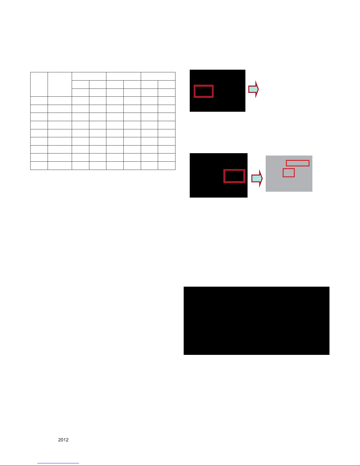
4.5.2. ADC Calibration - Manual
※ Required Equipments
▪ Remote controller for adjustment
▪ MSPG-925F/MSPG-1025/MSPG-3233 Pattern Generator
4.5.2.1. Process
1) Change the Input to Component1 or 2 mode..
2) Input the Component 480i@60Hz 100% Color Bar YPbPr
signal into Component1 or 2.
(MSPG-925F 480i Model: 209 / Pattern: 65 )
(MSPG-925F 1080p Model: 225 / Pattern: 65 )
[Fig. 2]
3) Press “ADJ” key on R/C for adjustment.
4) Enter Password number. Password is “0 0 0 0”.
5) Move to the “8. ADC Calibration” by using ▲/▼(CH +/-) and
press ENTER(►).
6) Move to the “ADC Type” by using ▲/▼(CH +/-)
7) Press the right direction key(►) to ADC Type “External”.
8) Press the right direction key(►) to Start.
9) After about a few seconds, appear “ADC Calibr ati on
Completed”, then complete.
10) Change input source component 1080p, Do 3)~9) steps.
11) Change input source RGB 1080p and Do 3)~9) steps.
4.6. Check SW Version
4.6.1. Method
1) Push In-star key on Adjust remote-controller.
2) SW Version check(ex. 47LW9800-DA)
5. SET assembly adjustment method
5.1. Input Area-Option
(1) Prole : Must be changed the Area option value because
being different of each Country’s Language and
signal Condition.
(2) Equipment : adjustment remote control.
(3) Adjustment method
- The input methods are same as other chassis.(Use IN-START
Key on the Adjust Remocon.)
Refer to Job Expression of each main chassis ass’y
(EBTxxxxxxxx) for Option value
5.2. Adjustment of White Balance
● In case of keeping module is in the circumstance of 0°C, it
should be placed in the circumstance of above 15°C for 2
hours
● In case of keeping module is in the circumstance of below
-20°C, it should be placed in the circumstance of above 15°C
for 3 hours.
IN START
Model Name : 47LW9800-DA
1.Adjust Check ▶
Adjust Check
Serial Number : 012PTED6N500 2.ADC Date 1. Co untry Group(Press OK to Save)
S/W Version : 3.02.06.01 3.Power Off Status Country Group Code 10
MICOM Version : 3.05.3 4.System1 Coun try Group TW
BOOT Version : 1.02.22 5.System2 Country TW/CB/PA
FRC Version : 1.50 6.Model Number D/L 2. Tool Option
IR LED Version : c8 7.Test Option Tool Option1 33112
EDID(RGB/HDMI) : 0.03/0.02 8.External ADC To ol Option2 5461
Chip Type : BCM35230 9.Spread Spectrum Tool Option3 3327
Wireless Host Ver. : 0.00.0 10.Sync Level Tool Option4 17593
Wireless B/B Ver. : 0.00.0 11.Wireless Ready Tool Option5 47695
Wi-Fi Version :1.0 12.Stable Count Tool Opt ion6 697
Wi-Fi Channel :0 13.ODC Test 3. Adj ust White Balance : OK
Wi-Fi MAC :00:00:00:00:00:00 14.Local Dimming 4. Adjust ADC : OTP
MAC Address :FF:FF:FF:FF:FF:FF 15.SDP Server Selection 480i Compon ent OK
Widevine :LGTV10L000011618 16. Network Error History 1080p Component OK
Local Dimming Ver. :0x0707 RGB OK
Formatter Version : 0.6c 5.EDID : OK
RF Receiver Version : RGB OK(0x98)
Debug Status : Release HDMI1 OK(0x7F,0xCB)
HDMI2 OK(0x7F,0xBB)
UTT : 40 HDMI3 OK(0x7F,0xAB)
APP History Ver. : 35190 HDMI4 OK(0x7F,0x9B)
PQL DB : LGD_AF_LGT10_xxxxxx
- 17 -
LGE Internal Use OnlyCopyright © LG Electronics. Inc. All rights reserved.
Only for training and service purposes
▪ Purpose : Adjust the color temperature to reduce the deviation
of the module color temperature.
▪ Principle : To adjust the white balance without the saturation,
Fix the one of R/G/B gain to 192 (default data) and
decrease the others.
▪ Adjustment mode : Three modes – Cool / Medium / Warm
※ Required Equipment
▪ Remote controller for adjustment
▪ Color Analyzer : CA100+ or CA-210 or same product (should
be used in the calibrated ch by CS-1000)
- LCD TV : CH-9
- PDP TV : CH-10
- White LED TV : CH-14
- RGB LED(MNT) : CH-16
- Auto W/B adjustment instrument(only for Auto adjustment)
5.2.1. Adjustment of White Balance :
(For Automatic Adjustment)
Co nnectin g diagra m of eq uipment for meas uring (F or
Automatic Adjustment)
1) Set TV in adj. mode using POWER ON key
2) Zero calibrate probe then place it on the center of the
Display
3) Connect Cable(RS-232C)
4) Select mode in adj. Program and begin adj.
5) When adj. is complete (OK Sing), check adj. status pre
mode(Warm, Medium, Cool)
6) Remove probe and RS-232C cable to complete adj.
▪ W/B Adj. must begin as start command “wb 00 00” , and
finish as end command “wb 00 ff”, and Adj. offset if need
※ Luminance min value is 150cd in the Cool/Medium/Warm
mode( For LCD)
5.2.2. Adjustment of White Balance (for Manual adjustment)
▪ Co lor analyzer(CA100+, CA210) should be used in the
calibrated ch by CS-1000
▪ Operate the zero-calibration of the CA100+ or CA-210, then
stick sensor to the module when adjusting.
▪ For manual adjustment, it is also possible by the following
sequence.
1) Select white pattern of heat-run by pressing “POWER ON”
key on remote control for adjustment then operate heat run
longer than 15 minutes.
(If not executed this step, the condition for W/B may be
different.)
2) Push “Exit” key.
3) Change to the AV mode by remote control.
4) Input external pattern (80% white pattern)
5) Push the ADJ key => Enter “0000” (Password)
6) Select “3. W/B ADJUST”
7) Enter the W/B ADJUST Mode
8) Stick the sensor to the center of the screen and select each
items (Red/Green/Blue Gain and Offset) using ▲/▼(CH +/-)
key on R/C..
9) Adjust R/ G/ B Gain using ◄/►(VOL +/-) key on R/C.
10) Adjust three modes all (Cool / Medium / Warm) : Fix the
one of R/G/B gain and change the others
11) When adjustment is completed, Enter “COPY ALL”
12) Exit adjustment mode using EXIT key on R/C.
※ CASE
First adjust the coordinate far away from the target value(x, y).
(1) x, y >target
i) Decrease the R, G.
(2) x, y < target
i) First decrease the B gain,
ii) Decrease the one of the others.
(3) x >target , y< target
i) First decrease B, so make y a little more than the target.
ii) Adjust x value by decreasing the R
(4) x < target , y >target
i) First decrease B, so make x a little more than the target.
ii) Adjust x value by decreasing the G
● Standard color coordinate and temperature when using the
CA100+ or CA210 equipment
Change reason : When vivid mode, more detail than other
company set.
Color coordinate
Mode
X Y
Temp
△uv
Cool
0.269±0.002 0.273±0.002 13000K
0.0000
Medium 0.285±0.002 0.293±0.002 9,300 K 0.000
Warm 0.313±0.002 0.329±0.002 6,500K 0.003
- 18 -
LGE Internal Use OnlyCopyright © LG Electronics. Inc. All rights reserved.
Only for training and service purposes
● In case of Edge LED module, the color coordinates is
changing by aging, so you have to use the below table.
The Time Table of color coordinates by SET Aging Time
GP3 Aging
time
(Min)
Cool Medium Warm
x y x y x y
269 273 285 293 313 329
1 0 ~ 2 279 288 295 308 319 338
2 3 ~ 5 278 286 294 306 318 336
3 6 ~ 9 277 285 293 305 317 335
4 10 ~19 276 283 292 303 316 333
5 20 ~ 35 274 280 290 300 314 330
6 36 ~ 49 272 277 288 297 312 327
7 50 ~ 79 271 275 287 295 311 325
8 80 ~ 149 270 274 286 294 310 324
9 Over 150 269 273 285 293 309 323
■ In the SET applied LED module (LS5700/LM6200/LM6600/
LM7600 Series), cause of the physical characteristics of
LED Module, sets are taken a 120 minutes by aging time
to stabilize a color coordinates. So White Balance Control
equipments have to get the SET Aging Time from the SET
and then going to control the W/B by revise color coordinates
at each time
- To check the Coordinates of White Balance, you have to
measure at the below conditions.
Picture Mode : select Vivid and change
Dynamic Contrast : Off ,
Dynamic Colour : Off,
Clear White : Off
->Picture Mode change : Vidid -> Vivid(User)
(If you miss the upper condition, the coordinates of W/B can be
lower than the spec.)
5.3. Intelligent Sensor Inspection Guide
Step 1. Turn on the TV set.
Step 2. Press “EYE” button on the Adjustment remote controller.
Step 3. Block the Intelligent Sensor module on the front C/A
about 6 seconds.
When the “Sensor Data” is lower than 20, you can see the
“OK” message -> If it doesn’t show “OK” message, the Sensor
Module is defected one.
You have to replace that with a good one.
Step 4. After check the “OK” message come out, take out your
hand from the Sensor module.
-> Check “Sensor Data” value change from “0” to “300” or not.
If it doesn’t change the value, the sensor is also defected
one. You have to replace it.
5.4. LAN Inspection
1) LAN Port connection with PCB
2) Network setting at MENU Mode of TV
3) Setting automatic IP
4) Setting state conrmation
5) If automatic setting is nished, you conrm IP and MAC
Address
Green Eye-Check
Sensor Data : 492
BackLight : 100
OK
- 19 -
LGE Internal Use OnlyCopyright © LG Electronics. Inc. All rights reserved.
Only for training and service purposes
5.5. WIDEVINE Key Inspection
1) Conrm Key input Data at the “IN START” MENU Mode
5.6. Model name & Serial number D/L
5.6.1. Notice
1) Serial number D/L is using of scan equipment.
2) Setting of scan equipment operated by Manufacturing
Technology Group.
3) Serial number D/L must be conformed when it is produced in
production line, because serial number D/L is mandatory by
D-book 4.0
4) Check the model name In-start menu -> Factory name
displayed (ex 32LS5700-DA)
5) Check the Diagnostics (DTV country only) -> Buyer model
displayed (ex 32LS5700-DA)
5.6.2. Method : Auto
1) Press “Power on” key of service remocon.(Baud rate : 115200
bps)
2) Connect RS232 Signal Cable to RS-232 Jack
3) Write Serial number by use RS-232.
4) Must check the serial number at Instart menu
5.6.3. Method : Manual
* If the TV set is downloaded By OTA or Service man, Sometimes
model name or serial number is initialized.
( Not always) It is impossible to download by bar code scan, so
It need Manual download.
1) Press the ‘instart’ key of ADJ remote controller.
2) Go to the menu ‘6.Model Number D/L’ like below photo.
3) Input the Factory model name or Serial number like photo.
5.7. Wi-Fi MAC ADDRESS CHECK
5.7.1. Notice
1) Using RS232
Command Set ACK
Transmission [A][l][][Set ID][][20][Cr] [O][K][x] or [N][G]
2) Check the menu on in-start
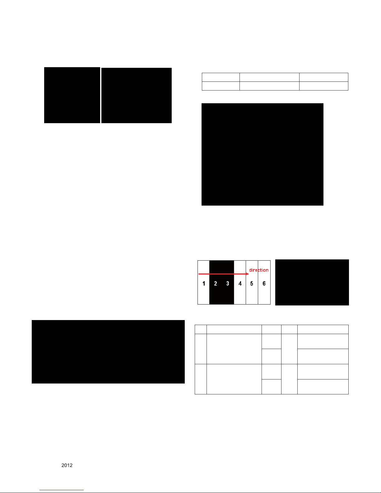
5.8. Local Dimming Inspection
5.8.1. Edge LED models with local dimming
1) Press ‘TILT” key of the Adj. R/C and check moving patterns. The black bar patterns moves from left to right. If local
dimming function does not work, a whole screen shows full
white.
5.9. Internal press test
No Item Vallue Unit Remark
1. Dielectric
Voltage(AC<->FG)
1.5 kV At 100mA for
1sec(Line)
1.5 At 100mA for
1min(OQC)
2. Dielectric
Voltage(Without FG)
3 kV At 100mA for
1sec(Line)
3 At 100mA for
1min(OQC)

- 20 -
LGE Internal Use OnlyCopyright © LG Electronics. Inc. All rights reserved.
Only for training and service purposes
5.10. Motion Remote controller Inspection
5.10.1. Equipment
Motion remote controller for test, IR-KEY-CODE remote
controller for test
Check battery before test. (Recommend : Change battery for
every Lot.)
5.10.2. Process
1) Push “Mute” or “ START” key for pairing between TV-set and
motion remote controller.
2) Push “OK” or “Enter” key, you can see the Cursor on screen.
3) Push “Vol+” or “STOP” key, Disconnect Pairing.
5.11. 3D Function test (EXCEPT : LS5700)
5.11.1. Equipment
Pattern Generator MSPG-3233, HDMI mode 37, pattern No. 81
5.11.2. Equipment
1) Connect HDMI (HDMI mode 371, Pattern No. 81)
2) Insert 3D Mode, Select side by side mode.
3) Without 3D-glasses, Like below gure.
4) With 3D left-glass, Like below gure. (Center is RED)
5) With 3Dright-glass, Like below gure.(Center is Blue)
- 21 -
LGE Internal Use OnlyCopyright © LG Electronics. Inc. All rights reserved.
Only for training and service purposes
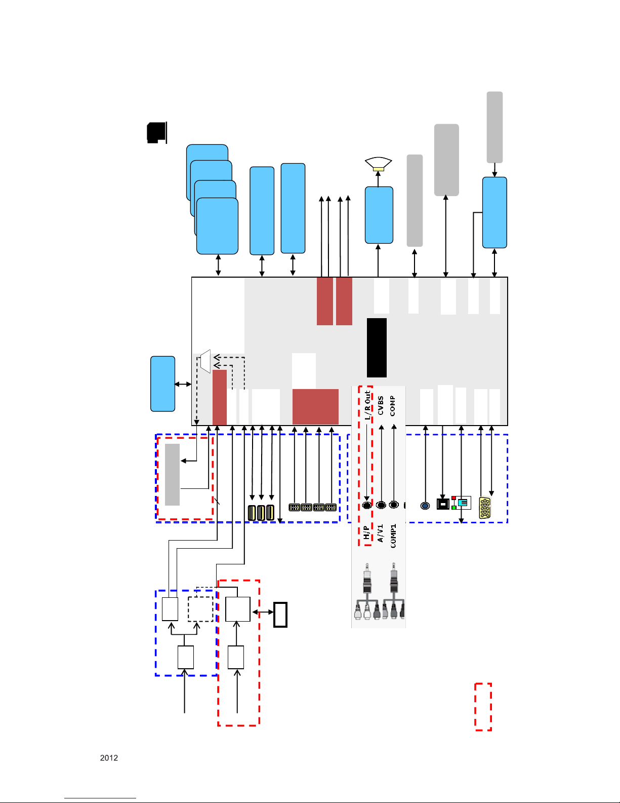
BLOCK DIAGRAM
MTK Block Diagram (Taiwan/Colombia/Panama)
Power load
L/R In
SPDIF OUT
USB
Audio
AMP
(NTP7500
or STA380)
I2S Out
MTK
CI slot
CI slot
P_TS
CVBS
P_TS
T/C Demod
IF(+/-)
USB1
PC-RGB
PC-AUDIO
OPTIC
LAN
HDMI1
HDMI2
HDMI3
Side
Rear
RGB,H/V
Ethernet
CVBS
UART
SYSTEM EEPROM X 1
(256Kb)
HDMI
MUX
(HDCP
EEPROM)
M-Remote Module
Air/
Cable
TUNER
(T/C)
TUNER
(S2)
DIGITAL
DEMOD
(T/C)
DVB-
S
ANALOG
DEMOD
DIGITAL
DEMOD
(S2)
TS_S/P
LNB
USB2
USB3
HDMI4
LVDS
41P
51P
eMMC X 1
(4GB)
USB_WIFI
DDR
CONTROLER A/B
SPI
LOCAL DIMMING
I2C
Sub Micom
(RENESAS)
IR
Remote Control
UART
P_TS
EPI
50P
50P
X_TAL
27MHz
: Spec Out
SYSTEM
DDR3 X 1600
X 16
(2Gb)
SYSTEM
DDR3 X 1600
X 16
(2Gb)
SYSTEM
DDR3 X 1600
X 16
(2Gb)
SYSTEM
DDR3 X 1600
X 16
(2Gb)

- 22 -
LGE Internal Use OnlyCopyright © LG Electronics. Inc. All rights reserved.
Only for training and service purposes
[SPDIF_OUT]
Main SoC
MTK
[Y1P],[PB1P],[PR1P]
[OPCTRL9]
[AL0_ADAC]
[AR0_ADAC]
[VGA_SCL]
[VGA_SDA]
[OPCTRL7]
[VSYNC], [HSYNC]
[RP],[GP],[BP]
SPDIF
SPDIF_OUT
[AIN2_L_AADC]
COMP 1 PHONE JACK
COMP1_Y/Pb/Pr
COMP1_DET
[AIN3_R_AADC]
[AIN3_L_AADC]
[CVBS0P]
[OPCTRL5]
CVBS 1 PHONE JACK
EARPHONE
JACK
HP_LOUT_MAIN
HP_ROUT_MAIN
RGB_PC
RGB_DDC_SCL
RGB_DDC_SDA
DSUB_DET
DSUB_VSYNC, DSUB_HSYNC
DSUB_R+, DSUB_G+, DSUB_B+
PC AUDIO
PC_L_IN
PC_R_IN
[AIN2_R_AADC]
Jack Interface
IC6100
TPA6132A2
HP_LOUT_AMP
HP_ROUT_AMP
AV1_L_IN
AV1_R_IN
AV1_CVBS_DET
AV1_CVBS_IN
- 23 -
LGE Internal Use OnlyCopyright © LG Electronics. Inc. All rights reserved.
Only for training and service purposes
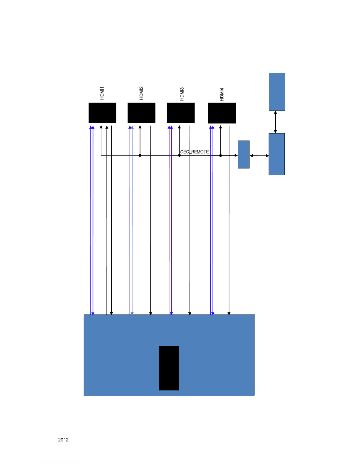
HDMI
HDMI1
HDMI1
HDMI2
HDMI2
HDMI3
HDMI3
HDMI4
HDMI4
CEC_REMOTE
RENESAS
MICOM
HDMI_CEC
Main SoC
MTK
Q3001
DDC_SCL_1_SOC
DDC_SCL_2_JACK
DDC_SDA_2_JACK
DDC_SCL_3_JACK
DDC_SDA_3_JACK
DDC_SCL_4_JACK
DDC_SDA_4_JACK
CK+/-_HDMI4_JACK, D0+/-_HDMI4_JACK, D1+/-_HD MI4_JACK, D2+/-_HDMI4_JACK
CK+/-_HDMI3_JACK, D0+/-_HDMI3_JACK, D1+/-_HD MI3_JACK, D2+/-_HDMI3_JACK
CK+/-_HDMI2_JACK, D0+/-_HDMI2_JACK, D1+/-_HD MI2_JACK, D2+/-_HDMI2_JACK
CK+/-_HDMI1_SOC, D0+/-_HDMI1_SOC, D1+/-_HDMI1_SOC , D2+/-_HDMI1_SOC
HDMI_ARC
[ASPDIF1]
[HDMI_2_SCL]
[HDMI_2_SDA]
[HDMI_2_RX_C/CB],HDMI_2_RX_0/0B]
[HDMI_2_RX_1/1B],[HDMI_2_RX_2/2B]
DDC_SDA_1_SOC
[CEC]
[HDMI_0_RX_C/CB],HDMI_0_RX_0/0B]
[HDMI_0_RX_1/1B],[HDMI_0_RX_2/2B]
[HDMI_1_RX_C/CB],HDMI_1_RX_0/0B]
[HDMI_1_RX_1/1B],[HDMI_1_RX_2/2B]
[HDMI_3_RX_C/CB],HDMI_3_RX_0/0B]
[HDMI_3_RX_1/1B],[HDMI_3_RX_2/2B]
[HDMI_0_SCL]
[HDMI_0_SDA]
[HDMI_1_SCL]
[HDMI_1_SDA]
[HDMI_3_SCL]
[HDMI_3_SDA]
X-tal
32.768kHz
- 24 -
LGE Internal Use OnlyCopyright © LG Electronics. Inc. All rights reserved.
Only for training and service purposes
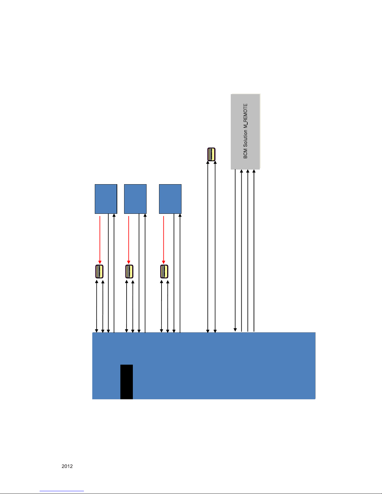
MTK
USB / WIFI / M-REMOTE
USB1
USB_DP1
USB_DM1
[USB_DP_P1]
[USB_DM_P2]
USB2
USB_DP2
USB_DM2
[GPIO43]
[GPIO46]
OCP
OCP
(+5V_USB_HDD)+0.3
(+5V_USB)+0.3
/SUB_OCD1
USB_CTL1
USB_CTL2
/USB_OCD2
USB_WIFI
WIFI_DM
WIFI_DP
BCM Solution M_REMOTE
BCM Solution M_REMOTE
M_REMOTE_RX
M_REMOTE_TX
M_RFModule_RESET
_M_REMOTE_ISP
[U1RX]
[U1TX]
[OPCTRL4]
[OPCTRL2]
[USB_DM_P2]
[USB_DP_P2]
USB_DP3
OCP
(+5V_USB)+0.3
USB_CTL3
/USB_OCD3
[USB_DM_P0]
[USB_DP_P0]
[GPIO42]
[GPIO45]
[USB_DM_P3]
[USB_DP_P3]
USB3
USB_DM3
[GPIO44]
[GPIO47]
- 25 -
LGE Internal Use OnlyCopyright © LG Electronics. Inc. All rights reserved.
Only for training and service purposes
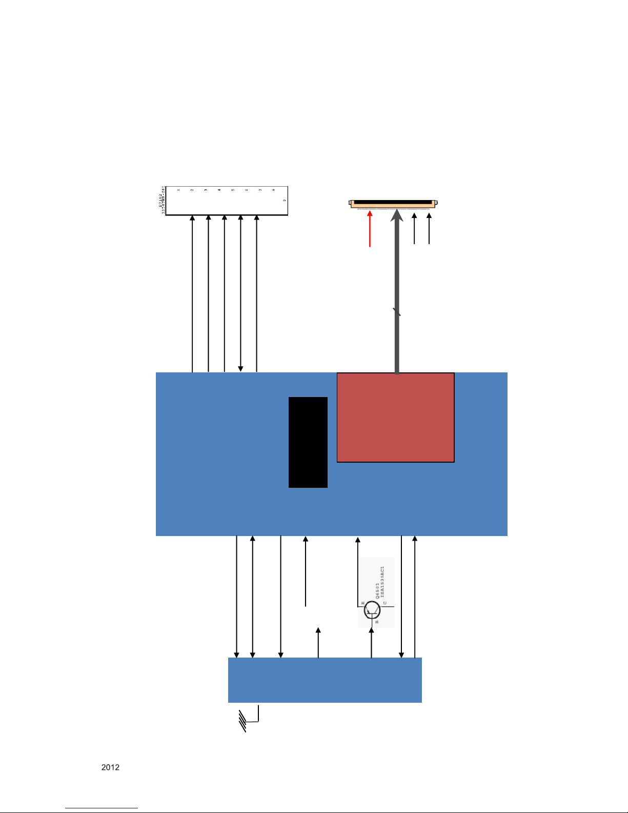
LVDS Tx
Block
Main SoC
MTK
LVDS_SEL
BIT_SEL_LOW
51Pin
LVDS
Output
PANEL_VCC
(+12V)
PANEL_VCC
(+12V)
10-bit (R)
Dual-link LVDS Output
24
• LVDS_SEL : “H”=JEIDA, “L” or NC=VESA (LGD)
• BIT_SEL : “H” or NC = 10-bit, “L” = 8-bit
TUNER/LVDS Tx (FHD120Hz)/LOCAL DIMMING
L/DIMO_SCLK
L/DIMO_MOSI
I2C_SCL1
I2C_SDA1
L/DIMO_VS
[LDM_CK]
[LDM_VSYNC]
[STB_SCL]
[LDM_D0]
[STB_SDA]
T /C_
H/NIM
I2C_SCL6
I2C_SDA6
/TU_RESET
TUNER_SIF
SIF
TU_CVBS
CVBS
IF_AGC
IF_P/N
- 26 -
LGE Internal Use OnlyCopyright © LG Electronics. Inc. All rights reserved.
Only for training and service purposes
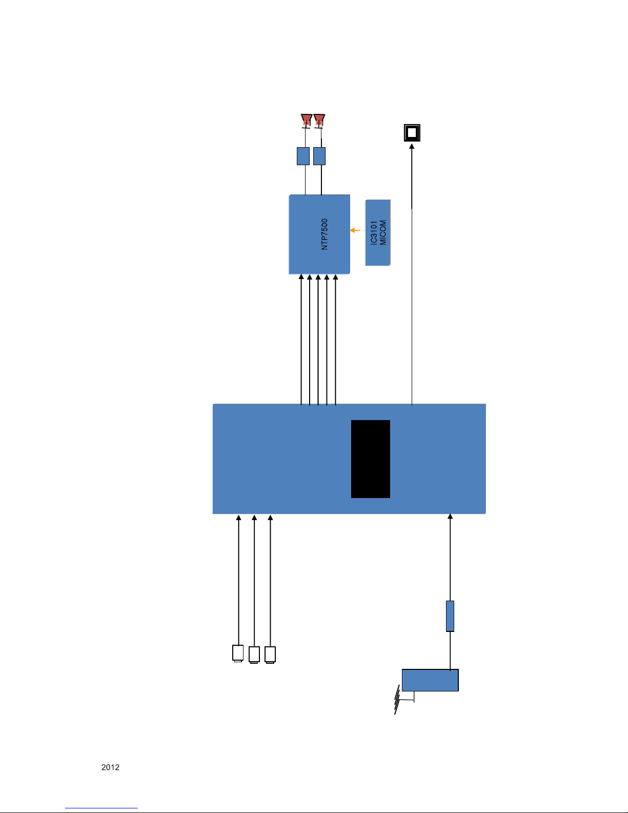
AUDIO
SPDIF_OUT
NTP7500
LPF
LPF
P
C_L_IN/PC_R_IN
AV1_L_IN/AV1_R_IN
[ASPDIF0]
Tuner
TR BUF
[SIFP]
SC_L_IN/SC_R_IN
AUD_LRCK
[AIN0_L_AADC]
[AIN0_R_AADC]
4P wafer
Main SoC
MTK
TUNER_SIF
[AOLRCK]
[AOSDATA0]
AUD_LRCH
AUD_SCK
[AOBCK]
[STB_SDA]
[STB_SCL]
I2C_SDA1
I2C_SCL1
IC3101
MICOM
AMP_MUTE
[AIN3_L_AADC]
[AIN3_R_AADC]
[AIN2_L_AADC]
[AIN2_R_AADC]
SPDIF

- 27 -
LGE Internal Use OnlyCopyright © LG Electronics. Inc. All rights reserved.
Only for training and service purposes
A2
A21
A10
AG1
900
300
200
400
540
521
530
800
810
710
700
910
120
510
501
500
* Set + Stand
* Stand Base + Body
LV1
LV2
122
123
522
EXPLODED VIEW
Many electrical and mechanical parts in this chassis have special safety-related characteristics. These
parts are identified by in the Schematic Diagram and EXPLODED VIEW.
It is essenti al that these special safet y parts shoul d be replac ed with the same compo nents as
recommended in this manual to prevent X-RADIATION, Shock, Fire, or other Hazards.
Do not modify the original design without permission of manufacturer.
IMPORTANT SAFETY NOTICE

- 2 -
LGE Internal Use OnlyCopyright © LG Electronics. Inc. All rights reserved.
Only for training and service purposes
CONTENTS
CONTENTS .............................................................................................. 2
PRODUCT SAFETY ................................................................................. 3
SPECIFICATION ....................................................................................... 4
ADJUSTMENT INSTRUCTION .............................................................. 10
BLOCK DIAGRAM .................................................................................. 21
EXPLODED VIEW .................................................................................. 27
SCHEMATIC CIRCUIT DIAGRAM ..............................................................
- 3 -
LGE Internal Use OnlyCopyright © LG Electronics. Inc. All rights reserved.
Only for training and service purposes
Many electrical and mechanical parts in this chassis have special safety-related characteristics. These parts are identified by in the
Schematic Diagram and Exploded View.
It is essential that these special safety parts should be replaced with the same components as recommended in this manual to prevent
Shock, Fire, or other Hazards.
Do not modify the original design without permission of manufacturer.
General Guidance
An isolation Transformer should always be used during the
servicing of a receiver whose chassis is not isolated from the AC
power line. Use a transformer of adequate power rating as this
protects the technician from accidents resulting in personal injury
from electrical shocks.
It will also protect the receiver and it's components from being
damaged by accidental shorts of th e cir cuitry that may be
inadvertently introduced during the service operation.
If any fuse (or Fusible Resistor) in this TV receiver is blown,
replace it with the specified.
When replacing a high wattage resistor (Oxide Metal Film Resistor,
over 1 W), keep the resistor 10 mm away from PCB.
Keep wires away from high voltage or high temperature parts.
Before returning the receiver to the customer,
always perform an AC leakage current check on the exposed
metallic parts of the cabinet, such as antennas, terminals, etc., to
be sure the set is safe to operate without damage of electrical
shock.
Leakage Current Cold Check(Antenna Cold Check)
With the instrument AC plug removed from AC source, connect an
electrical jumper across the two AC plug prongs. Place the AC
switch in the on position, connect one lead of ohm-meter to the AC
plug prongs tied together and touch other ohm-meter lead in turn to
each exposed metallic parts such as antenna terminals, phone
jacks, etc.
If the exposed metallic part has a return path to the chassis, the
measured resistance should be between 1 MΩ and 5.2 MΩ.
When the exposed metal has no return path to the chassis the
reading must be infinite.
An other abnormality exists that must be corrected before the
receiver is returned to the customer.
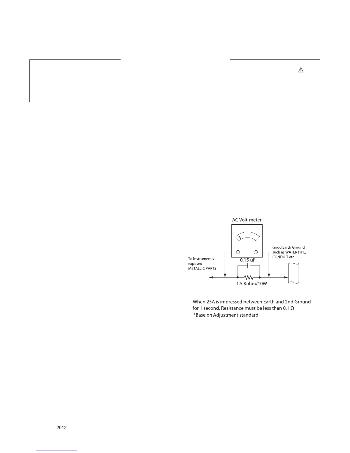
Leakage Current Hot Check (See below Figure)
Plug the AC cord directly into the AC outlet.
Do not use a line Isolation Transformer during this check.
Connect 1.5 K / 10 watt resistor in parallel with a 0.15 uF capacitor
between a known good earth ground (Water Pipe, Conduit, etc.)
and the exposed metallic parts.
Measure the AC voltage across the resistor using AC voltmeter
with 1000 ohms/volt or more sensitivity.
Reverse plug the AC cord into the AC outlet and repeat AC voltage
measurements for each exp ose d metallic par t. Any voltage
measured must not exceed 0.75 volt RMS which is corresponds to
0.5 mA.
In case any measurement is out of the limits specified, there is
possibility of shock hazard and the set must be checked and
repaired before it is returned to the customer.
Leakage Current Hot Check circuit
IMPORTANT SAFETY NOTICE
SAFETY PRECAUTIONS

- 4 -
LGE Internal Use OnlyCopyright © LG Electronics. Inc. All rights reserved.
Only for training and service purposes
SPECIFICATION
NOTE : Specifications and others are subject to change without notice for improvement
.
1. Application range
This spec sheet is applied to the 32/42/47/55/60/65LCD TV
used LT22E chassis.
2. Test condition
Each part is tested as below without special notice.
1) Temperature : 25 ºC ± 5 ºC (77 ºF ± 9 ºF), CST : 40 ºC±5 ºC
2) Relative Humidity: 65 % ± 10 %
3) Power Voltage : S ta ndard i nput voltage (100~240V@
50/60Hz)
4) Specification and performance of each parts are followed
ea ch drawing and s pe cificatio n b y p art number in
accordance with BOM.
5) The receiver must be operated for about 5 minutes prior to
the adjustment.
3. Test method
1) Performance: LGE TV test method followed
2) Demanded other specification
- Safety : CE, IEC specification
- EMC : CE, IEC
 Loading...