

LG 42LH50 Training Manual
42LH50 Direct View LCD
42LH50 Direct View LCD
1080P
Direct View LCD
Updated February 17th2010
Original: August 2009

OUTLINE
OUTLINE
Section 1
Section 2
Contact Information, Preliminary Matters, Specifications,
LCD Overview, General Troubleshooting Steps,
Signal Distribution, Disassembly Instructions and Voltages
Circuit Board Operation, Troubleshooting of :
• Switch mode Power Supply/Ballast Combination
• Main Board
Internet ConnectionNew
• Ft Control Board
• Side Keys
2
August 2009 42LH50

Overview of Topics to be Discussed
Overview of Topics to be Discussed
42LH50 LCD Direct View Display
This Section will cover Contact Information and remind the Technician of Important Safety Precautions for
the Customers Safety as well as the Technician and the Equipment.
Basic Troubleshooting Techniques which can save time and money sometimes can be overlooked. These
techniques will also be presented.
Section 1
This Section will get the Technician familiar with the Disassembly, Identification and Layout of the LCD
Display Panel.
At the end of this Section the Technician should be able to Identify the Circuit Boards and have the ability
and knowledge necessary to safely remove and replace any Circuit Board or Assembly.
3
August 2009 42LH50

Preliminary Matters (The Fine Print)
Preliminary Matters (The Fine Print)
IMPORTANT SAFETY NOTICE
IMPORTANT SAFETY NOTICE
The information in this training manual is intended for use by persons possessing an adequate background in
electrical equipment, electronic devices, and mechanical systems. In any attempt to repair a major Product,
personal injury and property damage can result. The manufacturer or seller maintains no liability for the
interpretation of this information, nor can it assume any liability in conjunction with its use. When servicing this
product, under no circumstances should the original design be modified or altered without permission from LG
Electronics. Unauthorized modifications will not only void the warranty, but may lead to property damage or
user injury. If wires, screws, clips, straps, nuts, or washers used to complete a ground path are removed for
service, they must be returned to their original positions and properly fastened.
CAUTION
CAUTION
To avoid personal injury, disconnect the power before servicing this product. If electrical power is required for
diagnosis or test purposes, disconnect the power immediately after performing the necessary checks. Also be
aware that many household products present a weight hazard. At least two people should be involved in the
installation or servicing of such devices. Failure to consider the weight of an product could result in physical
injury.
4
August 2009 42LH50

(Electrostatic Static Discharge)
ESD Notice
ESD Notice
Today’s sophisticated electronics are electrostatic discharge (ESD) sensitive. ESD can weaken or damage
the electronics in a manner that renders them inoperative or reduces the time until their next failure.
Connect an ESD wrist strap to a ground connection point or unpainted metal in the product. Alternatively,
you can touch your finger repeatedly to a ground connection point or unpainted metal in the product. Before
removing a replacement part from its package, touch the anti-static bag to a ground connection point or
unpainted metal in the product. Handle the electronic control
repackaging a failed electronic control assembly in an anti-static bag, observe these same precautions.
Regulatory Information
Regulatory Information
This equipment has been tested and found to comply with the limits for a Class B digital device, pursuant to
Part 15 of the FCC Rules. These limits are designed to provide reasonable protection against harmful
interference when the equipment is operated in a residential installation. This equipment generates, uses,
and can radiate radio frequency energy, and, if not installed and used in accordance with the instruction
manual, may cause harmful interference to radio communications. However, there is no guarantee that
interference will not occur in a particular installation. If this equipment does cause harmful interference to
radio or television reception, which can be determined by turning the equipment off and on, the user is
encouraged to try to correct the interference by one or more of the following measures: Reorient or relocate
the receiving antenna; Increase the separation between the equipment and the receiver; Connect the
equipment to an outlet on a different circuit than that to which the receiver is connected; or consult the
dealer or an experienced radio/TV technician for help.
(Electrostatic Static Discharge)
assembly by its edges only. When
5
August 2009 42LH50
Contact Information
Contact Information
Customer Service (and Part Sales) (800) 243-0000
Technical Support (and Part Sales) (800) 847-7597
USA Website (GCSC) aic.lgservice.com
Customer Service Website us.lgservice.com
LG Web Training lge.webex.com
LG CS Academy lgcsacademy.com
LCD-DV:
PLASMA:
Also available on the
Also available on the
Plasma page
Plasma page
32LG40, 32LH30, 37LH55, 42LG60, 42LG70, 42LH20, 42LH40, 42LH50,
42LH90, 42SL80, 47LG90, 47LH85
42PG20, 42PQ20, 42PQ30, 50PG20, 50PS80, 50PS60, 60PS11
Plasma Panel
Alignment Handbook
Published August 2010 by LG Technical Support and Training
LG Electronics Alabama, Inc. 201
Presentations
with Audio/Video
and Screen Marks
http://136.166.4.200
New Training Materials on
New Training Materials on
the Learning Academy site
the Learning Academy site
James Record Road, Huntsville,
AL, 35813.
6
August 2009 42LH50

LCD DIRECT VIEW OVERVIEW
LCD DIRECT VIEW OVERVIEW
Safety and Handling Regulations
1. Approximately 20 minute pre-run time is required before any adjustments are performed.
2. Voltage levels on SMPS are factory adjusted and sealed. VR301 and VR302.
3. Be cautious of electric shock from the Backlight section, it uses high voltage AC. Check
that the Power Supply and Drive Circuits are completely discharged because of residual
current stored before Circuit Board removal.
4. C-MOS circuits are sensitive to static electricity, use caution when dealing with Circuit
boards. Always handle the circuit boards on the outside edges, while wearing a static wrist
strap.
5. Exercise care when making voltage and waveform checks to prevent damaging the unit
and service equipment.
6. Be cautious of lost screws and other metal objects to prevent a possible short in the
circuitry.
Checking Points to be Considered
1. Check the appearance of the Replacement Panel and Circuit Boards for both physical
damage and part number accuracy.
2. Check the model label. Verify model names and board model matches.
3. Check details of defective condition and history. Example: Oscillator failure dead set, etc…
7
August 2009 42LH50

Basic Troubleshooting Steps
Basic Troubleshooting Steps
Define, Localize, Isolate and Correct
•Define
the failure. Use your senses Sight, Smell, Touch and Hearing. Look for burned parts and
check for possible overheated components. Capacitors will sometimes leak dielectric material
and give off a distinct odor. Frequency of power supplies will change with the load, or listen for
relay closing etc. Observation of the front Power LED may give some clues.
•Localize
checked and after giving a thorough examination using your senses the first check should
always be the DC Supply Voltages to those circuits under test. Always confirm the supplies
are not only the proper level but be sure they are noise free. If the supplies are missing check
the resistance for possible short circuits.
•Isolate
Oscilloscope to make a final determination of the failure. Look for correct Amplitude Phasing
and Timing of the signals also check for the proper Duty Cycle of the signals. Sometimes
“glitches” or “road bumps” will be an indication of an imminent failure.
Look at the symptom carefully and determine what circuits could be causing
After carefully checking the symptom and determining the circuits to be
To further isolate the failure, check for the proper waveforms with the
•Correct
check the DC Supplies for proper levels. Make all necessary adjustments and lastly always
perform a Safety AC Leakage Test before returning the product back to the Customer.
The final step is to correct the problem. Be careful of ESD and make sure to
8
August 2009 42LH50
42LH50 PRODUCT INFORMATION
42LH50 PRODUCT INFORMATION
This section of the manual will discuss the specifications of the 42LH50
LCD Direct View Display Panel.
9
August 2009 42LH50

Basic Specifications
Basic Specifications
Key Features
• LG NetCast™ Entertainment Access*
• (Netflix®, YouTube™, Yahoo!® Widgets,
• My Media Access CIFS)
• TruMotion 120Hz
• Full HD 1080p HD Resolution
• 70,000:1 Dynamic Contrast Ratio
• 2.7ms Response Time (GTG)
• 500 cd/m2 Brightness
• Wide Color Gamut
• Super IPS Panel
• Wide Viewing Angle
• XD Engine®
• 24p Real Cinema
• ISFccc® Ready
• Picture Wizard
• AV Mode II (Cinema, Sports, Game)
• 60,000 Hour Panel Life (typical)
• NTSC/ATSC Tuners with Clear QAM
10
August 2009 42LH50
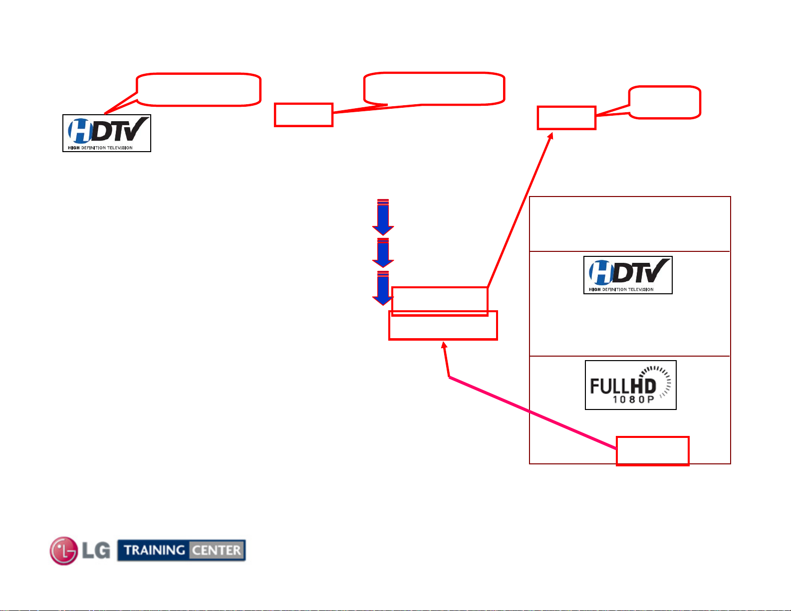
Pixel Count to Resolution Comparisons
Pixel Count to Resolution Comparisons
NTSC
SD
HD
HD
HD
720P Logo
HD RESOLUTION 720p HD Resolution Pixels: 1365 (H) × 768 (V)
High definition television is the highest performance segment of the
DTV system used in the US. It’s a wide screen, high-resolution video
image, coupled with multi-channel, compact-disc quality sound.
720P Panel
FORMATS
480I
480P
1080I
720P
1080P
Interlaced
Progressive
Interlaced
Progressive
Progressive
240 Lines
480 Lines
540 Lines
720 Lines
1080 Lines
768
BASIC
PIXEL COUNTS
720P Panel
1365 (H) × 768 (V)
Possible Frame
Rates:
24FPS
30FPS
60FPS
Interlaced
2 Fields to make a Frame
1080P Panel
Progressive
1920 (H) x 1080 (V)
Each Field is a Frame
Think of sync as the Panels “Refresh Rate”
11
August 2009 42LH50

Basic Specifications (LOGO Familiarization)
Basic Specifications (LOGO Familiarization)
Full HD 1080p Resolution
Displays HDTV programs in full 1920 x 1080p resolution for a more detailed picture.
12
August 2009 42LH50
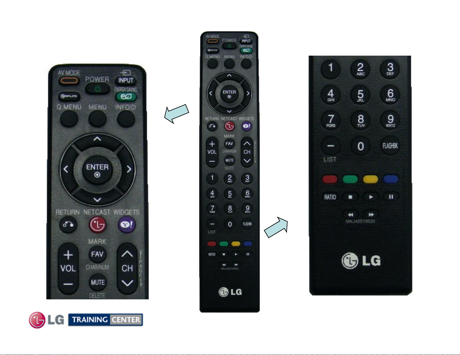
Remote Control
Remote Control
Familiarization
Familiarization
TOP PORTION
BOTTOM PORTION
13
August 2009 42LH50
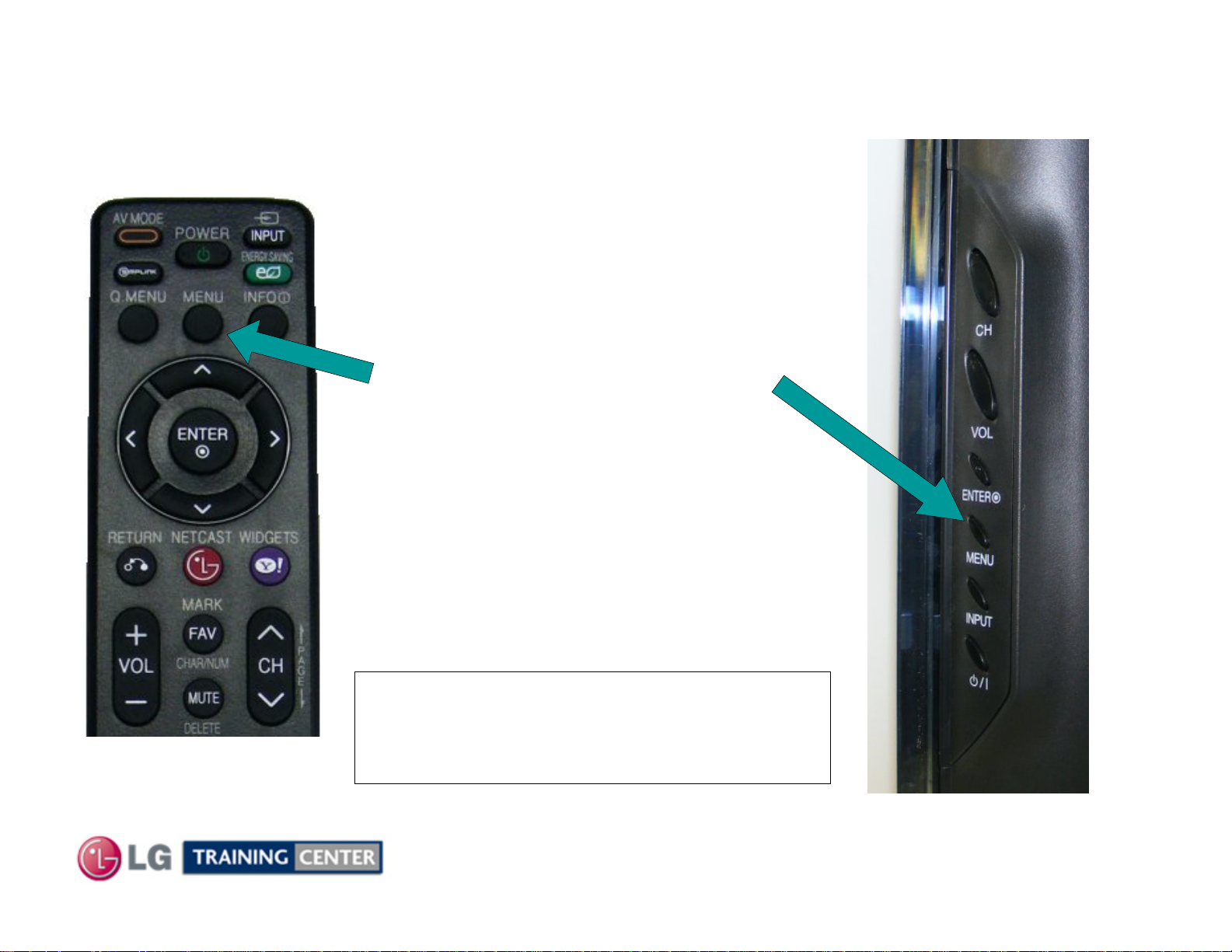
Accessing the Service Menu
Accessing the Service Menu
REMOTE
BOTTOM PORTION
To access the Service Menu.
1) Turn the Set On
2) Simultaneously, Press and
“Hold” the Menu Key on the
Side Key pad and Press and
“Hold” the Menu Key on the
Remote approximately 5
seconds.
3) If Customer’s Menu appears,
continue to hold until it
disappears.
SIDE KEYS
4) The Service Menu appears
Note: If a Password is required to
enter the Service Menu. Enter;
0000
14
August 2009 42LH50
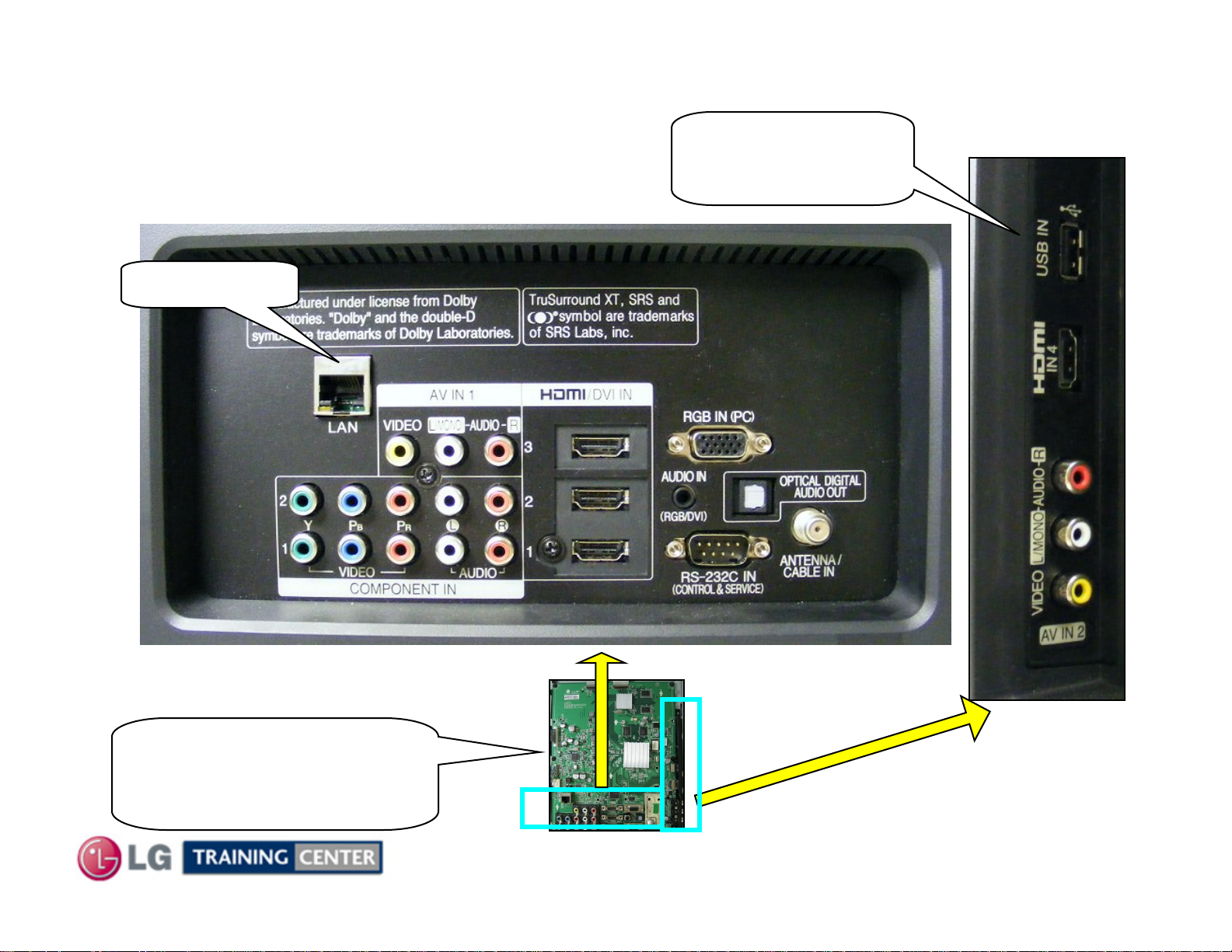
Rear and Side Input Jacks
Rear and Side Input Jacks
Internet Port
Rear In/Out Jacks
USB Port
Software Upgrades
Music, Photos
Side In/Out
MAIN PWB
Rear and Side
Input/Output locations
15
August 2009 42LH50
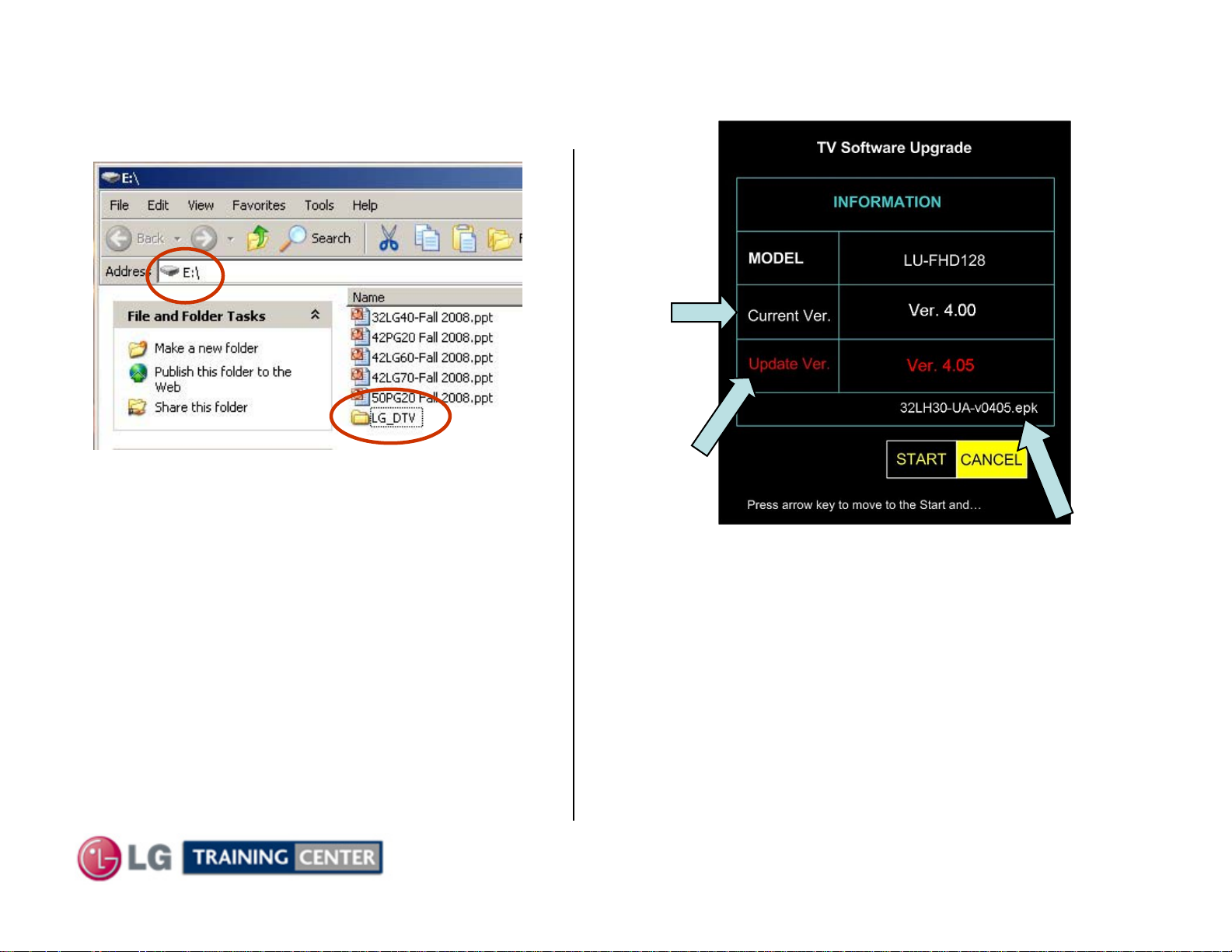
Software Upgrade Procedure
Software Upgrade Procedure
1) Create an LG_DTV folder on the USB Flash Drive
Shows the
Currently
Installed
Version
2) Copy new software (xxx.epk) to "LG_DTV"
folder. Make sure to have correct software file.
3) With TV turned on, insert USB flash drive.
4) You can see the message
“TV Software Upgrade” (See figure to right)
5) Cursor left and highlight "START" Button and
push “Enter” button using the remote control.
6) You can see the download progress Bar.
7) Do not unplug until unit has automatically
restarted.
8) When download is completed, you will see
“COMPLETE”.
9) Your TV will be restarted automatically.
Shows the
Software
Version
found on the
USB Flash
Drive
Shows the
Software file found
on the USB Flash
Drive
* CAUTION:
Do not remove AC power or the USB Flash Drive.
Do not turn off Power, during the upgrade
process.
16
August 2009 42LH50
nd
How to Perform a Manual Software Update (2
How to Perform a Manual Software Update (2
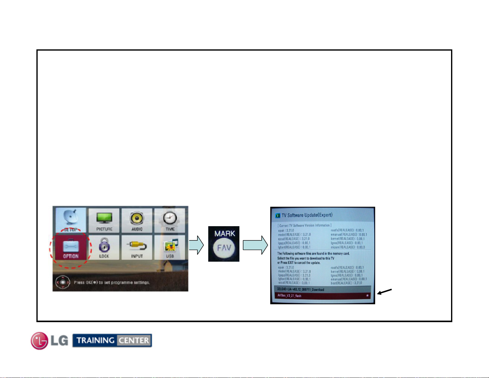
1. (Remove all cables).
2. Plug USB Memory (Jump drive) into the USB jack (front input).
The (epk) file must be in a Sub-Folder named “LG_DTV” on the jump drive.
3. Bring up the Customer’s Menu. Highlight the “OPTION” selection. (See Fig 1)
4. Press “FAV/MARK” button on the remote controller 7 times. (See Fig 2)
5. A Pop-Up window appears (See Fig 3). Using Cursor keys, select the correct file.
6. Press the “SELECT” key on the remote.
7. A Progress bar appears indicating that the download is in progress. Same as Automatic Mode.
(Do not remove AC during this time).
8. When the download is complete the TV will automatically restart.
9. Turn off TV and remove AC for 30 seconds.
Re-apply AC and turn the TV on.
nd
Choice)
Choice)
Fig 1
Press 7 times
Fig 2
17
Be very careful.
Make sure you
have selected the
correct
Upgrade File
before pressing
“SELECT”.
Fig 3
August 2009 42LH50
How to Upgrade EDID Data
How to Upgrade EDID Data
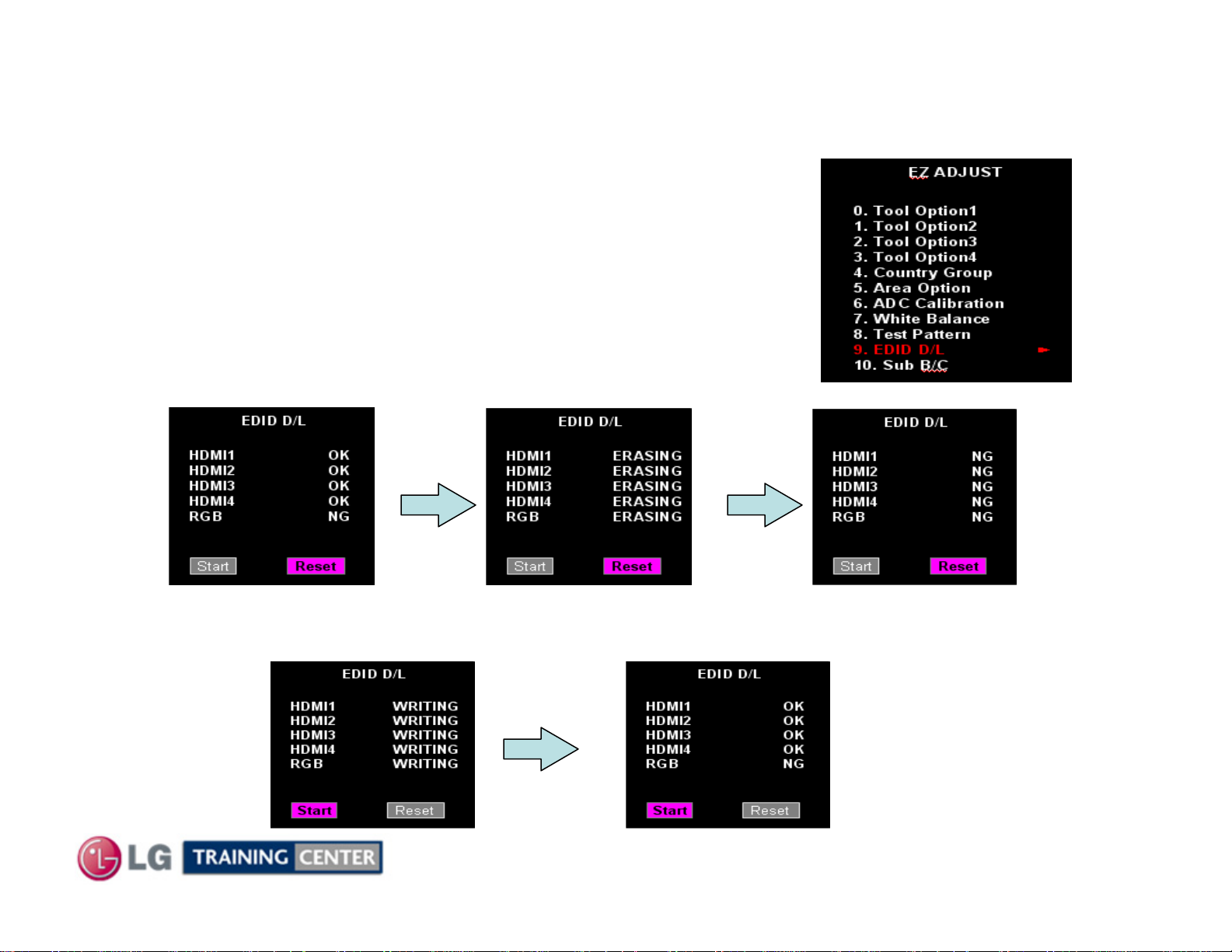
Caution : Before upgrading EDID data, the Software Upgrade should have
already been performed.
Remove all cables for the Television.
1. Press the ADJ key on the Service Remote to display EZ ADJUST Menu.
(See Figure A on the right)
2. Using the cursor down key, Highlight EDID D/L selection and press “SELECT”
on the remote. (See Figure A)
3. A “Pop-Up” screen showing the EDID status as OK appears. (See Figure B)
4. Using the Cursor keys, Highlight “RESET” and press “SELECT”.
(See Figures C and D)
The EDI Data is first Erased and the status is shown as NG.
Fig B Fig C Fig D
Fig A
5. Highlight “START” and press “Select” to download and update EDID. (See Figure E through F)
First the EDID Data is written into memory.
Fig E Fig F
Then the Status is shown as OK
18
August 2009 42LH50
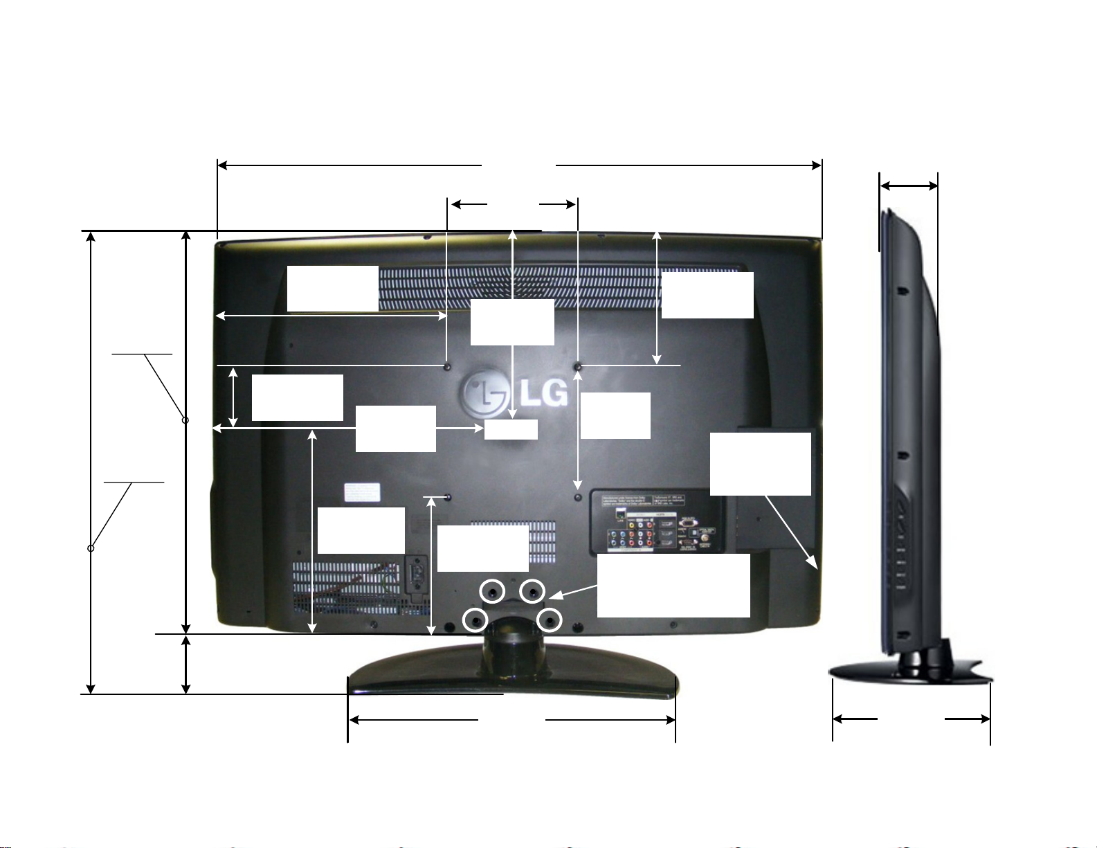
42LH50 Product Dimensions
42LH50 Product Dimensions
There must be at least 4 inches of Clearance on all sides
Wattage
Average 197W
Stand By 0.22W
42LH50 Dimensions
41-3/8"
1051.6mm
7-7/8"
200mm
3-5/8"
91.4mm
25-7/8"
657.9mm
28-5/16"
718.8mm
2-3/8"
60.96mm
16-3/4"
425mm
4-1/16"
103.8mm
20-11/16"
518mm
12-15/16"
327.8mm
12-15/16"
327.8mm
Center
8-7/8"
225mm
8-13/16"
224mm
7-7/8"
200mm
Model No.
Serial No.
Label
Remove 4 screws to
remove stand for
wall mount
Weight without Stand: 37.9 lb
Weight with Stand: 41.9 lb
19-15/16"
506mm
19
11-11/16"
297.1mm

DISASSEMBLY AND TROUBLESHOOTING SECTION
DISASSEMBLY AND TROUBLESHOOTING SECTION
Disassembly:
This section of the manual will discuss Disassembly, Layout and Circuit
Board Identification, of the 42LH50 LCD Direct View Television.
Upon completion of this section the Technician will have a better understanding of
the disassembly procedures, the layout of the printed circuit boards and be able to
identify each board.
Troubleshooting:
This section of the manual will also discuss troubleshooting.
Upon completion of this section the Technician will have a better understanding of
how to diagnosis and resolve problems.
20
August 2009 42LH50
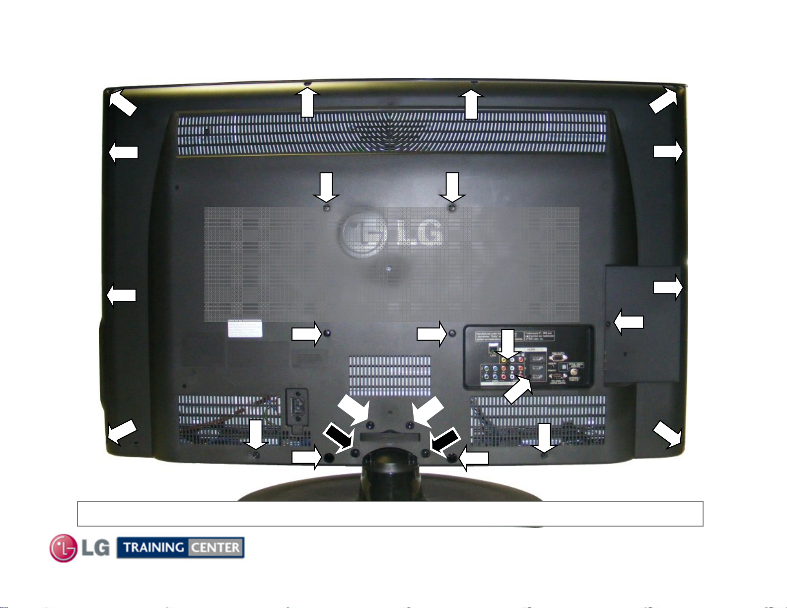
Removing the Back Cover
Removing the Back Cover
Remove the 23 screws indicated.
Pay attention to the size and type of screw
as there are many different types.
Putting in an improper screw when
reassembling may Cause damage.
The Stand and its bottom two screws do not need to be removed before removing the back.
21
August 2009 42LH50
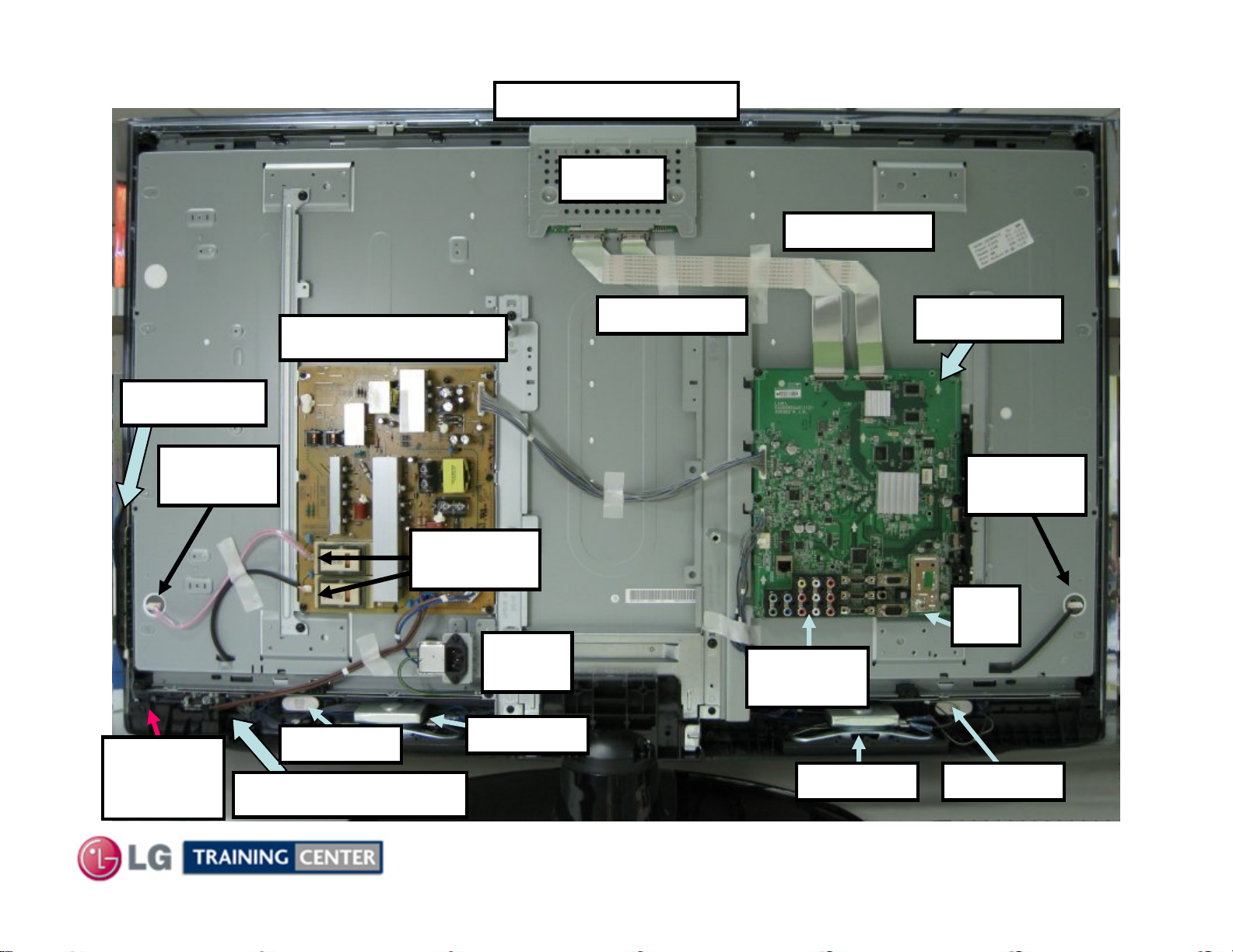
Circuit Board Layout
Circuit Board Layout
T-CON p/n EAT60663701
T-CON
LVDS Cable
Side Keys
Backlight
Connection
Master
Power
Switch
POWER SUPPLY
Backlight
Connections
Tweeter R
Ft IR/LED Control
AC
Input
Speaker R
LVDS Cable
Rear
Inputs
Speaker L
Main PWB
Backlight
Connection
RF
Input
Tweeter L
22
August 2009 42LH50
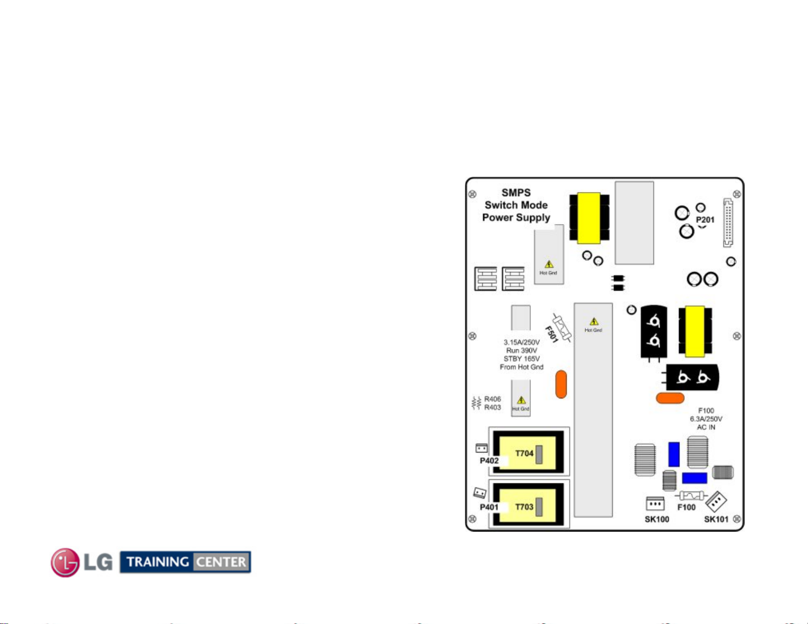
POWER SUPPLY SECTION
POWER SUPPLY SECTION
Note: If the Master Power Switch is off, this power supply is completely off.
This switch mode power supply has the ballast section built in.
The power supply develops Stand By 5V, 12V and 24V for the Main board.
This power supply draws a little less that 1 watt during stand
by mode. The fuse F501 reads 73VDC (from hot ground)
during this time. When the controller chip (on the back)
receives the PWR-ON command via P201 Pin 19, the primary
section increases its current supplying ability. The Primary
fuse F501 now reads 390V.
12V is routed out P201 pins 5 and 6 and
24V is routed out P201 pins 1 and 2.
Internally, the power supply also sends B+ (390V) voltage to
the Ballast section but it is not turned on at this time.
When the power supply receives the INV-ON command via
P201 pin 20, it is routed to the driver for the ballast (on the
back of the board). The driver now starts to deliver drive
information to the output FETs (on the far left hand heat sink)
which in turn switch the primary sides of the two ballast
transformers T703 and T704. They output 1.2Kv (48Khz)
pulses to the backlights via P401 and P402.
23
August 2009 42LH50
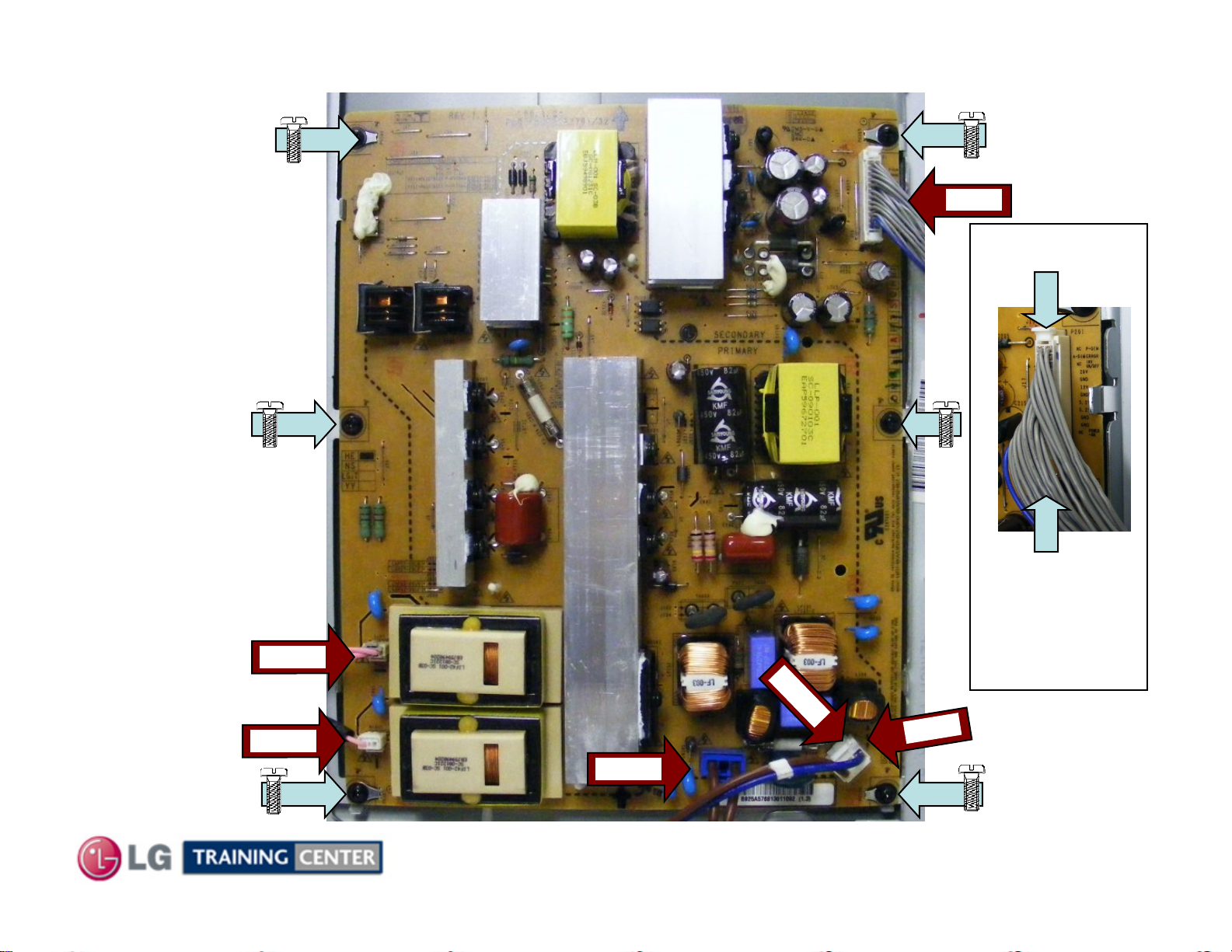
Power
Power
Supply PWB
Supply PWB
Removal
Removal
P201
Disconnect
P201, P401,
P402, AC In
SK101 and
SK102.
Remove the 6
screws indicated
by the arrows
w/screw.
P402
P401
SK
P201
Press in
Two tabs
to release
lock
1
0
1
In
C
A
SK102
24
August 2009 42LH50
 Loading...