

LG Electronics 37LH255H, 37LH250H, 32LH255H, 37LH265H, 37LH260H User Manual
...
32LH250H 37LH250H 42LH250H
32LH255H 37LH255H 42LH255H
37LH260H 42LH260H
37LH265H
Lodging Guest Interactive TVs
Commercial Mode Setup Guide
Note: Selected features shown within this guide may not be available on all models.
EXPERIENCED INSTALLER
Commercial Mode Setup
page 7
b-LAN™ Setup & Overview
page 42
Cloning Information
pages 20–23
© Copyright 2010, LG Electronics U.S.A., Inc.
Part No: 206-4118
WARNING
RISK OF ELECTRIC SHOCK
DO NOT OPEN
For Customer Support/Service, please call:
1-888-865-3026
The latest product information and documentation is
available online at:
www.LGcommercial.com/products
MODEL and SERIAL NUMBER
The model and serial numbers of this TV are located on the
back of the cabinet. For future reference, LG suggests that
you record those numbers here:
Model No._________________Serial No. _______________
WARNING:
TO REDUCE THE RISK OF ELECTRIC SHOCK DO NOT REMOVE COVER (OR BACK). NO USERSERVICEABLE PARTS INSIDE. REFER TO QUALIFIED SERVICE PERSONNEL.
The lightning flash with arrowhead symbol, within an equilateral triangle, is intended to alert the user to
the presence of uninsulated “dangerous voltage” within the product’s enclosure that may be of sufficient
magnitude to constitute a risk of electric shock to persons.
The exclamation point within an equilateral triangle is intended to alert the user to the presence of impor-
tant operating and maintenance (servicing) instructions in the literature accompanying the appliance.
WARNING:
TO PREVENT FIRE OR SHOCK HAZARDS, DO NOT EXPOSE THIS PRODUCT TO RAIN OR MOISTURE.
POWER CORD POLARIZATION:
This product is equipped with a 3-wire grounding-type alternating current power plug. This plug will fit into the power
outlet only one way. This is a safety feature. If you are unable to insert the plug fully into the outlet, contact your electrician to replace your obsolete outlet. Do not defeat the safety purpose of the 3-wire grounding-type plug.
NOTE TO CABLE/TV INSTALLER:
This reminder is provided to call the cable TV system installer’s attention to Article 820-40 of the National Electric
Code (U.S.A.). The code provides guidelines for proper grounding and, in particular, specifies that the cable ground
shall be connected to the grounding system of the building, as close to the point of the cable entry as practical.
REGULATORY INFORMATION:
This equipment has been tested and found to comply with the limits for a Class B digital device, pursuant to Part 15 of
the FCC Rules. These limits are designed to provide reasonable protection against harmful interference when the
equipment is operated in a residential installation. This equipment generates, uses and can radiate radio frequency
energy and, if not installed and used in accordance with the instruction manual, may cause harmful interference to radio
communications. However, there is no guarantee that interference will not occur in a particular installation. If this equipment does cause harmful interference to radio or television reception, which can be determined by turning the equipment off and on, the user is encouraged to try to correct the interference by one or more of the following measures:
• Reorient or relocate the receiving antenna.
• Increase the separation between the equipment and receiver.
• Connect the equipment to an outlet on a circuit different from that to which the receiver is connected.
• Consult the dealer or an experienced radio/TV technician for help.
CAUTION:
Do not attempt to modify this product in any way without written authorization from LG Electronics U.S.A., Inc.
Unauthorized modification could void the user’s authority to operate this product.
COMPLIANCE:
The responsible party for this product’s compliance is: LG Electronics U.S.A., Inc.
1000 Sylvan Avenue, Englewood Cliffs, NJ 07632, USA • Phone: 1-201-816-2000
Marketed and Distributed in the United States by LG Electronics U.S.A., Inc.
1000 Sylvan Avenue, Englewood Cliffs, NJ 07632
2
© Copyright 2010, LG Electronics U.S.A., Inc.
206-4118
IMPORTANT SAFETY INSTRUCTIONS
Important safeguards for you and your new product
THIS PRODUCT HAS BEEN MANUFACTURED AND TESTED WITH SAFETY IN MIND. IMPROPER
USE, HOWEVER, CAN RESULT IN POTENTIAL ELECTRICAL SHOCK OR FIRE HAZARDS. TO AVOID
DEFEATING THE SAFEGUARDS THAT HAVE BEEN BUILT INTO THIS PRODUCT, PLEASE READ AND
OBSERVE THE FOLLOWING SAFETY POINTS WHEN INSTALLING AND USING THIS PRODUCT.
1. Read these instructions.
Read all safety and operating instructions before oper-
ating the product.
2. Keep these instructions.
Retain the safety and operating instructions for future
reference.
3. Heed all warnings.
Adhere to all warnings on the product and in the oper-
ating instructions.
4. Follow all instructions.
Follow all operating and use instructions.
5. Do not use this apparatus near water.
Do not use this product near water or moisture or in an
area, such as a basement, that might become flooded.
6. Clean only with dry cloth.
Unplug this product before cleaning. When cleaning,
scrub gently with a soft cloth to prevent scratching. Do
not spray water or other liquids directly on the product
as electric shock may occur. Do not clean with chemicals such as alcohol, thinners, or benzene.
7. Do not block any ventilation openings. Install in
accordance with the manufacturer's instructions.
Install where there is proper ventilation. Do not install
in a confined space such as a bookcase. Do not cover
the product with cloth or other materials (e.g., plastic)
while it is plugged in. Do not install in excessively dusty
places. Do not touch ventilation openings, as they may
become hot while the product is operating.
8. Do not install near any heat sources, such as radiators, heat registers, stoves, or other apparatus
(including amplifiers) that produce heat.
9. Do not defeat the safety purpose of the polarized
or grounding-type plug. A polarized plug has two
blades with one wider than the other. A groundingtype plug has two blades and a third grounding
prong. The wide blade or the third prong are provided for your safety. If the provided plug does not
fit into your outlet, consult an electrician for
replacement of the obsolete outlet.
10. Protect the power cord from being walked on or
pinched, particularly at plugs, convenience receptacles, and the point where it exits from the apparatus.
11. Only use attachments/accessories specified by the
manufacturer.
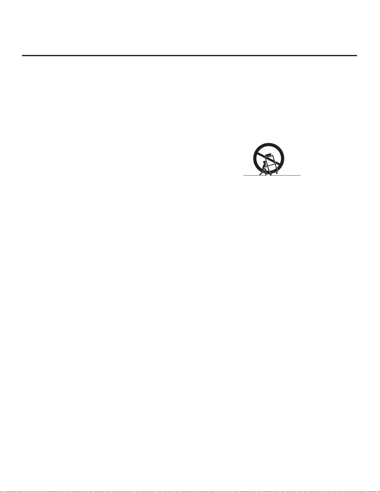
12. Use only with the cart, stand, tripod, bracket, or
table specified by the manufacturer or sold with
the apparatus. When a cart is used, use caution
when moving the cart/apparatus combination in
order to avoid injury from tip-over.
PORTABLE CART WARNING
13. Unplug this product during lightning storms or
when unused for long periods of time.
Also, disconnect the antenna or cable system to prevent damage to the product due to lightning and power-line surges. Never touch this apparatus or antenna
during a thunder or lightning storm.
14. Refer all servicing to qualified service personnel.
Servicing is required when the apparatus has been
damaged in any way, such as power-supply cord
or plug is damaged, liquid has been spilled or
objects have fallen into the apparatus, the apparatus has been exposed to rain or moisture, does not
operate normally, or has been dropped.
15. Wall or Ceiling Mounting
This product should be mounted to a wall or ceiling only
as recommended by the manufacturer. When mounting
a TV, make sure not to install the TV by the hanging
power and signal cables on the back of the TV.
16. Transporting Product
Make sure the product is turned off and unplugged and
that all cables have been removed. It may take two or
more people to carry larger TVs. Do not press against
or put stress on the front panel of the TV.
17. Disconnect Device
The main plug is used as the disconnect device. The
disconnect device must remain readily operable. Be
sure to grasp the plug when unplugging the power
cord. Do not pull on the power cord to unplug the TV.
18. Object and Liquid Impact/Entry
Do not allow an impact shock or any objects to fall into
the product, and do not drop items onto the screen. Do
not press strongly on the panel with a hand or sharp
object, and never push objects of any kind into the panel
or through openings as they may damage the product
and/or touch dangerous voltage points or short-out parts
that could result in a fire or electric shock. Never
uid of any kind on the product.
(Continued on next page)
spill liq-
206-4118
3
IMPORTANT SAFETY INSTRUCTIONS
(Continued from previous page)
19. Power Sources
This product should be operated only from the type of
power source indicated on the marking label. If you are
not sure of the type of power supply to your installation,
consult your product dealer or local power company.
20. Overloading
Do not overload wall outlets and extension cords as this
can result in a risk of fire or electric shock. It is recommended that appliances be placed upon a dedicated
circuit; that is, a single outlet circuit which powers only
that appliance and has no additional outlets or branch
circuits. Overloaded wall outlets, loose or damaged wall
outlets, extension cords, frayed power cords, or damaged or cracked wire insulation are dangerous. Any of
these conditions could result in fire or electric shock.
21. Power Cord
Periodically examine the cord of your appliance, and if
its appearance indicates damage or deterioration,
unplug it, discontinue use of the appliance, and have
the cord replaced with an exact replacement part by
an authorized servicer. Protect the power cord from
physical or mechanical abuse, such as twisting, kinking, or pinching.
22. Outdoor Use/Wet Location
Warning: To prevent fire or electrical shock
hazards, do not expose this product to
rain, moisture, or other liquids.
Do not touch the product with wet hands. Do not install
this product near flammable objects such as gasoline or
candles or expose it to direct air conditioning. Do not
expose the product to dripping or splashing, and do not
place objects filled with liquids, such as vases, on or
over the apparatus (e.g., on shelves above the unit).
23. Grounding
Ensure that you connect the earth ground wire to prevent
possible electric shock (i.e., a TV with a three-prong
grounded AC plug must be connected to a three-prong
grounded AC outlet). If grounding methods are not possible, have a qualified electrician install a separate circuit
breaker. Do not try to ground the unit by connecting it to
telephone wires, lightning rods, or gas pipes.
24. Outdoor Antenna Grounding
If an outside antenna or cable system is connected to
the product, follow the precautions below.
An outdoor antenna system should not be located in
the vicinity of overhead power lines or other electric
light or power circuits or where it can come into contact with such power lines or circuits as death or serious injury can occur.
Be sure the antenna or cable system is grounded so
as to provide some protection against voltage surges
and built-up static charges.
4
Article 810 of the National Electrical Code (NEC) (in
the U.S.A.) provides information with regard to proper
grounding of the mast and supporting structure,
grounding of the lead-in wire to an antenna-discharge
unit, size of grounding conductors, location of
antenna-discharge unit, connection to grounding elec-
trodes, and requirements for the grounding electrode.
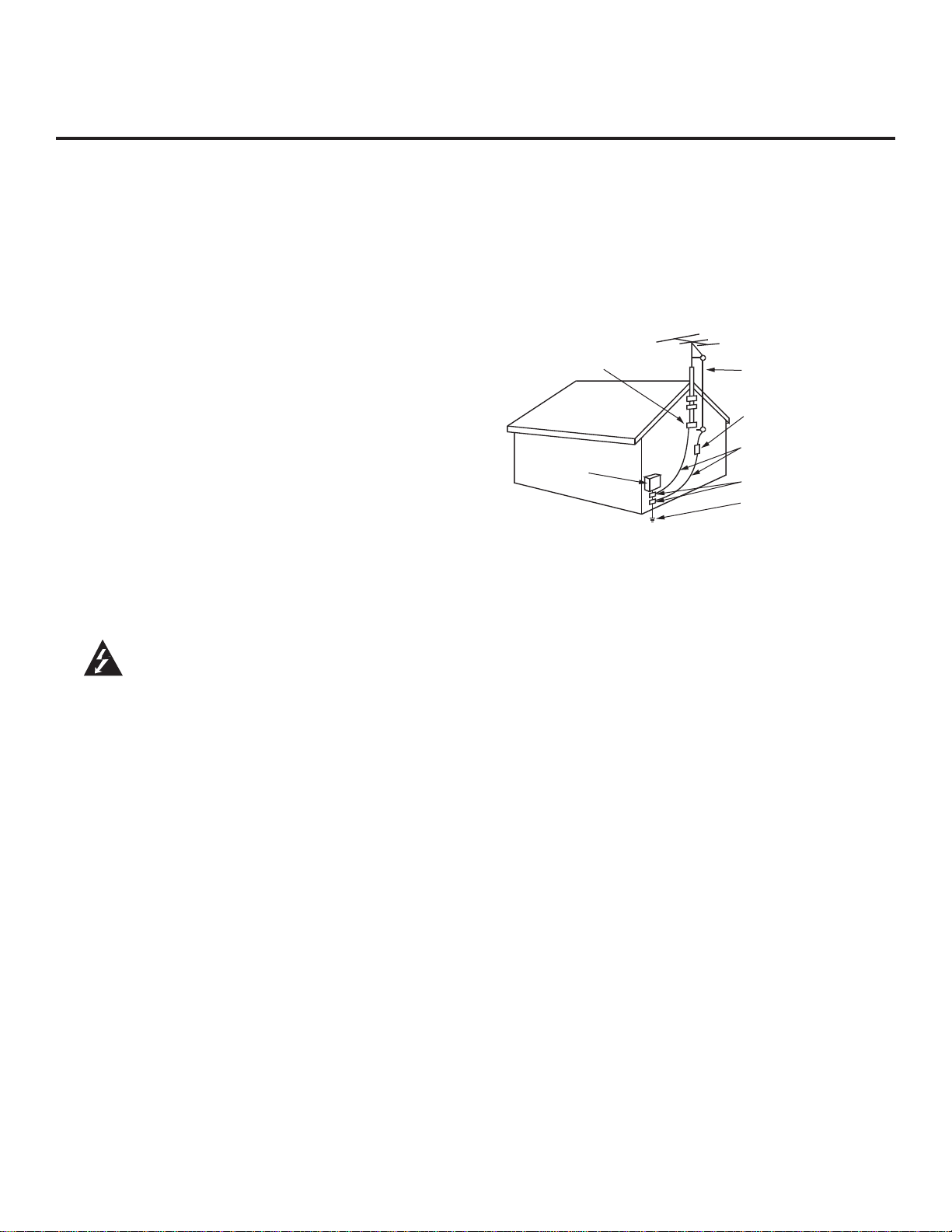
Antenna Grounding According to NEC, ANSI/NFPA 70
Ground Clamp
Electric Service
Equipment
Antenna Lead in Wire
Antenna Discharge Unit
(NEC Section 810-20)
Grounding Conductor
(NEC Section 810-21)
Ground Clamps
Power Service Grounding
Electrode System (NEC
Art 250, Part H)
25. Damage Requiring Service
Unplug this product from the wall outlet and refer ser-
vicing to qualified service personnel under the following conditions:
a. If the power-supply cord or plug is damaged.
b. If liquid has been spilled, or objects have fallen into
the product.
c. If the product has been exposed to rain or water.
d. If the product does not operate normally per the
operating instructions. Adjust only those controls
that are covered by the operating instructions, as an
improper adjustment of other controls may result in
damage and will often require extensive work by a
qualified technician to restore the product to its
normal operation.
e. If the product has been dropped, or the cabinet has
been damaged.
f. If the product exhibits a distinct change in perfor-
mance.
g. If you smell smoke or other odors coming from the
product or hear strange sounds.
26. Replacement Parts
When replacement parts are required, be sure the ser-
vice technician uses replacement parts specified by
the manufacturer or that have the same characteristics
as the original part. Unauthorized substitutions may
result in fire, electric shock, or other hazards.
27. Safety Check
Upon completion of any service or repairs to this product,
ask the service technician to perform safety checks to
determine that the product is in proper operating condition.
28. Sunlight
Keep the product away from direct sunlight.
206-4118

Table of Contents
Safety Warnings . . . . . . . . . . . . . . . . . . . . . . . . . . . . . . . 2
Important Safety Instructions . . . . . . . . . . . . . . . . . . . . 3–4
Table of Contents . . . . . . . . . . . . . . . . . . . . . . . . . . . . . . 5
Setup Checklist . . . . . . . . . . . . . . . . . . . . . . . . . . . . . . . 6
Commercial Mode Setup for Master TV . . . . . . . . . . . 7
Installer Overview . . . . . . . . . . . . . . . . . . . . . . . . . . . . . 8
Embedded b-LAN™ Module (EBL) FTG Mode of
Operation Overview . . . . . . . . . . . . . . . . . . . . . . . . . . 9–10
FTG Channel Map Overview . . . . . . . . . . . . . . . . . . . . . 11
FTG Installer Menu Overview . . . . . . . . . . . . . . . . . . . 12
FTG Operation Troubleshooting. . . . . . . . . . . . . . . . . . 13
Typical Installer Remote Control . . . . . . . . . . . . . . . . . 14
Installer Remote Control Key Functions. . . . . . . . . . . . 15
Rear Connections Panel . . . . . . . . . . . . . . . . . . . . . . . 16
Side Connections Panel / RF Antenna Connection . . . 17
RJP / TV Connections & Setup . . . . . . . . . . . . . . . . . . 18
TV Features Configuration Menus Overview . . . . . . . . 19
TLL-1100A Cloning Connections / Learning Setup . . . 20
LT2002 Cloning Connections / Learning Setup . . . . 21–22
LT2002 Cloning Connections / Teaching Setup . . . . . . 23
Installer Menu. . . . . . . . . . . . . . . . . . . . . . . . . . . . . 24–29
References
Detailed Instructions for Making a Master TV . . . . . . . 30
Adding Channel Icons / Custom Channel Labels (2-5-4 +
MENU Mode) . . . . . . . . . . . . . . . . . . . . . . . . . . . . . . . . 31
Clonable Menu Features / Checking Software Version 32
USB End User Features. . . . . . . . . . . . . . . . . . . . . . . . 33
USB Cloning / Master TV Profile Setup-Learning . . . . 34
USB Cloning / Master TV Profile Setup-Teaching . . . . 35
TV Camport Auto Sense Operation . . . . . . . . . . . . . . . 36
TV Aux Input Configuration . . . . . . . . . . . . . . . . . . . . . 37
General Troubleshooting . . . . . . . . . . . . . . . . . . . . . . . 38
LT2002 Cloning Procedure Troubleshooting . . . . . . . . 39
Troubleshooting Flow Chart . . . . . . . . . . . . . . . . . . . . . 40
Commercial Mode Check . . . . . . . . . . . . . . . . . . . . . . . 41
b-LAN Setup & Overview . . . . . . . . . . . . . . . . . . . . . . . 42
RJP Model List and Input Auto-sensing Hierarchy. . . . 43
Glossary of Terms . . . . . . . . . . . . . . . . . . . . . . . . . . . . 44
Document Revision History / Notes . . . . . . . . . . . . . . . 45
Back Cover. . . . . . . . . . . . . . . . . . . . . . . . . . . . . . . . . . 46
Notes
• This document does not include Commercial Mode Setup information for LH240H TVs. Refer to the Commercial
Mode Setup Guide for LH240H TVs for further information.
• Go to page 7 to begin the Commercial Mode Master TV setup.
• Refer to the “Installer Menu” section of this document to set up the operational features of the TV. Installer Menu content is intended for use primarily by qualified TV electronics technicians.
• This document references Installer Remote Controls used for menu operation. The remote information is provided for
reference only. The typical Installer Remote Control shown for reference in this document may be different from the
actual remote control supplied with the TV.
• For additional information, contact your LG representative.
Note: Design and specifications are subject to change without prior notice.
206-4118
5

Setup Checklist
Installation and Setup Checklist
__ Unpack TV and all accessories.
__ Install batteries in remote control.
__ Install TV on VESA mount or stand.
Note: It may be advisable to make all
hardwire connections before installing on
VESA mount or stand, as appropriate.
Hardware Connections
__ Install any additional hardware as
appropriate to your institution, LAN, etc.
Hardwire Connections
__ Make all connections to rear Jack Pack
and RF antenna on MPI card.
__ Make all connections to signal, interac-
tive resources, and Aux sources, as
appropriate.
TV-LINK
CFG
RJP
GAME
CONTROL
Y
VIDEO
PB
R
P
VIDEO
COMPONENT IN
AV IN 1
L(MONO)
AUDIO
L
AUDIO
RESET
UPDATE
REMOTE
RGB IN (PC)
.....
.....
.....
AUDIO IN
(RGB / DVI)
.....
....
RS-232C IN
(SERVICE ONLY)
HDMI
..........
2
R
R
1
HDMI/DVI IN
SPEAKER OUT
(8 )
..........
CONTROL OUT
Installer Menu Items Setup
__ Configure all relevant Installer Menu
items as required of your institution.
TV Menus Configuration
Configure TV features for the end user.
__ Channel
__ Picture
__ Audio
__ Option
__ Time
__ Lock
__ Choose on-screen menu language.
(English is the default language.)
Commercial Mode Setup
__ Complete Commercial Mode Setup
(see next page).
Software Installation
__ Install or configure any software, as
applicable, for example, Pay-Per-View
(PPV), etc.
Additional Features Setup
__ Select viewing source on TV.
(See also Table of Contents.)
6
206-4118
Commercial Mode Setup for Master TV
This page provides an overview of a Master TV configuration.
Note: Disconnect all Aux inputs. Under certain conditions, Auto Tuning
(Channel Search) is disabled if there is an Aux input active.
Commercial Mode Setup Procedure
1. Set Installer Menu Items
(Enter the TV Installer Menu—refer to the “Installer Menu” section of
this document for detailed instructions.)
a. Set Installer Menu item 117 FACT DEFAULT to 001, and press ENTER
on the Installer Remote. (This clears all Installer Menu custom settings,
channel labels / icons, etc. and reloads the factory default settings.)
b. Set item 003 BAND/AFC, as appropriate.
- Broadcast: Set to 000. - HRC: Set to 002.
- CATV: Set to 001. - IRC: Set to 003.
c. Set other particular installer items that affect your TV programming net-
work. Enable/disable Aux sources, set a Start Channel, etc.
d. After you have adjusted all required Installer Menu item settings, press
ENTER on the remote to exit the menu and save your changes.
2. Set Up TV Features
(Channel, Picture, Audio, Lock, Time, Option, Digital Captions, etc.
See TV Clonable Options list and TV Menus information.)
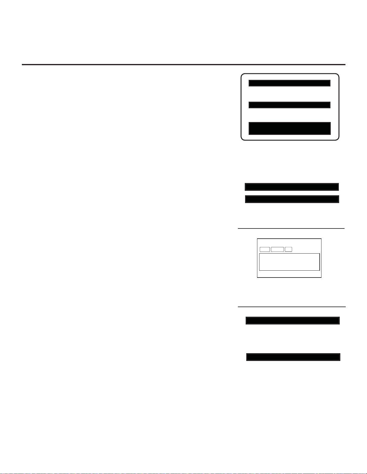
XXLH250H INSTALLER MENU
000 INSTALLER SEQ 000
UPN 000-000-000-000 FPGA E0F1
PTC V1.00.000 CPU V3.06.00
Typical TV Installer Menu
Note: The Installer Menu header will vary
depending on the TV you are setting up.
117 FACT DEFAULT 001
003 BAND/AFC 00X
Adjust the settings for these
Installer Menu items.
3. Run Auto Tuning (Channel Search)
a. (Search for all available channels.) Go to the Channel Menu, access
the Auto Tuning option, and follow the on-screen instructions.
b. Edit the Channel Scan. In the Channel Menu, access the Channel Edit
option.
• Add/delete channels per your system requirements.
Note: Physical channel numbers are used to identify virtual channels.
• Add familiar channel trademarks/logos like ABC, CBS, NBC, etc. to
the Channel-Time on-screen display. In the Channel Menu, select the
Channel Label option. Add identifiable labels (logos) for the end user
Custom Text Label “WXYZ” created in
2-5-4 + MENU (Add Channel Label) Mode.
to readily know what common networks are available.
4. Transfer TV Setup to Internal TV Controller: 2-5-5 + MENU Mode
After the TV channel scan has been edited and channel label icons
added, enter the Installer Menu. Once in the Installer Menu, press
093 RJP AVAILABLE 001
Set 093 RJP Available to 001 if using a
2-5-5 + MENU on the remote. This transfers the TV setup to the internal
controller box.
5. Add Custom Channel Labels for Analog Channels: 2-5-4 + MENU Mode
128 CH. OVERIDE 000
Enter the Installer Menu, and press 2-5-4 + MENU. Add your own custom
text labels to channel on-screen displays. Note: Digital Channels often
have a broadcaster generated label (see 2-5-4 + MENU reference informa-
After Master TV Setup is completed,
set item 028 CH. OVERIDE to 000.
tion). When you are finished, press MENU to exit 2-5-4 + MENU Mode.
Verify TV Setup
At this point, verify that the channel lineup, channel icons, and custom labels are correct.
Make sure the TV features are set per your requirements. Set item 028 CH. OVERIDE
to 000 to lock the channel scan and restrict Setup Menu access. After the preceding has
been completed, the Master TV Setup is ready to be copied to a Clone Programmer
(see cloning information in this document).
DIGITAL 19-3
STEREO SAP
MONO
WXYZ
Remote Jack Pack.
206-4118
7
Installer Overview
This is the Commercial Mode Setup guide only.
Operating Installer Menu
To set up the controls for the TV, you will need to know how to
enter the TV Installer Menu and make changes to the default
values as required. If necessary, familiarize yourself with the
TV Installer Menu and how to make and save changes in the
menu.
XXLH250H INSTALLER MENU
000 INSTALLER SEQ 000
UPN 000-000-000-000 FPGA E0F1
PTC V1.00.000 CPU V3.06.00
LG Installer Remote Control
You will need an LG Installer Remote similar to the one shown to
the right. The Installer Remote must have a SOURCE button or
its equivalent. The remote shown in this manual has an INPUT
button, which serves the purpose of a SOURCE button.
The TV’s clonable features need to be set up. This is a critical
step. If the Master TV display panel’s clonable features, such
as adding channel icons or channel labels, are not done correctly, the cloned TVs will all have problems. Refer to the
Owner’s Manual for information on other TV features: Video,
Audio, Closed Captions, V-Chip, etc.
TLL-1100A Clone Programmer
The TLL is a very simple cloner to use. It can be
TV Link
Loader-Demo
TLL1100A
Ready
MODE
MENU
set up to clone a Master TV Setup and transfer it
into a Target TV. Cloning is accomplished using
the TV/cloner MPI ports for communication.
Ensure the Master TV is set up completely.
Cloning is only possible when the TV is tuned to
an Aux source or an analog channel (not a digi-
ENTER
RECEIVE SEND
TLL1100A
tal channel).
Typical Installer Menu
MARK
POWER
RATIO
INPUT
CC
123
456
7809
FLASHBK
LIST
MUTE
VOL
MENU
TIMER
ALARM
CH
ENTER
RETURN
SAP
EJECT
P
A
G
E
8
206-4118
Embedded b-LAN™ Module (EBL) FTG Mode of Operation Overview
The following steps outline the FTG (Free-To-Guest) setup for individual TV control.
1. Set up commercial features of the TV. Enter the Installer Menu, and set all desired items as required (for
example, Tuning Band, Start Channel, etc.). Refer to the “Installer Menu” section of this document for fur-
ther information.
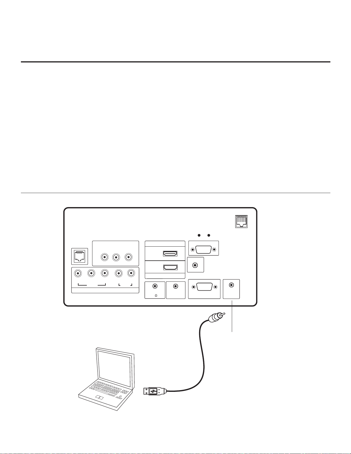
2. Install the FTG Configuration Application program on the PC that will be used to configure the EBL.
3. Connect the PC to the TV-LINK CFG jack on the rear panel using a USB-to-TTL serial cable
(TTL-232R-5V-AJ).
4. Launch the FTG Configuration Application, and create a new or open an existing FTG Configuration file.
5. Build a Channel Map and “write” it to the EBL (converts EBL from Pass-Through Mode to FTG Mode).
6. If necessary, make changes to Installer Menu items using the FTG Installer Menu Configuration Utility and
“write” the changes to the EBL in FTG Mode.
7. Save the FTG Configuration (.rml) file for future use.
8. Tune the TV to a Logical Channel in the Channel Map.
GAME
CONTROL
Y
AV IN 1
VIDEO
PB
R
P
VIDEO
COMPONENT IN
Laptop
AUDIO
L(MONO)
PC
L
AUDIO
TV-LINK
CFG
RJP
RESET
HDMI
..........
2
R
R
SPEAKER OUT
..........
1
HDMI/DVI IN
CONTROL OUT
(8 )
REMOTE
AUDIO IN
(RGB / DVI)
(SERVICE ONLY)
RGB IN (PC)
.....
.....
.....
.....
....
RS-232C IN
UPDATE
TV-LINK CFG
Use for local FTG
configuration.
USB-to-TTL Serial
Cable for Connection
to PC
206-4118
9

Embedded b-LAN™ Module (EBL) FTG Mode of Operation Overview
(Cont.)
To determine the operating mode of the TV, press MENU. If the Setup or TV Menu appears, the EBL is in Pass-Through
Mode. If the End User “Aspect Ratio” or “Function” menu appears, the TV is in FTG Mode.
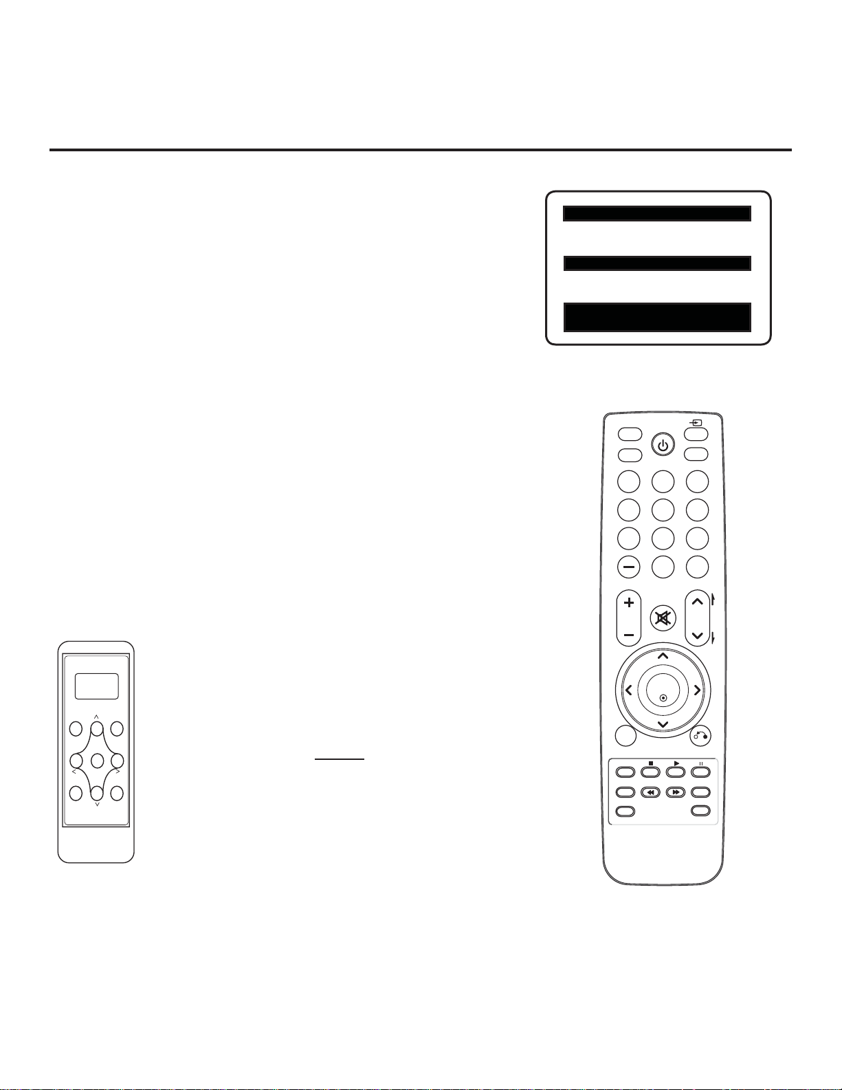
Communications Setup Menu
Sets up the communications link between the FTG
Configuration Application and the EBL in a TV.
CHANNEL
OPTION
PICTURE
LOCK
AUDIO
INPUT
TIME
USB
Typical TV Setup Menu
Shows that the EBL is in Pass-Through Mode . You can also
access this menu by turning IR Remote Access ON in the
FTG Configuration Application, while the TV is in FTG Mode.
ASPECT RATIO
Set By Program
ABC
4:3
16:9
Zoom
Just Scan
Move Enter
Network Icon Selection Menu
Select channel icons, such as ABC, NBC etc., to add to the channel OSDs to identify common networks for the end user.
10
End User “Aspect Ratio” or “Function” Menu
Shows that the EBL is in FTG Mode . While this menu is present on-screen, the only way the Installer Menu can be
accessed is via the FTG Configuration Application.
206-4118
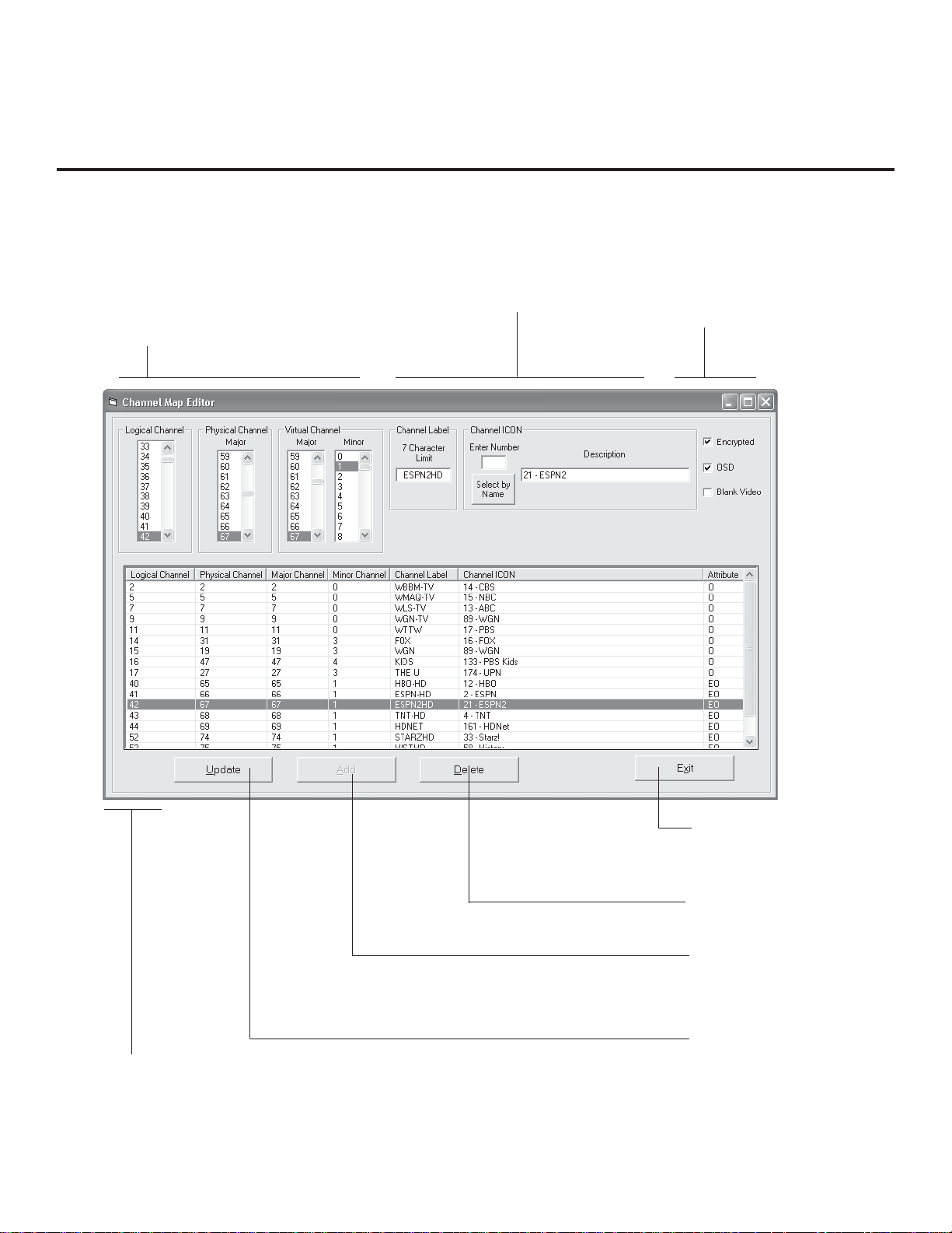
FTG Channel Map Overview
Writing a Channel Map into EBL will switch the EBL from Pass-Through Mode to FTG Mode. When the Aspect Ratio/
Function menu is present, EBL is in FTG Mode.
LOGICAL CHANNEL NUMBERS
Channels appear in numerical order.
Select Logical, Major, and Minor numbers
on menu.
CUSTOM CHANNEL LABELS/ICONS
Set custom labels and select icons on menu.
SET CHANNEL ATTRIBUTES
Set Encrypted and OSD on or off
or Blank Video only.
CHANNEL MAP EDITOR
Shows both Channel Data and Logical
Channel Lineup.
206-4118
EXIT
Exits menu and returns to
Logical Channel listing.
DELETE
Removes channel from lineup
ADD
After inputting a new
channel’s data, press to
add channel to list.
UPDATE
After editing a channel’s data,
press to include the changes
in the Channel List.
.
11
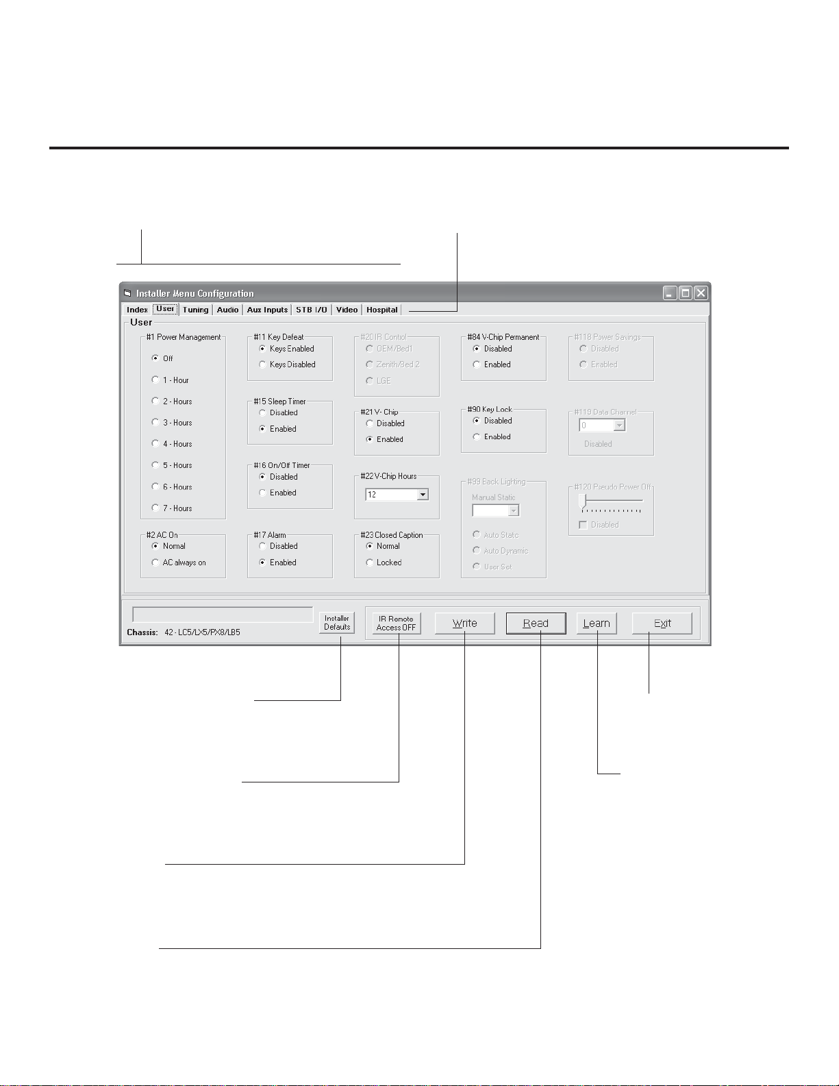
FTG Installer Menu Overview
CONFIGURATION SETTINGS
Select tabs for categories of Installer
Menu items to set up TV.
HOSPITAL-GRADE TV ONLY
Set Hospital items on Installer Menu for
hospital-grade TVs.
12
INSTALLER DEFAULTS
Press to reset FTG Installer
Menu items to defaults.
IR REMOTE ACCESS
Toggle IR Remote Access to ON to get access to
TV feature menus or Installer Menu.
WRITE
Press to transfer the FTG Installer
Menu values to the EBL.
READ
Press to transfer the Installer Menu values in the EBL to
the PC FTG Configuration Application.
EXIT
Returns to Logical Channel
Map Menu
LEARN
Press to transfer the Installer
Menu settings on the TV to
the EBL and PC FTG
Configuration Application
.
.
206-4118

FTG Operation Troubleshooting
The following table provides troubleshooting information for when EBL is configured in the FTG Mode
of operation.
FTG Operation Error Messages
Symptom Probable Cause(s) Solution(s)
Communication Error
(“Communications
Timeout”)
Cable(s) not connected. Check and connect communication
cables.
V not powered. Check/connect the TV power cord.
T
TV not turned ON. TV needs to be turned ON (default FTG
Mode).
Wrong COM
(communication) port.
In the FTG Configuration Application,
select the correct COM port for the cable
being used.
206-4118
13
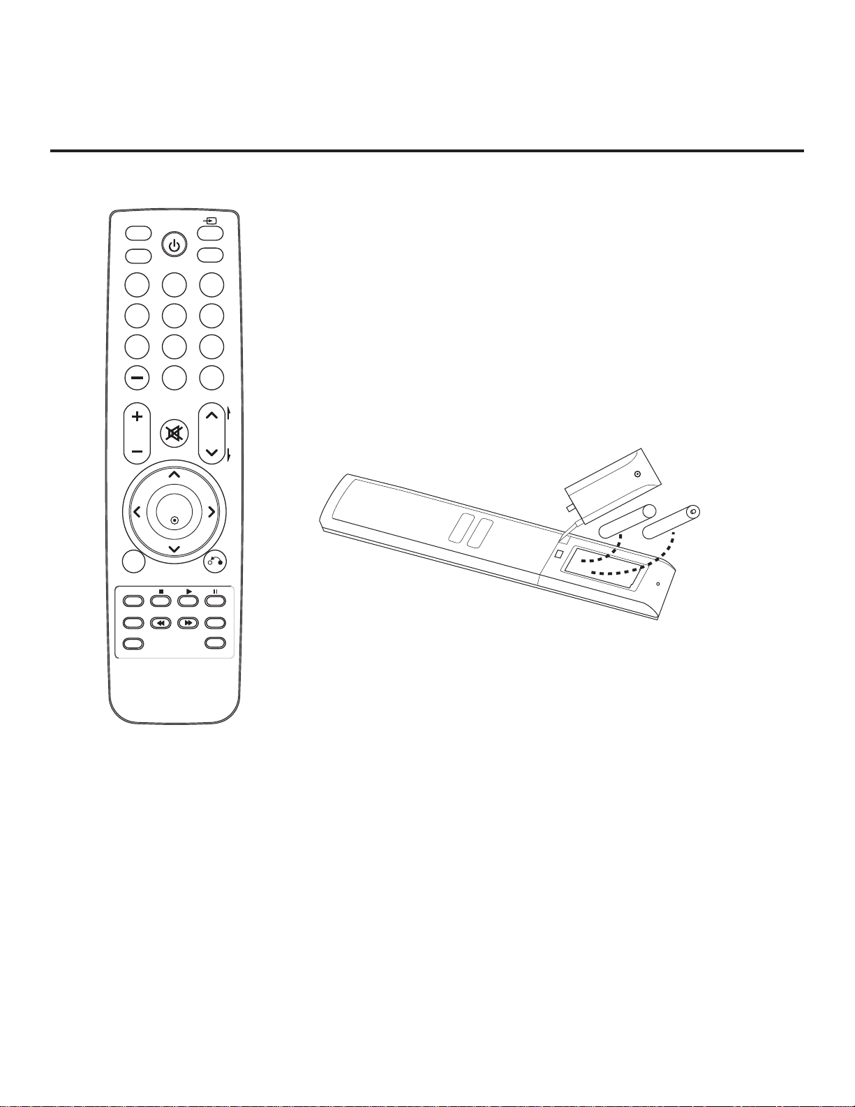
Typical Installer Remote Control
The LG Installer Remote is supplied with and dedicated to oper-
MARK
POWER
RATIO
INPUT
CC
123
456
7809
FLASHBK
LIST
MUTE
VOL
CH
P
A
G
E
ate the TV. Some DVD and VCR controls may be available for
selected LG DVD/VCR products.
See next page for typical key functions in TV Mode and
DVD/VCR Control.
Follow the instructions provided in the “Installer Menu” section
of this document to access the Installer Menu.
MENU
TIMER
ALARM
ENTER
RETURN
SAP
EJECT
+ AAA
AAA +
Installing Batteries in Installer Remote
• Remove the battery compartment cover on the back side
of the remote by loosening the bolt on the battery compartment cover, pressing the arrow tab, and then sliding the
cover downward.
• Install two high-quality alkaline 1.5V AAA batteries. Never
mix old or used batteries with new ones. Install batteries
matching correct polarity as shown (+ with + and - with -).
• Replace the battery compartment cover.
14
206-4118
 Loading...