

LG 42LE8500 Owner’s Manual

ENGLISH
OWNER’S MANUAL
LED LCD TV
LED LCD TV MODELS
42LE8***
47LE8***
55LE8***
Please read this manual carefully before operating
your set and retain it for future reference.
www.lg.com
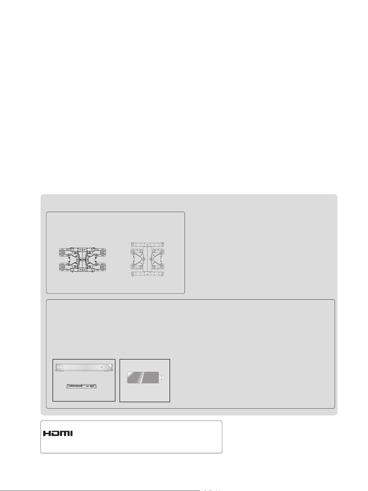
Separate purchase
Wall Mounting Bracket
LSW200B or
LSW200BG
(42LE8
***
)
47LE8
***
Optional extras can be changed or modified for quality improvement without any notification.
Contact your dealer for buying these items.
This device only works with compatible LG LED LCD TV.
Wireless Media Box
AV1 AV2
RGB
HDMI 1 HDMI 2 HDMI 3 HDMI 4
COM
WIRELESS
LSW400B or
LSW400BG
(55LE8
)
***
Wireless LAN for
Broadband/
DLNA Adaptor
WIRELESS
OUT
CONTROL
AN-WL100W
HDMI, the HDMI logo and High-Definition
Multimedia Interface are trademarks or registered trademarks of HDMI Licensing LLC.

CONTENTS
PREPARATION
Accessories.......................................................
Front Panel Controls.........................................
Back Panel Information.....................................
A-1
A-2
A-3
Stand Installation..............................................
A-4
Back Cover for Wire Arrangement....................
A-5
Swivel Stand.....................................................
A-5
Kensington Security System............................
A-6
Earthing............................................................
A-7
Desktop pedestal Installation...........................
A-7
Wall Mount: Horizontal Installation...................
A-7
Remote Control Key Functions........................
A-8
Magic Motion Remote Control Key Functions.
A-10
EXTERNAL EQUIPMENT SETUP
Antenna Connection ............................................1
Connecting with a Component cable ..................2
Connecting with an HDMI cable .........................3
Connecting with an HDMI to DVI cable ..............4
Usb setup ............................................................5
Connecting with AN RF Cable ............................5
Connecting with AN RCA cable ..........................6
Connecting with a D-sub 15 pin cable ................7
Headphone Setup ...............................................8
Digital audio out Setup ........................................9
External Equipment WIreless Connection ........10
Supported Display Resolution ...........................11
Screen Setup for PC mode ...............................13
Network setup ...................................................17
WATCHING TV / PROGRAMME CONTROL
RF Specification of the Magic Motion Remote
Control
...............................................................27
Registering the Magic Motion Remote Control .27
How to Use the Magic Motion Remote Control 28
Precautions to Take when Using the Magic
Motion Remote Control .....................................28
Pointer Menu Options .......................................29
Turning on the TV .............................................30
Initializing Setup ...............................................30
Programme Selection ........................................30
Volume Adjustment ...........................................30
Quick Menu .......................................................31
Home Menu .......................................................32
On Screen Menus Selection and adjustment ...33
Auto programme tuning ...................................35
Manual programme Tuning ...............................36
Programme Edit ...............................................39
BOOSTER(IN AIR DIGITAL MODE) .................42
Software Update ...............................................43
Picture/Sound test .............................................45
Signal Test .........................................................46
Product/service information...............................47
74...................................................... tseT krowteN
Simple Manual ..................................................48
Selecting the Programme List ...........................49
Selecting the favourite Programme List ............50
Input List ............................................................51
Input Label ........................................................52
SIMPLINK ..........................................................53
AV Mode ............................................................56
Initializing(Reset to original factory settings) ....57
Legal Notice ......................................................58
..................................................60
YOUTUBE .........................................................61
36......................................................... REHTAEWUCCA
PICASA .........................................................64
TO USE A BLUETOOTH
Bluetooth? ........................................................66
Setting the Bluetooth .........................................67
Bluetooth headset ............................................68
Remove the bluetooth device ...........................72
My Bluetooth Information ..................................73
Receiving photos from external Bluetooth device
...........................................................................74
Listening to the Musics from external Bluetooth
device ................................................................75
NETCAST
Netcast Menu
CONTENTS
I

CONTENTS
CONTENTS
TO USE A USB OR PC DEVICE
Connection Method ...........................................76
DLNA .................................................................78
Movie list ...........................................................82
Photo list ............................................................91
Music list ............................................................99
DivX Registration Code ...................................105
Deactivation .....................................................106
GAME/SCHEDULE
Infinite Sound ..................................................135
Balance ...........................................................136
TV Speakers On/ Off Setup ............................137
DTV Audio Setting (in digital mode only) ........138
Selecting Digital Audio out ..............................139
Audio Reset .....................................................140
Stereo/Dual Reception (In Analogue Mode Only) 141
-
-
NICAM Reception (In Analogue Mode Only) ...... 142
- Speaker Sound Output Selection ................142
ON-SCREEN MENU LANGUAGE/COUNTRY/
AREA SELECTION .........................................143
Language Sele
ction ........................................144
Game/Schedule ..............................................107
EPG(ELECTRONIC PROGRAMME
GUIDE)(IN DIGITAL MODE)
EPG(Electronic programme guide) .................111
Manual Timer ..................................................113
Extended Description ......................................114
Schedule List ...................................................115
PICTURE CONTROL
Picture Size (Aspect Ratio) Control ................116
Picture Wizard .................................................118
Energy Saving .................................................119
Preset Picture Settings ...................................120
Manual Picture Adjustment .............................121
Picture Improvement Technology ....................122
Expert Picture Control
Picture Reset ...................................................126
TruMotion ........................................................127
LED LOCAL DIMMING ...................................128
P
ower Indicator ...............................................129
MHEG Guide.................................................. 129
Mode Setting ...................................................130
Demo Mode .....................................................131
.....................................123
SOUND & LANGUAGE CONTROL
Auto Volume Leveler .......................................132
Clear Voice II ...................................................133
Preset Sound Settings-Sound Mode ..............134
Sound Setting Adjustment -User Mode ..........135
TIME SETTING
Clock Setup .....................................................146
Auto on/off time setting ...................................147
Sleep Timer setting .........................................148
PARENTAL CONTROL / RATINGS
Set Password & Lock System.........................149
Block Programme ............................................150
External Input Blocking ...................................151
Key Lock..........................................................152
TELETEXT
Switch on/off ...................................................153
SIMPLE Text....................................................153
TOP Text..........................................................154
FASTEXT ........................................................154
Special Teletext Functions ..............................155
APPENDIX
Troubleshooting ...............................................157
Maintenance ....................................................159
Product Specifications ...................................160
IR Codes .........................................................161
External Control Device Setup ........................162
Open source software notice ..........................170
II
PREPARATION
LIGHT
[
LIGHT
[
AV MODE INPUT
TV/
RAD
ENERGY
1 2
ABC3 DEF
4
GHI5 JKL6MNO
7
PQRS8 TUV
0
9
WXYZ
BACK
EXIT
OK
LIST
Q.VIEW
MENU
Q.MENU
GUIDE
T.OPT
P
A
G
E
MARK
RATIO
MUTE
P
SAVING
INFO
TEXT
FAV
DELETE
CHAR/NUM
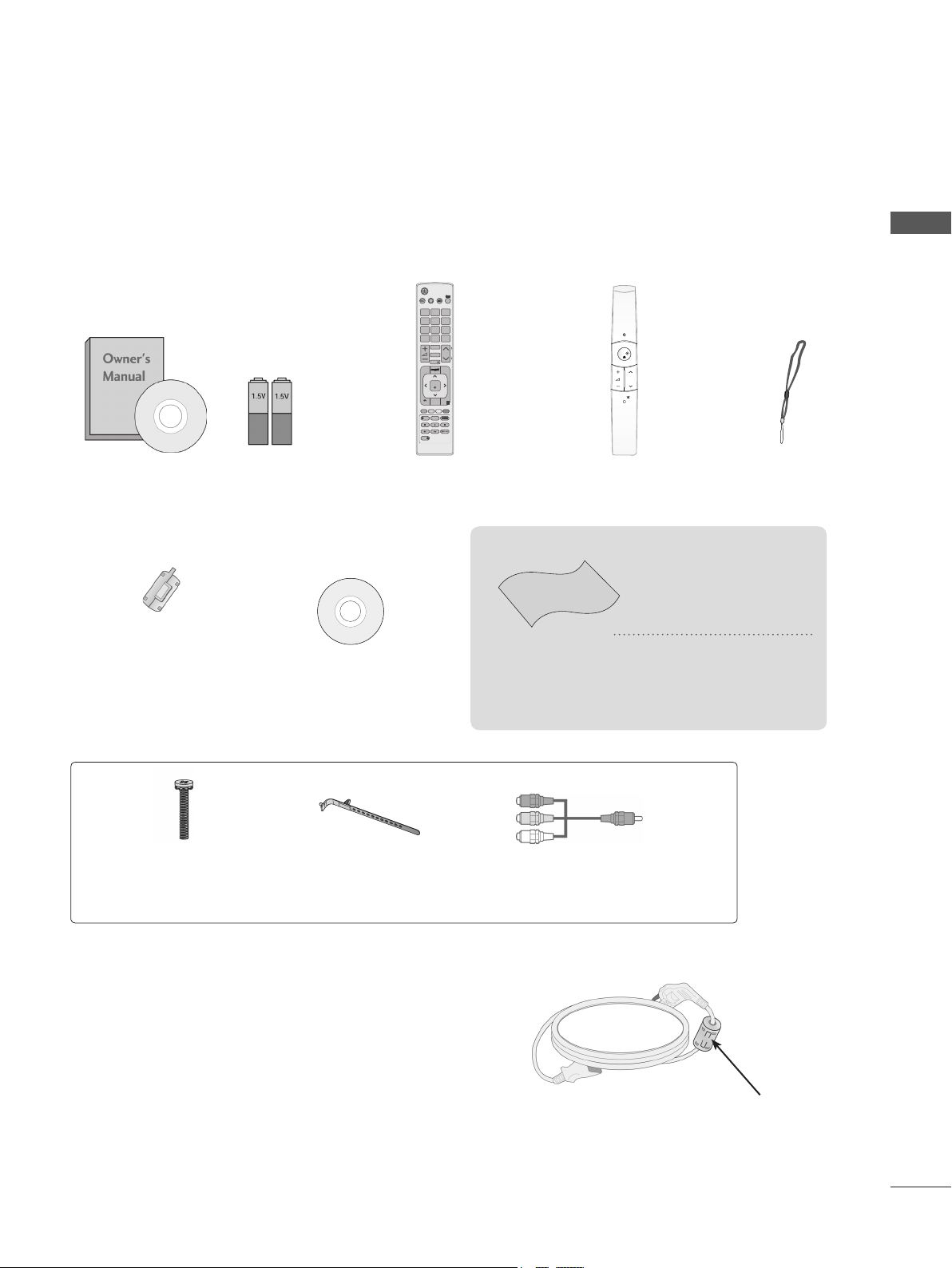
ACCESSORIES
Ensure that the following accessories are included with your TV. If an accessory is missing, please
contact the dealer where you purchased the TV.
■ Image shown may differ from your TV.
x 4
Owner’s Manual
Batteries
Remote Control
OK
P
MUTE
Motion Remote Control
Strap
(AAA x 2
AA x 2)
This item is not included for all models.
* Lightly wipe any stains or
fingerprints on the surface
of the TV with the polishing cloth.
Ferrite Core
(
This item is not included
for all models.
)
Nero MediaHome
4 Essentials CD
Polishing Cloth
Polishing cloth for
use on the screen.
Do not use excessive
force. This may cause
scratching or discolouration.
PREPARATION
x 8
x 2
(M4x20)
Bolts for stand assembly
Cable Holder
Component gender cable,
AV gender cable
Use of ferrite core (This feature is not available for all models.)
Ferrite core can be used to reduce the electromagnetic
wave when connecting the power cord.
The closer the location of the ferrite core to the power
plug, the better it is.
Install the power plug closely.
A-1
PREPARATION
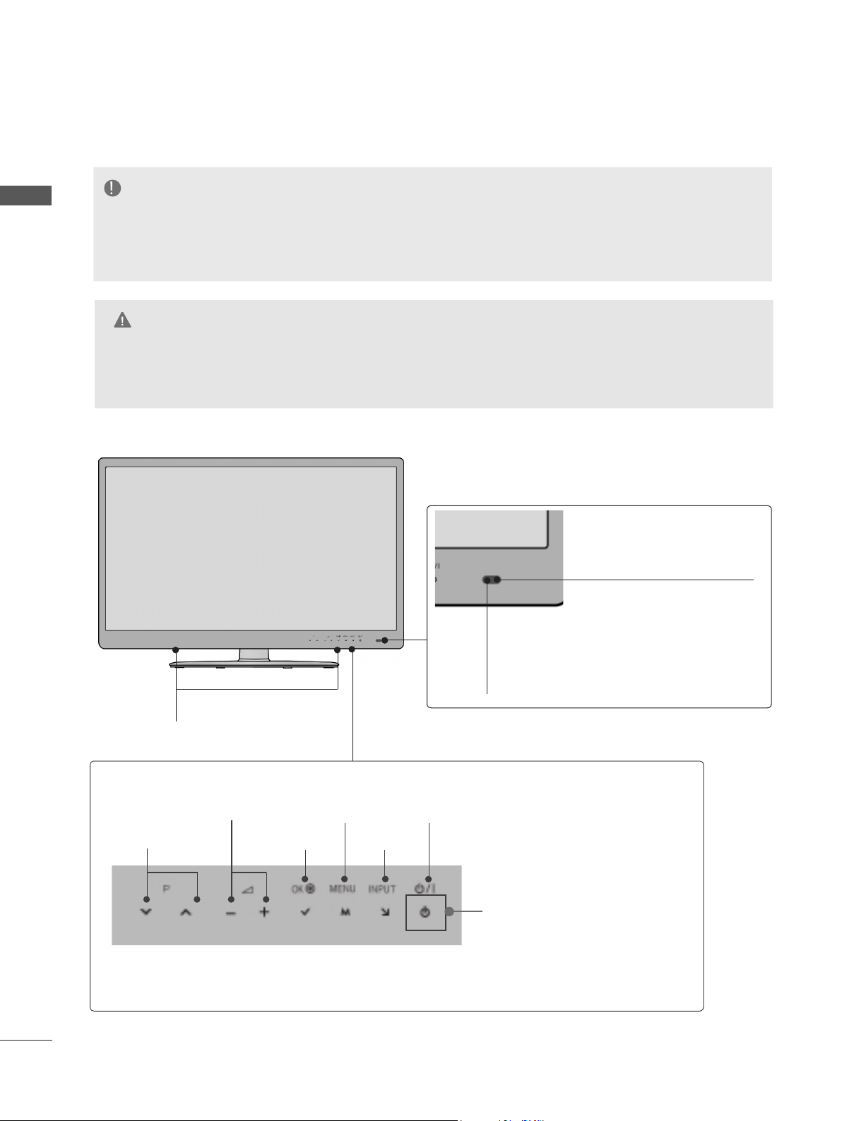
FRONT PANEL CONTROLS
NOTE
PREPARATION
►►TV can be placed in standby mode in order to reduce the power consumption.
The energy consumed during use can be significantly reduced if the level of
brightness of the picture is reduced, and this will reduce the overall running cost.
CAUTION
► Do not step on the glass stand or subject it to any impact. It may break, causing possible injury from frag-
ments of glass, or the TV may fall.
► Do not drag the TV. The floor or the product may be damaged.
■ Image shown may differ from your TV.
Intelligent Sensor
Adjusts picture according to
the surrounding conditions.
A-2
SPEAKER
Touch Button
You can use the desired button function by touching.
VOLUME
PROGRAMME
MENU
POWER
INPUTOK
Remote Control Sensor
Power/Standby Indicator
(Can be adjusted using the
Power Indicator
OPTION menu.)
in the
PREPARATION
USB IN 2
H/P
USB IN 1
HDMI
IN 4
AV IN2
VIDEO / AUDIO
COMPONENT IN2
AUDIO / Y P
B PR
USB IN 2
USB IN 1
B
P
R
WIRELESS
CONTROL
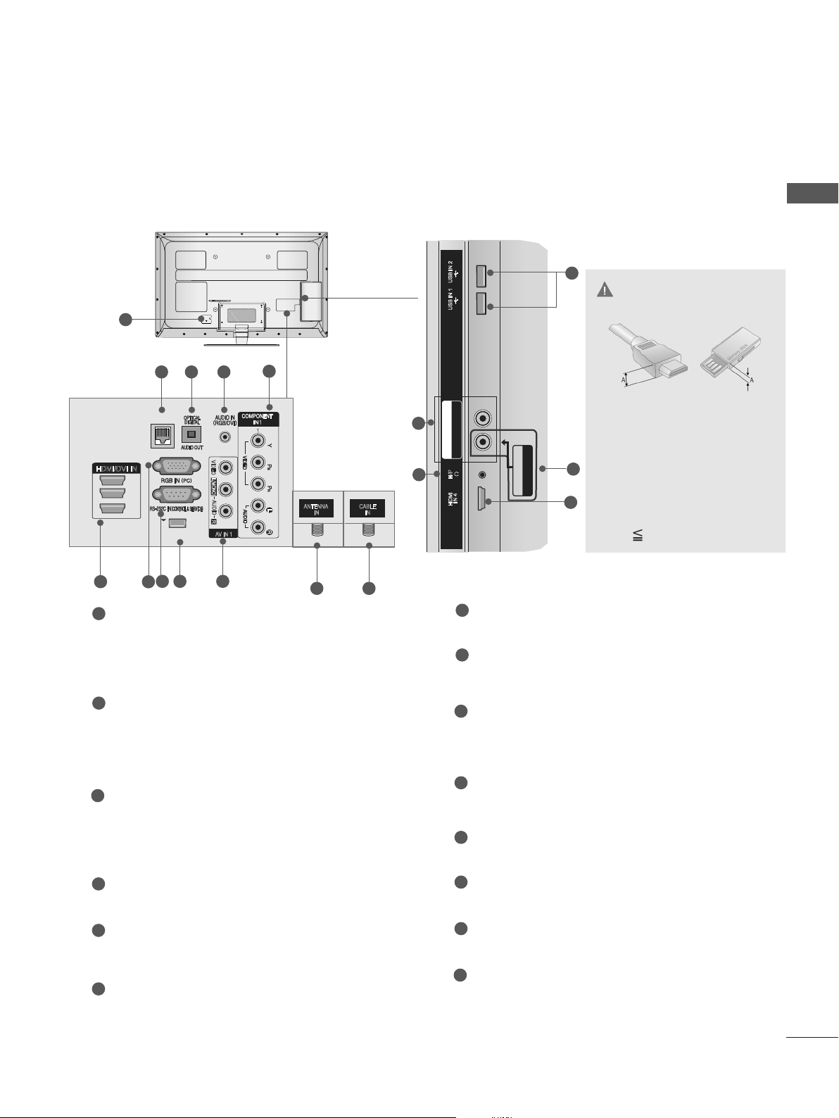
BACK PANEL INFORMATION
■ Image shown may differ from your TV.
1
5
1
1
ANTENNA
IN
11 12
LAN
HDMI/DVI IN
3
2
1
7
6
1
Power Cord Socket
8 9
432
VIDEO
L(MONO)
AUDIO
R
AV IN 1
10
This TV operates on an AC power. The voltage is indicated on the Specifications page.
(►
) Never attempt to operate the TV
p.160
on DC power.
2
LAN
Network connection for Accu Weather,
YouTube,Picasa, etc.
Also used for photo and music files on local
network.
3
OPTICAL DIGITAL AUDIO OUT
Connect digital audio to various types of
equipment.
Connect to a Digital Audio Component.
Use an Optical audio cable.
CABLE
IN
5
14
USB IN 2
13
CAUTION
USB IN 1
B PR
COMPONENT IN2
AUDIO / Y P
H/P
IN 4
HDMI
8
7
AV IN2
VIDEO / AUDIO
RGB IN Input
Connect the output from a PC.
RS-232C IN (CONTROL & SERVICE) PORT
Connect to the RS-232C port on a PC.
This port is used for Service or Hotel mode.
9
WIRELESS Control
Connect the Wireless Dongle to the TV to
control the external input devices connected
to Media Box wirelessly.
Audio/Video Input
10
Connect audio/video output from an external
device to these jacks.
Antenna Input
11
Connect antenna to this jack.
► Use a product with the fol-
10
6
lowing thickness for optimal
connection to HDMI cable
(Only HDMI IN 4) / USB
device.
*A 10 mm
PREPARATION
4
RGB/DVI Audio Input
Connect the audio from a PC.
5
Component Input
Connect a component video/audio device to
these jacks.
6
HDMI/DVI IN Input
Connect an HDMI signal to HDMI IN. Or DVI
(VIDEO) signal to HDMI/DVI port with DVI to
HDMI cable.
12
Cable Input
Connect cable signals to this jack.
13
USB Input
Connect USB storage device to this jack.
14
Headphone Socket
Plug the headphone into the headphone
socket.
A-3
PREPARATION
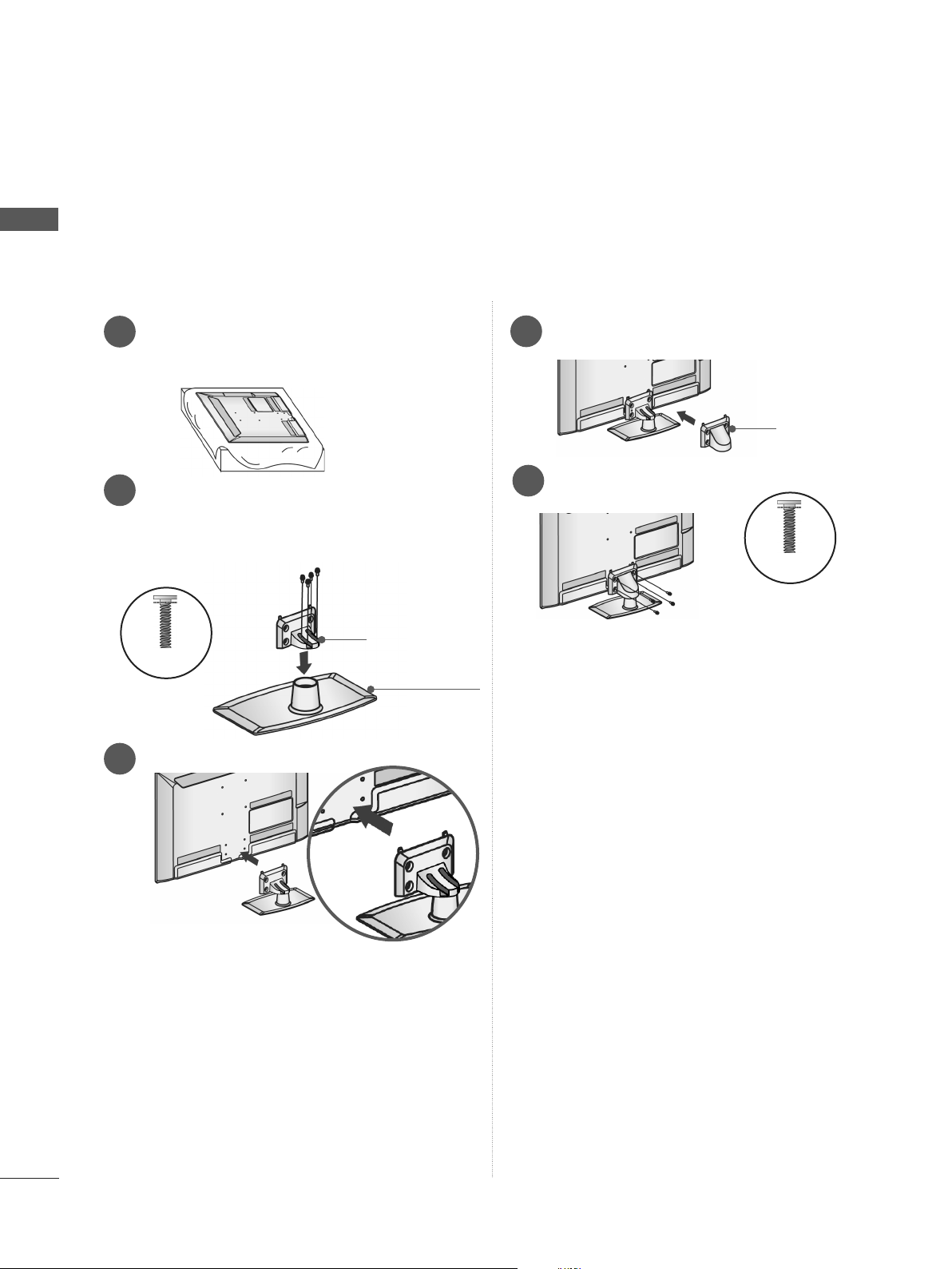
STAND INSTALLATION
■ Image shown may differ from your TV.
PREPARATION
When assembling the desk type stand, check whether the bolt is fully tightened. (If not tightened fully,
the product can tilt forward after the product installation.) If you tighten the bolt with excessive force,
the bolt can deviate from abrasion of the tightening part of the bolt.
Carefully place the TV screen side down
1
on a cushioned surface to protect the
screen from damage.
Assemble the parts of the Stand Body with
2
the Stand Base of the TV.
At this time, tighten the screws that hold the
Stand Body on.
Stand Body
M4 X 20
Stand Base
Assemble the TV as shown.
3
Assemble the parts of the Stand Rear
4
Cover with the TV.
Fix the 4 bolts securely using the holes in
5
the back of the TV.
M4 X 20
Stand Rear
Cover
A-4
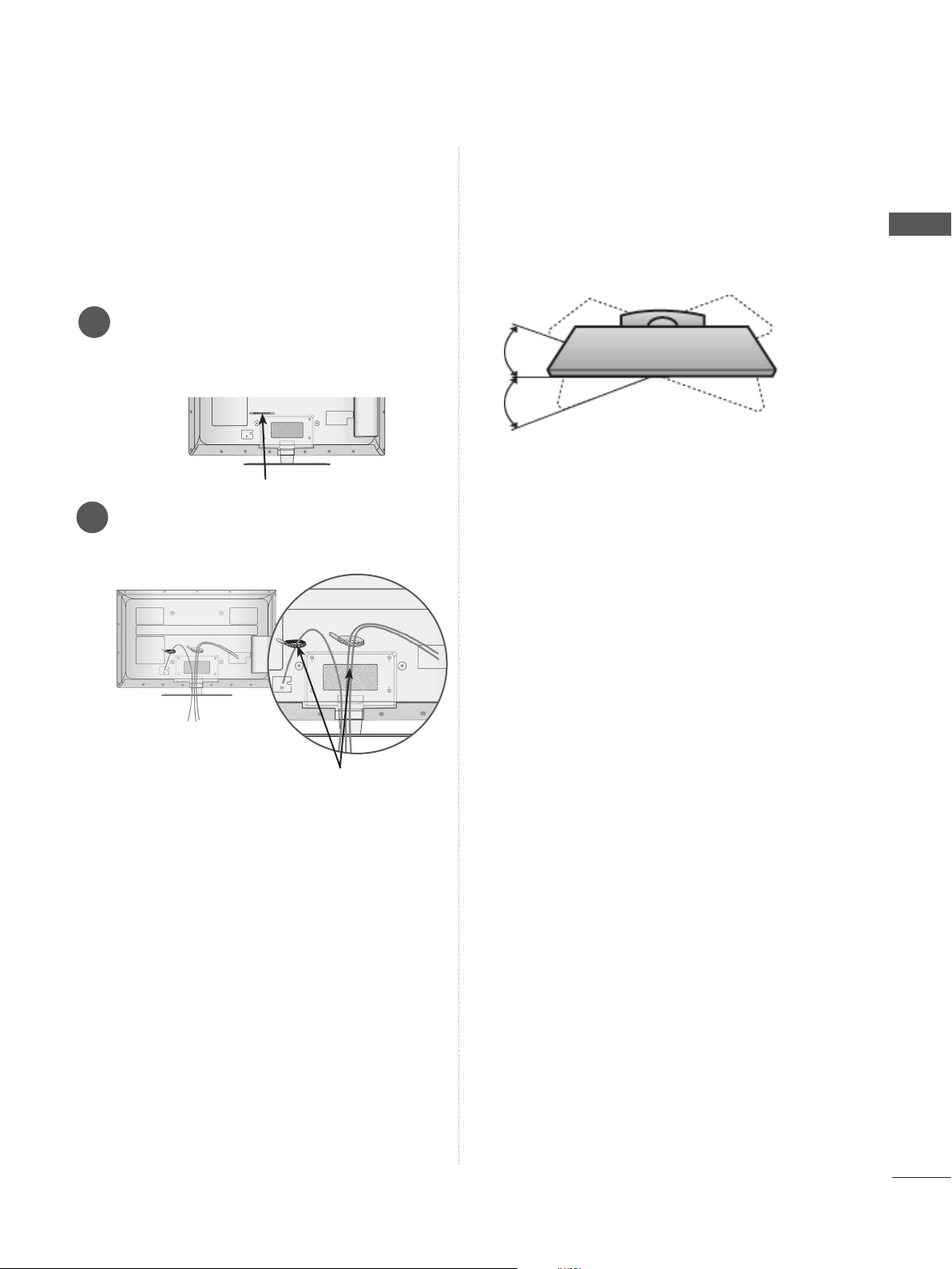
BACK COVER FOR
SWIVEL STAND
WIRE ARRANGEMENT
■ Image shown may differ from your TV.
Secure the power cord with the Cable
1
Holder on the TV back cover.
It will help prevent the power cable from
being removed by accident.
Cable Holder
After connecting the cables as necessary,
2
install Cable Holder as shown and bundle
the cables.
■ Image shown may differ from your TV.
After installing the TV, you can adjust the TV set
manually to the left or right direction by 20
degrees to suit your viewing position.
PREPARATION
Cable Holder
A-5
PREPARATION
PREPARATION
KENSINGTON SECURITY SYSTEM
■ This feature is not available for all models.
■ Image shown may differ from your TV.
The TV is equipped with a Kensington Security
System connector on the back panel. Connect
the Kensington Security System cable as shown
below.
For the detailed installation and use of the
Kensington Security System, refer to the user’s
guide provided with the Kensington Security
System.
For further information, contact http://www.kensington.com, the internet homepage of the
Kensington
company. Kensington sells security systems for
expensive electronic equipment such as notebook PCs and LCD projectors.
NOTE
► The Kensington Security System is an optional
accessory.
► If the TV feels cold to the touch, there may be a
small “flicker” when it is turned on.
This is normal
► Some minute dot defects may be visible on the
screen, appearing as tiny red, green, or blue
spots. However, they have no adverse effect on
the monitor's performance.
► Avoid touching the LCD screen or holding your
finger(s) against it for long periods of time.
Doing so may produce some temporary distortio
effects on the screen.
, there is nothing wrong with TV.
n
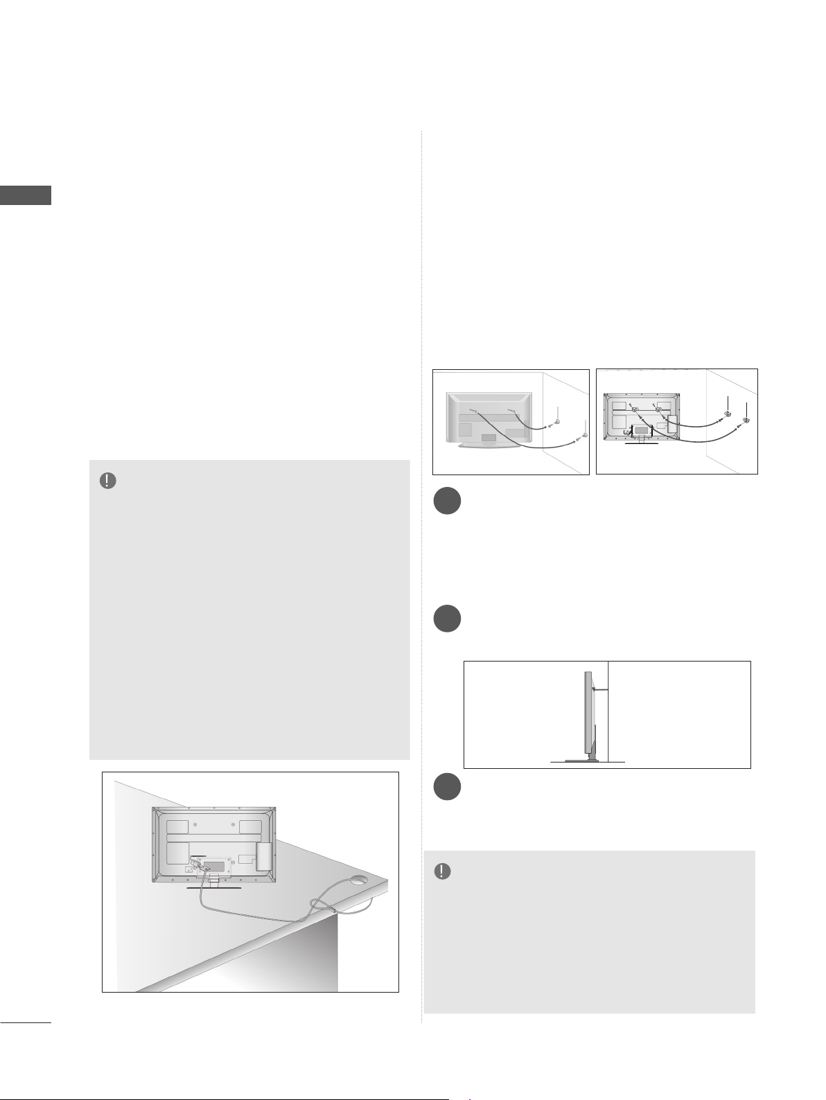
CAREFUL INSTALLATION ADVICE
■ You should purchase necessary components
to fix the TV safety and secure to the wall on
the market.
■ Position the TV close to the wall to avoid the
possibility of it falling when pushed.
■ The instructions shown below are a safer way
to set up the TV, by fixing it to the wall, avoiding the possibility of it falling forwards if pulled.
This will prevent the TV from falling forward
and causing injury. This will also prevent the
TV from damage. Ensure that children do not
climb or hang from the TV.
1
2
Use the eye-bolts or TV brackets/bolts to fix the
1
product to the wall as shown in the picture.
(If your TV has bolts in the eyebolts, loosen then
bolts.)
* Insert the eye-bolts or TV brackets/bolts and
tighten them securely in the upper holes.
Secure the wall brackets with the bolts on the
2
wall. Match the height of the bracket that is
mounted on the wall.
1
2
3
A-6
Use a sturdy rope to tie the product for align-
3
ment. It is safer to tie the rope so it becomes
horizontal between the wall and the product.
NOTE
► When moving the TV undo the cords first.
► Use a platform or cabinet strong and large
enough to support the size and weight of the TV.
► To use the TV safely make sure that the height of
the bracket on the wall and on the TV is the
same.
■ The TV can be installed in various ways such as
on a wall, or on a desktop etc.
■ The TV is designed to be mounted horizontally.
EARTHING
Ensure that you connect the earth wire to prevent
possible electric shock. If grounding methods are
not possible, have a qualified electrician install a
separate circuit breaker.
Do not try to earth the TV by connecting it to telephone wires, lightening rods or gas pipes.
Power
Supply
Circuit
breaker
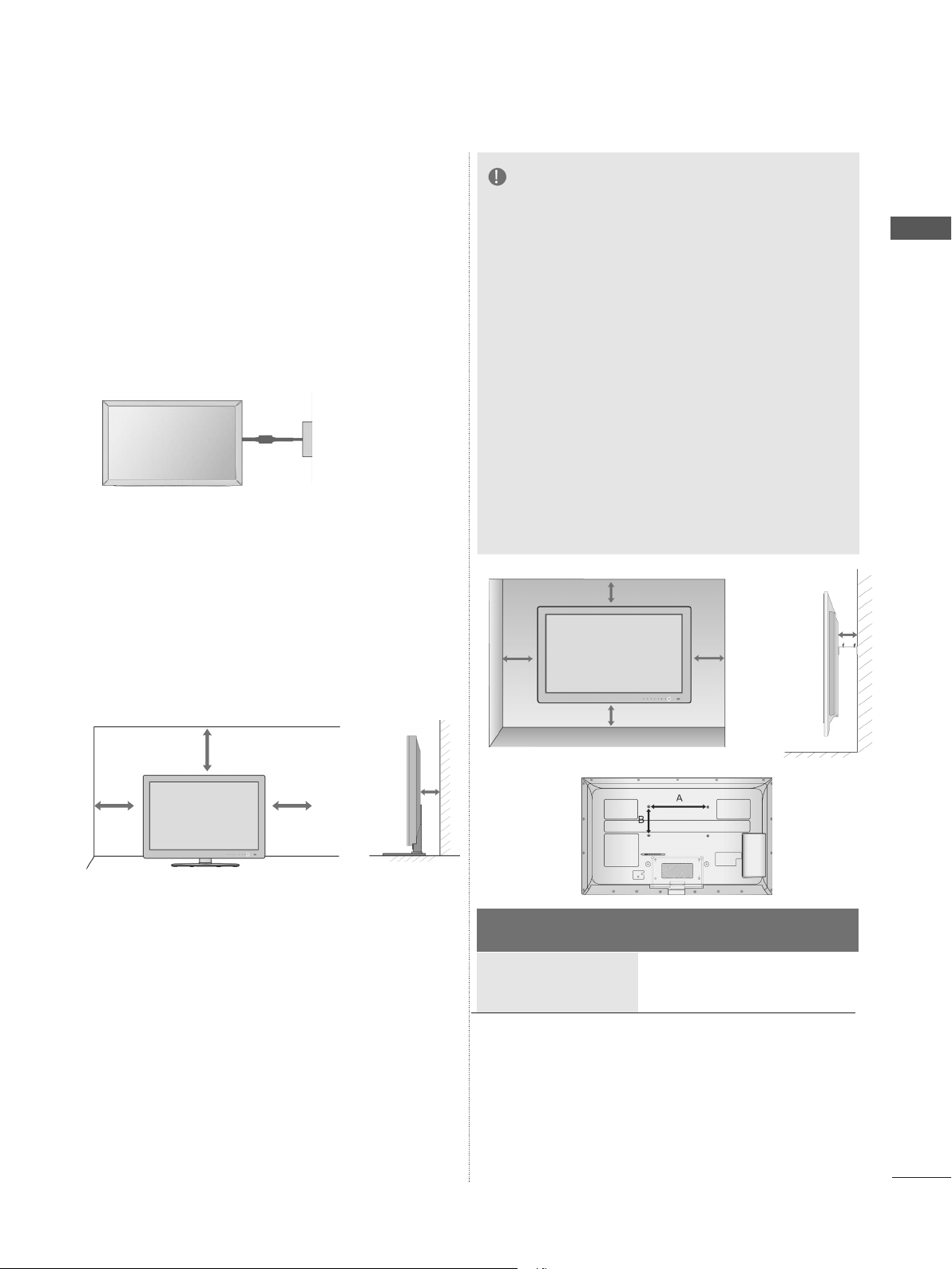
DESKTOP PEDESTAL INSTALLATION
■ Image shown may differ from your TV.
NOTE
►Should Install wall mount on a solid wall per-
pendicular to the floor.
►Should use a special wall mount, if you want
to install it to ceiling or slanted wall.
►The surface that wall mount is to be mount-
ed on should be of sufficient strength to support the weight of TV set; e.g. concrete, natural rock, brick and hollow block.
►Installing screw type and length depends on
the wall mount used. Further information,
refer to the instructions included with the
mount.
►LG is not liable for any accidents or damage
to property or TV due to incorrect installation:
- Where a non-compliant VESA wall mount
is used.
- Incorrect fastening of screws to surface
which may cause TV to fall and cause personal injury.
- Not following the recommended Installation
method.
10 cm
10 cm
10 cm
PREPARATION
10 cm
For adequate ventilation allow a clearance of 10
cm all around the TV.
10 cm
10 cm
10 cm
10 cm
WALL MOUNT: HORIZONTAL INSTALLATION
■ We recommend the use of a LG Brand wall
mounting bracket when mounting the TV to a wall.
■ We recommend that you purchase a wall mount-
ing bracket which supports VESA standard.
■ LG recommends that wall mounting be per-
formed by a qualified professional installer.
Model
42/47LE8
55LE8
***
***
10 cm
VESA
(A * B)
200 * 200 M6 4
400 * 400 M6 4
Standard
Screw
Quantity
A-7
PREPARATION
LIGHT
[
FAV
DELETE
CHAR/NUM
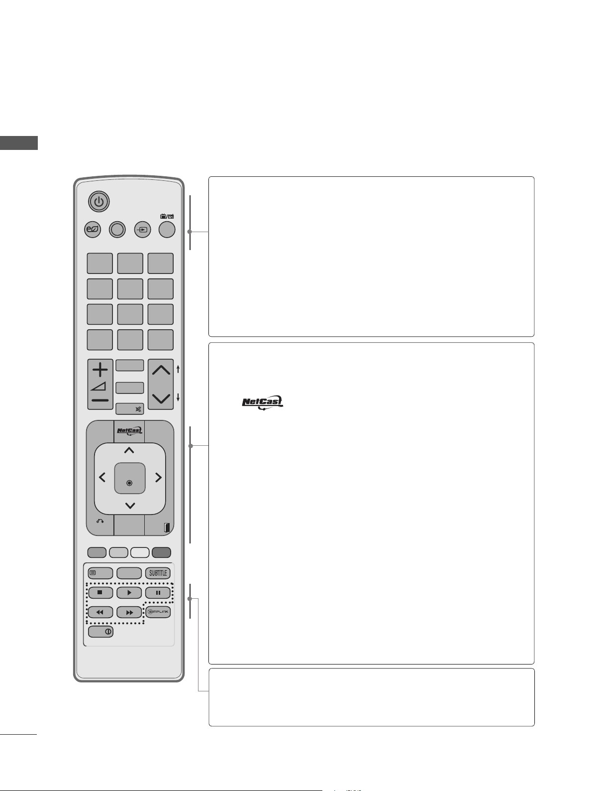
REMOTE CONTROL KEY FUNCTIONS
PREPARATION
When using the remote control, aim it at the remote control sensor on the TV.
Switches the TV on from standby or on to standby.
Adjust the Energy Saving mode of the TV.(►
It helps you select and set images and sounds
when connecting AV devices.(►
External input mode rotate in regular sequence.
Selects Radio, TV and DTV channel.
Selects a menu.
Clears all on-screen displays and returns to TV
(
►
viewing from any menu.
p.33)
Select the desired NETCAST menu source.
(AccuWeather, Picasa, YouTube etc.)
Select the desired quick menu source. (Aspect
Ratio, Clear Voice II , Picture Mode, Sound Mode,
Audio, Sleep Timer, Skip Off/On, USB Device).
(
►
p.31)
AV MODE INPUT
ENERGY
SAVING
1 2
4
GHI5 JKL6MNO
7
PQRS8 TUV
LIST
MENU
ABC3 DEF
0
MARK
RATIO
MUTE
OK
TV/
RAD
WXYZ
9
Q.VIEW
P
Q.MENU
P
A
G
E
POWER
ENERGY
SAVING
AV MODE
INPUT
TV/RAD
MENU
Q. MENU
p.119)
p.56)
A-8
BACK
TEXT
INFO
GUIDE
T.OPT
EXIT
BACK
GUIDE
EXIT
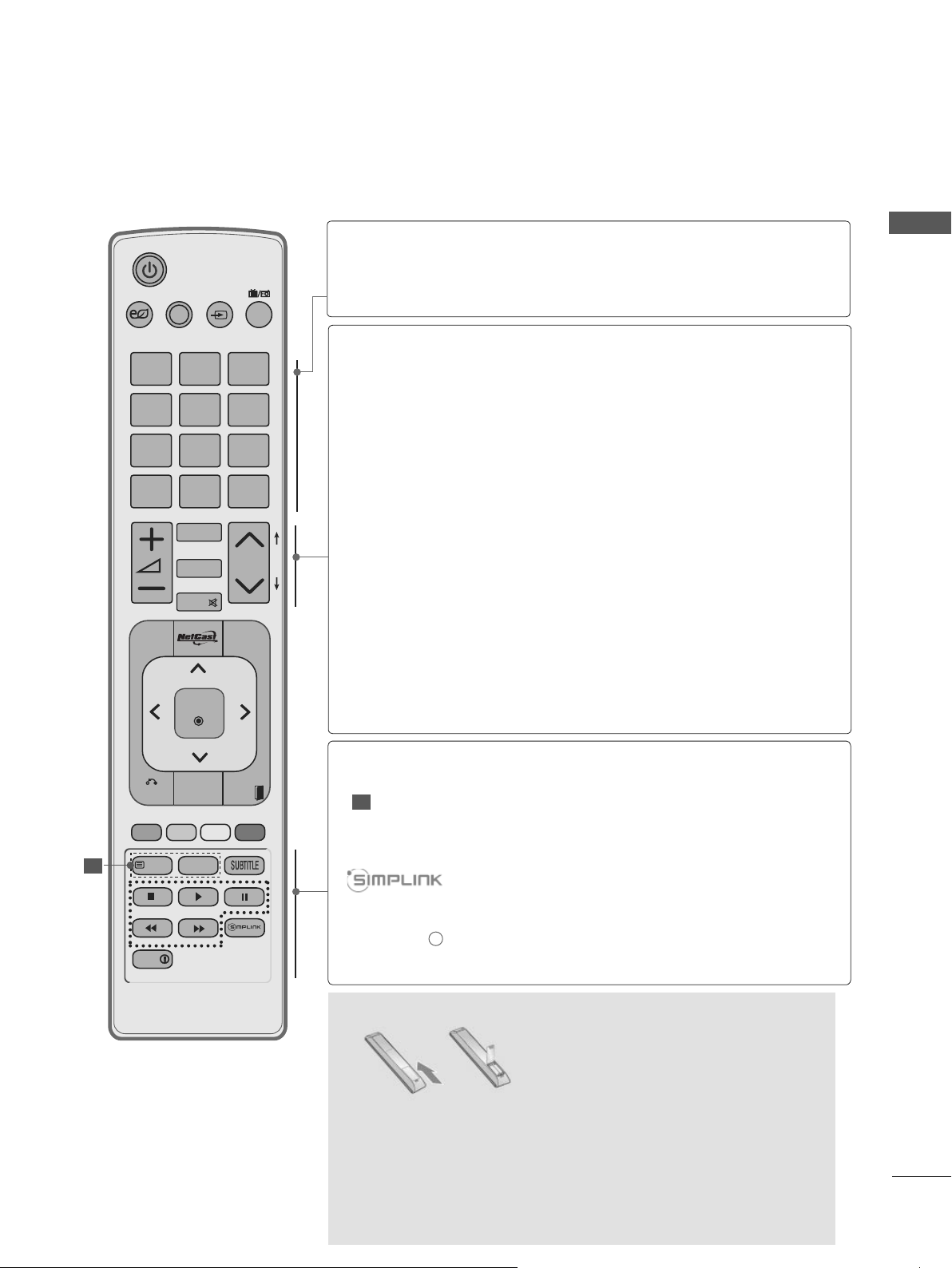
THUMBSTICK
(Up/Down/Left/Right)
OK
SIMPLINK /
MY MEDIA
Men u
control buttons
Allows the user to move return one step in an interactive application, EPG or other user interaction
function.
(
►
Shows programme schedule.
p.111)
Clears all on-screen displays and returns to TV
viewing from any menu.
Allows you to navigate the on-screen menus and
adjust the system settings to your preference.
Accepts your selection or displays the current mode.
Controls SIMPLINK or MY MEDIA menu (Photo List,
Music List and Movie List).
LIGHT
[
Installing Batteries
■ Open the battery compartment cover on the back and install
the batteries matching correct polarity (+with +,-with -).
■ Install two 1.5V AAA batteries. Do not mix old or used batter-
ies with new ones.
■ Close cover.
■ To remove the batteries, perform the installation actions in
reverse.
AV MODE INPUT
TV/
RAD
ENERGY
1 2
ABC3 DEF
4
GHI5 JKL6MNO
7
PQRS8 TUV
0
9
WXYZ
BACK
EXIT
OK
LIST
Q.VIEW
MENU
Q.MENU
GUIDE
T.OPT
P
A
G
E
MARK
RATIO
MUTE
P
SAVING
INFO
TEXT
1
FAV
DELETE
CHAR/NUM
0~9 number
button
Q.VIEW
VOLUME UP
Selects a programme.
Selects numbered items in a menu.
LIST
Displays the programme table.
Returns to the previously viewed programme.
Adjusts the volume.
PREPARATION
/DOWN
FAV
Displays the selected favourite programme.
MARK
Select the input to apply the Picture Wizard
settings.
Check and un-check programmes in the USB
RATIO
CHAR/NUM
MUTE
menu.
Selects your desired
p.116)
(►
S
hifts the Character or Number for NetCast TV
Aspect Ratio of picture.
menu.
Switches
the sound on or off.
DELETE
Programme
Delete the character when input the character.
Selects a programme.
UP/DOWN
PAGE UP/
DOWN
Coloured
buttons
DIGITAL These buttons are used for digital teletext.
1
TELETEXT
SUBTITLE
Move from
one full set of screen information to the
next one.
These buttons are used for teletext (on TELETEXT
models only), Programme edit.
For further details, see the ‘Digital Teletext’ sectio n.(
►
p.153
Recalls your preferred subtitle in digital mode.
)
See a list of AV devices connected to TV.
When you toggle this button, the Simplink menu
appears at the screen.
INFO i
Shows the present screen information.
A-9
PREPARATION
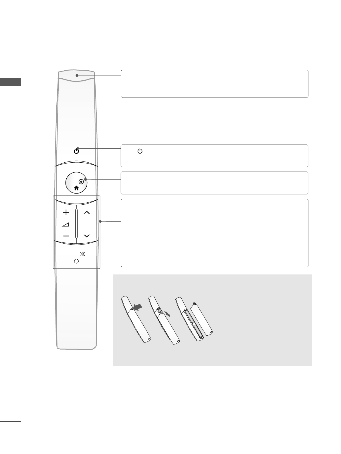
Switches the TV on from standby or on to standby.
MAGIC MOTION REMOTE CONTROL KEY FUNCTIONS
PREPARATION
OK
Pointer
Receiver
P
POWER
HOME MENU
VOLUME UP
/DOWN
Programme
UP/DOWN
Blinks the blue when operating.
Appears the pointer.
OK/
Adjusts the volume.
Selects a programme.
A-10
MUTE
MUTE
Switches the sound on or off.
Installing Batteries
■ Open the battery compartment
cover on the back and install the
batteries matching correct polarity (+with +,-with -).
■ Install two 1.5V AA batteries. Do
not mix old or used batteries
with new ones.
■ Close cover.
■ To remove the batteries, perform
the installation actions in
reverse.
RF Specification of the Magic Motion Remote Control
The Magic Motion Remote Control communicates with your TV by using a 2.4 GHz
bandwidth radio frequency (RF).
■ Output: 1 dBm or lower
■ Maximum Communication Distance: 10 m (30 ft) in an open space
■ Bandwidth: 2.4 GHz (2.4035 GHz - 2.4783 GHz)
■ Transfer Rate: 250 kbps
EXTERNAL EQUIPMENT SETUP
CABLE
IN
USB IN 2
H/P
USB IN 1
HDMI
IN 4
AV IN2
VIDEO / AUDIO
COMPONENT IN2
AUDIO / Y P
B PR
CABLE
IN
USB IN 2
H/P
USB IN 1
HDMI
IN 4
AV IN2
VIDEO / AUDIO
COMPONENT IN2
AUDIO / Y P
B
P
R
RF Coaxial Wire (75 ohm)
■ To prevent damage do not connect to the mains outlet until all connections are made between the
devices.
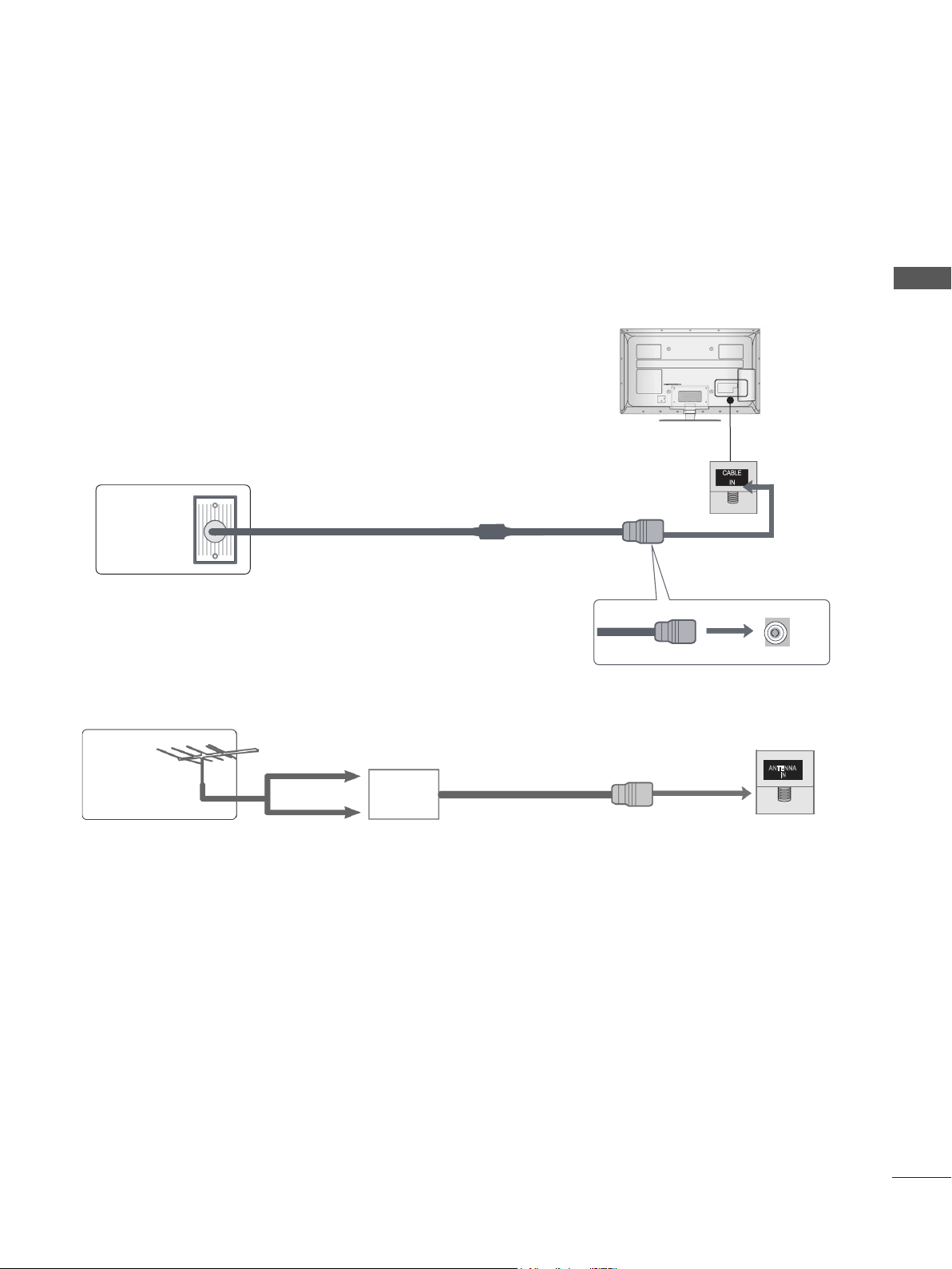
ANTENNA CONNECTION
■ For optimum picture quality, adjust antenna direction.
■ An antenna cable and converter are not supplied.
Multi-family Dwellings/Apartments
Wall
Antenna
Socket
(Connect to wall antenna socket)
EXTERNAL EQUIPMENT SETUP
UHF
ANTENNA
Antenna
Signal
Amplifier
IN
VHF
■ In poor signal areas, to achieve better picture quality it may be necessary to install a signal amplifier
to the antenna as shown above.
■ If signal needs to be split for two TVs, use an antenna signal splitter for connection.
1
EXTERNAL EQUIPMENT SETUP
CABLE
IN
USB IN 2
USB IN 1
*COMPONENT IN2 jack is just composed by an
integrated video jack and an integrated audio
jack. And the integrated audio jack also can be
used as the AV IN2 jack.
Once you connected the integrated audio jack,
the AV2 connection remind OSD will display,
if you just need it as the component Audio jack,
please choose No.
WIRELESS
CONTROL
■ To avoid damaging any equipment, never plug in any power cord until you have finished connecting
all equipment.
■ Image shown may differ from your TV.
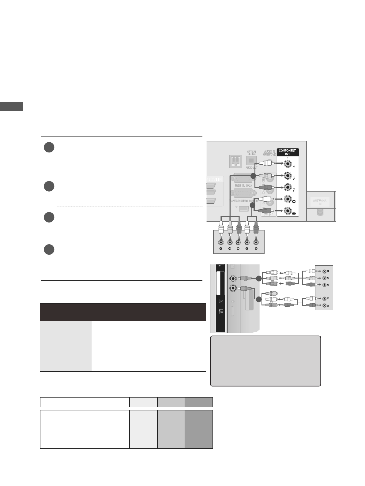
CONNECTING WITH A COMPONENT CABLE
EXTERNAL EQUIPMENT SETUP
This TV can receive Digital RF/Cable signals without an external digital set-top box. However, if you do
receive Digital signals from a digital set-top box or other digital external device, refer to the diagram as
shown below.
)
Connect the video outputs (Y, PB, PR
1
external equipment (digital set-top box, DVD,
etc.) to the COMPONENT IN VIDEO jacks on
the TV.
Connect the audio output of the external equip-
2
ment (digital set-top box, DVD, etc.) to the
COMPONENT IN AUDIO jacks on the TV.
Turn on the external equipment.
3
(
Refer to the external equipment's manual for
of the
LAN
VIDEO
1
3
2
1
L(MONO)
AUDIO
2
R
AV IN 1
1
1
ANTENNA
operating instructions.)
Select the input source using the
4
INPUT button on the remote control.
If connected to COMPONENT IN 2, select
Component2 input source.
► HDMI Audio Supported format : Dolby Digital, PCM.
DTS Audio format is not supported.
Signal Component HDMI
Component1
B PR
COMPONENT IN2
AUDIO / Y P
H/P
IN 4
HDMI
or
AV IN2
1
2
VIDEO / AUDIO
IN
2
480i/576i O X
480p/576p O O
720p/1080i O O
1080p
(50 Hz / 60 Hz only)
O
Component Input ports
O
(24 Hz / 30 Hz /
50 Hz / 60 Hz)
To achieve better picture quality, connect a DVD player to the component input ports as shown below.
Component ports on the TV Y PB PR
B PR
Video output ports
on DVD player
Y P
Y B-Y R-Y
Y Cb Cr
Y Pb Pr
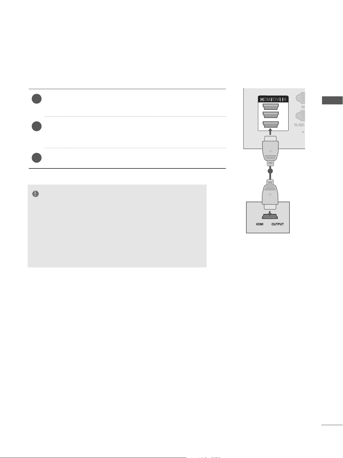
CONNECTING WITH AN HDMI CABLE
CONTROL
L(MONO)
R
AUDIO
VIDEO
AV IN 1
LAN
1
1
ANTENNA
IN
CABLE
IN
Connect the HDMI output of the external equipment (digital set-
1
top box, DVD, etc.) to
DVI IN 3 or HDMI IN 4
Turn on the external equipment.
2
HDMI/DVI IN 1 HDMI/DVI IN 2 HDMI/
, ,
jack on the TV.
(Refer to the external equipment's manual for operating
instructions.)
Select input source using the
3
INPUT button on the remote control.
HDMI1, HDMI2, HDMI3 or HDMI4
NOTE
►The TV can receive video and audio signals simultaneously
when using an HDMI cable.
►If the DVD does not support Auto HDMI, you must set the
output resolution appropriately.
►Check that your HDMI cable is High Speed HDMI Cable. If
the HDMI cables are not High Speed HDMI Cable, flickering
or no screen display can result. Please use the High Speed
HDMI Cable.
HDMI/DVI IN
1
3
2
1
EXTERNAL EQUIPMENT SETUP
3
EXTERNAL EQUIPMENT SETUP
CONTROL
L(MONO)
R
AUDIO
VIDEO
AV IN 1
LAN
1
1
ANTENNA
IN
CABLE
IN
1
2
3
HDMI/DVI IN
CABLE
IN
WIRELESS
CONTROL
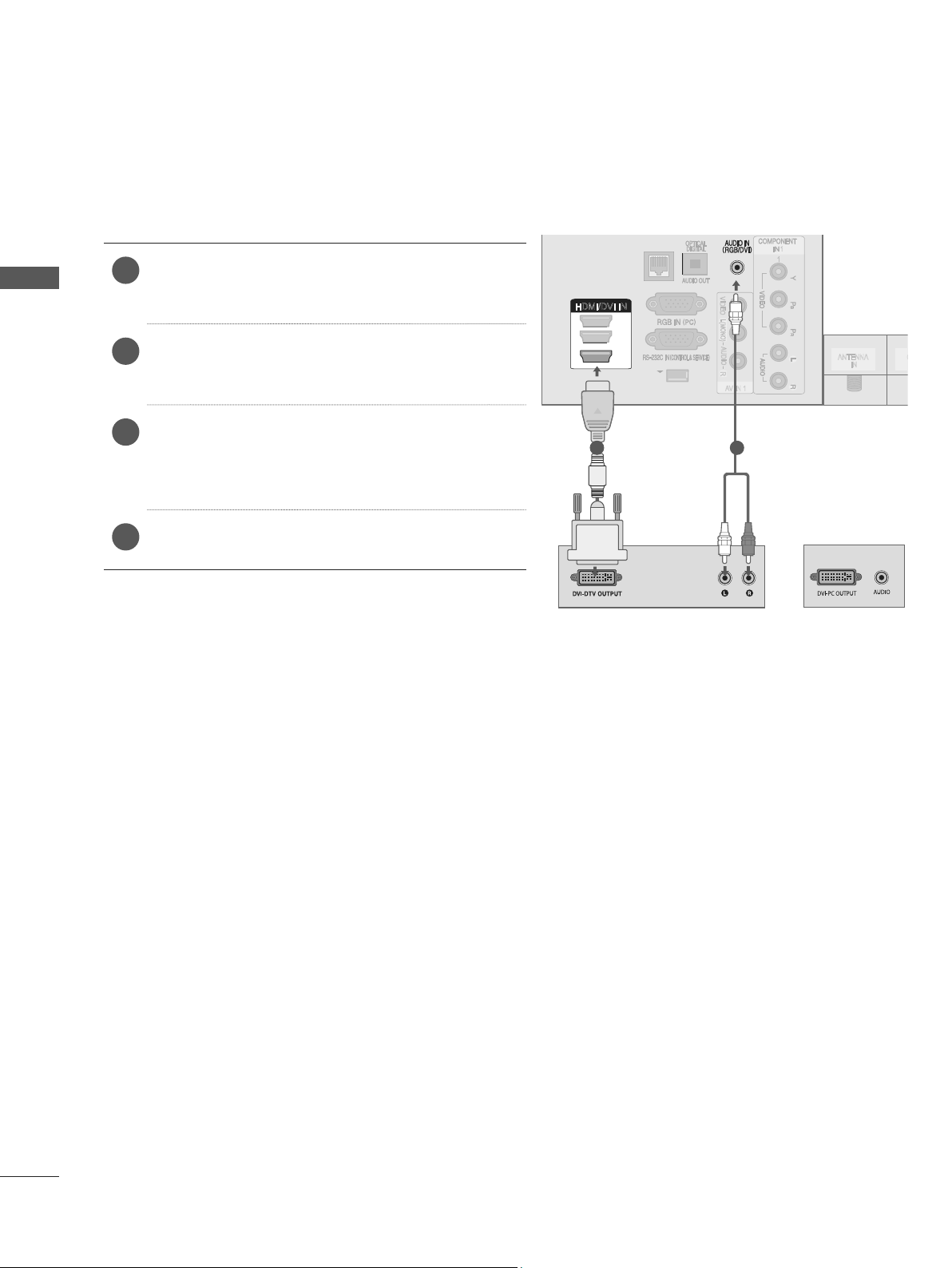
CONNECTING WITH AN HDMI TO DVI CABLE
EXTERNAL EQUIPMENT SETUP
LAN
Connect the digital set-top box or the DVI out-
1
put of the PC to
HDMI/DVI IN 3
Connect the audio output of the digital set-top
2
box or the PC audio output to the AUDIO IN
(RGB/DVI) jack on the TV.
3
Turn on the digital set-top box or the PC and
the TV.
(
Refer to the digital set-top box or the PC
HDMI/DVI IN 1,HDMI/DVI IN 2 or
jack on the TV.
-
HDMI/DVI IN
3
2
1
1 2
VIDEO
L(MONO)
AUDIO
R
AV IN 1
1
1
ANTENNA
IN
manual for operating instructions.)
Select
4
the
HDMI1,HDMI2 or HDMI3
INPUT
button on the remote control.
input source using
or
4
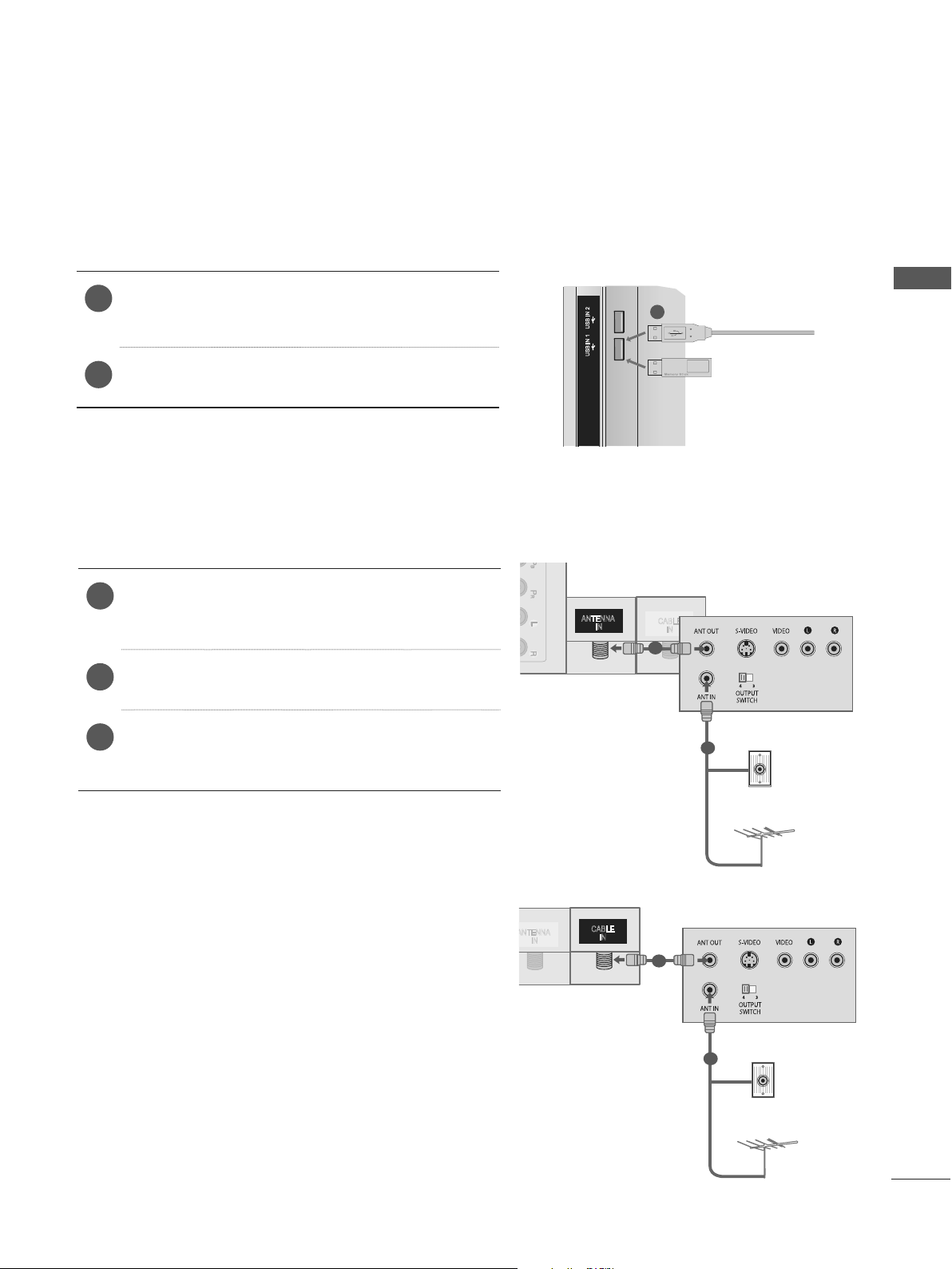
USB SETUP
1
ANTENNA
IN
CABLE
IN
USB IN 1 or
►
p.76)
USB IN 2
USB IN 1
1
Connect the USB device to the
1
USB IN 2
After connecting the
2
jack, you use the USB function. (
jack on the TV.
USB IN 1 or USB IN 2
CONNECTING WITH AN RF CABLE
To avoid picture noise (interference), allow adequate distance between the VCR and TV.
Connect the ANT OUT socket of the VCR to
1
the ANTENNA IN / CABLE IN socket on the
TV.
Connect the antenna cable to the ANT IN
2
socket of the VCR.
Press the PLAY button on the VCR and match
3
the appropriate channel between the TV and
VCR for viewing.
ANTENNA
IN
CABLE
1
IN
EXTERNAL EQUIPMENT SETUP
or
Wall Jack
2
CABLE
A
IN
IN
1
Antenna
Wall Jack
2
Antenna
5
EXTERNAL EQUIPMENT SETUP
ANTENNA
IN
CABLE
IN
USB IN 2
USB IN 1
WIRELESS
CONTROL
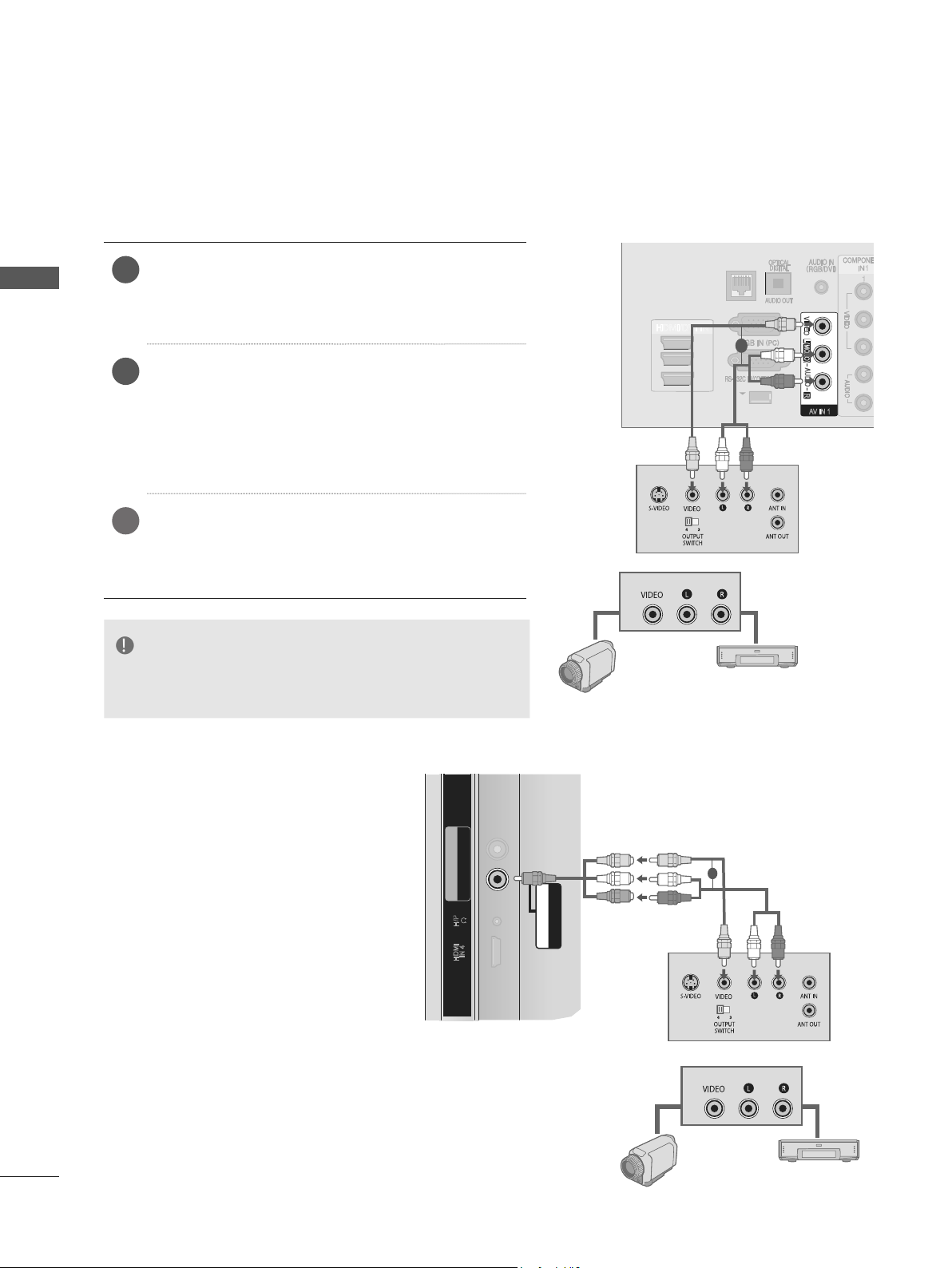
CONNECTING WITH AN RCA CABLE
EXTERNAL EQUIPMENT SETUP
Connect the AUDIO/VIDEO jacks between TV
1
and VCR or external equipment. Match the
jack colours (Video = yellow, Audio Left =
white, and Audio Right = red)
Insert a video tape into the VCR and press
2
PLAY on the VCR. (Refer to the VCR owner’s
manual.)
Or, Operate the corresponding external equipment.
(Refer to external equipment operating guide.)
Select AV1 input source using the INPUT but-
3
ton on the remote control.
If connected to AV IN 2, select AV2 input
source.
NOTE
► If you have a mono VCR, connect the audio cable from
the VCR to the AUDIO L/MONO jack of the TV.
Camcorder
HDMI/DVI IN
3
2
1
or
Video Game Set
LAN
1
1
VIDEO
1
L(MONO)
AUDIO
R
AV IN 1
or
B PR
1
COMPONENT IN2
AUDIO / Y P
H/P
HDMI
IN 4
AV IN2
VIDEO / AUDIO
or
Video Game Set
6
Camcorder
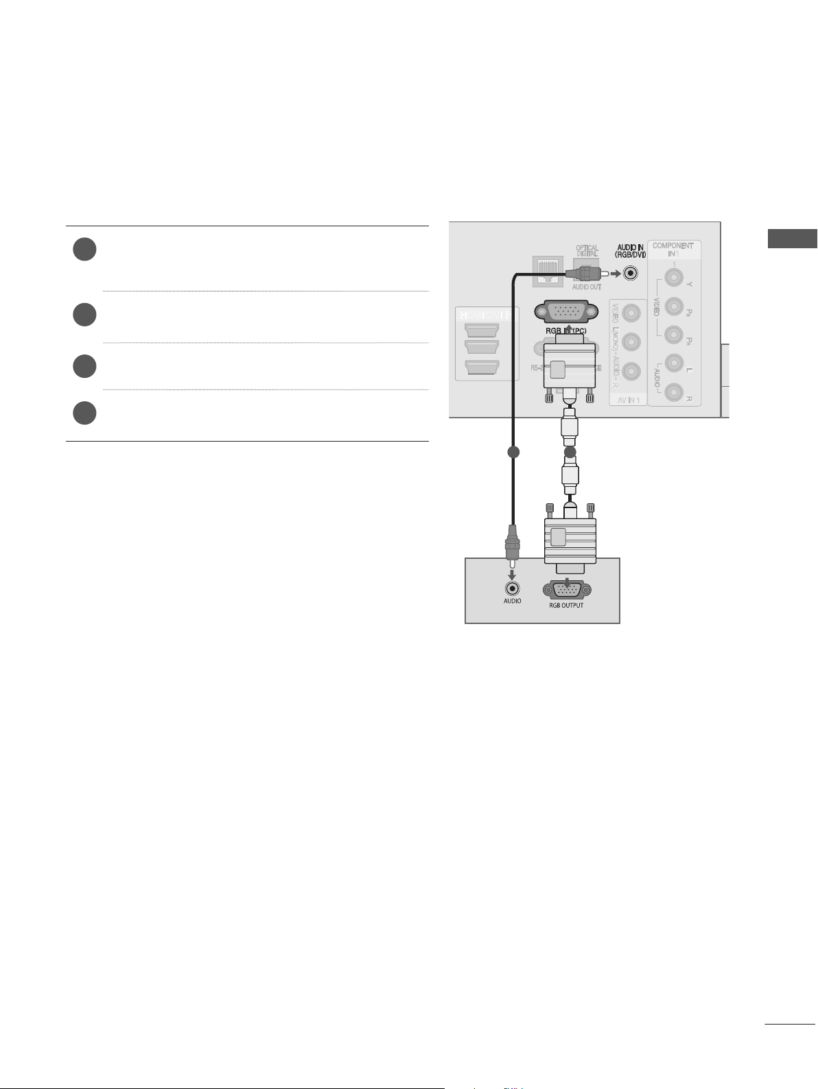
CONNECTING WITH A D-SUB 15 PIN CABLE
ANTENNA
IN
CABLE
IN
This TV provides Plug and Play capability, meaning that the PC adjusts automatically to the TV's settings.
Connect the RGB output of the PC to the RGB
1
IN (PC) jack on the TV.
Connect the PC audio output to the AUDIO IN
2
(RGB/DVI) jack on the TV.
Turn on the PC and the TV
3
Select RGB input source using the INPUT but-
4
ton on the remote control.
HDMI/DVI IN
LAN
3
2
1
2 1
CONTROL
VIDEO
L(MONO)
AUDIO
R
AV IN 1
1
1
EXTERNAL EQUIPMENT SETUP
7
EXTERNAL EQUIPMENT SETUP
USB IN 2
USB IN 1
AUDIO
COMPONENT IN2
AUDIO / Y P
B PR
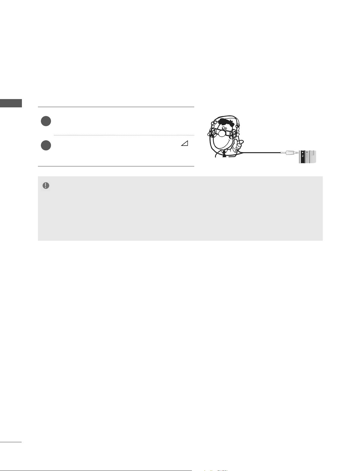
HEADPHONE SETUP
You can listen the sound through the headphone.
EXTERNAL EQUIPMENT SETUP
Plug the headphone into the headphone socket.
1
To adjust the headphone volume, press the
2
+ or - button. If you press the MUTE button,
the sound from the headphone is switched off.
NOTE
► AUDIO menu items are disabled when connecting a headphone.
► When changing AV MODE with a headphone connected, the change is applied to video but not to audio.
► Optical Digital Audio Out is not available when connecting a headphone.
► Headphone impedance: 16 Ω
► Max audio output of headphone: 10 mW to 15 mW
H/P
AV IN2
VIDEO /
IN 4
HDMI
8
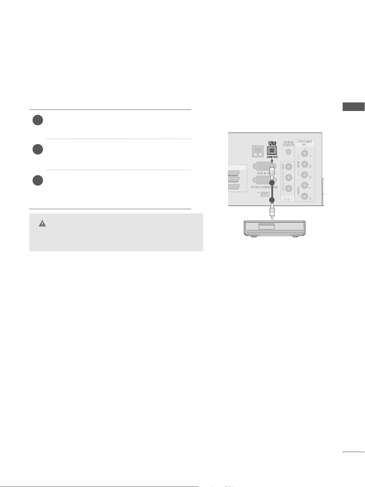
DIGITAL AUDIO OUT SETUP
ANTENNA
IN
CABLE
IN
Sending the TV’s audio signal to external audio equipment via the Digital Audio Output (Optical) port.
If you want to enjoy digital broadcasting through 5.1-channel speakers, connect the OPTICAL
DIGITAL AUDIO OUT terminal on the back of TV to a Home Theater (or amp).
Connect one end of an optical cable to the TV
1
Digital Audio (Optical) Output port.
EXTERNAL EQUIPMENT SETUP
Connect the other end of the optical cable to
2
the digital audio (Optical) input on the audio
equipment.
Set the “TV Speaker option - Off ” in the
3
AUDIO menu.(
►
). Refer to the external
p.137
audio equipment instruction manual for operation.
CAUTION
► Do not look into the optical output port. Looking at the laser
beam may damage your vision.
LAN
VIDEO
3
2
1
WIRELESS
CONTROL
L(MONO)
AUDIO
1
R
AV IN 1
2
1
1
9
EXTERNAL EQUIPMENT SETUP
ANTENNA
IN
CABLE
IN
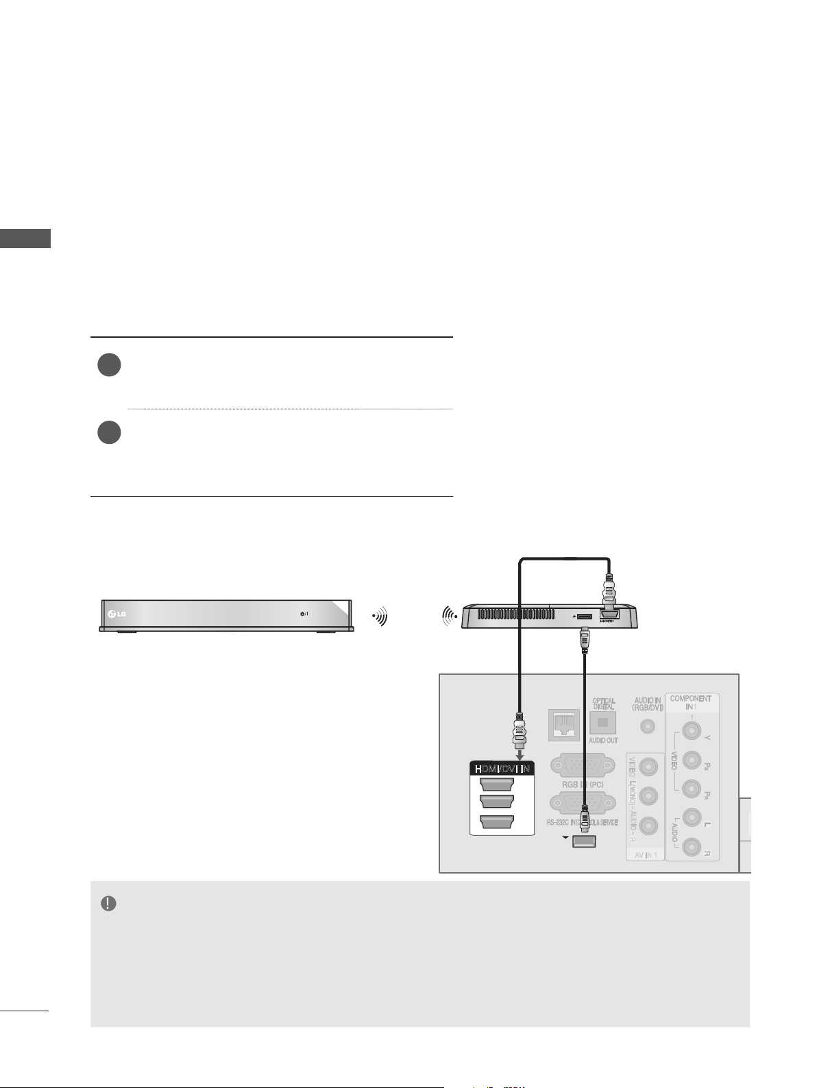
EXTERNAL EQUIPMENT WIRELESS CONNECTION
LG TVs with a Wireless Control port support the LG Wireless Media Box, which is sold
separately. When you connect the Wireless Ready Dongle (included with the Wireless Media Box) to the
TV, external devices can be connected to the LG Wireless Media Box and video and audio will be sent to
the TV wirelessly.
EXTERNAL EQUIPMENT SETUP
After the wireless is connected, press the INPUT button to view the wireless input screen.
Refer to the Wireless Media Box manual for operating instructions.
Connect the WIRELESS CONTROL jack of the
1
Wireless Ready Dongle to the WIRELESS
CONTROL jack on the TV.
Connect HDMI OUT jack of the Wireless
2
Ready Dongle to the HDMI/DVI IN 1, HDMI/
DVI IN 2, HDMI/DVI IN 3 or HDMI IN 4 jack on
the TV.
AV1 AV2
RGB
COM
HDMI 1 HDMI 2 HDMI 3 HDMI 4
WIRELESS
WIRELESS
CONTROL
OUT
LG Wireless Media Box
10
LAN
1
VIDEO
HDMI/DVI IN
3
2
1
WIRELESS
WIRELESS
CONTROL
CONTROL
L(MONO)
AUDIO
R
AV IN 1
NOTE
►WIRELESS CONTROL : Wireless Ready Dongle power supply and control usage.
►HDMI : Video/Audio signal is connected in Wireless Ready Dongle.
►When you connect to the Wireless Media Box (Separately sold product), you can watch the
external device connected to the Wireless Media Box through wireless connection.
► When using the external device connected to the Wireless Media Box, some functions of the TV.
► In wireless external output, Real Cinema and Digital Noise Reduction functions are not supported.
1
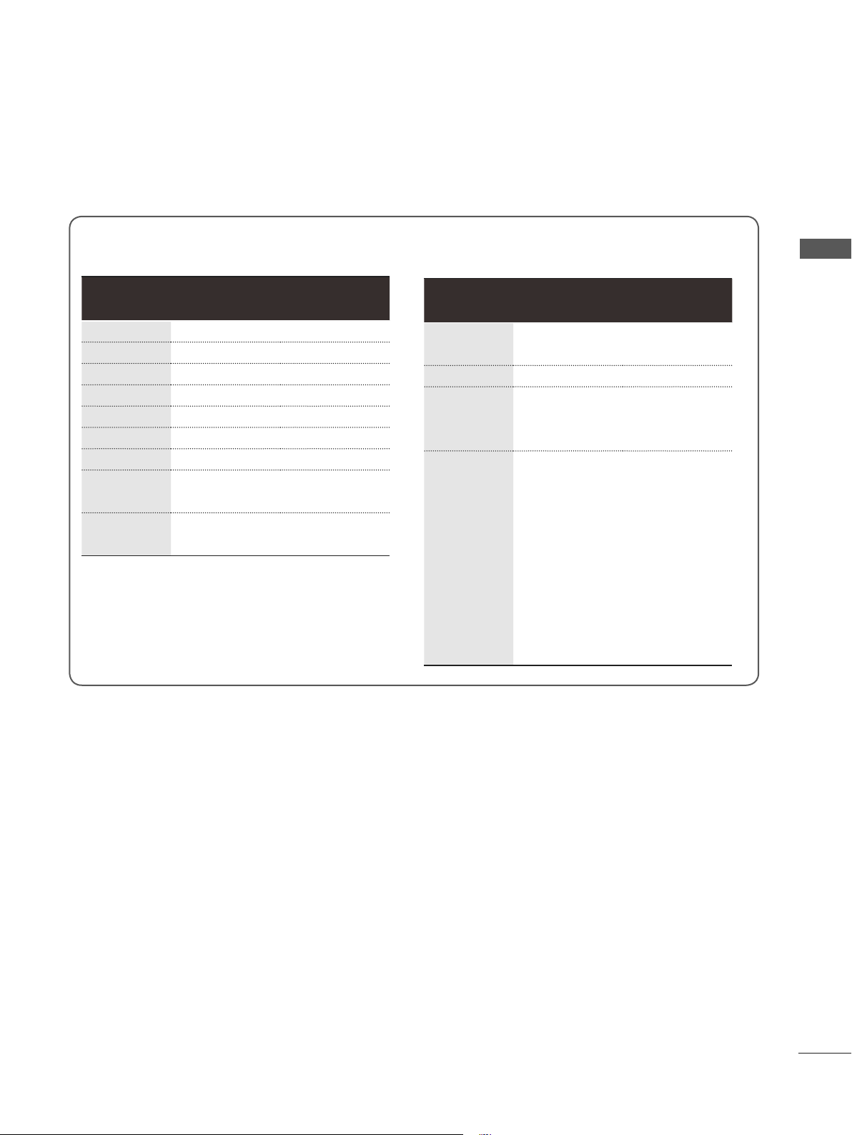
SUPPORTED DISPLAY RESOLUTION
RGB-PC, HDMI/DVI-PC mode
Resolution
720x400 31.468 70.08
640x480 31.469 59.94
800x600 37.879 60.31
1024x768 48.363 60.00
1280x768 47.78 59.87
1360x768 47.72 59.80
1280x1024 63.595 60.02
1920x1080
(RGB-PC)
1920x1080
(HDMI-PC)
Horizontal
Frequency
(kHz)
66.587 59.93
67.5 60.00
Vertical
Frequency (Hz)
HDMI/DVI-DTV mode
Resolution
720x480
720x576 31.25 50
1280x720
1920x1080
Horizontal
Frequency
(kHz)
31.469
31.5
37.5
44.96
45
33.72
33.75
28.125
26.97
27
33.716
33.75
56.25
67.43
67.5
Frequency (Hz)
EXTERNAL EQUIPMENT SETUP
Vertical
59.94
60
50
59.94
60
59.94
60
50
23.97
24
29.976
30.00
50
59.94
60
11

EXTERNAL EQUIPMENT SETUP
NOTE
► Avoid keeping a fixed image on the set’s screen
for prolonged periods of time. The fixed image
may become permanently imprinted on the
screen; use a screen saver when possible.
EXTERNAL EQUIPMENT SETUP
► There may be interference relating to resolution,
vertical pattern, contrast or brightness in PC
mode. Change the PC mode to another resolution
or change the refresh rate to another rate or
adjust the brightness and contrast on the menu
until the picture is clear. If the refresh rate of the
PC graphic card can not be changed, change the
PC graphic card or consult the manufacturer of
the PC graphic card.
► The synchronization input waveform for Horizontal
and Vertical frequencies are separate.
► We recommend using 1920x1080, 60 Hz
PC mode, this should provide the best picture
quality.
► Connect the signal cable from the monitor output
port of the PC to the RGB (PC) port of the TV or
the signal cable from the HDMI output port of the
PC to the HDMI IN (or HDMI/DVI IN) port on the
TV.
for the
► If you use too long an RGB-PC cable, there may be
► Connect the audio cable from the PC to the Audio
input on the TV. (Audio cables are not included with
the TV).
► If using a sound card, adjust PC sound as required.
► If the graphic card on the PC does not output ana-
logue and digital RGB simultaneously, connect only
one of either RGB or HDMI IN (or HDMI/DVI IN) to
display the PC output on the TV.
► If the graphic card on the PC does output analogue
and digital RGB simultaneously, set the TV to either
RGB or HDMI; (the other mode is set to Plug and
Play automatically by the TV.)
► DOS mode may not work depending on the video
card if you use an HDMI to DVI cable.
interference on the screen. We recommend using
under 5m of cable. This provides the best picture
quality.
12
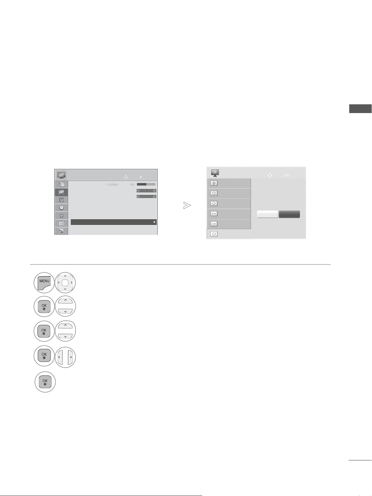
SCREEN SETUP FOR PC MODE
C
C
olou
olou
r 60
r 60
Screen Reset
Returns Position, Size and Phase to the factory default settings.
This function works in the following mode : RGB[PC].
PICTURE
• Tint 0
• Colour Temp. 0
• Advanced Control
• Picture Reset
• TruMotion : Off
• Screen
• Screen
• LED Local Dimming : On
Move
OK
RG
C
W
►
►
SCREEN
Resolution
Auto Config.
Position
Size
Phase
Reset
Move
To Set
Yes No
EXTERNAL EQUIPMENT SETUP
Prev.
1
2
3
4
Select PICTURE.
Select Screen.
Select Reset.
Select Yes.
5
Run Reset.
• Press the MENU/EXIT button to return to normal TV viewing.
• Press the BACK button to move to the previous menu screen.
13
EXTERNAL EQUIPMENT SETUP
C
C
olou
olou
r 60
r 60
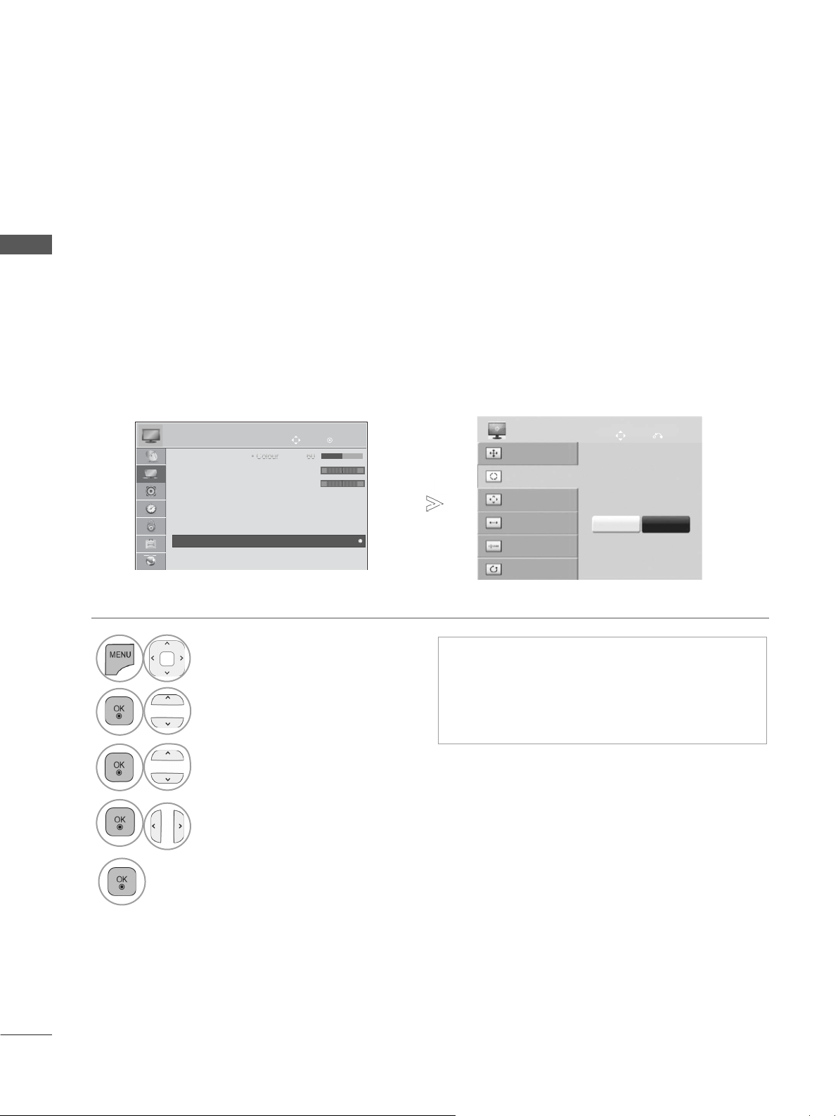
Auto Configure (RGB [PC] mode only)
Automatically adjusts the picture position and minimizes image instability. After adjustment, if the
EXTERNAL EQUIPMENT SETUP
image is still not correct, your TV is functioning properly but needs further adjustment.
Auto configure
This function is for automatic adjustment of the screen position, size, and phase The displayed image
will be unstable for a few seconds while the auto configuration is in progress.
PICTURE
• Tint 0
• Colour Temp. 0
• Advanced Control
• Picture Reset
• TruMotion : Off
• Screen
• Screen
• LED Local Dimming : On
Move
OK
RG
W
C
►
►
SCREEN
Resolution
Auto Config.
Position
Size
Phase
Reset
Move
Auto Config.
Yes No
Prev.
1
2
3
4
5
Select PICTURE.
Select Screen.
Select Auto Config..
Select Yes.
Run Auto Config..
• If the position of the image is still not correct,
try Auto adjustment again.
• If picture needs to be adjusted again after
Auto adjustment in RGB (PC), you can adjust
the Position, Size or Phase.
• Press the MENU/EXIT button to return to normal TV viewing.
• Press the BACK button to move to the previous menu screen.
14
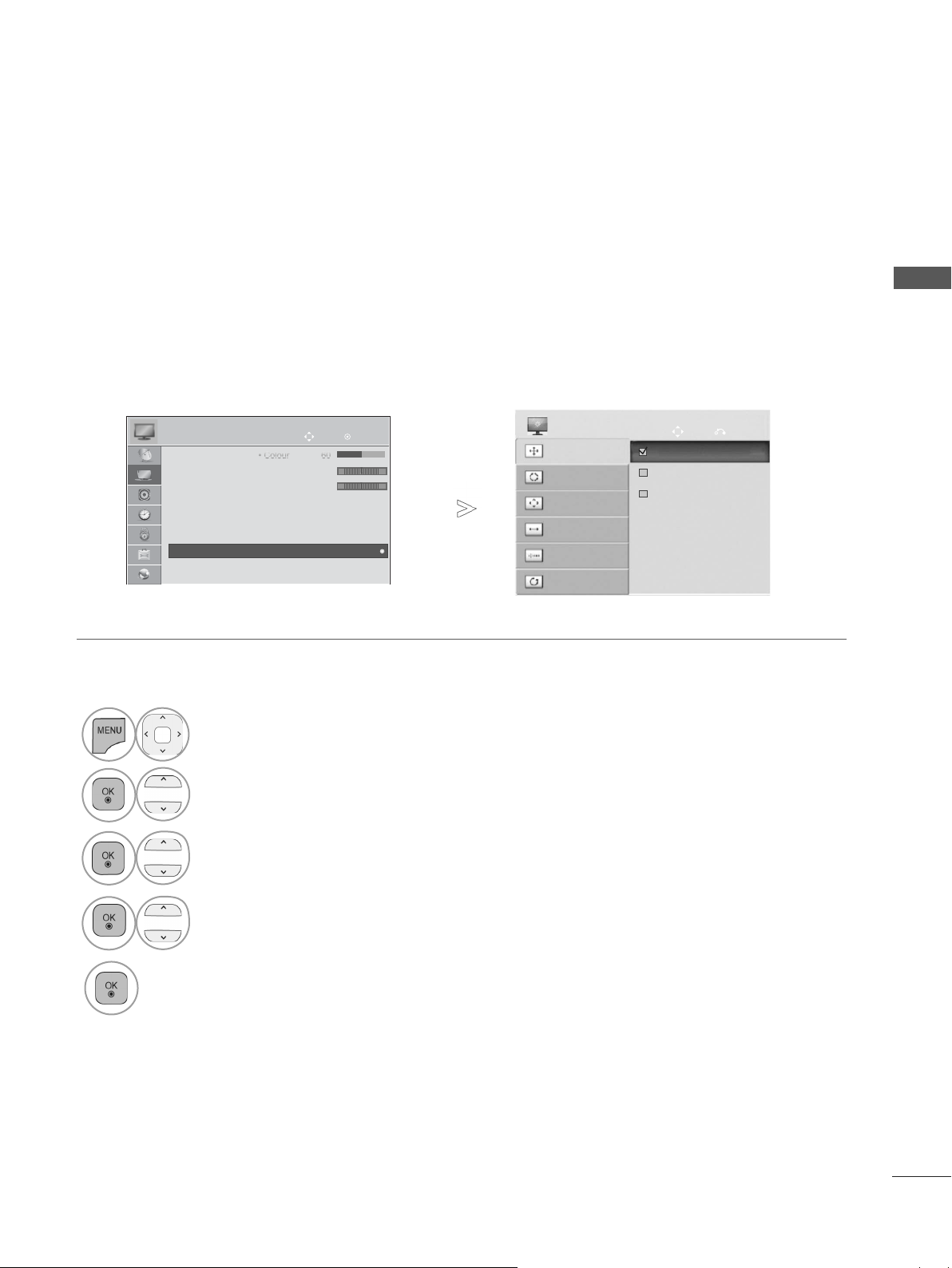
Selecting Resolution
C
C
olou
olou
r 60
r 60
To view a normal picture, match the resolution of RGB mode and selection of PC mode.
This function works in the following mode: RGB[PC]
PICTURE
• Tint 0
• Colour Temp. 0
• Advanced Control
• Picture Reset
• TruMotion : Off
• Screen
• Screen
• LED Local Dimming : On
Move
OK
RG
C
W
►
SCREEN
Resolution
Auto Config.
Position
►
Size
Phase
Reset
Move
1024 x 768
1280 x 768
1360 x 768
EXTERNAL EQUIPMENT SETUP
Prev.
1
2
3
4
Select PICTURE.
Select Screen.
Select Resolution.
Select the desired resolution.
5
• Press the MENU/EXIT button to return to normal TV viewing.
• Press the BACK button to move to the previous menu screen.
15
EXTERNAL EQUIPMENT SETUP
C
C
olou
olou
r 60
r 60
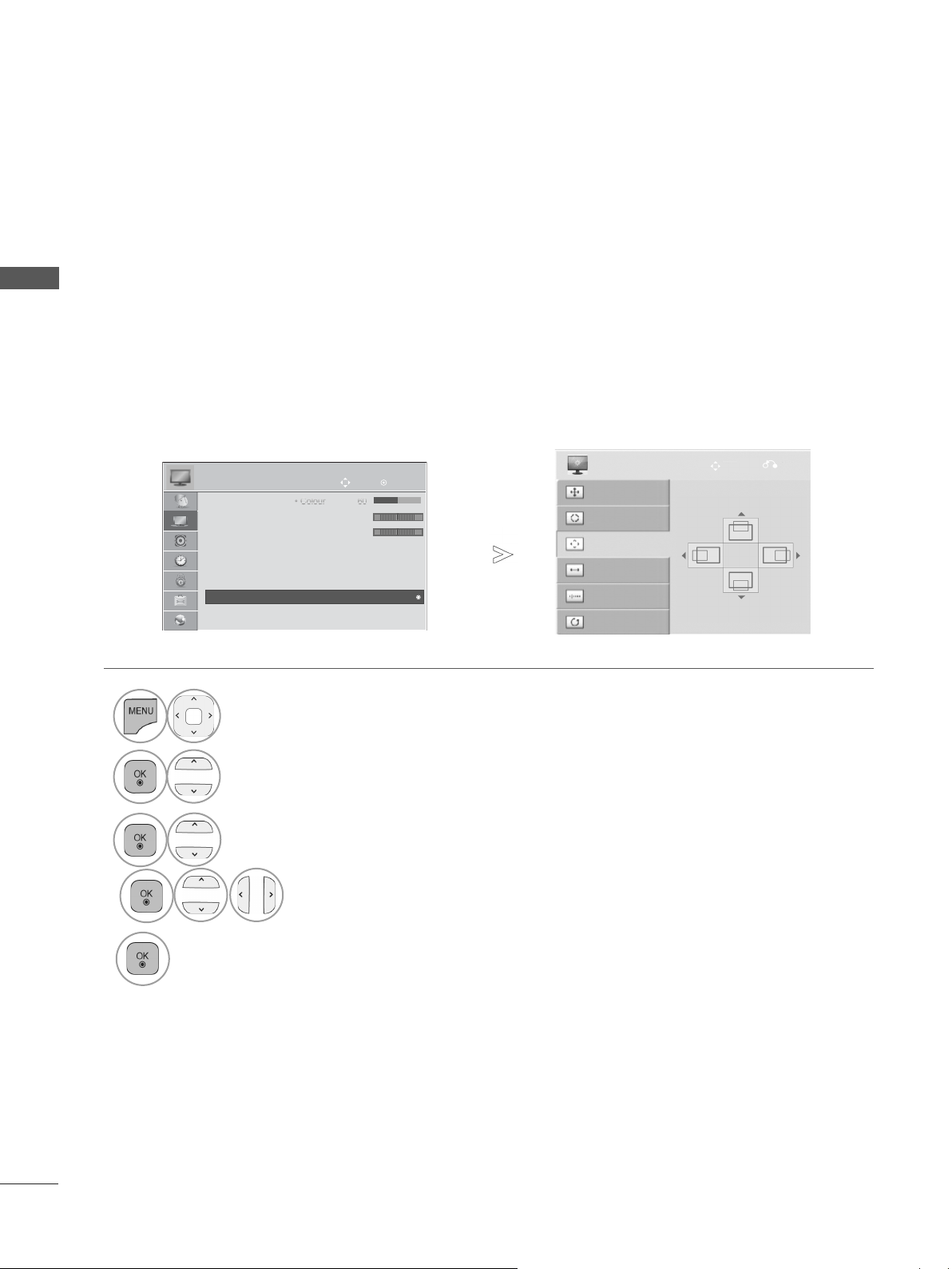
Adjustment for screen Position, Size, Phase
If the picture is not clear after auto adjustment and especially if characters are still trembling, adjust
EXTERNAL EQUIPMENT SETUP
the picture position manually.
This function works in the following mode : RGB[PC].
1
2
3
4
PICTURE
• Tint 0
• Colour Temp. 0
• Advanced Control
• Picture Reset
• TruMotion : Off
• Screen
• Screen
• LED Local Dimming : On
Move
OK
RG
W
Select PICTURE.
Select Screen.
Select Position, Size or Phase.
Make appropriate adjustments.
SCREEN
Resolution
C
►
►
Auto Config.
Position
Size
Phase
Reset
Move
Prev.
5
16
• Press the MENU/EXIT button to return to normal TV viewing.
• Press the BACK button to move to the previous menu screen.
 Loading...