

LG 42LC41, 42PC52, 42LC42 User Manual

LCD TV
PLASMA TV
OWNER’S MANUAL
LCD TV MODELS
26LC4
*
32LC4
*
37LC4
*
42LC4
*
26LC3
*
PLASMA TV MODELS
42PC5
*
42PC5RV
*
50PC5
*
Please read this manual carefully before operating your set.
Retain it for future reference.
Record model number and serial number of the set.
See the label attached on the back cover and quote
this information to your dealer when you require service.
26LC5*
32LC5*
37LC5*
42LC5*
ENGLISH

1
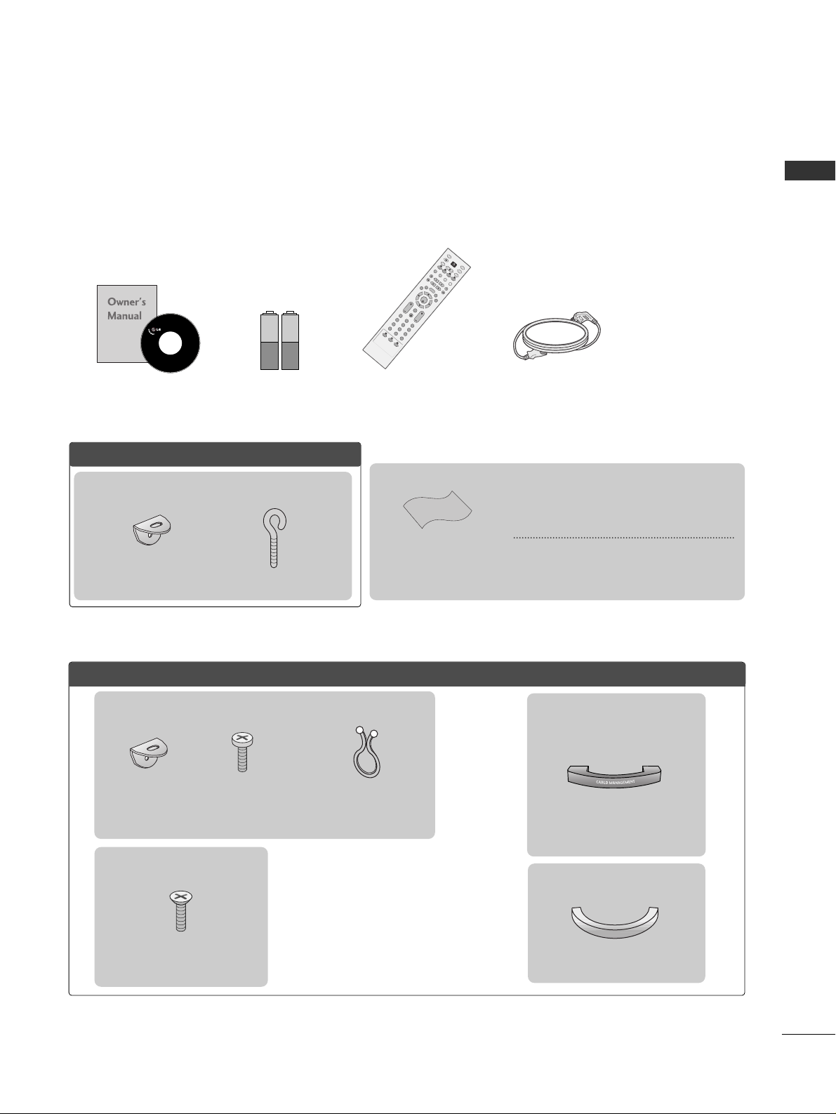
ACCESSORIES
Ensure that the following accessories are included with your TV. If an accessory is missing, please contact the
dealer where you purchased the product.
Owner’s Manual Batteries
OK
IN
P
U
T
T
V
T
V
P
IP
P
R
P
I
P
P
R
+
P
I
P
I
N
P
U
T
D
V
D
AR
C
EXIT
V
O
L
T
IM
E
R
E
V
E
A
L
IN
D
E
X
Q
.V
IE
W
P
R
SLEEP
LIST
I/II
M
E
N
U
P
IP
SI
Z
E
P
O
S
T
I
O
N
V
C
R
P
O
W
E
R
123
456
789
*
FAV
?
0
T
E
X
T
I
N
P
U
T
M
UT
E
Remote Control Power Cord
PPllaassmmaa TTVV mmooddeellss
2-Wall brackets
2-eye-bolts
ACCESSORIES
Polishing Cloth
Polish the screen with the cloth
This feature is not available
for all models.
*Slightly wipe stained spot on the exterior only
with the cleansing cloths for the product exterior if there is stain or fingerprint on surface of the
exterior.
Do not wipe roughly when removing stain.
Please be cautious of that excessive power may
cause scratch or discoloration.
This feature is not available for all models.
2- TV Brackets
2- Wall Brackets
2-bolts
Twister Holder
Arrange the wires with
the twister holder.
LLCCDD TTVV mmooddeellss
4-bolts for stand assembly
Refer to p. 8
22 66 ””,, 3322””,, 3377”” oo nnllyy
Cable
Management
2266LLCC44**,, 3322LLCC44**,, 3377LLCC44**,,
4422LLCC44**,, 2266LLCC55**,, 3322LLCC55**,,
3377LLCC55**,, 4422LLCC55
** oonnllyy
Cable Management
2266LLCC33RR**oonnllyy
This feature is not available for all models.
2
CONTENTS
PREPARATION
Front Panel Controls....................................................... 4
Back Panel Information .................................................. 6
Stand Installation............................................................. 8
Attaching the TV to a Wall.............................................9
Back Cover for Wire Arrangement............................ 10
Desktop Pedestal Installation..................................... 12
Wall Mount: Horizontal installation.......................... 13
Antenna Connection .................................................... 14
PICTURE CONTROL
Picture Size (Aspect Ratio)Control...........................46
Preset Picture Settings
- Picture Mode-Preset .............................................48
- Auto Colour Tone Control(Warm/Medium/Cool)
..49
Manual Picture Adjustment
- Picture Mode-User Option .................................50
- Colour Tone - User Option .................................51
-
Picture Improvement Technology
.....................52
Demo...................................................................53
Advanced - Cinema........................................................54
Advanced - Black(Darkness) Level.............................55
Picture Reset....................................................................56
Image Sticking Minimization(ISM) Method ............57
Low-Power Picture Mode..............................................58
SOUND & LANGUAGE CONTROL
Auto Volume Leveler......................................................59
Preset Sound Settings - Sound Mode......................60
Sound Setting Adjustment - User Mode .................61
Balance..............................................................................62
TV Speakers On/Off Setup .........................................63
I/II
- Stereo/Dual Reception.........................................64
- NICAM Reception..................................................65
- Speaker Sound Output Selection .....................65
On-Screen Menu Language /Country Selection
...... 66
EXTERNAL EQUIPMENT SETUP
HD Receiver Setup .........................................................15
DVD Setup....................................................................... 18
VCR Setup....................................................................... 21
Other A/V Source Setup ............................................ 24
External Stereo............................................................... 25
PC Setup...........................................................................26
- Screen Setup for PC Mode .................................28
WATCHING TV /PROGRAMME CONTROL
Remote Control Key Functions...................................32
Turning on the TV......................................................... 34
Programme Selection ................................................... 34
Volume Adjustment........................................................34
On Screen Menu Selection and Adjustment ..........35
Auto Programme Tuning.............................................. 36
Manual Programme Tuning ......................................... 37
Fine Tuning .......................................................................38
Assigning a Station Name............................................39
Programme Edit ............................................................. 40
Favourite Programme.................................................... 41
Calling the Programme Table ..................................... 42
Key lock ........................................................................... 43
................................................................... 44
PREPARATION
PICTURE CONTROL
WATCHING TV / PROGRAMME CONTROL
AACCCCEESSSSOORRIIEESS
......................................................1
CONTENTS

3
CONTENTS
APPENDIX
Troubleshooting..............................................................74
Maintenance ...................................................................76
Product Specifications..................................................77
Programming the Remote Control .......................... 79
TIME SETTING
Clock Setup......................................................................67
Auto On/Off Timer Setting .........................................68
Sleep Timer Setting .......................................................69
Auto Shut-off Setting ....................................................70
TELETEXT
Switch On/Off.................................................................71
SIMPLE Text .....................................................................71
TOP Text...........................................................................72
FASTEXT...........................................................................72
Special Teletext Functions............................................73
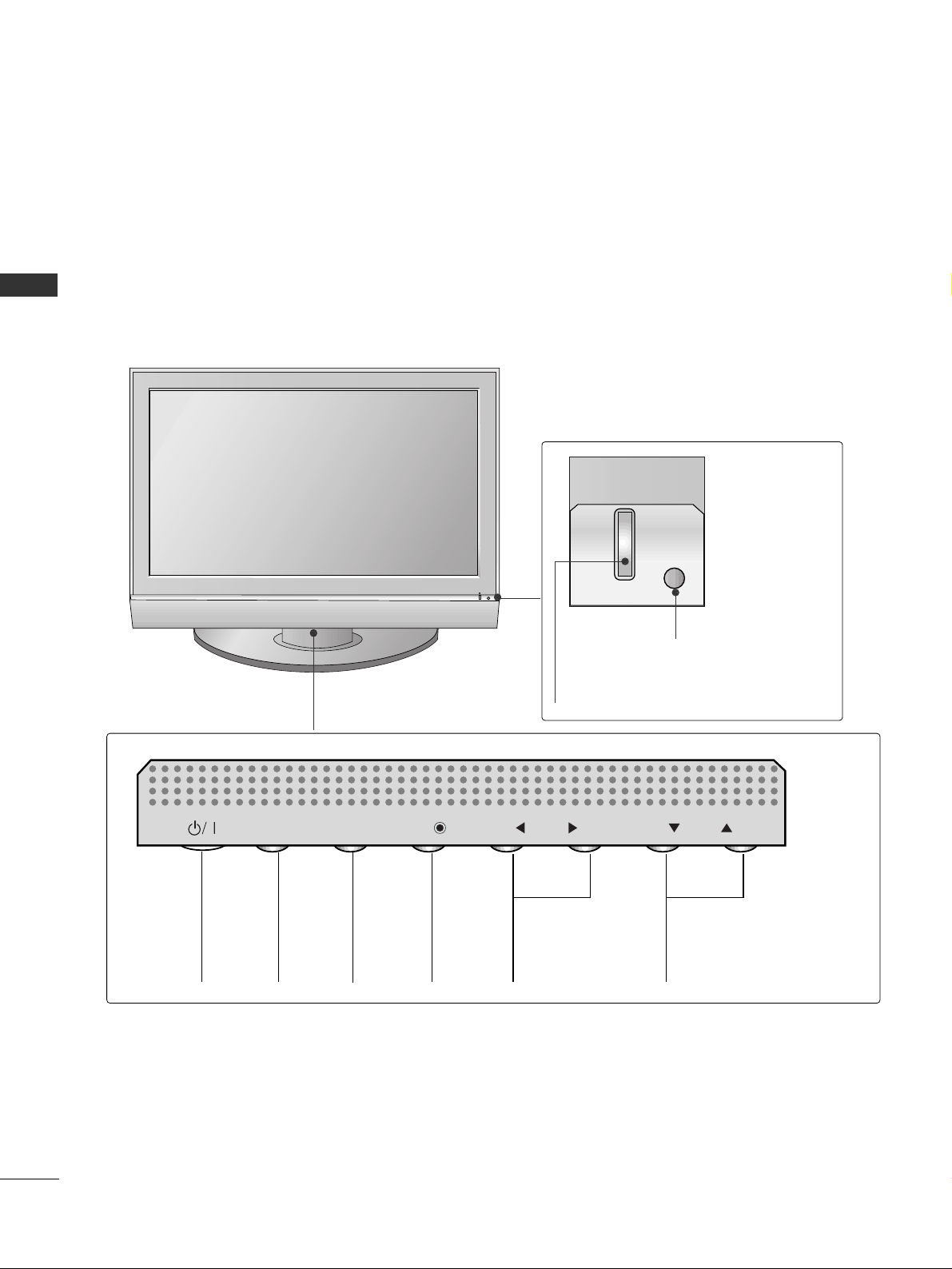
4
PREPARATION
FRONT PANEL CONTROLS
PREPARATION
■
This is a simplified representation of the front panel. Here shown may be somewhat different from your TV.
■
If your product has a protection film attached, remove the film and then wipe the product with a polishing
cloth.
Plasma TV Models
PROGRAMME
Buttons
VOLUME
Buttons
MENU
Button
OK
Button
INPUT
Button
POWER
Button
PR
VOL
OK
MENU
INPUT
Power/Standby Indicator
• illuminates red in standby mode.
• illuminates green when the set is switched on.
Remote Control Sensor
5
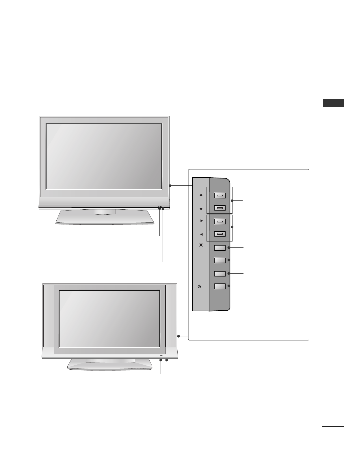
PREPARATION
LCD TV Models
R
Remote Control Sensor
Power/Standby Indicator
• illuminates red in standby mode.
• illuminates green when the set is switched on.
PROGRAMME Buttons
VOLUME Buttons
OK Button
MENU Button
INPUT Button
POWER Button
26 LC4*, 32LC4*, 37LC4*, 42LC4*, 26LC5*, 32LC5*,
37 LC 5*, 42LC5
*
R
Remote Control Sensor
Power/Standby Indicator
• illuminates red in standby mode.
• illuminates green when the set is switched on.
26LC3R
*
PR
VOL
OK
MENU
INPUT
/I
6
PREPARATION
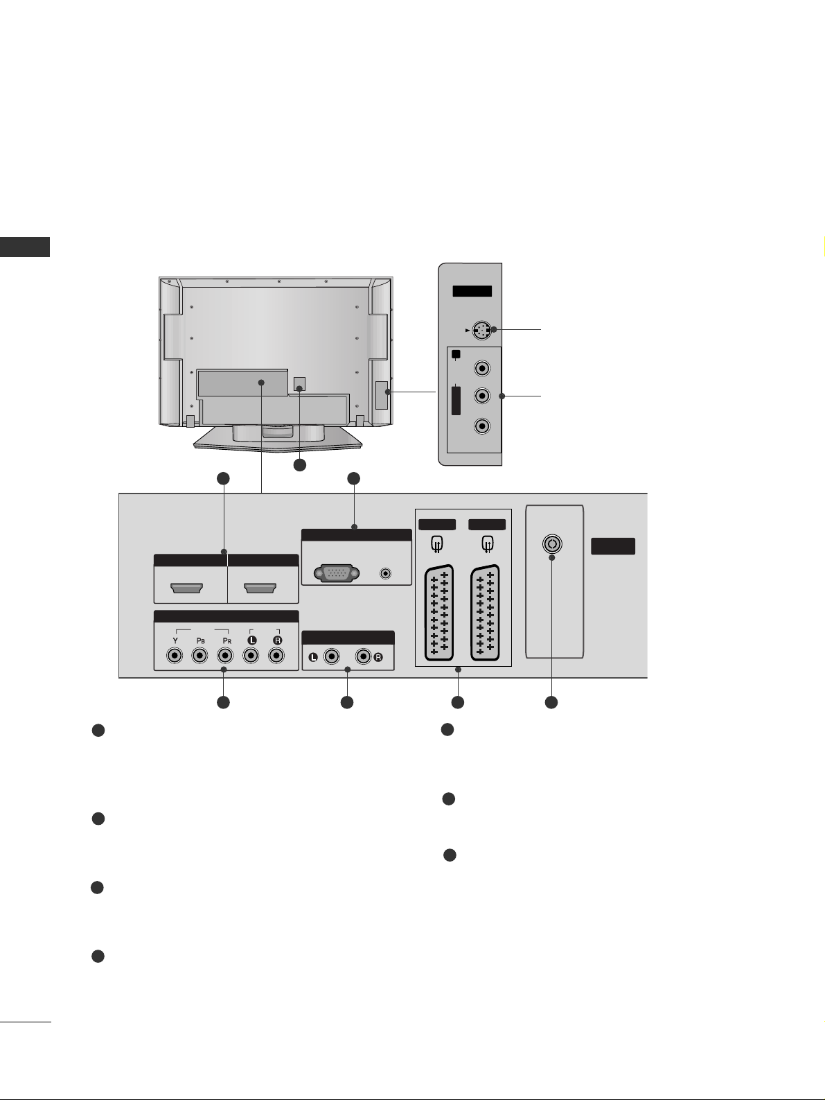
BACK PANEL INFORMATION
PREPARATION
■
This is a simplified representation of the back panel. Here shown may be somewhat different from your TV.
Plasma TV Models
HDMI Input
Connect a HDMI signal to HDMI IN.
Or DVI(VIDEO)signal to HDMI/DVI port with DVI
to HDMI cable.
RGB/Audio Input
Connect the monitor output from a PCto the
appropriate input port.
Component Input
Connect a component video/audio device to
these jacks.
Variable Audio Output
Connect an external amplifier or add a subwoofer
to your surround sound system.
Euro Scart Socket (AV1/AV2)
Connect scart socket input or output from an
external device to these jacks.
Antenna Input
Connect over-the-air signals to this jack.
Power Cord Socket
This TV operates on an AC power. The voltage is
indicated on the Specifications page. Never
attempt to operate the TV on DC power.
1
2
3
4
5
6
7
AV IN 3
L/MONO
R
AUDIO
VIDEO
S-VIDEO
V 1
ARIABLE
AUDIO OUT
VIDEO
COMPONENT
AV IN 3
L/ MONO
R
AUDIO
VIDEO
S-VIDEO
21
43 5 6
7
S-Video Input
Connect S-Video out from an
S-VIDEO device.
Audio/Video Input
Connect audio/video output
from an external device to
these jacks.
AV IN 3V IN 3
L/L/MONOMONO
R
AUDIOAUDIO
VIDEOVIDEO
S-VIDEOS-VIDEO
RGB IN
RGB
(PC)
VARIABLE
AUDIO OUT
HDMI/DVI IN HDMI IN
1 2
COMPONENT
VIDEO
IN
AUDIO
AUDIO
(RGB/DVI)
AV 1
AV 2
ANTENNA
IN
7
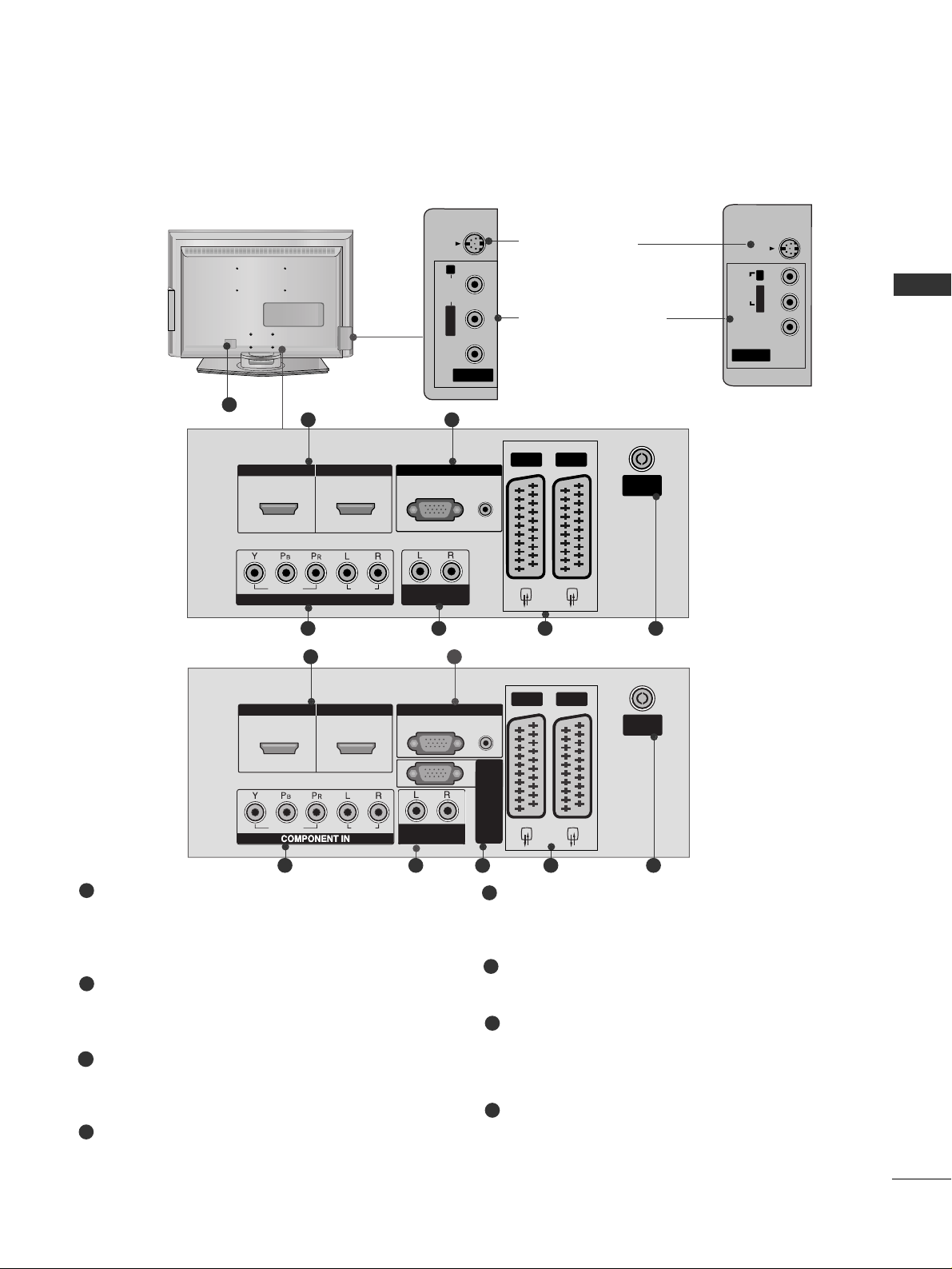
PREPARATION
HDMI Input
Connect a HDMI signal to HDMI IN.
Or DVI(VIDEO)signal to HDMI/DVI port with DVI
to HDMI cable.
RGB/Audio Input
Connect the monitor output from a PC to the
appropriate input port.
Component Input
Connect a component video/audio device to
these jacks.
Variable Audio Output
Connect an external amplifier or add a subwoofer
to your surround sound system.
Euro Scart Socket (AV1/AV2)
Connect scart socket input or output from an
external device to these jacks.
Antenna Input
Connect over-the-air signals to this jack.
Power Cord Socket
This TV operates on an AC power. The voltage is
indicated on the Specifications page. Never
attempt to operate the TV on DC power.
RS-232C Input
(CONTROL&SERVICE)Port
Connect the serial port of the control devices
to the RS-232C jack.
1
2
3
4
5
6
7
LCD TV Models
AV IN 3
L/MONO
R
AUDIO
VIDEO
S-VIDEO
VARIABLE
AUDIO OUT
RGB IN
O
O
AV 1
AV 2
ANTENNA
IN
HDMI/DVI IN
HDMI IN
21
43 5 6
7
V IN 3
MONO
AUDIO
VIDEO
S-VIDEO
8
AV IN 3
L/ MONO
R
AUDIO
VIDEO
S-VIDEO
1 2
VARIABLEARIABLE
AUDIO OUTAUDIO OUT
RGB
(PC)
RGB INRGB IN
COMPONENT INCOMPONENT IN
AUDIOAUDIO
VIDEOVIDEO
AV 1 AV 2
ANTENNAANTENNA
IN IN
AUDIO
(RGB/DVI)
HDMI/DVI INHDMI/DVI IN HDMI INHDMI IN
21
43 5 6
26LC51C
32LC52C
26 LC4*, 32LC4*, 37LC4*,
42 LC 4*, 26LC5*, 32LC5*,
37 LC 5*, 42LC5
*
S-Video Input
Connect S-Video out
from an S-VIDEO device.
Audio/Video Input
Connect audio/video
output from an external
device to these jacks.
AV IN 3
VIDEOVIDEO
S-VIDEOS-VIDEO
L/MONOMONO
R
AUDIOAUDIO
26LC3R
*
8
S-VIDEO
R
AUDIO
L/MONO
VIDEO
AV IN 3
HDMI/DVI IN
HDMI IN
1 2
VIDE
AUDI
AV 1
RGB IN
RGB
AUDIO
(PC)
(RGB/DVI)
VARIABLE
AUDIO OUT
RS-232C IN
(CONTROL & SERVICE)
AV 2
ANTENNA
IN
8
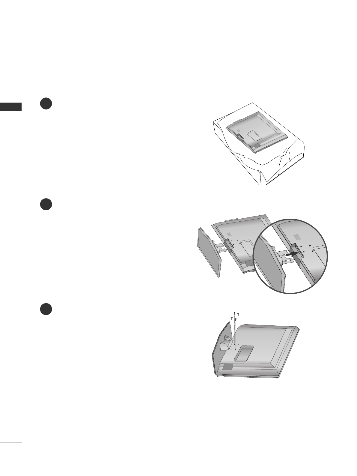
PREPARATION
STAND INSTALLATION (Only 26, 32, 37 inch LCD TV models)
PREPARATION
1
2
3
Carefully place the product screen side down on
a cushioned surface that will protect product and
screen from damage.
Assemble the product stand with the product as
shown.
Install the 4 bolts securely, in the back of the
product in the holes provided.
9
PREPARATION
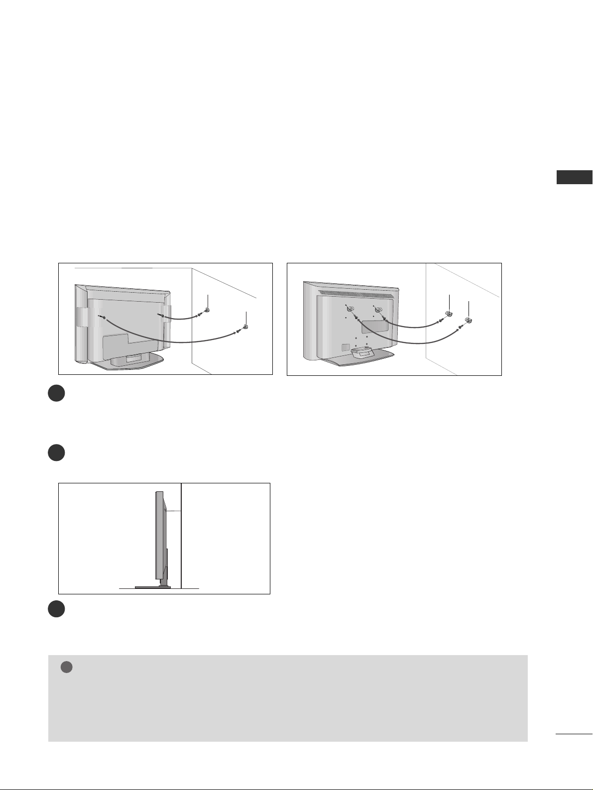
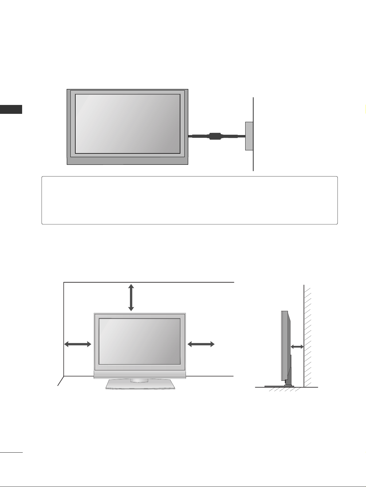
ATTACHING THE TV TO A WALL
Plasma TV models LCD TV models
2
1
■
This feature is not available for all models.
■
Set it up close to the wall so the product doesn’t fall over when it is pushed backwards.
■
The instructions shown below is a safer way to set up the product, which is to fix it on the wall so the
product doesn’t fall over when it is pulled in the forward direction. It will prevent the product from
falling for-ward and hurting people. It will also prevent the product from damage caused by fall. Please
make sure that children don’t climb on or hang from the product.
NOTE
!
GG
When moving the product to another place undo the ropes first.
GG
Use a product holder or a cabinet that is big and strong enough for the size and weight of the product.
GG
To use the product safely make sure that the height of the bracket that is mounted on the wall is same as
that of the product.
2
3
1
1
2
Use the eye-bolts or TV brackets/bolts to fix the product to the wall as shown in the picture.
(If your product has the bolts in the eye-bolts position before inserting the eye-bolts, loosen the bolts.)
* Insert the eye-bolts or TV brackets/bolts and tighten them securely in the upper holes.
Secure the wall brackets with the bolts (not provided as parts of the product, must purchase separately) on
the wall. Match the height of the bracket that is mounted on the wall.
3
Use a sturdy rope (not provided as parts of the product, must purchase separately) to tie the
product. It is safer to tie the rope so it becomes horizontal between the wall and the product.

10
PREPARATION
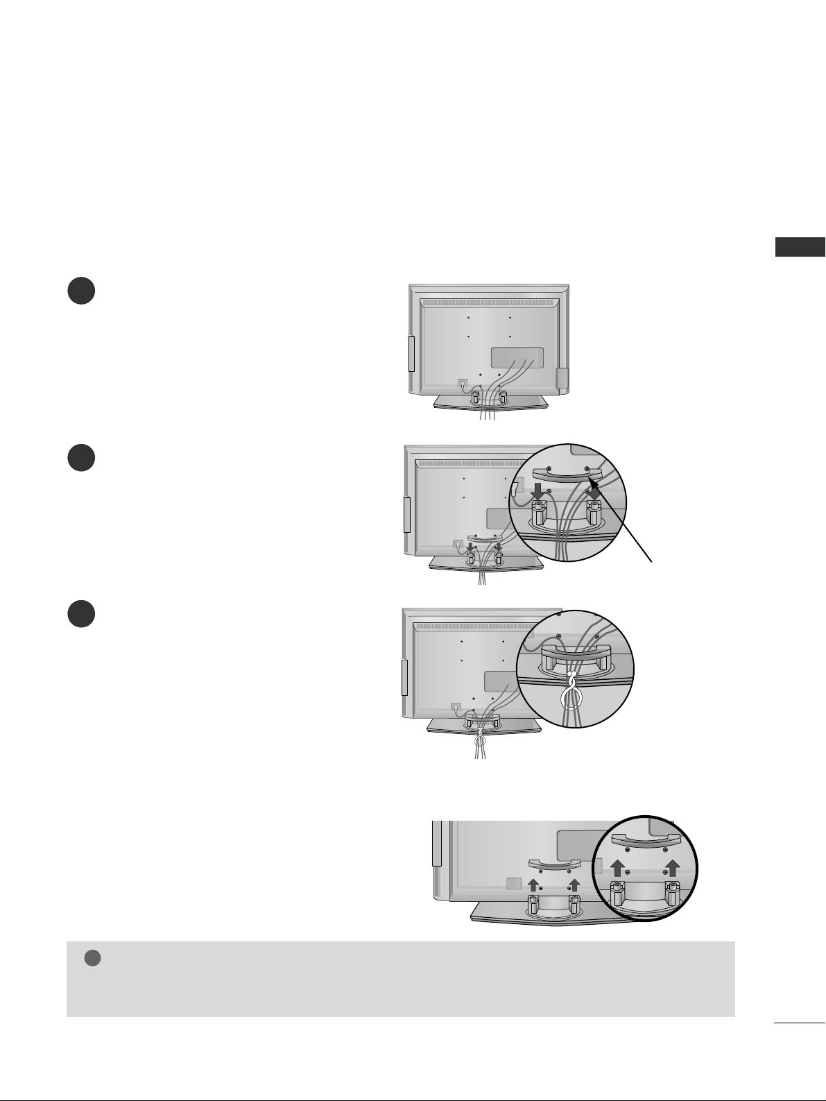
BACK COVER FOR WIRE ARRANGEMENT
PREPARATION
Plasma TV models
Connect the cables as necessary.
To connect an additional equipment, see the
EExxtteerrnnaall ee qquuiippmmee nntt SSee ttuupp
section.
Reinstall the
CCAABB LLEE MMAANNAA GGEE MMEENNTT
as shown.
2
1
3
CABLE MANAGEMENT
Hold the
CCAABB LLEE MMAANNAA GGEEMMEENNTT
with hands and push it as shown.
11
PREPARATION
LCD TV models
Connect the cables as necessary.
To connect an additional equipment, see the
EExxtteerrnnaall eeqquuiippmmeenntt SSee ttuupp
section.
1
Install the
CCAABB LLEE MMAANNAA GGEE MMEENNTT
as shown.
2
Bundle the cables using the supplied twister
holder.
(
This feature is not available for all models.)
3
Hold the
CCAA BBLL EE MMAA NNAAGGEEMMEENNTT
with both
hands and pull it upward.
NOTE
!
GG
Do not hold the
CCAABB LLEE MMAANNAA GGEEMMEENNTT
when moving the product.
- If the product is dropped, you may be injured or the product may be broken.
How to remove the cable management
CABLE MANAGEMENT
12
PREPARATION
■
The TV can be installed in various ways such as on a wall, or on a desktop etc.
■
The TV is designed to be mounted horizontally.
PREPARATION
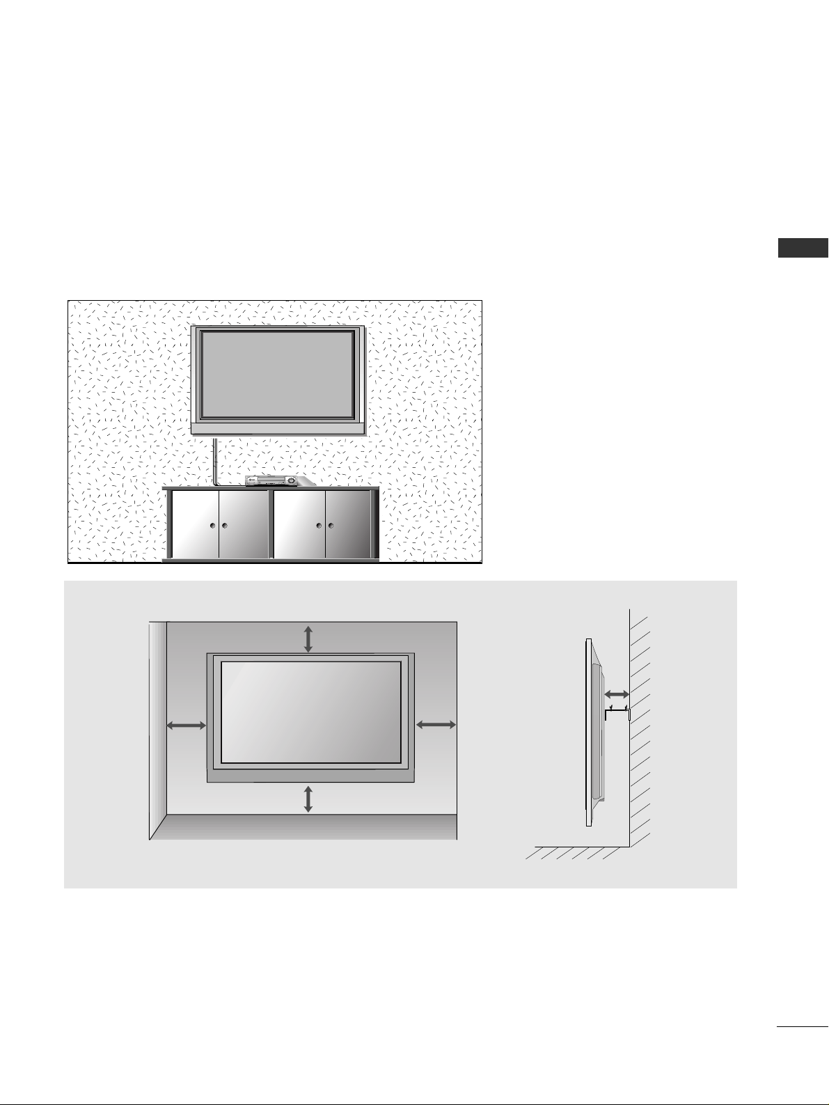
DESKTOP PEDESTAL INSTALLATION
For proper ventilation, allow a clearance of 4inches on each side from the wall.
4 inches
4 inches
4 inches
4 inches
Power Supply
Short-circuit Breaker
GROUNDING
Ensure that you connect the earth ground wire to prevent possible electric shock. If grounding methods
are not possible, have a qualified electrician install a separate circuit breaker.
Do not try to ground the unit by connecting it to telephone wires, lightening rods, or gas pipes.
13
PREPARATION
WALL MOUNT: HORIZONTAL INSTALLATION
For proper ventilation, allow a clearance of 4" on each side and from the wall. Detailed installation instructions are available from your dealer, see the optional Tilt Wall Mounting Bracket Installation and Setup Guide.
4 inches
4 inches
4 inches
4 inches
4 inches
14
PREPARATION
AV IN 3
L/MONO
R
AUDIO
VIDEO
S-VIDEO
AV IN 3
L/MONO
R
AUDIO
VIDEO
S-VIDEO
AV IN 3
L/ MONO
R
AUDIO
VIDEO
S-VIDEO
AV IN 3
L/ MONO
R
AUDIO
VIDEO
S-VIDEO
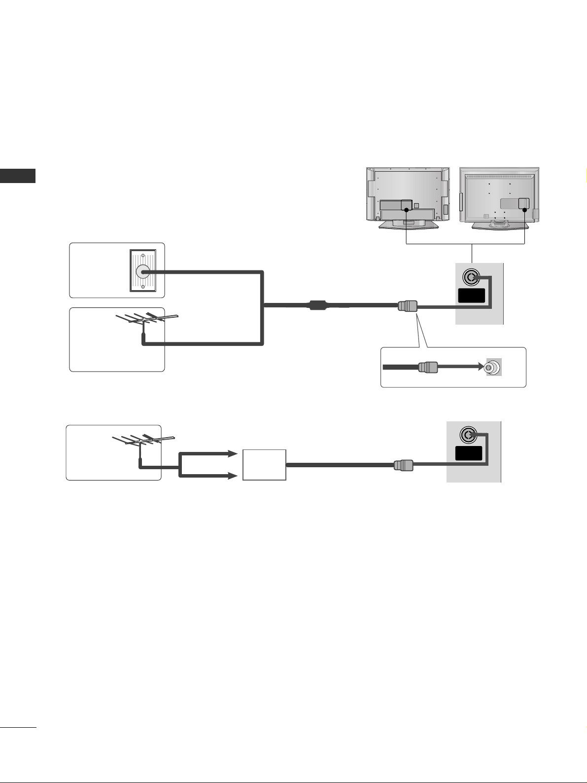
PREPARATION
ANTENNA CONNECTION
■
For optimum picture quality, adjust antenna direction.
■
An antenna cable and converter are not supplied.
Multi-family Dwellings/Apartments
(Connect to wall antenna socket)
Single-family Dwellings /Houses
(Connect to wall jack for outdoor antenna)
Outdoor
Antenna
Antenna
Wall
Antenna
Socket
RF Coaxial Wire (75 ohm)
UHF
Signal
Amplifier
VHF
■
In poor signal areas,to get better picture quality, install a signal amplifier to the antenna as shown above.
■
If signal needs to be split for two TVs,use an antenna signal splitter for connection.
■
To prevent the equipment damage, never plug in any power cords until you have finished connecting all equipment.
ANTENNA
IN
ANTENNA
IN
15
EXTERNAL EQUIPMENT SETUP
EXTERNAL EQUIPMENT SETUP
HD RECEIVER SETUP
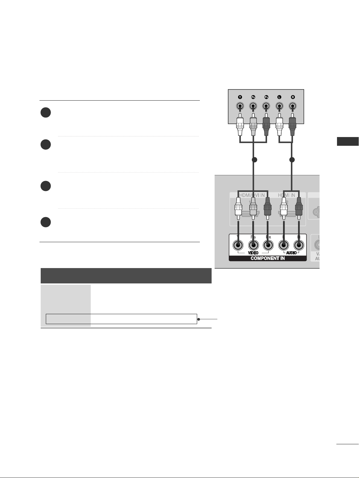
1
When connecting with a component cable
Connect the video outputs (Y, PB
, PR
)
of the digital set
top box to the
CCOOMMPPOONNEENNTT IINN VVIIDDEEOO
jacks on the
set.
Connect the audio output of the digital set-top box to
the
CCOOMMPPOONNEENNTT IINN AAUUDDIIOO
jacks on the set.
Turn on the digital set-top box.
(
Refer to the owner’s manual for the digital set-top box.
)
Select
Component input source with using the
II NNPP UUTT
button on the remote control.
2
3
4
1
1 2
■
To prevent the equipment damage, never plug in any power cords until you have finished connecting all equipment.
■
This part of EXTERNAL EQUIPMENT SETUP mainly use pictures for the LCD TV models.
Signal
480i/576i
480p/576p
720p/1080i
10 8 0 p
Component
Yes
Yes
Yes
No
HDMI1/2
No
Yes
Yes
Yes
(except VGA Models)
16
EXTERNAL EQUIPMENT SETUP
EXTERNAL EQUIPMENT SETUP
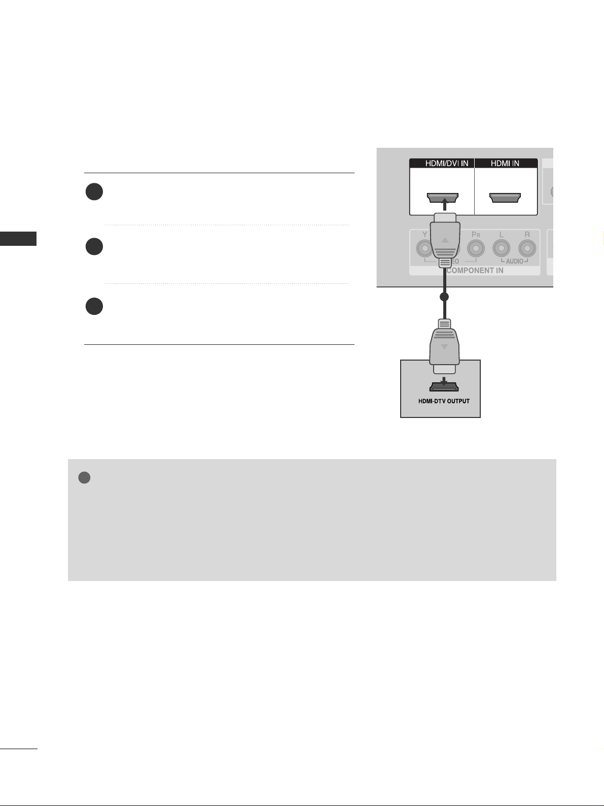
1
1 2
When connecting with a HDMI cable
Connect the HDMI output of the digital set-top box to
the
HHDDMMII// DDVVII II NN 11
or
HHDDMMII IINN 22
jack on the set.
Select
HDMI1 or HDMI2 input source with using the
II NNPP UUTT
button on the remote control.
Turn on the digital set-top box.
(
Refer to the owner’s manual for the digital set-top box.
)
2
3
1
GG
TV can receive the video and audio signal simultaneously with using a HDMI cable.
GG
If the digital set-top box supports Auto HDMI function, the output resolution of the source device will
be automatically set to 1280x720p.
GG
If the digital set-top box player does not support Auto HDMI, you need to set the output resolution
appropriately.
To get the best picture quality, adjust the output resolution of the source device to 1280x720p.
NOTE
!
1
17
EXTERNAL EQUIPMENT SETUP
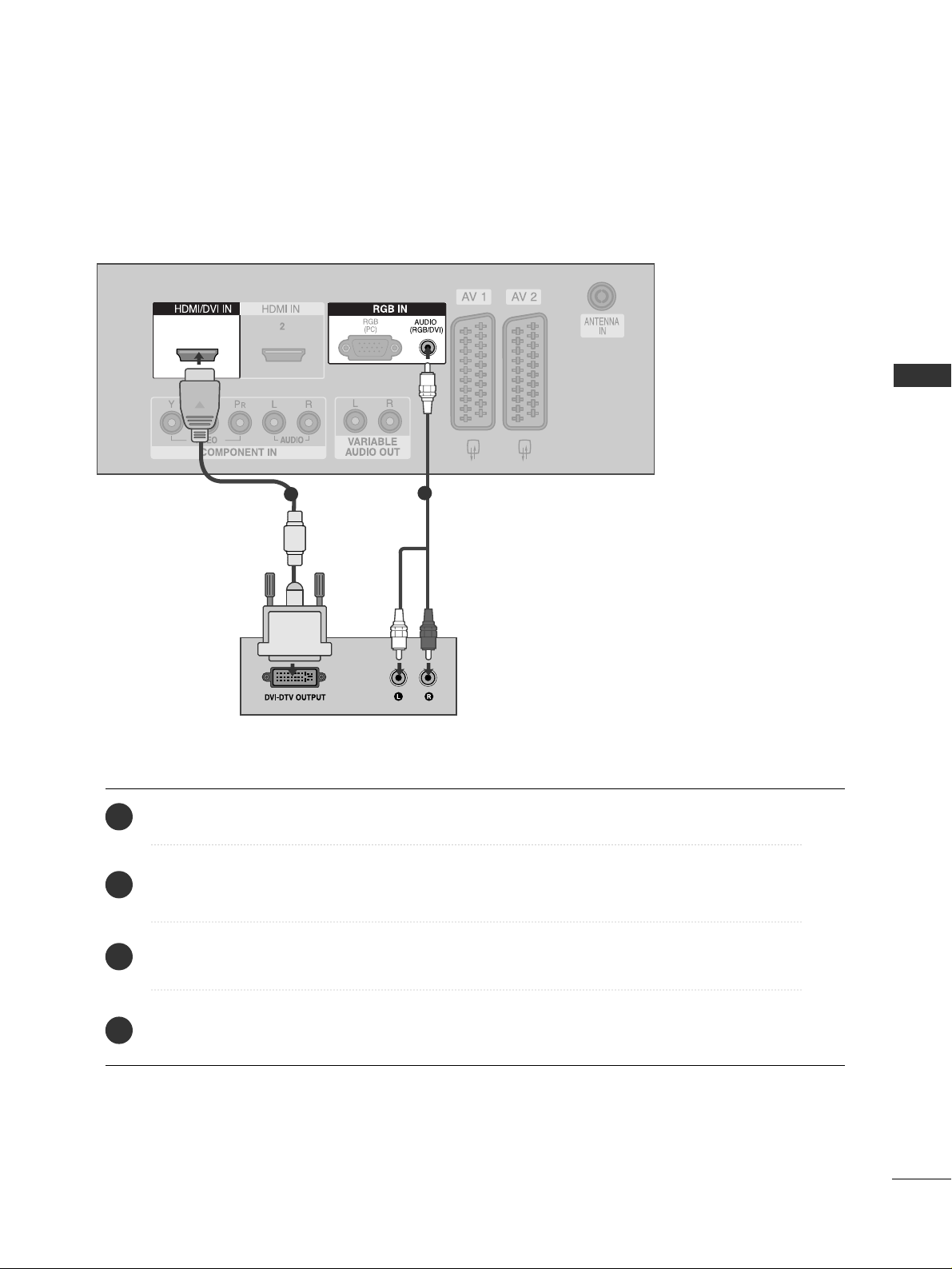
1
1
2
Connect the DVI output of the digital set-top box to the
HHDDMMII// DDVVII II NN 11
jack on the set.
Connect the audio output of the digital set-top box to the
AAUUDDII OO(( RRGGBB//DDVVII))
jack on the set.
Turn on the digital set-top box. (Refer to the owner’s manual for the digital set-top box.
)
Select
HDMI1 input source with using the
II NNPP UUTT
button on the remote control.
2
3
4
1
When connecting with a HDMI to DVI cable
18
EXTERNAL EQUIPMENT SETUP
DVD SETUP
EXTERNAL EQUIPMENT SETUP
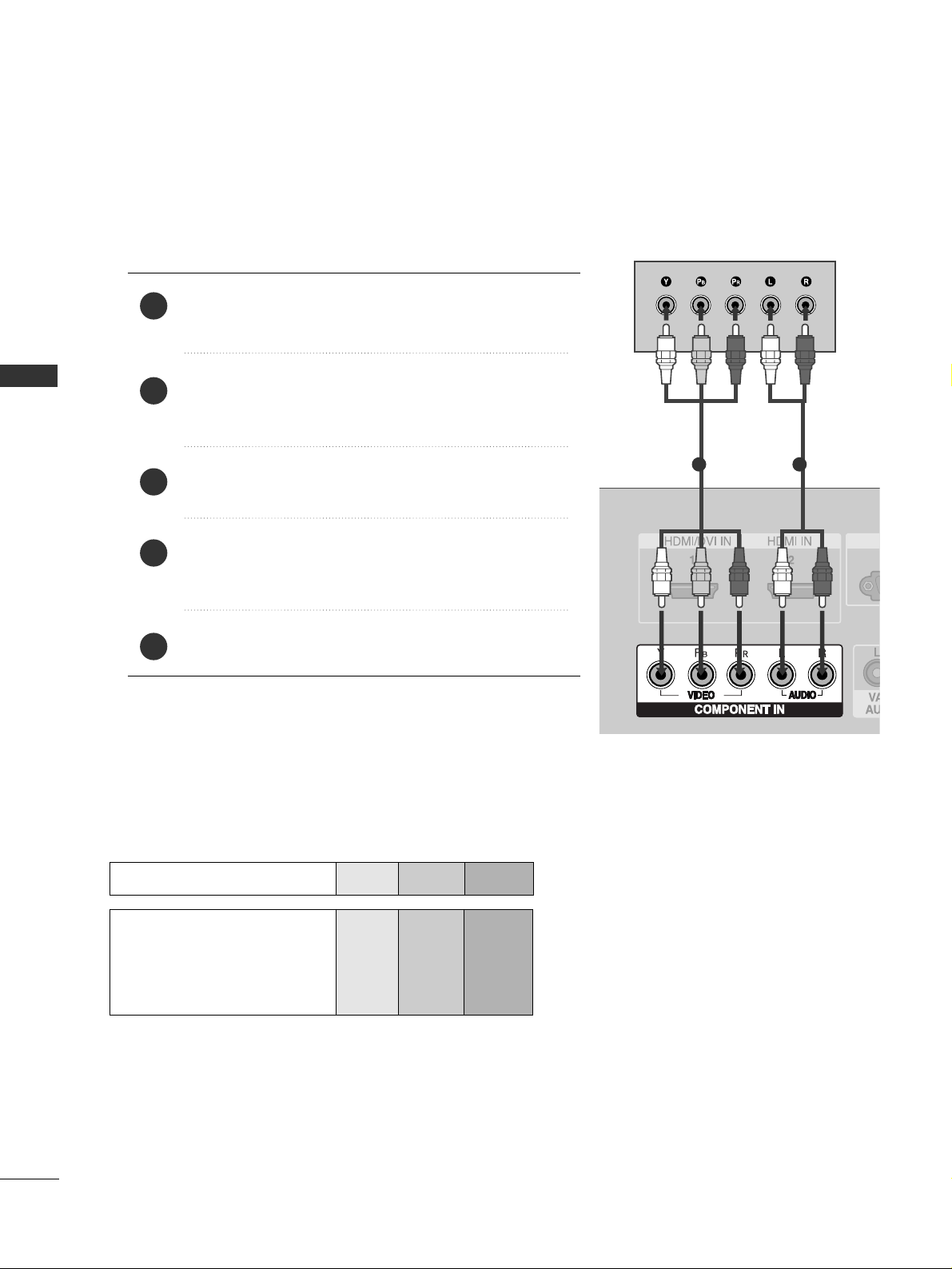
When connecting with a component cable
L/ MONO
R
AUDIO
VIDEO
S-VIDEO
Component Input ports
To get better picture quality, connect a DVD player to the component input ports as shown below.
Component ports on the TV
YPB PR
Video output ports
on DVD player
Y
Y
Y
Y
PB
B-Y
Cb
Pb
P
R
R-Y
Cr
Pr
Connect the video outputs (Y, PB
, PR
)
of the DVD to the
CCOOMMPPOONNEENNTT IINN VVIIDDEEOO
jacks on the set.
Connect the audio outputs of the DVD to the
CCOO MMPPOO--
NNEENNTT IINN AAUUDDIIOO
jacks on the set.
Turn on the DVD player, insert a DVD.
Select
Component input source with using the
II NNPP UUTT
button on the remote control.
Refer to the DVD player's manual for operating instructions.
2
3
4
5
1
1 2
19
EXTERNAL EQUIPMENT SETUP
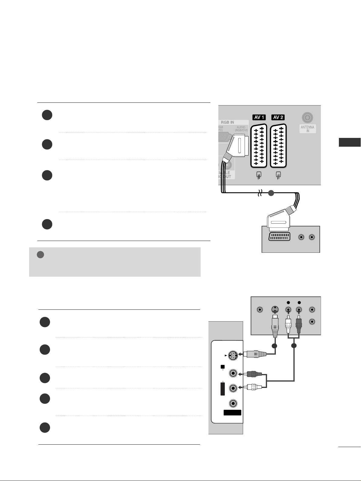
When connecting with a Euro Scart
Connect the Euro scart socket of the DVD to the
AAVV 11
Euro
scart socket on the set.
Turn on the DVD player, insert a DVD.
Select
AV 1 input source with using the
II NNPP UUTT
button on
the remote control.
If connected to
AV 2 Euro scart socket, select AV 2 input
source.
Refer to the DVD player's manual for operating instructions.
2
3
4
1
AV IN 3
L/ MONO
R
AUDIO
VIDEO
S-VIDEO
12
12
(R) AUDIO (L)
AUDIO/
VIDEO
1
NOTE
!
GG
Please use the shield scart cable.
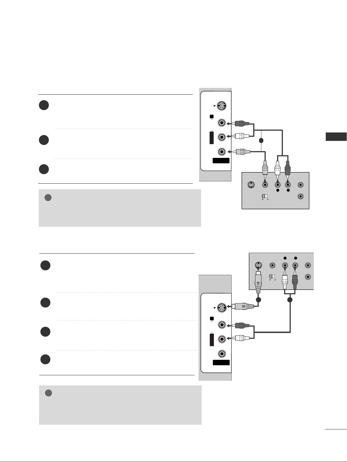
When connecting with an S-Video cable
AV IN 3
L/MONOMONO
R
AUDIOAUDIO
VIDEOVIDEO
S-VIDEO
L R
S-VIDEOVIDEO
OUTPUT
SWITCH
ANT IN
ANT OUT
Connect the S-VIDEO output of the DVD to the
SS--
VVIIDDEEOO
input on the set.
Connect the audio outputs of the DVD to the
AAUUDDIIOO
input jacks on the set.
Turn on the DVD player, insert a DVD.
Select
AV 3 input source with using the
II NNPP UUTT
but-
ton on the remote control.
Refer to the DVD player's manual for operating
instructions.
2
3
4
5
1
1
2
20
EXTERNAL EQUIPMENT SETUP
EXTERNAL EQUIPMENT SETUP
AV IN 3
L/ MONO
R
AUDIO
VIDEO
S-VIDEO
1 2
1 2
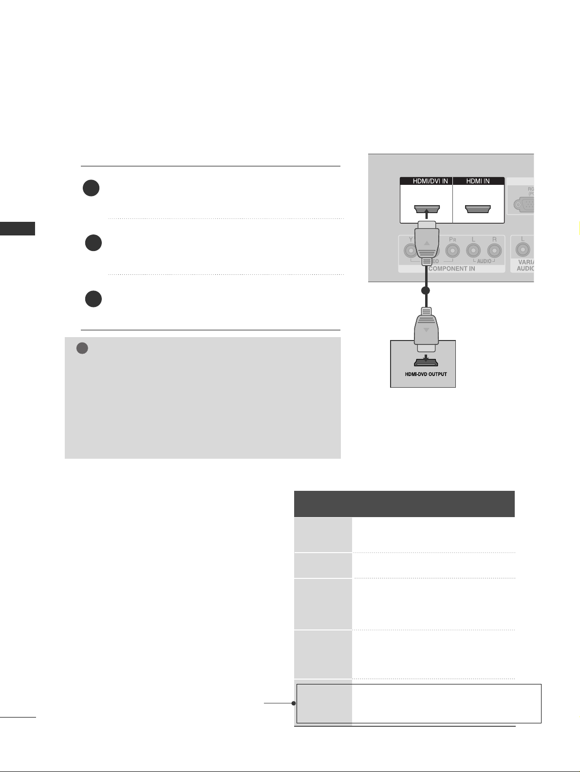
When connecting HDMI cable
Connect the HDMI output of the DVD to the
HHDDMMII// DDVVII II NN 11
or
HHDDMMII IINN 22
jack on the set.
Select
HDMI1 or HDMI2 input source with using
the
II NNPP UUTT
button on the remote control.
Refer to the DVD player's manual for operating
instructions.
1
GG
TV can receive the video and audio signal simultaneously
with using a HDMI cable.
GG
If the DVD supports Auto HDMI function, the output resolution of the source device will be automatically set to
1280x720p.
GG
If the DVD player does not support Auto HDMI, you need to
set the DVD output resolution appropriately.
To get the best picture quality, adjust the output resolution
of the source device to 1280x720p.
NOTE
!
1
2
3
Resolution
720x480
720x576
1280x720
1920x1080i
1920x1080p
Supported Display Resolution (HDMI-DTV mode)
Horizontal Vertical
Frequency(KHz) Frequency(Hz)
31.47 59.94
31.50 60.00
31.25 50.00
44.96 59.94
45.00 60.00
37.50 50.00
33.72 59.94
33.75 60.00
28.125 50.00
67. 432 59.94
67. 5 60
56.25 50
(except VGA Models)
21
EXTERNAL EQUIPMENT SETUP
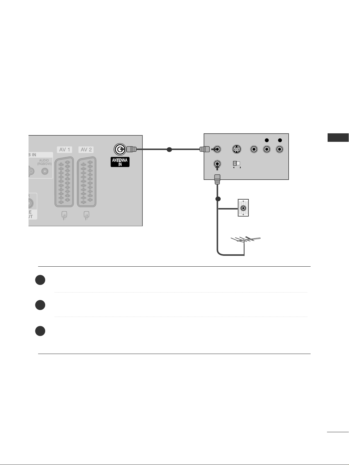
VCR SETUP
When connecting with an antenna
■
To avoid picture noise (interference), leave an adequate distance between the VCR and TV.
■
Typically a frozen still picture from a VCR. If the 4:3 picture format is used; the fixed images on the sides of
the screen may remain visible on the screen.
OUTPUT
SWITCH
ANT IN
R
S-VIDEO VIDEO
ANT OUT
L
Wall Jack
Antenna
Connect the
AANNTT OO UU TT
socket of the VCR to the
AANNTTEE NNNNAA IINN
socket on the set.
Connect the antenna cable to the
AANNTT IINN
socket of the VCR.
Press the
PPLL AAYY
button on the VCR and match the appropriate programme between the TV and VCR for
viewing.
1
2
2
3
1
22
EXTERNAL EQUIPMENT SETUP
EXTERNAL EQUIPMENT SETUP
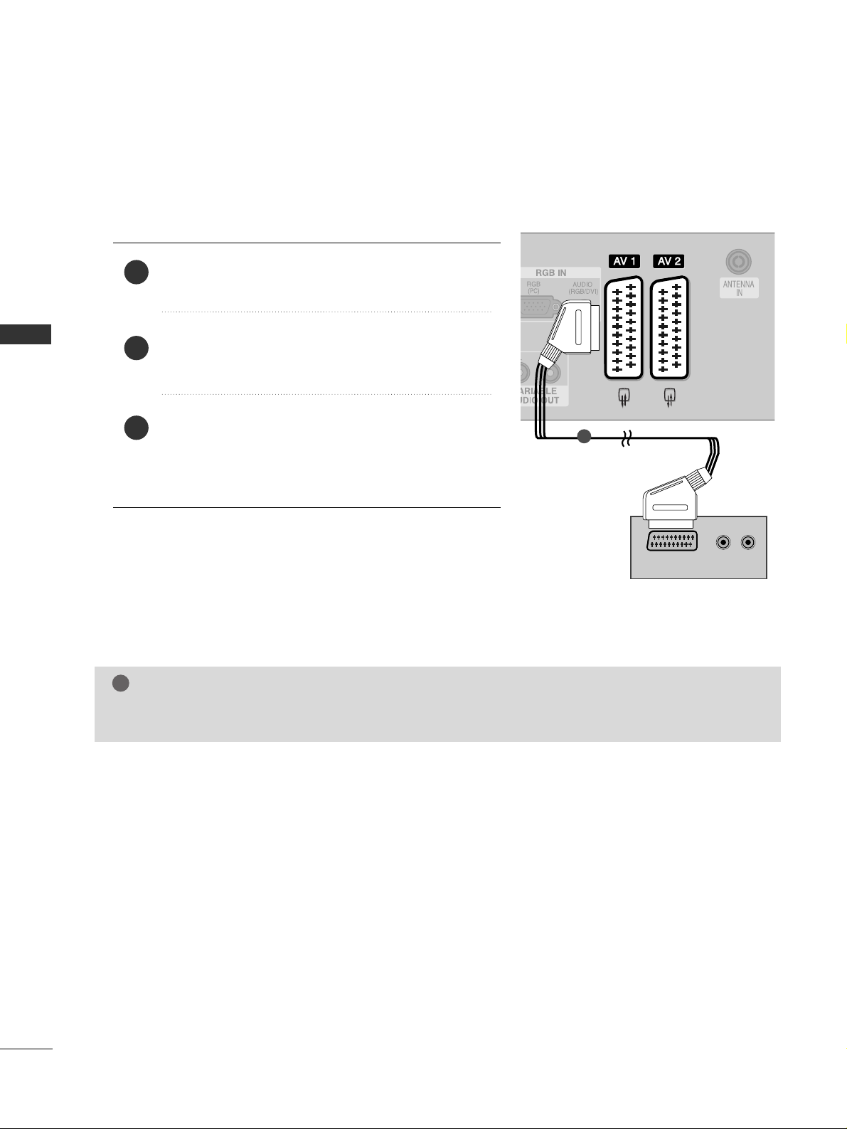
When connecting with a Euro Scart
Connect the Euro scart socket of the VCR to the
AAVV 11
Euro
scart socket on the set.
Insert a video tape into the VCR and press PLAY on the
VCR. (Refer to the VCR owner’s manual.)
Select
AV 1 input source with using the
II NNPP UUTT
button
on the remote control.
If connected to
AAVV 22
Euro scart socket, select
AV 2 input
source.
2
3
1
L/ MONO
R
AUDIO
VIDEO
S-VIDEO
L/ MONO
R
AUDIO
VIDEO
S-VIDEO
(R) AUDIO (L)
AUDIO/
VIDEO
1
NOTE
!
GG
If you want to use the EURO scart cable, you have to use the signal shielded Euro scart cable.
23
EXTERNAL EQUIPMENT SETUP
When connecting with a RCA cable
GG
If both S-VIDEO and VIDEO sockets have been conneced
to the S-VHS VCR simultaneously, only the S-VIDEO can
be received.
NOTE
!
AV IN 3
L/ MONO
R
AUDIO
VIDEO
S-VIDEO
AV IN 3
L/MONOMONO
R
AUDIOAUDIO
VIDEOVIDEO
S-VIDEO
L
R
S-VIDEO
VIDEO
OUTPUT
SWITCH
ANT IN
ANT OUT
AV IN 3
L/MONOMONO
R
AUDIOAUDIO
VIDEOVIDEO
S-VIDEO
L
R
S-VIDEO
VIDEO
OUTPUT
SWITCH
ANT IN
ANT OUT
Connect the
AAUUDDIIOO/VVIIDDEEOO
jacks between TV and
VCR. Match the jack colours (Video = yellow, Audio Left
= white, and Audio Right = red)
Insert a video tape into the VCR and press PLAY on the
VCR. (Refer to the VCR owner’s manual.
)
Select
AV 3 input source using the
II NNPPUUTT
button on
the remote control.
When connecting with an S-Video cable
Connect the S-VIDEO output of the VCR to the
SS--
VVIIDDEEOO
input on the set. The picture quality is
improved; compared to normal composite (RCA cable)
input.
Connect the audio outputs of the VCR to the
AAUUDDIIOO
input jacks on the set.
Insert a video tape into the VCR and press PLAY on
the VCR. (Refer to the VCR owner’s manual.)
Select
AV 3 input source with using the
II NNPP UUTT
but-
ton on the remote control.
1
2
3
2
3
4
1
GG
If you have a mono VCR, connect the audio cable from the
VCR to the
AAUUDDIIOO LL// MMOONNOO
jack of the set.
NOTE
!
1
1 2
24
EXTERNAL EQUIPMENT SETUP
EXTERNAL EQUIPMENT SETUP
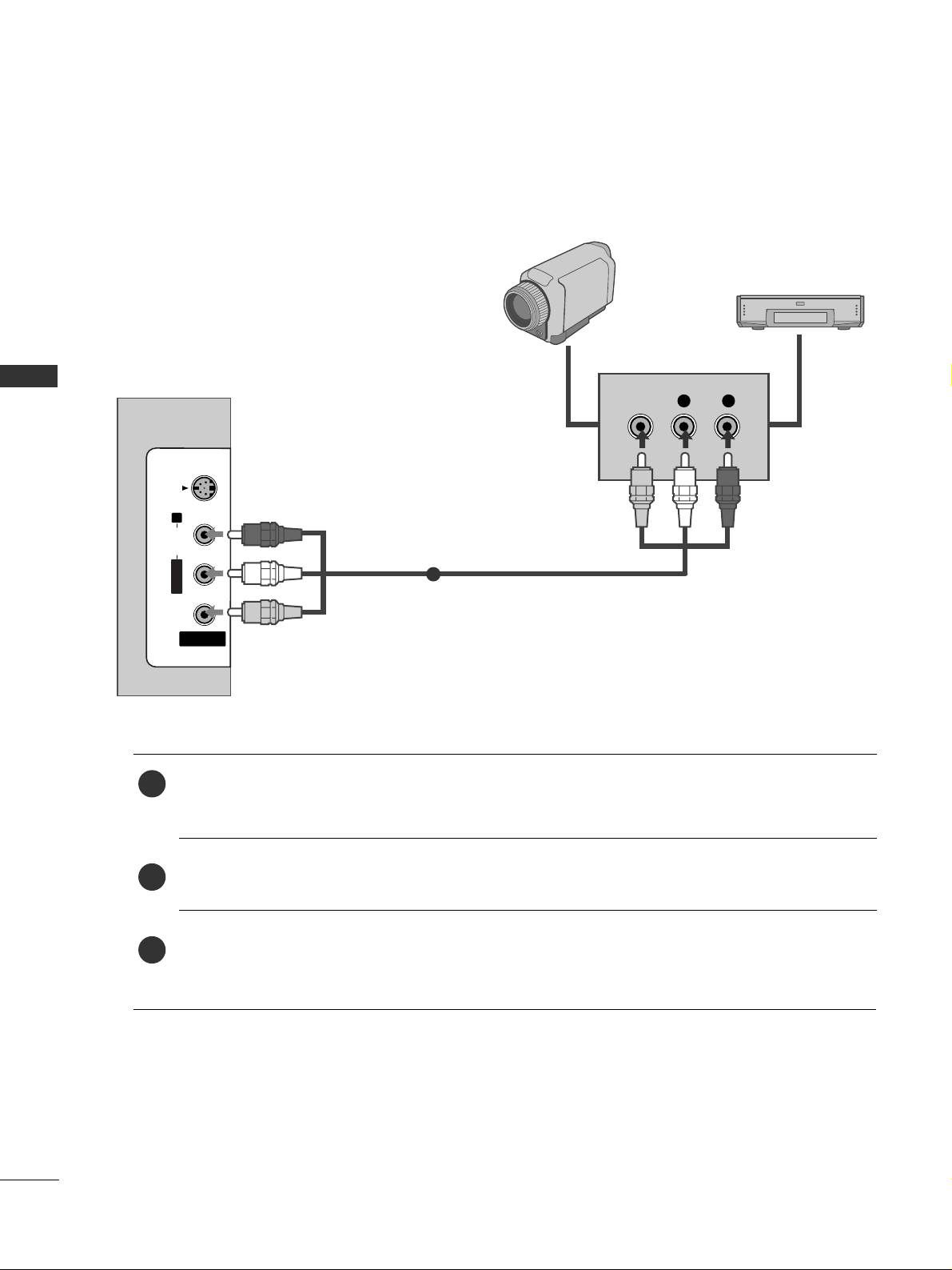
OTHER A/V SOURCE SETUP
Connect the
AAUUDDIIOO/VVIIDDEEOO
jacks between TV and external equipment. Match the jack colours
.
(
Video = yellow, Audio Left = white, and Audio Right = red
)
Select AV 3 input source with using the
II NNPP UUTT
button on the remote control.
Operate the corresponding external equipment.
Refer to external equipment operating guide.
AV IN 3
L/MONOMONO
R
AUDIOAUDIO
VIDEOVIDEO
S-VIDEO
L R
VIDEO
Camcorder
Video Game Set
1
1
2
3
25
EXTERNAL EQUIPMENT SETUP
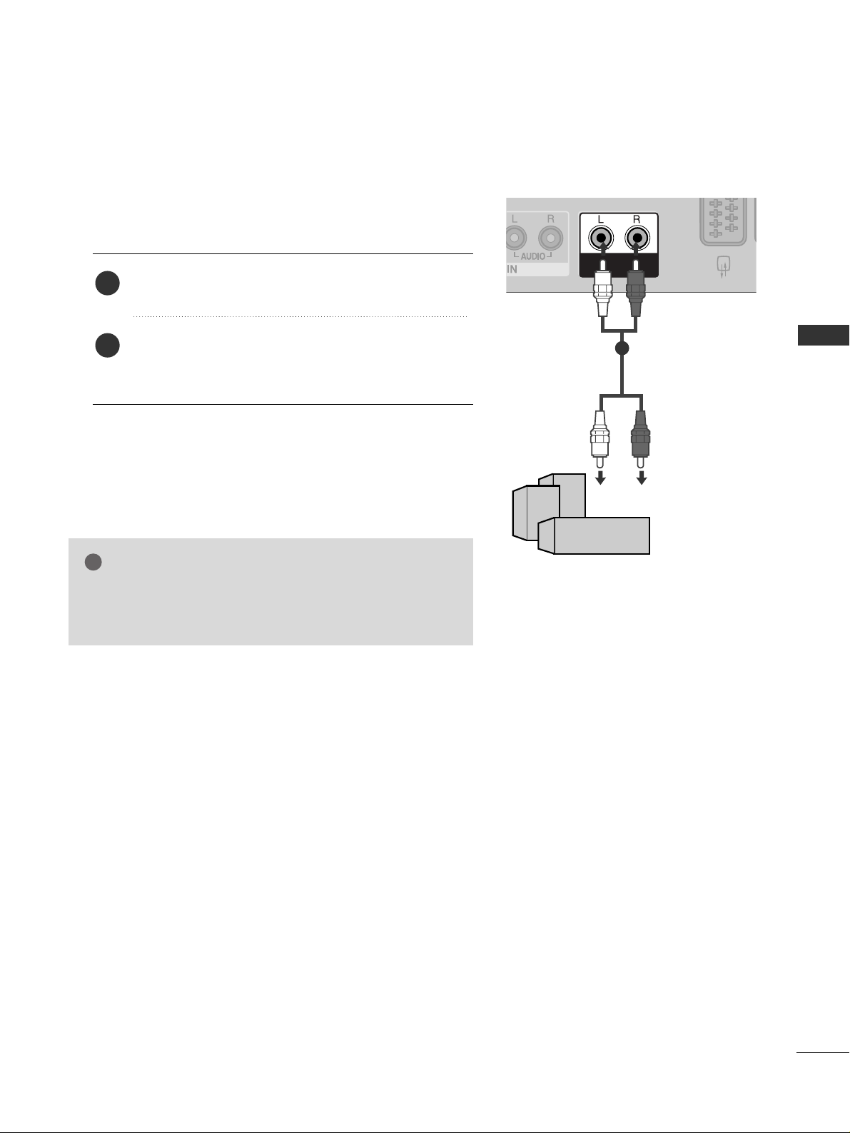
EXTERNAL STEREO
VARIABLE
AUDIO OUT
GG
When connecting with external audio equipments, such as
amplifiers or speakers, please turn the TV speakers off.
(
GG
pp..6633
)
NOTE
!
Use to connected either an external amplifier, or add a subwoofer to your surround sound system.
Connect the input jack of the stereo amplifier to the
VVAARRIIAABBLLEE AAUUDDIIOO OO UUTT
jacks on the set.
Set up your speakers through your analog stereo
amplifier, according to the instructions provided with
the amplifier.
2
1
11
26
EXTERNAL EQUIPMENT SETUP
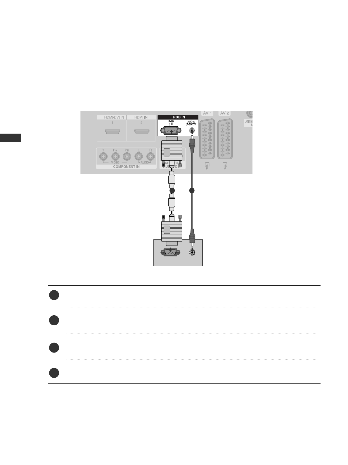
PC SETUP
EXTERNAL EQUIPMENT SETUP
This TV provides Plug and Play capability, meaning that the PC adjusts automatically to the TV's settings.
When connecting with a D-sub 15 pin cable
RGB OUTPUT
AUDIO
Connect the RGB output of the PC to the
RRGGBB ((PPCC
))
jack on the set.
Connect the PC audio output to the
AAUUDDIIOO
jack on the set.
Turn on the PC and the set.
Select
RGB PC input source with using the
II NNPP UUTT
button on the remote control.
2
3
4
1
1
2
 Loading...