

LG Electronics 42LC3R, 37LC3R User Manual

Please read this manual carefully before operating your set.
Retain it for future reference.
Record model number and serial number of the set.
See the label attached on the back cover and quote
this information to your dealer
when you require service.
P/NO : 38289U0577L (0702-REV03)
Printed in Korea
LCD TV
OWNER’S MANUAL
LCD TV MODELS
37LC3R
42LC3R
ht tp://www.lge.com
ht tp://ar.lge.com
Downloaded From TV-Manual.com Manuals

Downloaded From TV-Manual.com Manuals
WARNING
W
Owner Manual
Owner Manual
Owner Manual
Owner Manual
Owner Manual
IMPORTANT SAFETY INSTRUCTIONS
Important safety instructions shall be provided with each apparatus. This information shall be given in a separate booklet or sheet, or be located before any operating instructions in an instruction for installation for
use and supplied with the apparatus.
This information shall be given in a language acceptable to the country where the apparatus is intended to
be used.
The important safety instructions shall be entitled “Important Safety Instructions”. The following safety
instructions shall be included where applicable, and, when used, shall be verbatim as follows. Additional safety information may be included by adding statements after the end of the following safety instruction list. At
the manufacturer’s option, a picture or drawing that illustrates the intent of a specific safety instruction may
be placed immediately adjacent to that safety instruction :
WARNING
Read these instructions.
Keep these instructions.
Heed all warnings.
Follow all instructions.
1
Do not place the product in direct sunlight or
near heat sources such as heat registers,
stove and so on.
This may cause a fire.
Earth wire should be connected.
4
If the earth wire is not connected, there is possible a danger
of electric shock caused by the current leakage.
If grounding methods are not possible, a separate circuit
breaker should be employed and installed by a qualified
electrician.
Do not connect ground to telephone wires, lightning rods
or gas pipe.
Short-circuit
breaker
Power
supplier
WARNING
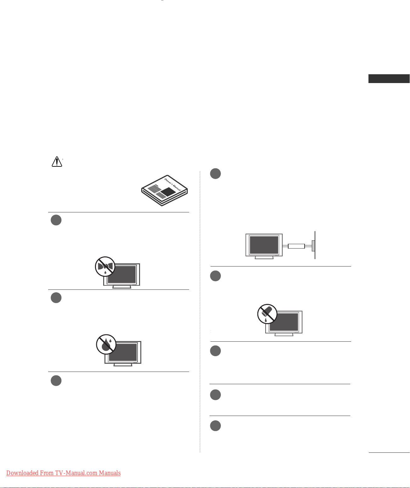
Do not use the product in damp place such
2
as a bathroom or any place where it is likely
to get wet.
This may cause a fire or could give an electric shock.
Bend antenna cable between inside and out-
3
side building to prevent rain from flowing in.
This may cause water damaged inside the product and could
give an electric shock.
Do not placing anything containing liquid on
5
top of the product.
This may cause a fire or could give an electric shock.
6
Wet Location Marking :
Apparatus shall not be exposed to dripping or splashing and
no objects filled with liquids, such as vases, shall be placed
on the apparatus.
Do not insert any object into the exhaust vent.
7
This may cause a fire or could give an electric shock.
Do not place heavy objects on the product.
8
This may cause serious injury to a child or adult.
Downloaded From TV-Manual.com Manuals
1
WARNING
Owner Manual
Owner Manual
W
W
Owner Manual
IMPORTANT SAFETY INSTRUCTIONS
WARNING
WARNING
Do not use water the product while cleaning.
9 1
This may cause damaged the product or could give an electric shock.
In case of smoke or strange smell from the
10
product, switch it off ,unplug it from the wall
outlet and contact your dealer or service
center.
This may cause a fire or could give an electric shock.
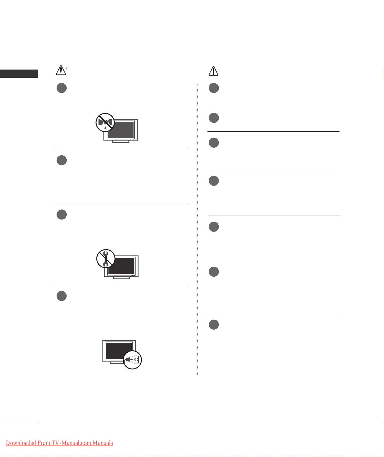
Do not attempt to service the product your-
11
self. Contact your dealer or service center.
This may cause damaged the product or could give an electric
shock.
NOTE
Never touch the power plug with a wet hand.
This may cause an electric shock.
Disconnect from the mains and remove all
2
connections before moving.
Do not place the product in a built-in
3
installation such as a bookcase or rack.
Ventilation required.
When installing the product on a table, be
4
careful not to place the edge of its stand.
This may cause the product to fall, causing serious injury to
a child or adult, and serious damage to the product.
Do not place an outside antenna in the vicinity
5
of overhead power lines or other electric light
or power circuits.
During a lightning thunder, unplug the product
12
from the wall outlet and don’t touch an
antenna cable.
This may cause damaged the product or could give an electric shock.
This may cause an electric shock.
There should be enough distance between an
6
outside antenna and power lines to keep the
former from touching the latter even when
the antenna falls.
This may cause an electric shock.
Do not pull the cord but the plug when
7
unplugging.
This may cause a fire.
2
Downloaded From TV-Manual.com Manuals
W
NOTE
Ensure the power cord doesn’t trail across
8
any hot objects like a heater.
Contact the service center once a year to
13
clean the internal part of the product.
WARNING
This may cause a fire or an electric shock.
Do not plug when the power cord or the plug
9
is damaged or the connecting part of the
power outlet is loose.
This may cause a fire or an electric shock.
Dispose of used batteries carefully to protect
10
a child from eating them.
In case that it eats them, take it to see a doctor immediately.
When moving the product assembled with
11
speakers do not carry holding the speakers.
This may cause the product to fall, causing serious injury to
a child or adult, and serious damage to the product.
Unplug this product from the wall outlet
12
before cleaning. Do not use liquid cleaners or
aerosol cleaners.
Accumulated dust can cause mechanical failure.
The distance between eyes and the screen
14
should be about 5 - 7 times as long as diagonal length of the screen.
If not, eyes will strain.
Unplug the product from the wall outlet when
15
it is left unattended and unused for long periods
of time.
Accumulated dust may cause a fire or an electric shock from
deterioration or electric leakage.
Only use the specified batteries.
16
This make cause damaged the product or could give an
electric shock.
This may cause damaged the product or could give an electric
shock.
Downloaded From TV-Manual.com Manuals
3

CONTENTS
WARNING
INTRODUCTION
Accessories
Controls / Connection Options
CONTENT
Remote Control Key Functions
INSTALLATION
Wire Arrangement
Attaching the TV to a Wall
Desktop Pedestal Installation
CONNECTIONS & SETUP
Antenna Connection . . . . . . . . . . . . . . . . . . . . . . . . . . . . . . . . . . . . . . . .12
VCR Setup
External Equipment Connections
External Stereo
AV out Setup
DVD Setup
HDSTB Setup
PC Setup
BASIC OPERATION
Turning the TV On . . . . . . . . . . . . . . . . . . . . . . . . . . . . . . . . . . . . . . . . . . 25
Channel Selection
Volume Adjustment
On-Screen Menus Language Selection
SPECIAL FUNCTIONS
. . . . . . . . . . . . . . . . . . . . . . . . . . . . . . . . . . . . . . . . . . . . . . . . 1-
. . . . . . . . . . . . . . . . . . . . . . . . . . . . . . . . . . . . . . . . . . . . . . . . . . . . . . 5
. . . . . . . . . . . . . . . . . . . . . 6-7
. . . . . . . . . . . . . . . . . . . . . . .
. . . . . . . . . . . . . . . . . . . . . . . . . . . . . . . . . . . . . . . . . . .10
. . . . . . . . . . . . . . . . . . . . . . . . . . . . . . . . 11
. . . . . . . . . . . . . . . . . . . . . . . . . . . .11
. . . . . . . . . . . . . . . . . . . . . . . . . . . . . . . . . . . . . . . . . . . . . . . .13-14
. . . . . . . . . . . . . . . . . . . . . . 15
. . . . . . . . . . . . . . . . . . . . . . . . . . . . . . . . . . . . . . . . . . . . . . . .15
. . . . . . . . . . . . . . . . . . . . . . . . . . . . . . . . . . . . . . . . . . . . . . . . . . 16
. . . . . . . . . . . . . . . . . . . . . . . . . . . . . . . . . . . . . . . . . . . . . . . . .
. . . . . . . . . . . . . . . . . . . . . . . . . . . . . . . . . . . . . . . . . . .19-21
. . . . . . . . . . . . . . . . . . . . . . . . . . . . . . . . . . . . . . . . . . . . . . . . . . . 22-24
. . . . . . . . . . . . . . . . . . . . . . . . . . . . . . . . . . . . . . . . . . .25
. . . . . . . . . . . . . . . . . . . . . . . . . . . . . . . . . . . . . . . . . 25
. . . . . . . . . . . . . . 26
8-9
17-18
3
Manual Program : Adding /Deleting Channels
Fine Tuning Adjustment
Booster
. . . . . . . . . . . . . . . . . . . . . . . . . . . . . . . . . . . . . . . . . . . . . . . . . . . . . . . . . . 33
Favorite Channels setup
. . . . . . . . . . . . . . . . . . . . . . . . . . . . . . . . . . .
. . . . . . . . . . . . . . . . . . . . . . . . . . . . . . . . . . . 34
. . . 31
32
Picture Adjustment
Auto Picture Control (APC) . . . . . . . . . . . . . . . . . . . . . . . . . . . . .
Manual Picture Control (APC-User Option)
Auto Color Temperature Control (ACC)
. . . . . . . . . . . 37
Manual Color Temperature Control (ACC-User Option)
. . . . . . . . . . . . . . . . . . . . . . . . . . . . . . . . . . . . . . . . . . . . . . . . . . . . . . . . . . . . . . . . . 39
XD
Advanced-Cinema Mode Setup
Advanced-Black Level
Reset
. . . . . . . . . . . . . . . . . . . . . . . . . . . . . . . . . . . . . . . . . . . . . . . . . . . . . . . . . . . . .42
. . . . . . . . . . . . . . . . . . . . . . . . . . . . . . . . . . . . . .41
. . . . . . . . . . . . . . . . . . . . . . . .40
35
. . . . . . 36
. . 38
Sound Adjustment
Digital Auto Sound Processing (DASP) . . . . . . . . . . . . . 43
Manual Sound Control (DASP-User Option)
Auto Volume Leveler (AVL)
Balance Adjustment
TV Speakers On/Off Setup
Stereo/SAP Broadcasts Setup
. . . . . . . . . . . . . . . . . . . . . . . . . . . . . . 45
. . . . . . . . . . . . . . . . . . . . . . . . . . . . . . . . . . . . . . . . 46
. . . . . . . . . . . . . . . . . . . . . . . . . . . . . . 47
. . . . . . . . . . . . . . . . . . . . . . . . . . 48
. . . . .44
Time Setting
Clock Setup . . . . . . . . . . . . . . . . . . . . . . . . . . . . . . . . . . . . . . . . . . . . . . . . . . . . 49
On/Off Timer Setup
Auto Off
Sleep Timer
. . . . . . . . . . . . . . . . . . . . . . . . . . . . . . . . . . . . . . . . . . . . . . . . . . . . . . . . .51
. . . . . . . . . . . . . . . . . . . . . . . . . . . . . . . . . . . . . . . . . . . . . . . . . . . .52
. . . . . . . . . . . . . . . . . . . . . . . . . . . . . . . . . . . . . . . 50
Special Features
Key Lock
Closed Captions
XD Demo
. . . . . . . . . . . . . . . . . . . . . . . . . . . . . . . . . . . . . . . . . . . . . . . . . . . . . . . . .53
. . . . . . . . . . . . . . . . . . . . . . . . . . . . . . . . . . . . . . . . . . . . . 54
. . . . . . . . . . . . . . . . . . . . . . . . . . . . . . . . . . . . . . . . . . . . . . . . . . . . . . . 55
PIP/Double Window/POP
- Watching PIP/Double Window/POP . . . . . . . . . . . . . . . 27
- TV Program Selection for PIP
- Selecting an Input Signal Source
for PIP/Double Window
- Sub Picture Sizes Adjustment (PIP mode only) 28
- Moving the PIP Sub Picture(PIP mode only)
- Swapping the PIP/Double Window
- Adjusting PIP Transparency (PIP mode only)
- POP (Picture-out-of-Picture: Channel Scan)
TV MENU
On Screen Menus Selection and Adjustment . . . . 29
Setup(Channel)
Auto Program : Channel Search . . . . . . . . . . . . . . . . . . . . . . . . 30
4
Downloaded From TV-Manual.com Manuals
. . . . . . . . . . . . . . . . . . . . . . . . . 27
. . . . . . . . . . . . . . . . . . . . . . . . . . . . . . . . .27
. . . 28
. . . . . . . . . . . . . . . . . 28
. . . 28
. . . 28
Screen Adjustment
Auto Configure (RGB[PC] Mode Only) . . . . . . . . . . . . 56
Manual Configure
Selecting XGA Mode
Aspect Ratio Control (ARC)
Initializing (Reset to Original Factory Settings)
. . . . . . . . . . . . . . . . . . . . . . . . . . . . . . . . . . . . . . . . . . . . 57
. . . . . . . . . . . . . . . . . . . . . . . . . . . . . . . . . . . . . . . 58
. . . . . . . . . . . . . . . . . . . . . . . . . . . . .59
. . 60
APPENDIX
External Control Device Setup . . . . . . . . . . . . . . . . . . . .61-67
IR Codes
Programming the Remote Control
Programming Codes
Troubleshooting Checklist
Maintenance
Product Specifications
. . . . . . . . . . . . . . . . . . . . . . . . . . . . . . . . . . . . . . . . . . . . . . . . .68-69
. . . . . . . . . . . . . . . . . . .70
. . . . . . . . . . . . . . . . . . . . . . . . . . . . . . . . .70-71
. . . . . . . . . . . . . . . . . . . . . . . . . . 72-73
. . . . . . . . . . . . . . . . . . . . . . . . . . . . . . . . . . . . . . . . . . . . . . . . . . . 74
. . . . . . . . . . . . . . . . . . . . . . . . . . . . . . . . . . . . . 75
INTRODUCTION
Owner's Manual
1.5V 1.5V
ENTER
INPUT
TVTV
INPUT
PIP CH- PIP CH+
PIP INPUT
DVD
ARC
EXIT
VOL
REVIEW
MUTE
CH
SLEEP
MEMORY/ERASE
MENU
CAPTION
PIP SIZE
POSTION
VCR
POWER
123
456
789
*
0
FCR
MTS
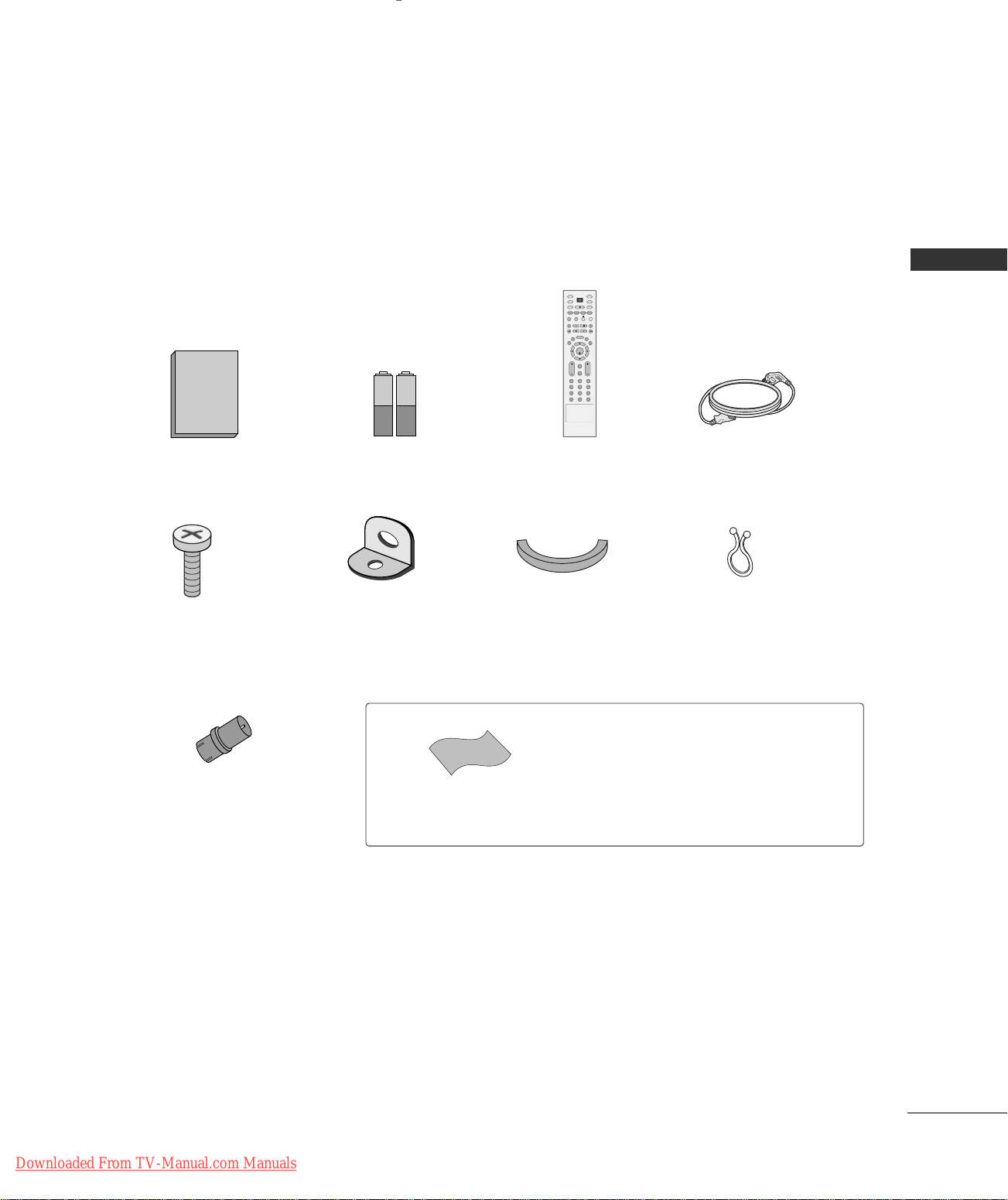
ACCESSORIES
Ensure that the following accessories are included with your product. If an accessory is missing, please contact the dealer where you purchased the product.
INTRODUCTION
Owner’s Manual Batteries
(some models)
2-TV Bracket Bolts
2-TV Brackets,
2-Wall Brackets
RF Adapter
You must connect it to the antenna
wire after fixing in Antenna Input.
This adapter is only supplied in
Argentina.
Remote Control Power Cord
Cable Management
(Refer to p.10)
Polishing Cloth
Polish the screen with the cloth.
Twister Holder
Arrange the wires
with the twister holder.
* Slightly wipe stained spot on the exterior only with
the polishing cloth for the product exterior if there is
stain or fingerprint on surface of the exterior.
* Do not wipe roughly when removing stain. Please be
cautions of that excessive power may cause scratch or
discoloration.
Downloaded From TV-Manual.com Manuals
5
INTRODUCTION
CHCH
VOLVOL
ENTERENTER
MENUMENU
INPUTINPUT
CONTROLS
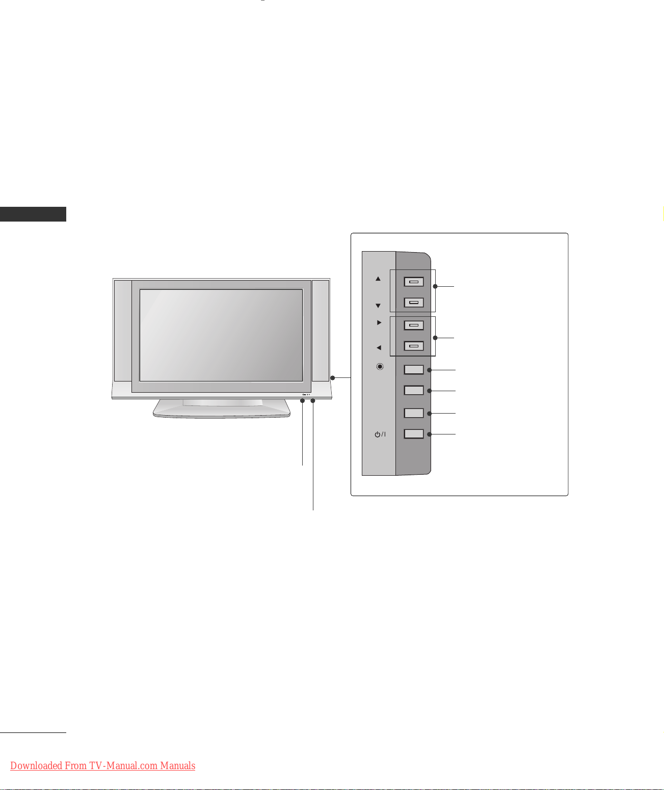
■
This is a simplified representation of the front panel. Here shown may be somewhat different from your TV.
Front Panel Controls
INTRODUCTION
CHANNEL Buttons
Remote Control Sensor
Power Standby Indicator
Illuminates red in standby mode.
Illuminates white when the set is switched on.
VOLUME Buttons
ENTER Button
R
MENU Button
INPUT Button
POWER Button
6
Downloaded From TV-Manual.com Manuals
CONNECTION OPTIONS
VIDEO
AV IN 2
L/MONO R
AUDIO
MONO
( )
AUDIO
RS-232C IN
(CONTROL & SERVICE)
ANTENNA
IN
VIDEO
S-VIDEO
AV IN 1
RGB IN
AV OUT
VIDEO
AUDIO
HDMI IN
2
1 (DVI)
REMOTE
CONTROL
IN
RGB
(PC/DTV)
AUDIO
(RGB/DVI)
AUDIO OUT
VARIABLE
COMPONENT IN
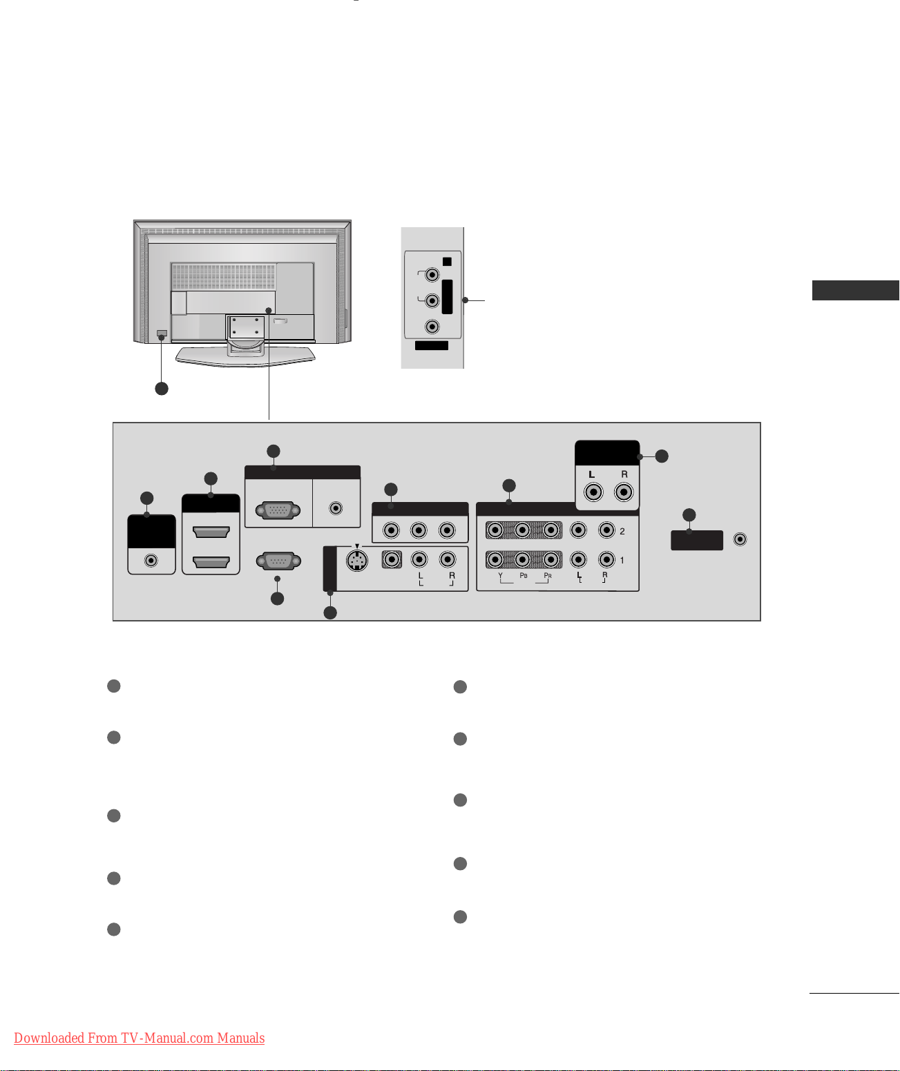
Back Connection Panel
AUDIO Input
Connections are available for listening
stereo sound from an external device.
10
3
2
1
4
1
Remote Control Port
Connect your wired remote control.
VIDEO Input
INTRODUCTION
Connects the video signal from a video
device.
8
6
5
6
7
9
AV OUT
Connect a second TV or monitor.
HDMI IN
2
Connect a HDMI signal.
Or DVI(VIDEO)signal to the this port with a DVI
to HDMI cable.
3
RGB/AUDIO IN
Connect the output from a settop box or PC to
the appropriate input port.
4
RS-232C IN (CONTROL &SERVICE) PORT
Connect to the RS-232C port on a PC.
5
AV (Audio/Video) IN 1
Connect audio/video output from an external
device to these jacks.
S-VIDEO
Connect S-Video out from an S-VIDEO device.
Downloaded From TV-Manual.com Manuals
COMPONENT IN
7
Connect a component video/audio device to
these jacks.
8
VARIABLE AUDIO OUT
Connect an external amplifier or add a subwoofer
to your surround sound system.
9
ANTENNA IN
Connect over-the air signals to this jack.
Power Cord Socket
10
For operation with AC power.
Caution: Never attempt to operate the TV on DC
power.
7
INTRODUCTION
ENTER
INPUT
TVTV
INPUT
PIP CH- PIP CH+
PIP INPUT
DVD
ARC
EXIT
VOL
REVIEW
MUTE
CH
SLEEP
MEMORY/ERASE
MENU
CAPTION
PIP SIZE
POSTION
VCR
POWER
123
456
789
*
0
MTS
FCR
SWAP
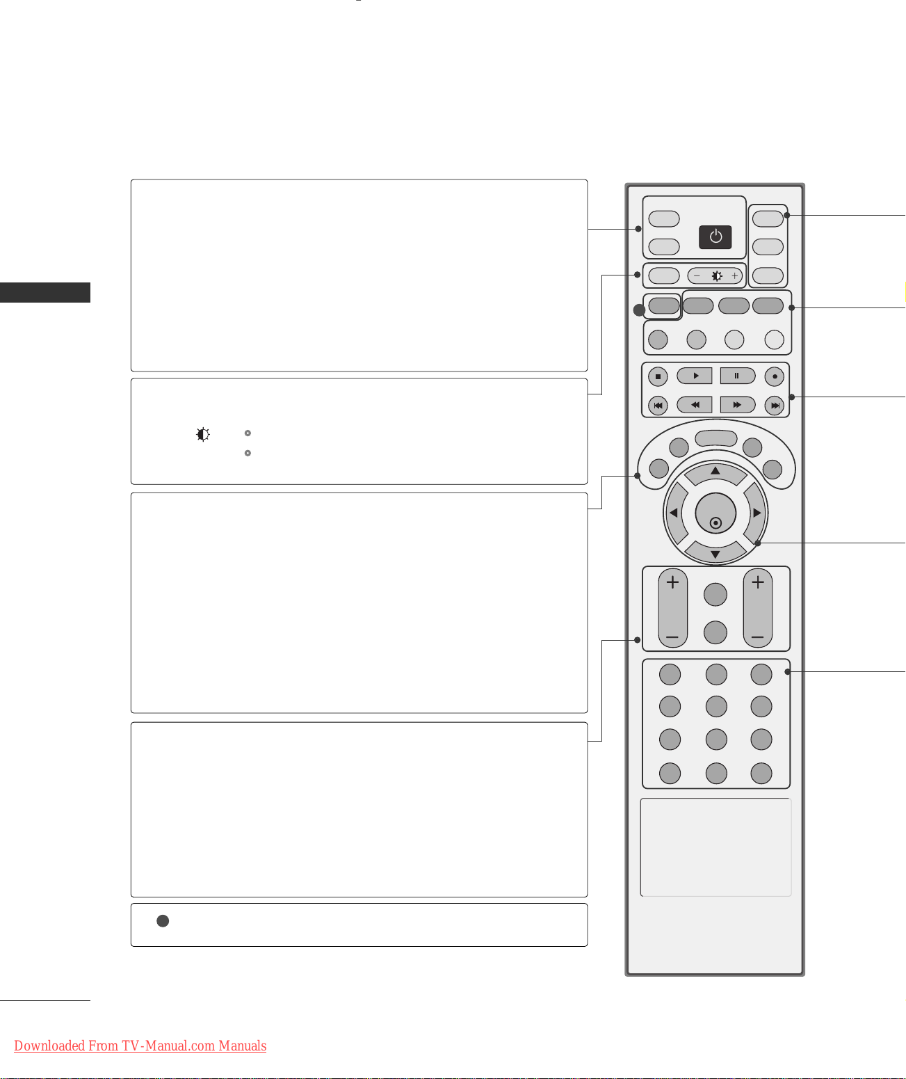
REMOTE CONTROL KEY FUNCTIONS
When using the remote control, aim it at the remote control sensor on the TV.
INTRODUCTION
MEMORY/ERASE
POWER
TV INPUT
INPUT
MENU
Turns your TV or any other programmed equipment on
or off, depending on mode.
Returns to the TV mode.
If you press the button once, the input source OSD will
appear on screen as shown. Press the
DD/ EE
then ENTER button to select the desired input source
(TV, AV1, AV2, Component 1, Component 2, RGB,
HDMI1/DVI, or HDMI2).
Change the aspect ratio.
ARC
Adjusts brightness on screen.
+/-
pp..5599
GG
It returns to the default settings brightness by changing
mode source.
EXIT
Clears all on-screen displays and returns to TV viewing
from any menu.
Memorizes or erases selected channel.
GG
Displays the main menu.
button and
pp..3311
1
MTS
Selects the MTS sound:
SLEEP
VOLUME UP
Select the amount of time before your TV turns off automatically.
Increases/decreases the sound level.
/DOWN
REVIEW
MUTE
CHANNEL
UP/DOWN
CAPTION
1
Tune to the last channel viewed.
Switches the sound on or off.
Select available channels.
Selects CAPTION mode.
8
Downloaded From TV-Manual.com Manuals
GG
pp..5522
MMoonnoo, SSttee rreeoo
pp..5544
GG
, or
SSAA PP
pp..4488
.
GG
R
TVD/A
INPUT
INPUT
DVD
ARC
TEXT PIP
GUIDE
INFO
VCR
POWER
MODE
Selects the remote operating mode: TV, VCR, DVD.
PIP
SIZE
POSITION
PIP CH - /+
SWAP
PIP INPUT
VCR/DVD
control buttons
THUMBSTICK
(Up/Down/Left
/Right/ENTER)
NUMBER button
*
GG
pp..2277
GG
pp..2277
Switches the sub picture PIP, DW mode.
Adjusts the sub picture size.
Moves the sub picture.
GG
GG
pp..2288
pp..2288
Selects a channel for the sub picture.
Exchanges the main/sub images in PIP/Double window mode.
Select the connected input source for the sub-picture.
GG
pp..2277
Control video cassette recorders or DVD players.
Navigate the on-screen menus and adjust the system settings to your preference.
Not functional
INTRODUCTION
Scroll through the programmed Favorite channels.
FCR
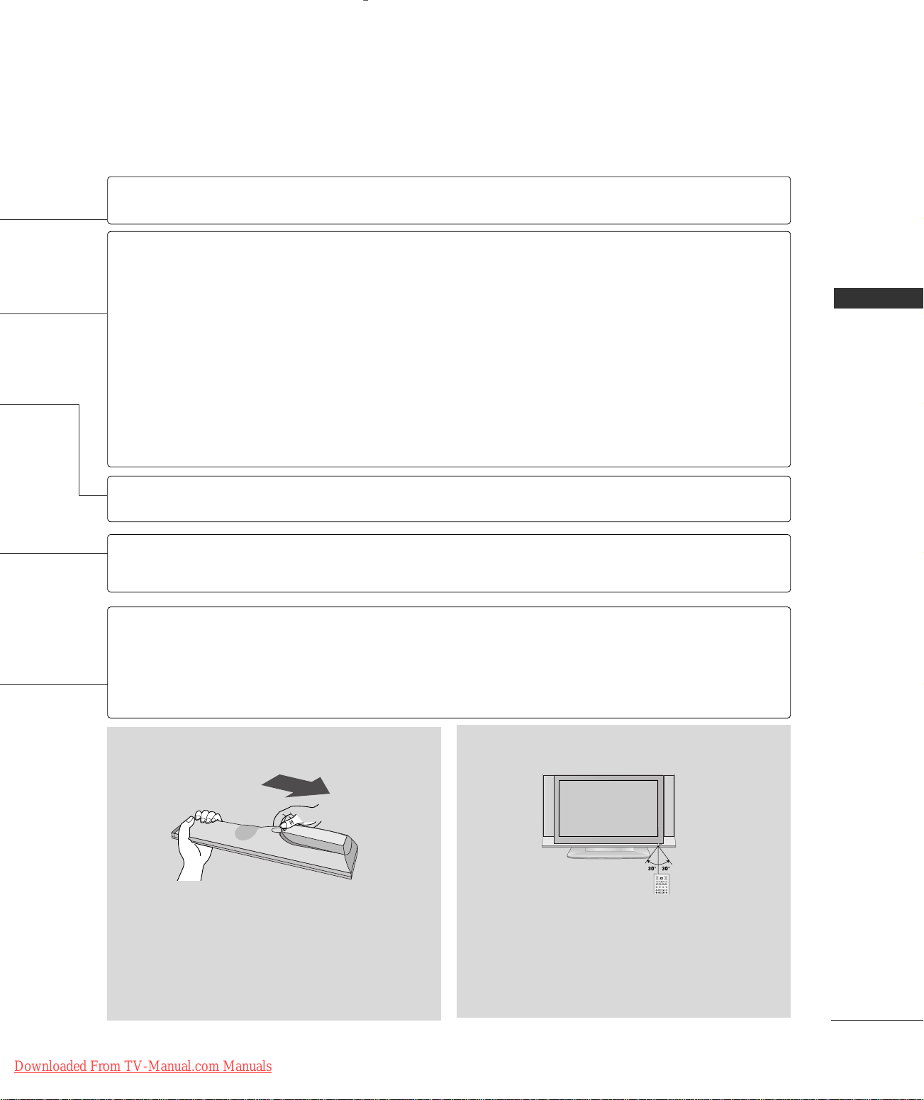
Installing Batteries Remote control effective range
■
Open the battery compartment cover on the back
side and install the batteries matching correct
polarity (+with +,-with -).
■
Install two 1.5V AA batteries. Don’t mix old or
used batteries with new ones.
■
Close cover.
Downloaded From TV-Manual.com Manuals
■
Use a remote control up to 7 meters distance and
30 degree (left/right) within the receiving unit
scope.
■
Dispose of used batteries in a recycle bin to
preserve environment.
9
INSTALLATION
!
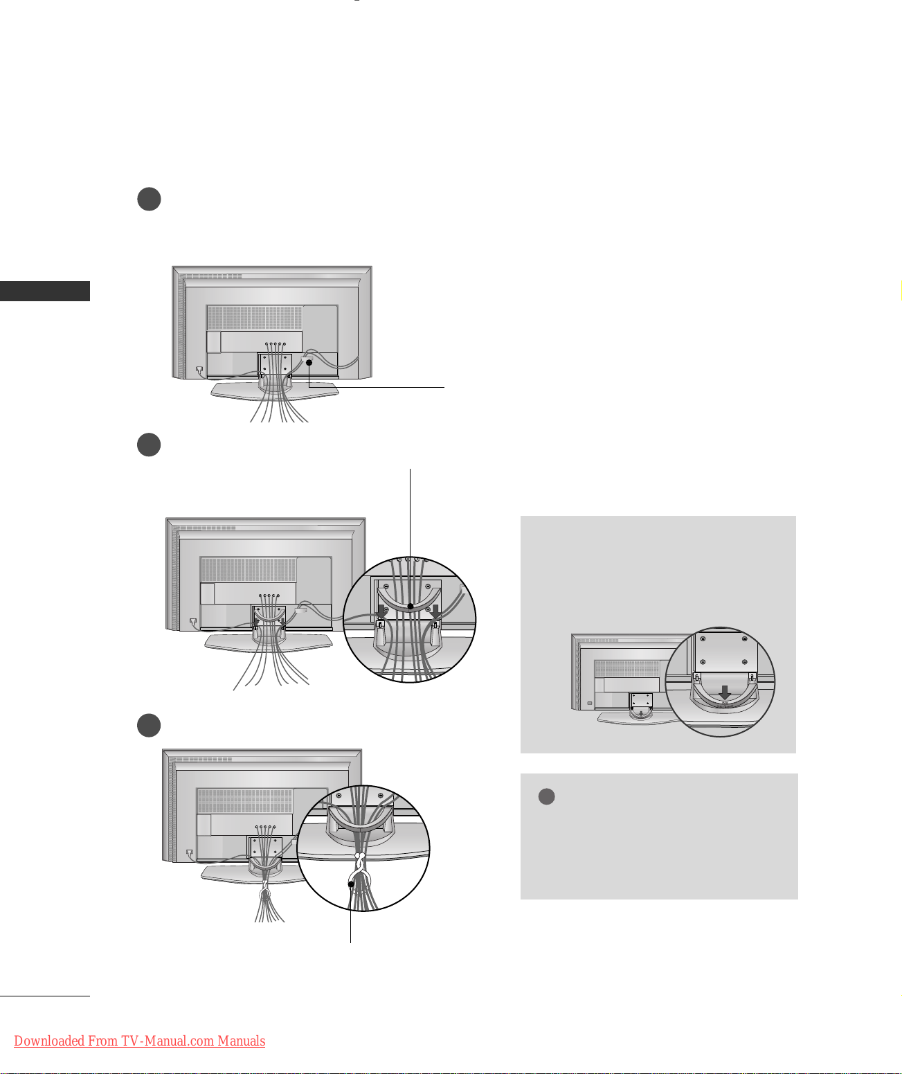
WIRE ARRANGEMENT
Connect the cables as necessary.
1
After connecting the cables neatly, arrange the cables to the Cable Holder.
To connect an additional equipment, see the
INSTALLATION
CCOONNNNEECCTTIIOONNSS&& SSEETTUUPP
section.
CABLE HOLDER (For
Install the CABLE MANAGEMENT as shown.
2
CABLE MANAGEMENT
Bundle the cables using the supplied twister holder.
3
42LC3R
)
How to remove the CABLE
MANAGEMENT
Push the CABLE MANAGEMENT
GG
downward.
NOTE
Do not hold the CABLE MANAGEMENT
GG
when moving the product.
- If the product is dropped, you may be
injured or the product may be broken.
10
Downloaded From TV-Manual.com Manuals
TWISTER HOLDER
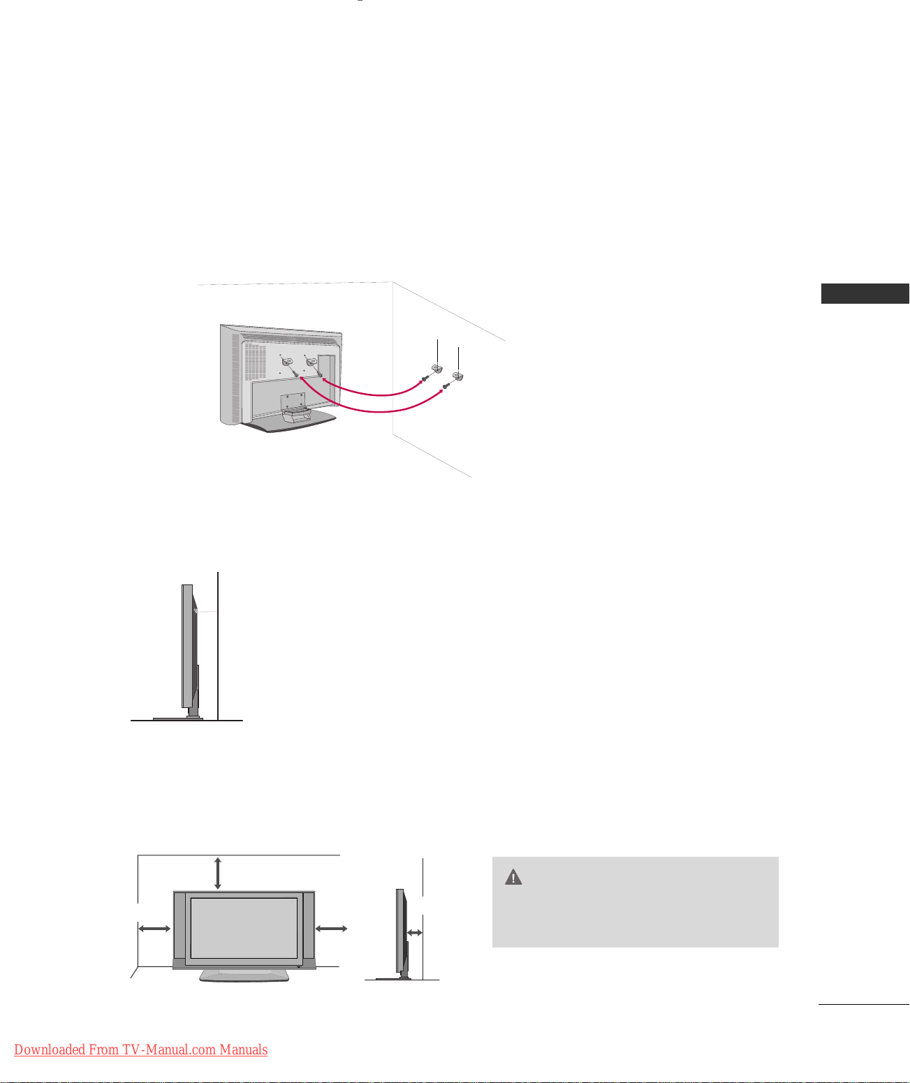
ATTACHING THE TV TO A WALL
R
We recommend that you set up the TV close to a wall so it cannot fall over if pushed backwards.
Additionally, we recommend that the TV be attached to a wall so it cannot be pulled in a forward direction,
potentially causing injury or damaging the product.
Caution: Please make sure that children don’t climb on or hang from the TV.
■
Insert the eye-bolts (or TV brackets and bolts) to tighten the product to the wall as shown in the picture.
* If your product has the bolts in the eye-bolts position before inserting the eye-bolts, loosen the bolts.
Secure the wall brackets with the bolts (not provided as parts of the product, must purchase separately) on
the wall. Match the height of the bracket that is mounted on the wall to the holes in the product.
Ensure the eye-bolts or brackets are tightened securely.
INSTALLATION
■
Use a sturdy rope (not provided as parts of the product, must purchase
separately) to tie the product. It is safer to tie the rope so it becomes
horizontal between the wall and the product.
DESKTOP PEDESTAL INSTALLATION
For proper ventilation, allow a clearance of 4inches on each side from the wall.
4 inches
4 inches
4 inches
4 inches
CAUTION
Ensure adequate ventilation by follow-
GG
ing the clearance recommendations.
Downloaded From TV-Manual.com Manuals
11
CONNECTIONS & SETUP
ANTENNA
IN
!
ANTENNA
IN
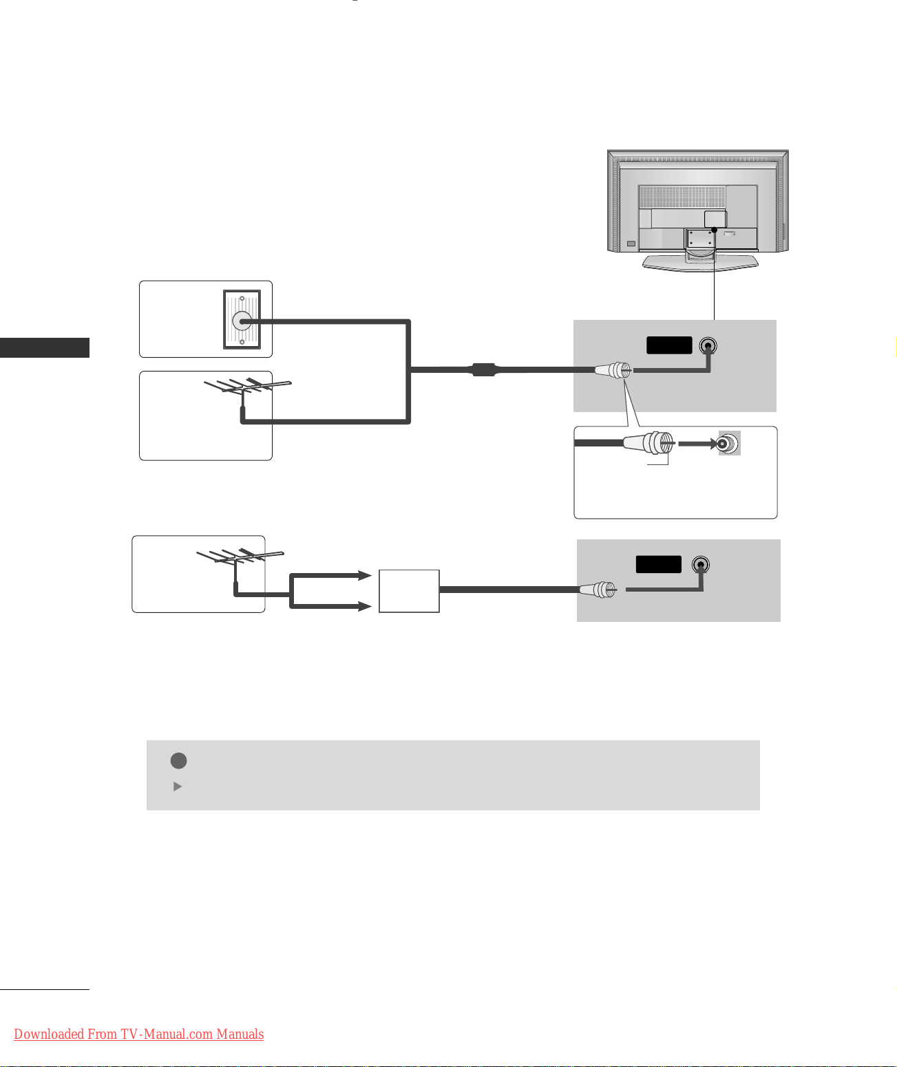
ANTENNA CONNECTION
■
For optimum picture quality, adjust antenna direction.
■
An antenna cable and converter are not supplied.
Multi-family Dwellings/Apartments
Wall
Antenna
Socket
CONNECTIONS & SETUP
Outdoor
Antenna
(VHF, UHF)
(Connect to wall antenna socket)
Single-family Dwellings /Houses
(Connect to wall jack for outdoor antenna)
RF Coaxial Wire (75 ohm)
Bronze Wire
Be careful not to bend the bronze
wire when connecting the antenna.
UHF
Antenna
VHF
■
To improve the picture quality in a poor signal area, please purchase a signal amplifier and install properly.
■
If the antenna needs to be split for two TV’s, install a 2-Way Signal Splitter.
■
If the antenna is not installed properly, contact your dealer for assistance.
Signal
Amplifier
NOTE
The TV will let you know when the analog and cable channel scans are complete.
12
Downloaded From TV-Manual.com Manuals
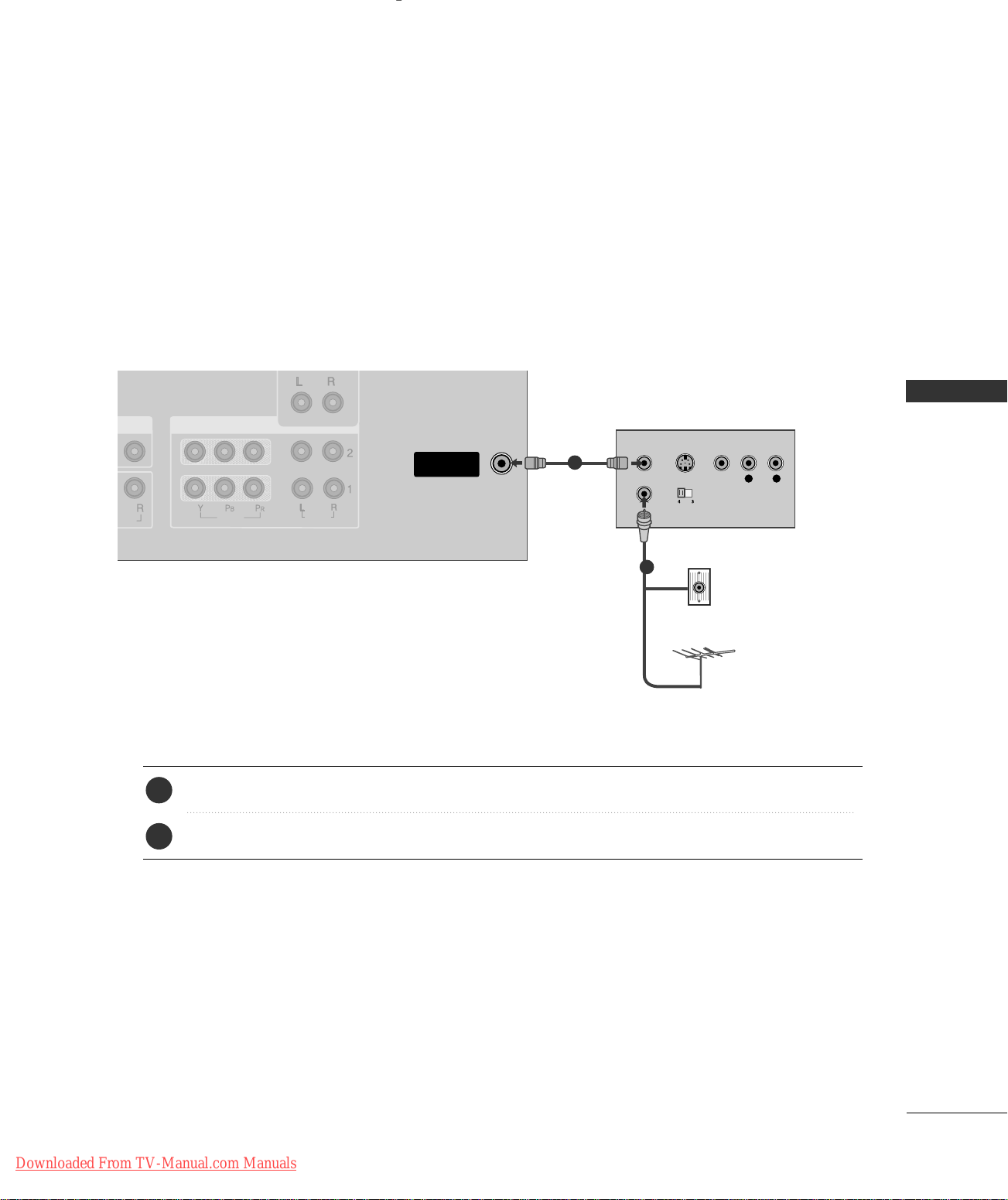
VCR SETUP
NO
)
ANTENNA
IN
VIDEO
AUDIOUDIO
COMPONENT IN
L R
S-VIDEO VIDEO
OUTPUT
SWITCH
ANT IN
ANT OUT
■
To avoid picture noise (interference), leave an adequate distance between the VCR and TV
■
If the 4:3 picture format is used; the fixed images on the sides of the screen may remain visible on the
screen. This phenomenon is common to all manufactures and in consequence the manufactures warranty
does not cover the product bearing this phenomenon.
When connecting with an antenna
1
Wall Jack
2
CONNECTIONS & SETUP
1. How to connect
2. How to use
Antenna
AAnn tteennnnaa
socket on the set.
Connect the RF antenna out socket of the VCR to the
1
Connect the antenna cable to the RF antenna in socket of the VCR.
2
■
Set VCR output switch to 3 or 4 and then tune TV to the same channel number.
■
Insert a video tape into the VCR and press PLAY on the VCR. (Refer to the VCR owner’s manual.
)
Downloaded From TV-Manual.com Manuals
13
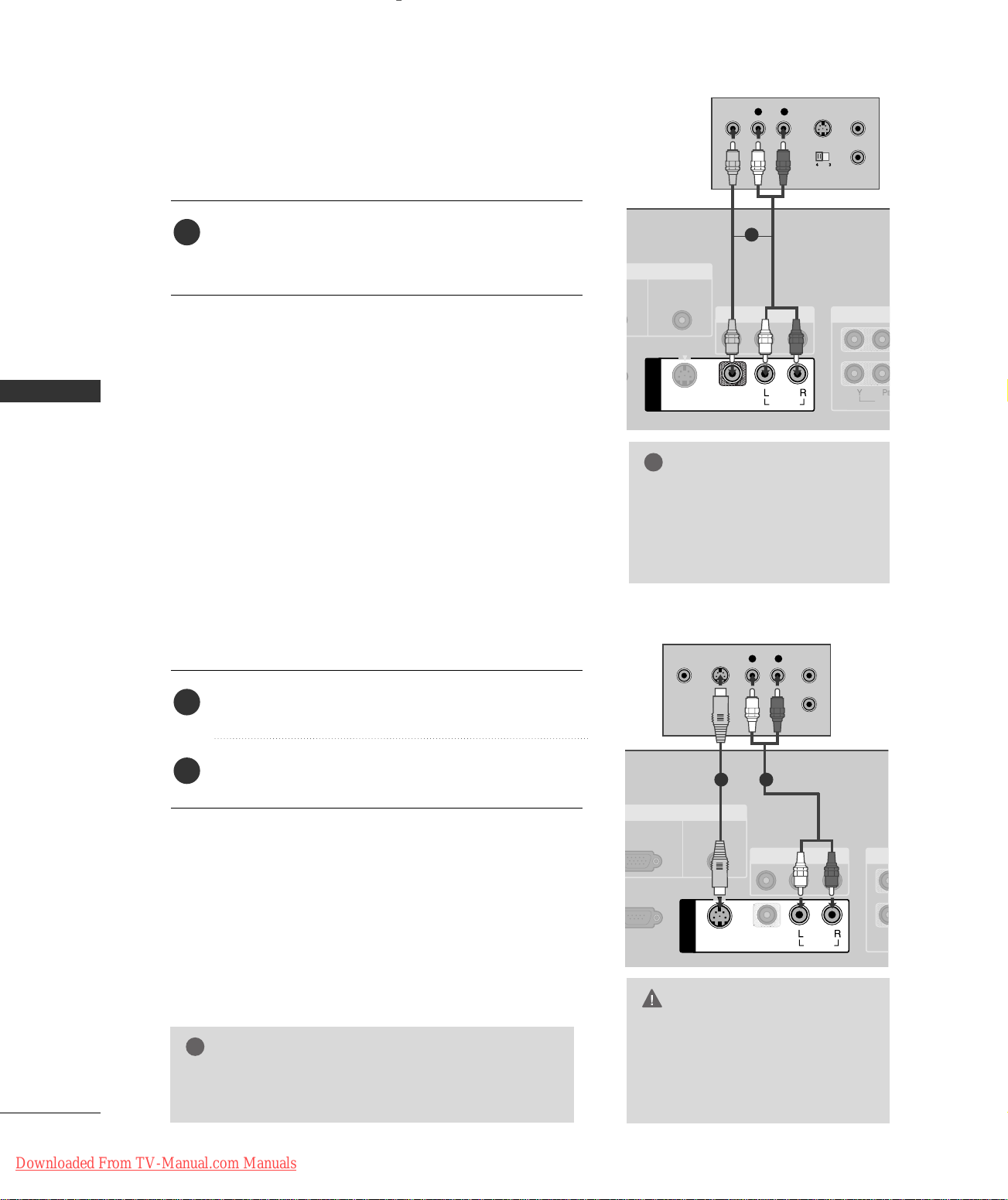
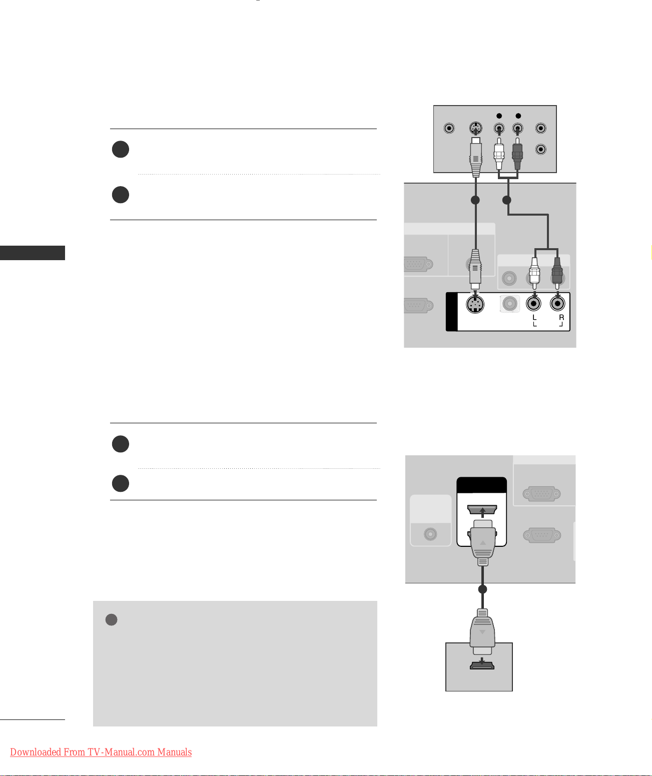
When connecting with a RCA cable
!
VIDEO
AUDIO
ICE)
S-VIDEO
AV IN 1
AV OUT
VIDEVIDEO
AUDIO
AUDIO
(RGB/DVI)
COMPON
MONO
( )
AUDIO
VIDEO
L R
S-VIDEOVIDEO
OUTPUT
SWITCH
ANT IN
ANT OUT
VIDEO
AUDIO
&
SERVICE)
VIDEO
AV IN 1
RGB IN
AV OUT
VIDEO
AUDIO
RGB
AUDIO
(RGB/DVI)
CO
VIDEO
AUDIO
MONO
( )
AUDI O
S-VIDEO
L R
S-VIDEOVIDEO
OUTPUT
SWITCH
ANT IN
ANT OUT
!
CONNECTIONS & SETUP
1. How to connect
Connect the
1
VCR. Match the jack colors (Video = yellow, Audio Left
AAUUDDIIOO/VVIIDDEEOO
jacks between TV and
= white, and Audio Right = red)
2. How to use
■
Insert a video tape into the VCR and press PLAY on the
AAVV22
)
IINNPPUUTT
button on
input source.
VCR. (Refer to the VCR owner’s manual.
■
Select
AAVV11
input source with using the
the remote control.
■
If connected to
When connecting with an S-Video cable
AAVV IINN22
, select
1
NOTE
If you have a mono VCR, con-
GG
nect the audio cable from the
VCR to the
LL//MM OO NNOO
AAUUDDIIOO
jack of the set.
1. How to connect
Connect the S-VIDEO output of the VCR to the
1
SS --VVIIDDEEOO
Connect the audio outputs of the VCR to the
2
input jacks on the set.
2. How to use
14
Downloaded From TV-Manual.com Manuals
■
Insert a video tape into the VCR and press PLAY on the VCR.
(
Refer to the VCR owner’s manual.
■
Select
AAVV11
the remote control.
■
If connected to
NOTE
The picture quality is improved: compared to normal
GG
composite (RCA cable) input.
input on the set.
input source with using the
AAVV IINN22
, select
AAVV22
)
IINNPPUUTT
input source.
AAUUDDIIOO
button on
1 2
CAUTION
Do not connect to both Video
GG
and S-Video at the same time. In
the event that you connect both
Video and the S-Video cables,
only the S-Video will work.
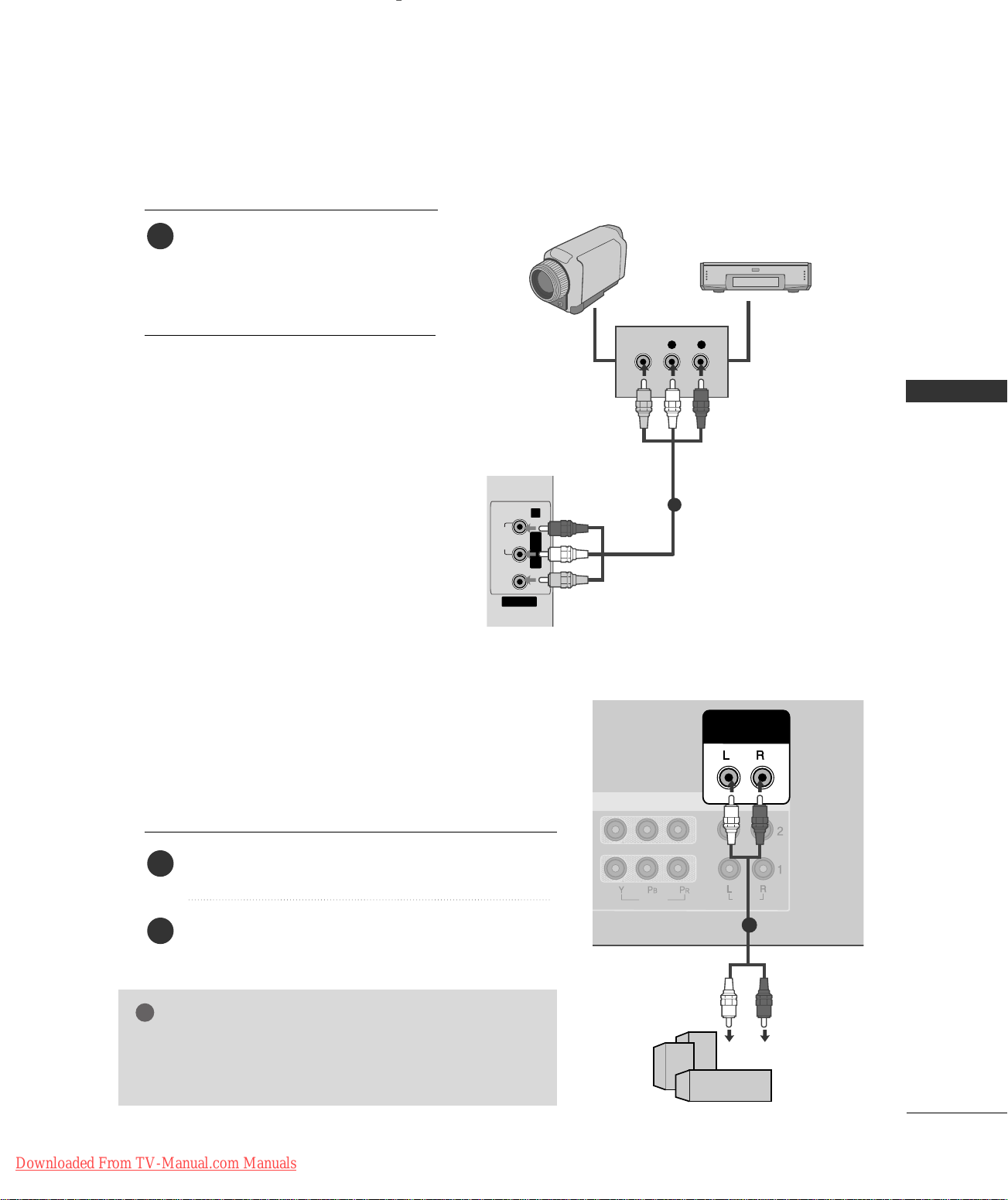
EXTERNAL EQUIPMENT CONNECTIONS
VIDEO
AV IN 2
L/MONO R
AUDIO
L R
VIDEO
VIDEO
AUDIO
AUDIO OUT
VARIABLE
COMPONENT IN
!
1. How to connect
Camcorder
Connect the
1
between TV and external equipment.
Match the jack colors
(
Video = yellow, Audio Left = white, and
Audio Right = red
2. How to use
AAUUDDIIOO/VVIIDDEEOO
.
)
jacks
Video Game Set
■
■
■
AAVV11
Select
IINNPPUUTT
If connected to
AAVV22
input source with using the
button on the remote control.
AAVV IINN22
input, select
input source.
Operate the corresponding external
equipment.
EXTERNAL STEREO
Use to connected either an external amplifier, or add a subwoofer to your surround sound system.
1. How to connect
Connect the input jack of the stereos amplifier to the
1
VVAA RRIIAABBLLEE AAUUDDIIOO OOUUTT
jacks on the set.
CONNECTIONS & SETUP
1
Set up your speakers through your analog stereo
2
amplifier, according to the instructions provided with
the amplifier.
NOTE
When connecting with external audio equipments, such as
GG
amplifiers or speakers, please turn the TV speakers off.
pp..4477
GG
Downloaded From TV-Manual.com Manuals
(
)
11
15
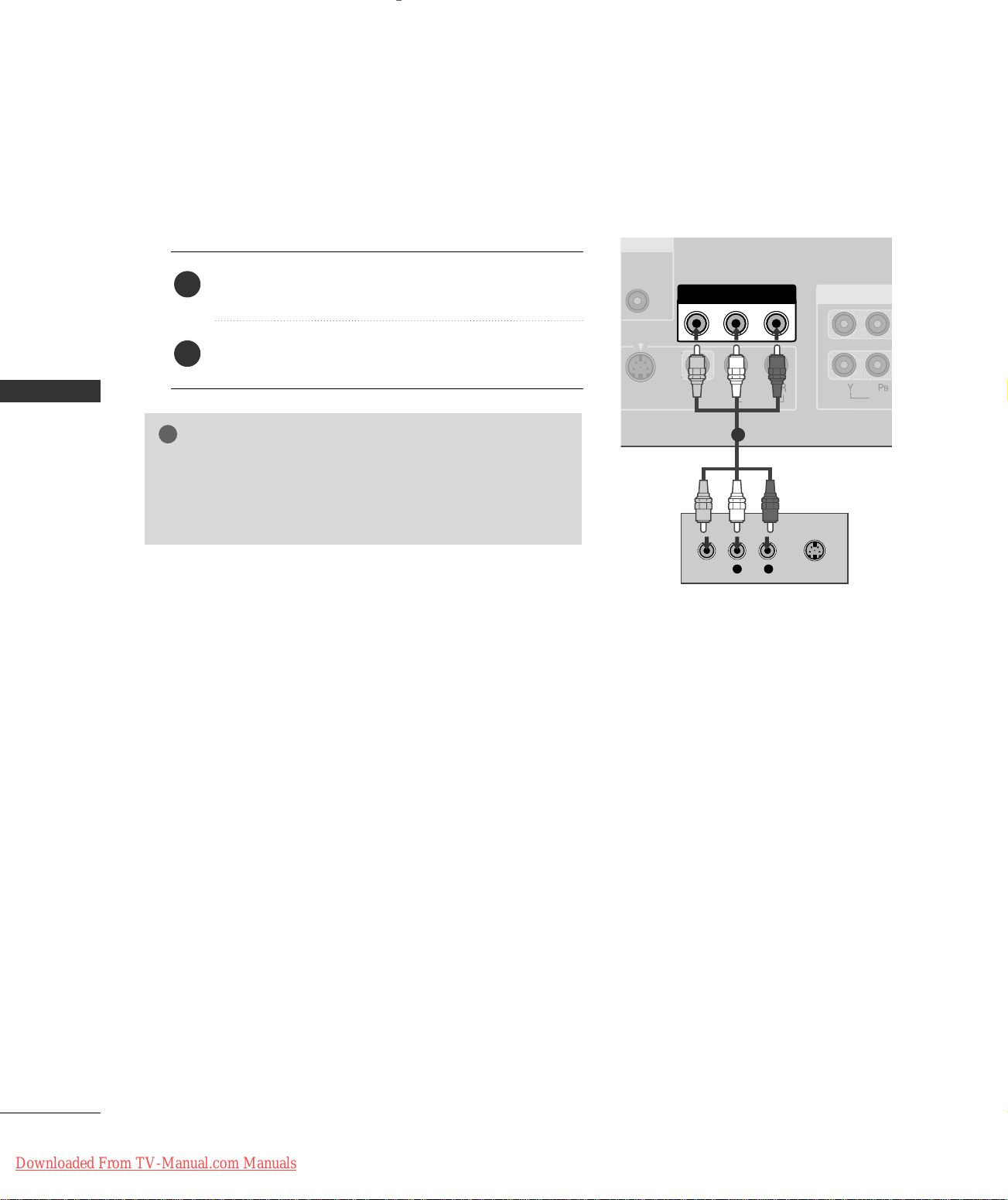
AV OUT SETUP
MONO
( )
AUDIO
VIDEO
S-VIDEO
AV OUT
VIDEO
AUDIO
COMPONE
L R
S-VIDEOVIDEO
!
The TV has a special signal output capability which allows you to hook up the second TV or monitor.
1. How to connect
CONNECTIONS & SETUP
Connect the second TV or monitor to the TV’s
1
jacks.
See the Operating Manual of the second TV or monitor
2
for further details regarding that device’s input settings.
NOTE
Component, RGB, HDMI input sources cannot be used for
GG
AV out.
We recommend to use the AV OUT jacks for VCR recording.
GG
AAVV OOUUTT
1
16
Downloaded From TV-Manual.com Manuals
)
IO
AUDIO OUT
VARIABLE
COMPONENT IN
VIDEO
AUDIO
Y L RPB PR
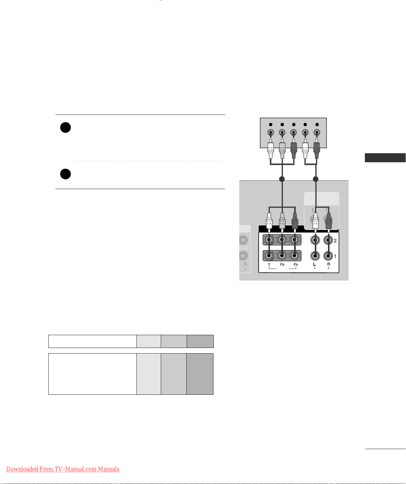
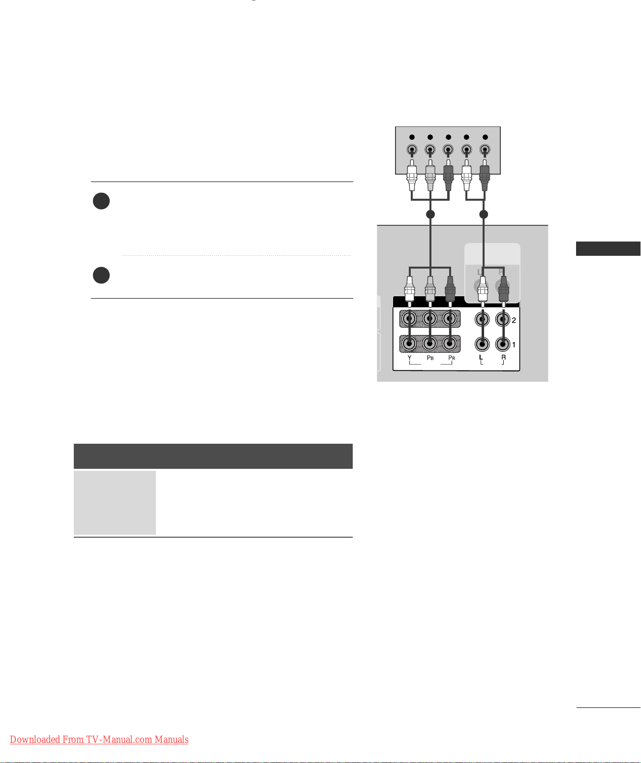
DVD SETUP
When connecting with a component cable
1. How to connect
)
Connect the video outputs (Y, PB
1
CCOOMMPPOONNEENNTT IINN VVIIDDEEOO11
the
Match the jack colors
(
Y = green, P
B = blue, and PR = red
of the DVD to
, PR
jacks on the set.
)
.
Connect the audio outputs of the DVD to the
2
CCOOMMPPOONNEENNTT IINN AAUUDDIIOO11
jacks on the set.
2. How to use
■
Turn on the DVD player, insert a DVD.
■
■
■
Component Input ports
To get better picture quality, connect a DVD player to the component input ports as shown below.
Component ports on the TV
CCOOMMPPOO NNEENNTT 11
Select
IINNPPUUTT
button on the remote control.
If connected to
PPOONNEENNTT 22
input source.
CCOOMMPPOONNEENNTT IINN 22
input source with using the
input, select
CCOO MM--
Refer to the DVD player's manual for operating instructions.
YPB PR
CONNECTIONS & SETUP
1 2
Video output ports
on DVD player
Downloaded From TV-Manual.com Manuals
Y
Y
Y
Y
PB
B-Y
Cb
Pb
P
R-Y
Cr
Pr
R
17
CONNECTIONS & SETUP
VIDEO
AUDIO
&
SERVICE)
VIDEO
AV IN 1
RGB IN
AV OUT
VIDEO
AUDIO
RGB
AUDIO
(RGB/DVI)
MONO
( )
AUDIO
S-VIDEO
L R
S-VIDEOVIDEO
OUTPUT
SWITCH
ANT IN
ANT OUT
VIDEO
AUDIO
VIDEO
AUDIO
RS-232C IN
(CONTROL & SERVICE)
RGB IN
VIDEO
AUDIO
HDMI IN
2
1 (DVI)
REMOTE
CONTROL
IN
RGB
(PC/DTV)
HDMI-DVD OUTPUT
!
CONNECTIONS & SETUP
When connecting with an S-Video cable
1. How to connect
Connect the S-VIDEO output of the DVD to the
1
SS --VVIIDDEEOO
Connect the audio outputs of the DVD to the
2
input jacks on the set.
input on the set.
AAUUDDIIOO
2. How to use
■
Turn on the DVD player, insert a DVD.
■
Select
AAVV11
input source with using the
IINNPPUUTT
button on
the remote control.
■
If connected to
■
Refer to the DVD player's manual for operating instructions.
AAVV IINN22
, select
AAVV22
input source.
When connecting HDMI cable
1
2
1. How to connect
Connect the HDMI output of the DVD to the
1
HHDDMMII II NN 11((DDVVII))
No separated audio connection is necessary.
2
2. How to use
■
■
HHDDMMII11//DDVVII orHHDDMMII22
Select
IINNPPUUTT
the
Refer to the DVD player's manual for operating instructions.
button on the remote control.
NOTE
If the DVD supports Auto HDMI function, the DVD output
GG
resolution will be automatically set to 1280x720p.
If the DVD does not support Auto HDMI, you need to set
GG
the output resolution appropriately.
To get the best picture quality, adjust the output resolution
of the DVD to 1280x720p.
or 22jack on the set.
input source with using
1
18
Downloaded From TV-Manual.com Manuals
HDSTB SETUP
AUDIO OUT
VARIABLE
COMPONENT IN
VIDEO
AUDIO
Y L RPB PR
When connecting with a component cable
1. How to connect
)
Connect the video outputs (Y, P
1
top box to the
CCOOMMPPOONNEENNTT IINN VVIIDDEEOO 11
on the set. Match the jack colors
(Y = green, P
B = blue, and PR = red).
of the digital set
B, PR
jacks
1 2
Connect the audio output of the digital set-top box to
2
CCOOMMPPOONNEENNTT IINN AAUUDDIIOO 11
the
2. How to use
■
Turn on the digital set-top box.
(
Refer to the owner’s manual for the digital set-top box.
■
■
CCOOMMPPOO NNEENNTT 11
Select
IINNPPUUTT
If connected to
button on the remote control.
CCOOMMPPOONNEENNTT IINN22
CCOOMMPPOO NNEENNTT 22
Signal
Component 1/2
480i
480p
720p
10 8 0 i
input source with using the
input, select
input source.
RGB-DTV, HDMI2
Yes
Yes
Yes
Yes
CONNECTIONS & SETUP
jacks on the set.
)
HDMI1/DVI,
No
Yes
Yes
Yes
Downloaded From TV-Manual.com Manuals
19
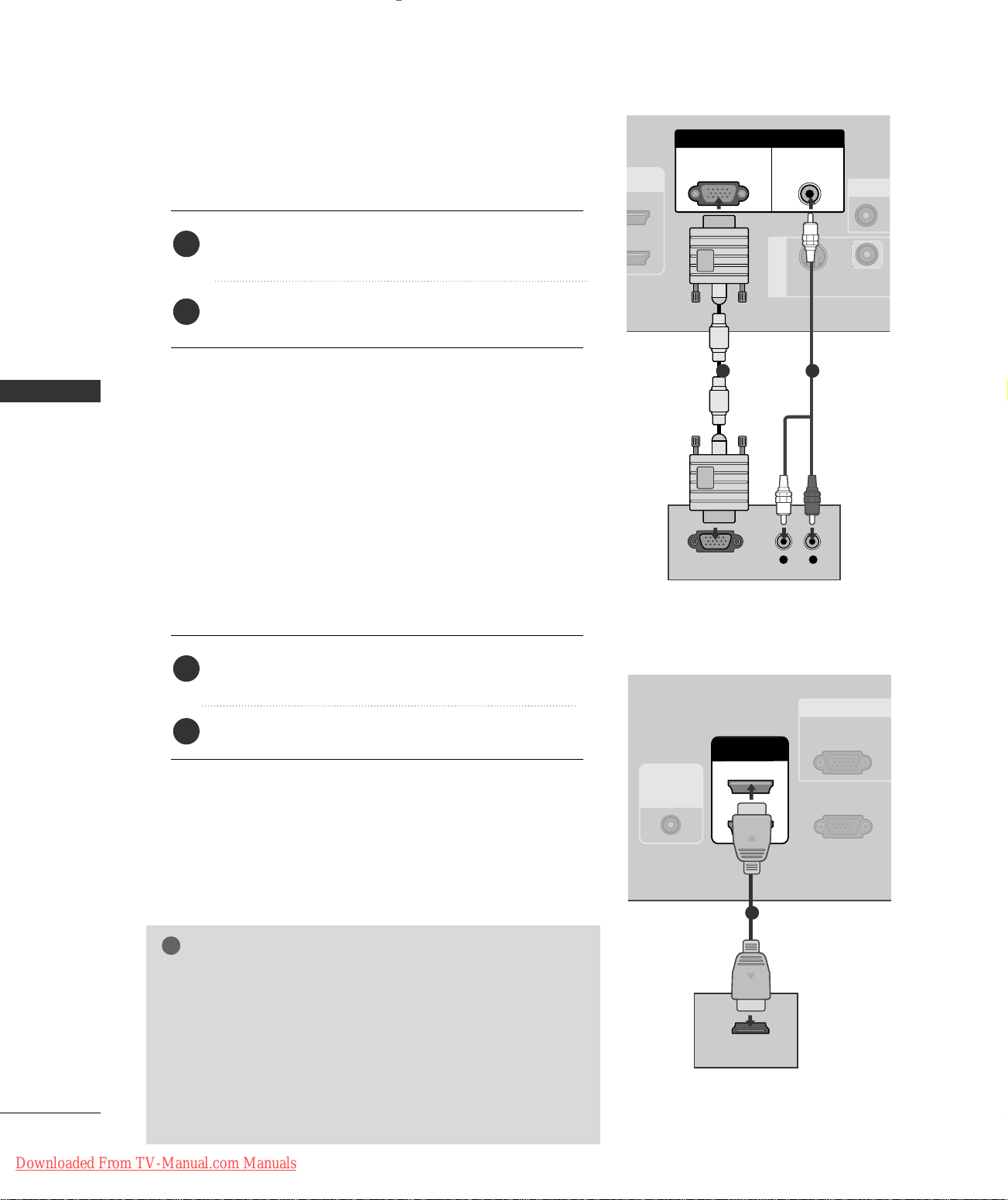
CONNECTIONS & SETUP
RS-232C IN
(CONTROL & SERVICE)
VIDEO
S-VIDEO
AV IN 1
RGB IN
A
VIDEO
AUDIO
RGB
(PC/DTV)
AUDIO
(RGB/DVI)
L R
RGB OUTPUT
VIDEO
AUDIO
RS-232C IN
(CONTROL & SERVICE)
RGB I
VIDEO
AUDIO
HDMI IN
2
1 (DVI)
REMOTE
CONTROL
IN
RGB
(PC/DTV)
HDMI-DVD OUTPUT
!
When connecting with a D-sub 15 pin cable
1. How to connect
Connect the RGB output of the digital set-top box to
1
RRGG BB ((PPCC // DD TT VV
the
Connect the audio outputs of the set-top box to the
2
AAUUDDIIOO ((RRGGBB// DDVVII
))
jack on the set.
))
jack on the set.
CONNECTIONS & SETUP
2. How to use
■
Turn on the digital set-top box.
(
Refer to the owner’s manual for the digital set-top box.
■
Select
RRGGBB--DDTTVV
input source with using the
button on the remote control.
When connecting with a HDMI cable
1. How to connect
1
2
2. How to use
■
Turn on the digital set-top box.
(
Refer to the owner’s manual for the digital set-top box.
■
Select
the
NOTE
Connect the digital set-top box to
22
or
jack on the set.
No separated audio connection is necessary.
HHDDMMII11//DDVVII
IINNPPUUTT
button on the remote control.
HHDDMM II22
or
HHDDMMII IINN 11((DDVVII))
input source with using
IINNPPUUTT
)
)
1
1
2
If the digital set-top box supports Auto HDMI function, the
GG
output resolution of the source device will be automatically
set to 1280x720p.
If the digital set-top box player does not support Auto HDMI,
GG
you need to set the output resolution appropriately.
To get the best picture quality, adjust the output resolution of
20
Downloaded From TV-Manual.com Manuals
the source device to 1280x720p.
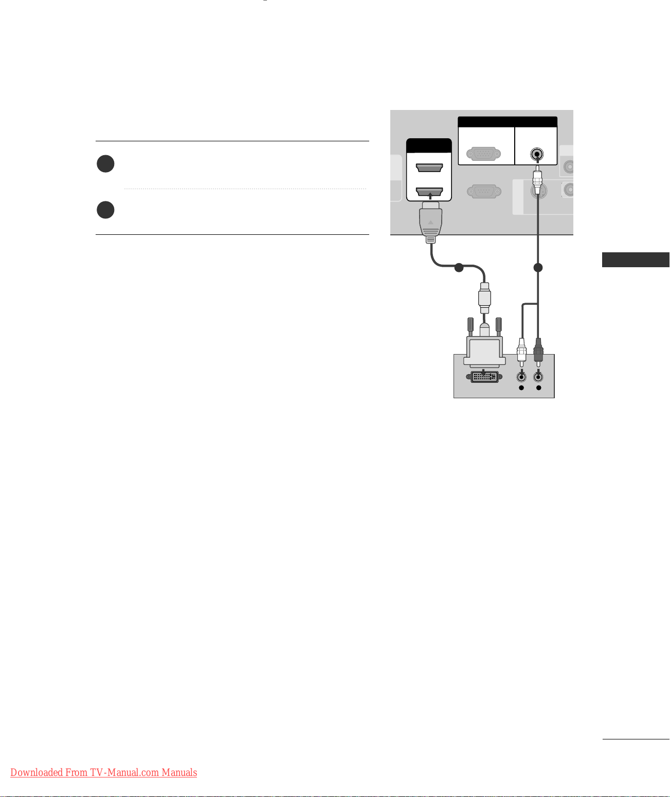
When connecting with a HDMI to DVI cable
L R
DVI-DTV OUTPUT
VIDEO
AUDIO
RS-232C IN
(CONTROL & SERVICE)
VIDE
S-VIDEO
AV IN 1
RGB IN
VIDEO
AUDIO
RGB
(PC/DTV)
AUDIO
(RGB/DVI)
HDMI IN
2
1 (DVI)
1. How to connect
Connect the DVI output of the digital set-top box to the
1
HHDDMMII IINN 11((DDVVII))
Connect the audio output of the digital set-top box to
2
AAUUDDIIOO((RRGGBB// DDVVII
the
jack on the set.
))
jack on the set.
2. How to use
■
Turn on the digital set-top box. (Refer to the owner’s manual for the digital set-top box.
■
HHDDMMII11//DDVVII
Select
button on the remote control.
)
input source with using the
IINNPPUUTT
1 2
CONNECTIONS & SETUP
Downloaded From TV-Manual.com Manuals
21
CONNECTIONS & SETUP
!
RS-232C IN
(CONTROL & SERVICE)
VIDEO
S-VIDEO
AV IN 1
RGB IN
AV O
VIDEO
AUDIO
RGB
(PC/DTV)
AUDIO
(RGB/DVI)
RGB OUTPUT
AUDIO
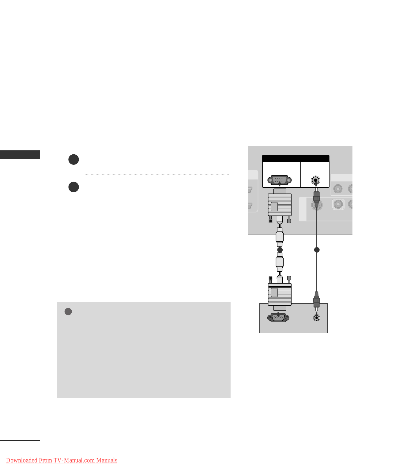
PC SETUP
This TV provides Plug and Play capability, meaning that the PC adjusts automatically to the TV's settings.
When connecting with a D-sub 15 pin cable
1. How to connect
CONNECTIONS & SETUP
Connect the RGB output of the PC to the
1
((
PPCC // DD TT VV
Connect the PC audio output to the
2
((
RRGGBB// DDVVII
))
jack on the set.
))
jack on the set.
AAUUDDIIOO
2. How to use
■
Turn on the PC and the set.
■
Check the image on your TV. There may be noise associ-
GG
ated with the resolution, vertical pattern, contrast or
brightness in PC mode. If noise is present, change the PC
output to another resolution, change the refresh rate to
another rate or adjust the brightness and contrast on the
VIDEO menu until the picture is clear. If the refresh rate
of the PC graphic card can not be changed, change the
PC graphic card or consult the manufacturer of the PC
graphic card.
RRGGBB--PPCC
Select
input source with using the
on the remote control.
NOTE
RR GG BB
IINNPPUUTT
button
1 2
22
Downloaded From TV-Manual.com Manuals
 Loading...