

LG 42LB9RTA User manual [pt]

Please read this manual carefully and completely
before operating your set. Retain it for future reference.
Record model number and serial number of the set.
See the label attached on the back cover and quote
this information to your dealer when you require service.
LCD TV MODELS
3322LLBB99RRTT
3322LLBB99RRTTBB
3322LLBB99RRTTEE
4422LLBB99RRTT
4422LLBB99RRTTBB
4422LLBB99RRTTEE
PLASMA TV MODELS
4422PPBB44RRTT
4422PPBB44RRTTHH
5500PPBB44RRTT
5500PPBB44RRTTHH
LCD TV
PLASMA TV
OWNER’S MANUAL
MFL36546204en_1 12/31/07 2:01 PM Page 1

MFL36546204en_1 12/31/07 2:01 PM Page 2

1
IMPORTANT SAFETY INSTRUCTIONS
Important safety instructions shall be provided with each apparatus. This information shall be given in a separate booklet or sheet, or be located before any operating instructions in an instruction for installation for
use and supplied with the apparatus.
This information shall be given in a language acceptable to the country where the apparatus is intended to
be used.
The important safety instructions shall be entitled “Important Safety Instructions”. The following safety
instructions shall be included where applicable, and, when used, shall be verbatim as follows. Additional safety information may be included by adding statements after the end of the following safety instruction list. At
the manufacturer’s option, a picture or drawing that illustrates the intent of a specific safety instruction may
be placed immediately adjacent to that safety instruction :
Read these instructions.
Keep these instructions.
Heed all warnings.
Follow all instructions.
Do not use this apparatus near water.
Clean only with dry cloth.
Do not block any ventilation openings. Install in
accordance with the manufacturer’s instructions.
Do not install near any heat sources such as
radiators, heat registers, stoves, or other apparatus (including amplifiers)that produce heat.
Do not defeat the safety purpose of the
polarized or grounding-type plug. A polarized
plug has two blades with one wider than the
other. A grounding type plug has two blades
and a third grounding prong, The wide blade
or the third prong are provided for your safety. If the provided plug does not fit into your
outlet, consult an electrician for replacement
of the obsolete outlet.
WARNING
MFL36546204en_1 12/31/07 2:02 PM Page 1
2
IMPORTANT SAFETY INSTRUCTIONS
Protect the power cord from being walked on
or pinched particularly at plugs, convenience
receptacles, and the point where they exit
from the apparatus.
Only use attachments/accessories specified
by the manufacturer.
Unplug this apparatus when unused for long
periods of time.
Use only with the cart, stand, tripod, bracket,
or table specified by the manufacturer, or sold
with the apparatus. When a cart is used, use
caution when moving the cart/apparatus
combination to avoid injury from tip-over.
Never touch this apparatus or antenna during
a thunder or lighting storm.
Do not allow a impact shock or any objects to
fall into the product, and do not drop onto the
screen with something. (You may be injured or
the product can be damaged.)
Refer all servicing to qualified service personnel. Servicing is required when the apparatus
has been damaged in any way, such as powersupply cord or plug is damaged, liquid has
been spilled or objects have fallen into the
apparatus, the apparatus has exposed to rain
or moisture, does not operate normally, or has
been dropped.
WARNING
MFL36546204en_1 12/31/07 2:02 PM Page 2
3
CAUTION concerning the Power Cord :
Most appliances recommend they be placed
upon a dedicated circuit; that is, a single outlet circuit which powers only that appliance
and has no additional outlets or branch circuits. Check the specification page of this
owner's manual to be certain.
Do not overload wall outlets. Overloaded wall
outlets, loose or damaged wall outlets, extension cords, frayed power cords, or damaged
or cracked wire insulation are dangerous. Any
of these conditions could result in electric
shock or fire. Periodically examine the cord of
your appliance, and if its appearance indicates damage or deterioration, unplug it, discontinue use of the appliance, and have the
cord replaced with an exact replacement part
by an authorized servicer. Protect the power
cord from physical or mechanical abuse, such
as being twisted, kinked, pinched, closed in a
door, or walked upon. Pay particular attention
to plugs, wall outlets, and the point where
the cord exits the appliance.
Outdoor Use Marking :
WARNING - To Reduce The Risk Of Fire Or
Electric Shock, Do Not Expose This Appliance
To Rain Or Moisture
Wet Location Marking : Apparatus shall not
be exposed to dripping or splashing and no
objects filled with liquids, such as vases, shall
be placed on or over apparatus.
GROUNDING
Ensure that you connect the earth ground
wire to prevent possible electric shock. If
grounding methods are not possible, have a
qualified electrician install a separate circuit
breaker.
Do not try to ground the unit by connecting
it to telephone wires, lightening rods, or gas
pipes.
DISCONNECTING DEVICE FROM MAINS
Main plug is the disconnecting device. The
plug must remain readily operable.
Owner Manual
Power Supply
Short-circuit Breaker
Owner Manual
Owner Manual
MFL36546204en_1 12/31/07 2:02 PM Page 3
4
CONTENTS
Remote Control Key Functions.................................38
Turning on the TV....................................................... 40
Channel Selection....................................................... 40
Volume Adjustment......................................................40
On Screen Menus Selection and Adjustment.......41
Auto Channel Tuning.................................................. 42
Manual tuning: Adding/Deleting Channels
.......... 43
Fine Tuning Adjustment..............................................44
Booster............................................................................45
Favorite Channels Setup............................................ 46
Input Source Selection....................................................... 47
Key lock...........................................................................48
................................................................. 49
WATCHING TV / SETUP CONTROL
WARNING . . . . . . . . . . . . . . . . . . . . . . . . . . . . . . . . . . . . . . . . . . . . . . . . . .1
FEATURES OF THIS TV
. . . . . . . . . . . . . . . . . . . . . . . . . . . . .6
ACCESSORIES
. . . . . . . . . . . . . . . . . . . . . . . . . . . . . . . . . . . . . . . . .7
PREPARATION
Time Machine Home Menu..........................................8
Front Panel Controls..................................................... 9
Back Panel Information............................................... 11
Stand Installation......................................................... 13
Attaching the TV to a Desk........................................13
Attaching the TV to a Wall .........................................14
Back Cover for Wire Arrangement .......................... 15
Desktop Pedestal Installation................................... 17
Wall Mount: Horizontal installation ........................ 17
Antenna Connection................................................... 18
EXTERNAL EQUIPMENT SETUP
HD Receiver Setup.......................................................19
DVD Setup.................................................................... 22
VCR Setup..................................................................... 25
Other A/V Source Setup.......................................... 28
AV Output Setup........................................................ 29
External Stereo Setup................................................ 29
USB in Setup .................................................................30
PC Setup........................................................................31
- Screen Setup for PC Mode................................34
PREPARATION
TIME MACHINE
Time Control (Pause & Replay of Live TV).......... 52
Format hard disk ...........................................................55
Instant Recording .........................................................56
Manual Record..............................................................58
Schedule List..................................................................59
Record Quality ..............................................................59
To use the USB device................................................60
Recorded TV Program List.........................................62
USB Backup ..................................................................65
Photo List........................................................................68
Music List........................................................................72
Movie List........................................................................75
Subtitle............................................................................77
DivX Registration Code..............................................78
MFL36546204en_1 12/31/07 2:02 PM Page 4
5
PICTURE CONTROL
Watching PIP(Picture-in-Picture) .............................79
Picture Size (Aspect Ratio)Control .........................81
Preset Picture Settings
- Picture Mode-Preset............................................83
-
Auto Color Temperature Control(Warm/Medium/Cool)
.84
Manual Picture Adjustment
- Picture Mode-User option.................................85
- Color Temperature - User option....................86
-
Picture Improvement Technology
...................87
Demo .................................................................88
Advanced - Cinema......................................................89
Advanced - Black(Darkness) Level...........................90
Picture Reset..................................................................91
Image Sticking Minimization(ISM) Method ..........92
Low-Power Picture Mode............................................93
SOUND & LANGUAGE CONTROL
Auto Volume Leveler....................................................94
Preset Sound Settings - Sound Mode ....................95
Sound Setting Adjustment - User Mode...............96
Balance ............................................................................97
TV Speakers On/Off Setup.......................................98
On-Screen Menu Language Selection
...................... 99
PICTURE CONTROL
APPENDIX
Troubleshooting..........................................................105
Maintenance ...............................................................107
Product Specifications..............................................108
Programming the Remote Control ........................110
IR Codes ........................................................................112
External Control Device Setup................................114
TIME SETTING
Clock Setup.................................................................100
Auto On/Off Timer Setting......................................101
Sleep Timer Setting ...................................................102
Auto Shut-off Setting................................................103
CAPTION/TEXT
Closed Captions .......................................................104
MFL36546204en_1 12/31/07 2:02 PM Page 5

What is a Plasma TV ?
Using plasma is the best way to achieve flat panel
displays with excellent image quality and large
screen sizes that are easily viewable. The Plasma TV
can be thought of as a descendant of the neon
lamp and or a series of fluorescent lamps.
How does it work?
Plasma TV is an array of cells, known as pixels, which
are comprised of three sub-pixels, corresponding to
the colors red, green, and blue. Gas in a plasma
state is used to react with phosphors in each subpixel to produce colored light (red, green, or blue).
These phosphors are the same types used in
Cathode Ray Tube (CRT) devices such as televisions
and common computer monitors.
Plasma TV offers a rich, dynamic display because
each sub-pixel is individually controlled by advanced
electronics to produce over 16 million different colors. This means that you get perfect images that are
easily viewable in a display that is fewer than five
inches thick.
160° - Wide angle range of vision
Your flat panel plasma screen offers an exceptionally
broad viewing angle of over 160 degrees. This
means that the display is clear and visible to viewers
anywhere in the room.
Wide Screen
The wide screen offers a theater-like experience in
your own home.
Multimedia
Connect your plasma display to a PC and use it for
conferencing, games, and Internet browsing. The
Picture-in-Picture feature allows you to view your PC
and video images simultaneously.
Versatile
The light weight and thin size makes it easy to
install your plasma display in a variety of locations
where conventional TVs do not fit.
The Plasma TV Manufacturing Process: a few
minute colored dots may be present on the
Plasma TV screen
The Plasma TV is composed of 0.9 to 2.2 million
cells. A few cell defects will normally occur in the
Plasma TV manufacturing process. Several tiny,
minute colored dots visible on the screen should be
acceptable. This also occurs in other Plasma TV
manufacturers' products. The tiny dots appearing
does not mean that this Plasma TV is defective.
Thus a few cell defects are not sufficient cause for
the Plasma TV to be exchanged or returned. Our
production technology minimizes these cell defects
during the manufacture and operation of this product.
FOR LCD TV
If the TV feels cold to the touch, there may be a
small “flicker” when it is turned on. This is normal,
there is nothing wrong with TV.
Some minute dot defects may be visible on the
screen, appearing as tiny red, green, or blue spots.
However, they have no adverse effect on the monitor's performance.
Avoid touching the LCD screen or holding your finger(s)
against it for long periods of time. Doing so may produce some temporary distortion effects on the screen.
OOnn DDiissppoossaall
a. The fluorescent lamp used in this product con-
tains a small amount of mercury.
b. Do not dispose of this product with general
household waste.
c. Disposal of this product must be carried out in
accordance to the regulations of your local
authority.
FEATURES OF THIS TV
6
MFL36546204en_1 12/31/07 2:02 PM Page 6
7
PREPARATION
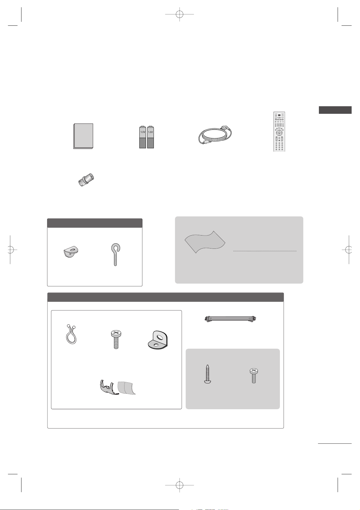
ACCESSORIES
Ensure that the following accessories are included with your TV. If an accessory is missing, please contact the
dealer where you purchased the product.
Batteries
Power Cord
Twister Holder
Arrange the wires
with the twister
holder.
LLCCDD TTVV mmooddeellss
Polishing Cloth
Polish the screen with the cloth
*Slightly wipe stained spot on the
exterior only with the cleansing
cloths for the product exterior if
there is stain or fingerprint on surface
of the exterior.
Do not wipe roughly when removing
stain. Please be cautious of that
excessive power may cause scratch
or discoloration.
Cable Management
PPllaassmmaa TTVV mmooddeellss
2-Wall brackets
2-eye-bolts
Owner’s Manual
3322”” oonnllyy
1-bolts for stand fixing
Refer to p. 13
4-bolts for stand assembly
Refer to p. 13
ENTER
INPUT MODE
TVTV
DVD
RATIO
MENU
VOLCH
PIP
EXIT
TIME
CONTROL
TIME
CONTROL
LIVE TV
MTS
TIME
MACHINE
VCR
PIP CH- PIP CH+
PIP INPUT
POWER
123
456
789
0
FAV/
MARK
CAPTION
SIMPLINK
INPUT
MUTE
SWAP
SLEEP
REVIEW
CH EDIT
BRIGHT
Remote Control
2- TV Bracket Bolts 2- TV Brackets,
2- Wall Brackets
* This feature is not available for all models.
* This feature is not available for all models.
RF Adapter
(Some models)
You must connect it to the antenna wire after fixing in Antenna Input.
This adapter is only supplied in Argentina.
3- Ring
MFL36546204en_1 12/31/07 2:02 PM Page 7
Owner's Manual
8
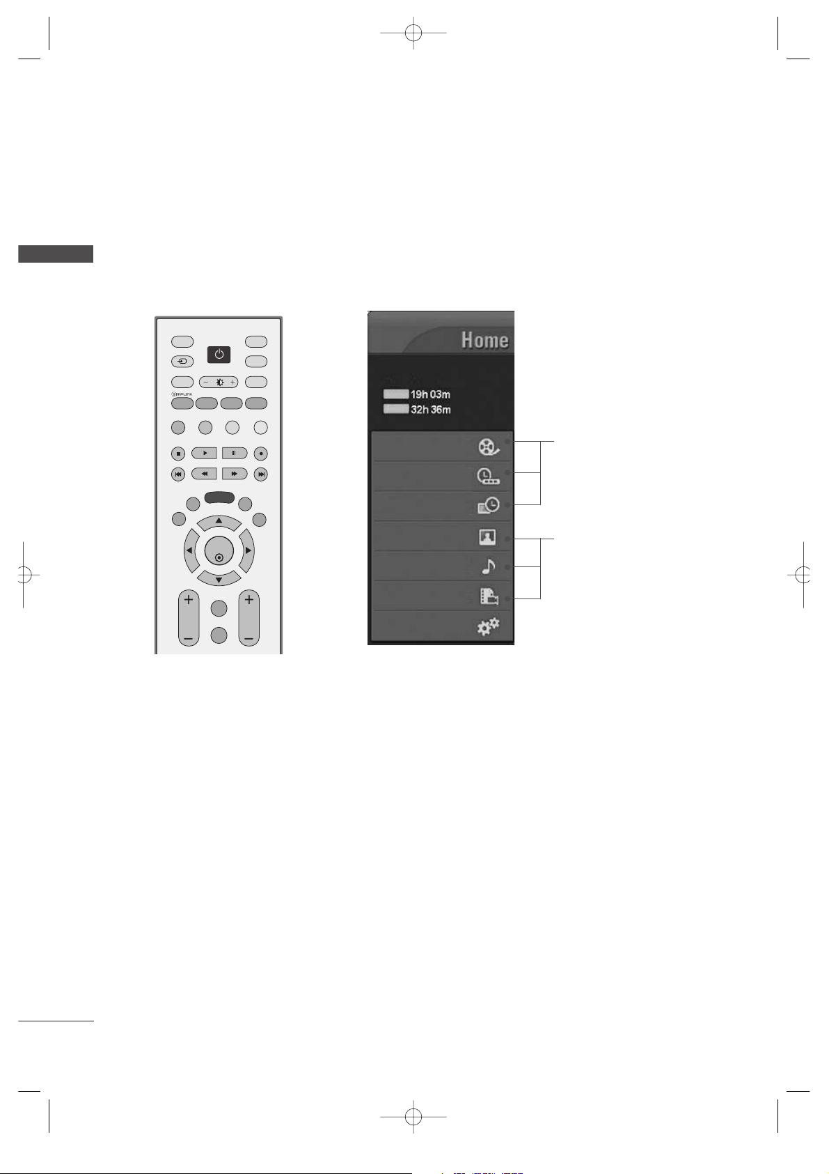
TIME MACHINE HOME MENU
PREPARATION
PREPARATION
This menu is a contents guide.
In Home Menu, you enter the Recorded list of TIME MACHINE, Manual Record of TIME MACHINE, Schedule
List, Photo List, Music List, Movie List or TV Menu.
ENTER
INPUT MODE
TVTV
DVD
RATIO
MENU
VOL
CH
PIP
EXIT
TIME
CONTROL
TIME
CONTROL
LIVE TV
MTS
TIME
MACHINE
VCR
PIP CH- PIP CH+
PIP INPUT
POWER
FAV/
MARK
CAPTION
SIMPLINK
INPUT
MUTE
SWAP
CH EDIT
BRIGHT
G
pp..5522
G
pp..6688~7766
Recorded TV
Manual Record
Schedule List
Photo List
Music List
Movie List
TV Menu
HIGH
NORMAL
TIME MACHINE
TIME MACHINE
Free Space
MFL36546204en_1 12/31/07 2:02 PM Page 8

9
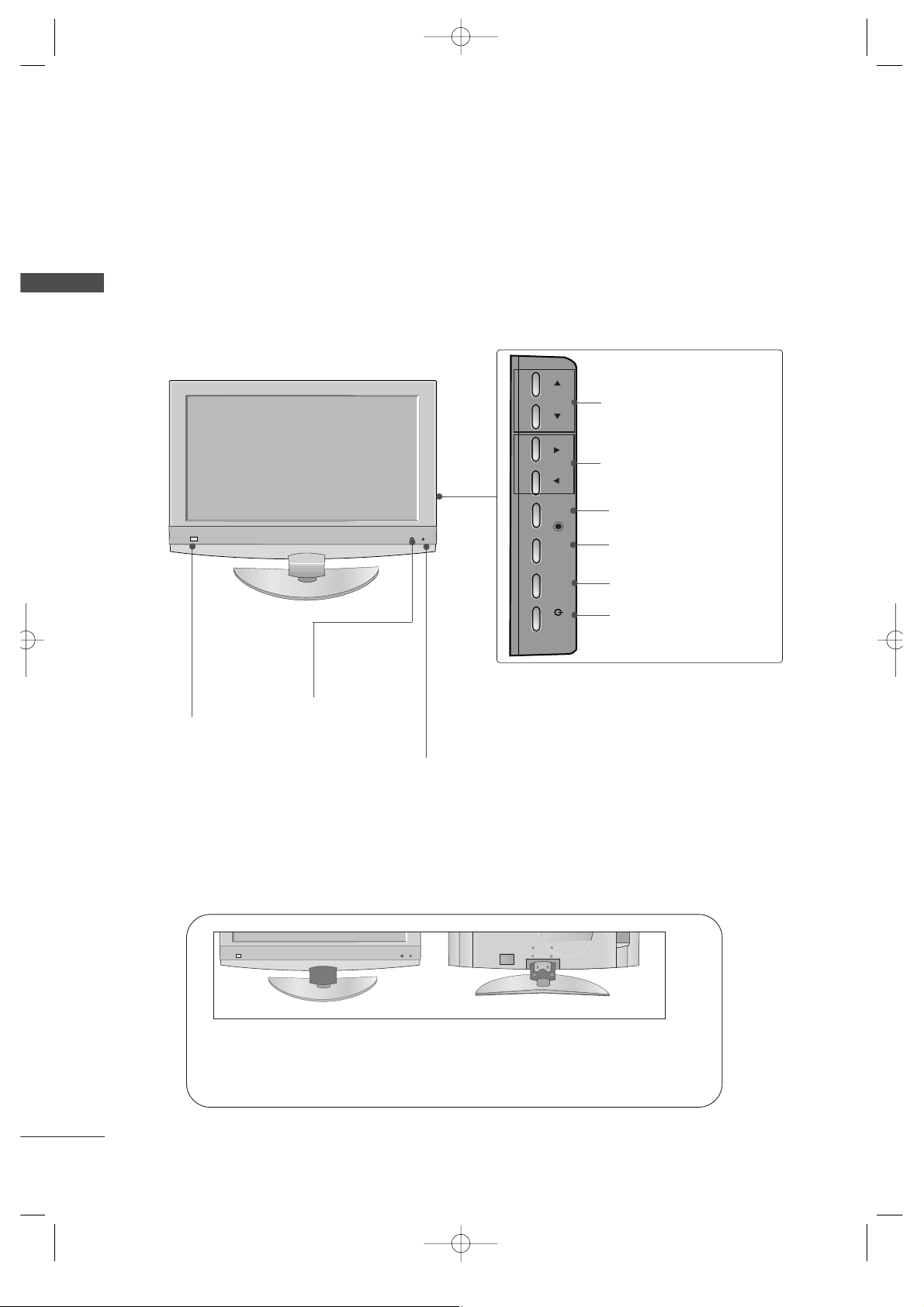
FRONT PANEL CONTROLS
PREPARATION
■
This is a simplified representation of the front panel. Here shown may be somewhat different from your TV.
■
If your product has a protection film attached, remove the film and then wipe the product with a polishing
cloth.
CH
VOL
ENTER
MENU
INPUT
CHANNEL
Buttons
VOLUME
Buttons
MENU
Button
ENTER
Button
INPUT
Button
POWER
Button
Plasma TV Models
Remote Control Sensor
Power/Standby Indicator
• illuminates red in standby mode.
• illuminates green when the set is switched on.
• illuminates orange when the set is switched off
during recording.
MFL36546204en_1 12/31/07 2:02 PM Page 9
10
PREPARATION
PREPARATION
LCD TV Models
CH
VOL
CH
VOL
ENTER
MENU
INPUT
/I
CH
VOL
CHANNEL
(
EE,DD
) Buttons
VOLUME
(
FF,GG
) Buttons
ENTER Button
MENU Button
INPUT Button
POWER Button
Remote Control
Sensor
Intelligent Eye
Adjusts picture
according to the
surrounding
conditions.
Power/Standby Indicator
• illuminates red in standby mode.
• illuminates green when the set is switched on.
• illuminates orange when the set is switched off during
recording.
<<OOnnllyy 3322//4422LLBB99RRTTEE>>
Pull stand ring to the front to disassemble if easily and same way in the backside.
Assemble the ring of the color you desired in stand.
MFL36546204en_1 12/31/07 2:02 PM Page 10
HDMI IN HDMI/DVI IN
1
2
2
1
AUDIO
(RGB/DVI)
RGB
(PC)
COMPONENT IN
AUDIO
VIDEO
AV IN 1 AV OUT
L/L
/M
O
N
O
M
O
N
O
R
AUDIOAUDIO
V
ID
E
O
V
ID
E
O
ANTENNA
IN
USB
AV IN 2
L/ MONO
R
AUDIO
VIDEO
S-VIDEO
11
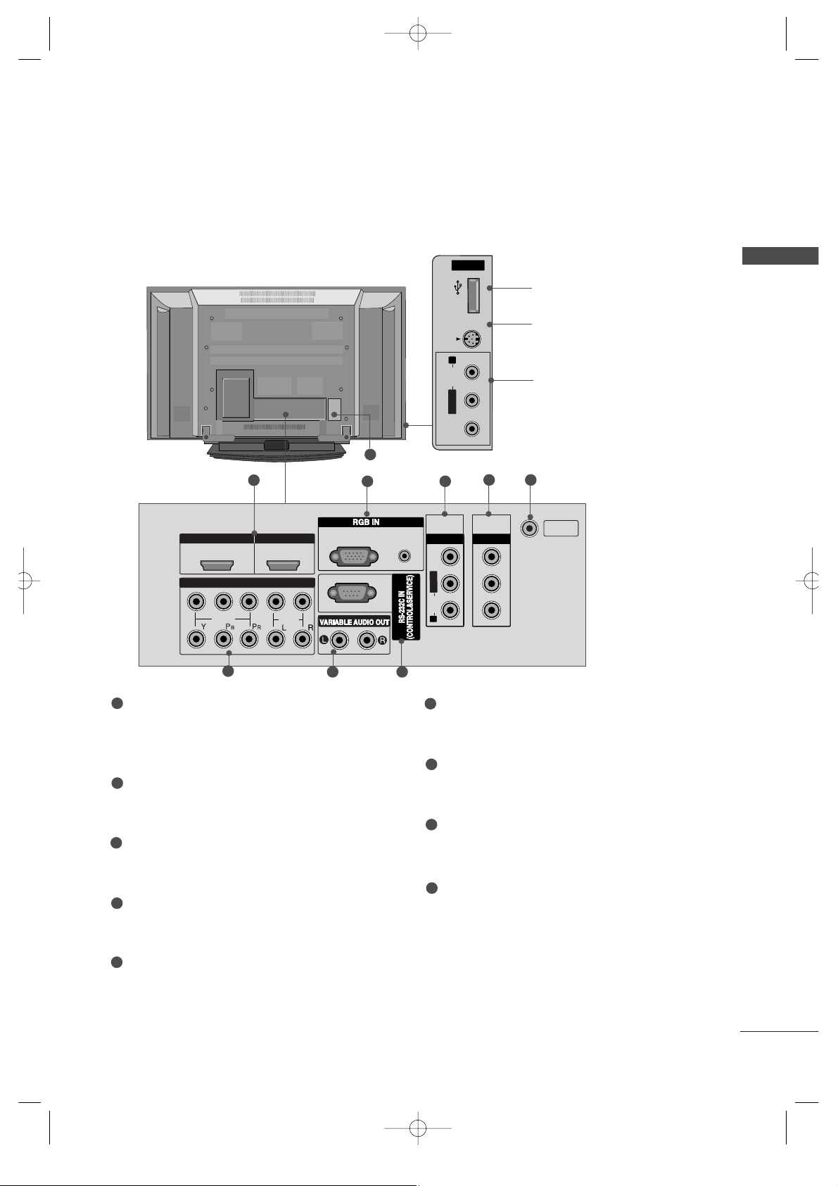
BACK PANEL INFORMATION
PREPARATION
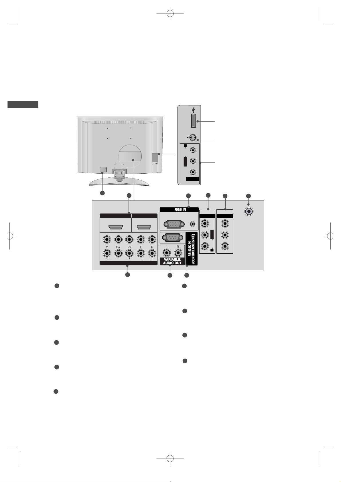
■
This is a simplified representation of the back panel. Here shown may be somewhat different from your TV.
Plasma TV Models
USB
AV IN 2
L/MONO
R
AUDIO
S-VIDEO
1
4
7 8
6
USB Input
S-Video Input
Connect S-Video out from an
S-VIDEO device.
Audio/Video Input
Connect audio/video output
from an external device to
these jacks.
USBUSB
AV IN 2
L/MONO
R
AUDIOAUDIO
VIDEOVIDEO
S-VIDEO
9
5
2 3
HDMI/DVI1, HDMI2 Input
Connect a HDMI signal to HDMI IN.
Or DVI(VIDEO)signal to HDMI/DVI port with DVI
to HDMI cable.
RGB/Audio Input
Connect the monitor output from a PC to the
appropriate input port.
Audio/Video Input (AV IN 1)
Connect audio/video output from an external
device to these jacks.
AV Output
Connect second TV or monitor to the AV OUT
socket on the set.
Antenna Input
Connect over-the-air signals to this jack.
Component Input 1/2
Connect a component video/audio device to
these jacks.
Variable Audio Output
Connect an external amplifier or add a subwoofer
to your surround sound system.
RS-232C Input
(CONTROL&SERVICE)Port
Connect the serial port of the control devices
to the RS-232C jack.
Power Cord Socket
This TV operates on an AC power. The voltage is
indicated on the Specifications page. Never
attempt to operate the TV on DC power.
1
2
3
4
5
6
7
8
9
MFL36546204en_1 12/31/07 2:02 PM Page 11
12
■
This is the back panel of model 32LB9RT*.
PREPARATION
PREPARATION
AV IN 2
L/MONO
R
AUDIO
VIDEO
USB IN
LCD TV Models
8
USB Input
S-Video Input
Connect S-Video out from an
S-VIDEO device.
Audio/Video Input
Connect audio/video output from
an external device to these jacks.
USB INUSB IN
AV IN 2
L/MONOMONO
R
AUDIOAUDIO
VIDEOVIDEO
S-VIDEO
USB IN
AV IN 2
L/ MONO
R
AUDIO
VIDEO
S-VIDEO
HDMI IN HDMI/DVI IN
1
1
2
2
COMPONENT IN
AV IN 1 AV OUT
L/MONO
R
A
U
D
IO
V
ID
E
O
2
1
4
3
5
7
6
9
HDMI/DVI1, HDMI2 Input
Connect a HDMI signal to HDMI IN.
Or DVI(VIDEO)signal to HDMI/DVI port with DVI
to HDMI cable.
RGB/Audio Input
Connect the monitor output from a PC to the
appropriate input port.
Audio/Video Input (AV IN 1)
Connect audio/video output from an external
device to these jacks.
AV Output
Connect second TV or monitor to the AV OUT
socket on the set.
Antenna Input
Connect over-the-air signals to this jack.
Component Input 1/2
Connect a component video/audio device to
these jacks.
Variable Audio Output
Connect an external amplifier or add a subwoofer
to your surround sound system.
RS-232C Input
(CONTROL&SERVICE)Port
Connect the serial port of the control devices
to the RS-232C jack.
Power Cord Socket
This TV operates on an AC power. The voltage is
indicated on the Specifications page. Never
attempt to operate the TV on DC power.
1
2
3
4
5
6
7
8
9
MFL36546204en_1 12/31/07 2:02 PM Page 12
VIDEO
AUDIO
RGB(PC)
AUDIO
(RGB/DVI)
O
E
ID
V
IO
D
U
A
ANTENNA
IN
13
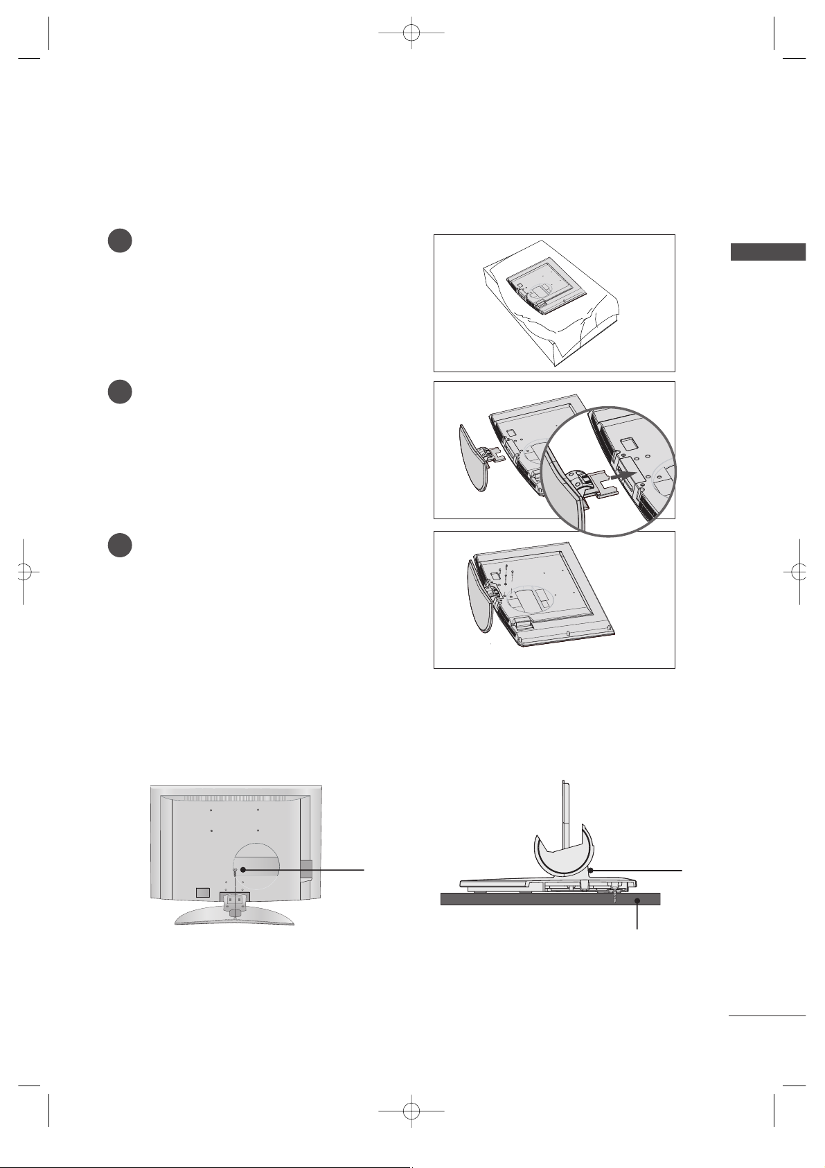
STAND INSTALLATION (Only 32LB9RT*)
PREPARATION
1
2
3
Carefully place the product screen side down on
a cushioned surface that will protect product and
screen from damage.
Assemble the product stand with the product as
shown.
Install the 4 bolts securely, in the back of the
product in the holes provided.
ATTACHING THE TV TO A DESK (Only 32LB9RT*)
If you wish to attach the TV to a desk, it must be securely fastened to the desk using a metal screw
(as shown below). Failure to securely attach the TV may result in the TV falling, which may cause
damage to the TV and serious personal injury.
1 bolt
Stand
Deck
MFL36546204en_1 12/31/07 2:02 PM Page 13

14
ATTACHING THE TV TO A WALL
PREPARATION
PREPARATION
2
1
A
Set it up close to the wall so the product doesn’t fall over when it is pushed backwards.
A
The instructions shown below is a safer way to set up the product, which is to fix it on the wall so the
product doesn’t fall over when it is pulled in the forward direction. It will prevent the product from
falling forward and hurting people. It will also prevent the product from damage caused by fall. Please
make sure that children don’t climb on or hang from the product.
NOTE
!
G
When moving the product to another place undo the ropes first.
G
Use a product holder or a cabinet that is big and strong enough for the size and weight of the product.
G
To use the product safely make sure that the height of the bracket that is mounted on the wall is same
as that of the product.
2
3
1
1
2
Use the eye-bolts or TV brackets/bolts to fix the product to the wall as shown in the picture.
(If your product has the bolts in the eye-bolts position before inserting the eye-bolts, loosen the bolts.)
* Insert the eye-bolts or TV brackets/bolts and tighten them securely in the upper holes.
Secure the wall brackets with the bolts (not provided as parts of the product, must purchase separately) on
the wall. Match the height of the bracket that is mounted on the wall.
3
Use a sturdy rope (not provided as parts of the product, must purchase separately) to tie the
product. It is safer to tie the rope so it becomes horizontal between the wall and the product.
* This feature is not available for all models.
MFL36546204en_1 12/31/07 2:02 PM Page 14
15
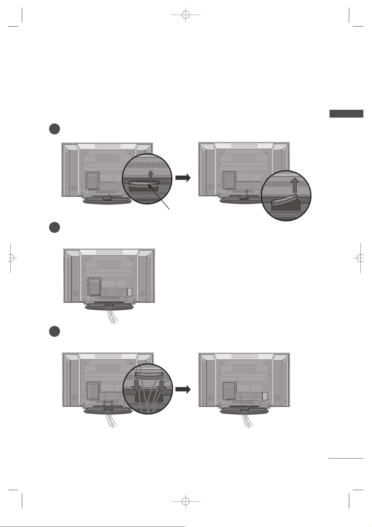
BACK COVER FOR WIRE ARRANGEMENT
PREPARATION
Plasma TV models
Connect the cables as necessary.
To connect an additional equipment, see the External equipment Setup section.
Reinstall the
CCAABBLLEE MMAANNAAGGEEMMEENNTT
as shown.
2
1
3
Hold the
CCAABBLLEE MMAANN AAGGEEMMEENNTT
with hands and push it as shown.
CABLE MANAGEMENT
MFL36546204en_1 12/31/07 2:02 PM Page 15
16
PREPARATION
PREPARATION
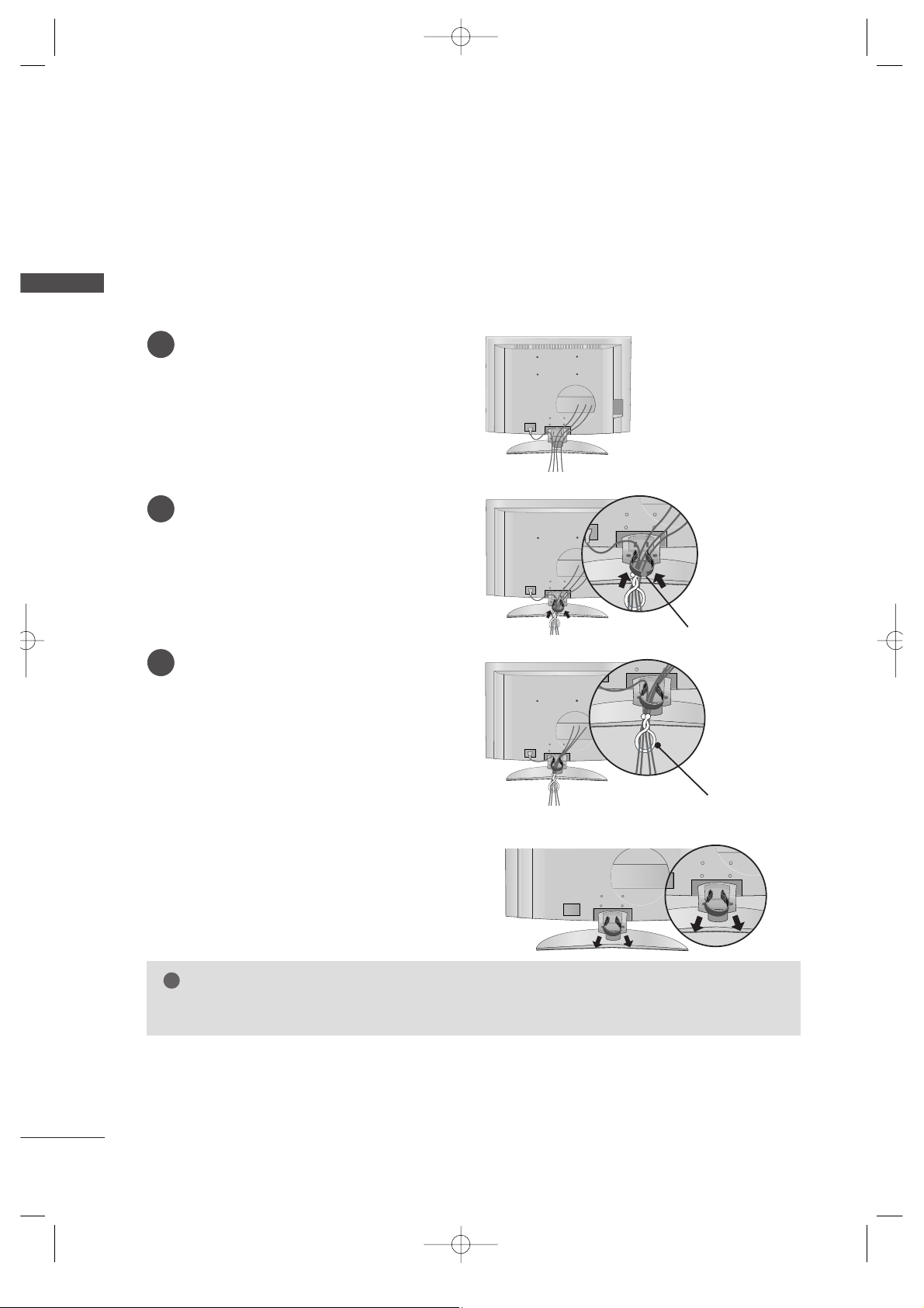
LCD TV models
1
2
3
■
Here shown may be somewhat different from your TV.
Connect the cables as necessary.
To connect an additional equipment, see the
EExxtteerrnnaall eeqquuiippmmeenntt CCoonnnneeccttiioonnss
section.
Install the
CCAABBLLEE MMAANNAAGGEEMMEENNTT
as shown.
(Insert it as pushing the loops on the both
sides of the cable management.)
Bundle the cables using the supplied twist
holder. (This feature is not available for all
models.)
Hold the
CC AA BB LLEE MMAA NN AA GG EE MMEENN TT
with both
hands and pull it out.
(Pull it out as holding the loops on the both sides of
the cable management.)
NOTE
!
GG
Do not hold the CABLE MANAGEMENT when moving the product.
- If the product is dropped, you may be injured or the product may be broken.
How to remove the cable management
CABLE MANAGEMENT
TWIST HOLDER
MFL36546204en_1 12/31/07 2:02 PM Page 16
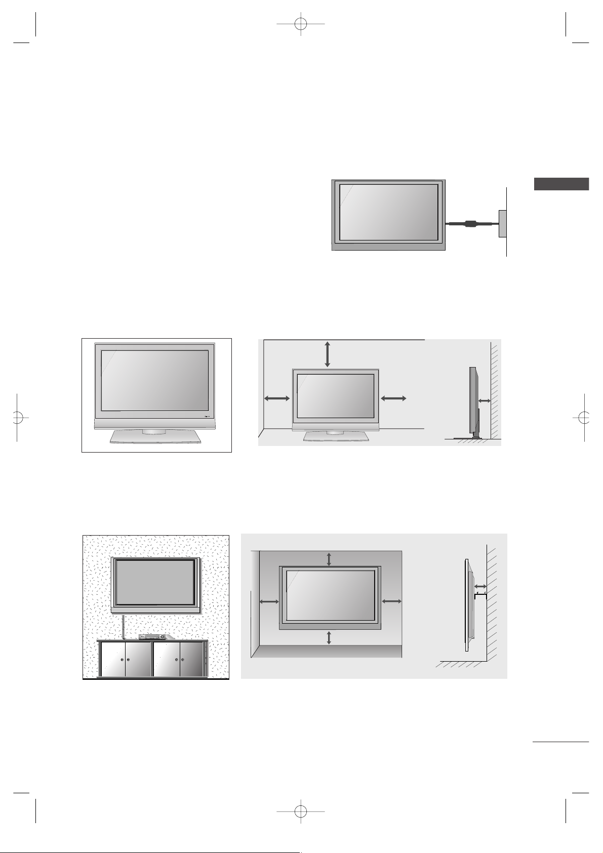
17
■
The TV can be installed in various ways such as on a wall, or on a desktop etc.
■
The TV is designed to be mounted horizontally.
PREPARATION
WALL MOUNT: HORIZONTAL INSTALLATION
For proper ventilation, allow a clearance of 4" on each side and from the wall. Detailed installation instructions are available from your dealer, see the optional Tilt Wall Mounting Bracket Installation and Setup Guide.
4 inches
4 inches
4 inches
4 inches
4 inches
Power Supply
Short-circuit
Breaker
GROUNDING
Ensure that you connect the earth ground wire to prevent
possible electric shock. If grounding methods are not possible, have a qualified electrician install a separate circuit
breaker.
Do not try to ground the unit by connecting it to telephone
wires, lightening rods, or gas pipes.
DESKTOP PEDESTAL INSTALLATION
For proper ventilation, allow a clearance of 4" on each side and from the wall.
4 inches
4 inches
4 inches
4 inches
MFL36546204en_1 12/31/07 2:02 PM Page 17
R
USB
AV IN 2
L/MONO
R
AUDIO
S-VIDEO
18
PREPARATION
PREPARATION
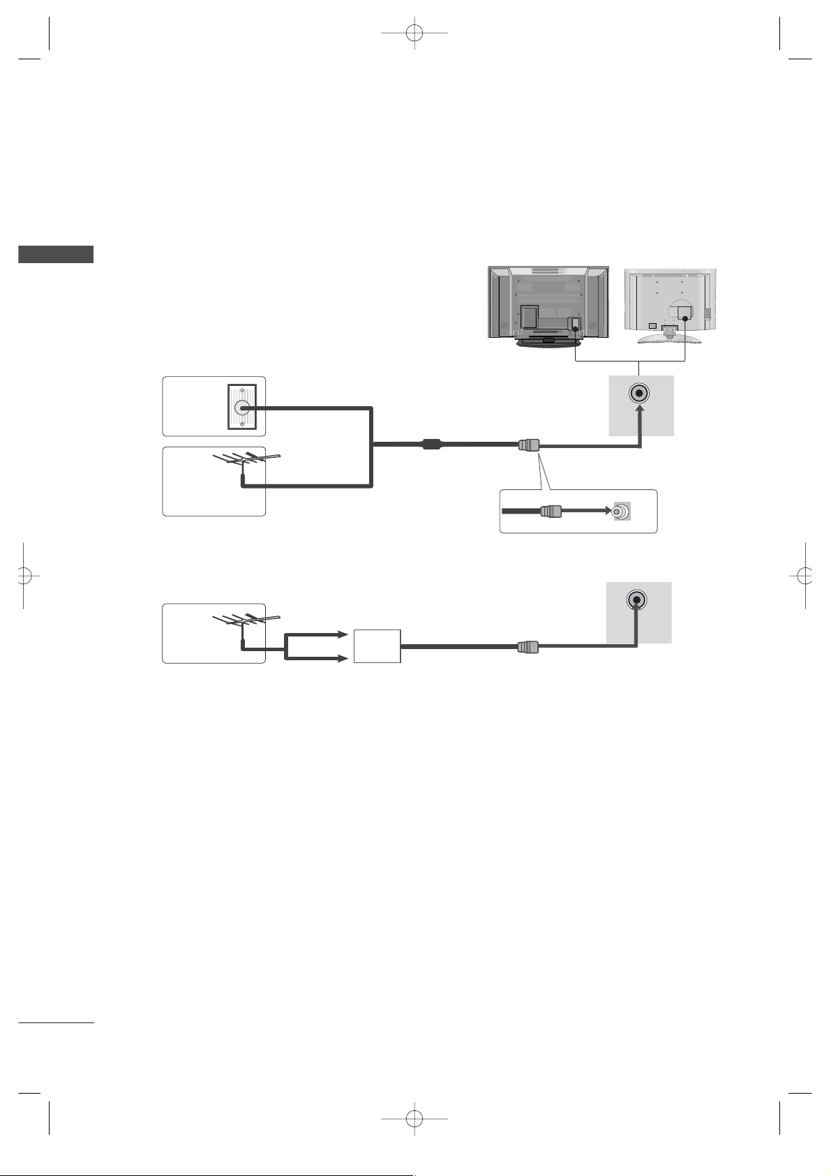
ANTENNA CONNECTION
■
To prevent the equipment damage, never plug in any power cords until you have finished connecting all equipment.
AV IN 2
L/MONO
R
AUDIO
VIDEO
USB IN
■
For optimum picture quality, adjust antenna direction.
■
An antenna cable and converter are not supplied.
Multi-family Dwellings/Apartments
(Connect to wall antenna socket)
Single-family Dwellings /Houses
(Connect to wall jack for outdoor antenna)
Outdoor
Antenna
Wall
Antenna
Socket
RF Coaxial Wire (75 ohm)
Antenna
UHF
Signal
Amplifier
VHF
■
In poor signal areas, to get better picture quality, install a signal amplifier to the antenna as shown to the right.
■
If signal needs to be split for two TVs, use an antenna signal splitter for connection.
MFL36546204en_1 12/31/07 2:02 PM Page 18
ANTENNA
IN
ANTENNA
IN
19
HD RECEIVER SETUP
EXTERNAL EQUIPMENT SETUP
EXTERNAL EQUIPMENT SETUP
1
1
2
2
VAAUVA
AU
COMPONENT INCOMPONENT IN
AUDIO
VIDEO
1
2
COMPONENT IN
AUDIO
VIDEO
HDMI/DVI IN
1
RGB IN
1 2
When connecting with a component cable
Connect the video outputs (Y, PB, PR
)
of the digital set
top box to the
CCOOMMPPOONNEENNTT II NN VVIIDD EEOO
jacks on the
set.
Connect the audio output of the digital set-top box to
the
CCOOMMPPOONNEENN TT II NN AA UU DD II OO
jacks on the set.
Turn on the digital set-top box.
(
Refer to the owner’s manual for the digital set-top box.
)
Select
CCoommppoonneenntt11
input source with using the
IINNPP UUTT
button on the remote control.
If connected to
CCOOMMPPOONNEENN TT IINN 22
, select
CCoommppoonneenntt22
input source.
2
3
4
1
Signal
480i
480p
720p/1080i
1080p(50/60Hz)
Component 1/2
Yes
Yes
Yes
Yes
HDMI1/DVI, HDMI2
No
Yes
Yes
Yes
■
To prevent the equipment damage, never plug in any power cords until you have finished connecting all equipment.
■
This part of EXTERNAL EQUIPMENT SETUP mainly use pictures for the LCD TV models.
MFL36546204en_1 12/31/07 2:02 PM Page 19
20
EXTERNAL EQUIPMENT SETUP
EXTERNAL EQUIPMENT SETUP
HDMI IN HDMI IN HDMI/DVI IN HDMI/DVI IN
1
1
2
2
COMPONENT INCOMPONENT IN
AUDIO
VIDEO
HDMI IN HDMI/DVI IN
1 2
1
2
COMPONENT IN
HDMI-DTV OUTPUT
HDMI/DVI IN
1
RGB IN
1
When connecting with a HDMI cable
Connect the HDMI output of the digital set-top box to
the
HHDDMMII//DDVV II IINN 11
or
HHDDMMII IINN 22
jack on the set.
Select
HHDDMMII11 //DDVVII
or
HHDDMMII22
input source with
using the
IINNPPUUTT
button on the remote control.
Turn on the digital set-top box.
(
Refer to the owner’s manual for the digital set-top box.
)
2
3
1
MFL36546204en_1 12/31/07 2:02 PM Page 20
21
EXTERNAL EQUIPMENT SETUP
HDMI IN HDMI IN HDMI/DVI IN HDMI/DVI IN
1
1
2
2
VARIABLE
AUDIO OUT
VARIABLE
AUDIO OUT
COMPONENT INCOMPONENT IN
AUDIO
VIDEO
AV IN 1AV IN 1 AV OUTAV OUT
AUDIO
(RGB/DVI)
RGB(PC)
RGB INRGB IN
R
S-232C
IN
(C
O
N
TR
O
L&
S
E
R
V
IC
E)
R
S-232C
IN
(C
O
N
TR
O
L&
S
E
R
V
IC
E)
L
/M
O
N
O
R
A
U
D
IO
V
ID
E
O
RGB(PC)
HDMI/DVI IN
1
AUDIO
(RGB/DVI)
RGB IN
1
2
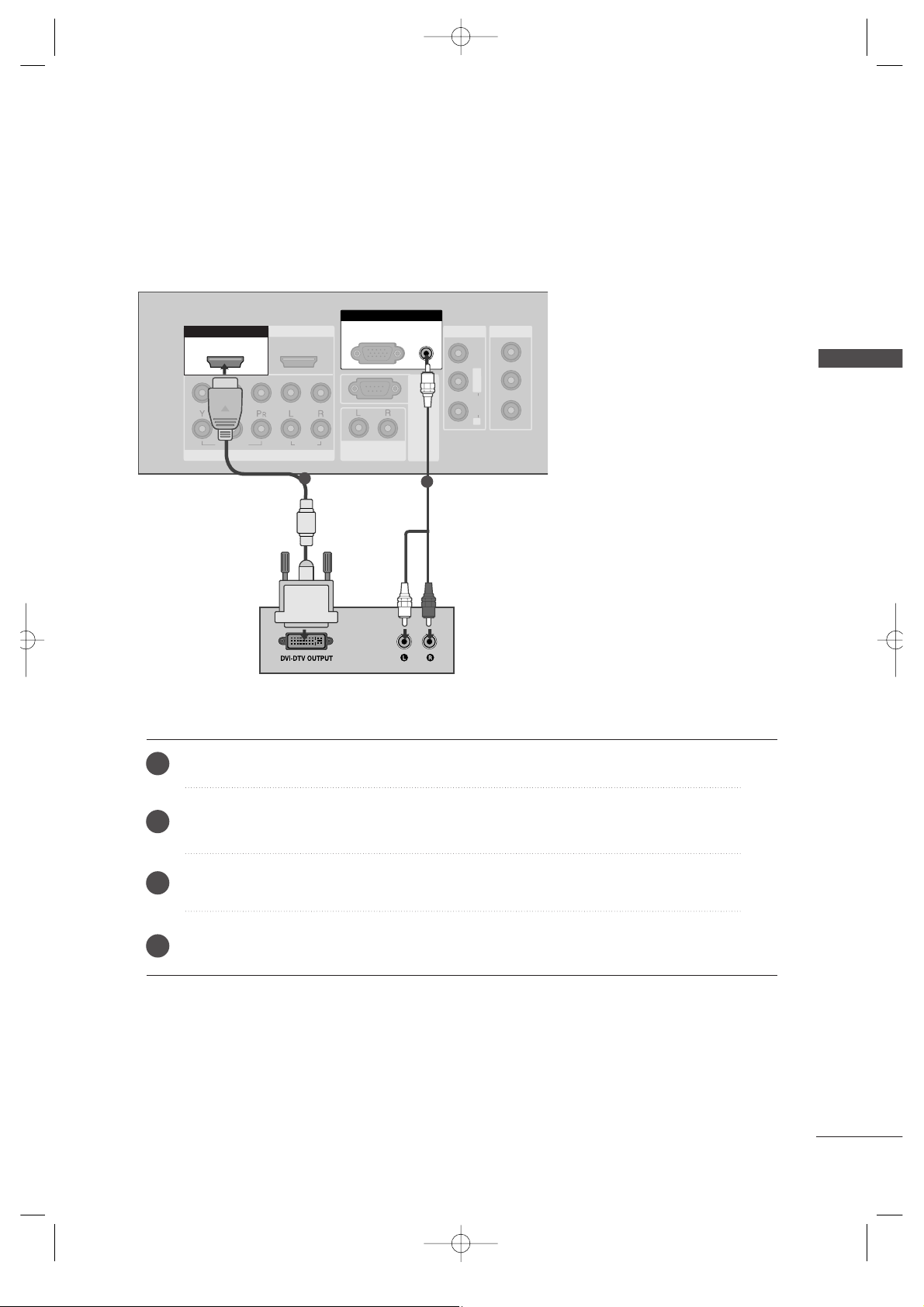
Connect the DVI output of the digital set-top box to the
HHDDMMII//DDVV II IINN 11
jack on the set.
Connect the audio output of the digital set-top box to the
AAUUDDIIOO((RR GG BB //DDVVII))
jack on the set.
Turn on the digital set-top box. (Refer to the owner’s manual for the digital set-top box.
)
Select
HHDDMMII11 //DDVVII
input source with using the
IINNPPUUTT
button on the remote control.
2
3
4
1
When connecting with a HDMI to DVI cable
MFL36546204en_1 12/31/07 2:02 PM Page 21
22
DVD SETUP
EXTERNAL EQUIPMENT SETUP
EXTERNAL EQUIPMENT SETUP
USB IN
AV IN 2
L/ MONO
R
AUDIO
VIDEO
S-VIDEO
1
2
VAV
A
COMPONENT INCOMPONENT IN
AUDIO
VIDEO
1
2
COMPONENT IN
AUDIO
VIDEO
1 2
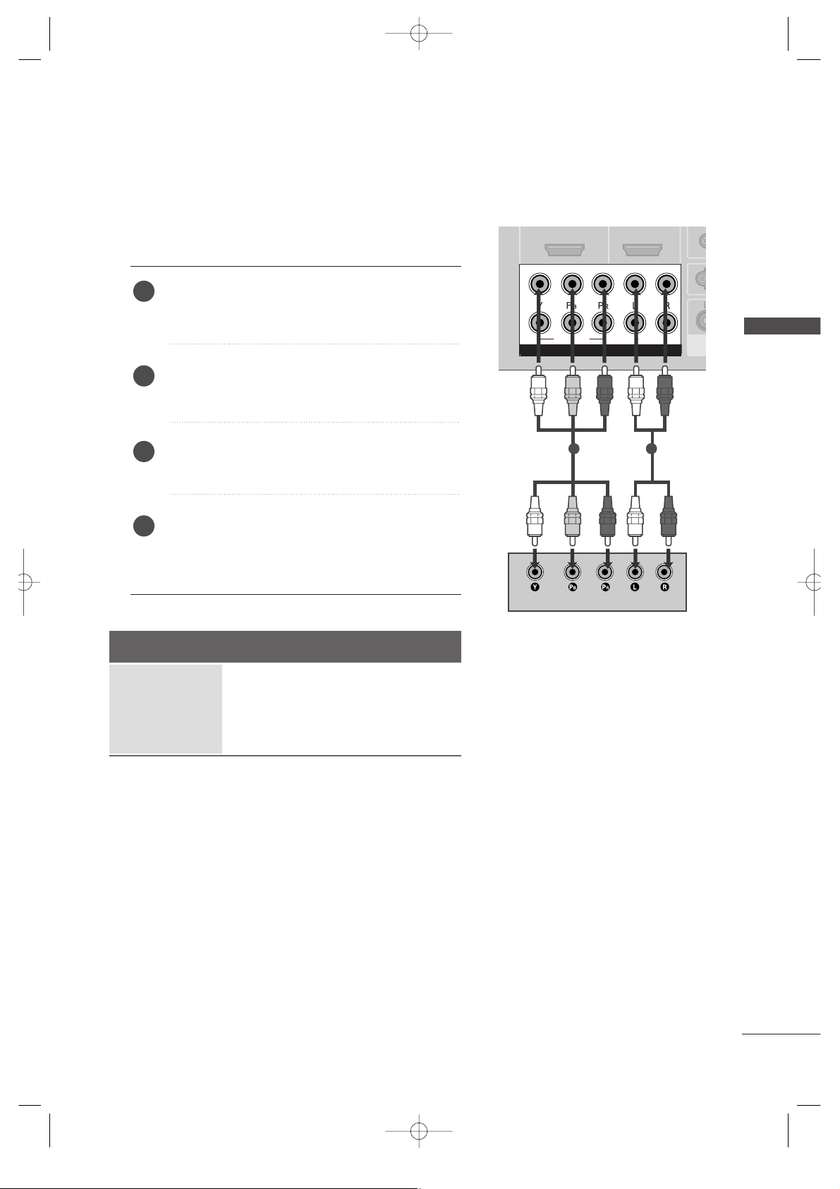
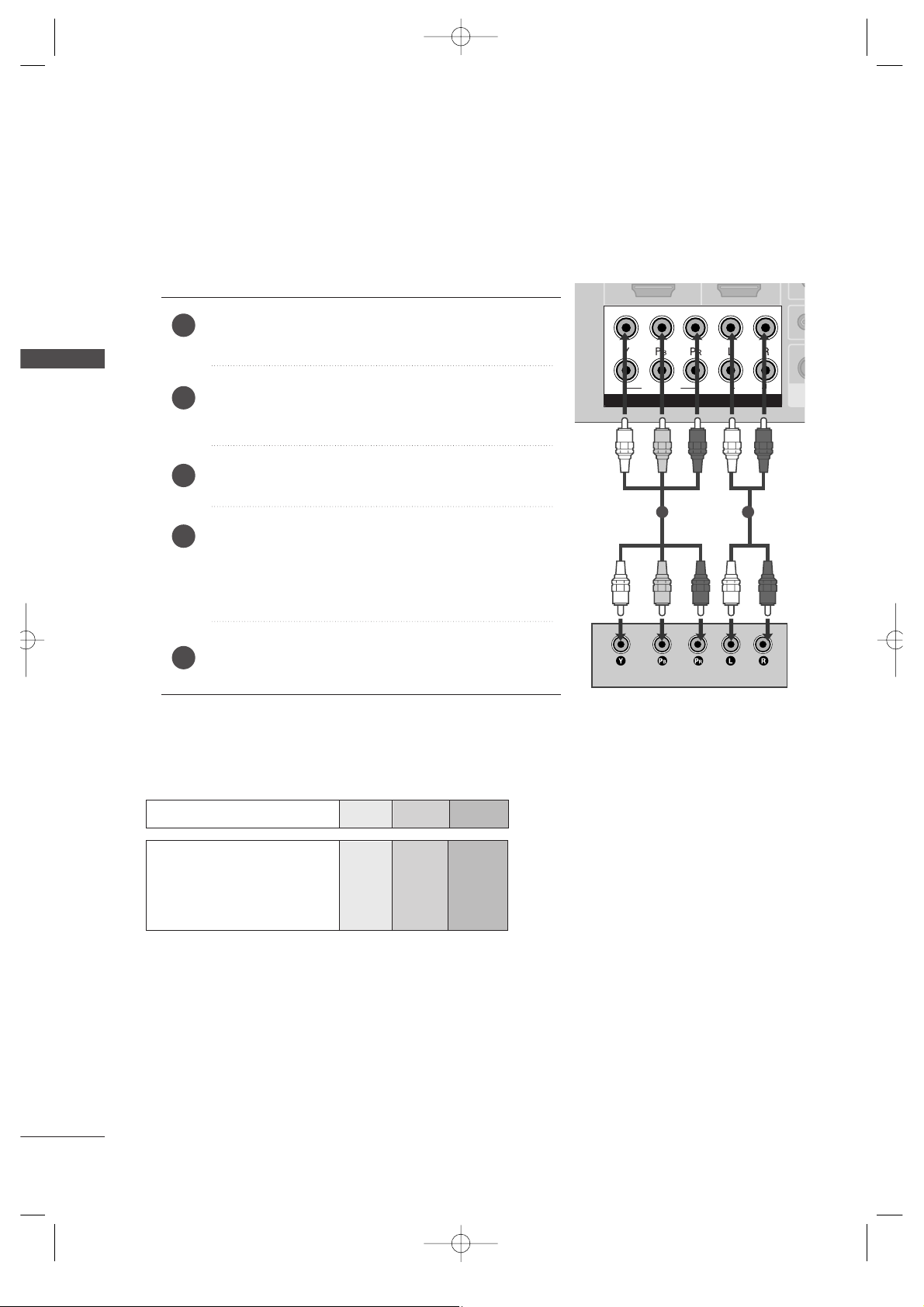
When connecting with a component cable
Component Input ports
To get better picture quality, connect a DVD player to the component input ports as shown below.
Component ports on the TV
YPB PR
Video output ports
on DVD player
Y
Y
Y
Y
PB
B-Y
Cb
Pb
P
R
R-Y
Cr
Pr
Connect the video outputs (Y, PB, PR
)
of the DVD to the
CCOOMMPPOONNEENNTT II NN VVIIDD EEOO
jacks on the set.
Connect the audio outputs of the DVD to the
CCOOMMPPOONNEENN TT II NN AA UU DD II OO
jacks on the set.
Turn on the DVD player, insert a DVD.
Select
CCoommppoonneenntt11
input source with using the
IINNPPUUTT
button on the remote control.
If connected to
CCOOMMPPOONN EENNTT IINN22
, select
CCoommppoonneenntt22
input source.
Refer to the DVD player's manual for operating instructions.
2
3
4
5
1
MFL36546204en_1 12/31/07 2:02 PM Page 22
23
EXTERNAL EQUIPMENT SETUP
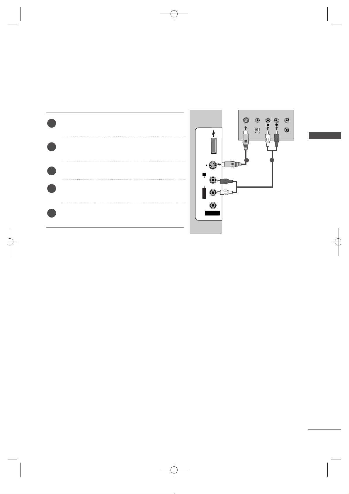
When connecting with an S-Video cable
Connect the S-VIDEO output of the DVD to the
SS --VVIIDD EEOO
input on the set.
Connect the audio outputs of the DVD to the
AAUUDDIIOO
input jacks on the set.
Turn on the DVD player, insert a DVD.
Select
AAVV22
input source with using the
IINNPPUUTT
button on the remote control.
Refer to the DVD player's manual for operating
instructions.
2
3
4
5
1
USB INUSB IN
AV IN 2
L/MONO
R
AUDIOAUDIO
VIDEOVIDEO
S-VIDEO
L
R
S-VIDEO
VIDEO
OUTPUT
SWITCH
ANT IN
ANT OUT
1
2
MFL36546204en_1 12/31/07 2:02 PM Page 23
24
EXTERNAL EQUIPMENT SETUP
EXTERNAL EQUIPMENT SETUP
HDMI IN HDMI IN HDMI/DVI IN HDMI/DVI IN
1
1
2
2
VAV
A
COMPONENT INCOMPONENT IN
AUDIO
VIDEO
HDMI IN HDMI/DVI IN
1 2
HDMI-DTV OUTPUT
USB IN
AV IN 2
L/ MONO
R
AUDIO
VIDEO
S-VIDEO
1
2
COMPONENT IN
1
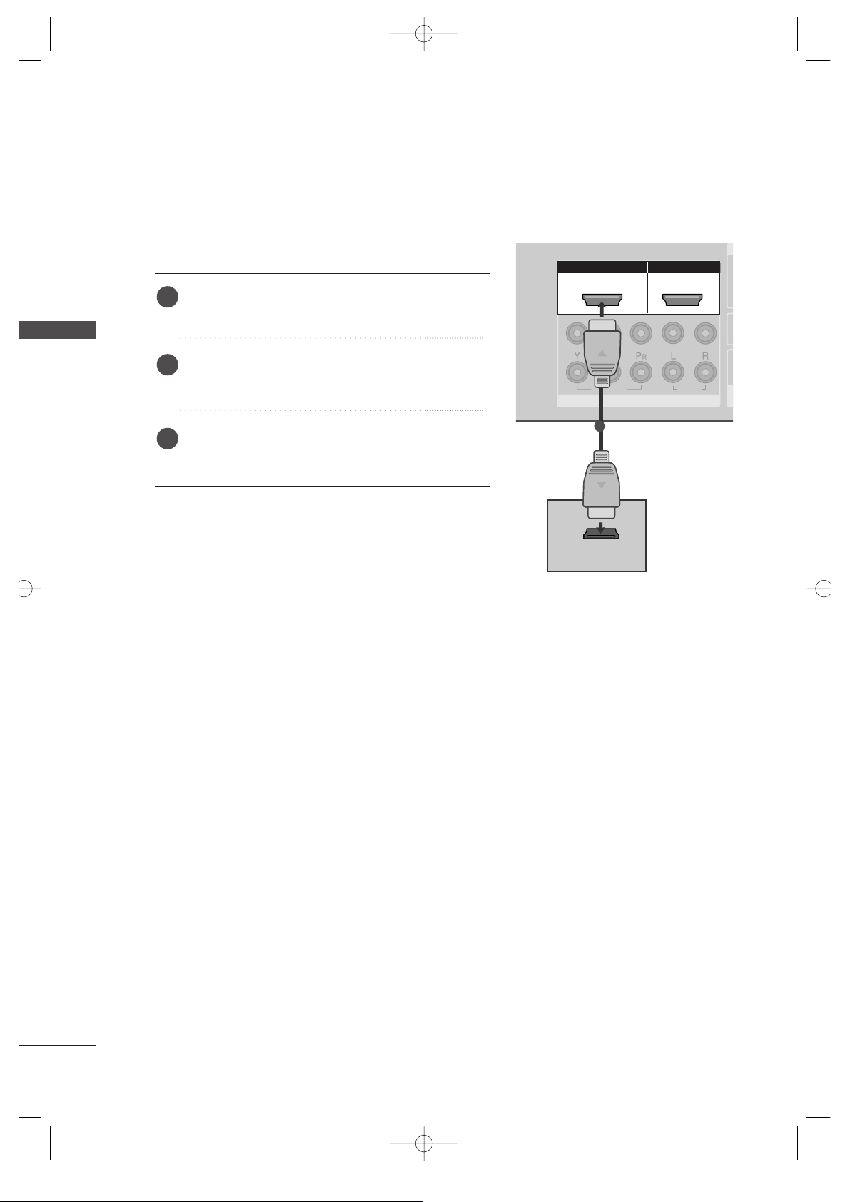
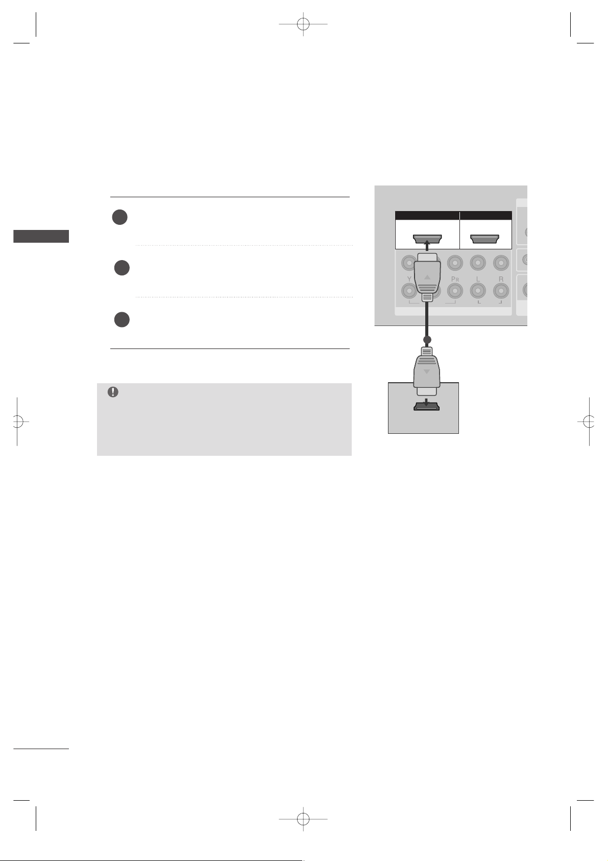
When connecting HDMI cable
Connect the HDMI output of the DVD to the
HHDDMMII//DDVV II IINN 11
or
HHDDMMII IINN 22
jack on the set.
Select
HHDDMMII11 //DDVVIIorHHDDMMII22
input source with
using the
IINNPPUUTT
button on the remote control.
Refer to the DVD player's manual for operating
instructions.
1
2
3
GG
TV can receive the video and audio signal simultaneously
with using a HDMI cable.
GG
If the DVD does not support Auto HDMI, you need to set
the output resolution appropriately.
NOTE
MFL36546204en_1 12/31/07 2:02 PM Page 24
25
VCR SETUP
EXTERNAL EQUIPMENT SETUP
AV IN 1AV IN 1 AV OUTAV OUT
ANTENNA
IN
ANTENNA
IN
AUDIO
(RGB/DVI)
RS-232C IN
(CONTROL&SERVICE)
RS-232C IN
(CONTROL&SERVICE)
L
/M
O
N
O
R
AUDIO
V
ID
E
O
ANTENNA
IN
OUTPUT
SWITCH
ANT IN
R
S-VIDEO VIDEO
ANT OUT
L
USB IN
AV IN 2
L/ MONO
R
AUDIO
VIDEO
S-VIDEO
Wall Jack
Antenna
1
When connecting with an antenna
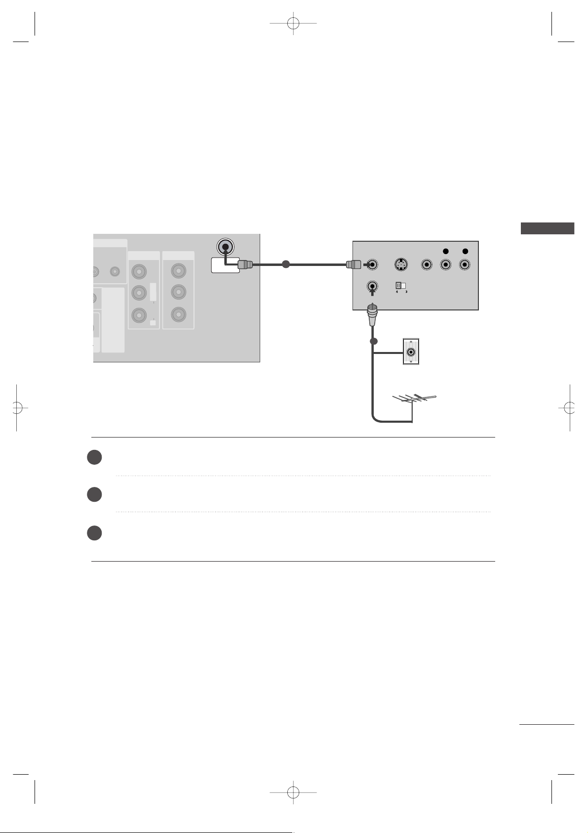
■
To avoid picture noise (interference), leave an adequate distance between the VCR and TV.
■
Typically a frozen still picture from a VCR. If the 4:3 picture format is used; the fixed images on the sides of
the screen may remain visible on the screen.
Connect the
AANN TT OOUUTT
socket of the VCR to the
AANN TTEENNNNAA IINN
socket on the set.
Connect the antenna cable to the
AANN TT IINN
socket of the VCR.
Press the
PPLLAAYY
button on the VCR and match the appropriate program between the TV and VCR for
viewing.
1
2
2
3
1
MFL36546204en_1 12/31/07 2:02 PM Page 25
26
EXTERNAL EQUIPMENT SETUP
EXTERNAL EQUIPMENT SETUP
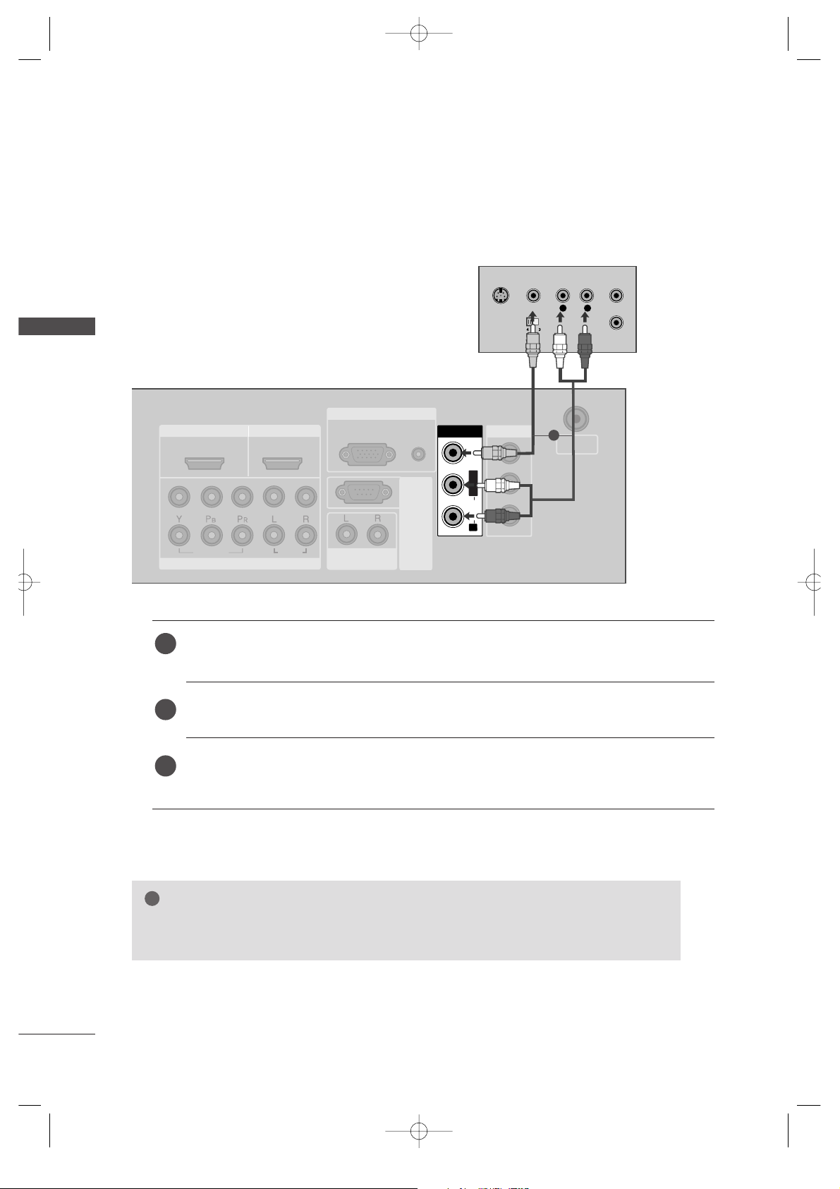
When connecting with a RCA cable
HDMI IN HDMI IN HDMI/DVI IN HDMI/DVI IN
1
1
2
2
VARIABLE
AUDIO OUT
VARIABLE
AUDIO OUT
COMPONENT INCOMPONENT IN
AUDIO
VIDEO
AV I N 1AV I N 1 AV OUTAV OUT
ANTENNA
IN
ANTENNA
IN
AUDIO
(RGB/DVI)
RGB(PC)
RGB INRGB IN
RS-232C IN
(CONTROL&SERVICE)
RS-232C IN
(CONTROL&SERVICE)
L
/M
O
N
O
R
AUDIO
V
ID
E
O
AV IN 1
L/L
/M
O
N
O
M
O
N
O
R
AUDIOAUDIO
V
ID
E
O
V
ID
E
O
L
R
S-VIDEO
VIDEO
OUTPUT
SWITCH
ANT IN
ANT OUT
Connect the
AAUUDDIIOO/VVIIDDEEOO
jacks between TV and VCR. Match the jack colors (Video = yellow,
Audio Left = white, and Audio Right = red)
Insert a video tape into the VCR and press PLAY on the VCR. (Refer to the VCR owner’s manual.
)
Select
AAVV11
input source using the
IINNPPUUTT
button on the remote control.
If connected to
AAVV IINN22
, select
AV2 input source.
1
2
3
GG
If you have a mono VCR, connect the audio cable from the VCR to the
AAUUDDIIOO LL//MMOONNOO
jack
of the set.
NOTE
!
1
MFL36546204en_1 12/31/07 2:02 PM Page 26
EXTERNAL EQUIPMENT SETUP
27
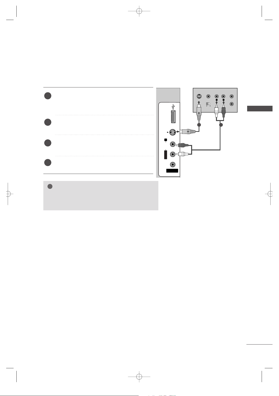
GG
If both S-VIDEO and VIDEO sockets have been connected to
the S-VHS VCR simultaneously, only the S-VIDEO can be
received.
NOTE
!
USB INUSB IN
AV IN 2
L/MONO
R
AUDIOAUDIO
VIDEOVIDEO
S-VIDEO
L
R
S-VIDEO
VIDEO
OUTPUT
SWITCH
ANT IN
ANT OUT
When connecting with an S-Video cable
Connect the S-VIDEO output of the VCR to the
SS --VVIIDD EEOO
input on the set. The picture quality is
improved; compared to normal composite (RCA cable)
input.
Connect the audio outputs of the VCR to the
AAUUDDIIOO
input jacks on the set.
Insert a video tape into the VCR and press PLAY on
the VCR. (Refer to the VCR owner’s manual.)
Select
AAVV22
input source with using the
IINNPPUUTT
button on the remote control.
2
3
4
1
1 2
MFL36546204en_1 12/31/07 2:02 PM Page 27
28
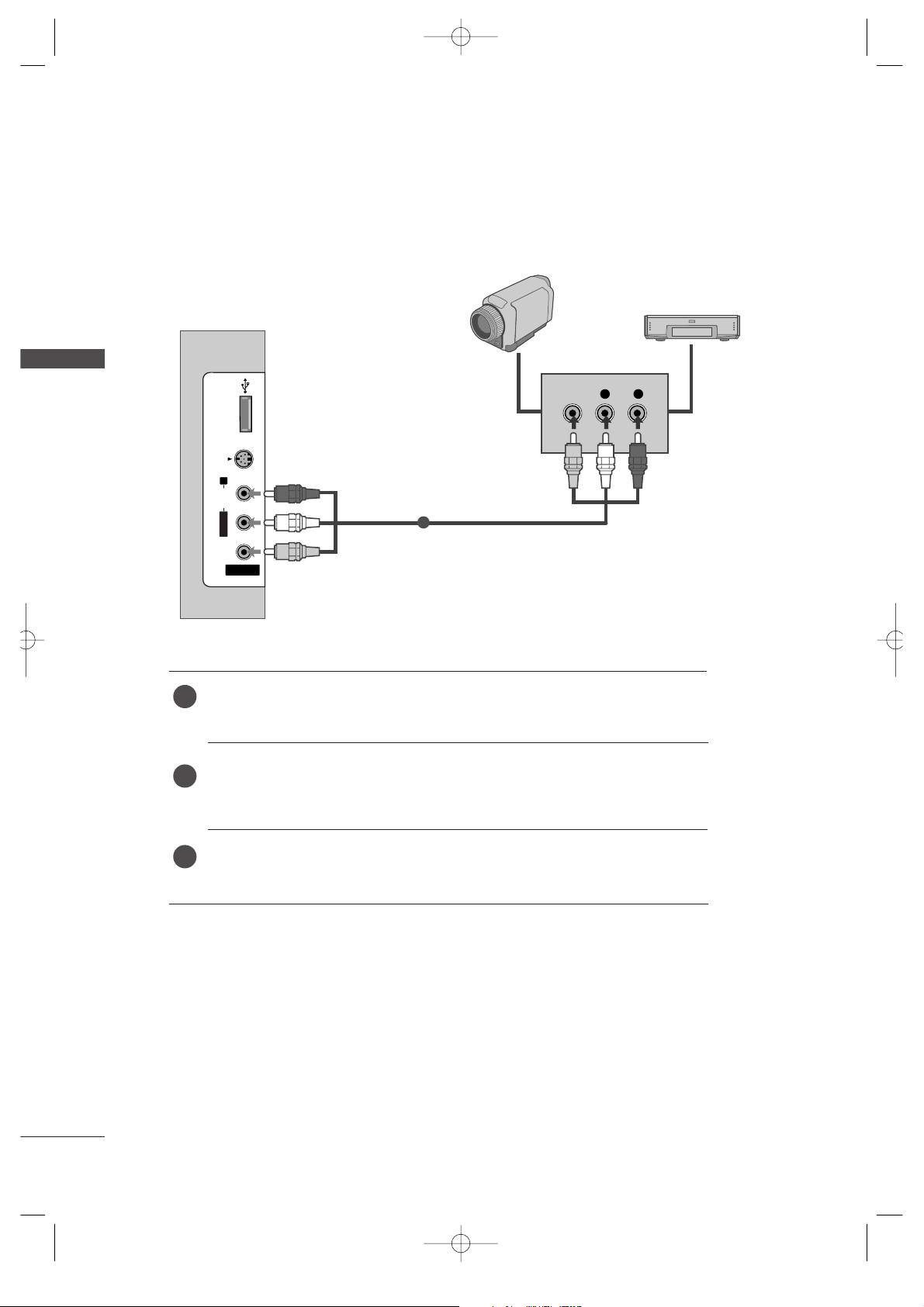
OTHER A/V SOURCE SETUP
EXTERNAL EQUIPMENT SETUP
EXTERNAL EQUIPMENT SETUP
USB INUSB IN
AV IN 2
L/MONO
R
AUDIOAUDIO
VIDEOVIDEO
S-VIDEO
L R
VIDEO
Camcorder
Video Game Set
1
Connect the
AAUUDDIIOO/VVIIDDEEOO
jacks between TV and external equipment.
Match the jack colors
. (Video = yellow, Audio Left = white, and Audio Right = red
)
Select
AAVV22
input source with using the
IINNPPUUTT
button on the remote control.
If connected to
AAVV IINN11
, select
AAVV11
input source.
Operate the corresponding external equipment.
Refer to external equipment operating guide.
1
2
3
MFL36546204en_1 12/31/07 2:02 PM Page 28
 Loading...