


LCD TV
OWNER’S MANUAL
LCD TV MODELS
42LB7RF
*
47LB7RF
*
Please read this manual carefully before operating your set.
Retain it for future reference.
Record model number and serial number of the set.
See the label attached on the back cover and quote
this information to your dealer when you require service.
ENGLISH
PP//NNOO:: MMFFLL 3377445577770099 ((00770022--RREEVV 0000))
PPrriinnttee dd iinn KK oorr eeaa

1
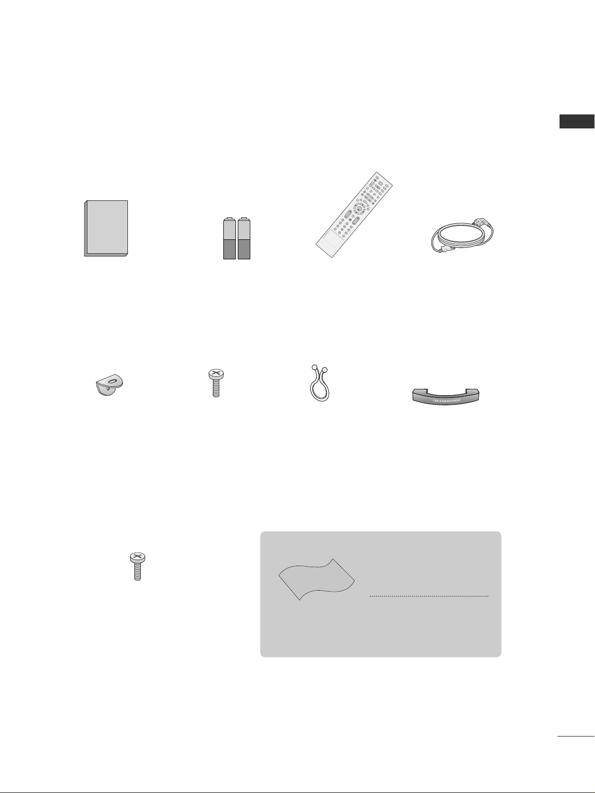
ACCESSORIES
Ensure that the following accessories are included with your TV. If an accessory is missing, please contact the
dealer where you purchased the product.
Owner's
Manual
Owner’s Manual
Batteries
Remote Control
Power Cord
2- TV Brackets
2- Wall Brackets
2-bolts
Twister Holder
Arrange the wires
with the twister
holder.
ACCESSORIES
Polishing Cloth
Polish the screen with the cloth
*
Slightly wipe stained spot on the
exterior only with the cleansing
cloths for the product exterior if
there is stain or fingerprint on surface
of the exterior.
Do not wipe roughly when removing
stain. Please be cautious of that
excessive power may cause scratch
or discoloration.
Cable Management
O
K
E
X
I
T
VOL PR
L
I
S
T
M
123
45
7
F
A
V
M
U
T
E
O
K
INP
UT
MO
DE
T
V
TV
D
VD
R
A
T
I
O
E
X
I
T
VOL
POSITION
PR
P
I
P
S
L
E
E
P
L
I
S
T
Q
.
V
I
E
W
I/II
ME
NU
S
I
Z
E
VC
R
P
I
P
P
R
P
I
P
P
R
+
P
I
P
I
N
P
U
T
P
OWE
R
123
456
789
0
F
A
V
S
I
M
P
L
I
N
K
I
N
P
U
T
M
U
T
E
S
W
A
P
4-bolts for stand assembly
(Refer to p.6)
2
CONTENTS
CONTENTS
AACCCCEESSSSOORRIIEESS
.....................................................1
PICTURE CONTROL
Watching PIP(Picture-in-Picture) .............................47
Picture Size (Aspect Ratio)Control.........................49
Preset Picture Settings
- Picture Mode-Preset............................................51
- Auto Colour Tone Control(Warm/Medium/Cool)
52
Manual Picture Adjustment
- Picture Mode-User Option................................53
- Colour Tone - User Option...............................54
-
Picture Improvement Technology
...................55
Advanced - Cinema 3:2 Pulldown Mode...............56
Advanced - Black(Darkness) Level...........................57
Picture Reset..................................................................58
Demo .................................................................59
WATCHING TV /PROGRAMME CONTROL
Remote Control Key Functions.................................32
Turning on the TV....................................................... 34
Programme Selection ................................................. 34
Volume Adjustment......................................................34
On Screen Menus Selection and Adjustment ......35
Auto Programme Tuning............................................ 36
Manual Programme Tuning ....................................... 37
Fine Tuning .....................................................................38
Assigning a Station Name..........................................39
Programme Edit ........................................................... 40
Favourite Programme .................................................. 41
Calling the Programme List....................................... 42
Input Source Selection.............................................. 43
................................................................ 44
Key lock.......................................................................... 46
PICTURE CONTROL
WATCHING TV / PROGRAMME CONTROL
PREPARATION
Front Panel Controls..................................................... 4
Back Panel Information ................................................ 5
Stand Installation........................................................... 6
Attaching the TV to a Wall ...........................................7
Back Cover for Wire Arrangement ............................ 8
Desktop Pedestal Installation..................................... 9
Wall Mount: Horizontal installation ........................ 10
Antenna Connection................................................... 11
EXTERNAL EQUIPMENT SETUP
HD Receiver Setup .......................................................12
DVD Setup..................................................................... 15
VCR Setup ..................................................................... 18
Other A/V Source Setup........................................... 21
PC Setup.........................................................................22
- Screen Setup for PC Mode................................26
AV OUTPUT Setup..................................................... 30
External Stereo Setup................................................. 31
PREPARATION

3
CONTENTS
SOUND & LANGUAGE CONTROL
Preset Sound Settings - Sound Mode....................60
Sound Setting Adjustment - User Mode ...............61
Auto Volume Leveler ....................................................62
Balance ............................................................................63
TV Speakers On/Off Setup .......................................64
I/II
- Stereo/Dual Reception.......................................65
- NICAM Reception................................................66
- Speaker Sound Output Selection....................66
On-Screen Menu Language Selection
...................... 67
APPENDIX
Troubleshooting............................................................72
Maintenance .................................................................74
Product Specifications ................................................75
Programming the Remote Control ........................ 76
IR Code ...........................................................................78
External Control Device Setup .................................80
TIME SETTING
Clock Setting .................................................................68
Auto On/Off Timer Setting .......................................69
Sleep Timer Setting......................................................70
Auto Shut-Off Setting..................................................71
4
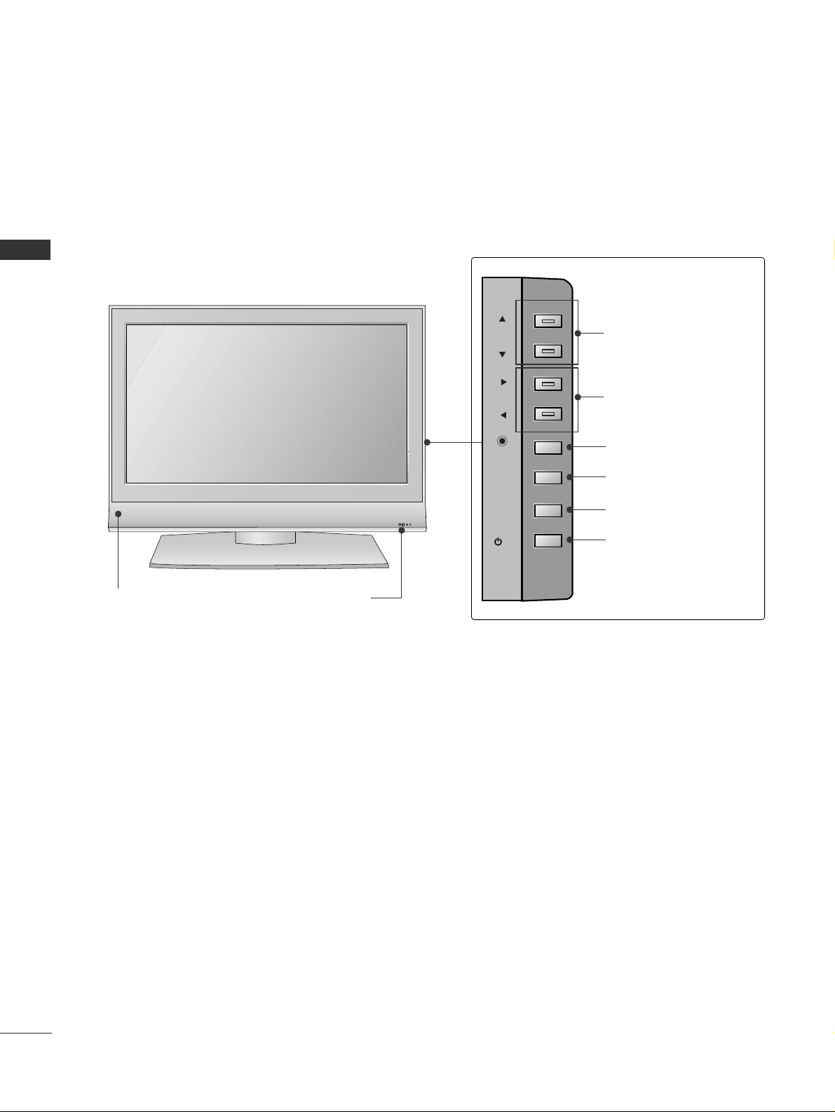
FRONT PANEL CONTROLS
PREPARATION
PREPARATION
■
This is a simplified representation of the front panel. Here shown may be somewhat different from your TV.
■
If your TV has the protection film, wipe the stand with polishing cloth after removing the protection film
attached to the stand.
R
Remote Control Sensor
Power/Standby Indicator
• illuminates red in standby mode.
• illuminates green when the set is switched on.
PROGRAMME Buttons
VOLUME Buttons
OK Button
MENU Button
INPUT Button
POWER Button
Intelligent Eye
PR
VOL
OK
MENU
INPUT
/I
5
PREPARATION
AV IN 2
L/MONO
R
AUDIO
VIDEO
S-VIDEO
8
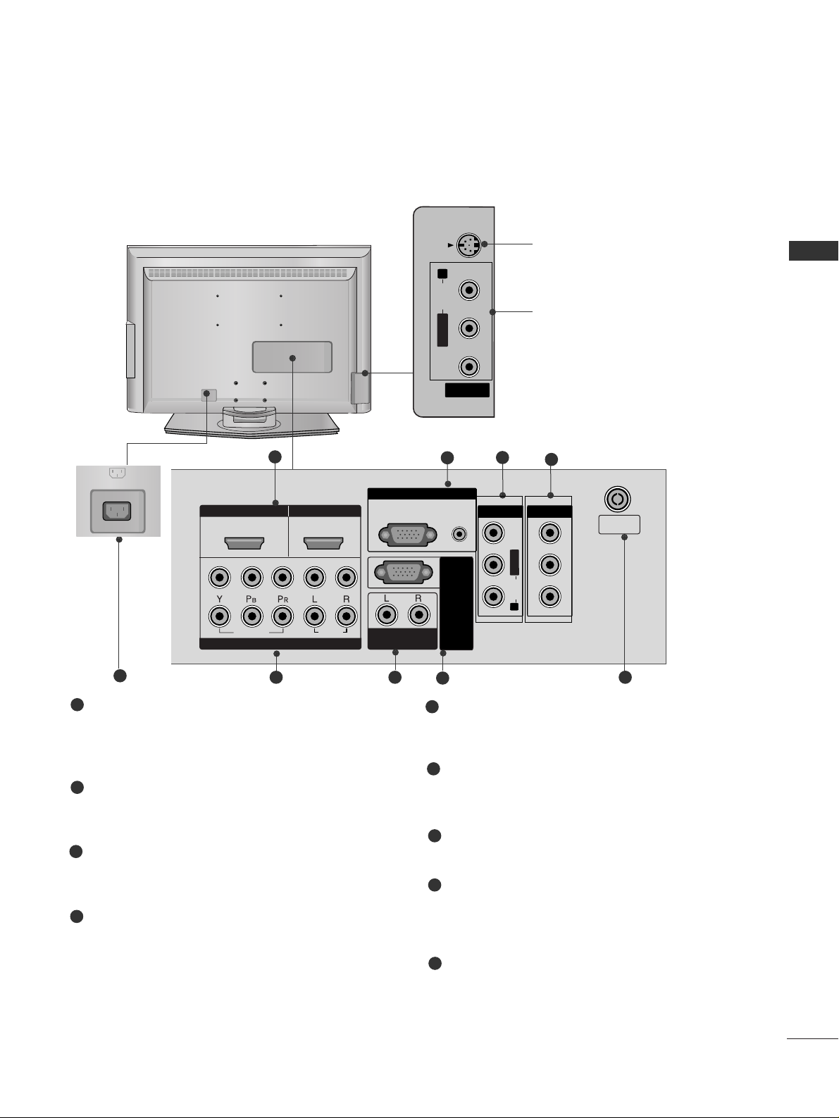
S-Video Input
Connect S-Video out from an
S-VIDEO device.
Audio/Video Input
Connect audio/video output
from an external device to
these jacks.
AV IN 2
L/MONO
R
AUDIOAUDIO
VIDEOVIDEO
S-VIDEO
AV IN 2
L/ MONO
R
AUDIO
VIDEO
S-VIDEO
HDMI IN HDMI/DVI IN
1
1
2
2
V
ARIABLE
AUDIO OUT
COMPONENT IN
AV IN 1 AV OUT
RGB IN
RS-232C IN
(CONTROL&SERVICE)
L/MONO
R
AUDIO
VIDEO
2
1
43
5
7
6
HDMI/DVI1, HDMI2 Input
Connect a HDMI signal to HDMI IN.
Or DVI(VIDEO)signal to HDMI/DVI port with DVI
to HDMI cable.
RGB/Audio Input
Connect the monitor output from a PC(only
Audio) to the appropriate input port.
Component Input 1/2
Connect a component video/audio device to
these jacks.
Variable Audio Output
Connect an external amplifier or add a subwoofer
to your surround sound system.
Audio/Video Input (AV IN 1)
Connect audio/video output from an external
device to these jacks.
AV Output
Connect second TV or monitor to the AV OUT
socket on the set.
Antenna Input
Connect over-the-air signals to this jack.
Power Cord Socket
This TV operates on an AC power. The voltage is
indicated on the Specifications page. Never
attempt to operate the TV on DC power.
RS-232C Input
(CONTROL&SERVICE)
Port
Connect the serial port of the control devices
to the RS-232C jack.
1
2
3
4
5
6
7
8
9
9
AC IN
AV IN 3
L/MONO
R
AUDIO
VIDEO
S-VIDEO
12
VARIABLE
AUDIO OUT
RGB IN
COMPONENT IN
AUDIO
VIDEO
AV 1 AV 2
ANTENNA
IN
HDMI/DVI IN HDMI IN
■
This is a simplified representation of the back panel. Here shown may be somewhat different from your TV.
BACK PANEL INFORMATION
HDMI IN
AUDIO
VIDEO
COMPONENT IN
RGB
(PC)
ARIABLE
AUDIO
(RGB/DVI)
VIDEO
AUDIO
ANTENNA
IN
6
PREPARATION
PREPARATION
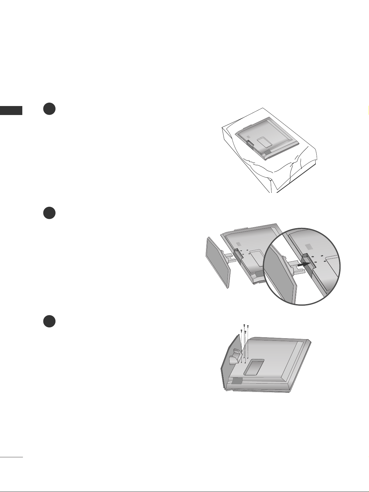
STAND INSTALLATION
1
2
3
Carefully place the product screen side down on
a cushioned surface that will protect product and
screen from damage.
Assemble the product stand with the product as
shown.
Install the 4 bolts securely, in the back of the
product in the holes provided.
7
PREPARATION
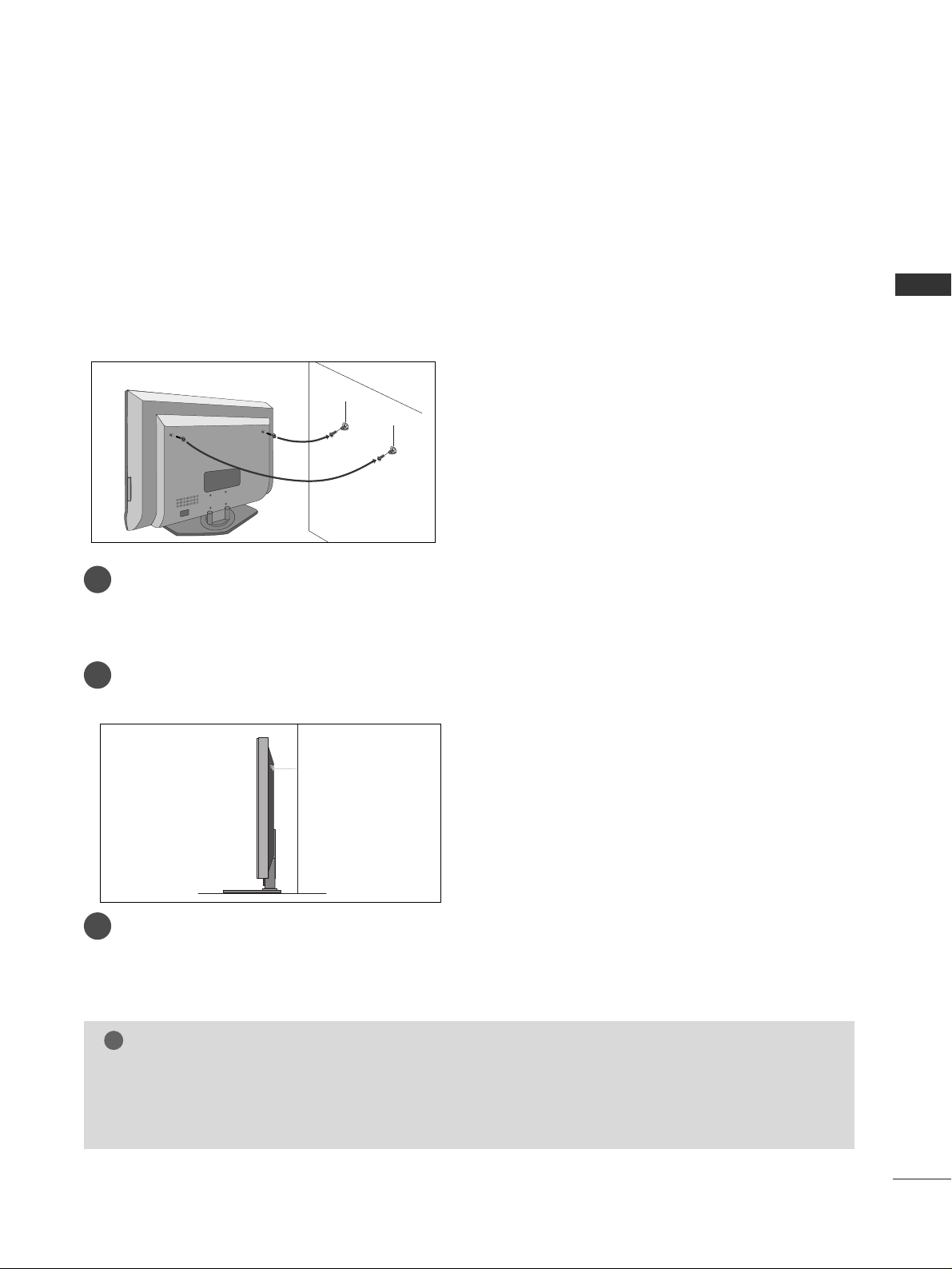
ATTACHING THE TV TO A WALL
LCD TV models
2
1
A
Set it up close to the wall so the product doesn’t fall over when it is pushed backwards.
A
The instructions shown below is a safer way to set up the product, which is to fix it on the wall so the
product doesn’t fall over when it is pulled in the forward direction. It will prevent the product from
falling for-ward and hurting people. It will also prevent the product from damage caused by fall. Please
make sure that children don’t climb on or hang from the product.
NOTE
!
G
When moving the product to another place undo the ropes first.
G
Use a product holder or a cabinet that is big and strong enough for the size and weight of the product.
G
To use the product safely make sure that the height of the bracket that is mounted on the wall is same
as that of the product.
3
1
2
Use the eye-bolts or TV brackets/bolts to fix the product to the wall as shown in the picture.
(If your product has the bolts in the eye-bolts position before inserting the eye-bolts, loosen the bolts.)
* Insert the eye-bolts or TV brackets/bolts and tighten them securely in the upper holes.
Secure the wall brackets with the bolts (not provided as parts of the product, must purchase separately) on
the wall. Match the height of the bracket that is mounted on the wall.
3
Use a sturdy rope (not provided as parts of the product, must purchase separately) to tie the
product. It is safer to tie the rope so it becomes horizontal between the wall and the product.
8
PREPARATION
PREPARATION
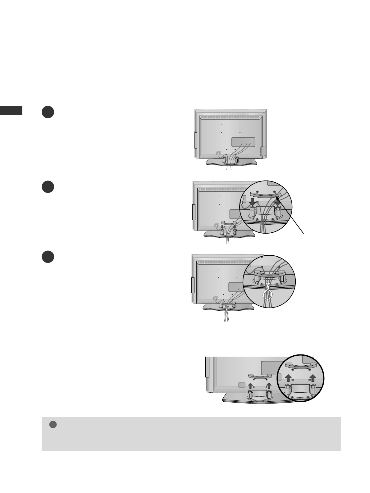
Connect the cables as necessary.
To connect an additional equipment, see the
EExxtteerrnnaall eeqquuiippmmeenntt CCoonnnneeccttiioonnss
section.
1
Install the
CC AA BBLLEE MMAANNAAGG EEMMEENNTT
as shown.
2
Bundle the cables using the supplied twister
holder.
3
Hold the
CC AABBLL EE MMAANNAAGG EEMMEE NN TT
with both
hands and pull it upward.
NOTE
!
GG
Do not hold the CABLE MANAGEMENT when moving the product.
- If the product is dropped, you may be injured or the product may be broken.
How to remove the cable management
CABLE MANAGEMENT
BACK COVER FOR WIRE ARRANGEMENT
9
PREPARATION
■
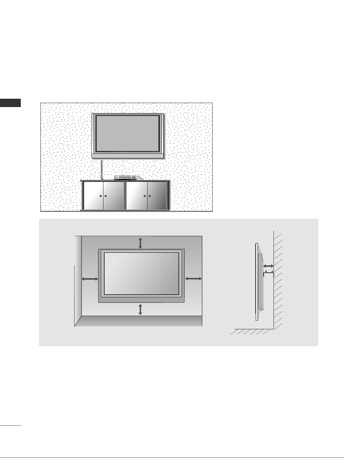
The TV can be installed in various ways such as on a wall, or on a desktop etc.
■
The TV is designed to be mounted horizontally.
DESKTOP PEDESTAL INSTALLATION
For proper ventilation, allow a clearance of 4inches on each side from the wall.
4 inches
4 inches
4 inches
4 inches
Power Supply
Short-circuit Breaker
GROUNDING
Ensure that you connect the earth ground wire to prevent possible electric shock. If grounding methods
are not possible, have a qualified electrician install a separate circuit breaker.
Do not try to ground the unit by connecting it to telephone wires, lightening rods, or gas pipes.
10
PREPARATION
PREPARATION
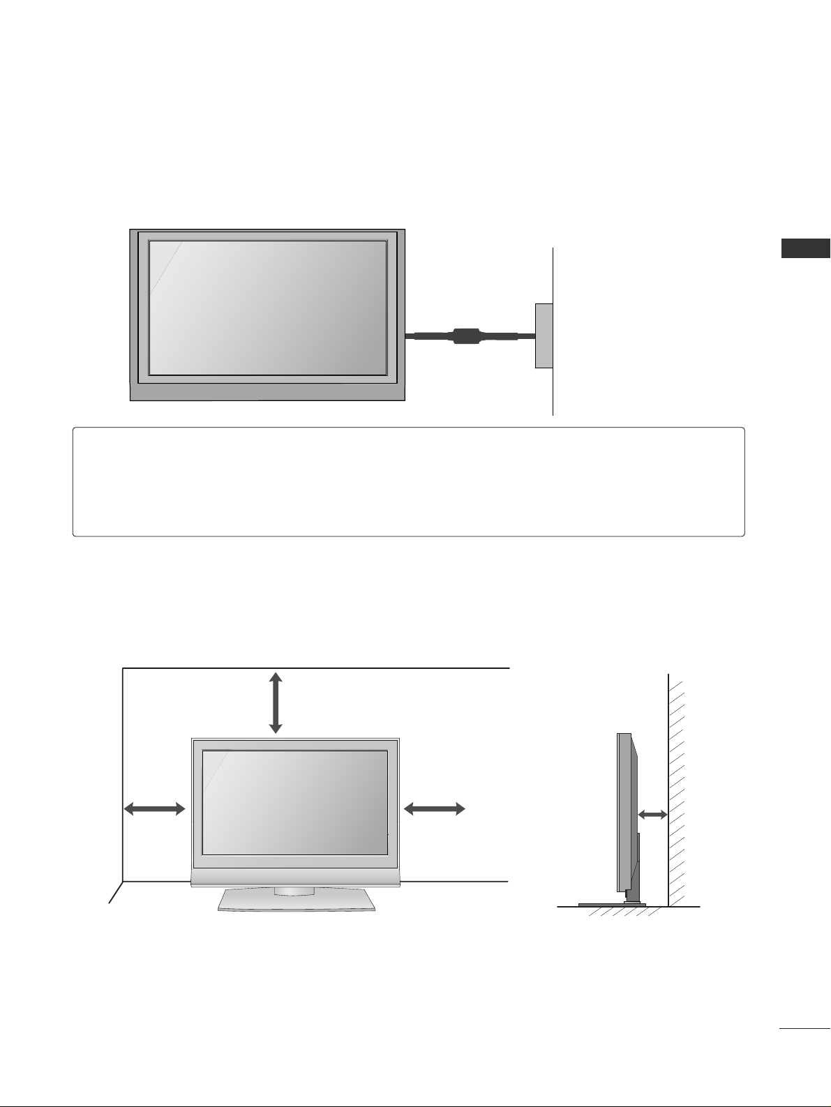
WALL MOUNT: HORIZONTAL INSTALLATION
For proper ventilation, allow a clearance of 4" on each side and from the wall.
Detailed installation instruc-tions are available from your dealer.
4 inches
4 inches
4 inches
4 inches
4 inches
AV IN 2
L/ MONO
R
AUDIO
VIDEO
S-VIDEO
ANTENNA
IN
11
PREPARATION
AV IN 3
L/MONO
R
AUDIO
VIDEO
S-VIDEO
AV IN 2
L/ MONO
R
AUDIO
VIDEO
S-VIDEO
ANTENNA
IN
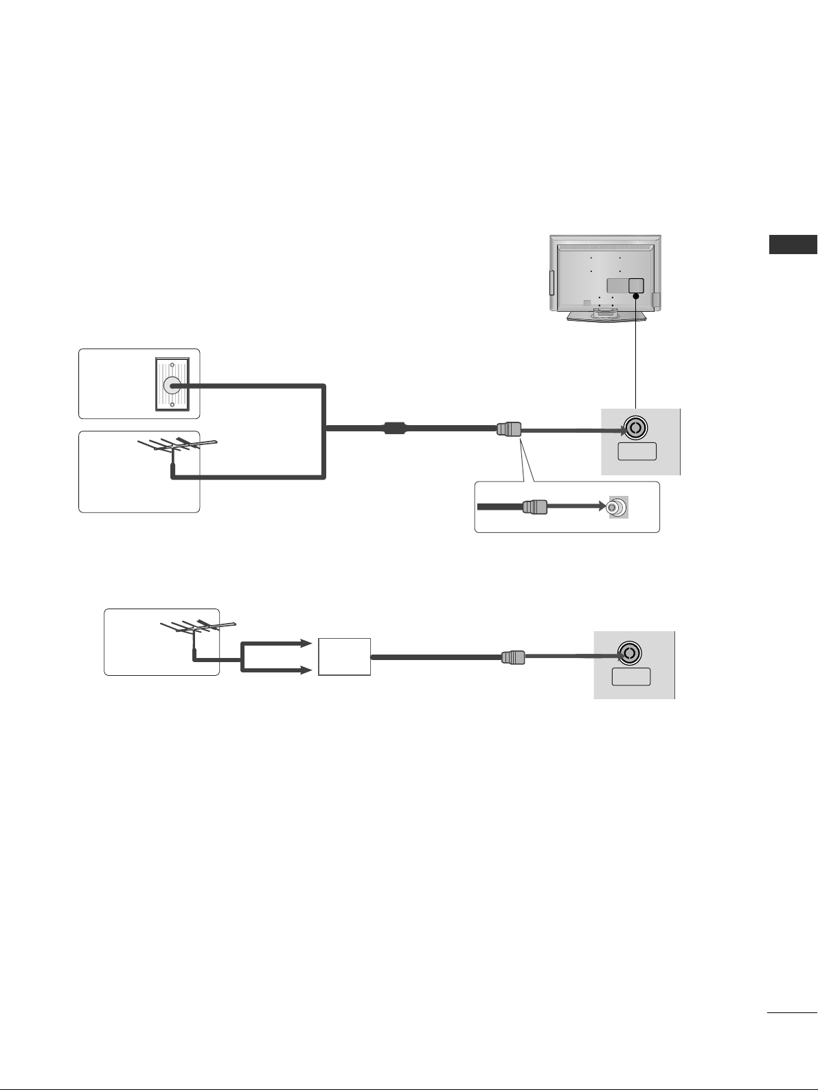
ANTENNA CONNECTION
■
For optimum picture quality, adjust antenna direction.
■
An antenna cable and converter are not supplied.
Multi-family Dwellings/Apartments
(Connect to wall antenna socket)
Single-family Dwellings /Houses
(Connect to wall jack for outdoor antenna)
Outdoor
Antenna
Wall
Antenna
Socket
RF Coaxial Wire (75 ohm)
Antenna
UHF
Signal
Amplifier
VHF
■
In poor signal areas,to get better picture quality, install a signal amplifier to the antenna as shown.
■
If signal needs to be split for two TVs,use an antenna signal splitter for connection.
■
To prevent the equipment damage, never plug in any power cords until you have finished connecting all equipment.
12
EXTERNAL EQUIPMENT SETUP
HDMI IN HDMI DVI IN
1
2
COMPONENT IN
AUDIO
VIDEO
HDMI IN HDMI DVI IN
HDMI/DVI IN
1
1 2
EXTERNAL EQUIPMENT SETUP
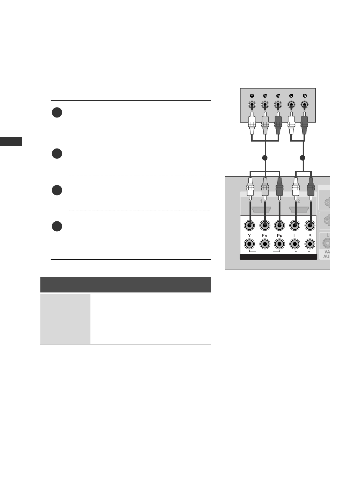
HD RECEIVER SETUP
When connecting with a component cable
Connect the video outputs (Y, PB, P
R
)
of the digital set
top box to the
CC OOMMPPOO NN EENNTT IINN VV IIDDEEOO
jacks on the
set.
Connect the audio output of the digital set-top box to
the
CC OOMMPPOO NN EENNTT IINN AA UUDDIIOO
jacks on the set.
Turn on the digital set-top box.
(
Refer to the owner’s manual for the digital set-top box.
)
Select Component1 input source with using the
IINNPPUUTT
button on the remote control.
If connected to
CC OOMMPPOO NN EENNTT IINN22
, select
Component2 input source.
2
3
4
1
Signal
480i
480p
720p
1080i
1080p
Component 1/2
Yes
Yes
Yes
Yes
Yes
HDMI1/DVI, HDMI2
No
Yes
Yes
Yes
Yes
■
To prevent the equipment damage, never plug in any power cords until you have finished connecting all equipment.
13
EXTERNAL EQUIPMENT SETUP
HDMI-DTV OUTPUT
HDMI IN HDMI DVI IN
1
2
COMPONENT IN
HDMI IN HDMI DVI IN
HDMI/DVI IN
1
HDMI IN HDMI DVI IN
HDMI IN HDMI/DVI IN
1 2
1
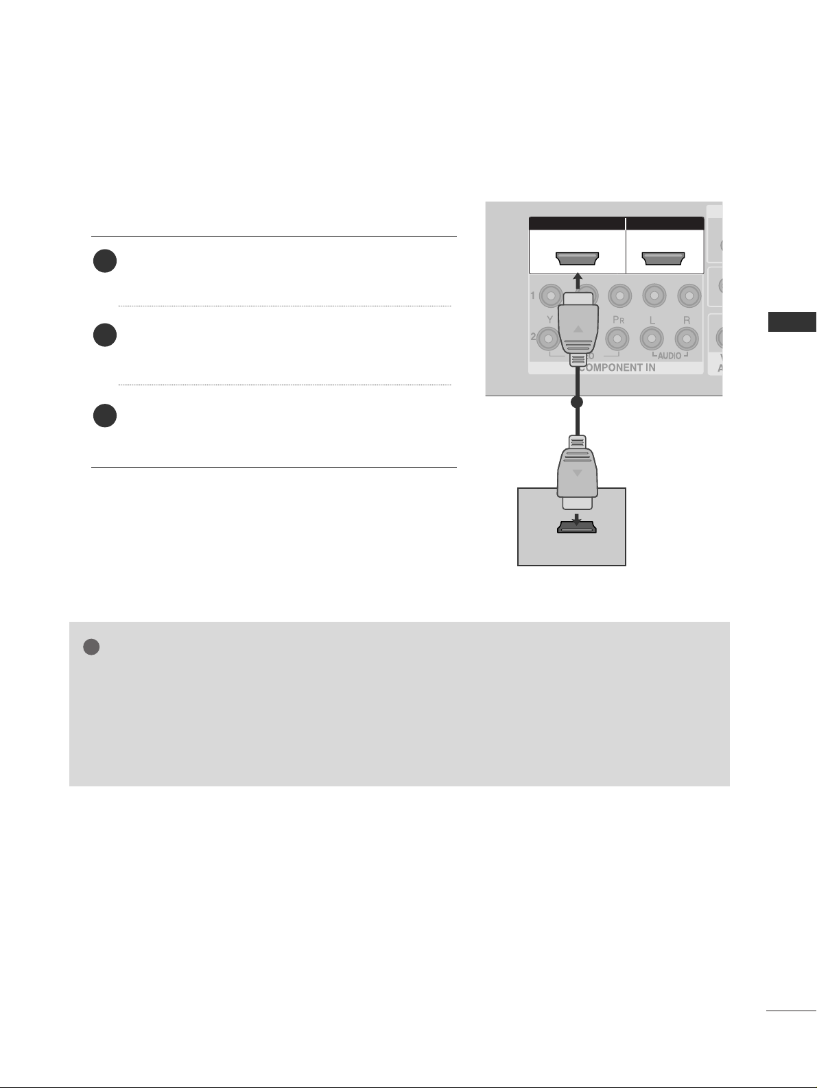
When connecting with a HDMI cable
Connect the HDMI output of the digital set-top box to
the
HHDDMM II// DDVVII IINN 11
or
HHDDMM II IINN 22
jack on the set.
Select
HDMI1/DVI or HDMI2 input source with using
the
IINNPP UUTT
button on the remote control.
Turn on the digital set-top box.
(
Refer to the owner’s manual for the digital set-top box.
)
2
3
1
GG
If the digital set-top box supports Auto HDMI function, the output resolution of the source device will
be automatically set to 1920x1080i/1080p.
GG
If the digital set-top box player does not support Auto HDMI, you need to set the output resolution
appropriately.
To get the best picture quality, adjust the output resolution of the source device to 1920x1080i/1080p.
NOTE
!
14
EXTERNAL EQUIPMENT SETUP
EXTERNAL EQUIPMENT SETUP
HDMI IN HDMI DVI IN
HDMI/DVI IN
1
AV IN 1AV IN 1 AV OUTAV OUT
AUDIO
(RGB/DVI)
RGB
(PC)
AUDIO
(RGB/DVI)
RGB(PC)
RGB IN
R
S
-2
3
2
C
(C
O
N
T
R
O
L
&
S
E
R
V
IC
E
)
L
/M
O
N
O
1
2
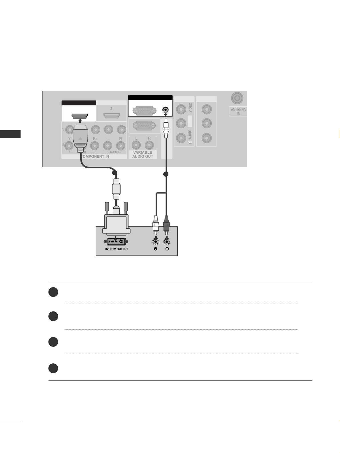
Connect the DVI output of the digital set-top box to the
HHDDMM II// DDVVII IINN 11
jack on the set.
Connect the audio output of the digital set-top box to the
AAUUDDIIOO((RRGG BB//DDVVII ))
jack on the set.
Turn on the digital set-top box. (Refer to the owner’s manual for the digital set-top box.
)
Select
HDMI1/DVI input source with using the
IINNPP UUTT
button on the remote control.
2
3
4
1
When connecting with a HDMI to DVI cable
15
EXTERNAL EQUIPMENT SETUP
HDMI IN HDMI IN HDMI DVI IN HDMI DVI IN
1
2
COMPONENT INCOMPONENT IN
AUDIO
VIDEO
AV IN 2
L/MONO
R
AUDIO
VIDEO
S-VIDEO
1 2
DVD SETUP
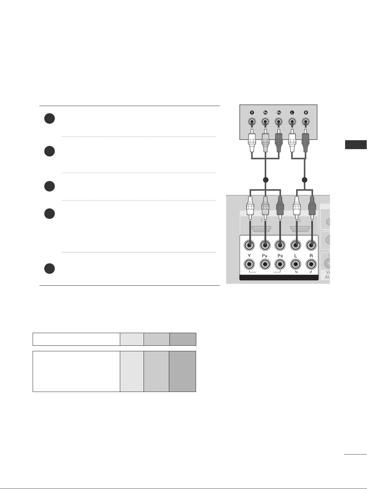
When connecting with a component cable
Component Input ports
To get better picture quality, connect a DVD player to the component input ports as shown below.
Component ports on the TV
YPB PR
Video output ports
on DVD player
Y
Y
Y
Y
P
B
B-Y
Cb
Pb
P
R
R-Y
Cr
Pr
Connect the video outputs (Y, PB, PR
)
of the DVD to the
CC OOMMPPOO NN EENNTT IINN VV IIDDEEOO
jacks on the set.
Connect the audio outputs of the DVD to the
CC OOMMPPOO--
NNEENNTT IINN AAUU DDIIOO
jacks on the set.
Turn on the DVD player, insert a DVD.
Select
Component
11
input source with using the
IINNPP UUTT
button on the remote control.
If connected to
CC OOMMPPOO NN EENNTT IINN22
, select
Component2
input source.
Refer to the DVD player's manual for operating instructions.
2
3
4
5
1
16
EXTERNAL EQUIPMENT SETUP
EXTERNAL EQUIPMENT SETUP
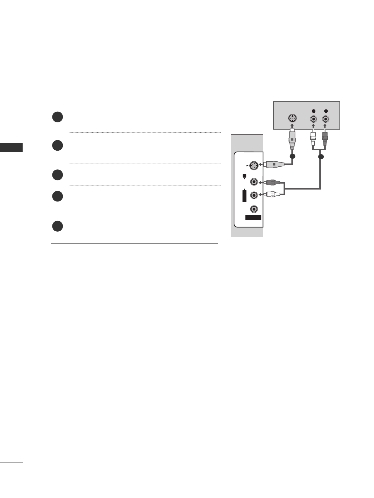
When connecting with an S-Video cable
Connect the S-VIDEO output of the DVD to the
SS --
VVII DDEEOO
input on the set.
Connect the audio outputs of the DVD to the
AAUU DD IIOO
input jacks on the set.
Turn on the DVD player, insert a DVD.
Select
AV 2 input source with using the
IINNPP UUTT
but-
ton on the remote control.
Refer to the DVD player's manual for operating
instructions.
2
3
4
5
1
L R
S-VIDEO
AUDIO
AV IN 2AV IN 2
L/L /MONOMONO
R
AUDIOAUDIO
VIDEOVIDEO
S-VIDEOS-VIDEO
1
2
17
EXTERNAL EQUIPMENT SETUP
HDMI IN HDMI DVI IN
1
2
COMPONENT IN
HDMI IN HDMI IN HDMI DVI IN HDMI DVI IN
HDMI IN HDMI IN HDMI/DVI IN HDMI/DVI IN
1 2
AV IN 2
L/MONO
R
AUDIO
VIDEO
S-VIDEO
HDMI IN HDMI DVI IN
1
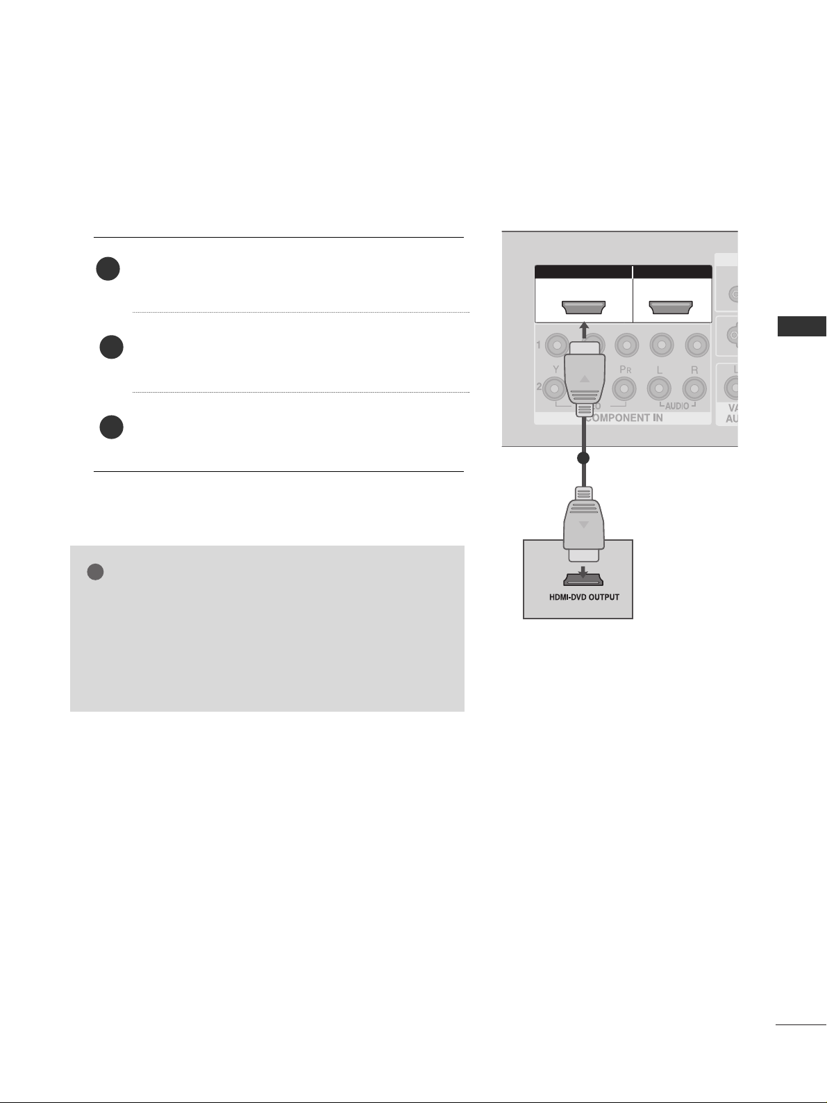
When connecting HDMI cable
Connect the HDMI output of the DVD to the
HHDDMM II// DDVVII IINN 11
or
HHDDMM II IINN 22
jack on the set.
Select
HDMI1/DVI or HDMI2 input source with
using the
IINNPP UUTT
button on the remote control.
Refer to the DVD player's manual for operating
instructions.
1
GG
If the DVD supports Auto HDMI function, the DVD output
resolution will be automatically set to 1920x1080i/1080p.
GG
If the DVD player does not support Auto HDMI, you need
to set the output resolution appropriately.
To get the best picture quality, adjust the output resolution
of the DVD to 1920x1080i/1080p.
NOTE
!
2
3
18
EXTERNAL EQUIPMENT SETUP
EXTERNAL EQUIPMENT SETUP
L/ MONO
R
AUDIO
S-VIDEO
ANTENNA
IN
OUTPUT
SWITCH
ANT IN
R
S-VIDEO VIDEO
ANT OUT
L
(CONTROL&SERVICE)
AV IN 1AV IN 1 AV OUTAV OUT
L/MONO
Wall Jack
Antenna
1
2
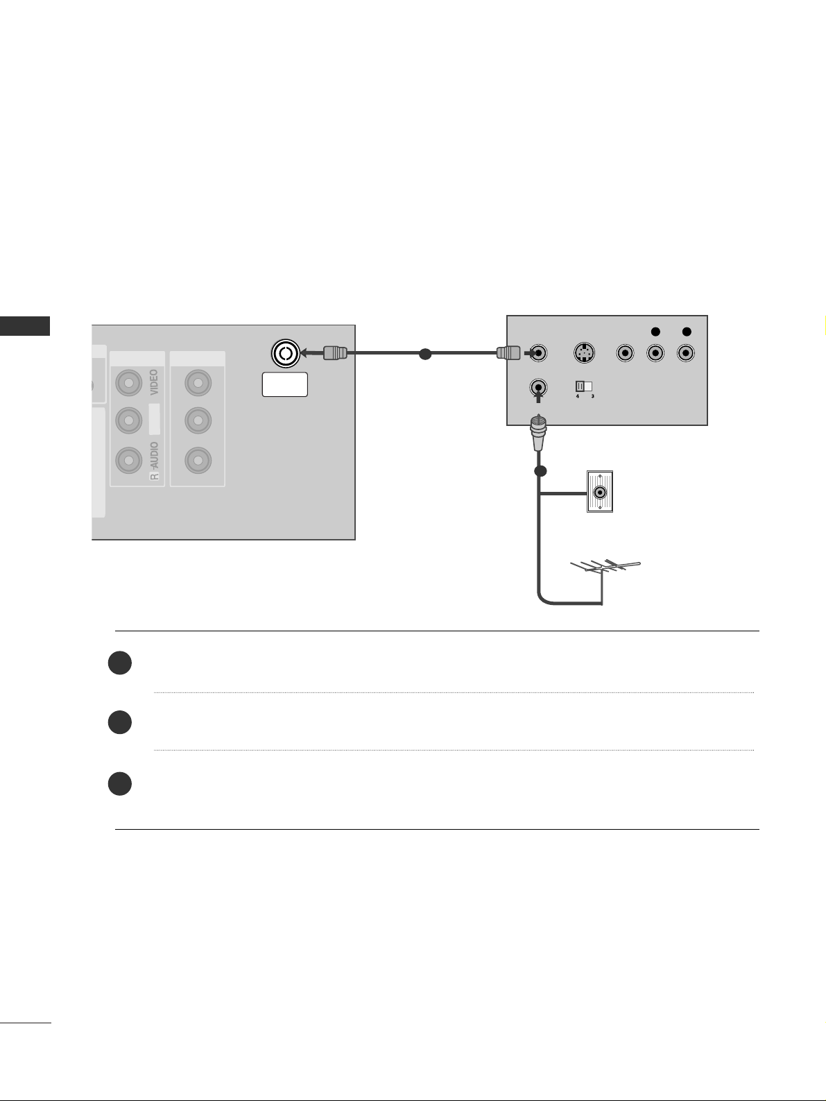
VCR SETUP
When connecting with an antenna
■
To avoid picture noise (interference), leave an adequate distance between the VCR and TV.
■
Typically a frozen still picture from a VCR. If the 4:3 picture format is used; the fixed images on the sides of
the screen may remain visible on the screen.
Connect the
AANNTT OOUUTT
socket of the VCR to the
AANNTTEENNNNAA II NN
socket on the set.
Connect the antenna cable to the
AANNTT II NN
socket of the VCR.
Press the
PPLLAA YY
button on the VCR and match the appropriate programme between the TV and VCR for
viewing.
1
2
2
3
1
19
EXTERNAL EQUIPMENT SETUP
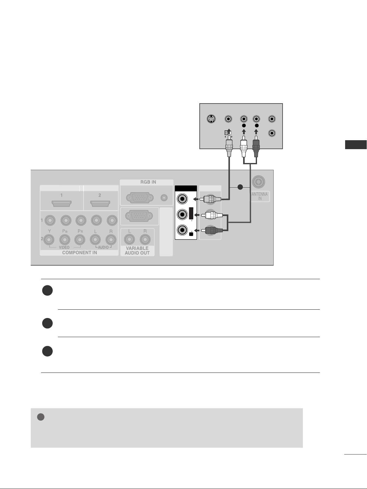
When connecting with a RCA cable
AV IN 1AV IN 1 AV OUTAV OUT
AV IN 2
L/ MONO
R
AUDIO
VIDEO
S-VIDEO
AV IN 1
HDMI IN HDMI DVI IN
AUDIO
(RGB/DVI)
RGB
(PC)
RS-232C
(CONTROL&SERVICE)
L/MONO
R
AUDIOAUDIO
VIDEOVIDEO
L
R
S-VIDEO
VIDEO
OUTPUT
SWITCH
ANT IN
ANT OUT
Connect the
AAUU DD IIOO/VVII DDEEOO
jacks between TV and VCR. Match the jack colors (Video = yellow,
Audio Left = white, and Audio Right = red)
Insert a video tape into the VCR and press PLAY on the VCR. (Refer to the VCR owner’s manual.
)
Select
AV 1 input source using the
IINNPP UUTT
button on the remote control.
If connected to
AAVV II NN 22
, select
AV 2 input source.
1
2
3
GG
If you have a mono VCR, connect the audio cable from the VCR to the
AAUUDD IIOO LL// MM OO NN OO
jack
of the set.
NOTE
!
1
20
EXTERNAL EQUIPMENT SETUP
EXTERNAL EQUIPMENT SETUP
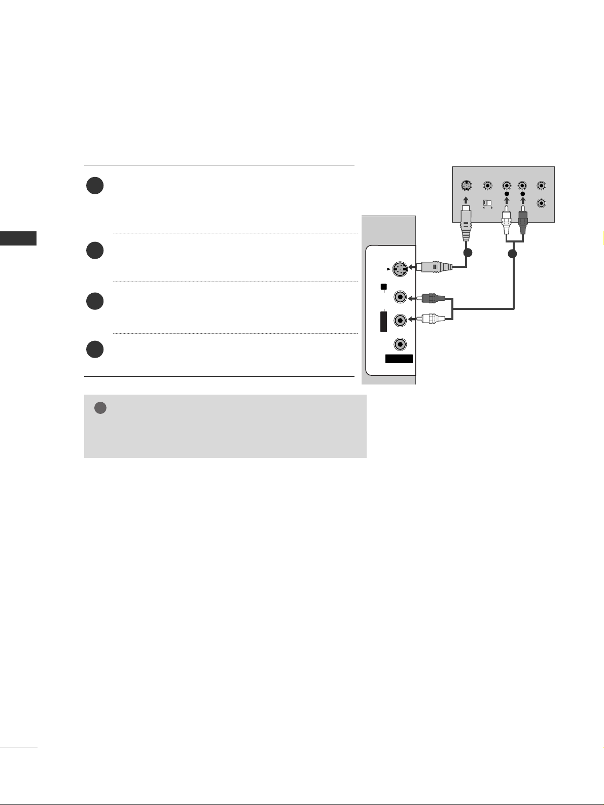
GG
If both S-VIDEO and VIDEO sockets have been connected to
the S-VHS VCR simultaneously, only the S-VIDEO can be
received.
NOTE
!
L
R
S-VIDEO
VIDEO
OUTPUT
SWITCH
ANT IN
ANT OUT
AV IN 2
L/MONO
R
AUDIOAUDIO
VIDEOVIDEO
S-VIDEO
When connecting with an S-Video cable
Connect the S-VIDEO output of the VCR to the
SS --
VVII DDEEOO
input on the set. The picture quality is
improved; compared to normal composite (RCA cable)
input.
Connect the audio outputs of the VCR to the
AAUU DD IIOO
input jacks on the set.
Insert a video tape into the VCR and press PLAY on
the VCR. (Refer to the VCR owner’s manual.)
Select
AV 2 input source with using the
IINNPP UUTT
but-
ton on the remote control.
2
3
4
1
1
2
21
EXTERNAL EQUIPMENT SETUP
AV IN 2
L/MONO
R
AUDIOAUDIO
VIDEOVIDEO
S-VIDEO
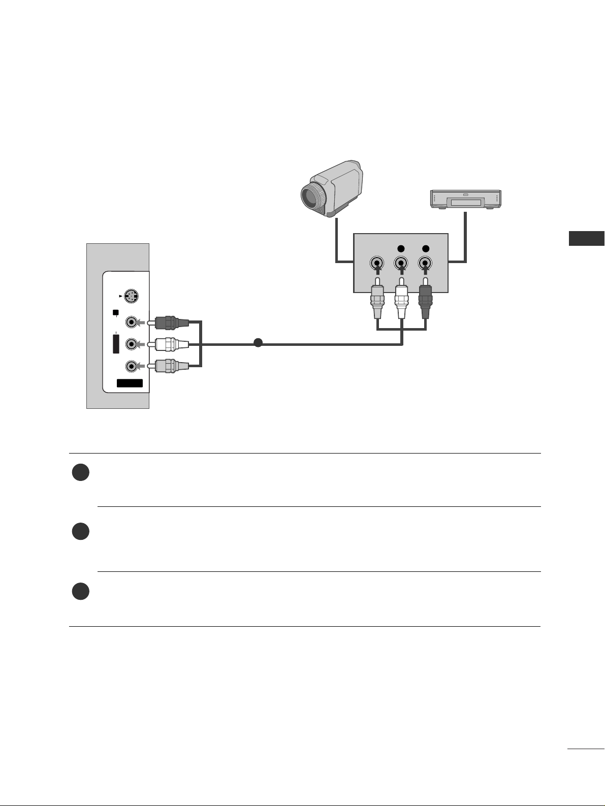
L R
VIDEO
Camcorder
Video Game Set
1
OTHER A/V SOURCE SETUP
Connect the
AAUU DD IIOO/VVII DDEEOO
jacks between TV and external equipment. Match the jack colors
.
(
Video = yellow, Audio Left = white, and Audio Right = red
)
Select AV 2 input source with using the
IINNPP UUTT
button on the remote control.
If connected to
AAVV II NN 11
, select
AV 1 input source.
Operate the corresponding external equipment.
Refer to external equipment operating guide.
1
2
3
22
EXTERNAL EQUIPMENT SETUP
AUDIO
(RGB/DVI)
RGB
(PC)
AUDIO
(RGB/DVI)
RGB
(PC)
RGB IN
HDMI IN HDMI DVI IN
R
S
-2
3
2
C
(C
O
N
T
R
O
L
&
S
E
R
V
IC
E
)
AV IN 1AV IN 1 AV OUTAV OUT
RGB OUTPUT
AUDIO
L/MONO
R
AUDIO
V
ID
E
O
L
/M
O
N
O
L/MONO
R
AUDIO
V
ID
E
O
1
2
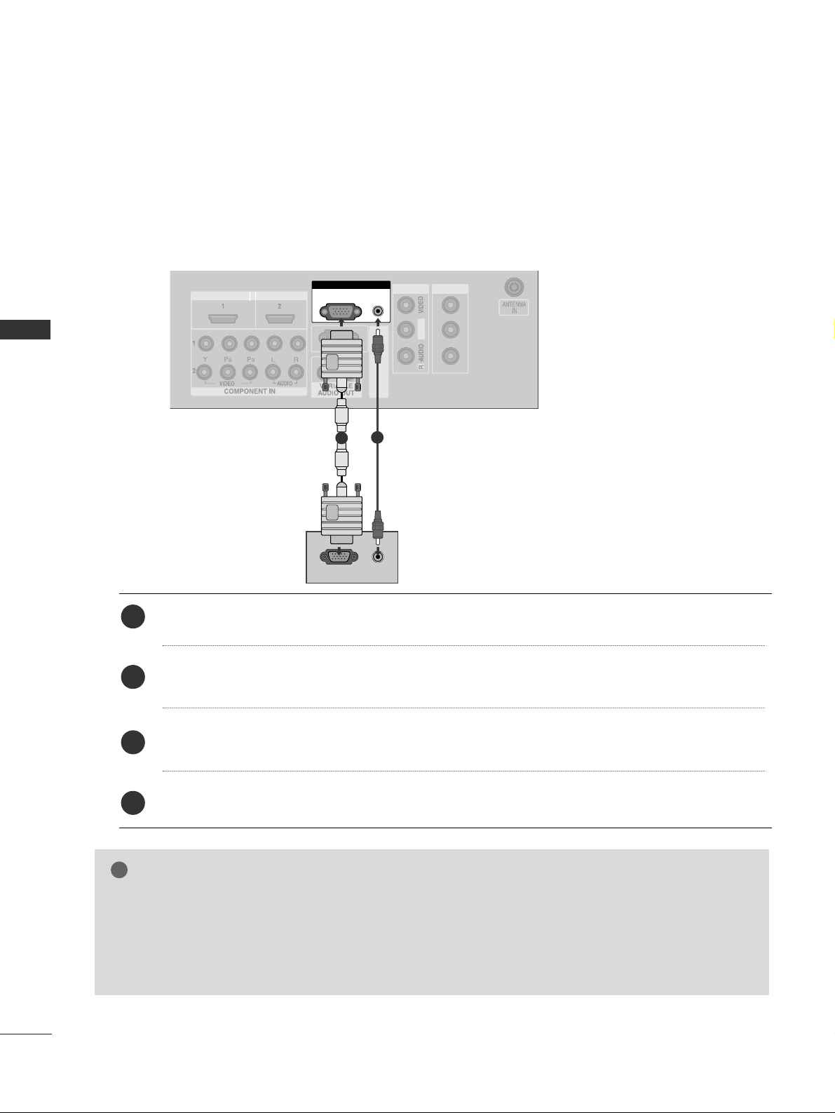
PC SETUP
This TV provides Plug and Play capability, meaning that the PC adjusts automatically to the TV's settings.
When connecting with a D-sub 15 pin cable
Connect the RGB output of the PC to the
RRGG BB
((
PP CC
))
jack on the set.
Connect the PC audio output to the
AAUUDDIIOO((RRGG BB//DDVVII ))
jack on the set.
Turn on the PC and the set.
Select
RGB PC input source with using the
IINNPPUUTT
button on the remote control.
2
3
4
1
GG
Check the image on your TV. There may be noise associated with the resolution, vertical pattern, contrast or
brightness in PC mode. if noise is present, change the PC output to another resolution, change the refresh rate to
another rate or adjust the brightness and contrast on the VIDEO menu untio the picture is clear. If the refresh rate
of the PC graphic card can not be changed, change the PC graphic card or consult the manufacturer of the PC
graphic card.
NOTE
!
EXTERNAL EQUIPMENT SETUP
23
EXTERNAL EQUIPMENT SETUP
RGB IN
HDMI IN HDMI DVI IN
HDMI IN HDMI DVI IN
HDMI/DVI IN
1
AV IN 1AV IN 1 AV OUTAV OUT
AUDIO
(RGB/DVI)
RGB
(PC)
AUDIO
(RGB/DVI)
RGB(PC)
RGB IN
R
S
-2
3
2
C
(C
O
N
T
R
O
L
&
S
E
R
V
IC
E
)
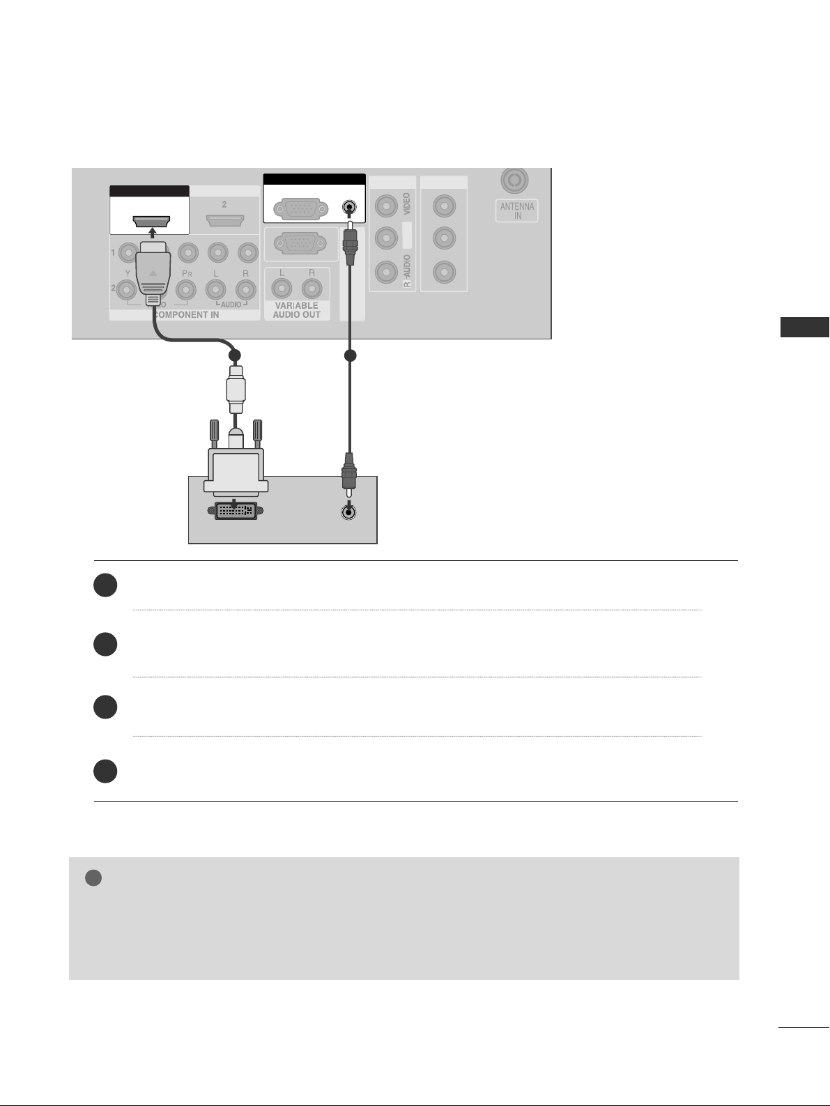
DVI-PC OUTPUT
AUDIO
L/ MONO
R
A
U
D
IO
VIDEO
L/ MONO
R
A
U
D
IO
VIDEO
L/M
O
N
O
1
2
Connect the DVI output of the PC to the
HHDDMM II// DDVVII IINN 11
jack on the set.
Connect the PC audio output to the
AAUUDDIIOO((RRGG BB//DDVVII ))
jack on the set.
Turn on the PC and the set.
Select
HDMI1/DVI input source with using the
IINNPP UUTT
button on the remote control.
2
3
4
1
When connecting with a HDMI to DVI cable
GG
HDMI2 source does not support DVI source.
GG
If the PC has a DVI output and no HDMI output, a separated audio connection is necessary.
GG
If the PC does not support Auto DVI, you need to set the output resolution appropriately, To get the best picture quality, adjust the output resolution of PC graphics card’s output resolution to 1024x768,60Hz.
NOTE
!
24
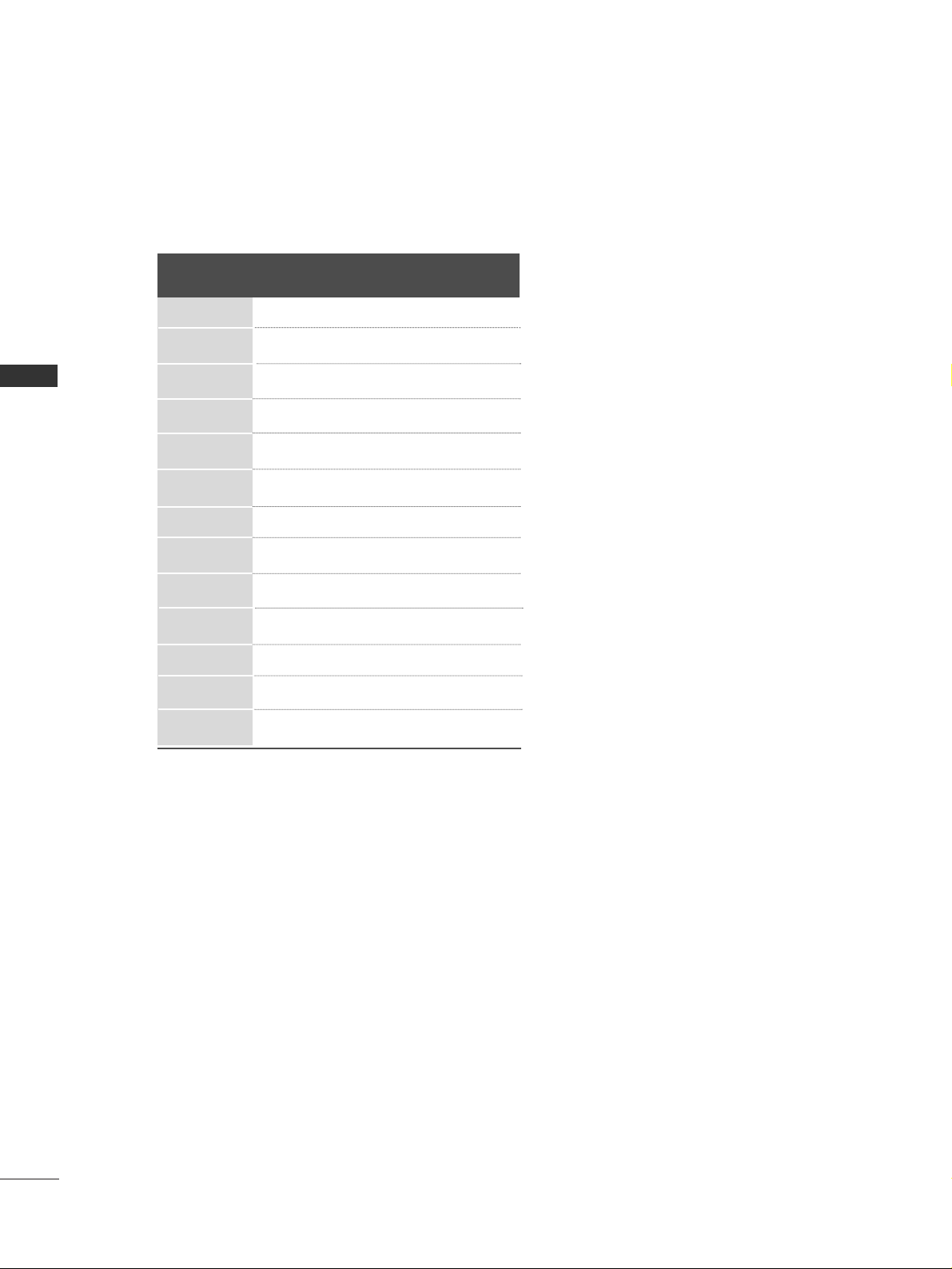
EXTERNAL EQUIPMENT SETUP
Resolution
720x400
640x480
800x600
1024x768
1280x768
1280x960
(HDMI[PC]only)
1360x768
1366x768
1280x1024
1400x1050
(RGB[PC]only)
1600x1200
1920x1080
1920x1200
Supported Display Resolution (RGB[PC]/HDMI[PC]mode)
Horizontal Vertical
Frequency(kHz) Frequency(Hz)
31.5 70.1
31 . 5 59 . 9
37.9 60 .3
48.4 60.0
47.8 59.9
59.7 59.9
47.7 59.8
47.7 60 .0
63.7 59.5
65.3 60.0
75.0 60.0
66.6 60.0
74.0 60.0
EXTERNAL EQUIPMENT SETUP

25
EXTERNAL EQUIPMENT SETUP
NOTE
!
GG
To get the the best picture quality, adjust the PC graphics card to 1920x1080, 60Hz.
GG
Depending on the graphics card, DOS mode may not work if a HDMI to DVI Cable is in use.
GG
When Source Devices connected with HDMI Input, output TV SET Resolution (480p, 720p, 1080i) and
TV SET Display fit EIA/CEA-861-B Specification to Screen. If not, refer to the Manual of HDMI Source
Devices or contact your service center.
GG
If the HDMI Source Device is not connected to the Cable or if there is a poor cable connection, "No signal" is displayed in the HDMI Input. In this case, that Video Resolution is not supported.
GG
Avoid keeping a fixed image on the screen for a long period of time. The fixed image may become permanently imprinted on the screen.
GG
The synchronization input form for Horizontal and Vertical frequencies is separate.
GG
When you use too long RGB-PC cable, there might be a noise on the screen. We recommend using under
5m of the cable. It provides the best picture quality.
26
EXTERNAL EQUIPMENT SETUP
EXTERNAL EQUIPMENT SETUP
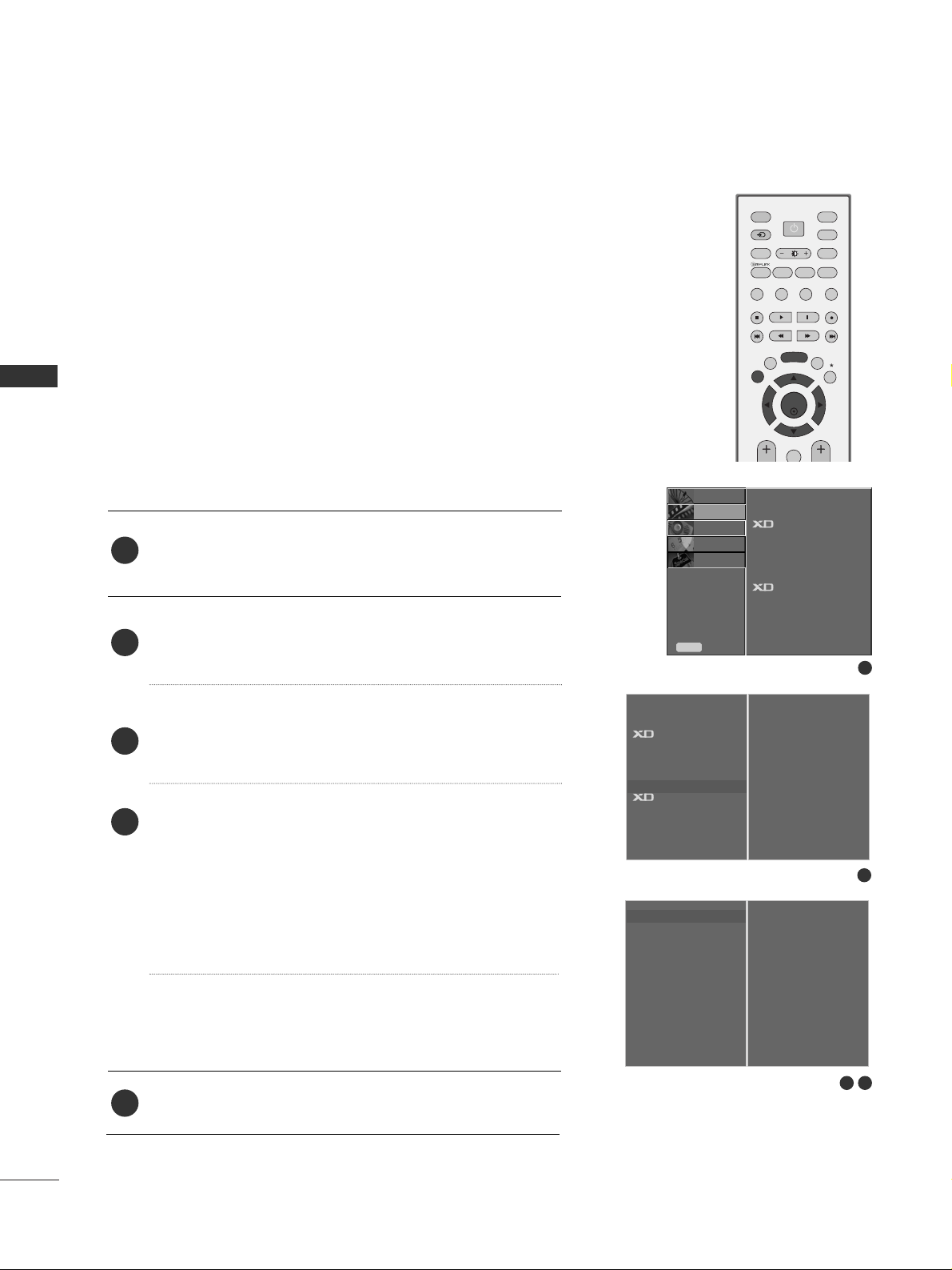
Press the
MMEE NN UU
button and then use
DD
//
EE
button to
select the
PICTURE menu.
Press the
GG
button and then use
DD
//
EE
button to select
Screen.
Press the
GG
button and then use
DD
//
EE
button to select
Auto Config..
Press the
GG
button to start Auto Config..
• When
AAuuttoo ccoonnffiigg..
has finished, OK will be shown on
screen.
• If the position of the image is still not correct, try Auto
adjustment again.
• If picture needs to be adjusted more after Auto adjust-
ment in RGB (PC), you can adjust the
Manual Config..
Press the
EEXXIITT
button to return to TV viewing.
Automatically adjusts picture position and minimizes image
shaking.After adjustment, if the image is still not correct, your
set is functioning properly but needs further adjustment.
AAuu ttoo ccoo nn ffii gguurree
This function is for the automatic adjustment of the screen
position, clock, and phase. The displayed image will unstable for
a few seconds while the auto configuration is in progress.
1
2
3
4
5
Screen Setup for PC mode
Auto Configure (RGB [PC] mode only)
1
3 4
2
SETUP
O
PICTURE
O
Prev.
Menu
AUDIO
O
TIME
O
OPTION
O
To Set
Auto Config. G
Manual Config.
XGA Mode
Reset
To S et
Picture Mode
Colour Temperature
Advanced
Aspect Ratio
Picture Reset
Screen
Demo
Picture Mode
Colour Temperature
Advanced
Aspect Ratio
Picture Reset
Screen
G
Demo
OK
INPUT MODE
TVTV
DVD
RATIO
EXIT
PIP
SLEEP
LIST
Q.VIEW
I/II
MENU
VCR
PIP PR- PIP PR+
PIP INPUT
POWER
FAV
SIMPLINK
INPUT
SWAP
 Loading...