

LG Electronics 37LC2RR, 42LC2RR, 42PC1RR, 50PC1RR User Manual

PP//NNOO:: 3388228899UU00556644FF ((00661111--RREE VV0033))
ENGLISH
DEUTSCH
FRANÇAIS
ITALIANO
3377LLCC22RRRR
**
4422PPCC11RRRR
**
4422LLCC22RRRR
**
5500PPCC11RRRR
**
PPlleeaassee rreeaadd IInnffoorrmmaattiioonn
M
aannuuaall iinncclluuddeedd
ttooggeetthheerr bbeeffoorree rreeaaddiinngg tthhiiss mmaannuuaall aanndd ooppeerr--
aattiinngg yyoouurr sseett..
Retain it for future reference.
Record model number and serial number of the set.
See the label attached on the back cover and quote
this information to your dealer when you require service.
Model number :
Serial number :
LCD TV
LCD TV MODELS PLASMA TV MODELS
PLASMA TV
OWNER’s MANUAL
Downloaded From TV-Manual.com Manuals

Downloaded From TV-Manual.com Manuals
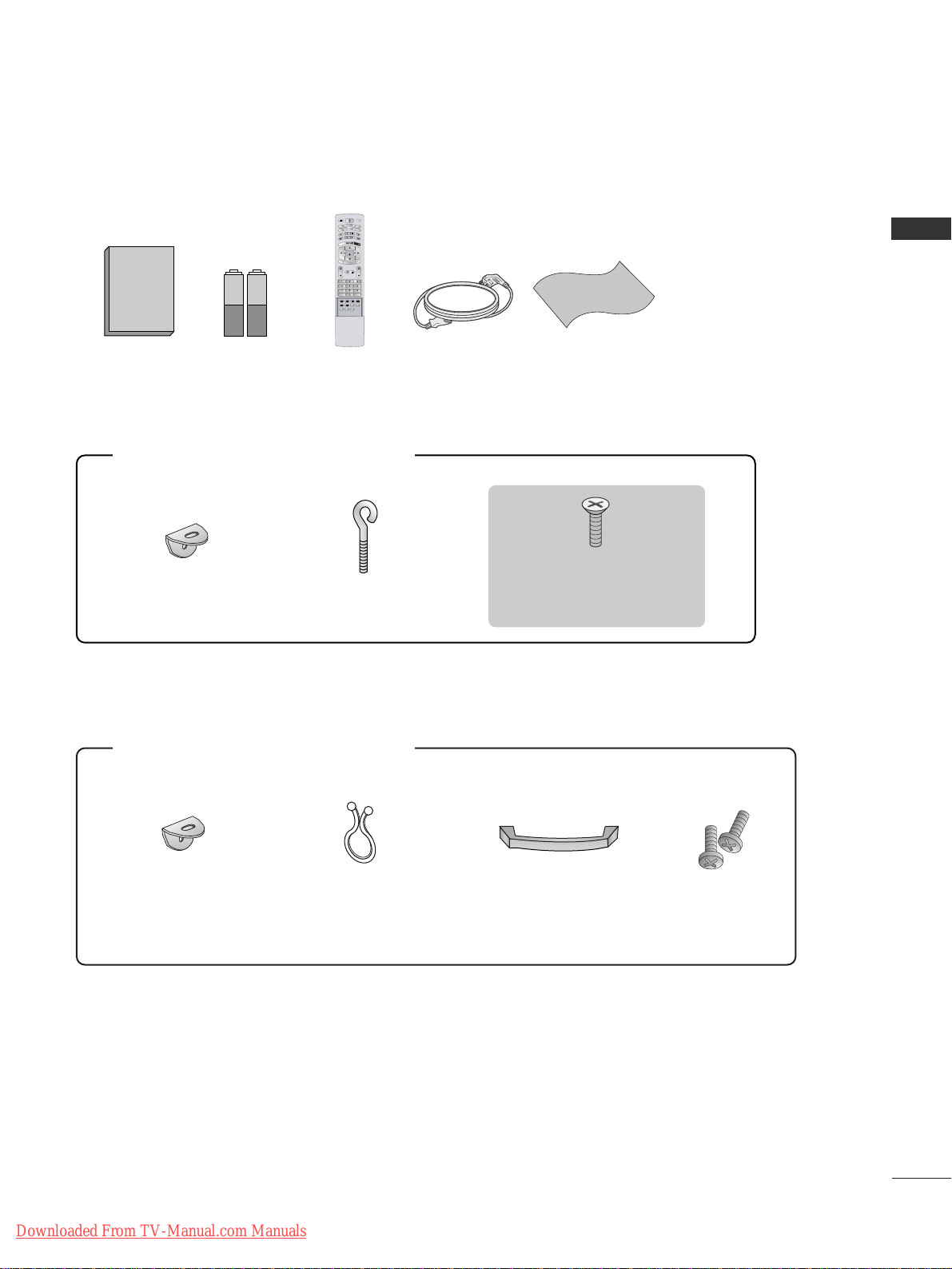
ACCESSORIES
1
ACCESSORIES
2-Wall brackets
2-eye-bolts
FFoorr 4422 PPCC 11RRRR
**,,
55 00PPCC11RRRR
**
2-bolts for stand assembly
(Refer p.11)
This feature is not available
for all models.
FFoorr 3377 LLCC22 RR RR
**,,
44 22LLCC22 RR RR
**
2-TV brackets
2-Wall brackets
2-bolts
Cable
Management
Twister Holder
Arrange the wires
with the twister holder.
Ensure that the following accessories are included with your set. If an accessory is missing, please contact the
dealer where you purchased the set.
Owner's Manual
Owner’s Manual Batteries
MODE
INPUT
T
V
DVD
V
C
R
A
U
D
I
O
PI
P
P
R
-
P
IP
P
R
+
S
W
A
P
PI
P IN
PUT
S
T
B
M
E
N
U
MUTE
SIZE POSITION INDEX
SLEEP
FAV
I/II
PIP ARC
Q.VIEWLIST
TEXT
OK
VOL PR
MULTIMEDIA
POWER
CABLE
HOLD
REVEAL
?
TIME
E
X
I
T
M
A
R
K
L
I
V
E
T
V
TIME
SHIFT
TIME
SHIFT
Remote Control Power Cord Polishing Cloth
Polish the screen with the cloth
(Option)
Slightly wipe stained spot on the
exterior only with the cleansing
cloths for the product exterior if
there is stain or fingerprint on
surface of the exterior.
Do not wipe roughly when
removing stain. Please be cautious of that excessive power may
cause scratch or discoloration.
Downloaded From TV-Manual.com Manuals

CONTENTS
2
CONTENTS
Accessories . . . . . . . . . . . . . . . . . . . . . . . . . . . . . . . . . . . . . . . . . . . . 1
INTRODUCTION
Controls / Connection Options
. . . . . . . . . . . . . . . . . . 4-7
Remote Control Key Functions
. . . . . . . . . . . . . . . . . . . . . 8-9
Home Menu
. . . . . . . . . . . . . . . . . . . . . . . . . . . . . . . . . . . . . . . . . . 10
INSTALLATION
Unfolding The Base Stand
. . . . . . . . . . . . . . . . . . . . . . . . . . . 11
Basic connection
. . . . . . . . . . . . . . . . . . . . . . . . . . . . . . . . . 12 - 13
How to join the set assembly to the wall to protect the
set tumbling
. . . . . . . . . . . . . . . . . . . . . . . . . . . . . . . . . . . . . . . . . . . 14
Stand installation
. . . . . . . . . . . . . . . . . . . . . . . . . . . . . . . . . . . . . 15
CONNECTIONS & SETUP
Antenna Connection . . . . . . . . . . . . . . . . . . . . . . . . . . . . . . . . . 16
VCR Setup
. . . . . . . . . . . . . . . . . . . . . . . . . . . . . . . . . . . . . . . . 17 - 18
External Equipment Connections
. . . . . . . . . . . . . . . . . . . . 19
DVD Setup
. . . . . . . . . . . . . . . . . . . . . . . . . . . . . . . . . . . . . . .
20-21
STB(SET-TOP BOX) Setup
. . . . . . . . . . . . . . . . . . . . . . 22 -23
PC Setup
. . . . . . . . . . . . . . . . . . . . . . . . . . . . . . . . . . . . . . . . . 24 - 26
BASIC OPERATION
Turning the set on . . . . . . . . . . . . . . . . . . . . . . . . . . 27
Volume Adjustment . . . . . . . . . . . . . . . . . . . . . . . . . 27
Programme Selection . . . . . . . . . . . . . . . . . . . . . . . . 28
On-Screen Menu Language Selection (option) . . . 28
SPECIAL FUNCTIONS
DVR (Digital Video Recorder
)
TimeShift
. . . . . . . . . . . . . . . . . . . . . . . . . . . . . . . . . . . . . . . . . . . . . 29
Progressing the Timeshift function
. . . . . . . . . . . . . .30-31
Recording
. . . . . . . . . . . . . . . . . . . . . . . . . . . . . . . . . . . . . . . . .32 -33
Watching & Record
. . . . . . . . . . . . . . . . . . . . . . . . . . . . . . . . . . .34
Recorded TV
. . . . . . . . . . . . . . . . . . . . . . . . . . . . . . . . . . . . . . . . . .35
Recorded program Selection and Popup Menu
.35- 36
Playing recorded programs
. . . . . . . . . . . . . . . . . . . . . . . . . . .36
Using the remote control
. . . . . . . . . . . . . . . . . . . . . . . . . . . .37
Manual Recording
. . . . . . . . . . . . . . . . . . . . . . . . . . . . . . . . . . . .38
Scheduled List
. . . . . . . . . . . . . . . . . . . . . . . . . . . . . . . . . . . . . . . .39
Video Quality
. . . . . . . . . . . . . . . . . . . . . . . . . . . . . . . . . . . . . . . .
39
Format hard disk . . . . . . . . . . . . . . . . . . . . . . . . . . . . . . . . . . . .40
PIP/POP/Twin Picture
PIP (Picture-In-Picture) Feature . . . . . . . . . . . . . . . . 41
Watching PIP . . . . . . . . . . . . . . . . . . . . . . . . . . . . . . 41
Adjusting PIP Transparency (PIP mode only) . . . . . 41
Programme Selection for Sub Picture . . . . . . . . . . . 42
Adjusting the screen for the PIP . . . . . . . . . . . . . . . 42
Selecting an Input Signal Source for the PIP . . . . . 42
Sub Picture Size Adjustment (PIP mode only) . . . . 42
Moving the PIP (PIP mode only) . . . . . . . . . . . . . . . 42
Swapping between main and sub pictures . . . . . . . 43
POP (Picture-out-of-Picture: Channel Scan) . . . . . 43
TELETEXT
Teletext Language Selection (option) . . . . . . . . . . . . . . . 44
Switch on/off
. . . . . . . . . . . . . . . . . . . . . . . . . . . . . . . . . . . . . . . . 44
SIMPLE Text (option)
. . . . . . . . . . . . . . . . . . . . . . . . . . . . . . . . 45
TOP Text (option)
. . . . . . . . . . . . . . . . . . . . . . . . . . . . . . . . . . . 45
FASTEXT
. . . . . . . . . . . . . . . . . . . . . . . . . . . . . . . . . . . . . . . . . . . . . 45
Special Teletext Functions
. . . . . . . . . . . . . . . . . . . . . . . . . . . 46
Downloaded From TV-Manual.com Manuals

CONTENTS
3
TV MENU
On Screen Menus Selection and Adjustment . . . . . . . 47
Setting up TV stations
Auto programme Tuning
. . . . . . . . . . . . . . . . . . . . . . . . . . . . . 48
Manual programme Tuning
. . . . . . . . . . . . . . . . . . . . . . . . . . 49
Fine tuning
. . . . . . . . . . . . . . . . . . . . . . . . . . . . . . . . . . . . . . . . . . . 50
Assigning a station name
. . . . . . . . . . . . . . . . . . . . . . . . . . . . 51
Booster (option)
. . . . . . . . . . . . . . . . . . . . . . . . . . . . . . . . . . . . . 52
Programme edit
. . . . . . . . . . . . . . . . . . . . . . . . . . . . . . . . . . . . . . 53
Favourite programme
. . . . . . . . . . . . . . . . . . . . . . . . . . . . . . . . 54
Calling the programme table
. . . . . . . . . . . . . . . . . . . . . . . . 55
Picture Menu Options
PSM (Picture Status Memory) . . . . . . . . . . . . . . . . . . . . . . 56
CSM (Colour Status Memory)
. . . . . . . . . . . . . . . . . . . . . . 57
Manual Colour Temperature Control (CSM - User option)
. . . . . .
58
XD Function . . . . . . . . . . . . . . . . . . . . . . . . . . . . . . . . . . . . . . . . . . 59
sRGB Function . . . . . . . . . . . . . . . . . . . . . . . . . . . . . 60
ACM (Active Colour Management) . . . . . . . . . . . . . 61
Manual Picture Control . . . . . . . . . . . . . . . . . . . . . . 62
Sound Menu Options
SSM (Sound Status Memory) . . . . . . . . . . . . . . . . . . . . . . . 63
AVL (Auto Volume Leveler)
. . . . . . . . . . . . . . . . . . . . . . . . . . 64
Adjusting Sound Control
. . . . . . . . . . . . . . . . . . . . . . . . . . . . 65
TV Speaker
. . . . . . . . . . . . . . . . . . . . . . . . . . . . . . . . . . . . . . . . . . . 65
Stereo/Dual Reception
. . . . . . . . . . . . . . . . . . . . . . . . . . . . . . 66
NICAM Reception (option)
. . . . . . . . . . . . . . . . . . . . . . . . . 67
Sound Output Selection
. . . . . . . . . . . . . . . . . . . . . . . . . . . . 67
Time Menu Options
Setting the Clock . . . . . . . . . . . . . . . . . . . . . . . . . . . 68
Setting the On/Off Time . . . . . . . . . . . . . . . . . . . . . 69
Auto Sleep
. . . . . . . . . . . . . . . . . . . . . . . . . . . . . . . . . . . . . . . . . . . 70
Sleep Timer
. . . . . . . . . . . . . . . . . . . . . . . . . . . . . . . . . . . . . . . . . . 70
Special Menu Options
Child Lock
. . . . . . . . . . . . . . . . . . . . . . . . . . . . . . . . . . . . . . . . . . . . 71
ISM Method (Image Sticking Minimization)
. . . . . . . . 72
Low Power
. . . . . . . . . . . . . . . . . . . . . . . . . . . . . . . . . . . . . . . . . . . . 73
XD Demo
. . . . . . . . . . . . . . . . . . . . . . . . . . . . . . . . . . . . . . . . . . . . . 73
Index (option)
. . . . . . . . . . . . . . . . . . . . . . . . . . . . . . . . . . . . . . . . 74
Screen Menu Options
Auto Config. . . . . . . . . . . . . . . . . . . . . . . . . . . . . . . 75
Manual Config. . . . . . . . . . . . . . . . . . . . . . . . . . . . . 76
Selecting Wide XGA/VGA mode . . . . . . . . . . . . . . . 77
Setting Picture Format . . . . . . . . . . . . . . . . . . . . . . . 78
Cinema . . . . . . . . . . . . . . . . . . . . . . . . . . . . . . . . . . . 79
NR (Noise Reduction) . . . . . . . . . . . . . . . . . . . . . . . 80
Initializing (Reset to original factory settings) . . . . 80
APPENDIX
External Control Device Setup . . . . . . . . . . . . . .81-87
IR Codes . . . . . . . . . . . . . . . . . . . . . . . . . . . . . . .88-89
Programming the Remote . . . . . . . . . . . . . . . . . . . . 90
Programming Codes . . . . . . . . . . . . . . . . . . . . . 91-94
Troubleshooting Checklist . . . . . . . . . . . . . . . . . 95-96
Maintenance . . . . . . . . . . . . . . . . . . . . . . . . . . . . . . 97
Product Specifications . . . . . . . . . . . . . . . . . . . 98-99
Downloaded From TV-Manual.com Manuals
INTRODUCTION
4
INTRODUCTION
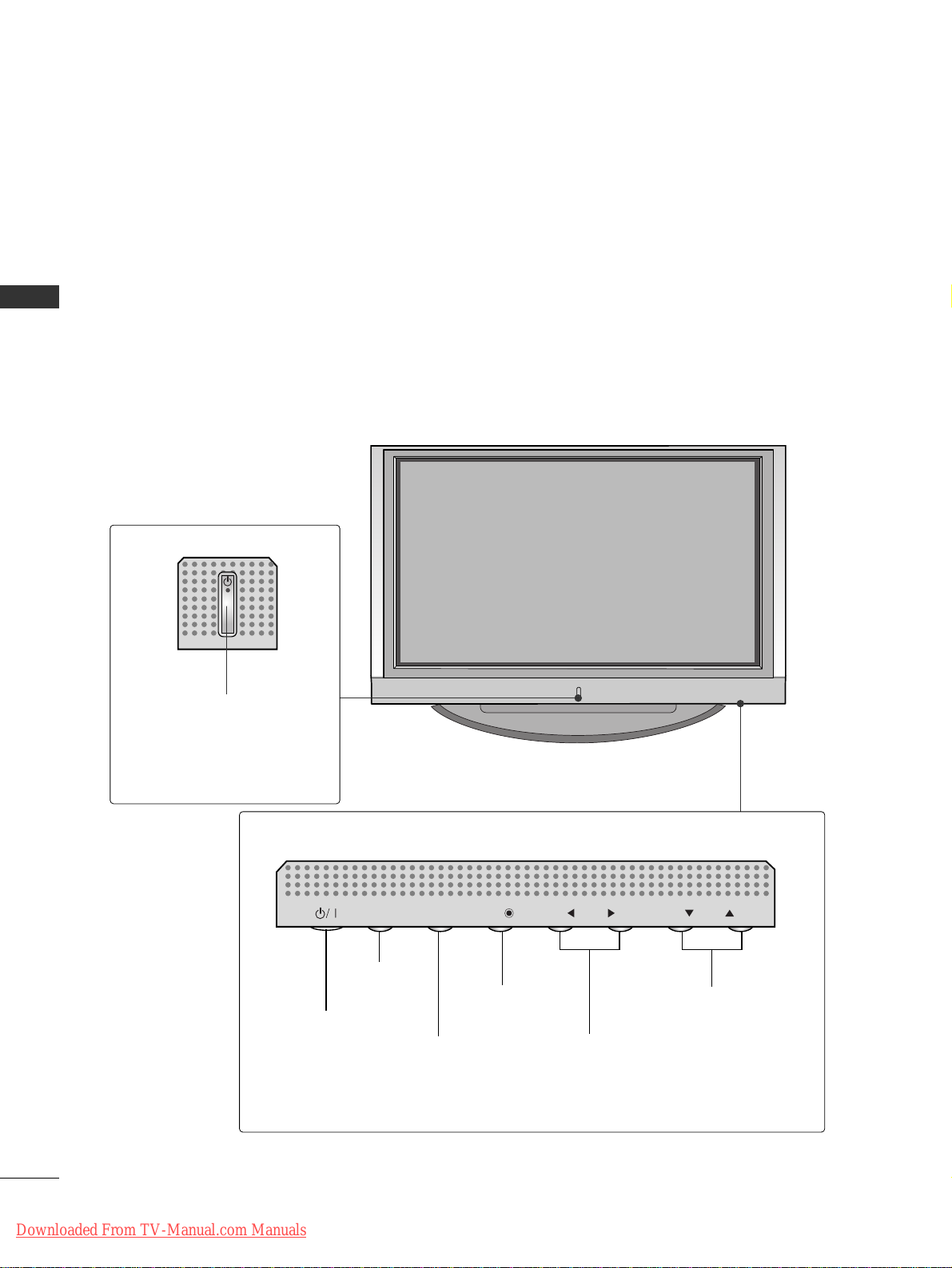
CONTROLS
This manual explains the features available on the 42PC1RR
*,
50PC1RR* set.
A
This is a simplified representation of a front panel. Here shown may be somewhat different from your set.
Front Panel Controls
PROGRAMME Buttons
VOLUME Buttons
MENU Button
OK Button
INPUT Button
POWER Button
PR
VOL
OK
MENU
INPUT
Power/Standby Indicator
• illuminates red in standby mode.
• illuminates white when the set is
switched on.
• illuminates orange when manual
recording in stanby mode.
PR
VOL
OK
MENU
INPUT
Downloaded From TV-Manual.com Manuals
INTRODUCTION
5
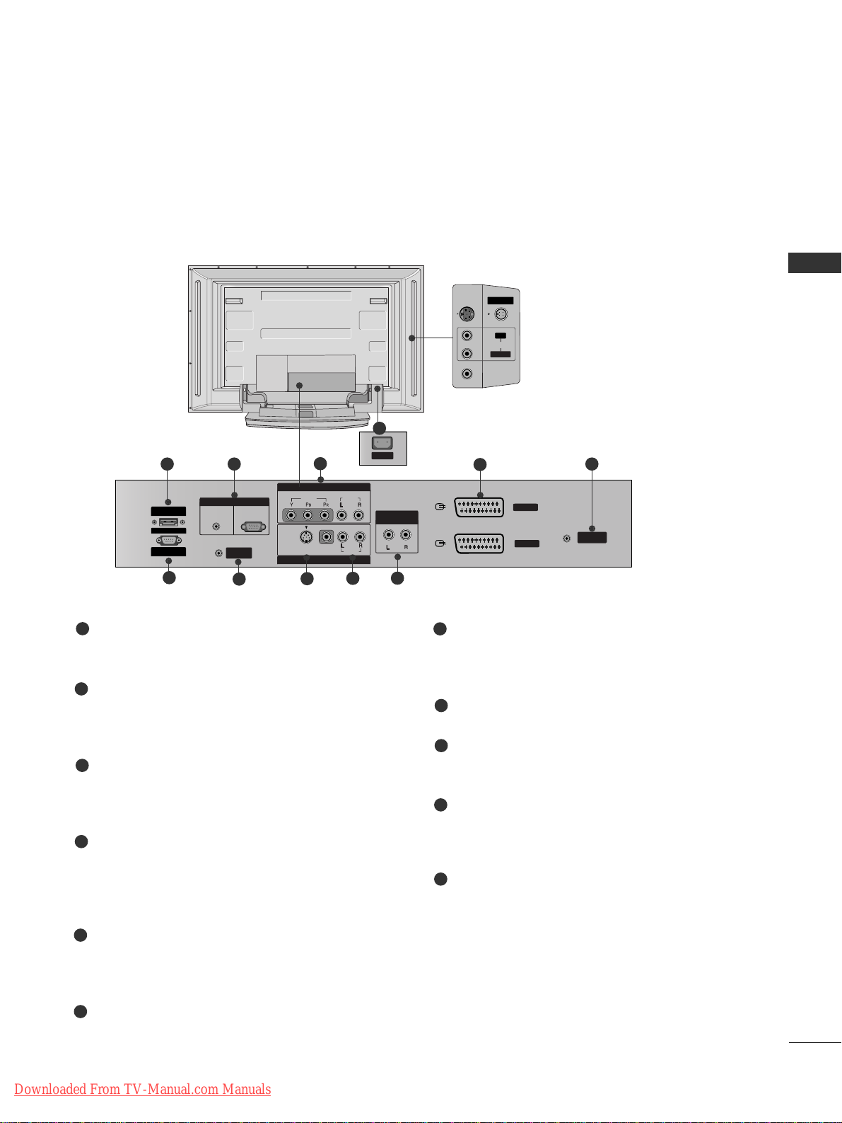
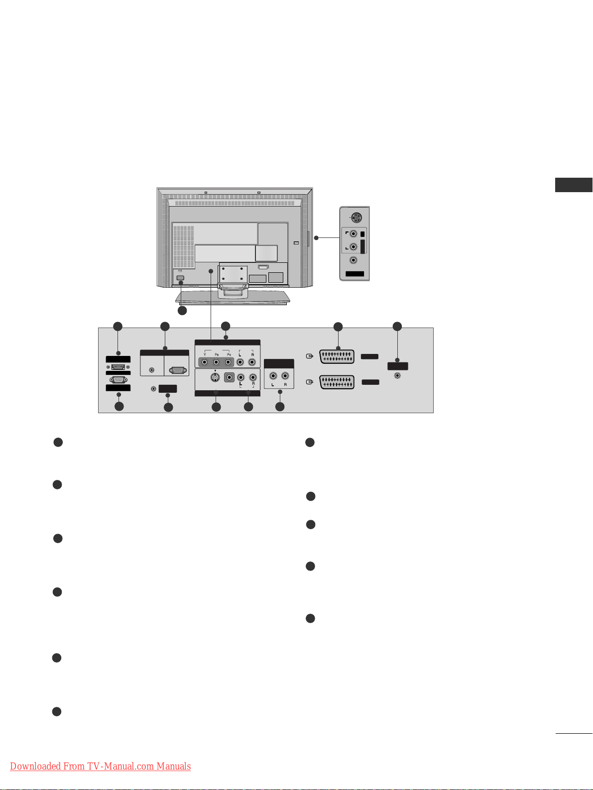
CONNECTION OPTION
This is the back panel of 42PC1RR
*
,
50PC1RR*sets.
HDMI/DVI Input
Connect a HDMI signal to HDMI/DVI.
RGB/Audio Input
Connect the monitor output from a PC/DTV to
the appropriate input port.
Component Input
Connect a component video/audio device to
these jacks.
Power Cord Socket
This set operates on an AC power. The voltage is
indicated on the Specifications page. Never
attempt to operate the set on DC power.
Euro Scart Socket (AV1/AV2)
Connect scart socket input or output from an
external device to these jacks.
Antenna Input
RS-232C Input
(CONTROL&SERVICE)
Port
Connect the serial port of the control devices to
the RS-232C jack.
Remote Control Port
S-Video Input
Connect S-Video out from an S-VIDEO device.
Audio/Video Input
Connect audio/video output from an external
device to these jacks.
Variable Audio Output
Connect an external amplifier or add a subwoofer
to your surround sound system.
1
2
3
4
5
6
7
8
9
10
11
ANTENNA
IN
AV 1
AV 2
AUDIO OUT
VARIABLE
RGB IN
COMPONENTCOMPONENT IN
VIDEOVIDEO
AUDIO
AV IN 4
L/MONO
R
AUDIOAUDIO
VIDEOVIDEO
MONO
( )
AUDIO
VIDEO
S-VIDEO
AV IN 3
RGB
(PC/DTV)(PC/DTV)
AUDIO
(RGB/DVI)
CONTROL IN
REMOTE
S-VIDEOS-VIDEO
AC IN
HDMI/
DVI IN
RS-232C IN
(CONTROL
& SERVICE)
Back Connection Panel
S-VIDEO Input
Connect S-Video out from an S-VIDEO
device.
AUDIO Input
Connections are available for listening
stereo sound from an external device.
VIDEO Input
Connects the video signal from a video
device.
4
11
9
8
7
10
3
21
5
6
Downloaded From TV-Manual.com Manuals
INTRODUCTION
6
INTRODUCTION
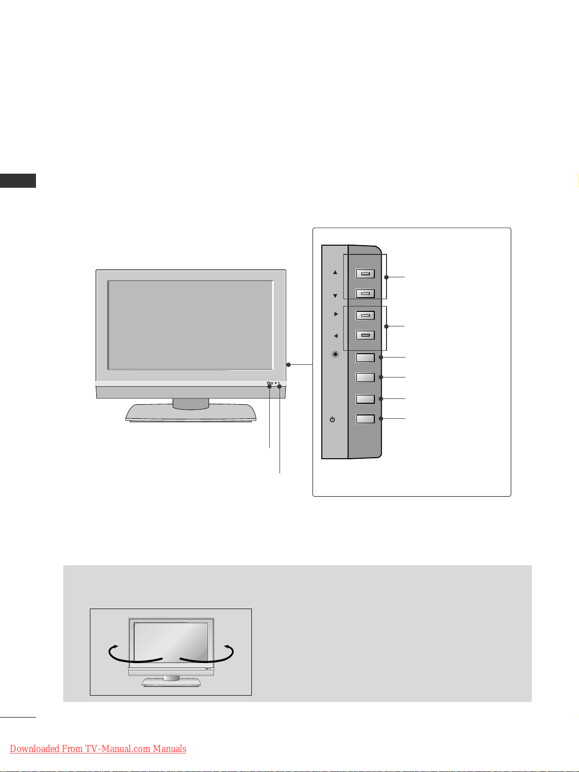
CONTROLS
This is the front panel of models
3377LLCC22RRRR
*
,
4422LLCC22RRRR
*
sets.
■
This is a simplified representation of a front panel. Here shown may be somewhat different from your set.
PR
VOL
OK
MENU
INPUT
R
/I
Remote Control Sensor
Power/Standby Indicator
• illuminates red in standby mode.
• illuminates white when the set is switched on.
• illuminates orange when manual recording in
stanby mode.
PROGRAMME Buttons
VOLUME Buttons
OK Button
MENU Button
INPUT Button
POWER Button
<Front Panel >
<Side Panel >
- The set can be conveniently swivelled on its stand 30°
to the left or right to provide the optimum viewing
angle.
Swivel Stand (42LC2RR *only)
R
30° 30°
- This feature is not available for all models.
Downloaded From TV-Manual.com Manuals
INTRODUCTION
7
CONNECTION OPTION
This is the back panel of models
3377LLCC22RRRR
*
,
4422LLCC22RRRR
*
sets.
HDMI/DVI Input
Connect a HDMI signal to HDMI/DVI.
RGB/Audio Input
Connect the monitor output from a PC/DTV to
the appropriate input port.
Component Input
Connect a component video/audio device to
these jacks.
Power Cord Socket
This set operates on an AC power. The voltage is
indicated on the Specifications page. Never
attempt to operate the set on DC power.
Euro Scart Socket (AV1/AV2)
Connect scart socket input or output from an
external device to these jacks.
Antenna Input
RS-232C Input
(CONTROL&SERVICE)
Port
Connect the serial port of the control devices to
the RS-232C jack.
Remote Control Port
S-Video Input
Connect S-Video out from an S-VIDEO device.
Audio/Video Input
Connect audio/video output from an external
device to these jacks.
Variable Audio Output
Connect an external amplifier or add a subwoofer
to your surround sound system.
1
2
3
4
5
6
7
8
9
10
11
AC IN
AV IN 4
AUDIOAUDIOVIDEOVIDEO
S-VIDEOS-VIDEO
L/MONO
R
ANTENNA
IN
AV 1
AV 2
AUDIO OUT
VARIABLEARIABLE
RGB IN
COMPONENTCOMPONENT IN
VIDEO
AUDIO
MONO
( )
AUDIO
VIDEO
S-VIDEO
AV IN 3
RGB
(PC/DTV)
AUDIO
(RGB/DVI)
CONTROL IN
REMOTE
HDMI/
DVI IN
RS-232C IN
(CONTROL
& SERVICE)
Back Connection Panel
S-VIDEO Input
Connect S-Video out from an SVIDEO device.
AUDIO Input
Connections are available for listening stereo sound from an
external device.
VIDEO Input
Connects the video signal from a
video device.
4
11
9
8
7
10
3
21
5
6
Downloaded From TV-Manual.com Manuals
INTRODUCTION
8
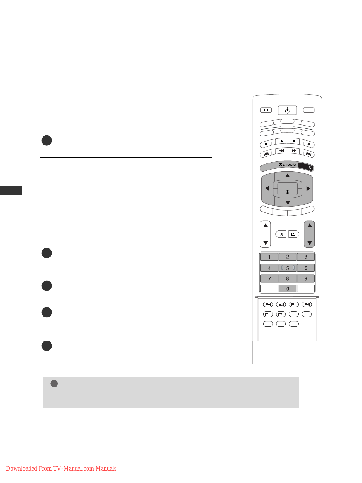
INTRODUCTION
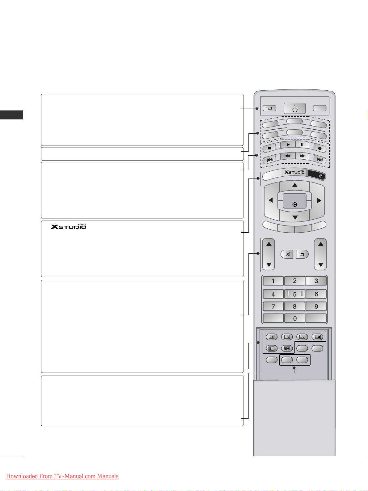
REMOTE CONTROL KEY FUNCTIONS
When using the remote control, aim it at the remote control sensor on the set.
There maybe a defect in consecutive operation of remote control in a specified brightness according to this set.
MODE
INPUT
TV
DVD
V
C
R
A
U
D
IO
PIP P
R
-
P
IP
P
R
+
SWAP
PIP INPUT
S
T
B
M
EN
U
MUTE
SIZE POSITION INDEX
SLEEP
FAV
I/II
PIP ARC
Q.VIEWLIST
TEXT
OK
VOL PR
MULTIMEDIA
POWER
CABLE
HOLD
REVEAL
?
TIME
EXIT
MARK
LIVE TV
TIME
SHIFT
TIME
SHIFT
POWER
INPUT
MULTIMEDIA
MODE
VCR BUTTONS
MARK
LIVE TV
MENU
EXIT
VOL
DD/ EE
(Volume Up/Down)
PR
DD/ EE
(Programme
Up/Down)
MUTE
TEXT
ARC
I/II
switches the set on from standby or off to standby.
Selects the TV, AV, Component, RGB or HDMI/DVI modes.
switches the set on from standby.
Selects the Component, RGB or HDMI/DVI modes.
switches the set on from standby.
Selects another device.
Controls a video cassette recorder.
These buttons are used for X Studio.
For further details, see the ‘X Studio’ section.
Selects the wanted functions.
In TV, AV1, AV2, S-Video2, AV3, AV4 modes, screen
returns to the live programme. (Refer to p.37)
Brings up the Home menu.
Displays on screen menus one by one.
Exits the current menu.
Memorizes menu changes.
Clears all on-screen displays and returns to TV viewing
from any menu.
Increases/decreases sound level.
Select a programme.
Switchs the set on from standby.
Switches the sound on or off.
These buttons are used for teletext.
For further details, see the ‘Teletext’ section.
Note : In teletext mode, the PIP PR +/-, SWAP and PIP
INPUT buttons are used for teletext function.
Changes the picture format.
Selects the language during dual language broadcast.
Selects the sound output.
Downloaded From TV-Manual.com Manuals
INTRODUCTION
9
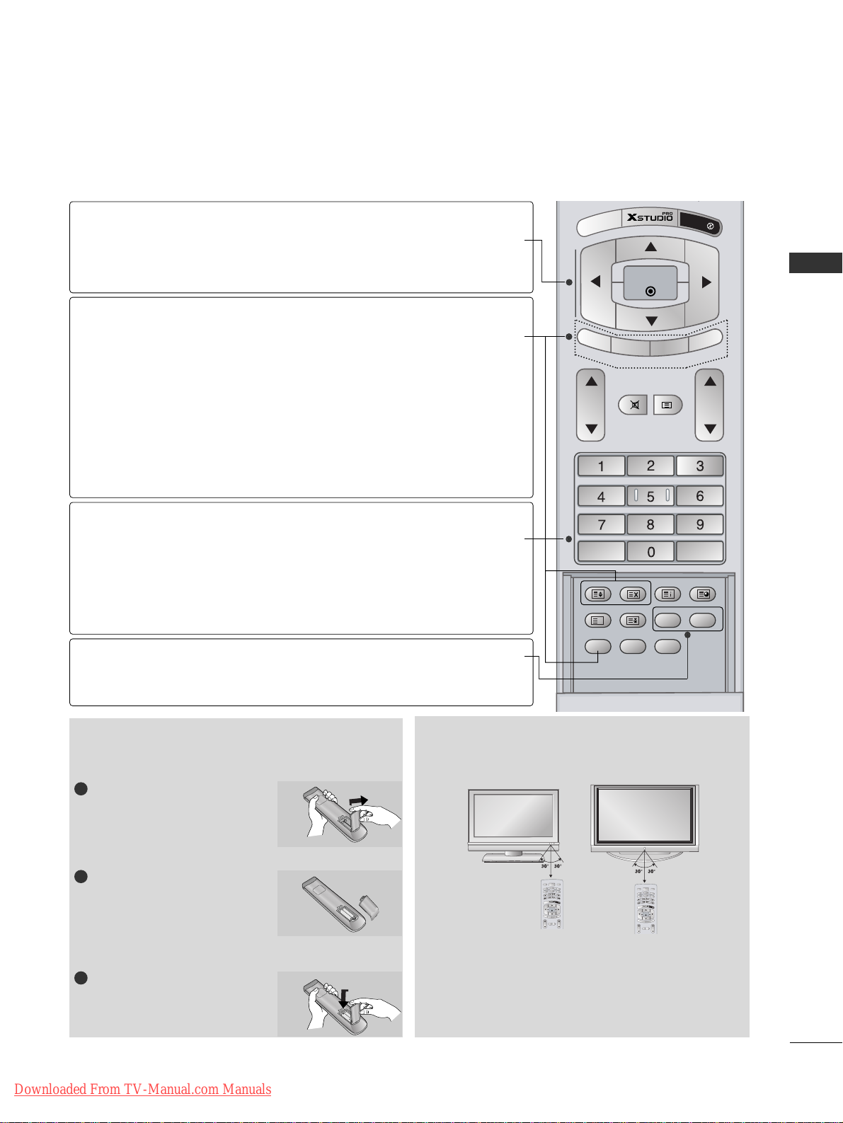
Installing Batteries
■
Use a remote control 7 meter distance and 30
degree (left/right)within the receiving unit scope.
■
Dispose of used batteries in a recyclebin to preserve environment.
Remote control effective range
REMOTE CONTROL KEY FUNCTIONS
P
IP
P
R -
P
IP
P
R
+
SWAP
PIP IN
PU
T
M
ENU
MUTE
SIZE POSITION INDEX
SLEEP
FAV
I/II
PIP ARC
Q.VIEWLIST
TEXT
OK
VOL PR
HOLD
REVEAL
?
TIME
EXIT
IVE TV
TIME
SHIFT
TIME
SHIFT
OK
DD/ EE
or
FF/ GG
(TIME SHIFT)
PIP
PIP PR +/-
SWAP
PIP INPUT
SIZE
POSITION
NUMBER buttons
LIST
Q.VIEW
SLEEP
FAV
accepts your selection or displays the
current mode.
Adjusts menu settings.
Selects menu item.
Switches the sub picture on or off.
Selects PIP , POP or DW modes.
Selects a programme for the sub picture.
Alternates between main and sub picture.
Selects the input mode for the sub picture.
Adjusts the sub picture size.
Moves the sub picture to
DD/ EE
or FF/ GGdirection.
Selects a programme.
Selects numbered items in a menu.
Switchs the set on from standby.
Displays the programme table.
Returns to the previously viewed programme.
Sets the sleep timer.
Selects a favourite programme.
Open the battery compartment cover on the back side.
Insert two batteries in correct
polarity (+ with +, - with -).
Don’t mix old or used batteries
with new ones.
Close the cover.
1
2
3
Downloaded From TV-Manual.com Manuals
MULTIMEDIA
INPUT
POWER
DVD
V
C
R
V
T
MODE
CABLE
S
O
I
T
D
B
U
A
M
A
R
K
L
I
V
E
T
V
E
X
U
I
N
T
E
M
OK
TIME
TIME
SHIFT
SHIFT
PIP PR -
T
U
P
N
I
P
I
P
P
I
P
P
P
R
A
+
W
S
MUTE
TEXT
VOL PR
INPUT
V
T
O
I
D
U
A
U
N
E
M
TIME
SHIFT
PIP PR -
VOL PR
MULTIMEDIA
POWER
DVD
V
C
R
MODE
CABLE
S
T
B
M
A
R
K
L
I
V
E
T
V
E
X
I
T
OK
TIME
SHIFT
T
U
P
IN
P
I
P
P
I
P
P
P
R
A
+
W
S
MUTE
TEXT
INTRODUCTION
10
INTRODUCTION
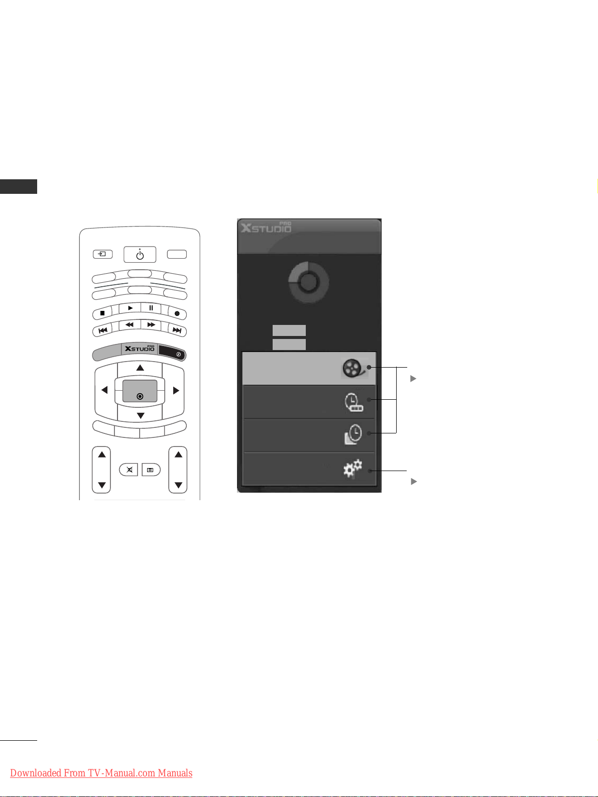
HOME MENU
This menu is a contents guide.
In Home Menu, you enter the Recorded list of DVR, Manual Rec, Scheduled List or
TV Menu.
MODE
INPUT
T
V
DVD
VCR
AUDIO
P
IP
P
R
-
PIP PR +
SW
A
P
P
IP
IN
P
U
T
STB
MENU
OK
VOL PR
MULTIMEDIA
CABLE
EXIT
MARK
LIVE TV
TIME
SHIFT
TIME
SHIFT
POWER
MUTE
TEXT
DVR
pp..2299
TV Menu
pp..4477
Home
Free Space
3h 19m
High
Normal 5h 24m
Manual Rec.
Recorded TV
Scheduled List
TV Menu
Downloaded From TV-Manual.com Manuals
INSTALLATION
11
INSTALLATION
UNFOLDING THE BASE STAND (42PC1RR
*
)
■
This feature is not available for all models.
Figures shown here may be slightly different from your set.
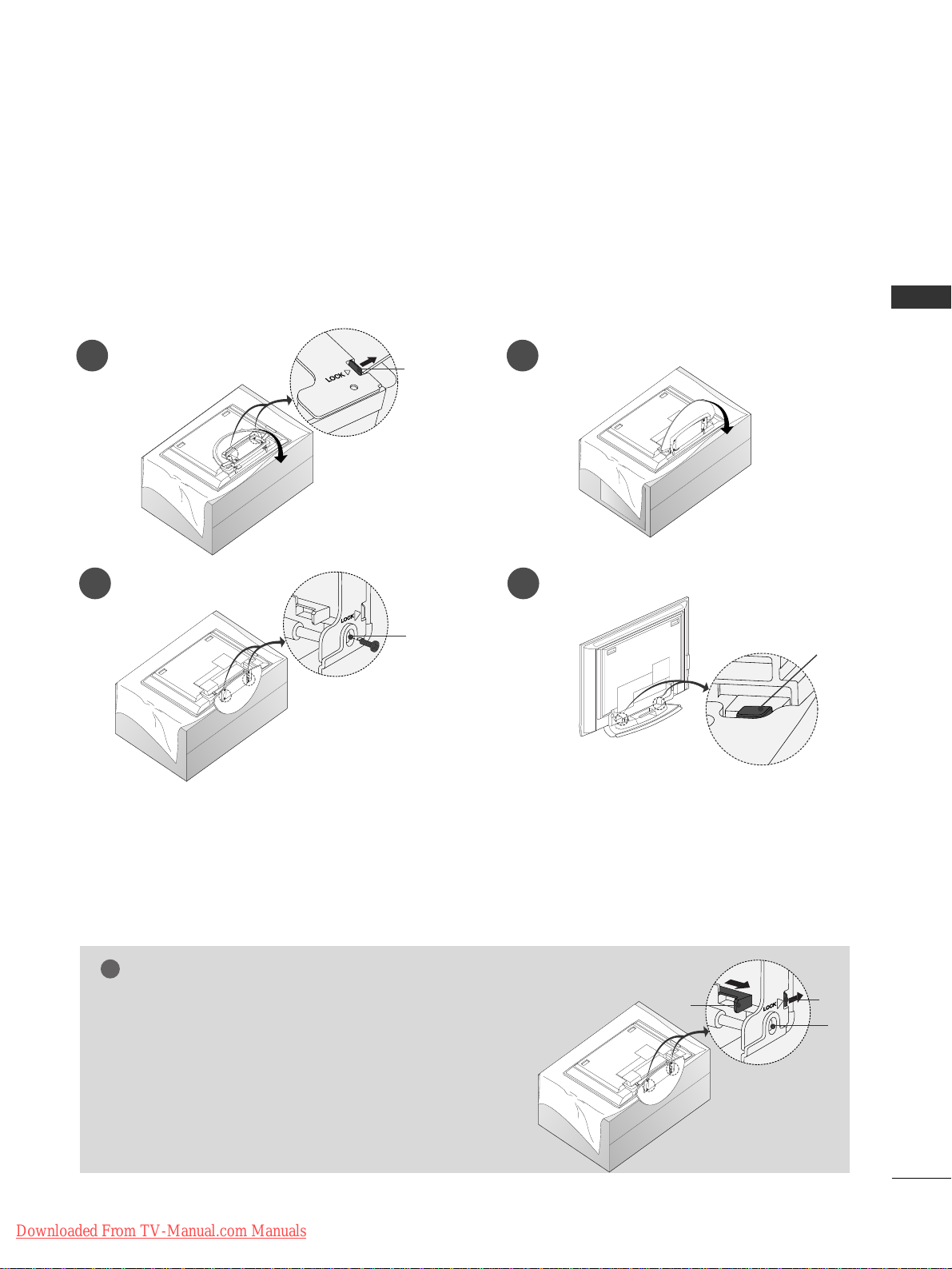
WWhheenn cclloossiinngg tthhee ssttaanndd ffoorr ssttoorraaggee
First remove the screws in the holes (B) on the bottom
of the stand. And then pull two Hooks (D) of the stand bottom
and fold the stand into the back of the set.
After folding, push two Locks (A) of the stand bottom outward.
NOTE
!
■
Place the set with the screen facing down on a cushion or soft cloth as shown in Figures 1.
Before unfolding the stand, please make sure two locks (A) on the bottom of the stand push outward.
■
Pull the stand out as shown above in Figures 2 ~ 3.
After unfolding the stand, please insert and tighten the screws in the holes (B) on the bottom of the stand.
■
When connecting cables to the set, Do not disengage the lock (C).
This may cause the set to fall, causing serious bodily injury and serious damage to the set.
A
D
A
C
B
B
1
3 4
2
Downloaded From TV-Manual.com Manuals
INSTALLATION
12
INSTALLATION
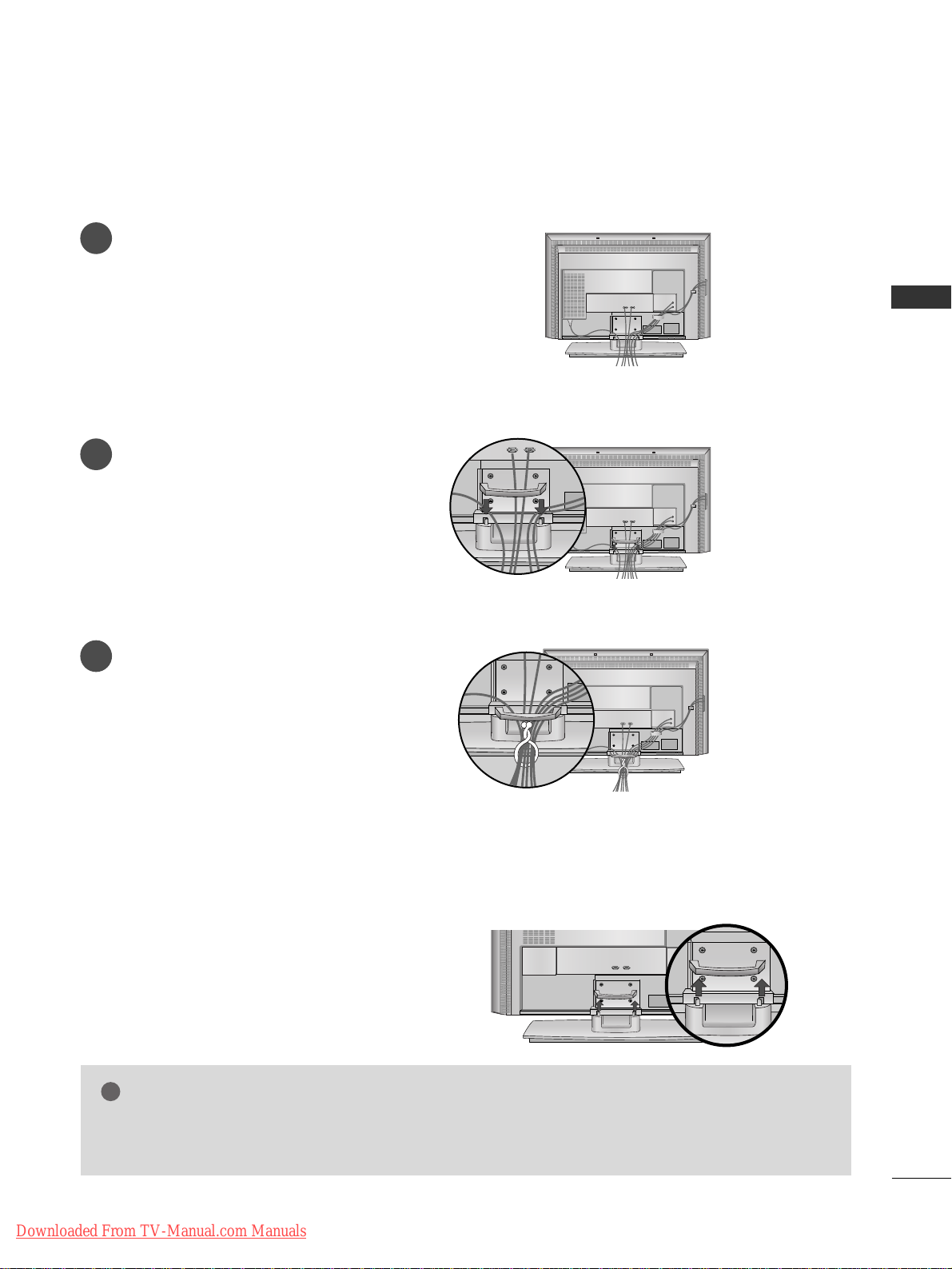
BASIC CONNECTION (42PC1RR
*,
50PC1RR *)
Arrange the cables as shown picture.
Hold the
CCAABBLLEE MMAANNAAGGEEMMEENNTT
with both
hands and push it as shown.
Connect the cables as necessary.
To connect an additional equipment, see the
EExx tteerrnnaall eeqquuiippmmeenntt CCoonnnn eeccttiioonnss
section.
Reinstall the
CCAABBLLEE MMAANNAAGG EEMMEENNTT
as
shown.
1
2
3
CABLE MANAGEMENT
■
These models have two cable arrangement methods according to the stand type.
Stand type 1
Stand type 2
Downloaded From TV-Manual.com Manuals
INSTALLATION
13
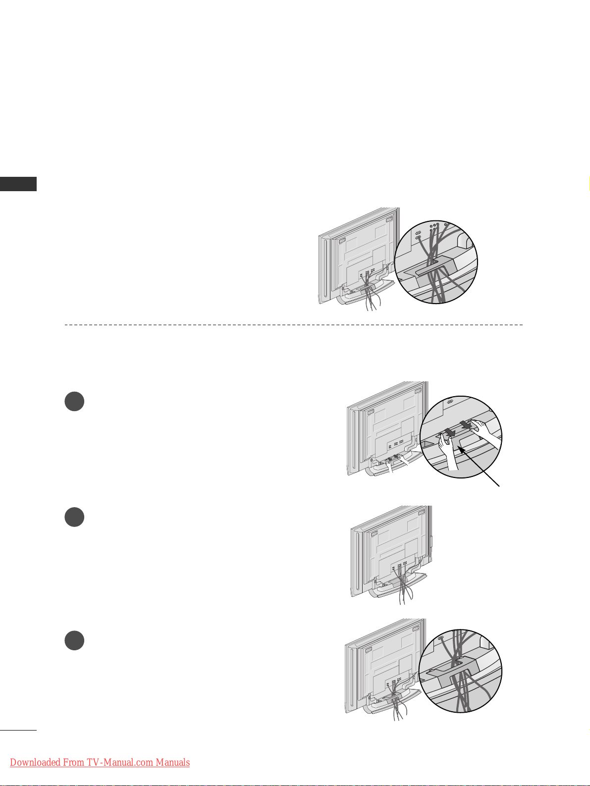
BASIC CONNECTION (37LC2RR
*
, 42LC2RR*)
Hold the
CCAABBLLEE MMAANNAAGG EEMMEENNTT
with both
hands and pull it upward.
NOTE
!
GG
Do not hold the
CCAABBLLEE MMAANNAAGG EEMMEENNTT
when moving the product.
If the product is dropped, you may be injured or the product may be broken.
HOW TO REMOVE THE CABLE MANAGEMENT
Connect the cables as necessary.
After connecting the cables neatly, arrange
the cables to the Cable Holder.
To connect an additional equipment, see the
CONNECTIONS & SETUP
section.
1
Install the
CCAABBLLEE MMAANNAAGG EEMMEENNTT
as shown.
2
Bundle the cables using the supplied
twister holder.
3
Downloaded From TV-Manual.com Manuals
INSTALLATION
14
INSTALLATION
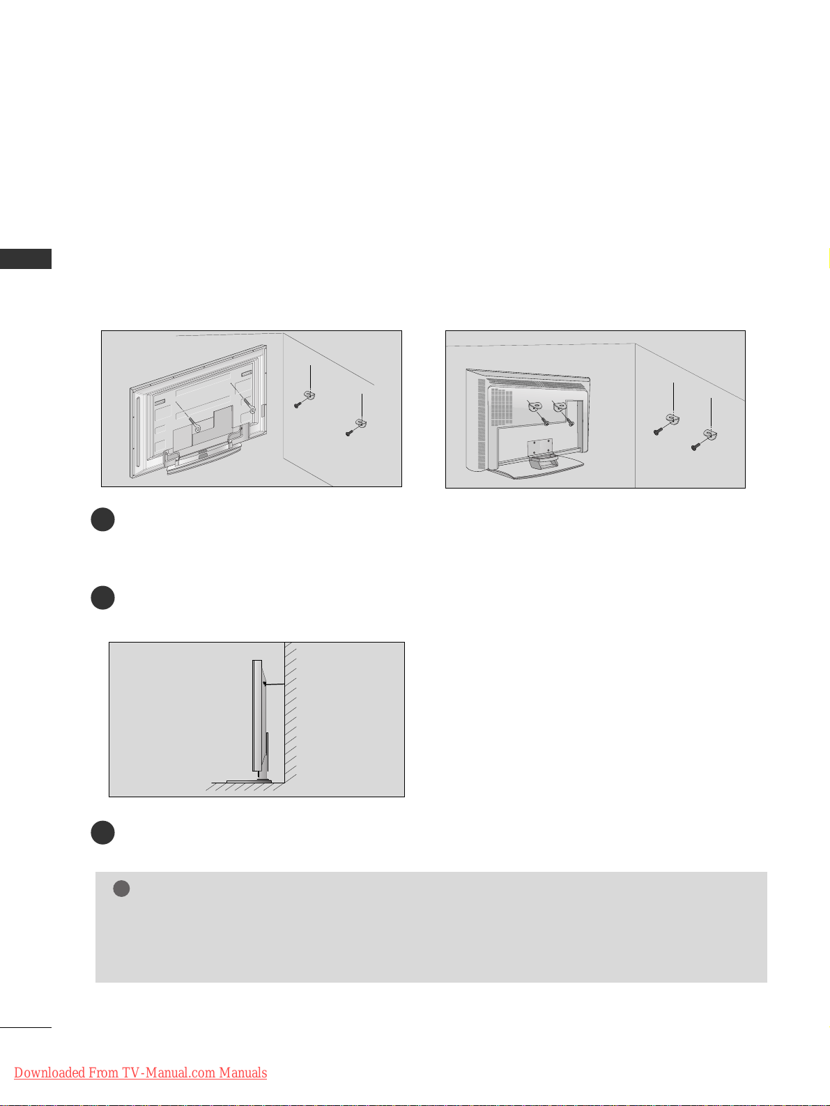
HOW TO JOIN THE SET ASSEMBLY TO THE WALL TO PROTECT THE SET TUMBLING
2
1
■
Set it up close to the wall so the set doesn’t fall over when it is pushed backwards.
■
The instructions shown below is a safer way to set up the set, which is to fix it on the wall so the set doesn’t fall over when it is pulled in the forward direction. It will prevent the set from falling for-ward and hurting people. It will also prevent the set from damage caused by fall. Please make sure that children don’t
climb on or hang from the set.
3
Use a sturdy rope (not provided as parts of the set, must purchase separately) to tie the set. It is safer to tie
the rope so it becomes horizontal between the wall and the set.
Use the eye-bolts or set brackets/bolts to fix the set to the wall as shown in the picture.
(If your set has the bolts in the eye-bolts position before inserting the eye-bolts, loosen the bolts.)
* Insert the eye-bolts or set brackets/bolts and tighten them securely in the upper holes.
Secure the wall brackets with the bolts (not provided as parts of the set, must purchase separately) on the
wall. Match the height of the bracket that is mounted on the wall.
NOTE
!
GG
When moving the set to another place undo the ropes first.
GG
Use a set holder or a cabinet that is big and strong enough for the size and weight of the set.
GG
To use the set safely make sure that the height of the bracket that is mounted on the wall is same as that
of the set.
2
3
1
1
3
2
or
Downloaded From TV-Manual.com Manuals
INSTALLATION
15
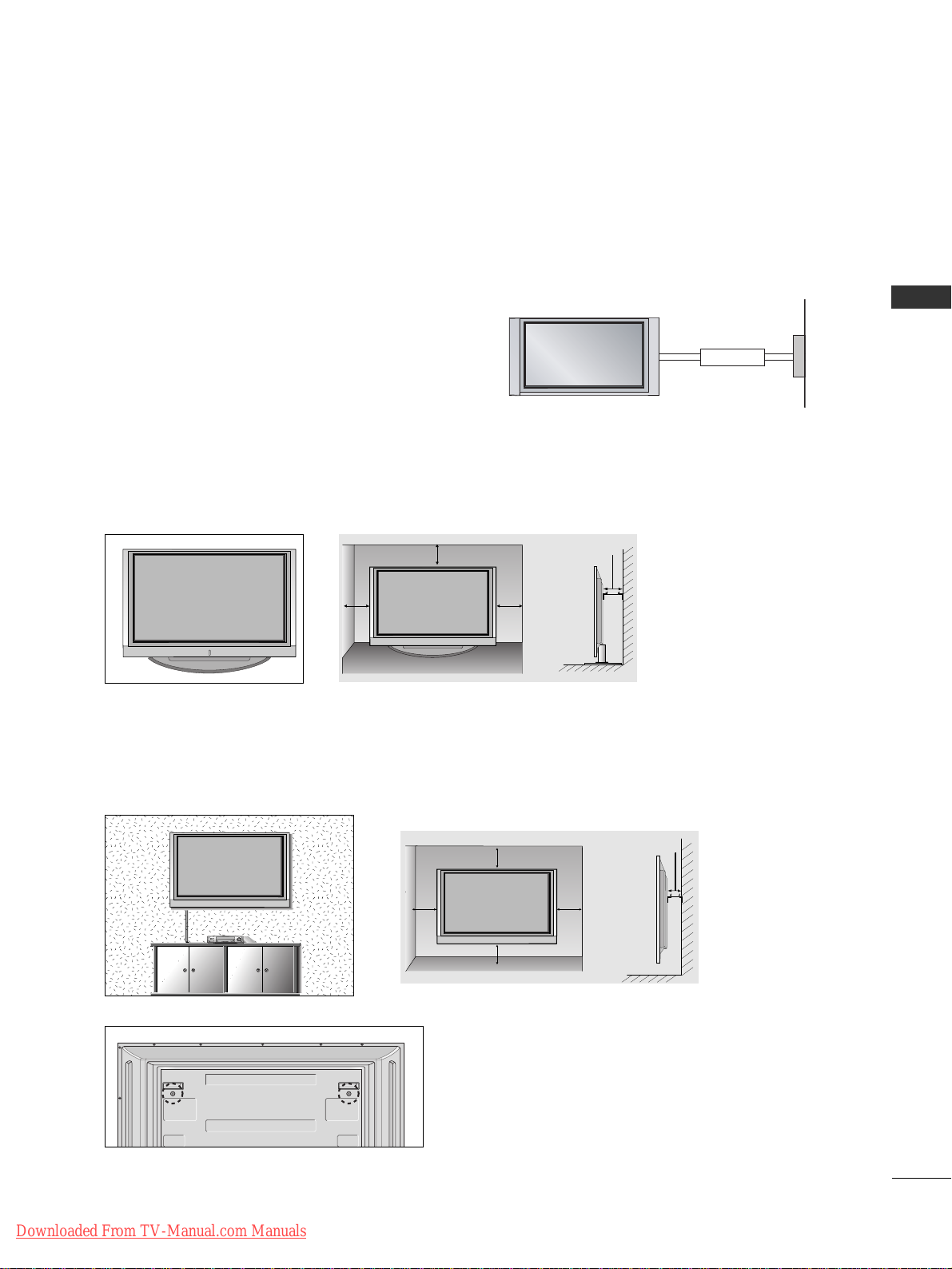
STAND INSTALLATION
Desktop Pedestal Installation
For proper ventilation, allow a clearance of 4" on each side and from the wall.
Wall Mount: Horizontal installation
For proper ventilation, allow a clearance of 4" on each side and from the wall. Detailed installation instructions are available from your dealer, see the optional Tilt Wall Mounting Bracket Installation and Setup Guide.
GGRROOUUNNDDIINNGG
Ensure that you connect the earth ground wire to prevent
possible electric shock. If grounding methods are not possible,
have a qualified electrician install a separate circuit breaker. Do
not try to ground the unit by connecting it to telephone
wires, lightening rods, or gas pipes.
Power
Supply
Short-circuit
Breaker
■
The set can be installed in various ways such as on a wall, or on a desktop etc.
■
The set is designed to be mounted horizontally.
<<OOnnllyy 4422PPCC11RRRR**>>
Remove two screws of the backside of the set before
installing the wall mounting bracket.
4 inches
4 inches4 inches
4 inches
Downloaded From TV-Manual.com Manuals
4 inches
4 inches
4 inches
4 inches
4 inches
CONNECTIONS & SETUP
16
CONNECTIONS & SETUP
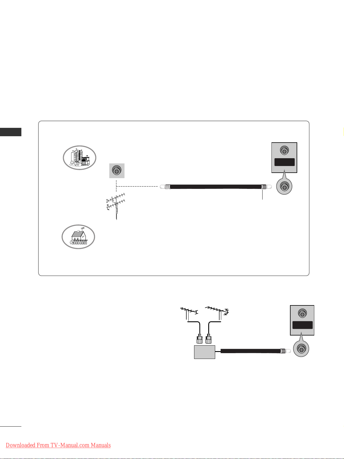
ANTENNA CONNECTION
■
To prevent the equipment damage, never plug in any power cords until you have finished connecting all equipment.
■
This part of CONNECTION & SETUP mainly use pictures for the 42PC1RR
*,
50PC1RR*.
■
For optimum picture quality, adjust antenna direction.
■
An antenna cable and converter are not supplied.
Multi-family Dwellings/Apartments
(Connect to wall antenna socket)
Single-family Dwellings /Houses
(Connect to wall jack for outdoor antenna)
Outdoor Antenna
Wall Antenna Socket
VHF Antenna
UHF Antenna
RF Coaxial Wire (75 ohm)
Turn clockwise to tighten.
ANTENNA
IN
■
In poor signal areas, to get better picture quality,
install a signal amplifier to the antenna as shown
to the right.
■
If signal needs to be split for two TVs, use an
antenna signal splitter for connection.
SSiiggnnaall
AAmmpplliiffiieerr
UHF
VHF
ANTENNA
IN
Downloaded From TV-Manual.com Manuals
CONNECTIONS & SETUP
17
VCR SETUP
■
To avoid picture noise (interference), leave an adequate distance between the VCR and TV.
■
Typically a frozen still picture from a VCR. If the 4:3 picture format is used; the fixed images on the sides of
the screen may remain visible on the screen.
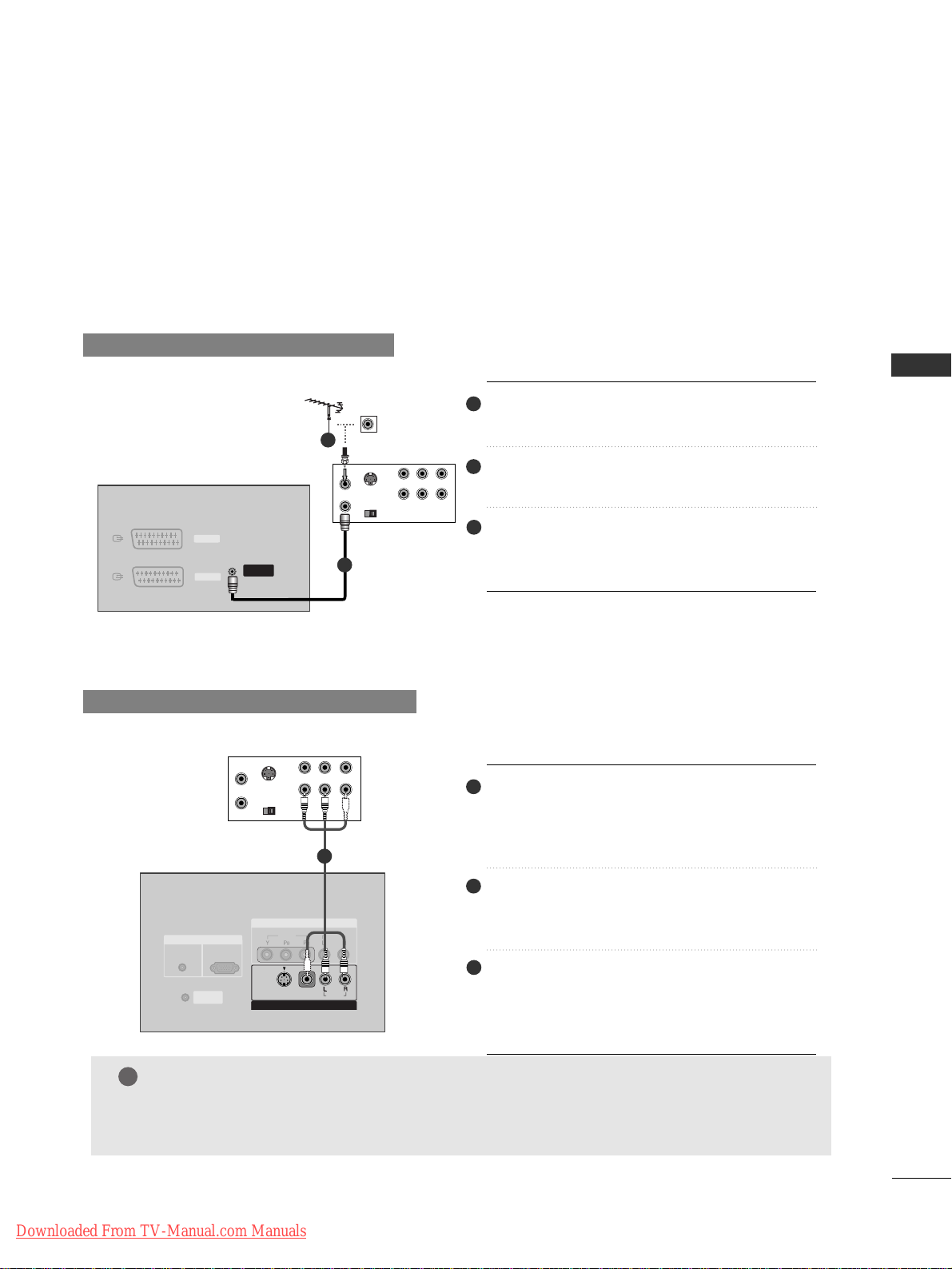
When connecting with an antenna
S-VIDEO
OUT
IN
(R) AUDIO (L) VIDEO
34
OUTPUT
SWITCH
ANT OUT
ANT IN
AV 1
AV 2
ANTENNA
IN
Connect the
AANNTT OOUUTT
of the VCR to the
AANNTTEENNNNAA IINN
socket on the set.
Connect the antenna cable to the
AANNTT II NN
antenna socket of the VCR.
Press the
PPLLAA YY
button on the VCR and match
the appropriate programme between the TV
and VCR for viewing.
VVCC RR
When connecting with a RCA cable
S-VIDEO
OUT
IN
(R) AUDIO (L) VIDEO
34
OUTPUT
SWITCH
ANT OUT
ANT IN
ANTENNA
IN
RGB IN
COMPONENT IN
VIDEO
AUDIO
MONO
( )
AUDIO
VIDEOVIDEO
S-VIDEO
AV IN 3V IN 3
RGB
(PC/DTV)
AUDIO
(RGB/DVI)
CONTROL IN
REMOTE
AV 1
AV 2
( )
AUDIO
VIDEO
S-VIDEO
AV IN 3
VVCC RR
Connect the
AAUUDD IIOO/VVIIDD EEOO
jacks between
TV and VCR. Match the jack colors (Video =
yellow, Audio Left = white, and Audio Right =
red)
Insert a video tape into the VCR and press
PLAY on the VCR. (Refer to the VCR owner’s
manual.)
Select
AAVV33
input source using the
IINNPPUUTT
button on the remote control.
- If connected to
AAVV IINN44
, select
AAVV44
input
source.
NOTE
!
GG
If you have a mono VCR, connect the audio cable from the VCR to the
AAUUDDII OO LL//MMOONNOO
jack
of the set.
2
1
3
1
2
3
1
2
1
Downloaded From TV-Manual.com Manuals
CONNECTIONS & SETUP
18
CONNECTIONS & SETUP
VCR SETUP
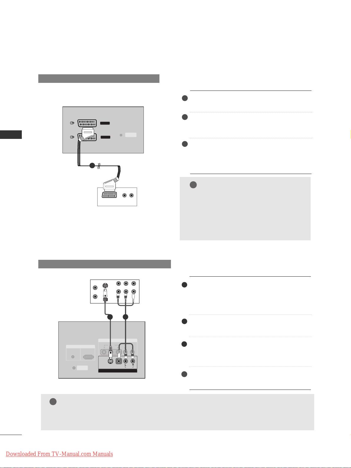
When connecting with an S-Video cable
S-VIDEO
OUT
IN
(R) AUDIO (L) VIDEO
34
OUTPUT
SWITCH
ANT OUT
ANT IN
AV IN 4
L/MONO
R
AUDIO
VIDEO
RGB IN
COMPONENT IN
VIDEO
AUDIO
MONO
( )
AUDIO
VIDEO
S-VIDEO
AV IN 3V IN 3
RGB
(PC/DTV)
AUDIO
(RGB/DVI)
CONTROL IN
REMOTE
VVCC RR
4
Connect the S-VIDEO output of the VCR to
the
SS --VVIIDDEEOO
input on the set. The picture
quality is improved; compared to normal composite (RCA cable) input.
Connect the audio outputs of the VCR to the
AAUUDD IIOO
input jacks on the set.
Insert a video tape into the VCR and press
PLAY on the VCR. (Refer to the VCR owner’s
manual.)
Select
AAVV 33
input source with using the
IINNPPUUTT
button on the remote control.
When connecting with a Euro Scart
GG
If the S-VIDEO(Y/C) signal is received
through the Euro scart socket 2 (AV2),
you must change to the S-Video2 mode.
GG
If you want to use the EURO scart cable,
you have to use the signal shielded Euro
scart cable.
ANTENNA
IN
AV IN 4
L/MONO
R
AUDIO
VIDEO
(R) AUDIO (L)
AUDIO/
VIDEO
AV 1
AV 2
( )
AUDIO
VIDEO
S-VIDEO
AV IN 3
VVCC RR
TTVV BBaacckk
1
2
3
Connect the Euro scart socket of the VCR to
the
AAVV11
Euro scart socket on the set.
Insert a video tape into the VCR and press
PLAY on the VCR. (Refer to the VCR owner’s
manual.)
Select
AAVV11
input source with using the
IINNPPUUTT
button on the remote control.
- If connected to
AAVV22
Euro scart socket,
select
AAVV22
input source.
NOTE
!
GG
If both S-Video and VIDEO sockets have been connected to the S-VHS VCR simultaneousiy.
only the S-Video can be received.
NOTE
!
1
1
2
3
1
2
Downloaded From TV-Manual.com Manuals
CONNECTIONS & SETUP
19
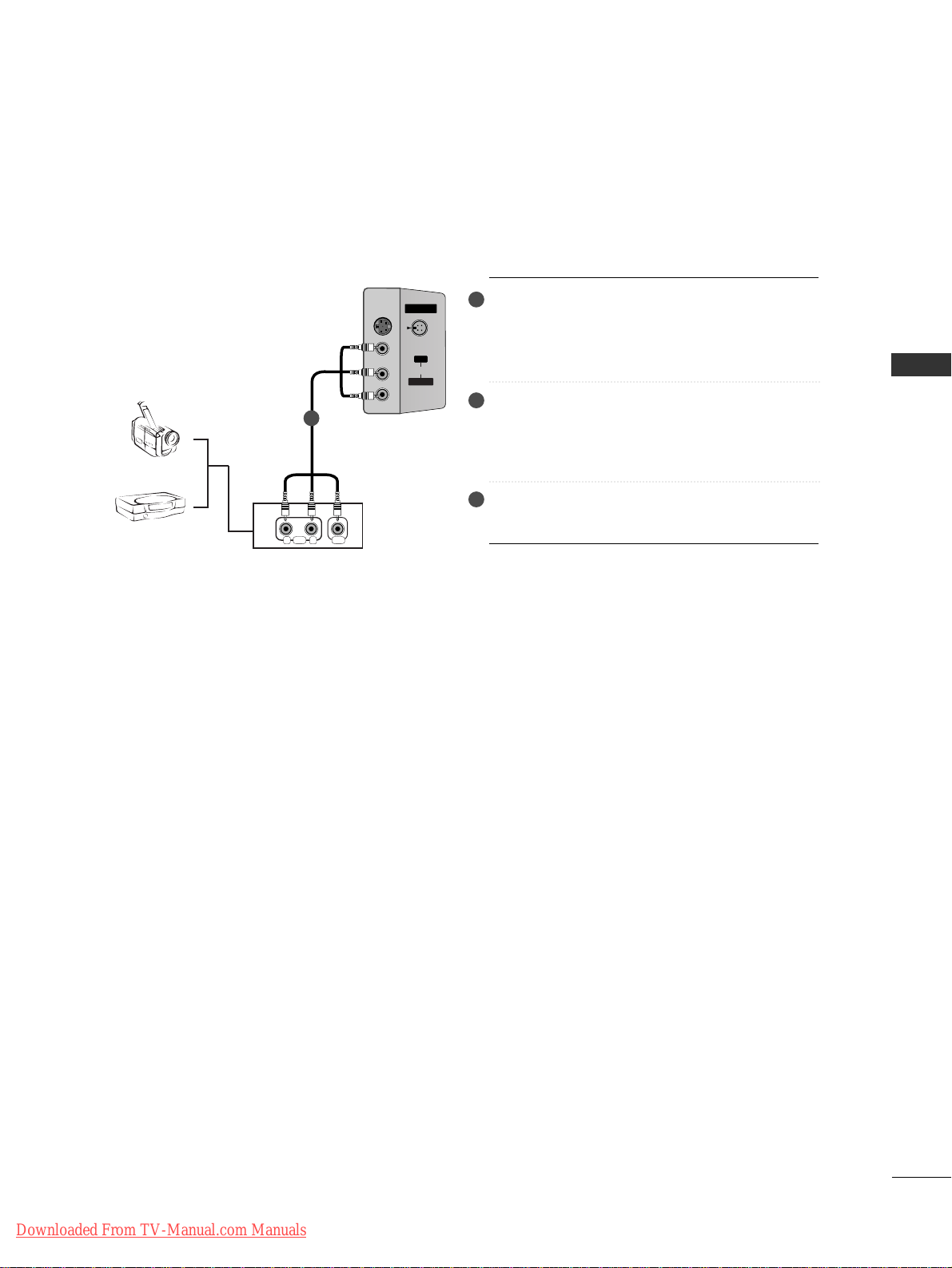
EXTERNAL EQUIPMENT CONNECTIONS
RL
AUDIO VIDEO
AV IN 4V IN 4
L/MONO
R
AUDIOAUDIO
VIDEOVIDEO
S-VIDEO
Camcorder
Video Game Set
1
Connect the
AAUUDD IIOO/VVIIDD EEOO
jacks between
TV and external equipment. Match the jack
colors (Video = yellow, Audio Left = white, and
Audio Right = red).
Select
AAVV 44
input source with using the
IINNPPUUTT
button on the remote control.
- If connected to
AAVV IINN 33
input, select
AAVV33
input source.
Operate the corresponding external equipment.
Refer to external equipment operating guide.
1
2
3
Downloaded From TV-Manual.com Manuals
CONNECTIONS & SETUP
20
CONNECTIONS & SETUP
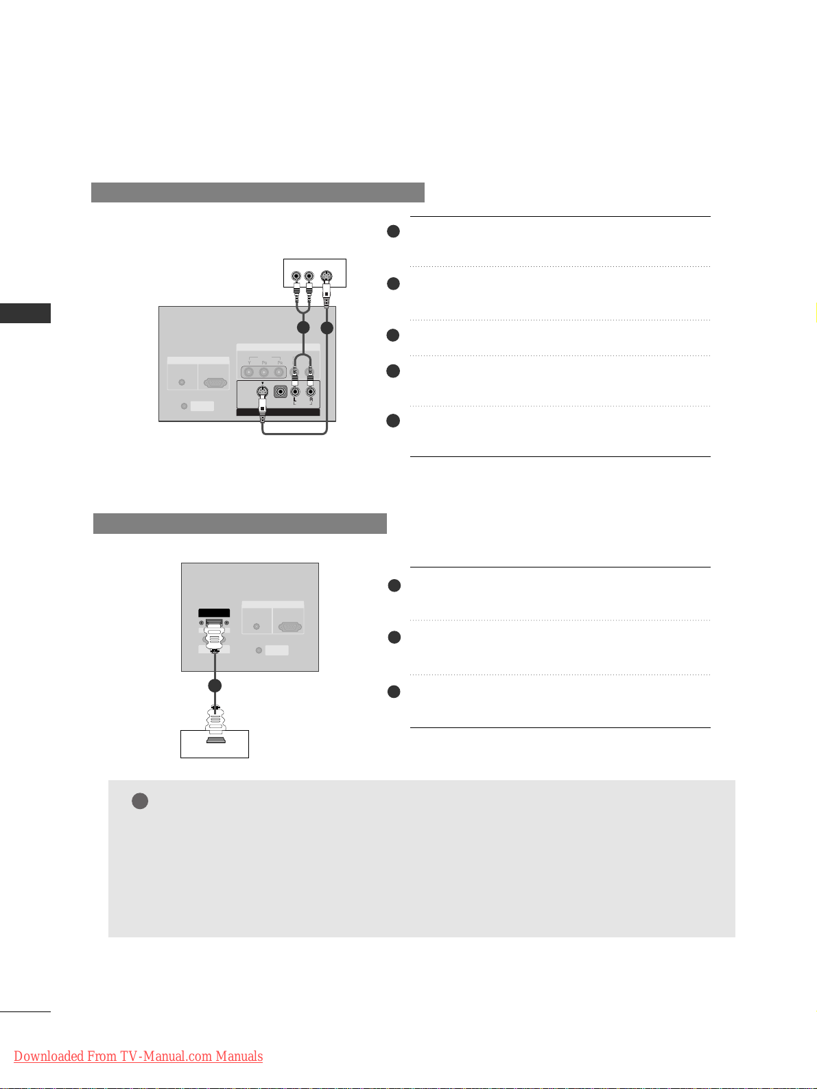
DVD SETUP
When connecting with a S-Video cable
AV IN 4
L/MONO
R
AUDIO
VIDEO
S-VIDEO
(R) AUDIO (L)
RGB IN
COMPONENT IN
VIDEO
AUDIO
MONO
( )
AUDIO
VIDEO
S-VIDEO
AV IN 3V IN 3
RGB
(PC/DTV)
AUDIO
(RGB/DVI)
CONTROL IN
REMOTE
COMPONENT IN
VIDEO
AUDIO
DDVVDD
When connecting with a HDMI cable
AV IN 4
L/MONO
R
AUDIO
VIDEO
HDMI OUTPUT
( )
AUDIO
VIDEO
S-VIDEO
AV IN 3
HDMI/
DVI IN
RS-232C IN
(CONTROL
& SERVICE)
RGB IN
RGB
(PC/DTV)
AUDIO
(RGB/DVI)
CONTROL IN
REMOTE
COMPONENT IN
VIDEO
AUDIO
RGB IN
RGB
(PC/DTV)
DDVVDD
11
Connect the S-VIDEO output of the DVD to the
SS --VVIIDDEEOO
input on the set.
Connect the audio outputs of the DVD to the
AAUUDD IIOO
input jacks on the set.
Turn on the DVD player, insert a DVD.
Select
AAVV33
input source with using the
IINNPPUUTT
button on the remote control.
Refer to the DVD player's manual for operating
instructions.
44
55
1
2
3
1
2
Connect the HDMI output of the DVD to the
HHDDMMII//DDVV II IINN
jack on the set.
Select
HHDDMMII//DDVVII
input source with using the
IINNPPUUTT
button on the remote control.
Refer to the DVD player's manual for operating
instructions.
1
NOTE
!
GG
Set can receive the video and audio signal simultaneously with using a HDMI cable.
GG
If the DVD supports Auto HDMI function, the DVD output resolution will be automatically set
to 1280x720p.
GG
If the DVD does not support Auto HDMI, you need to set the output resolution appropriately.
To get the best picture quality, adjust the output resolution of the DVD to 1280x720p.
2
3
Downloaded From TV-Manual.com Manuals
CONNECTIONS & SETUP
21
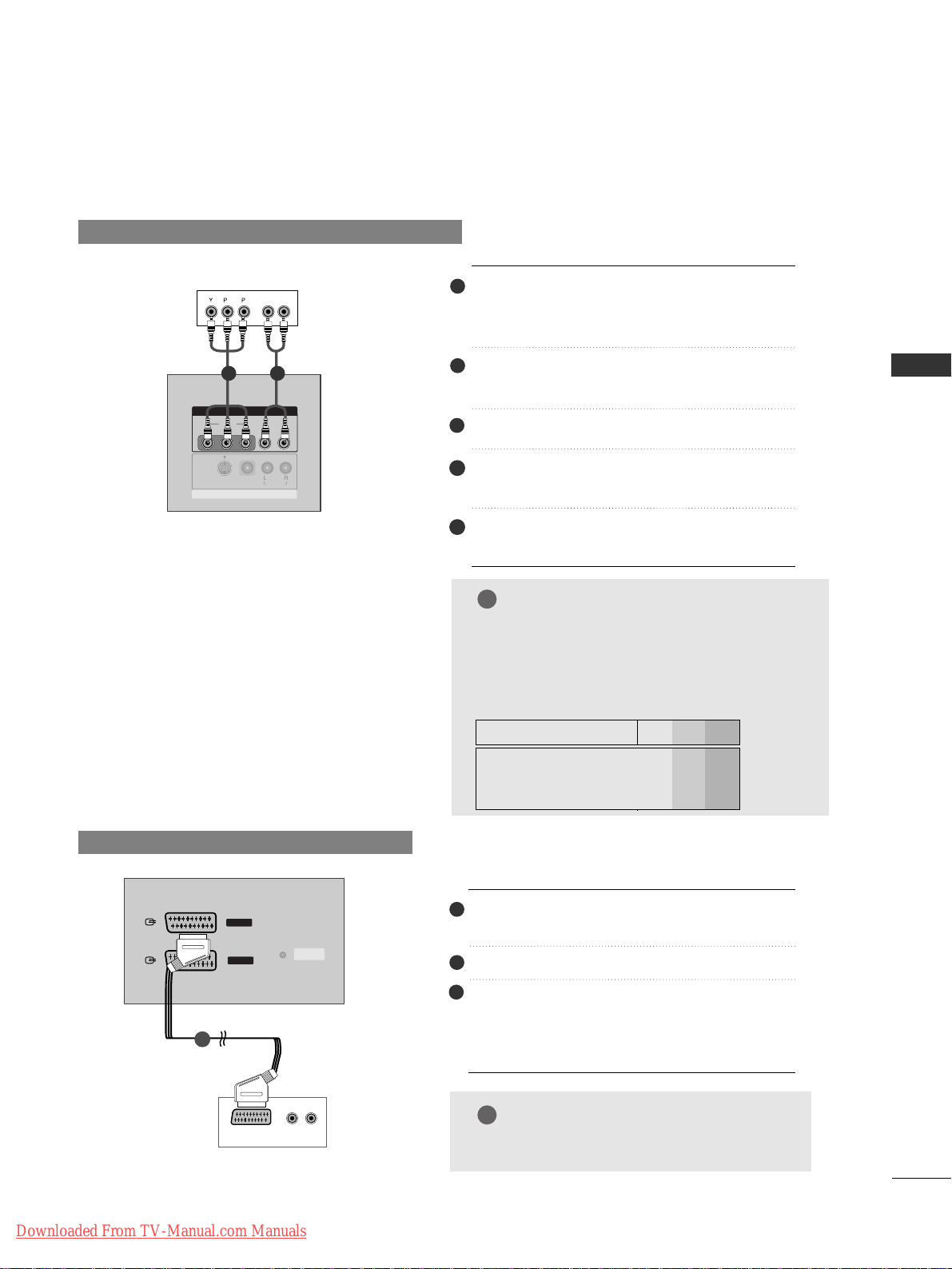
DVD SETUP
When connecting with a component cable
Connect the video outputs (Y, PB, PR) of the
DVD to the
CCOO MMPPOONNEENNTT II NN VV IIDDEEOO
jacks
on the set.
Connect the audio outputs of the DVD to the
CCOO MMPPOONNEENNTT IINN AA UUDDIIOO
jacks on the set.
Turn on the DVD player, insert a DVD.
Select
CCoommpp oonneenntt
input source with using
the
IINNPPUUTT
button on the remote control.
Refer to the DVD player's manual for operating
instructions.
B
R
(R) AUDIO (L)
MONO
( )
AUDIO
VIDEO
S-VIDEO
AV IN 3
COMPONENT IN
VIDEO
AUDIO
DDVVDD
When connecting with a Euro Scart
ANTENNA
IN
AV IN 4
L/MONO
R
AUDIO
VIDEO
(R) AUDIO (L)
AUDIO/
VIDEO
AV 1
AV 2
( )
AUDIO
VIDEO
S-VIDEO
AV IN 3
DVD
1
Connect the Euro scart socket of the DVD to
the
AAVV11
Euro scart socket on the set.
Turn on the DVD player, insert a DVD.
Select
AAVV 11
input source with using the
IINNPPUUTT
button on the remote control.
- If connected to
AAVV22
Euro scart socket,
select
AAVV22
input source.
44
55
1
2
3
1 2
1
2
3
NOTE
!
GG
Please use the shield scart cable.
NOTE
!
GG
CCoommppoonneenntt II nnppuutt ppoorr ttss
To get better picture quality, connect a DVD
player to the component input ports as
shown below.
Y PB
PR
Component ports on the SET
Y
Y
Y
Y
Pb
B-Y
Cb
PB
Pr
R-Y
Cr
PR
Video output ports
on DVD player
Downloaded From TV-Manual.com Manuals
CONNECTIONS & SETUP
22
CONNECTIONS & SETUP
■
This set can receive Digital Over-the-air/Cable signals without an external digital set-top box. However, if
you do receive Digital signals from a digital set-top box or other digital external device, refer to the figure
as shown below.
STB(SET-TOP BOX) SETUP
When connecting with a D-sub 15 pin cable
Connect the RGB output of the digital set-top
box to the
RRGGBB IINN ((PPCC//DDTTVV))
jack on the set.
Connect the audio outputs of the set-top box
to the
AAUUDDIIOO ((RRGGBB//DDVVII))
jack on the set.
Turn on the digital set-top box. (Refer to the
owner’s manual for the digital set-top box.)
Select
RRGG BB
input source with using the
IINNPPUUTT
button on the remote control.
(R) AUDIO (L)
RGB-DTV OUTPUT
CONTROL IN
REMOTE
RGB IN
RGB
(PC/DTV)
AUDIO
(RGB/DVI)
DDiiggiitt aall
SSeett--tt oopp
BB ooxx
When connecting with a HDMI cable
Connect the HDMI output of the digital settop box to the
HHDDMMII//DDVV II IINN
jack on the set.
Select
HHDDMMII//DD VVII
input source with using the
IINNPPUUTT
button on the remote control.
Turn on the digital set-top box. (Refer to the
owner’s manual for the digital set-top box.)
DDiiggiittaall SSeett--tt oopp BBooxx
GG
Set can receive the video and audio signal simultaneously with using a HDMI cable.
GG
If the digital set-top box supports Auto HDMI function, output resolution of the digital set-top
box will be automatically set to 1280x720p.
GG
If the digital set-top box does not support Auto HDMI, you need to set the output resolution
appropriately. To get the best picture quality, adjust the output resolution of the digital set-top
box to 1280x720p.
AV IN 4
L/MONO
R
AUDIO
VIDEO
HDMI OUTPUT
( )
AUDIO
VIDEO
S-VIDEO
AV IN 3
HDMI/
DVI IN
RS-232C IN
(CONTROL
& SERVICE)
RGB IN
RGB
(PC/DTV)
AUDIO
(RGB/DVI)
CONTROL IN
REMOTE
COMPONENT IN
VIDEO
AUDIO
RGB IN
RGB
(PC/DTV)
NOTE
!
44
1
2
3
1
2
1
2
3
1
Downloaded From TV-Manual.com Manuals
CONNECTIONS & SETUP
23
STB(SET-TOP BOX) SETUP
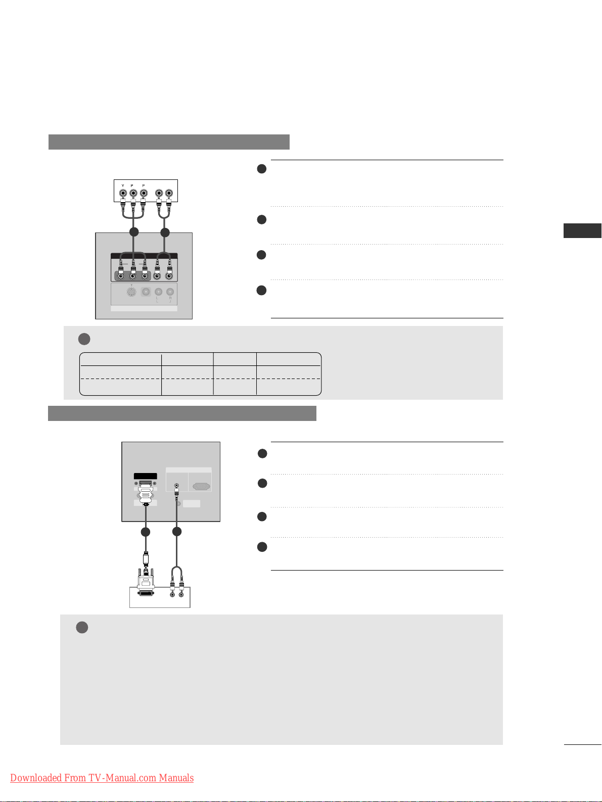
When connecting with a component cable
Connect the video outputs (Y, P
B, PR) of the digital
set-top box to the
CCOO MMPPOONNEENNTT IINN VVIIDDEE OO
jacks
on the set.
Connect the audio output of the digital set-top box
to the
CCOO MMPPOONNEENNTT IINN AAUUDDIIOO
jacks on the set.
Turn on the digital set-top box. (Refer to the owner’s
manual for the digital set-top box.)
Select
CCoommpp oonneenntt
input source with using the
IINNPPUUTT
button on the remote control.
B
R
(R) AUDIO (L)
MONO
( )
AUDIO
VIDEO
S-VIDEO
AV IN 3
COMPONENTCOMPONENT IN
VIDEO
AUDIO
DDiiggiittaall SSeett--tt oopp BBooxx
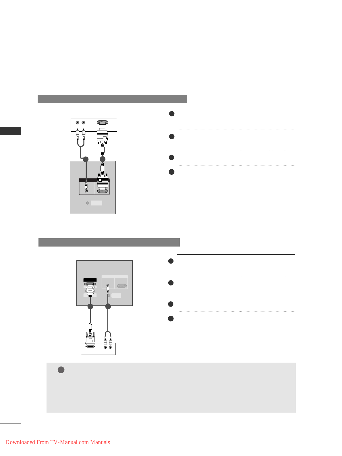
When connecting with a HDMI to DVI cable
GG
If the digital set-top box has a DVI output and no HDMI output, a separated audio connection
is necessary.
GG
If the digital set-top box supports Auto DVI function, the output resolution of the digital settop box will be automatically set to 1280x720p.
GG
If the digital set-top box does not support Auto DVI, you need to set the output resolution
appropriately. To get the best picture quality, adjust the output resolution of the digital settop box to 1280x720p.
(R) AUDIO (L)
DVI OUTPUT
COMPONENT IN
VIDEO
AUDIO
RGB IN
RGB
(PC/DTV)
HDMI/
DVI IN
RS-232C IN
(CONTROL
& SERVICE)
RGB IN
RGB
(PC/DTV)
AUDIO
(RGB/DVI)
CONTROL IN
REMOTE
DDiiggiittaall SSeett--ttoopp
BB ooxx
Connect the DVI output of the digital set-top box to
the
HHDDMMII//DDVV II IINN
jack on the set.
Connect the audio outputs of the set-top box to the
AAUUDDII OO ((RRGGBB//DDVVII))
jack on the set.
Turn on the digital set-top box. (Refer to the owner’s
manual for the digital set-top box.)
Select
HHDD MM II//DD VVII
input source with using the
IINNPPUUTT
button on the remote control.
NOTE
!
44
1
2
3
NOTE
!
1
1
2
2
44
1
2
3
Signal
480i/576i
480p/576p/720p/1080i
Component
Yes
Yes
RGB-DTV
No
Yes
HDMI-DTV
No
Yes
Downloaded From TV-Manual.com Manuals
CONNECTIONS & SETUP
24
CONNECTIONS & SETUP
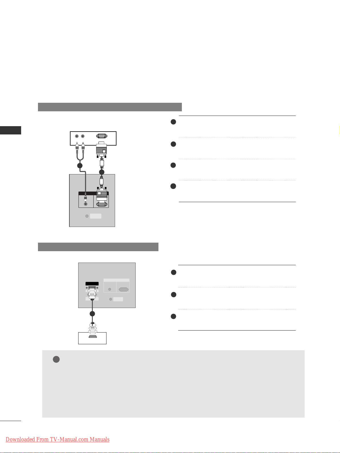
PC SETUP
When connecting with a D-sub 15 pin cable
Connect the RGB output of the PC to the
RRGGBB IINN ((PPCC// DDTTVV ))
jack on the set.
Connect the audio outputs of the PC to the
AAUUDDII OO ((RRGGBB//DDVVII))
jack on the set.
Turn on the PC and the set.
Select
RRGG BB
input source with using the
IINNPPUUTT
button on the remote control.
When connecting with a HDMI to DVI cable
Connect the DVI output of the PC to the
HHDDMMII//DDVV II IINN
jack on the set.
Connect the audio outputs of the PC to the
AAUUDDII OO ((RRGGBB//DDVVII))
jack on the set.
Turn on the PC and the set.
Select
HHDDMMII//DDVVII
input source with using the
IINNPPUUTT
button on the remote control.
GG
If the PC has a DVI output and no HDMI output, a separated audio connection is necessary.
GG
If the PC does not support Auto DVI, you need to set the output resolution appropriately. To
get the best picture quality, adjust the output resolution of PC graphics card's output resolution to 1024x768, 60Hz.
(R) AUDIO (L)
RGB-DTV OUTPUT
CONTROL IN
REMOTE
RGB IN
RGB
(PC/DTV)
AUDIO
(RGB/DVI)
PC
1
2
(R) AUDIO (L)
DVI OUTPUT
COMPONENT IN
VIDEO
AUDIO
RGB IN
RGB
(PC/DTV)
HDMI/
DVI IN
RS-232C IN
(CONTROL
& SERVICE)
RGB IN
RGB
(PC/DTV)
AUDIO
(RGB/DVI)
CONTROL IN
REMOTE
PC
1
2
■
This set provides Plug and Play capability, meaning that the PC adjusts automatically to the set's settings.
44
1
2
3
44
1
2
3
NOTE
!
Downloaded From TV-Manual.com Manuals

CONNECTIONS & SETUP
25
NOTE
!
G
To enjoy vivid picture and sound, connect a PC to
the set.
G
Avoid keeping a fixed image on the set’s screen for
a long period of time. The fixed image may
become permanently imprinted on the screen; use
a screen saver when possible.
G
Connect PC to the RGB (PC/DTV) or HDMI/DVI
port of the set; change the resolution output of
PC accordingly.
G
There might be noise according to some resolution, vertical pattern, contrast or brightness in PC
mode. Change the PC mode into another resolution or change the refresh rate into another rate
or adjust the brightness and contrast on the
menu until the picture is clean. If the refresh rate
of the PC graphic card can not be changed,
change the PC graphic card or consult it to the
manufacturer of the PC graphic card.
G
The synchronization input waveform for
Horizontal and Vertical frequencies are separate.
G
In 42PC1RR/50PC1RR models, we recommend
using 1024x768, 60Hz for the PC mode, they
provide the best picture quality.
G
In 37LC2RR/42LC2RR models, we recommend
using 1360x768, 60Hz for the PC mode, they
provide the best picture quality.
G
If the resolution of PC is over UXGA, there will be
no picture on the set.
G
Connect the signal cable from the monitor output
port of the PC to the RGB (PC/DTV) port of the
set or the signal cable from the HDMI output port
of the PC to the HDMI/DVI port on the set.
G
Connect the audio cable from the PC to the
Audio input on the set. (Audio cables are not
included with the set).
G
If using a sound card, adjust PC sound as required.
G
This set uses a VESA Plug and Play Solution. The
set provides EDID data to the PC system with a
DDC protocol. The PC adjusts automatically when
using this set.
G
DDC protocol is preset for RGB (Analog RGB),
HDMI (Digital RGB) mode.
G
If required, adjust the settings for Plug and Play
functionally.
G
If graphic card on the PC does not output analog
and digital RGB simultaneously, connect only one
of either RGB (PC/DTV) or HDMI/DVI to display
the PC on the set.
G
If graphic card on the PC does output analog and
digital RGB simultaneously, set the set to either
RGB or HDMI; (the other mode is set to Plug and
Play automatically by the set.)
G
DOS mode may not work depending on video
card if you use a HDMI to DVI cable.
G
When you use too long RGB-PC cable, there
might be a noise on the screen. We recommend
using under 5m of the cable. It provides the best
picture quality.
Downloaded From TV-Manual.com Manuals
CONNECTIONS & SETUP
26
CONNECTIONS & SETUP
31 . 4 6 8
37.861
31 . 4 6 9
37.927
31 . 4 6 9
35.000
37.861
37.500
43.269
31 . 5 0 0
37.799
39.375
31 . 5 0 0
37.799
39.375
35.156
37.879
48.077
46.875
53.674
49.725
48.363
56.476
60.023
68.677
47.70 0
47.70 0
54.348
63.995
47.776
70.09
85.08
70.08
85.03
59.94
66.66
72.80
75.00
85.00
60.00
70.00
75.00
60.00
70.00
75.00
56.25
60.31
72.18
75.00
85.06
74 . 55
60.00
70.06
75.02
85.00
60.00
60.00
60.05
70.01
59.87
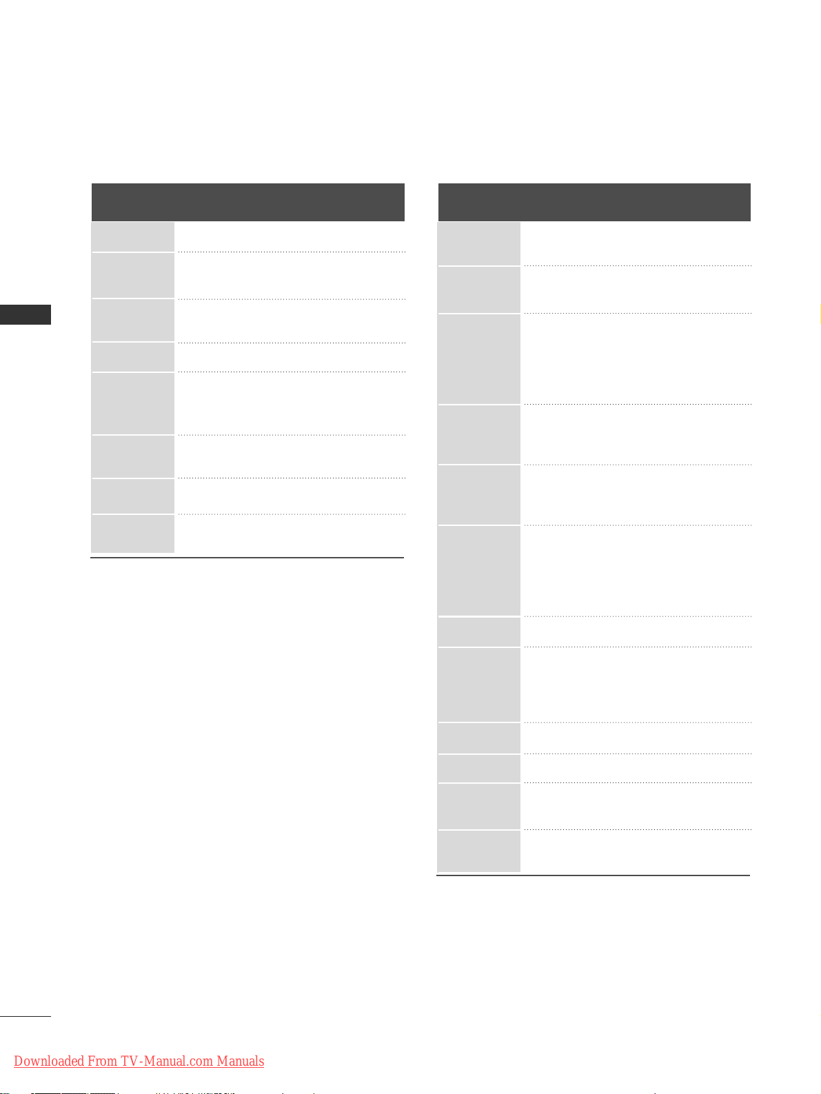
Resolution
Horizontal Vertical
Frequency(KHz) Frequency(Hz)
640x350
Supported Display Resolution (RGB / HDMI mode)
(42PC1RR
*,
50PC1RR *)
720x400
640x480
848x480
800x600
852x480
832x624
1024x768
1360x768
1366x768
1152x864
1280x768
Supported Display Resolution (RGB / HDMI mode)
(37LC2RR
*,
42LC2RR *)
31 . 4 6 8
31 . 4 6 9
37.684
37.879
46.875
49.725
48.363
56.47
60.123
47.776
47.720
47.720
70.8
59.94
75.00
60.31
75.00
74 . 55
60.00
70.00
75.029
59.870
59.799
59.799
Resolution
Horizontal Vertical
Frequency(KHz) Frequency(Hz)
720x400
640x480
800x600
832x624
1280x768
1024x768
1360x768
1366x768
Downloaded From TV-Manual.com Manuals
BASIC OPERATION
27
BASIC OPERATION
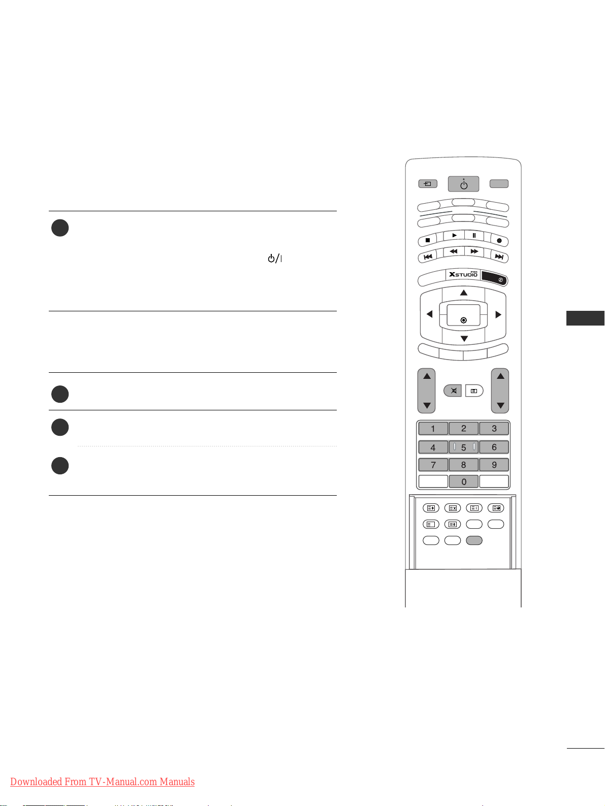
TURNING THE SET ON
If your set will be turned on, you will be able to use its features.
First, connect power cord correctly.
At this moment, the set switches to standby mode.
■
In standby mode to turn set on, press the ,
IINNPPUUTT
,
PPRR
DD
//
EE
button on the set or press the
PPOOWWEERR
,
IINNPPUUTT, MMUULLTTIIMMEEDDIIAA,PPRR
DD
//
EE
,
NNUUMMBBEERR
button
on the remote control and then the set will switch on.
MODE
INPUT
TV
DVD
VCR
AUDIO
P
IP
P
R
-
PIP PR +
S
W
A
P
PIP IN
PUT
STB
MENU
SIZE POSITION INDEX
SLEEP
FAV
I/II
PIP ARC
Q.VIEWLIST
OK
VOL PR
MULTIMEDIA
CABLE
HOLD
REVEAL
?
TIME
EXIT
MARK
LIV
E TV
TIME
SHIFT
TIME
SHIFT
MUTE
TEXT
POWER
Turning the set on
Press the
VVOOLL
DD
//
EE
button to adjust the volume.
If you want to switch the sound off, press the
MMUUTTEE
button.
You can cancel this function by pressing the
MM UU TTEE
,
VVOO LL
DD
//
EE
or
II// IIII
button.
Volume Adjustment
1
1
2
3
Downloaded From TV-Manual.com Manuals
BASIC OPERATION
28
BASIC OPERATION
Press the
EEXXIITT
button to return to normal TV viewing.
TURNING THE SET ON
MODE
INPUT
TV
DVD
VCR
AUDIO
P
IP
P
R
-
PIP PR +
S
W
A
P
PIP IN
PU
T
STB
MENU
SIZE POSITION INDEX
SLEEP
FAV
I/II
PIP ARC
Q.VIEWLIST
OK
VOL PR
MULTIMEDIA
CABLE
HOLD
REVEAL
?
TIME
EXIT
MARK
LIVE TV
TIME
SHIFT
TIME
SHIFT
POWER
MUTE
TEXT
Press the
PPRR
DD
//
EE
or NUMBER button to select a pro-
gramme number.
Programme selection
NOTE
!
GG
If you intend to be away on vacation, disconnect the power plug from wall power outlet.
1
Press the
MMEENNUU
button and then use
DD
//
EE
button to select
the SPECIAL menu.
Press the GGbutton and then use
DD
//
EE
button to select
LLaanngguuaa ggee
.
Press the
GG
button and then use
DD
//
EE
button to select
your desired language. From this point on, the on-screen
menus will be shown in the language of your choice.
On-Screen Menu Language Selection (option)
--
The menus can be shown on the screen in the selected language.
First select your language.
1
2
3
4
Downloaded From TV-Manual.com Manuals
 Loading...