

LG 32LV570G, 32LV570S, 32LV571S, 42LV570G, 42LV570S Service Manual
...
LED LCD TV
SERVICE MANUAL
CAUTION
BEFORE SERVICING THE CHASSIS,
READ THE SAFETY PRECAUTIONS IN THIS MANUAL.
CHASSIS : LD12E
MODEL: 32LV570G/570S/571S
MODEL: 32LV570G/570S-ZB 32LV571S-ZA
North/Latin America http://aic.lgservice.com
Europe/Africa http://eic.lgservice.com
Asia/Oceania http://biz.lgservice.com
Internal Use Only
Printed in KoreaP/NO : MFL67002336 (1103-REV00)

- 2 -
LGE Internal Use OnlyCopyright © 2011 LG Electronics. Inc. All rights reserved.
Only for training and service purposes
CONTENTS
CONTENTS .............................................................................................. 2
PRODUCT SAFETY ................................................................................. 3
SPECIFICATION ...................................................................................... 4
ADJUSTMENT INSTRUCTION ............................................................. 10
BLOCK DIAGRAM ................................................................................. 19
EXPLODED VIEW .................................................................................. 20
SCHEMATIC CIRCUIT DIAGRAM ..............................................................
- 3 -
LGE Internal Use OnlyCopyright © 2011 LG Electronics. Inc. All rights reserved.
Only for training and service purposes
SAFETY PRECAUTIONS
Many electrical and mechanical parts in this chassis have special safety-related characteristics. These parts are identified by in the
Schematic Diagram and Exploded View.
It is essential that these special safety parts should be replaced with the same components as recommended in this manual to prevent
Shock, Fire, or other Hazards.
Do not modify the original design without permission of manufacturer.
General Guidance
An isolation Transformer should always be used during the
servicing of a receiver whose chassis is not isolated from the AC
power line. Use a transformer of adequate power rating as this
protects the technician from accidents resulting in personal injury
from electrical shocks.
It will also protect the receiver and it's components from being
damaged by accidental shorts of the circuitry that may be
inadvertently introduced during the service operation.
If any fuse (or Fusible Resistor) in this TV receiver is blown,
replace it with the specified.
When replacing a high wattage resistor (Oxide Metal Film Resistor,
over 1 W), keep the resistor 10 mm away from PCB.
Keep wires away from high voltage or high temperature parts.
Before returning the receiver to the customer,
always perform an AC leakage current check on the exposed
metallic parts of the cabinet, such as antennas, terminals, etc., to
be sure the set is safe to operate without damage of electrical
shock.
Leakage Current Cold Check(Antenna Cold Check)
With the instrument AC plug removed from AC source, connect an
electrical jumper across the two AC plug prongs. Place the AC
switch in the on position, connect one lead of ohm-meter to the AC
plug prongs tied together and touch other ohm-meter lead in turn to
each exposed metallic parts such as antenna terminals, phone
jacks, etc.
If the exposed metallic part has a return path to the chassis, the
measured resistance should be between 1 MΩ and 5.2 MΩ.
When the exposed metal has no return path to the chassis the
reading must be infinite.
An other abnormality exists that must be corrected before the
receiver is returned to the customer.
Leakage Current Hot Check (See below Figure)
Plug the AC cord directly into the AC outlet.
Do not use a line Isolation Transformer during this check.
Connect 1.5 K / 10 watt resistor in parallel with a 0.15 uF capacitor
between a known good earth ground (Water Pipe, Conduit, etc.)
and the exposed metallic parts.
Measure the AC voltage across the resistor using AC voltmeter
with 1000 ohms/volt or more sensitivity.
Reverse plug the AC cord into the AC outlet and repeat AC voltage
measurements for each exposed metallic part. Any voltage
measured must not exceed 0.75 volt RMS which is corresponds to
0.5 mA.
In case any measurement is out of the limits specified, there is
possibility of shock hazard and the set must be checked and
repaired before it is returned to the customer.
Leakage Current Hot Check circuit
1.5 Kohm/10W
To Instrument’s
exposed
METALLIC PARTS
Good Earth Ground
such as WATER PIPE,
CONDUIT etc.
AC Volt-meter
When 25A is impressed between Earth and 2nd Ground
for 1 second, Resistance must be less than 0.1
*Base on Adjustment standard
IMPORTANT SAFETY NOTICE
0.15 uF
Ω

- 4 -
LGE Internal Use OnlyCopyright © 2011 LG Electronics. Inc. All rights reserved.
Only for training and service purposes
SPECIFICATION
NOTE : Specifications and others are subject to change without notice for improvement
.
1. Application range
This specification is applied to the LED LCD TV used LD12E
chassis.
2. Requirement for Test
Each part is tested as below without special appointment.
1) Temperature: 25 ºC ± 5 ºC(77 ºF ± 9 ºF), CST: 40 ºC ± 5 ºC
2) Relative Humidity: 65 % ± 10 %
3) Power Voltage
: Standard input voltage(AC 100-240 V~ 50/60 Hz)
* Standard Voltage of each products is marked by models.
4) Specification and performance of each parts are followed
each drawing and specification by part number in
accordance with BOM.
5) The receiver must be operated for about 5 minutes prior to
the adjustment.
3. Test method
1) Performance: LGE TV test method followed
2) Demanded other specification
- Safety : CE, IEC specification
- EMC :CE, IEC
4. Model General Specification
No. Item Specification Remarks
1 Market EU(PAL Market-36Countries) DTV & Analog (Total 36 countries)
DTV (MPEG2/4, DVB-T) : 31 countries
(England/Italy/Germany/France/Spain/Sweden/Finland/Netherlands/Belgium/Luxemburg/
Greece/Denmark/Czech/Austria/Hungary/Swiss/Croatia/Turkey/Norway/Slovenia/Poland/
Ukraine/Portugal/Ireland/Morocco/Latvia/Estonia/Lithuania/Rumania/Russia/Slovakia)
DTV (MPEG2/4, DVB-T2): 5 countries (England/Denmark/Sweden/Finland/Norway)
DTV (MPEG2/4, DVB-C): 10 countries
Sweden/Finland/Austria/Swiss/Germany/Netherlands/Hungary/Slovenia/Norway/Denmark
DTV (MPEG2/4,DVB-S): 31 countries
Albania/Austria/Belgium/Bosnia/Bulgaria/Croatia/Czech/Estonia/France/Germany/Greece/
Hungary/Ireland/Italy/Kazakhstan/Latvia/Lithuania/Luxembourg/Morocco/Netherlands/Poland/
Portugal/Romania/Russia/Serbia/Slovenia/Spain/Slovakia/Switzerland/Turkey/Ukraine
Analog Only - 5 countries (Bosnia/Serbia/Bulgaria/Albania/Kazakhstan)
Supported satellite : 22 satellites
HISPASAT 1C/1D, ATLANTIC BIRD 2, NILESAT 101/102, ATLANTIC BIRD 3, AMOS 2/3,
THOR 5/6, IRIUS 4, EUTELSAT-W3A, EUROBIRD 9A, EUTELSAT-W2A, HOTBIRD 6/8/9,
EUTELSAT-SESAT, ASTRA 1L/H/M/KR, ASTRA 3A/3B, BADR 4/6, ASTRA 2D, EUROBIRD
3, EUTELSAT-W7, HELLASSAT 2, EXPRESS AM1, TURKSAT 2A/3A, INTERSAT10
2 Broadcasting system 1) PAL-BG
2) PAL-DK
3) PAL-I/I’
4) SECAM L/L’, DK, BG, I
5) DVB-T
6) DVB-C
7) DVB-T2
8) DVB-S DVB-S :Satellite
- 5 -
LGE Internal Use OnlyCopyright © 2011 LG Electronics. Inc. All rights reserved.
Only for training and service purposes
No. Item Specification Remarks
3 Receiving system Analog : Upper Heterodyne
G DVB-T
Digital : COFDM , QAM - Guard Interval(Bitrate_Mbit/s)
1/4, 1/8, 1/16, 1/32
- Modulation : Code Rate
QPSK : 1/2, 2/3, 3/4, 5/6, 7/8
16-QAM : 1/2, 2/3, 3/4, 5/6, 7/8
64-QAM : 1/2, 2/3, 3/4, 5/6, 7/8
G DVB-T2
- Guard Interval(Bitrate_Mbit/s)
1/4,1/8,1/16,1/32,1/128,19/128,19/256,
- Modulation : Code Rate
QPSK : 1/2, 2/5, 2/3, 3/4, 5/6
16-QAM : 1/2, 2/5, 2/3, 3/4, 5/6
64-QAM : 1/2, 2/5, 2/3, 3/4, 5/6
256-QAM : 1/2, 2/5, 2/3, 3/4, 5/6
G DVB-C
- Symbolrate : 4.0Msymbols/s to 7.2Msymbols/s
- Modulation : 16QAM, 64-QAM, 128-QAM and 256-QAM
G DVB-S
- Symbolrate
DVB-S2 (8PSK/ QPSK) : 2 ~ 45 Msymbol/s
DVB-S (QPSK) : 2~ 45 Msymbol/s
-viterbi
DVB-S mode :1/2, 2/3, 3/4, 5/6, 7/8
DVB-S2 mode : 1/2, 23, 3/4, 3/5, 4/5, 5/6, 8/9, 9/10
4
Scart Gender Jack(1EA)
PAL, SECAM
Scart Jack is Full scart and support MNT/DTV-OUT, DTV Recording(not support DTV Auto AV)
5 Video Input RCA(2EA) PAL, SECAM, NTSC 4System : PAL, SECAM, NTSC, PAL60
Rear 1EA, AV gender jack 1EA
6 Head phone out Antenna, AV1, AV2, AV3,
Component, RGB, HDMI1, HDMI2,
HDMI3, HDMI4 USB
7 Component Input(1EA) Y/Cb/Cr, Y/Pb/Pr Component Gender 1EA
8 RGB Input RGB-PC Analog(D-SUB 15PIN)
9 HDMI Input (4EA) HDMI1-DTV/DVI PC(HDMI version 1.3)
HDMI2-DTV Support HDCP
HDMI3-DTV
HDMI4-DTV
10 Audio Input (4EA) RGB/DVI Audio, Component, AV1, 2 L/R Input
11 SDPIF out (1EA) SPDIF out
12 USB (2EA) EMF, DivX HD, JPEG, MP3, DivX HD
For Service (download) - USB current : max 500 mA
- USB voltage : 4.75 V - 5.25 V
13 Wireless jack (1EA) 24V power & control Voltage : 24 V, Power : max 8 W
- 6 -
LGE Internal Use OnlyCopyright © 2011 LG Electronics. Inc. All rights reserved.
Only for training and service purposes
5. Component Video Input (Y, CB/PB, CR/PR)
No.
Specification
Remark
Resolution H-freq(kHz) V-freq(Hz)
1. 720x480 15.73 60.00 SDTV,DVD 480i
2. 720x480 15.63 59.94 SDTV,DVD 480i
3. 720x480 31.47 59.94 480p
4. 720x480 31.50 60.00 480p
5. 720x576 15.625 50.00 SDTV,DVD 625 Line
6. 720x576 31.25 50.00 HDTV 576p
7. 1280x720 45.00 50.00 HDTV 720p
8. 1280x720 44.96 59.94 HDTV 720p
9. 1280x720 45.00 60.00 HDTV 720p
10. 1920x1080 31.25 50.00 HDTV 1080i
11. 1920x1080 33.75 60.00 HDTV 1080i
12. 1920x1080 33.72 59.94 HDTV 1080i
13. 1920x1080 56.250 50 HDTV 1080p
14. 1920x1080 67.5 60 HDTV 1080p
No.
Specification
Proposed Remarks
Resolution H-freq(kHz) V-freq(Hz) Pixel Clock(MHz)
1. 720*400 31.468 70.08 28.321 For only DOS mode
2. 640*480 31.469 59.94 25.17 VESA Input 848*480 60 Hz, 852*480 60 Hz
-> 640*480 60 Hz Display
3. 800*600 37.879 60.31 40.00 VESA
4. 1024*768 48.363 60.00 65.00 VESA(XGA)
5. 1360*768 47.72 59.8 84.75 WXGA
6. 1920*1080 66.587 59.93 138.625 WUXGA FHD model
6. RGB (PC)
- 7 -
LGE Internal Use OnlyCopyright © 2011 LG Electronics. Inc. All rights reserved.
Only for training and service purposes
7. HDMI Input
(1) DTV Mode
No. Resolution H-freq(kHz) V-freq.(Hz) Pixel clock(MHz) Proposed Remark
1. 720*400 31.468 70.08 28.321 HDCP
2. 640*480 31.469 59.94 25.17 VESA HDCP
3. 800*600 37.879 60.31 40.00 VESA HDCP
4. 1024*768 48.363 60.00 65.00 VESA(XGA) HDCP
5. 1360*768 47.72 59.8 84.75 WXGA HDCP
6. 1280*1024 63.595 60.0 108.875 SXGA HDCP/FHD model
7. 1920*1080 67.5 60.00 138.625 WUXGA HDCP/FHD model
(2) PC Mode
No. Resolution H-freq(kHz) V-freq.(Hz) Pixel clock(MHz) Proposed Remark
1. 720*480 31.469 /31.5 59.94 /60 27.00/27.03 SDTV 480P
2. 720*576 31.25 50 54 SDTV 576P
3. 1280*720 37.500 50 74.25 HDTV 720P
4. 1280*720 44.96 /45 59.94 /60 74.17/74.25 HDTV 720P
5. 1920*1080 33.72 /33.75 59.94 /60 74.17/74.25 HDTV 1080I
6. 1920*1080 28.125 50.00 74.25 HDTV 1080I
7. 1920*1080 26.97 /27 23.97 /24 74.17/74.25 HDTV 1080P
8. 1920*1080 33.716 /33.75 29.976 /30.00 74.25 HDTV 1080P
9. 1920*1080 56.250 50 148.5 HDTV 1080P
10. 1920*1080 67.43 /67.5 59.94 /60 148.35/148.50 HDTV 1080P
- 8 -
LGE Internal Use OnlyCopyright © 2011 LG Electronics. Inc. All rights reserved.
Only for training and service purposes
8. 3D Mode
(1) HDMI Input (1.4a)
No. Resolution H-freq(kHz) V-freq.(Hz) Pixel clock(MHz) Proposed 3D input proposed mode
1 1920*1080 53.95 / 54 23.98 / 24 148.35/148.5 HDTV 1080P Frame packing
2 1280*720 89.9 / 90 59.94/60 148.35/148.5 HDTV 720P Frame packing
3 1280*720 75 50 148.5 HDTV 720P Frame packing
4 1920*1080 67.5 60 148.5 HDTV 1080P Side by Side(half), Top and bottom
5 1920*1080 56.3 50 148.5 HDTV 1080P Side by Side(half), Top and bottom
6 1280*720 45 60 74.25 HDTV 720P Side by Side(half), Top and Bottom
7 1280*720 37.5 50 74.25 HDTV 720P Side by Side(half), Top and Bottom
8 1920*1080 33.7 60 74.25 HDTV 1080i Side by Side(half), Top and Bottom
9 1920*1080 28.1 50 74.25 HDTV 1080i Side by Side(half), Top and Bottom
10 1920*1080 27 24 74.25 HDTV 1080P Side by Side(half), Top and Bottom
11 1920*1080 33.7 30 89.1 HDTV 1080P Side by Side(half), Top and Bottom
No. Resolution H-freq(kHz) V-freq.(Hz) Pixel clock(MHz) Proposed 3D input proposed mode
1 1280*720 45.00 60.00 74.25 HDTV 720P Side by Side, Top & Bottom
2 1280*720 37.500 50 74.25 HDTV 720P Side by Side, Top & Bottom
3 1920*1080 33.75 60.00 74.25 HDTV 1080I Side by Side, Top & Bottom
4 1920*1080 28.125 50.00 74.25 HDTV 1080I Side by Side, Top & Bottom
5 1920*1080 27.00 24.00 74.25 HDTV 1080P Side by Side, Top & Bottom,
Checkerboard
6 1920*1080 33.75 30.00 74.25 HDTV 1080P Side by Side, Top & Bottom,
Checkerboard
7 1920*1080 67.50 60.00 148.5 HDTV 1080P Side by Side, Top & Bottom,
Checkerboard, Single Frame Sequential
8 1920*1080 56.250 50 148.5 HDTV 1080P Side by Side, Top & Bottom,
Checkerboard, Single Frame Sequential
(2) HDMI Input (1.3)
(3) RF 3D Input(DTV)
No. Resolution H-freq(kHz) V-freq.(Hz) Pixel clock(MHz) Proposed 3D input proposed mode
1 1280*720 37.500 50 74.25 HDTV 720P Side by Side, Top & Bottom
2 1920*1080 28.125 50 74.25 HDTV 1080I Side by Side, Top & Bottom
(4) USB Input
No. Resolution H-freq(kHz) V-freq.(Hz) Pixel clock(MHz) 3D input proposed mode Proposed
1 1920*1080 33.75 30.000 74.25 Side by Side HDTV 1080P
Top & Bottom
Checkerboard
- 9 -
LGE Internal Use OnlyCopyright © 2011 LG Electronics. Inc. All rights reserved.
Only for training and service purposes
(7) 3D Input mode
(5) RGB-PC Input
No. Resolution H-freq(kHz) V-freq.(Hz) Pixel clock(MHz) Proposed 3D input proposed mode
1 1920*1080 67.5 60 148.5 HDTV 1080P Side by Side, Top & Bottom
(6) DLNA
No. Resolution H-freq(kHz) V-freq.(Hz) Pixel clock(MHz) Proposed 3D input proposed mode
1 1920*1080 33.75 30 HDTV 1080P Side by Side, Top & Bottom,
Checkerboard
No. Side by Side Top & Bottom Checkerboard Single Frame Sequential Frame Packing
1.
RL
L

- 10 -
LGE Internal Use OnlyCopyright © 2011 LG Electronics. Inc. All rights reserved.
Only for training and service purposes
ADJUSTMENT INSTRUCTION
1. Application Range
This specification sheet is applied to all of the LED LCD TV
with LD12E chassis.
2. Designation
(1) Because this is not a hot chassis, it is not necessary to use
an isolation transformer. However, the use of isolation
transformer will help protect test instrument.
(2) Adjustment must be done in the correct order.
(3) The adjustment must be performed in the circumstance of
25 ºC ± 5 ºC of temperature and 65 % ± 10 % of relative
humidity if there is no specific designation.
(4) The input voltage of the receiver must keep AC 100-240
V~, 50 / 60Hz.
(5) The receiver must be operated for about 5 minutes prior to
the adjustment when module is in the circumstance of over
15.
In case of keeping module is in the circumstance of 0 °C, it
should be placed in the circumstance of above 15 °C for 2
hours
In case of keeping module is in the circumstance of below 20 °C, it should be placed in the circumstance of above 15
°C for 3 hours.
[Caution]
When still image is displayed for a period of 20 minutes or
longer (especially where W/B scale is strong. Digital pattern
13ch and/or Cross hatch pattern 09ch), there can some
afterimage in the black level area.
3. Automatic Adjustment
3.1. ADC Adjustment
(1) Overview
ADC adjustment is needed to find the optimum black level
and gain in Analog-to-Digital device and to compensate
RGB deviation.
* If Adjust ADC is “OTP”, It doesn’t need ADC adjustment.
(GP3-BCM)
(2) Equipment & Condition
1) Jig (RS-232C protocol)
2) MSPG-925 Series Pattern Generator(MSPG-925FA,
pattern - 65)
- Resolution : 480i Comp1
1080P Comp1
1920*1080 RGB
- Pattern : Horizontal 100% Color Bar Pattern
- Pattern level : 0.7 ± 0.1 Vp-p
- Image
(3) Adjustment
1) Adjustment method
- Using RS-232, adjust items.
2) Adj. protocol
Ref.) ADC Adj. RS232C Protocol_Ver1.0
3) Adj. order
- aa 00 00 [Enter ADC adj. mode]
- xb 00 04 [Change input source to Component1(480i&1080p)]
- ad 00 10 [Adjust 480i Comp1]
- xb 00 06 [Change input source to RGB(1024*768)]
- ad 00 10 [Adjust 1024*768 RGB]
- ad 00 90 End adj.
3.2. MAC Address
(1) Equipment & Condition
- Play file: Serial.exe
- MAC Address edit
- Input Start / End MAC address
(2) Download method
1) Communication Prot connection
Connect: PCBA Jig-> RS-232C Port== PC-> RS-232C Port
Protocol Command Set ACK
Enter adj. mode aa 00 00 a 00 OK00x
Source change xb 00 40 b 00 OK40x (Adjust 480i, 1080p Comp1 )
xb 00 60 b 00 OK60x (Adjust 1920*1080 RGB)
Begin adj. ad 00 10
Return adj. result OKx (Case of Success)
NGx (Case of Fail)
Read adj. data (main) (main)
ad 00 20 000000000000000000000000007c007b006dx
(sub) (Sub)
ad 00 21 000000070000000000000000007c00830077x
Confirm adj. ad 00 99 NG 03 00x (Fail)
NG 03 01x (Fail)
NG 03 02x (Fail)
OK 03 03x (Success)
End adj. aa 00 90 a 00 OK90x
PCBA
PC(RS-232C)
RS-232C Po r t
- 11 -
LGE Internal Use OnlyCopyright © 2011 LG Electronics. Inc. All rights reserved.
Only for training and service purposes
2) MAC Address Download
- Com 1,2,3,4 and 115200(Baud rate)
- Port connection button click(1)
- Load button click(2) for MAC Address write.
- Start MAC Address write button(3)
- Check the OK Or NG
3.3. LAN Inspection
(1) Equipment & Condition
A Each other connection to LAN Port of IP Hub and Jig
(2) LAN inspection solution
A LAN Port connection with PCB
A Network setting at MENU Mode of TV
A setting automatic IP
A Setting state confirmation
-> If automatic setting is finished, you confirm IP and
MAC Address.
3.4. LAN PORT INSPECTION(PING TEST)
Connect SET -> LAN port == PC -> LAN Port
(1) Equipment setting
1) Play the LAN Port Test PROGRAM.
2) Input IP set up for an inspection to Test
Program.
*IP Number : 12.12.2.2
(2) LAN PORT inspection (PING TEST)
1) Play the LAN Port Test Program.
2) Connect each other LAN Port Jack.
3) Play Test (F9) button and confirm OK Message.
4) Remove LAN CABLE.
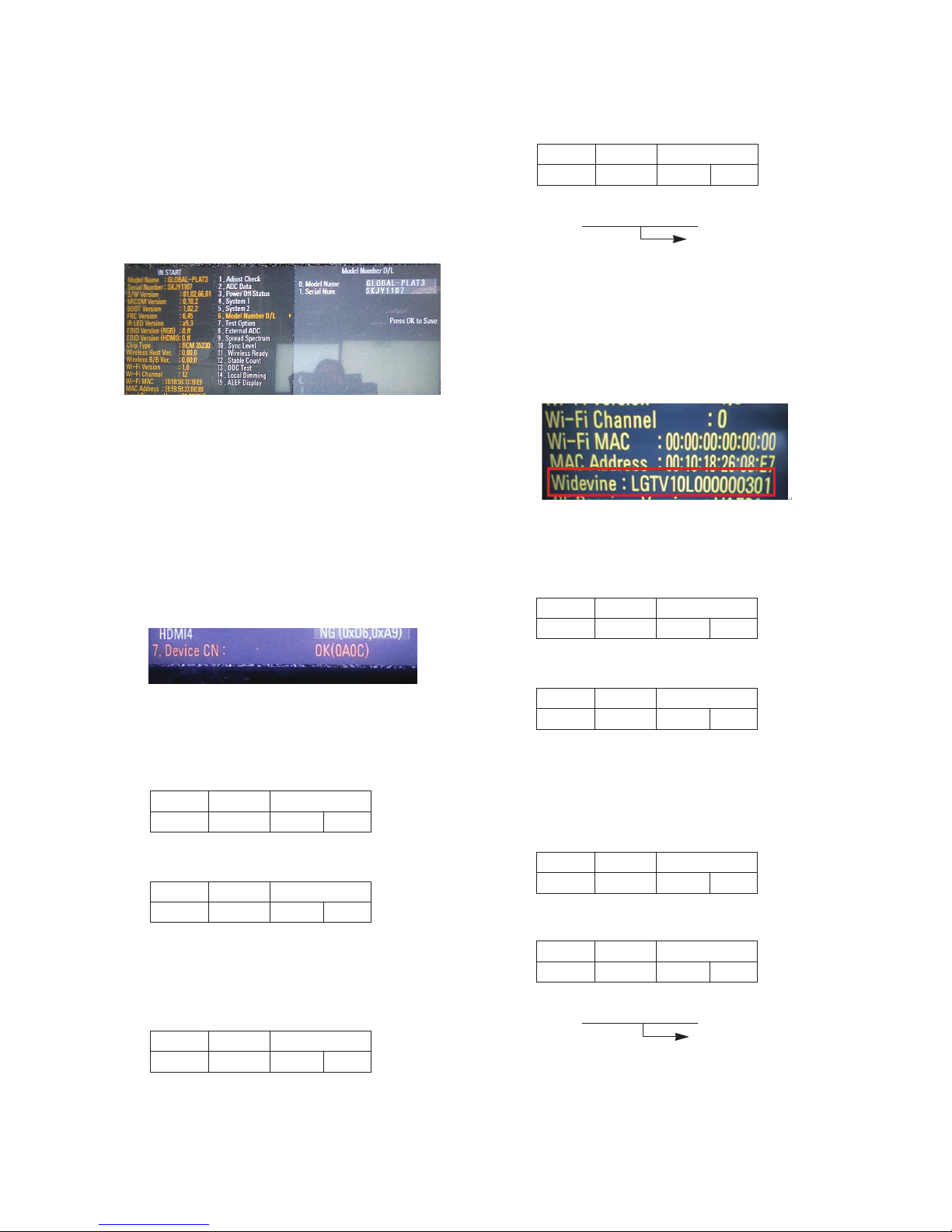
3.5. Model name & Serial number Download
(1) Model name & Serial number D/L
A Press “Power on” key of service remote control.
(Baud rate : 115200 bps)
A Connect RS232 Signal Cable to RS-232 Jack.
A Write Serial number by use RS-232.
A Must check the serial number at Instart menu.
(2) Method & notice
A. Serial number D/L is using of scan equipment.
B. Setting of scan equipment operated by Manufacturing
Technology Group.
C.Serial number D/L must be conformed when it is
produced in production line, because serial number D/L
is mandatory by D-book 4.0
SET PC
- 12 -
LGE Internal Use OnlyCopyright © 2011 LG Electronics. Inc. All rights reserved.
Only for training and service purposes
* Manual Download (Model Name and Serial Number)
If the TV set is downloaded by OTA or service man,
sometimes model name or serial number is initialized.(Not
always)
There is impossible to download by bar code scan, so It
need Manual download.
a. Press the ‘instart’ key of ADJ remote control.
b. Go to the menu ‘5.Model Number D/L’ like below photo.
c. Input the Factory model name(ex 42LW950-ZA) or Serial
number like photo.
d. Check the model name Instart menu -> Factory name
displayed (ex 42LW750S-ZA)
e. Check the Diagnostics (DTV country only) -> Buyer model
displayed (ex 42LW750S-ZA)
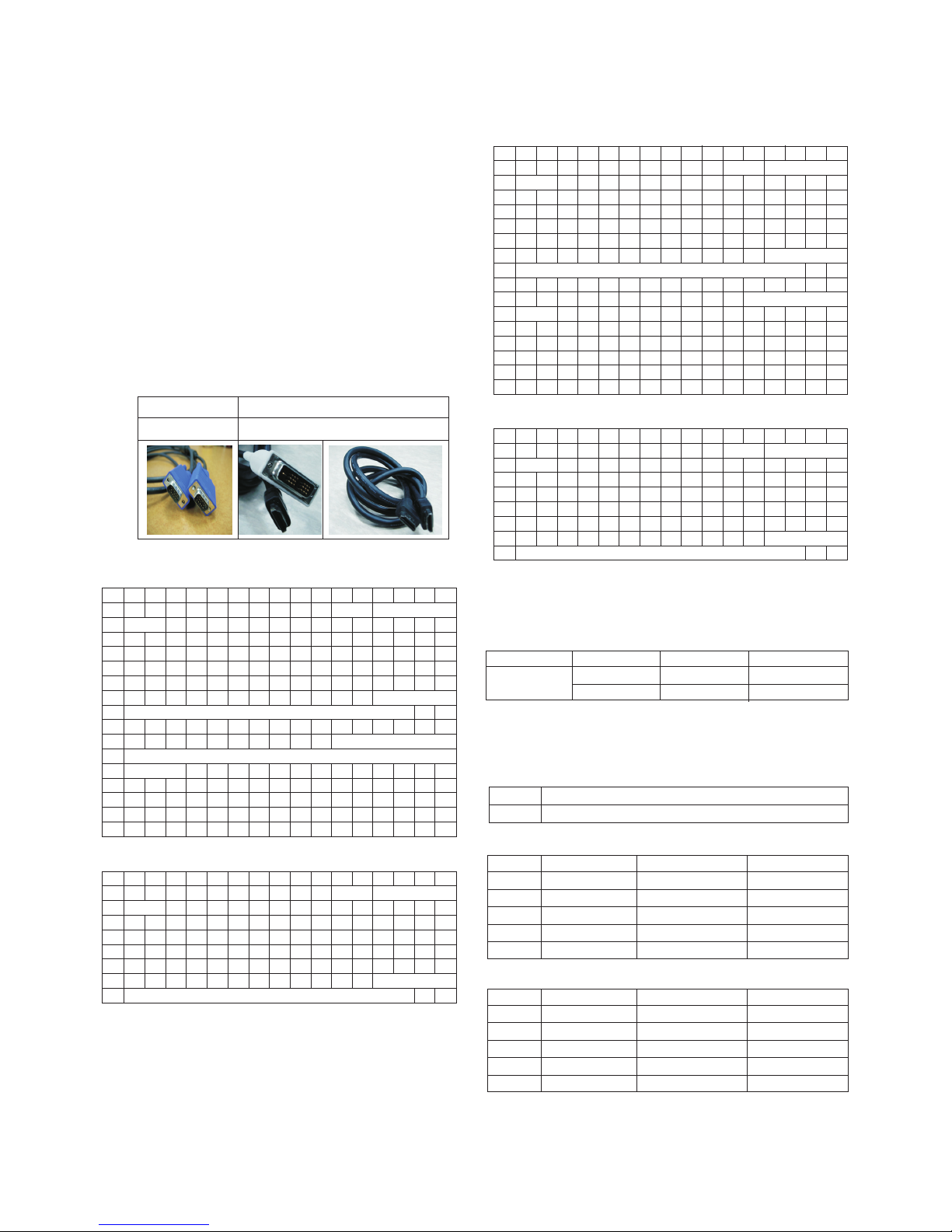
3.6. CI+ Key Download method
3.6.1. Download Procedure
(1) Press “Power on” key of a Service remote control.
(Baud rate : 115200 bps)
(2) Connect RS232-C Signal Cable.
(3) Write CI+ key through RS-232-C.
(4) Check whether the key was downloaded or not at ‘In Start’
menu. (Refer to below).
=> Check the Download to CI+ Key value in LGset.
3.6.2. Check the method of CI+ Key value
(1) Check the method on Instart menu.
(2) Check the method of RS232C Command.
1) into the main ass’y mode (RS232 : aa 00 00)
2) Check the key download for transmitted command
(RS232 : ci 00 10)
3) Result value
- normally status for download : OKx
- abnormally status for download : NGx
3.6.3. Check the method of CI+ Key value (RS232)
1) Into the main ass’y mode (RS232 : aa 00 00)
2) Check the method of CI+ key by command (RS232 : ci
00 20)
3) Result value
i 01 OK 1d1852d21c1ed5dcx
3.7. Widevine Key Download method
3.7.1. Widevine key Download
(1) Press “Power on” key of a Service remote control.
(Baud rate : 115200 bps)
(2) Connect RS232-C Signal Cable.
(3) Write Widevine key through RS-232-C.
(4) Check whether the key was downloaded or not at ‘In Start’
menu. (Refer to below).
=> Check the Download to Widevine Key value in LGset.
3.7.2. Check the method of Widevine key value.
(1) Check the method on Instart menu.
(2) Check the method of RS232C Command.
1) Into the main assembly mode (RS232 : aa 00 00)
2) Check the key download for transmitted command
(RS232 : ci 00 10)
3) Result value
- normally status for download : OKx
- abnormally status for download : NGx
3.7.3. Check the method of Widevine Key value (RS232)
1) Into the main ass’y mode (RS232 : aa 00 00)
2) Check the method of Widevine key by command
(RS232 : ci 00 20)
3) Result value
i 01 OK 1d1852d21c1ed5dcx
CMD 1 CMD 2 Data 0
AA00
CMD 1 CMD 2 Data 0
CI10
CMD 1 CMD 2 Data 0
AA00
CMD 1 CMD 2 Data 0
CI20
CMD 1 CMD 2 Data 0
CI20
CI+ key Value
CMD 1 CMD 2 Data 0
AA00
CMD 1 CMD 2 Data 0
CI10
CMD 1 CMD 2 Data 0
AA00
Widevine key Value
- 13 -
LGE Internal Use OnlyCopyright © 2011 LG Electronics. Inc. All rights reserved.
Only for training and service purposes
3.8. Mac+Widevine+GP3 BCM CI+ download
3.8.1. Connect: PCBA Jig-> RS-232C Port== PC-> RS-232C Port
3.8.2. MAC Address, CI Plus key and Widevine Key write
11Y LCD TV + MAC + Widevine + GP3_BCM CI Plus
(1) Equipment setting
- Play file: keydownload.exe
- Select the download items.(MARLIN)
(2) Communication Prot connection
- Key Write : Com 1,2,3,4 and 115200(Baudrate)
- Barcode : Com 1,2,3,4 and 9600(Baudrate)
(3) Mode check: Online Only
(4) Check the test process: DETECT -> MAC -> CI ->
WIDEVINE
(5) Play: START
(6) Result: Ready, Test, OK or NG
3.9. LNB voltage and 22KHz tone check
- only for DVB-S/S2 model
(1) Test method
1) Press “Power on” key of a service remote control.
(Baud rate : 115200 bps)
2) Connect cable between satellite ANT and test JIG.
3) Connect RS232-C Signal Cable.
4) Write LNB ON control command through RS-232-C.
5) Check LED light ‘ON’ at 18 V menu.
6) Check LED light ‘ON’ at 22 KHz tone menu.
7) Write LNB OFF control command through RS-232-C.
8) Check LED light ‘OFF’ at 18 V menu.
9) Check LED light ‘OFF’ at 22 KHz tone menu.
(2) RS-232 command for test LNB
(3) Test result
- After send LNB On command, ‘18V LED’ and ‘22KHz
tone LED’ should be ON.
- After send LNB OFF command, ‘18V LED’ and ‘22KHz
tone LED’ should be OFF.
4. Manual Adjustment
4.1. ADC(GP3) Adjustment
4.1.1. Overview
ADC adjustment is needed to find the optimum black level and
gain in Analog-to-Digital device and to compensate RGB
deviation.
4.1.2. Equipment & Condition
(1) Adjust Remote control
(2) 801GF(802B, 802F, 802R) or MSPG925FA Pattern Generator
- Resolution :
480i, 720*480(MSPG-925FA->Model:209, Pattern:65)-480i
1080p, 1920*1080(MSPG-925FA->Model:225, Pattern:65)-1080p
- Pattern : Horizontal 100 % Color Bar Pattern
- Pattern level: 0.7 ± 0.1 Vp-p
- Image
(3) Must use standard cable
4.1.3. Adjust method
* If Adjust ADC is “OTP”, It doesn’t need ADC adjustment.
(GP3-BM)
(1) ADC 480i, 1080p Comp1
1) Check connected condition of Component 1 cable to the
equipment.
2) Give a 480i, 1080p Mode, Horizontal 100% Color Bar
Pattern to Component 1.
(MSPG-925FA -> Model: 209, Pattern: 65) - 480i
(MSPG-925FA -> Model: 225, Pattern: 65) - 1080p
3) Change input mode as Component 1 and picture mode
as “Standard”.
4) Press the In-start Key on the ADJ remote after at least 1
min of signal reception. Then, select 7. External ADC ->
1. COMP 1080p on the menu. Press enter key. The
adjustment will start automatically.
5) If ADC calibration is successful, “ADC RGB Success” is
displayed.
If ADC calibration is failure, “ADC RGB Fail” is displayed.
6) If ADC calibration is failure, after recheck ADC pattern or
condition retry calibration Error message refer to 5).
(2) ADC 1920*1080 RGB
1) Check connected condition of Component & RGB cable
to the equipment
2) Give a 1920*1080 Mode, 100 % Horizontal Color Bar
Pattern to RGB port.
(MSPG-925 Series -> model: 225 , pattern: 65 )
3) Change input mode as RGB and picture mode as “Standard”.
4) Press the In-start key on the Adjustment remote control
after at least 1 min of signal reception. Then, select 7.
External ADC -> 1. COMP 1080p on the menu. Press
enter key. The adjustment will start automatically.
5) If ADC calibration is successful, “ADC RGB Success” is
displayed.
If ADC calibration is failure, “ADC RGB Fail” is displayed.
6) If ADC calibration is failure, after recheck ADC pattern or
condition retry calibration Error message refer to 5).
PCBA Power ON Check
Result
Play
MARLIN Key : MAC + CI + WIDEVINE
Com Port Check
CI + Key Write
WIDEVINE Key Write
MAC Address Write
Command Set ACK
LNB On [A][I][ ][Set ID][ ][30][Cr] [O][K][x] or NG : [N][G][x]
LNB Off [A][I][ ][Set ID][ ][40][Cr] [O][K][x] or NG : [N][G][x]
- 14 -
LGE Internal Use OnlyCopyright © 2011 LG Electronics. Inc. All rights reserved.
Only for training and service purposes
4.2. EDID(The Extended Display Identification
Data)/DDC(Display Data Channel) download
(1) Overview
It is a VESA regulation. A PC or a MNT will display an
optimal resolution through information sharing without any
necessity of user input. It is a realization of “Plug and Play”.
(2) Equipment
- Adjust remote control
- Since embedded EDID data is used, EDID download JIG,
HDMI cable and D-sub cable are not need.
(3) Download method
1) Press ADJ key on the Adjustment remote control, then
select “10.EDID D/L”, By pressing Enter key, enter EDID
D/L menu.
2) Select [Start] button by pressing Enter key, HDMI1/
HDMI2/ HDMI3/ RGB are Writing and display OK or NG.
(4) EDID DATA_3D
A HDMI
A RGB
(5) EDID DATA_2D
A HDMI
A RGB
A Reference
- HDMI1 ~ HDMI4 / RGB
- In the data of EDID, bellows may be different by S/W or
Input mode.
ⓐ Product ID
ⓑ Serial No. : Controlled on product line
ⓒ Month, Year: Controlled on production line:
ex) Monthly : ‘01’ -> ‘01’
Year : ‘2010’ -> ‘14’
ⓓ Model Name(Hex):
ⓔ Checksum: Changeable by total EDID data._3D
ⓔ Checksum: Changeable by total EDID data._2D
D-sub to D-sub DVI-D to HDMI or HDMI to HDMI
For HDMI EDIDFor Analog EDID
0x00 0x01 0x02 0x03 0x04 0x05 0x06 0x07 0x08 0x09 0x0A 0x0B 0x0C0x0D 0x0E 0x0F
0x00 0 FF FF FF FF FF FF 0 1E 6D ⓐⓑ
0x01 ⓒ 1 3 8010 9 780AEE91A3544C9926
0x02 0F 50 54 A1 8 0 71 40 81 C0 81 0 81 80 95 0
0x03 90 40 A9 C0 B3 0 2 3A 80 18 71 38 2D 40 58 2C
0x04 45 0 A0 5A 0 0 0 1E 66 21 50 B0 51 0 1B 30
0x05 40 70 36 0 A0 5A 0 0 0 1E 0 0 0 FD 0 39
0x06 3F 1F 52 10 0 0A 20 20 20 20 20 20 ⓓ
0x07 ⓓ 1 ⓔ1
0x00 2 3 37 F1 4E 10 1F 84 13 5 14 3 2 12 20 21
0x01 22 15 1 26 15 7 50 9 57 7 ⓕ
0x02 ⓕ
0x03 ⓕ E3 5 3 1 1 1D 80 18 71 1C 16 20 58
0x04 2C 25 0 A0 5A 0 0 0 9E 1 1D 0 80 51 D0 1A
0x05 20 6E 88 55 0 A0 5A 0 0 0 1A 2 3A 80 18 71
0x06 38 2D 40 58 2C 45 0 A0 5A 0 0 0 1E 0 0 0
0x07 0 0 0 0 0 0 0 0 0 0 0 0 0 0 0 ⓔ2
0x00 0x01 0x02 0x03 0x04 0x05 0x06 0x07 0x08 0x09 0x0A 0x0B 0x0C0x0D 0x0E 0x0F
0x00 0 FF FF FF FF FF FF 0 1E 6D ⓐⓑ
0x01 ⓒ 1 3 68 10 9 780AEE91A3544C99 26
0x02 0F 50 54 A1 8 0 71 40 81 C0 81 0 81 80 95 0
0x03 90 40 A9 C0 B3 0 2 3A 80 18 71 38 2D 40 58 2C
0x04 45 0 A0 5A 0 0 0 1E 66 21 50 B0 51 0 1B 30
0x05 40 70 36 0 A0 5A 0 0 0 1E 0 0 0 FD 0 3A
0x06 3E 1E 53 10 0 0A 20 20 20 20 20 20 ⓓ
0x07 ⓓ 0 ⓔ3
0x00 0x01 0x02 0x03 0x04 0x05 0x06 0x07 0x08 0x09 0x0A 0x0B 0x0C0x0D 0x0E 0x0F
0x00 0 FF FF FF FF FF FF 0 1E 6D ⓐⓑ
0x01 ⓒ 1 3 68 10 9 780AEE91A3544C9926
0x02 0F 50 54 A1 8 0 71 40 81 C0 81 0 81 80 95 0
0x03 90 40 A9 C0 B3 0 2 3A 80 18 71 38 2D 40 58 2C
0x04 45 0 A0 5A 0 0 0 1E 66 21 50 B0 51 0 1B 30
0x05 40 70 36 0 A0 5A 0 0 0 1E 0 0 0 FD 0 3A
0x06 3E 1E 53 10 0 0A 20 20 20 20 20 20 ⓓ
0x07 ⓓ 0 ⓔ3
0x00 0x01 0x02 0x03 0x04 0x05 0x06 0x07 0x08 0x09 0x0A 0x0B 0x0C0x0D 0x0E 0x0F
0x00 0 FF FF FF FF FF FF 0 1E 6D ⓐⓑ
0x01 ⓒ 1 3 80 10 9 780AEE91A3544C9926
0x02 0F 50 54 A1 8 0 71 40 81 C0 81 0 81 80 95 0
0x03 90 40 A9 C0 B3 0 2 3A 80 18 71 38 2D 40 58 2C
0x04 45 0 A0 5A 0 0 0 1E 66 21 50 B0 51 0 1B 30
0x05 40 70 36 0 A0 5A 0 0 0 1E 0 0 0 FD 0 39
0x06 3F 1F 52 10 0 0A 20 20 20 20 20 20 ⓓ
0x07 ⓓ 1 ⓔ1
0x00 2 3 26 F1 4E 10 1F 84 13 5 14 3 2 12 20 21
0x01 22 15 1 26 15 7 50 9 57 7 67 ⓕ
0x02 ⓕ E3 5 3 1 1 1D 80 18 71 1C 16 20 58 2C
0x03 25 0 A0 5A 0 0 0 9E 1 1D 0 80 51 D0 1A 20
0x04 6E 88 55 0 A0 5A 0 0 0 1A 2 3A 80 18 71 38
0x05 2D 40 58 2C 45 0 A0 5A 0 0 0 1E 66 21 50 B0
0x06 51 0 1B 30 40 70 36 0 A0 5A 0 0 0 1E 0 0
0x07 0 0 0 0 0 0 0 00000000ⓔ2
Model Name HEX EDID Table DDC Function
ALL 0001 0100 Analog
0001 0100 Digital
MODEL MODEL NAME(HEX)
all 00 00 00 FC 00 4C 47 20 54 56 0A 20 20 20 20 20 20 20
INPUT 1 2 3
HDMI1 7F CB X
HDMI2 7F BB X
HDMI3 7F AB X
HDMI4 7F 9B X
RGB X X 98
INPUT 1 2 3
HDMI1 7F D9 X
HDMI2 7F C9 X
HDMI3 7F B9 X
HDMI4 7F A9 X
RGB X X 98
- 15 -
LGE Internal Use OnlyCopyright © 2011 LG Electronics. Inc. All rights reserved.
Only for training and service purposes
ⓕ Vendor Specific(HDMI)_3D
ⓕ Vendor Specific(HDMI)_2D
4.3. White Balance Adjustment
4.3.1. Overview
(1) W/B adj. Objective & How-it-works
(2) Objective: To reduce each Panel’s W/B deviation
(3) How-it-works : When R/G/B gain in the OSD is at 192, it
means the panel is at its Full Dynamic Range. In order to
prevent saturation of Full Dynamic range and data, one of
R/G/B is fixed at 192, and the other two is lowered to find
the desired value.
(4) Adj. condition : normal temperature
1) Surrounding Temperature : 25 ºC ± 5 ºC
2) Warm-up time: About 5 Min
3) Surrounding Humidity : 20 % ~ 80 %
* Before White balance adjustment, Keep power on status.
don’t power off.
* ALEF Header(Module with T-con) supplied as SKD has
White Balance data. (White balance data is stored in
EEPROM of the T-con Board)
It doesn’t need to adjust White balance if “3. Adjust White
Balance” is OK as figure below.
4.3.2. Equipment
1) Color Analyzer: CA-210 (LED Module : CH 14)
2) Adj. Computer(During auto adj., RS-232C protocol is needed)
3) Adjustment remote control
4) Video Signal Generator MSPG-925F 720p/216-Gray
(Model:204, Pattern:80IRE)
-> Only when internal pattern is not available
A Color Analyzer Matrix should be calibrated using CS-1000
4.3.3. Equipment connection MAP
4.3.4. Adj. Command (Protocol)
<Command Format>
- LEN: Number of Data Byte to be sent
- CMD: Command
- VAL: FOS Data value
- CS: Checksum of sent data
- A: Acknowledge
Ex) [Send: JA_00_DD] / [Ack: A_00_okDDX]
A RS-232C Command used during auto-adj.
Ex) wb 00 00 -> Begin white balance auto-adj.
wb 00 10 -> Gain adj.
ja 00 ff -> Adj. data
jb 00 c0
...
...
wb 00 1f -> Gain adj. completed
*(wb 00 20(Start), wb 00 2f(completed)) -> Off-set adj.
wb 00 ff -> End white balance auto-adj.
A Adj. Map
Color Analyzer
Comp uter
Pattern Generator
RS- 232C
RS-232C
RS-232C
Probe
Signal Source
* If TV internal pattern is used, not needed
LEN CMD VAL
CS
RS-232C COMMAND Explanation
[CMD ID DATA]
wb 00 00 Begin White Balance adj.
wb 00 10 Gain adj.(internal white pattern)
wb 00 1f Gain adj. completed
wb 00 20 Offset adj.(internal white pattern)
wb 00 2f Offset adj. completed
wb 00 ff End White Balance adj.(Internal pattern disappears)
ITEM Command Data Range(Hex.) Default(Decimal)
Cmd 1 Cmd 2 Min Max
Cool R-Gain j g 00 C0
G-Gain j h 00 C0
B-Gain j i 00 C0
R-Cut
G-Cut
B-Cut
Medium R-Gain j a 00 C0
G-Gain j b 00 C0
B-Gain j c 00 C0
R-Cut
G-Cut
B-Cut
Warm R-Gain j d 00 C0
G-Gain j e 00 C0
B-Gain j f 00 C0
R-Cut
G-Cut
INPUT MODEL NAME(HEX)
HDMI1 78 03 0C 00 10 00 B8 2D 20 C0 0E 01 40 0A 3C 08 10 18 10 98 10 58 10 38 10
HDMI2 78 03 0C 00 20 00 B8 2D 20 C0 0E 01 40 0A 3C 08 10 18 10 98 10 58 10 38 10
HDMI3 78 03 0C 00 30 00 B8 2D 20 C0 0E 01 40 0A 3C 08 10 18 10 98 10 58 10 38 10
HDMI4 78 03 0C 00 40 00 B8 2D 20 C0 0E 01 40 0A 3C 08 10 18 10 98 10 58 10 38 10
INPUT MODEL NAME(HEX)
HDMI1 67 03 0C 00 10 00 B8 2D
HDMI2 67 03 0C 00 20 00 B8 2D
HDMI3 67 03 0C 00 30 00 B8 2D
HDMI4 67 03 0C 00 40 00 B8 2D

- 16 -
LGE Internal Use OnlyCopyright © 2011 LG Electronics. Inc. All rights reserved.
Only for training and service purposes
4.3.5. Adjustment method
(1) Auto adjustment method
1) Set TV in adjustment mode using POWER ON key.
2) Zero calibrate probe then place it on the center of the
Display.
3) Connect Cable. (RS-232C)
4) Select mode in adj. Program and begin adjustment.
5) When adjustment is complete (OK Sign), check adj.
status pre mode.(Warm, Medium, Cool)
6) Remove probe and RS-232C cable to complete adj.
A W/B Adj. must begin as start command “wb 00 00” , and
finish as end command “wb 00 ff”, and Adj. offset if need.
(2) Manual adjustment method
1) Set TV in Adjustment mode using POWER ON
2) Zero Calibrate the probe of Color Analyzer, then place it
on the center of LCD module within 10 cm of the surface.
3) Press ADJ key -> EZ adjust using adjustment R/C -> 7.
White-Balance then press the cursor to the right key(G).
(When key(G) is pressed 216 Gray internal pattern will
be displayed)
4) One of R Gain / G Gain / B Gain should be fixed at 192,
and the rest will be lowered to meet the desired value.
5) Adj. is performed in COOL, MEDIUM, WARM 3 modes
of color temperature.
A If internal pattern is not available, use RF input. In EZ
Adj. menu 7.White Balance, you can select one of 2
Test-pattern: ON, OFF. Default is inner(ON). By
selecting OFF, you can adjust using RF signal in 216
Gray pattern.
A Adj. condition and cautionary items
1) Lighting condition in surrounding area
Surrounding lighting should be lower 10 lux. Try to
isolate adj. area into dark surrounding.
2) Probe location : Color Analyzer(CA-210) probe should
be within 10 cm and perpendicular of the module
surface (80° ~ 100°)
3) Aging time
- After Aging Start, Keep the Power ON status during 5
Minutes.
- In case of LCD, Back-light on should be checked
using no signal or Full-white pattern.
4.3.6. Reference(White Balance Adj. coordinate and temperature)
A Luminance : 204 Gray
A Standard color coordinate and temperature using CS-1000
(over 26 inch)
A Standard color coordinate and temperature using CA-210
(CH 14)
4.3.7. White balance table
A Module change color coordinate because of aging time.
A Apply under the color coordinate table, for compensated
aging time.
4.4. Wireless function check
Step 1) Connect set and Dongle of Wireless to Cable of HDMI
& TTA 20Pin
Step 2) At OSD of SET, check the message like Fig.3
Step 3) Detach Cable of Wireless Dongle
Mode Color Coordination Temp ∆UV
xy
COOL 0.269 0.273 13000 K 0.0000
MEDIUM 0.285 0.293 9300 K 0.0000
WARM 0.313 0.329 6500 K 0.0000
Mode Color Coordination Temp ∆UV
xy
COOL 0.269 ± 0.002 0.273 ± 0.002 13000 K 0.0000
MEDIUM 0.285 ± 0.002 0.293 ± 0.002 9300 K 0.0000
WARM 0.313 ± 0.002 0.329 ± 0.002 6500 K 0.0000
GP2 Aging Time Cool Medium Warm
(Min.) X Y X Y X Y
269 273 285 293 313 329
1 0-2 279 288 295 308 319 338
2 3-5 278 286 294 306 318 336
3 6-9 277 285 293 305 317 335
4 10-19 276 283 292 303 316 333
5 20-35 274 280 290 300 314 330
6 36-49 272 277 288 297 312 327
7 50-79 271 275 287 295 311 325
8 80-149 270 274 286 294 310 324
9 Over 150 269 273 285 293 309 323
Fig. 1
<Dongle>
Fig. 3 Connect the Dongle
(Dongle Connection Display)
Fig. 2
<Wireless Ready Set>
Connect
- 17 -
LGE Internal Use OnlyCopyright © 2011 LG Electronics. Inc. All rights reserved.
Only for training and service purposes
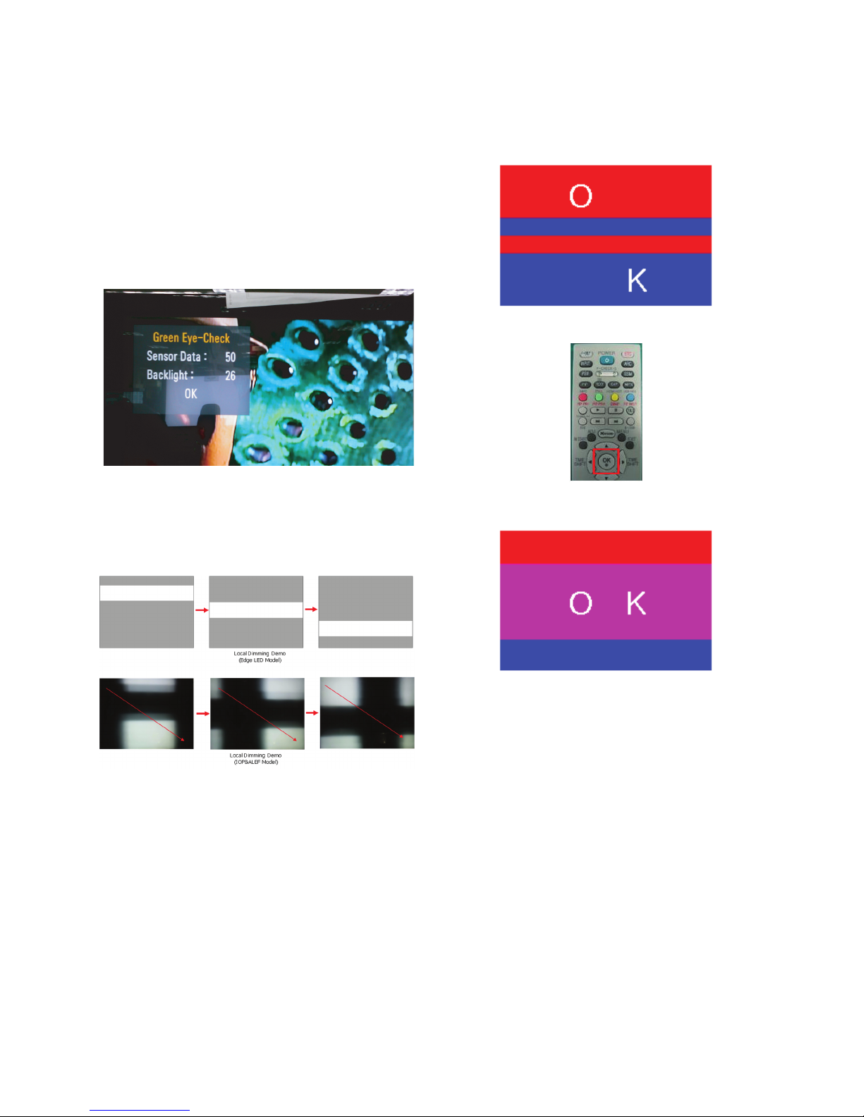
4.5. EYE-Q function check
Step 1) Turn on TV.
Step 2) Press EYE key of Adjustment remote control.
Step 3) Cover the Eye Q II sensor on the front of the using
your hand and wait for 6 seconds.
Step 4) Confirm that R/G/B value is lower than 10 of the “Raw
Data (Sensor data, Back light)”. If after 6 seconds,
R/G/B value is not lower than 10, replace Eye Q II
sensor.
Step 5) Remove your hand from the Eye Q II sensor and wait
for 6 seconds.
Step 6) Confirm that “ok” pop up. If change is not seen,
replace Eye Q II sensor.
4.6. Local Dimming Function Check
(1) Turn on TV.
(2) At the Local Dimming mode, module Edge Backlight
moving Top to Bottom Back light of IOP module moving.
(3) Confirm the Local Dimming mode.
(4) Press “exit” key
4.7. Magic Motion Remote control test
- Equipment : RF Remote control for test, IR-KEY-Code
Remote control for test
- You must confirm the battery power of RF-Remote control
before test.(recommend that change the battery per every lot)
- Sequence (test)
1) if you select the ‘start key(Mute)’ on the Remote control,
you can pairing with the TV SET.
2) You can check the cursor on the TV Screen, when select
the ‘OK’ key on the Remote control.
3) You must remove the pairing with the TV Set by select
‘Vol+(STOP)’ key on the Remote control.
4.8. 3D function test
(Pattern Generator MSHG-600, MSPG-6100 [Support HDMI 1.4])
* HDMI mode No. 872, pattern No. 83)
1) Please input 3D test pattern like below
2) When 3D OSD appear automatically, then select OK key.
3) Don’t wear a 3D Glasses, Check the picture like below.
4.9. LNB voltage and 22 KHz tone check
(only for DVB-S/S2 model)
(1) Test method
1) Set TV in Adj. mode using POWER ON.
2) Connect cable between satellite ANT and test JIG.
3) Press Yellow Key (ETC+SWAP) in Adj Remote control to
make LNB on.
4) Check LED light ‘ON’ at 18V menu.
5) Check LED light ‘ON’ at 22KHz tone menu.
6) Press Blue Key (ETC+PIP INPUT) in Adjustment remote
control to make LNB off.
7) Check LED light ‘OFF’ at 18 V menu.
8) Check LED light ‘OFF’ at 22 KHz tone menu.
(2) Test result
- After press LNB On key, ‘18 V LED’ and ‘22 KHz tone
LED’ should be ON.
- After press LNB OFF key, ‘18 V LED’ and ‘22 KHz tone
LED’ should be OFF.
- 18 -
LGE Internal Use OnlyCopyright © 2011 LG Electronics. Inc. All rights reserved.
Only for training and service purposes
4.10. Option selection per country
(1) Overview
- Option selection is only done for models in Non-EU.
- Applied model: LD03D/03E Chassis applied EU model.
(2) Method
1) Press ADJ key on the Adjustment remote control, then
select Country Group Menu.
2) Depending on destination, select Country Group Code
04 or Country Group EU then on the lower Country
option, select US, CA, MX. Selection is done using +, or
GF KEY.
4.11. Tool Option selection
- Method : Press Adj. key on the Adjustment remote rontrol,
then select Tool option.
4.12. Ship-out mode check(In-stop)
After final inspection, press IN-STOP key of the Adjustment
remote control and check that the unit goes to Stand-by mode.
5. GND and Internal Pressure check
5.1. Method
1) GND & Internal Pressure auto-check preparation
- Check that Power Cord is fully inserted to the SET.
(If loose, re-insert)
2) Perform GND & Internal Pressure auto-check
- Unit fully inserted Power cord, Antenna cable and A/V
arrive to the auto-check process.
- Connect D-terminal to AV JACK TESTER
- Auto CONTROLLER(GWS103-4) ON
- Perform GND TEST
- If NG, Buzzer will sound to inform the operator.
- If OK, changeover to I/P check automatically.
(Remove CORD, A/V form AV JACK BOX)
- Perform I/P test
- If NG, Buzzer will sound to inform the operator.
- If OK, Good lamp will lit up and the stopper will allow the
pallet to move on to next process.
5.2. Checkpoint
• TEST voltage
- GND: 1.5 KV/min at 100 mA
- SIGNAL: 3 KV/min at 100 mA
• TEST time: 1 second
• TEST POINT
- GND TEST = POWER CORD GND & SIGNAL CABLE
METAL GND
- Internal Pressure TEST = POWER CORD GND & LIVE &
NEUTRAL
• LEAKAGE CURRENT: At 0.5 mArms
6. Audio
Measurement condition:
1. RF input: Mono, 1 KHz sine wave signal, 100 % Modulation
2. CVBS, Component: 1 KHz sine wave signal 0.4 Vrms
3. RGB PC: 1 KHz sine wave signal 0.7 Vrms
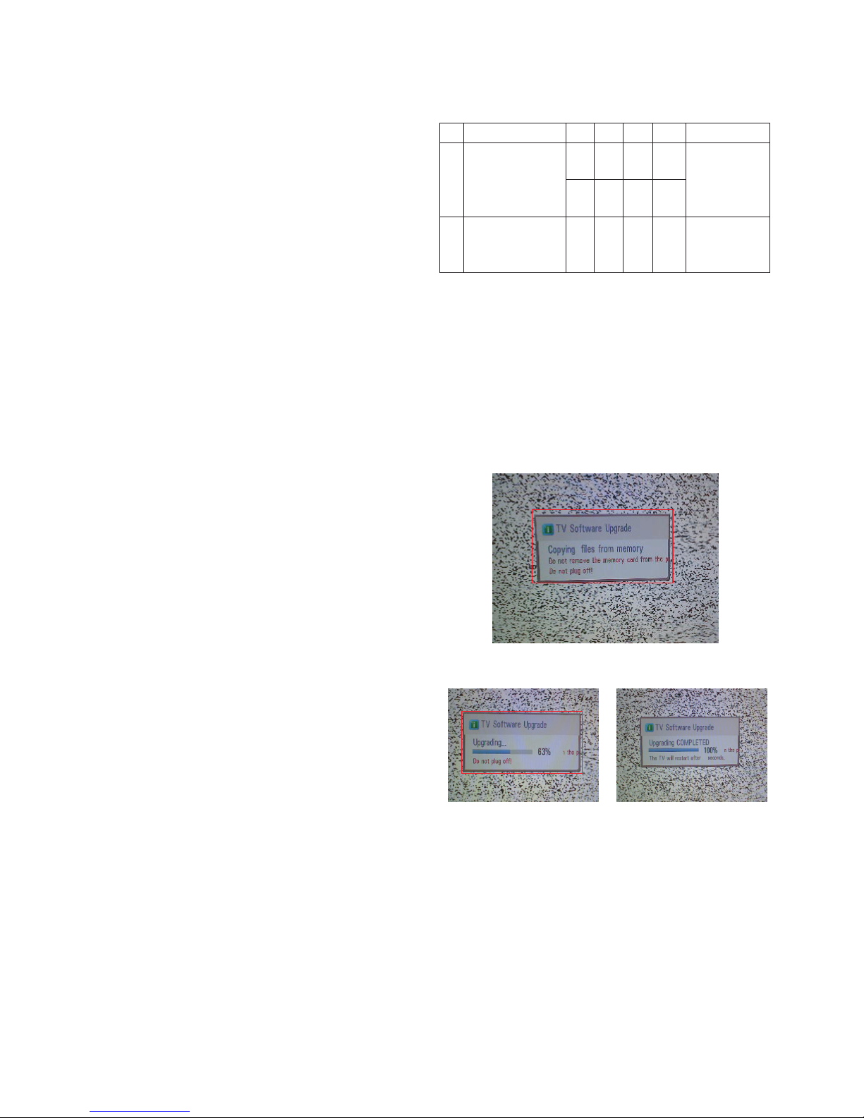
7. USB S/W Download (option, Service only)
1) Put the USB Stick to the USB socket.
2) Automatically detecting update file in USB Stick.
- If your downloaded program version in USB Stick is Low,
it didn’t work. But your downloaded version is High, USB
data is automatically detecting.
3) Show the message “Copying files from memory”.
4) Updating is starting.
5) Updating Completed, The TV will restart automatically
6) If your TV is turned on, check your updated version and
Tool option. (explain the Tool option, next stage)
* If downloading version is more high than your TV have, TV
can lost all channel data. In this case, you have to channel
recover. if all channel data is cleared, you didn’t have a
DTV/ATV test on production line.
* After downloading, have to adjust TOOL OPTION again.
1) Push “IN-START” key in service remote control.
2) Select “Tool Option 1” and push “OK” key.
3) Punch in the number.(Each model has their number.)
No. Item Min. Typ. Max. Unit
1. Audio practical max 9 10 12 W EQ Off
Output, L/R AVL Off
(Distortion=10 % 0.5 Vrms Clear Voice Off
max Output)
2. Speaker (8 Ω 9 10.0 12.0 W EQ On
Impedance) AVL On
Clear Voice On
- 19 -
LGE Internal Use OnlyCopyright © 2011 LG Electronics. Inc. All rights reserved.
Only for training and service purposes
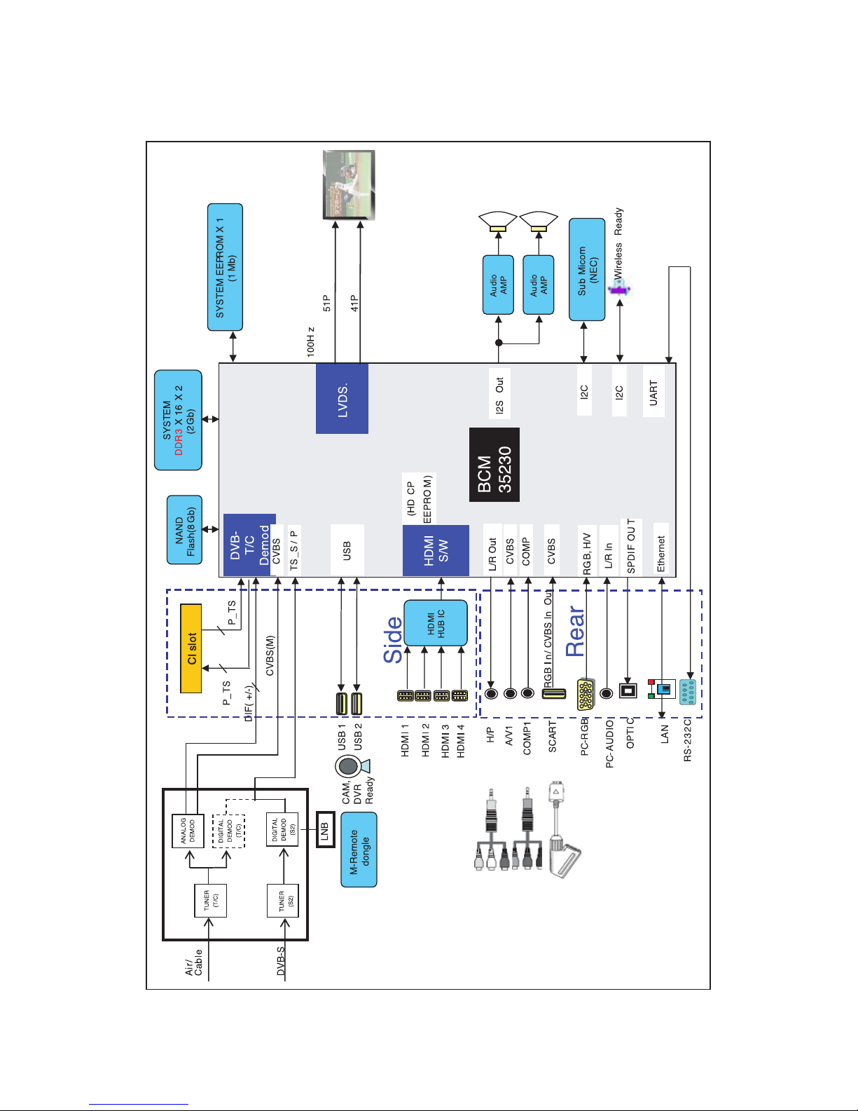
BLOCK DIAGRAM
- 20 -
LGE Internal Use OnlyCopyright LG Electronics. Inc. All rights reserved.
Only for training and service purposes
500
510
300
A5
A2
A21
A10
LV2
LV1
120
800
200
400
900
910
530
540
521
710
700
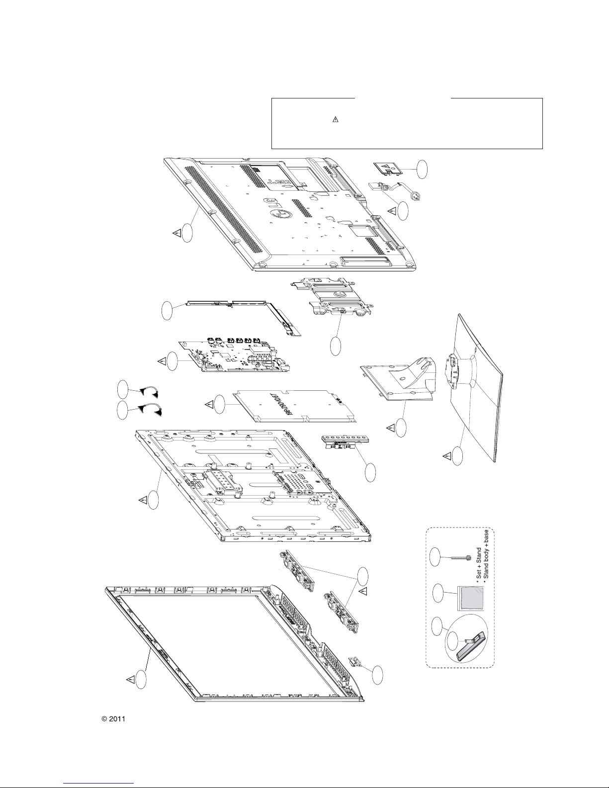
EXPLODED VIEW
Many electrical and mechanical parts in this chassis have special safety-related characteristics. These
parts are identified by in the Schematic Diagram and EXPLODED VIEW.
It is essential that these special safety parts should be replaced with the same components as
recommended in this manual to prevent X-RADIATION, Shock, Fire, or other Hazards.
Do not modify the original design without permission of manufacturer.
IMPORTANT SAFETY NOTICE
THE SYMBOL MARK OF THIS SCHEMETIC DIAGRAM INCORPORATES
SPECIAL FEATURES IMPORTANT FOR PROTECTION FROM X-RADIATION.
FILRE AND ELECTRICAL SHOCK HAZARDS, WHEN SERVICING IF IS
ESSENTIAL THAT ONLY MANUFATURES SPECFIED PARTS BE USED FOR
THE CRITICAL COMPONENTS IN THE SYMBOL MARK OF THE SCHEMETIC.
NAND_DATA[0]
NAND_DATA[1]
CI_ADDR[12]
NAND_DATA[2]
CI_ADDR[2]
NAND_DATA[1]
NAND_DATA[3]
CI_ADDR[7]
CI_ADDR[13]
CI_ADDR[14]
NAND_DATA[4]
NAND_DATA[2]
NAND_DATA[3]
NAND_DATA[7]
NAND_DATA[5]
CI_ADDR[8]
NAND_DATA[7]
NAND_DATA[0]
NAND_DATA[6]
CI_ADDR[4]
CI_ADDR[9]
NAND_DATA[4]
CI_ADDR[3]
NAND_DATA[6]
NAND_DATA[5]
CI_ADDR[10]
CI_ADDR[11]
CI_ADDR[5]
CI_ADDR[6]
R185 0
TXA0N
SOC_RESET
TXBCLKP
R151
0
16Gbit
R147
1K
TXD0P
R170
10K
SDA2_3.3V
HDMI_ARC
R172
4.7K
OPT
TXD1P
C103
0.1uF
54MHz_XTAL_P
R183
10K
C101
0.1uF
TXA1P
DTV/MNT_V_OUT
TXC0P
TXC1P
R180
10K
TXDCLKN
TXA3N
R115
10K
R132 4.7K
R120
10K
SCL0_3.3V
TXACLKN
+3.3V_Normal
R116
10K
OPT
NAND_DATA[6]
+3.3V_Normal
HDMI_CLK+
R118
10K
R150
1K
NAND_WEb
+3.3V_Normal
P101
TJC2508-4A
1
VCC
2
SCL
3
SDA
4
GND
TXD2P
NAND_DATA[5]
C106
4.7uF
CI_ADDR[8]
SC_ID
NAND_CEb2
+3.3V_Normal
R145 22
OPT
R157
10K
OPT
CI_ADDR[12]
R169
0
CI_ADDR[7]
C112 0.1uF
TXB4P
R107 2.7K
C107
33pF
50V
DVB_S
TXD1N
NAND_CEb
NAND_RBb
R101
4.7K
R124
1K
OPT
C119
0.1uF
16V
NAND_CLE
TXB2N
+3.3V_Normal
TXD4P
5V_HDMI_2
NAND_CEb2
C104 10uF
10V
TXA1N
TXB3N
BSS83
Q101
SBD
G
NAND_DATA[3]
HDMI_CLK-
R176
10K
SDA0_3.3V
R111
10K
OPT
R191 33
TXD3P
TXB0P
R154
10K
OPT
BCM_RX
HDMI_RX2+
TXC2P
R103
4.7K
OPT
+3.3V_Normal
TXD2N
TXCCLKP
C102
4700pF
R198
10K
C111 0.01uF
NAND_ALE
TXBCLKN
NAND_DATA[0-7]
TXCCLKN
R179
10K
OPT
HDMI_RX1+
R117
10K
OPT
R135
33
C108
33pF
50V
DVB_S
R177
10K
FLASH_WP
TXA4N
R165
10K
R195
4.7K
IC103
M24M01-HRMN6TP
BCM_NVM_1M
3
E2
2
E1
4
VSS
1
NC
5
SDA
6
SCL
7
WP
8
VCC
NAND_DATA[7]
R173
4.7K
TXB4N
R190 33
NAND_DATA[0-7]
NAND_WEb
R196
10K
NAND_CEb
R108 10K
CI_ADDR[4]
+3.3V_Normal
NAND_REb
R156
1K
/CI_CE1
R155
10K
A_DIM
R153
1K
TXA3P
HDMI_RX1-
NAND_DATA[0]
5V_HDMI_1
R194
2.7K
R127
10K
OPT
NAND_CLE
R125
1K
R178
10K
OPT
C105
2.2uF
10V
CI_ADDR[13]
C109
33pF
50V
54MHz_XTAL_N
R159
1K
5V_HDMI_4
R128
10K
/PCM_WAIT
+3.3V_Normal
HDMI_RX0-
CI_ADDR[3]
BCM_TX
C110
33pF
50V
TXB1P
+3.3V_Normal
R184
10K
OPT
NAND_ALE
R144 22
OPT
TXA0P
R122
10K
SCL2_3.3V
NAND_DATA[1]
+3.3V_Normal
R106
3K
R119
10K
OPT
TXC3N
R175
10K
OPT
SCL3_3.3V
HDMI_RX0+
R123
10K
OPT
R167
10K
OPT
CI_ADDR[2]
R130
2K
OPT
R110
1.5K
R113
10K
R193
10K
R181
10K
OPT
R112
10K
TXACLKP
R148
0
16Gbit
TXB3P
R182
10K
TXC4N
R163
1K
+3.3V_Normal
LNB_INT
R114
10K
OPT
R140
560
1%
R158
10K
R162
1K
TXA2P
TXA2N
NAND_RBb
NAND_DATA[4]
R136 33
R149 0
16Gbit
R143 22
OPT
TXC4P
R186 0
BSS83
Q102
SBD
G
NAND_DATA[2]
R139 0
TXB1N
CI_ADDR[11]
CI_ADDR[9]
5V_HDMI_3
+3.3V_Normal
R166
1K
RGB_DDC_SCL
+3.3V_Normal
TXD4N
TXC1N
54MHz_XTAL_P
TXDCLKP
R171
10K
OPT
TXC2N
TXC0N
R160
10K
OPT
TXB0N
NAND_REb
TXC3P
CI_ADDR[6]
R168
10K
PCM_5V_CTL
R189
1M
OPT
+3.3V_Normal
R141 4.7K
TXD0N
54MHz_XTAL_N
R192
10K
OPT
R14610K
C118
0.1uF
16V
+3.3V_Normal
+3.3V_Normal
/CI_CE2
TXA4P
R164
10K
OPT
+3.3V_Normal
R161
10K
R142 22
OPT
R188
10K
R187
10K
OPT
SDA3_3.3V
NAND_CLE
R109
1.5K
FLASH_WP
TXB2P
+3.3V_Normal
TXD3N
+3.3V_Normal
CI_ADDR[2-14]
HDMI_RX2-
R174
4.7K
OPT
RGB_DDC_SDA
NAND_ALE
R126
1.2K
R129
1.2K
R121
1.2K
R131
1.2K
R199 22
R197 22
R105
4.7K
R104
4.7K
IC102
TC58DVG3S0ETA00
NAND_8Gbit
26
NC_17
27
NC_18
28
NC_19
29
I/O1
30
I/O2
31
I/O3
32
I/O4
33
NC_20
34
NC_21
35
NC_22
36
VSS_2
37
VCC_2
38
NC_23
39
PSL
40
NC_24
41
I/O5
42
I/O6
43
I/O7
44
I/O8
45
NC_25
46
NC_26
47
NC_27
48
NC_28
17
ALE
3
NC_3
6
NC_6
16
CLE
15
NC_10
14
NC_9
13
VSS_1
12
VCC_1
11
NC_8
10
NC_7
9
CE
8
RE
7
RY/BY
4
NC_4
5
NC_5
25
NC_16
24
NC_15
23
NC_14
2
NC_2
22
NC_13
21
NC_12
1
NC_1
20
NC_11
19
WP
18
WE
IC102-*1
TH58DVG4S0ETA20
DEV_NAND_16Gbit
26
NC_15
27
NC_16
28
NC_17
29
I/O1
30
I/O2
31
I/O3
32
I/O4
33
NC_18
34
NC_19
35
NC_20
36
VSS_2
37
VCC_2
38
NC_21
39
PSL
40
NC_22
41
I/O5
42
I/O6
43
I/O7
44
I/O8
45
NC_23
46
NC_24
47
NC_25
48
NC_26
17
ALE
3
NC_3
6
RY/BY2
16
CLE
15
NC_8
14
NC_7
13
VSS_1
12
VCC_1
11
NC_6
10
CE2
9
CE1
8
RE
7
RY/BY1
4
NC_4
5
NC_5
25
NC_14
24
NC_13
23
NC_12
2
NC_2
22
NC_11
21
NC_10
1
NC_1
20
NC_9
19
WP
18
WE
LGE35230(BCM35230KFSBG)
IC101
BCM_WITHOUT_CAP
HDMI0_CLKN
B5
HDMI0_CLKP
C5
HDMI0_D0N
A4
HDMI0_D0P
B4
HDMI0_D1N
A3
HDMI0_D1P
B3
HDMI0_D2N
A2
HDMI0_D2P
B2
CEC
W2
DDC0_SCL
V4
DDC0_SDA
W4
HDMI0_HTPLG_IN
V3
HDMI0_HTPLG_OUT
V2
HDMI0_ARC
D13
HDMI0_RESREF
E6
TXOUT0_L0N
AE27
TXOUT0_L0P
AE28
TXOUT0_L1N
AF27
TXOUT0_L1P
AF28
TXOUT0_L2N
AG27
TXOUT0_L2P
AG28
TXCLK_LN
AE26
TXCLK_LP
AF26
TXOUT0_L3N
AH27
TXOUT0_L3P
AG26
TXOUT0_L4N
AF25
TXOUT0_L4P
AE25
TXOUT0_U0N
AH26
TXOUT0_U0P
AG25
TXOUT0_U1N
AE24
TXOUT0_U1P
AD24
TXOUT0_U2N
AH25
TXOUT0_U2P
AF24
TXCLK_UN
AE23
TXCLK_UP
AD23
TXOUT0_U3N
AG24
TXOUT0_U3P
AF23
TXOUT0_U4N
AC22
TXOUT0_U4P
AD22
TXOUT1_L0N
AG23
TXOUT1_L0P
AH23
TXOUT1_L1N
AE22
TXOUT1_L1P
AE21
TXOUT1_L2N
AF22
TXOUT1_L2P
AH22
TXCLK1_LN
AG22
TXCLK1_LP
AF21
TXOUT1_L3N
AG21
TXOUT1_L3P
AF20
TXOUT1_L4N
AD21
TXOUT1_L4P
AC21
TXOUT1_U0N
AG20
TXOUT1_U0P
AH20
TXOUT1_U1N
AD19
TXOUT1_U1P
AE19
TXOUT1_U2N
AF19
TXOUT1_U2P
AH19
TXCLK1_UN
AE18
TXCLK1_UP
AD18
TXOUT1_U3N
AG19
TXOUT1_U3P
AF18
TXOUT1_U4N
AG18
TXOUT1_U4P
AF17
LT0VCAL_MONITOR
AC18
GPIO_BL_ON
AH16
BL_PWM/GPIO
AG16
LGE35230(BCM35230KFSBG)
IC101
BCM_WITHOUT_CAP
TVM_XTALIN
AG6
TVM_XTALOUT
AF6
IRRXDA
V5
FP_IN0
AB4
FP_IN1
Y4
SPARE_ADC1
AA4
SPARE_ADC2
Y5
FS_IN1
AB2
FS_IN2
AB5
VGA_SDA
U3
VGA_SCL
U2
RDA
Y2
TDA
Y1
BSCDATAA
AA3
BSCCLKA
AA2
RDB/GPIO
H3
TDB/GPIO
H2
BSC_S_SCL
H4
BSC_S_SDA
H5
NMIB
F25
POWER_CTRL
W5
AON_HSYNC
U5
AON_VSYNC
U4
AON_GPIO_36
W3
AON_GPIO_37
W1
AON_RESETOUTB
AB6
TVM_BYPASS
Y6
RESETB
Y3
RESETOUTB
G24
TMODE
J6
TESTEN
W6
VDAC_VREG
F7
VDAC_RBIAS
E7
FAD_7
AB1
FAD_6
AB3
FAD_5
AC1
FAD_4
AC2
FAD_3
AC3
FAD_2
AD2
FAD_1
AD3
FAD_0
AE2
FALE
AG1
FCEB_0
AF1
FCEB_1
AC5
FCEB_2
AE6
FCEB_3
AG5
NFWPB
AF3
FWE
AG2
FRD
AE3
FRDYB
AA5
FA_0
AF2
FA_1
AE1
FA_2
AC4
FA_3
AD5
FA_4
AD4
FA_5
AE4
FA_6
AE5
FA_7
AD6
FA_8
AH3
FA_9
AF4
FA_10
AH4
FA_11
AG4
FA_12
AF5
FA_13
AG3
FA_14
AH2
FA_15
AH5
TRSTB
AD15
TDI/GPIO
AF14
TDO
AH14
TMS/GPIO
AD14
TCK/GPIO
AG14
DINT/GPIO
AC16
AVS_VFB
AH7
AVS_VSENSE
AG7
AVS_RESETB
AD7
AVS_NDRIVE_1
AF7
AVS_PDRIVE_1
AH8
VDAC_1
C6
VDAC_2
D7
X101
54MHz
EAW58812611
SUNNY ELECTRONICS CORPORATION
CRYSTAL_BCM_Sunny
4
GND_21X-TAL_1
2
GND_1
3
X-TAL_2
X101-*1
54MHz
CRYSTAL_BCM_Lihom
EAW60763703
LIHOM CO., LTD.
4
GND_2
1
X-TAL_1
2
GND_13X-TAL_2
X101-*2
54MHz
CRYSTAL_BCM_KDS
DAISHINKU CORPORATION.
EAW58239604
4
GND_2
1
X-TAL_1
2
GND_13X-TAL_2
IC103-*1
AT24C256C-SSHL-T
BCM_NVM_256K
3
A2
2
A1
4
GND
1
A0
5
SDA
6
SCL
7
WP
8
VCC
C114
12pF
50V
C113
12pF
50V
SRST
SRST
MAIN & NAND FLASH
BBS CONNECT
Write Protection
- High : Normal Operation
- Low : Write Protection
NAND_DATA[0]:
0: System is LITTLE endian (O)
1: System is BIG endian
CI_ADDR[7]:
0: Disable EDID automatic Downloading from Flash (O)
1: Enable EDID automatic Downloading from Flash
NAND_DATA[6] :
0: Disable OSC clock output on chip Pin (O)
1: Enable OSC clock output on chip pin.
CI_ADDR[6]:
0: Host MIPS run at 500 MHz (O)
1: Host MIPS run at 250 MHz
NAND_CLE:
0: Differential Oscillators TVM not bypassed (O)
1: Differential Oscillators TVM bypassed
NAND_DATA[4]:
0: 27MHz TVM Crystal Frequency
1: 54MHz TVM Crystal Frequency (O)
Write Protection
- Low : Normal Operation
- High : Write Protection
000 = ECC disabled
001 = ECC 1-bit repair
010 = ECC 4-bit BCH (O)
011 = ECC 8-bit BCH, 27 byte spare
100 = ECC 12-bit BCH, 27 byte spare
101 = ECC 8-bit BCH, 16 byte spare
110, 111 = Reservedd
NAND ECC (FA3, FA2, FALE)
BCM REFRENCE is 562ohm
A8’h
FOR HDMI STANDARD
APPLY ONLY WHEN CONNECT TO PULL-UP GPIO
BCM35230
01
CI_ADDR[9],CI_ADDR[11],CI_ADDR[12],CI_ADDR[13]
TVM Crystal oscillator bias/gain control
0000: 210uA
0001: 390uA
0010: 570uA
0011: 730uA
0100: 890uA (O)
0111: 1290uA
1000: 1416uA
1111: 2196uA
0101, 0110, 1001, 1010, 1011, 1100, 1101, 1110: Reserved
CI_ADDR[8]:
0: RESETOUTb (in On/Off only) stay asserted until software releases them.
1: Fix amount of delay for de-assertion on RESETOUTb (in On/IOff only)
at end of RESETb pulse (O)
NAND_DATA[3]:
0: MIPS will boot from external flash (O)
1: MIPS will boot from ROM
NAND_DATA[5]:
0: FLASH MODE (O)
1: BSC_SLAVE(BBS) MODE
Boot ROM Device Select - (FA4,FAD7,FAD2,FAD1)
0000: ST Micro M25P or compatible Serial Flash
0010: 8-bit 512Mbit 512B page SLC NAND Flash devices
0100: 8-bit 128, 256Mbit 512B page SLC NAND Flash devices
0110: 8-bit 1Gbit 2KB page SLC NAND Flash devices
1000: 8-bit 2Gbit, 4Gbit, 8Gbit 2KB page SLC NAND Flash devices
1010: 8-bit 16Gbit, 32Gbit 4KB page SLC NAND Flash devices (O)
0001: 8-bit 8/16/32Gbit 2KB page MLC NAND Flash devices
0011: 8-bit 16/32Gbit 4KB page MLC NAND Flash devices
0101: 8-bit 32Gbit 8KB page MLC NAND Flash devices
0111: 3B dual IO Serial Flash
1001: BB dual IO Serial Flash
1011: fast Serail Flash > 50Mhz
1100: OneNAND Flash (always 16-bit)
1110: Reserved
1101, 1111: Reserved
NAND FLASH MEMORY 8Gbit
Strap Setting
54MHz X-TAL
NVRAM
IC102 1ST : EAN61000101 2ND : T-TH58DVG4S0ETA20
DUAL COMPONENT
IC102-*1
DVB_S Option: apply EU Satellite model
2010.09.18
16Gbit
Copyright © 2011 LG Electronics. Inc. All rights reserved.
Only for training and service purposes
LGE Internal Use Only
 Loading...