How it Works
Log In / Sign Up
Buy Points
How it Works
FAQ
Contact Us
Questions and Suggestions
Users
LG
Loading...
#
32LJ510U-ZA
32LJ510Z
3
32LJ514D
32LJ514D-TB
32LJ519U
2
32LJ519U-ZC
32LJ520B
32LJ520U
3
32LJ523D
2
32LJ525D
3
32LJ52 Series
32LJ530D
2
32LJ53 Series
32LJ542D
2
32LJ548D
2
32LJ54 Series
32LJ550B
8
32LJ550D
6
32LJ550-UA
32LJ550Z
3
32LJ570U
4
32LJ570U-TA
2
32LJ571D
2
32LJ573D
2
32LJ590U
30
32LJ594U
3
32LJ59xU
32LJ600B
3
32LJ600U
4
32LJ600U-ZA
32LJ601C
32LJ6100
32LJ610B
32LJ610D
32LJ610D-TA
32LJ610U
3
32LJ610V
32
32LJ616D
2
32LJ618U
2
32LJ622V
6
32LK3
2
32LK310
9
32LK310-MA
2
32LK310-TA
3
32LK310-TG
32LK310Y
32LK310Y-TA
2
32LK310Y-TG
32LK310Z
32LK310Z-TA
32LK311
9
32LK311C
2
32LK311-TB
3
32LK311-TH
32LK312
32LK313
2
32LK313-TD
32LK33
2
32LK330
40
32LK330A-ZB
32LK330-CB
2
32LK330-DB
32LK330-DH
2
32LK330N
3
32LK330-SB
2
32LK330-TB
32LK330-TH
2
32LK330U
2
32LK330UB
32LK330UH
32LK330U-ZB
32LK330Y
2
32LK330-ZB
32LK331
32LK331C
32LK331-ZA
32LK332
32LK332-TC
32LK333C
32LK334C
32LK335C
2
32LK335C-ZB
32LK336C
2
32LK33 Series
2
32LK3 Series
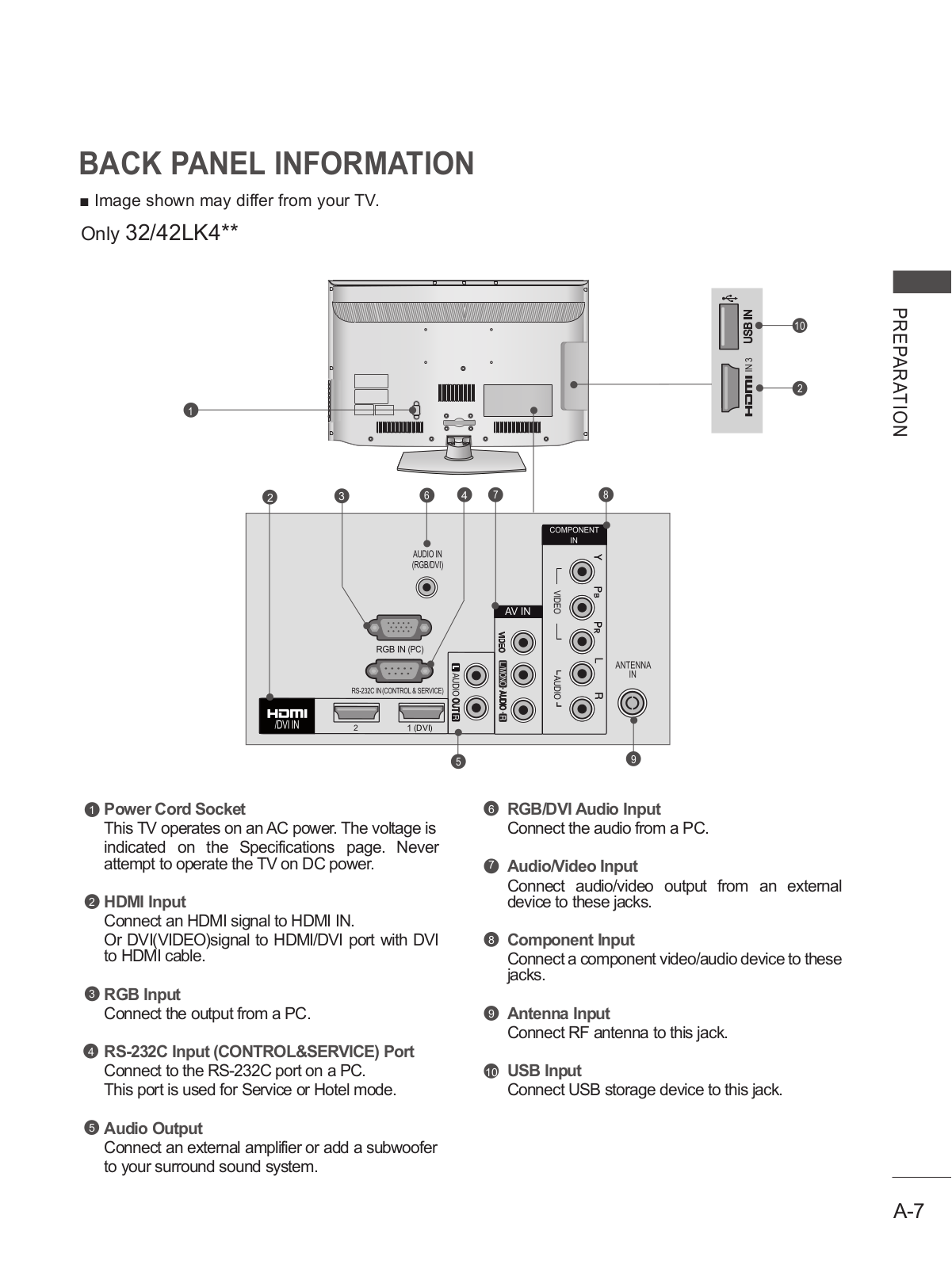
32LK4
2
32LK410
3
32LK410-TB
2
32LK410-TH
32LK43
2
32LK430
27
32LK430A
32LK430A-ZA
32LK430N
32LK430-SA
2
32LK430-TB
32LK430-UA
2
32LK430-ZA
32LK43 Series
3
32LK4 Series
Loading...
Loading...
Nothing found
32LK310Z-TA
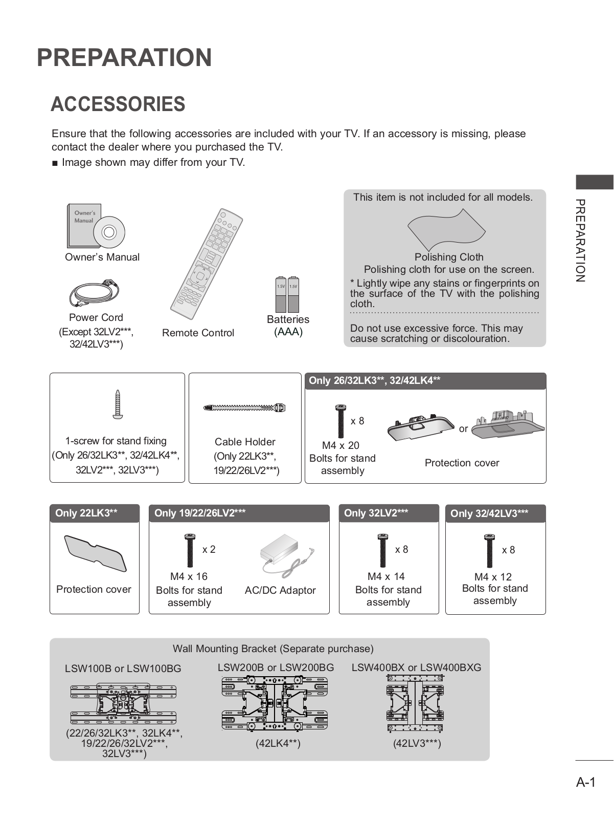
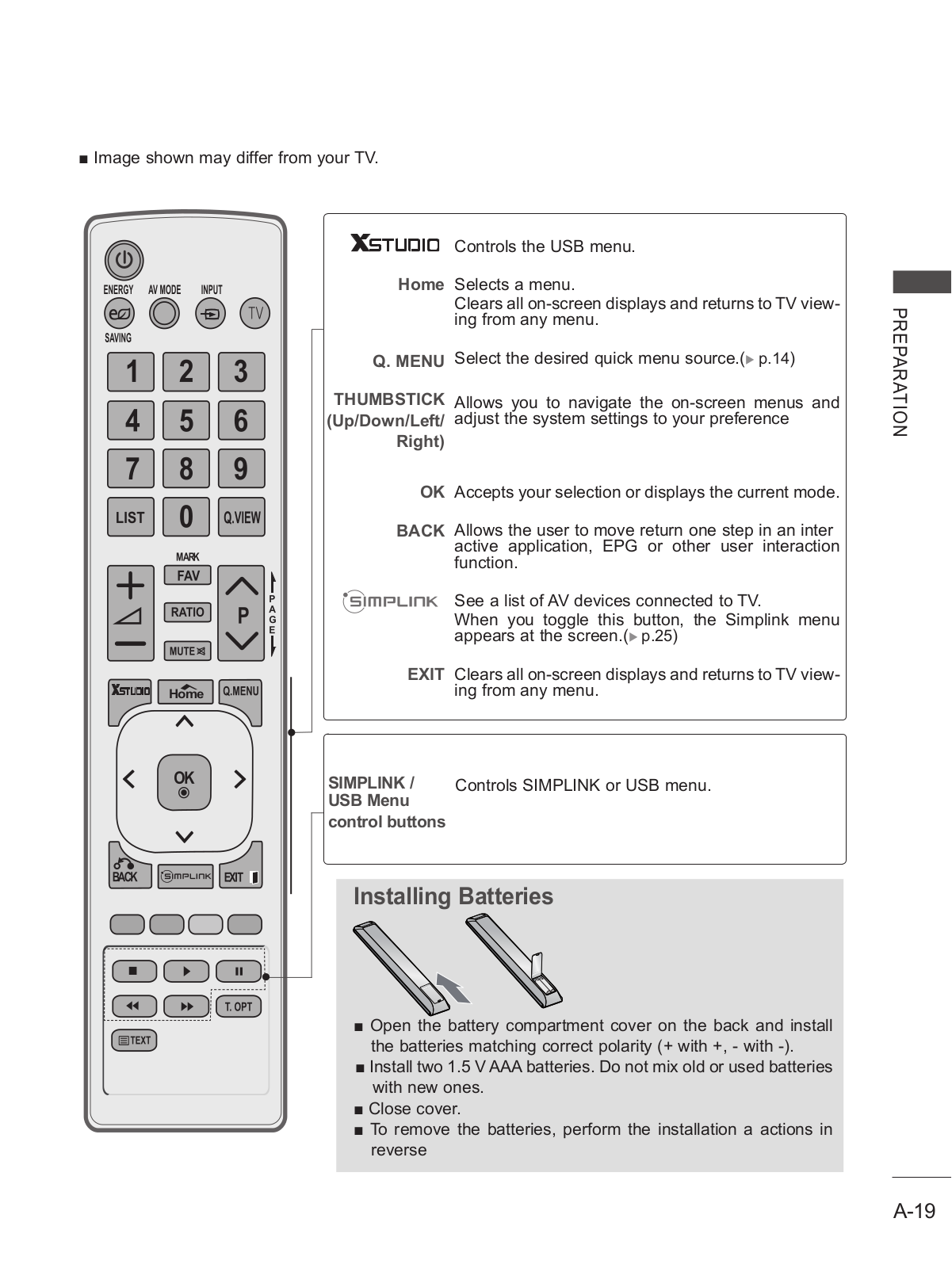
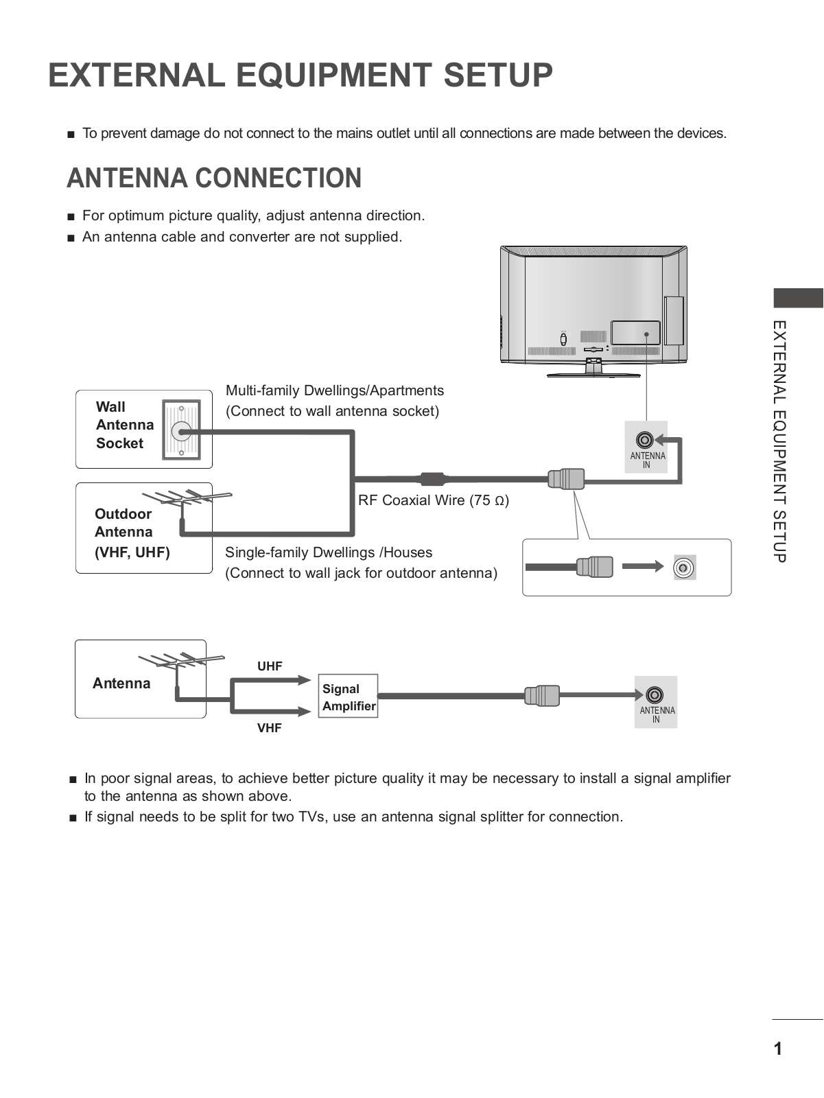
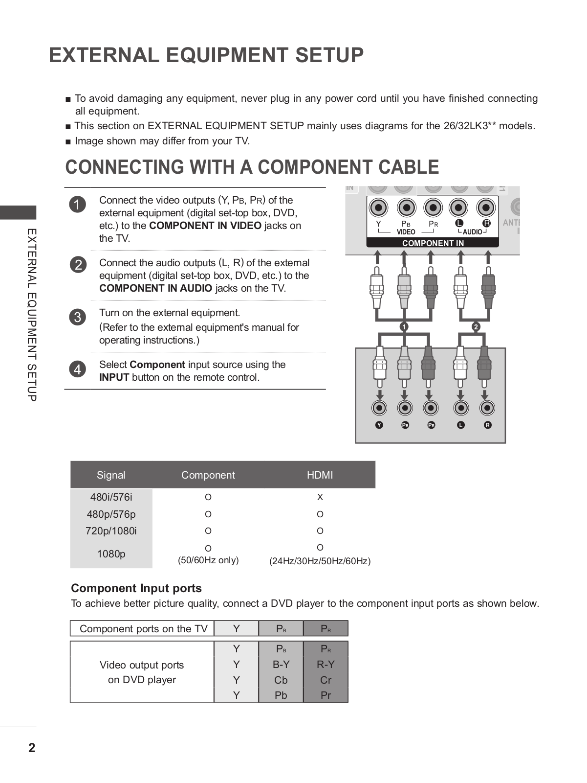
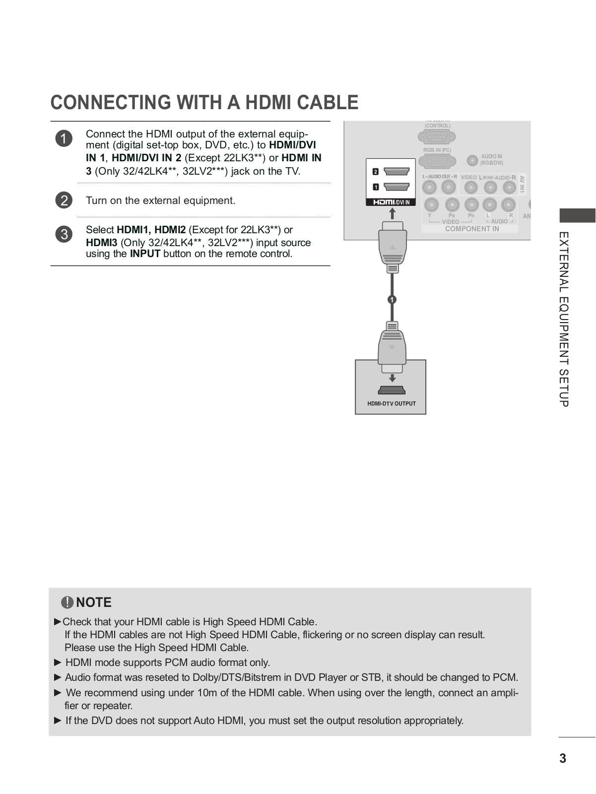
Owner’s Manual
109 pgs
25.04 Mb
0
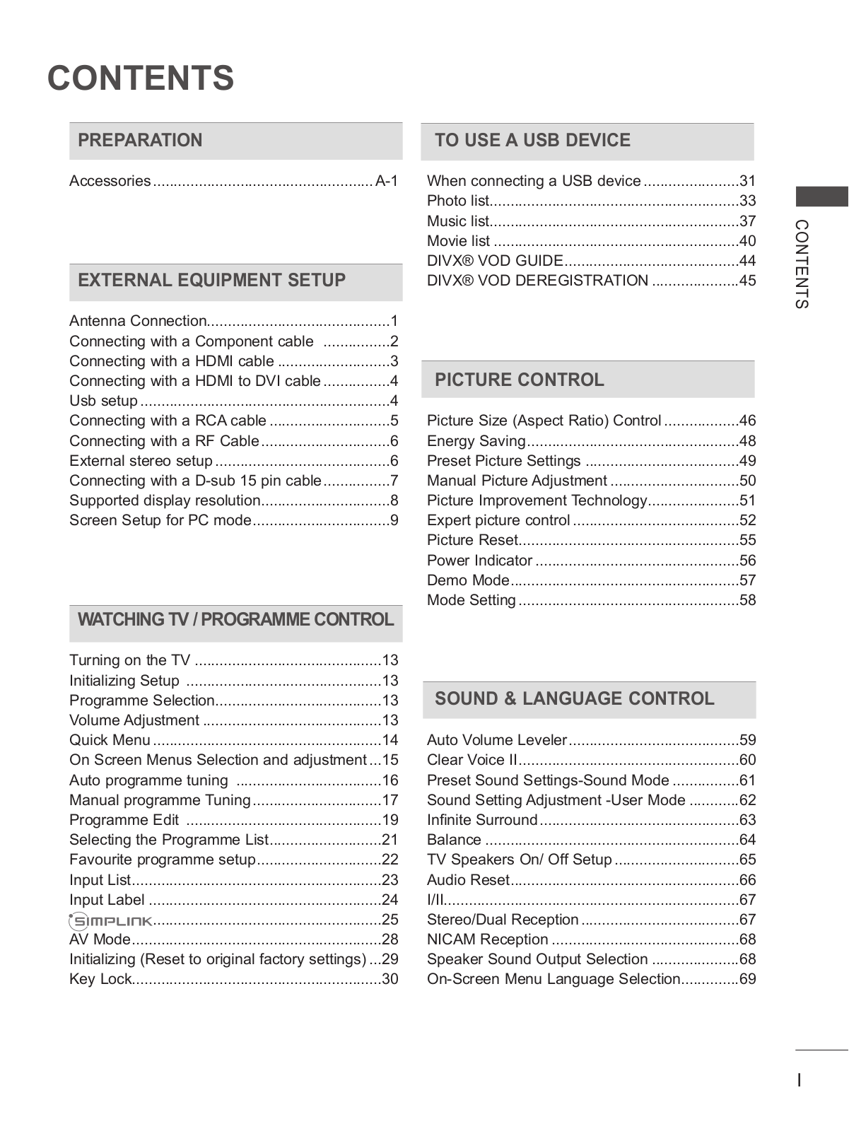
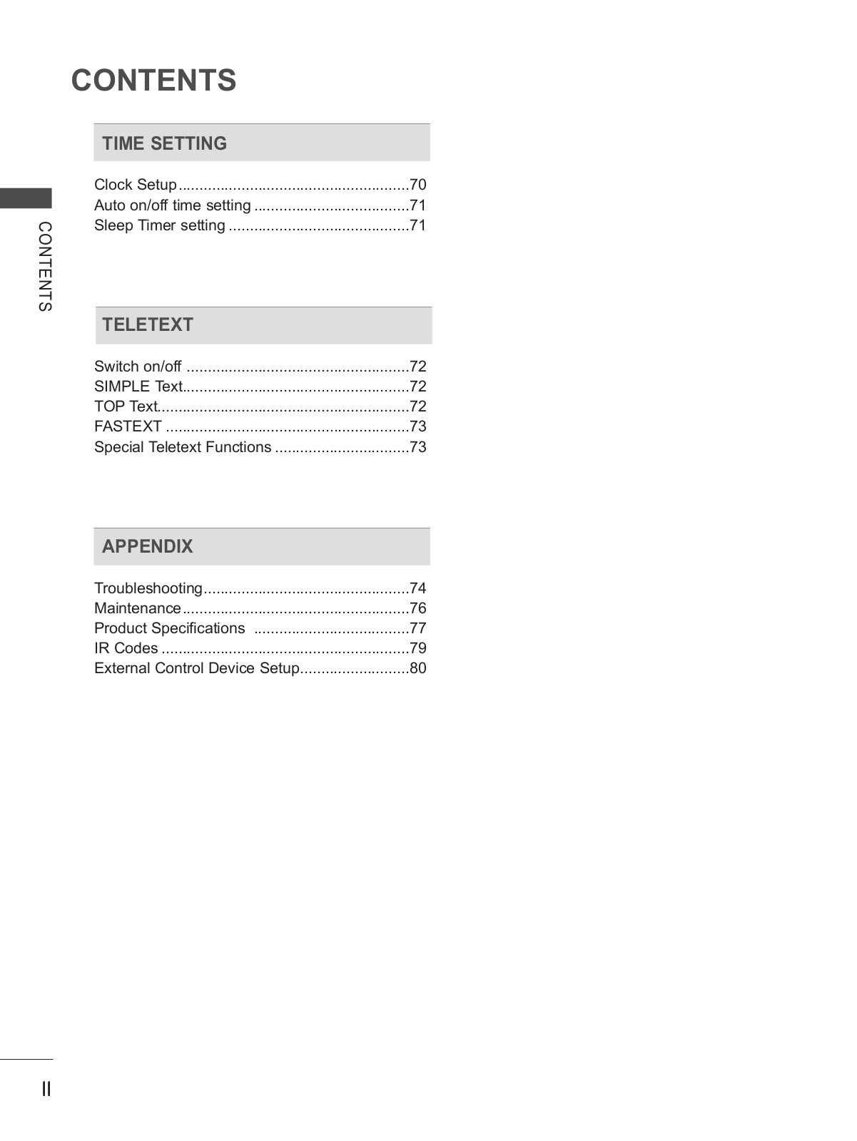
Table of contents
Loading...
LG 32LK310Z-TA Owner’s Manual
...
LG Owner’s Manual
Download
Specifications and Main Features
Frequently Asked Questions
User Manual
Download
Loading...
+
79
hidden pages
Unhide
You need points to download manuals.
1 point = 1 manual.
You can buy points or you can get point for every manual you upload.
Buy points
Upload your manuals
 Loading...