

LG 32LH30FR Owner’s Manual

OWNER’S MANUAL
LCD TV MODELS
3322LLHH33******
LCD TV
Please read this manual carefully before operating
your TV.
Retain it for future reference.
Record the model number and serial number of the
TV.
Refer to the label on the back cover and quote this
information.
To your dealer when requiring any service.
ENGLISH

HDMI, the HDMI logo and High-Definition
Multimedia Interface are trademarks or registered
trademarks of HDMI Licensing LLC.
1
ACCESSORIES
ACCESSORIES
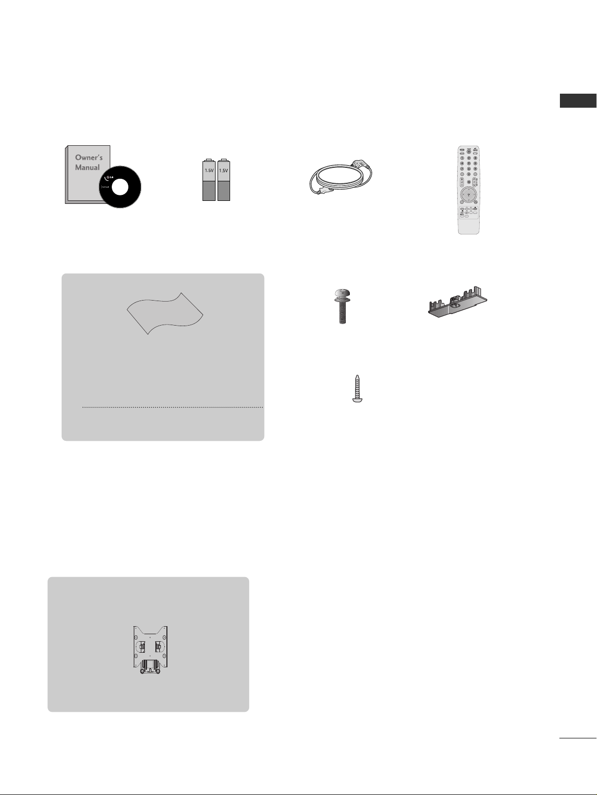
Ensure that the following accessories are included with your TV.
If an accessory is missing, please contact the dealer where you purchased the TV.
■
Image shown may differ from your TV.
Owner’s Manual
Batteries
Remote Control
Power Cord
Polishing Cloth
Polishing cloth for use on the screen.
This item is not included for all models.
* Lightly wipe any stains or fingerprints on
the surface of the TV with the polishing
cloth.
Do not use excessive force. This may cause
scratching or discolouration.
Bolts for stand assembly
(Refer to p.6)
x 4
Protection cover
(Refer to p.6)
1-screw for stand fixing
(Refer to p.6)
Wall Mounting Bracket(Separate purchase)
RW230
(32LF3***)
AV MODEV MODE
ENERGYENERGY SA SAVINGVING
RETURN
MENU
Q.MENU
MARK
MUTEMUTE
LISTLIST
Q.VIEWQ.VIEW
FAV

CONTENTS
2
CONTENTS
ACCESSORIES
. . . . . . . . . . . . . . . . . . . . . . . . . . . . . . . . . . . . . . . . . . . .
1
PREPARATION
Front Panel Controls . . . . . . . . . . . . . . . . . . . . . . . . 4
Back Panel Information . . . . . . . . . . . . . . . . . . . . . . 5
Stand Installation . . . . . . . . . . . . . . . . . . . . . . . . . . . 6
Swivel Stand . . . . . . . . . . . . . . . . . . . . . . . . . . . . . . 6
Not Using the desk-type stand . . . . . . . . . . . . . . . .6
Attaching the TV to a desk . . . . . . . . . . . . . . . . . . . .6
Back Cover for Wire Arrangement . . . . . . . . . . . . . 7
Careful Installation Advice . . . . . . . . . . . . . . . . . . . . 7
Desktop Pedestal Installation . . . . . . . . . . . . . . . . . 8
Wall Mount: Horizontal Installation . . . . . . . . . . . . 8
KENSINGTON SECURITY SYSTEM
. . . . . . . . . . . . . . . . . . 9
Antenna Connection . . . . . . . . . . . . . . . . . . . . . . . 10
EXTERNAL EQUIPMENT SETUP
HD Receiver Setup . . . . . . . . . . . . . . . . . . . . . . . . . 11
DVD Setup . . . . . . . . . . . . . . . . . . . . . . . . . . . . . . . .13
VCR Setup . . . . . . . . . . . . . . . . . . . . . . . . . . . . . . . 15
Other A/V Source Setup . . . . . . . . . . . . . . . . . . . . 17
External Stereo Setup . . . . . . . . . . . . . . . . . . . . . . 18
AV Output Setup . . . . . . . . . . . . . . . . . . . . . . . . . . 18
Usb in Setup . . . . . . . . . . . . . . . . . . . . . . . . . . . . . .19
PC Setup . . . . . . . . . . . . . . . . . . . . . . . . . . . . . . . . 20
- Screen Setup for PC Mode . . . . . . . . . . . . . . 22
WATCHING TV / PROGRAMME CONTROL
Remote Control Key Functions . . . . . . . . . . . . . . . 26
Turning on the TV . . . . . . . . . . . . . . . . . . . . . . . . . 28
Programme Selection . . . . . . . . . . . . . . . . . . . . . . 28
Volume Adjustment . . . . . . . . . . . . . . . . . . . . . . . 28
Quick Menu . . . . . . . . . . . . . . . . . . . . . . . . . . . . . 29
On-Screen Menus Selection and Adjustment . . . 30
Auto Programme Tuning . . . . . . . . . . . . . . . . . . . . 31
Manual Programme Tuning . . . . . . . . . . . . . . . . . . 32
Programme Edit . . . . . . . . . . . . . . . . . . . . . . . . . . . 34
Selecting the Programme List . . . . . . . . . . . . . . . . 36
Favourite Programme Setup . . . . . . . . . . . . . . . . . 37
Input List . . . . . . . . . . . . . . . . . . . . . . . . . . . . . . . . 38
Input Label . . . . . . . . . . . . . . . . . . . . . . . . . . . . . . . 39
. . . . . . . . . . . . . . . . . . . . . . . . . . . . . 40
Key Lock . . . . . . . . . . . . . . . . . . . . . . . . . . . . . . . . . 43
Initializing(Reset to original factory settings) . . . 44
AV Mode . . . . . . . . . . . . . . . . . . . . . . . . . . . . . . . . 45
TO USE A USB DEVICE
When connecting the USB device . . . . . . . . . . . . 46
Photo List . . . . . . . . . . . . . . . . . . . . . . . . . . . . . . . . 47
Music List . . . . . . . . . . . . . . . . . . . . . . . . . . . . . . . .51
Movie List . . . . . . . . . . . . . . . . . . . . . . . . . . . . . . . .54
Divx Registration Code . . . . . . . . . . . . . . . . . . . . . .57
Deactivation . . . . . . . . . . . . . . . . . . . . . . . . . . . . . .58

CONTENTS
3
PICTURE CONTROL
Picture Size (Aspect Ratio) Control....................... 59
Energy Saving............................................................... 61
Preset Picture Settings
- Picture Mode-Preset............................................ 62
Manual Picture Adjustment
- Picture Mode-User option................................. 63
Picture Improvement Technology ........................... 64
Expert Picture Control............................................... 65
Picture Reset................................................................. 68
Power Indicator .............................................................69
Demo Mode.................................................................. 70
Mode Setting................................................................ 71
SOUND & LANGUAGE CONTROL
Auto Volume Leveler................................................... 72
Preset Sound Settings - Sound Mode................... 73
Sound Setting Adjustment - User Mode .............. 74
SRS TruSurround XT .................................................. 74
Clear Voice ll................................................................. 75
Balance........................................................................... 76
TV Speakers On/ Off Setup..................................... 77
Selecting Audio Out................................................... 78
Audio Reset....................................................................79
I/II
- Stereo/Dual Reception....................................... 80
- NICAM Reception .............................................................. 81
- Speaker Sound Output Selection .....................81
On-Screen Menu Language Selection......................... 82
TIME SETTING
Clock Setup .................................................................. 83
Auto On/ Off Timer Setting..................................... 84
Sleep Timer Setting .................................................... 84
TELETEXT
Switch on/off ............................................................... 85
SIMPLE Text.................................................................. 85
TOP Text........................................................................ 85
FASTEXT.........................................................................86
Special Teletext Functions ........................................ 86
APPENDIX
Troubleshooting........................................................... 87
Maintenance ................................................................ 89
Product Specifications............................................... 90
IR Codes ........................................................................ 91
External Control Device Setup................................ 93
PREPARATION
4
PREPARATION
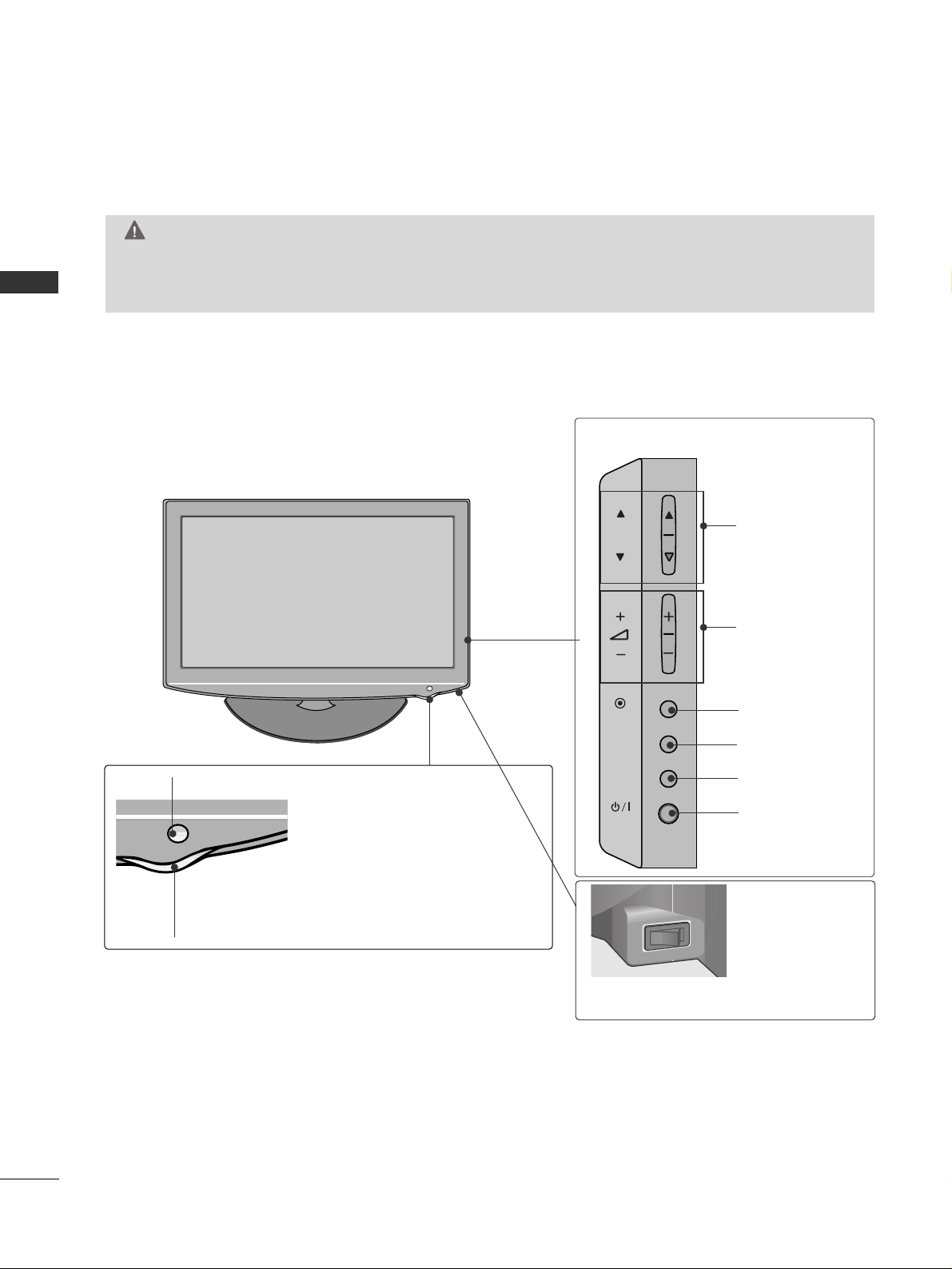
FRONT PANEL CONTROLS
■
Image shown may differ from your TV.
GG
When the TV cannot be turned on with the remote control, press the main power button on the TV.
(When the power is turned off with the main power button on the TV, it will not be turned on with the
remote control.)
CAUTION
PROGRAMME
VOLUME
OK
MENU
INPUT
POWER
Remote Control Sensor
Power/Standby Indicator
• Illuminates red in standby mode.
•
Illuminates blue when the TV is switched on.
ON OFF
Main Power Switch
P
OK
MENU
INPUT
5
PREPARATION
P
AUDIO
VIDEO
L(L(MONO)MONO)
R
AUDIOAUDIO
AV
VIDEOVIDEO
IN1
OUT
VARIABLE AUDIO OUTVARIABLE AUDIO OUT
ANTENNA
IN
RGB IN
(PC)
RS-232C IN
(CONTROL)
AUDIO IN
(RGB/DVI)
1
2
/DVI IN
COMPONENT IN
5
3
2
4
6
8
9
7
AV IN2
IN 3
2
7
10
1
■
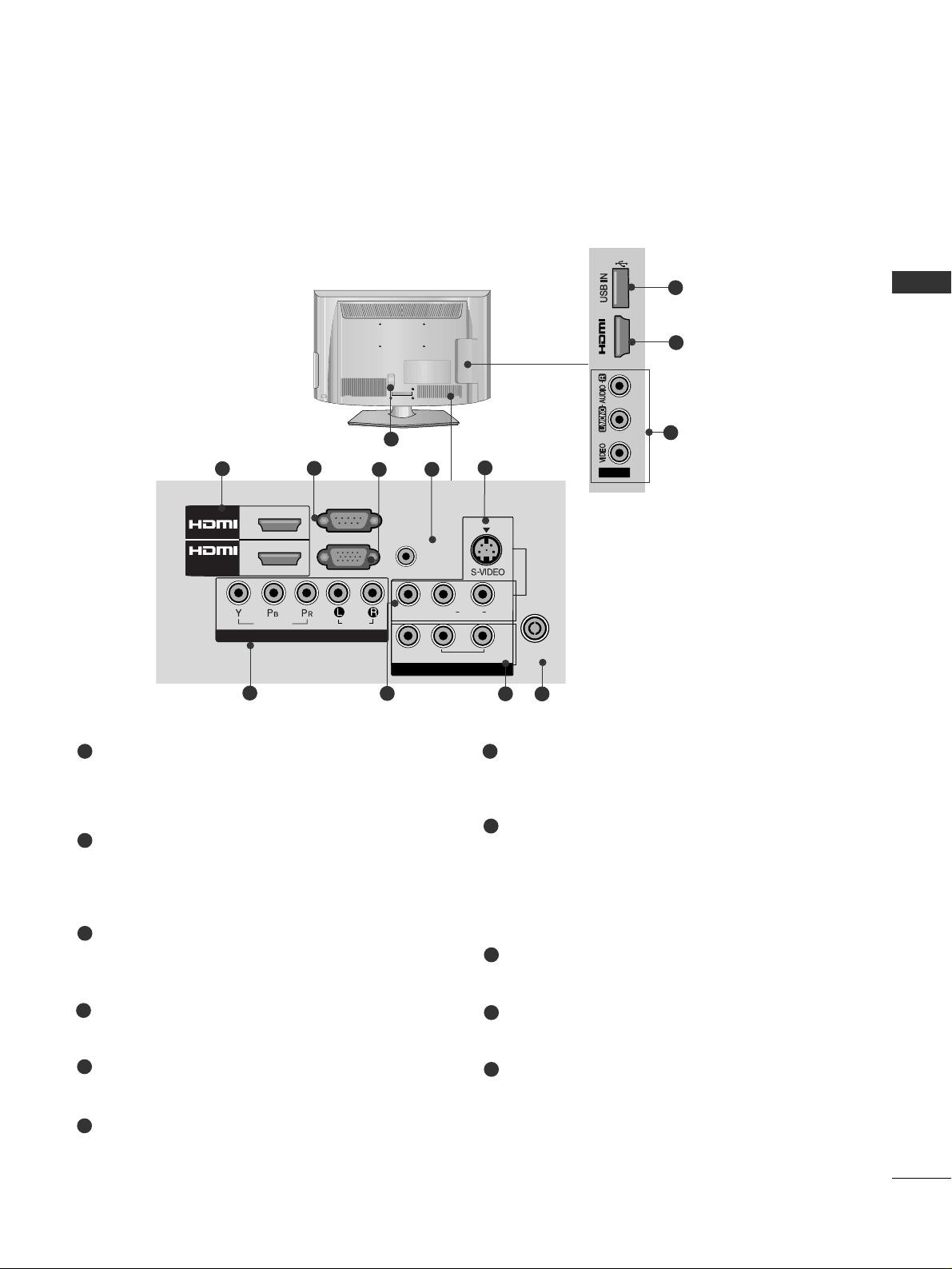
Image shown may differ from your TV.
Power Cord Socket
This TV operates on an AC power. The voltage is
indicated on the Specifications page. Never
attempt to operate the TV on DC power.
HDMI Input
Connect a HDMI signal to HDMI IN.
Or DVI(VIDEO)signal to HDMI/DVI port with DVI
to HDMI cable.
RS-232C IN PORT
Connect to the RS-232C port on a PC.
This port is used for Service or Hotel mode.
RGB IN Input
Connect the output from a PC.
RGB/DVI Audio Input
Connect the audio from a PC.
Component Input
Connect a component video/audio device to
these jacks.
Audio/Video Input
Connect audio/video output from an external
device to these jacks.
AV Output
Connect second TV or monitor to the AV OUT
socket on the TV.
Variable Audio Output
Connect an external amplifier or add a subwoofer
to your surround sound system.
Antenna Input
Connect RF antenna to this jack.
USB IN Input
Connect USB storage device to this jack.
S-Video Input
Connect S-Video out from an S-VIDEO device.
1
2
3
4
5
6
8
9
10
11
7
11
BACK PANEL INFORMATION
6
PREPARATION
PREPARATION
STAND INSTALLATION
■
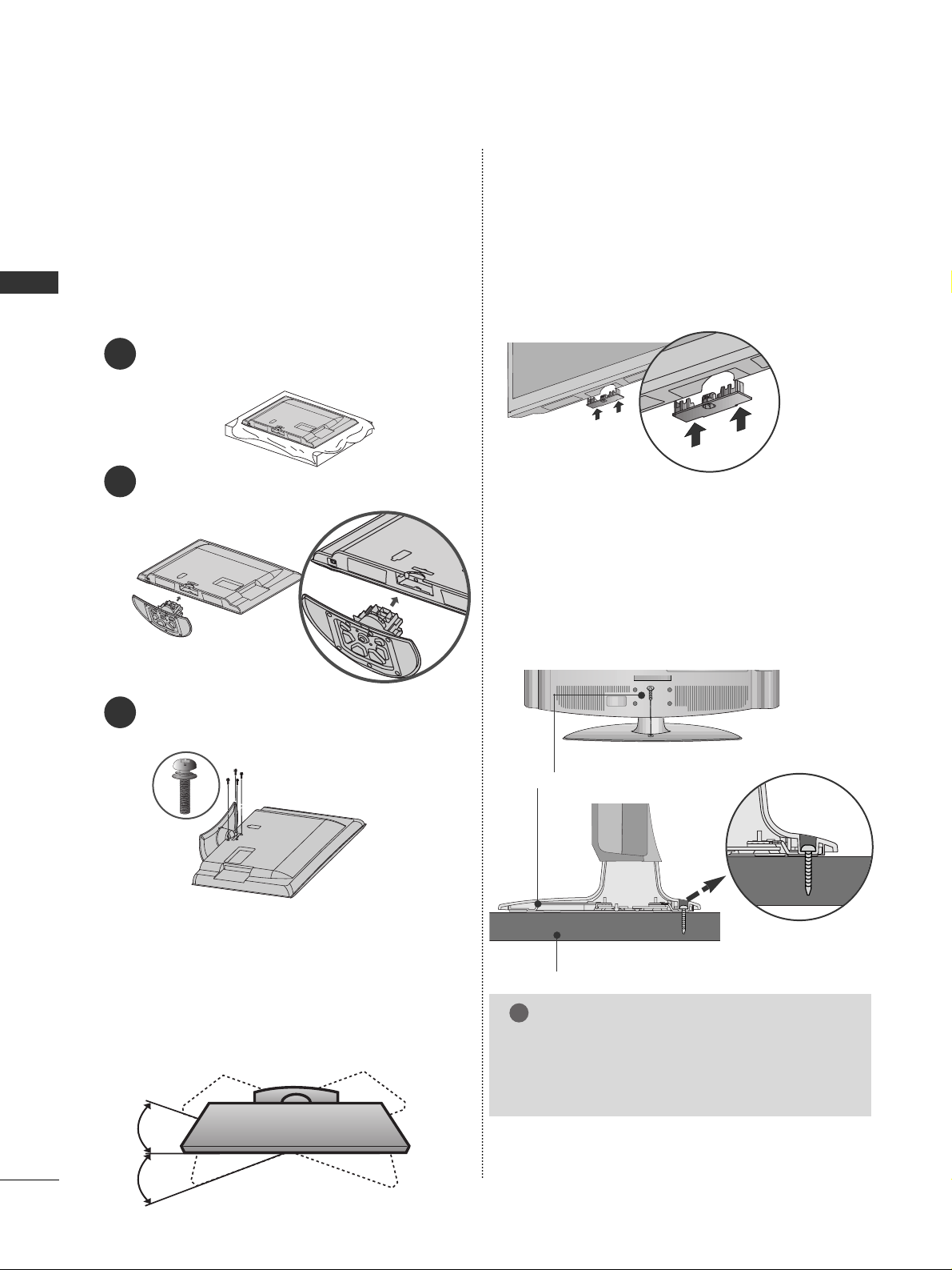
Image shown may differ from your TV.
When assembling the desk type stand, check whether the
bolt is fully tightened. (If not tightened fully, the product
can tilt forward after the product installation.) If you
tighten the bolt with excessive force, the bolt can deviate
from abrasion of the tightening part of the bolt.
1
2
3
Carefully place the TV screen side down on a cushioned
surface to protect the screen from damage.
Assemble the TV as shown.
Fix the 4 bolts securely using the holes in the
back of the TV.
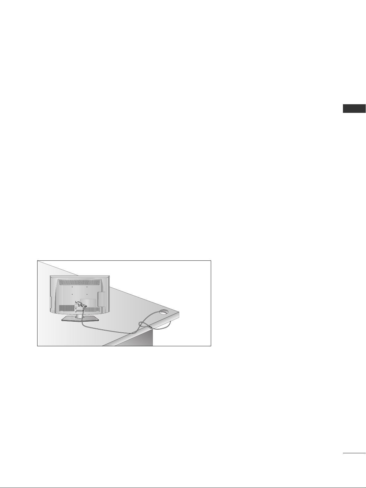
ATTACHING THE TV TO A DESK
■
Image shown may differ from your TV.
The TV must be attached to desk so it cannot be pulled
in a forward/backward direction, potentially causing
injury or damaging the product. Use only an attached
screw.
1-Screw (provided as parts of the product)
Desk
Stand
WARNING
!
G
To prevent TV from falling over, the TV should
be securely attached to the floor/wall per installation instructions. Tipping, shaking, or rocking the
machine may cause injury.
■
Image shown may differ from your TV.
When installing the wall-mounted unit, use the protection cover.
NOT USING THE DESK-TYPE STAND
Insert the
PPRROOTTEECCTTIIOONN CCOOVVEERR
into the TV
until clicking sound.
SWIVEL STAND
■
This feature is not available for all models.
■
After installing the TV, you can adjust the TV manually
to the left or right direction by 20 degrees to suit your
viewing position.
7
PREPARATION
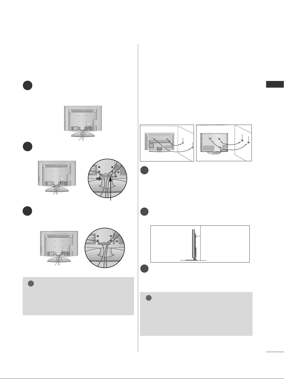
BACK COVER FOR WIRE ARRANGEMENT
■
Image shown may differ from your TV.
Connect the cables as necessary.
To connect additional equipment, see the
External Equipment Setup section of the manual.
1
Open the
CC AA BBLLEE MMAANNAAGGEEMMEENN TT CCLLIIPP
as
shown and manage the cables.
2
CABLE MANAGEMENT CLIP
Fit the
CC AA BBLLEE MMAANNAAGGEEMMEENN TT CCLLIIPP
as
shown.
3
GG
Do not hold the CABLE MANAGEMENT CLIP
when moving the TV.
- If the TV is dropped, you may be injured or
the TV may be damaged.
NOTE
!
CAREFUL INSTALLATION ADVICE
A
You should purchase necessary components to fix the TV
safety and secure to the wall on the market.
A
Position the TV close to the wall to avoid the possibility
of it falling when pushed.
A
The instructions shown below are a safer way to set up
the TV, by fixing it to the wall, avoiding the possibility of
it falling forwards if pulled. This will prevent the TV from
falling forward and causing injury. This will also prevent
the TV from damage. Ensure that children do not climb
or hang from the TV.
NOTE
!
G
When moving the TV undo the cords first.
G
Use a platform or cabinet strong and large enough
to support the size and weight of the TV.
G
To use the TV safely make sure that the height of the
bracket on the wall and on the TV is the same.
3
1
2
Use the eye-bolts or TV brackets/bolts to fix the
product to the wall as shown in the picture.
(If your TV has bolts in the eyebolts, loosen then
bolts.)
* Insert the eye-bolts or TV brackets/bolts and tight-
en them securely in the upper holes.
Secure the wall brackets with the bolts on the wall.
Match the height of the bracket that is mounted on
the wall.
3
Use a sturdy rope to tie the product for alignment. It
is safer to tie the rope so it becomes horizontal
between the wall and the product.
2
1
2
1
8
PREPARATION
PREPARATION
A
The TV can be installed in various ways such as on
a wall, or on a desktop etc.
A
The TV is designed to be mounted horizontally.
Power Supply
Circuit breaker
EARTHING
Ensure that you connect the earth wire to prevent
possible electric shock. If grounding methods are not
possible, have a qualified electrician install a separate
circuit breaker.
Do not try to earth the TV by connecting it to telephone wires, lightening rods or gas pipes.
4 inches
4 inches
4 inches
4 inches
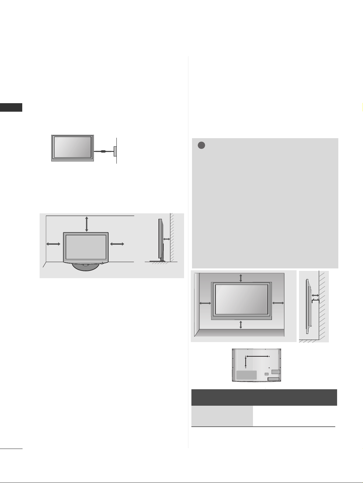
DESKTOP PEDESTAL INSTALLATION
For adequate ventilation allow a clearance of 4”
(10cm) all around the TV.
WALL MOUNT: HORIZONTAL INSTALLATION
A
We recommend the use of a LG Brand wall mounting
bracket when mounting the TV to a wall.
A
We recommend that you purchase a wall mounting
bracket which supports VESA standard.
A
LG recommends that wall mounting be performed
by a qualified professional installer.
4 inches
4 inches
4 inches
4 inches
4 inches
NOTE
!
G Should Install wall mount on a solid wall perpendicular to
the floor.
G Should use a special wall mount, if you want to install it to
ceiling or slanted wall.
G The surface that wall mount is to be mounted on should
be of sufficient strength to support the weight of TV set;
e.g. concrete, natural rock, brick and hollow block.
G Installing screw type and length depends on the wall
mount used. Further information, refer to the instructions
included with the mount.
G LG is not liable for any accidents or damage to property or
TV due to incorrect installation:
- Where a non-compliant VESA wall mount is used.
- Incorrect fastening of screws to surface which may cause
TV to fall and cause personal injury.
- Not following the recommended Installation method.
Model
VESA
(A *B)
Standard
Screw
Quantity
32LH3***
200 * 10 0 M 4 4
AA
BB
9
PREPARATION
KENSINGTON SECURITY SYSTEM
■
This feature is not available for all models.
■
Image shown may differ from your TV.
The TV is equipped with a Kensington Security System connector on the back panel. Connect the Kensington
Security System cable as shown below.
For the detailed installation and use of the Kensington Security System, refer to the user’s guide provided with
the Kensington Security System.
For further information, contact http://www.kensington.com, the internet homepage of the Kensington
company. Kensington sells security systems for expensive electronic equipment such as notebook PCs and LCD
projectors.
NOTE
- The Kensington Security System is an optional accessory.
NOTES
a. If the TV feels cold to the touch, there may be a small “flicker” when when it is turned on.
This is normal, there is nothing wrong with TV.
b. Some minute dot defects may be visible on the screen, appearing as tiny red, green, or blue spots. However,
they have no adverse effect on the monitor's performance.
c. Avoid touching the LCD screen or holding your finger(s)
against it for long periods of time.
Doing so may produce some temporary distortion effects on the screen.
10
PREPARATION
PREPARATION
P
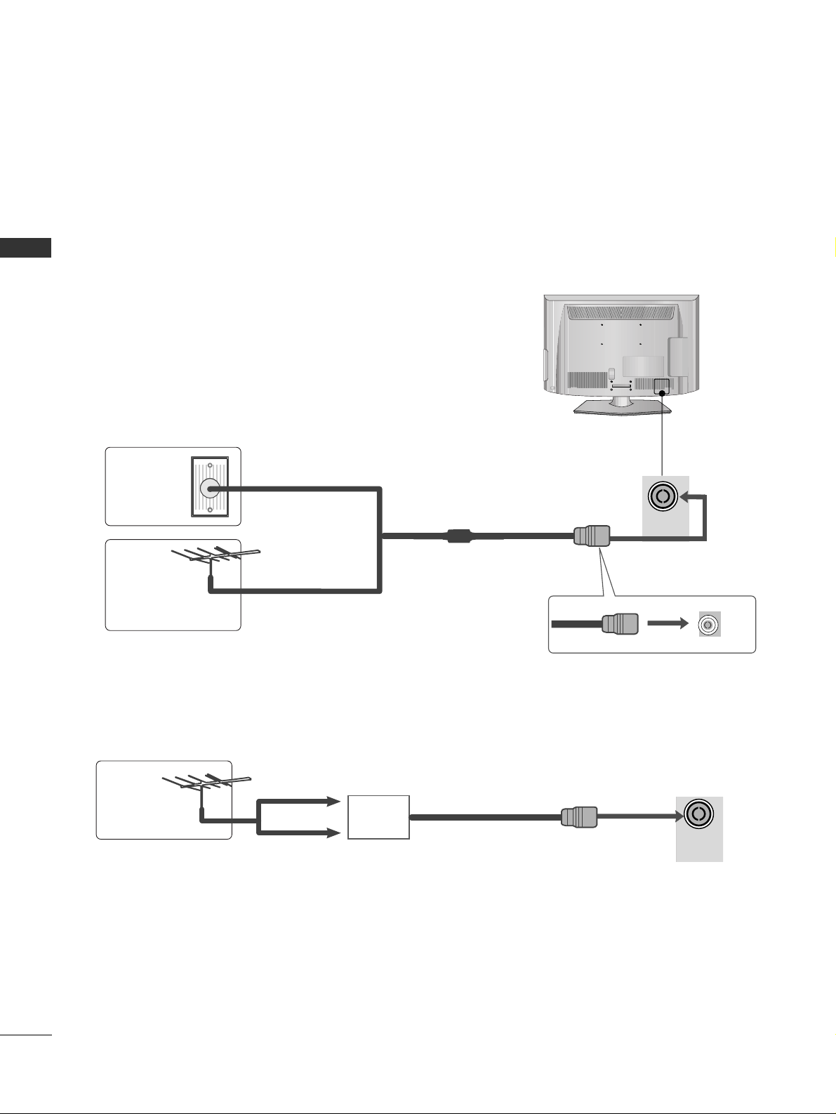
ANTENNA CONNECTION
■
For optimum picture quality, adjust antenna direction.
■
An antenna cable and converter are not supplied.
■
To prevent damage do not connect to the mains outlet until all connections are made between the devices.
Multi-family Dwellings/Apartments
(Connect to wall antenna socket)
Single-family Dwellings /Houses
(Connect to wall jack for outdoor antenna)
Outdoor
Antenna
(VHF, UHF)
Wall
Antenna
Socket
RF Coaxial Wire (75 ohm)
Antenna
UHF
Signal
Amplifier
VHF
■
In poor signal areas, to achieve better picture quality it may be necessary to install a signal amplifier to the
antenna as shown above.
■
If signal needs to be split for two TVs, use an antenna signal splitter for connection.
ANTENNA
IN
ANTENNA
IN
11
EXTERNAL EQUIPMENT SETUP
EXTERNAL EQUIPMENT SETUP
COMPONENT IN
AUDIO
VIDEO
HD RECEIVER SETUP
■
To avoid damaging any equipment, never plug in any power cords until you have finished connecting all equipment.
■
Image shown may differ from your TV.
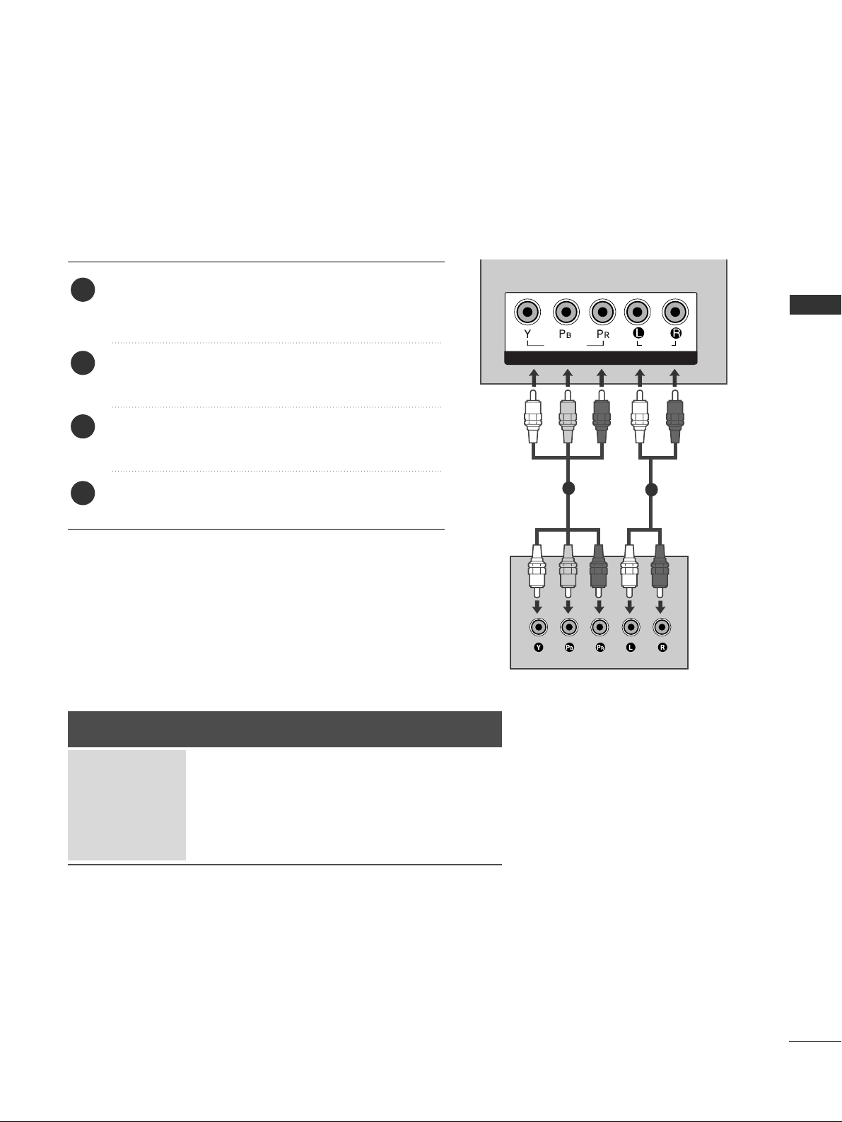
Connecting with a component cable
1
2
Signal
480i/576i
480p/576p
720p/1080i
1080p
Component
O
O
O
O
(50/60Hz only)
HDMI
X
O
O
O
(24Hz/30Hz/50Hz/60Hz)
Connect the video outputs (Y, PB, P
R
)
of the digital set
top box to the
CC OOMMPPOO NNEENN TT IINN VVII DDEEOO
jacks on the
TV.
Connect the audio output of the digital set-top box to
the
CC OOMMPPOO NNEENN TT IINN AAUUDD II OO
jacks on the TV.
Turn on the digital set-top box.
(
Refer to the owner’s manual for the digital set-top box.
)
Select
CC oomm ppoonnee nn tt
input source using the
IINNPP UUTT
button on the remote control.
2
3
4
1
12
EXTERNAL EQUIPMENT SETUP
EXTERNAL EQUIPMENT SETUP
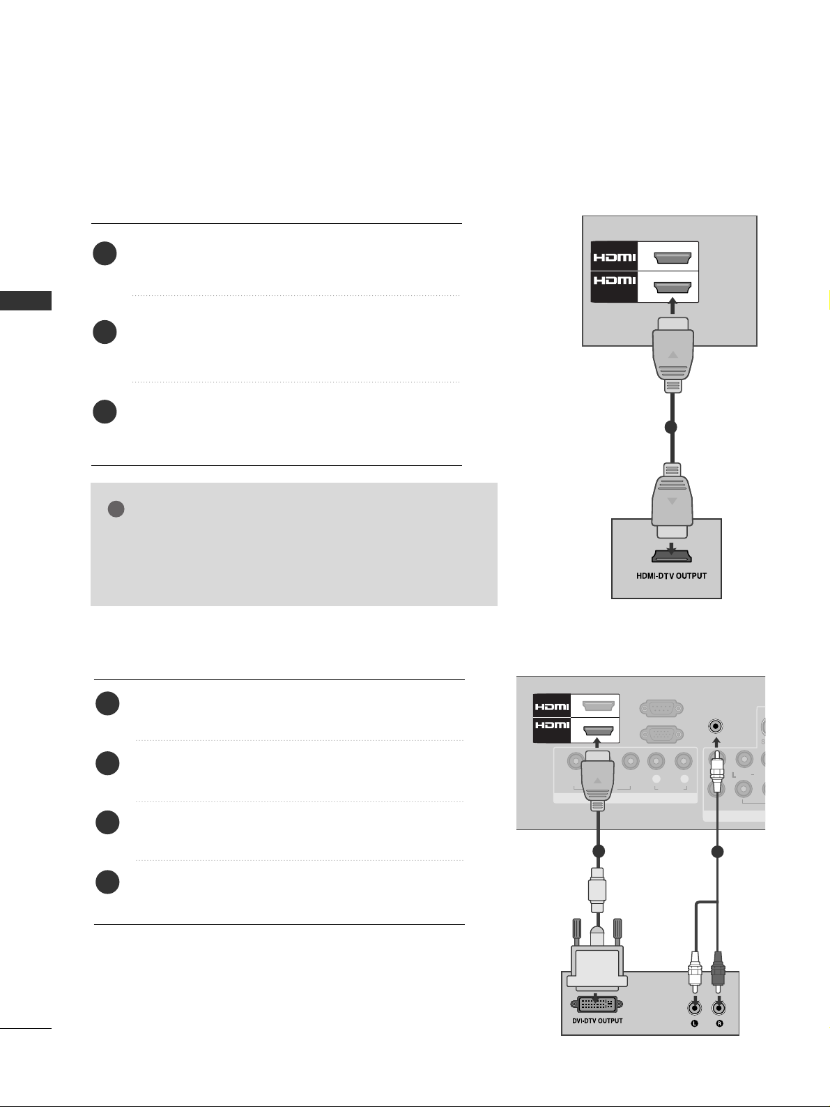
Connecting a set-top box with an HDMI cable
Connect the digital set-top box to
HHDDMMII// DDVV II IINN 11
,
HHDDMMII II NN22 orHHDDMMII II NN33
jack on the TV.
Turn on the digital set-top box.
(
Refer to the owner’s manual for the digital set-top box.
)
Select
HHDDMMII11. HHDDMMII22 orHHDDMMII II NN33
input source
using the
IINNPP UUTT
button on the remote control.
2
3
1
GG
Check that your HDMI cable is version 1.3 or higher.
If the HDMI cables don’t support HDMI version 1.3, flickering or no screen display can result. Please use the latest
cables that support at least HDMI version 1.3.
NOTE
!
1
2
/DVI IN
1
Connecting with an HDMI to DVI cable
Connect the digital set-top box to
HHDDMMII// DDVV II IINN 11
jack on the TV.
Connect the audio output of the digital set-top box to
the
AA UUDDIIOO IINN (( RRGGBB // DDVV II ))
jack on the TV.
Turn on the digital set-top box. (Refer to the owner’s
manual for the digital set-top box.
)
Select
HHDDMMII11
input source using the
IINNPPUUTT
button
on the remote control.
2
3
4
1
COMPONENT IN
VIDEO
LYP
BPR
R
AUDIO
VIDEO
AUD
/MONO
RGB IN
(PC)
RS-232C IN
(CONTROL)
AUDIO IN
(RGB/DVI)
AV
VARIABLE AUDIO
1
/DVI IN
2
1
2
13
EXTERNAL EQUIPMENT SETUP
DVD SETUP
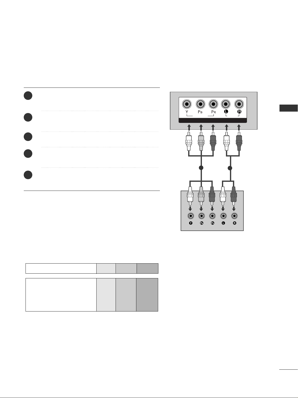
Connecting with a component cable
COMPONENT IN
AUDIO
VIDEO
Component Input ports
To achieve better picture quality, connect a DVD player to the component input ports as shown below.
Component ports on the TV
YPB PR
Video output ports
on DVD player
Y
Y
Y
Y
P
B
B-Y
Cb
Pb
PR
R-Y
Cr
Pr
1
2
Connect the video outputs (Y, P
B, PR
)
of the DVD to the
CC OOMMPPOO NNEENN TT IINN VVIIDDEEOO
jacks on the TV.
Connect the audio outputs of the DVD to the
CC OOMMPPOO NNEENN TT IINN AAUUDD II OO
jacks on the TV.
Turn on the DVD player, insert a DVD.
Select
CC oommppoonneenn tt
input source using the
IINNPPUUTT
button on the remote control.
Refer to the DVD player's manual for operating instructions.
2
3
4
5
1
14
EXTERNAL EQUIPMENT SETUP
EXTERNAL EQUIPMENT SETUP
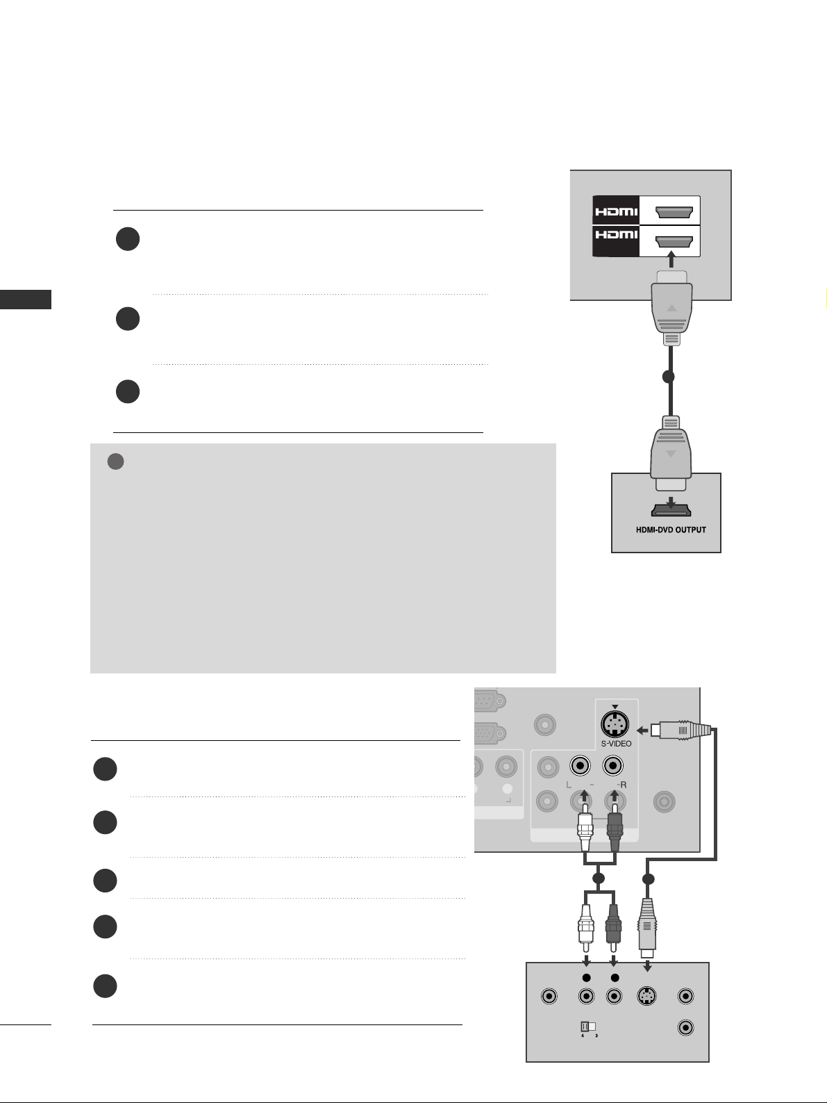
GG
The TV can receive video and audio signals simultaneously when using a
HDMI cable.
GG
If the DVD does not support Auto HDMI, you must set the output resolution appropriately.
GG
Check that your HDMI cable is version 1.3 or higher.
If the HDMI cables don’t support HDMI version 1.3, flickering or no
screen display can result. Please use the latest cables that support at
least HDMI version 1.3.
GG
We recommed using under 10m of the HDMI cable. When using over the
length, connect a amplifier or repeater.
NOTE
!
Connecting the HDMI cable
Connect the HDMI output of the DVD to the
HHDDMMII// DDVV II IINN 11,HHDDMMII II NN22 orHHDDMMII II NN33
jack on
the TV.
Select
HHDDMMII11, HHDDMMII II NN22 orHHDDMMII II NN33
input
source using the
IINNPP UUTT
button on the remote control.
Refer to the DVD player's manual for operating instructions.
2
3
1
1
2
/DVI IN
1
Connecting with a S-Video cable
Connect the S-VIDEO output of the DVD to the
SS --VV IIDD EEOO
input on the TV.
Connect the audio outputs of the DVD to the
AA UU DDII OO
input jacks on the TV.
Turn on the DVD player, insert a DVD.
Select
AA VV 11
input source using the
IINNPPUUTT
button
on the remote control.
Refer to the DVD player's manual for operating
instructions.
2
3
4
5
1
AUDIO
VIDEO
AUDIO
/MONO
ANTENNA
IN
(PC)
O)
AUDIO IN
(RGB/DVI)
AV
VARIABLE AUDIO OUT
IN1
OUT
VIDEO
OUTPUT
SWITCH
ANT IN
ANT OUT
L R
S-VIDEO
1
2
15
EXTERNAL EQUIPMENT SETUP
VCR SETUP
■
To avoid picture noise (interference), allow adequate distance between the VCR and TV.
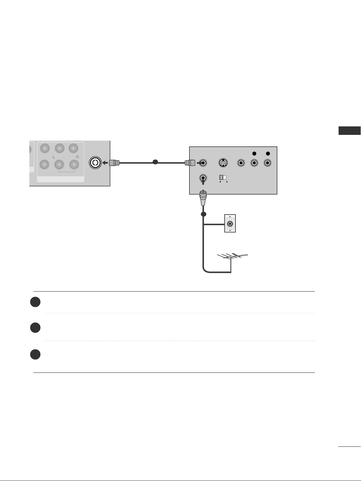
Connecting with a RF Cable
Connect the
AA NNTT OO UU TT
socket of the VCR to the
AA NNTTEE NNNN AA II NN
socket on the TV.
Connect the antenna cable to the
AA NNTT II NN
socket of the VCR.
Press the
PP LLAA YY
button on the VCR and match the appropriate channel between the TV and VCR for
viewing.
2
3
1
ANTENNA
IN
OUTPUT
SWITCH
ANT IN
R
S-VIDEO VIDEO
ANT OUT
L
VIDEO
AUDIO
/MONO
AV
VARIABLE AUDIO OUT
IN1
OUT
Wall Jack
Antenna
1
2
16
EXTERNAL EQUIPMENT SETUP
EXTERNAL EQUIPMENT SETUP
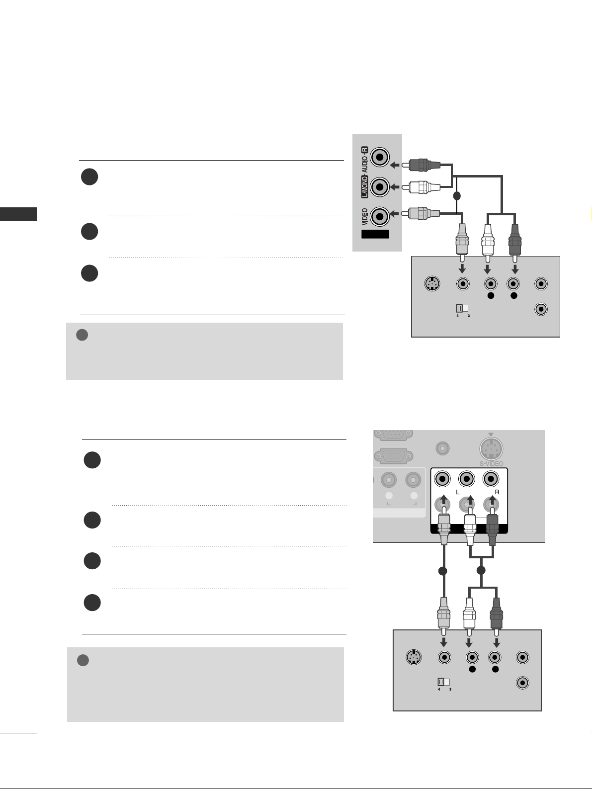
Connecting with a RCA cable
Connect the
AA UU DD II OO/VVIIDDEE OO
jacks between TV and
VCR. Match the jack colours (Video = yellow, Audio Left
= white, and Audio Right = red)
Insert a video tape into the VCR and press PLAY on
the VCR. (Refer to the VCR owner’s manual.
)
Select
AA VV 22
input source using the
IINNPP UUTT
button on
the remote control.
If connected to
AA VV IINN 11
, select
AA VV11
input source.
1
2
3
GG
If you have a mono VCR, connect the audio cable from the
VCR to the
AA UU DDIIOO LL//MMOONNOO
jack of the TV.
NOTE
!
AV IN2
L
R
S-VIDEO
VIDEO
OUTPUT
SWITCH
ANT IN
ANT OUT
GG
If both S-VIDEO and VIDEO sockets have been connected to
the S-VHS VCR simultaneously, only the S-VIDEO can be
received.
NOTE
!
L R
AUDIO
VIDEO
AUDIO
/MONO
RGB IN
(PC)
AUDIO IN
(RGB/DVI)
AV
VARIABLE AUDIO OUT
OUT
IN1
L
R
S-VIDEO
VIDEO
OUTPUT
SWITCH
ANT IN
ANT OUT
Connecting with a S-Video cable
Connect the S-VIDEO output of the VCR to the
SS --
VVIIDD EEOO
input on the TV set. The picture quality is
improved; compared to normal composite (RCA cable)
input.
Connect the audio outputs of the VCR to the
AA UU DDII OO
input jacks on the TV.
Insert a video tape into the VCR and press PLAY on the
VCR. (Refer to the VCR owner’s manual.)
Select
AA VV 11
input source with using the
IINNPPUUTT
button
on the remote control.
2
3
4
1
1
2
1
EXTERNAL EQUIPMENT SETUP
17
EXTERNAL EQUIPMENT SETUP
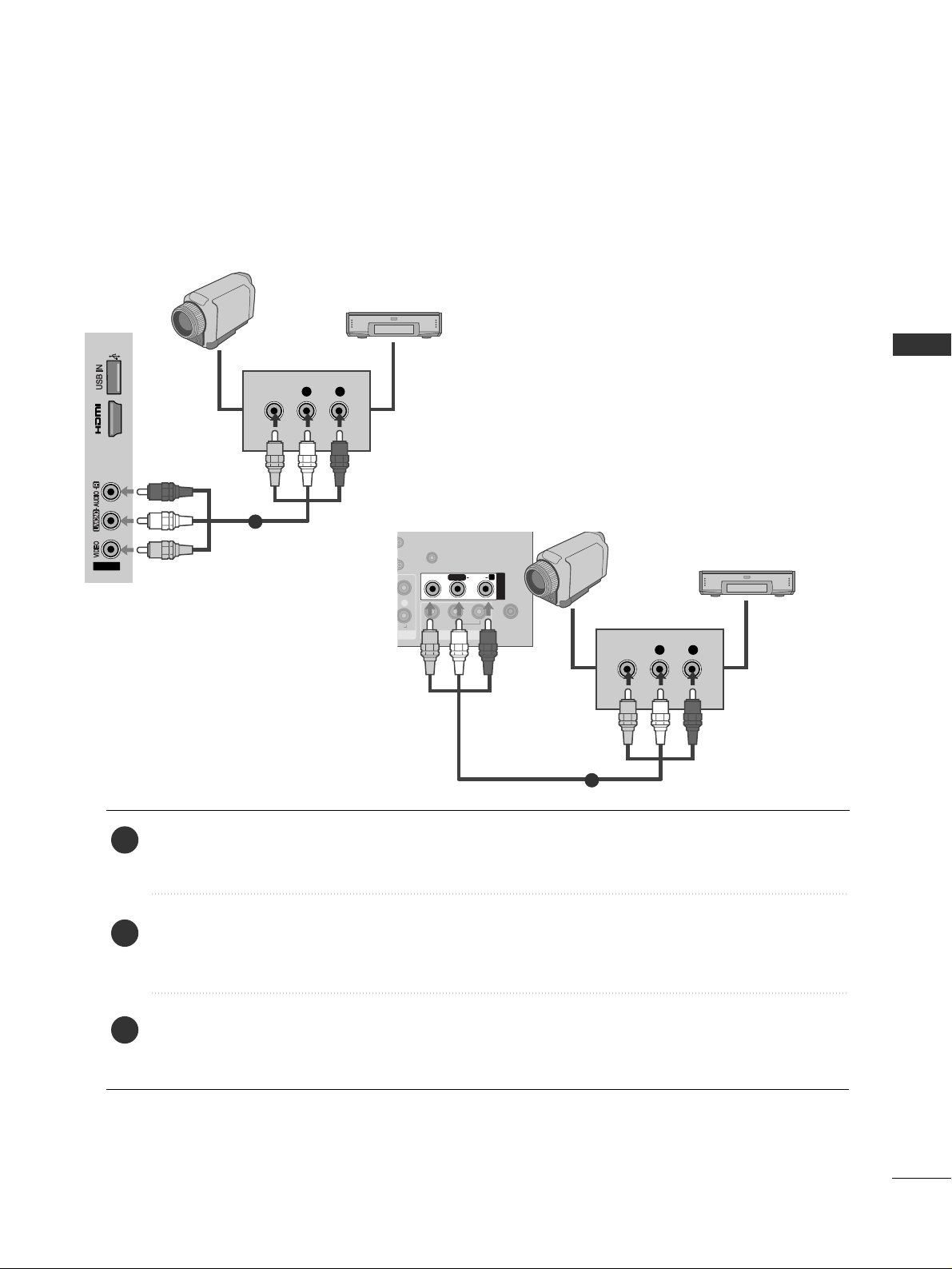
OTHER A/V SOURCE SETUP
Connect the
AA UU DDII OO/VVIIDD EEOO
jacks between TV and external equipment. Match the jack colours
.
(
Video = yellow, Audio Left = white, and Audio Right = red
)
Select
AA VV11
input source with using the
IINNPPUUTT
button on the remote control.
If connected to
AA VV IINN 22
, select
AA VV22
input source.
Operate the corresponding external equipment.
Refer to external equipment operating guide.
1
2
3
AV IN2
IN 3
L R
VIDEO
Camcorder
Video Game Set
1
R
O
AUDIO IN
(RGB/DVI)
AV OUT
VARIABLE AUDIO OUT
L/L/MONOMONO
R
AUDIOAUDIO
VIDEOVIDEO
AV IN1
L R
VIDEO
ANTENNA
IN
Camcorder
Video Game Set
1
or
18
EXTERNAL EQUIPMENT SETUP
EXTERNAL EQUIPMENT SETUP
EXTERNAL STEREO SETUP
L R
AUDIO
VIDEO
AUDIO
/MONO
AV
VARIABLE AUDIO OUT
OUT
IN1
GG
When connecting with external audio equipments, such as
amplifiers or speakers, please turn the TV speakers off.
(
GG
pp ..7777
)
GG
Select
VVaarriiaabbllee OOuutt
in
AAUUDDIIOO
menu to connect the
VVAARRIIAABB LLEE AAUU DDIIOO OO UUTT
jacks.(
GG
pp ..7788
)
NOTE
!
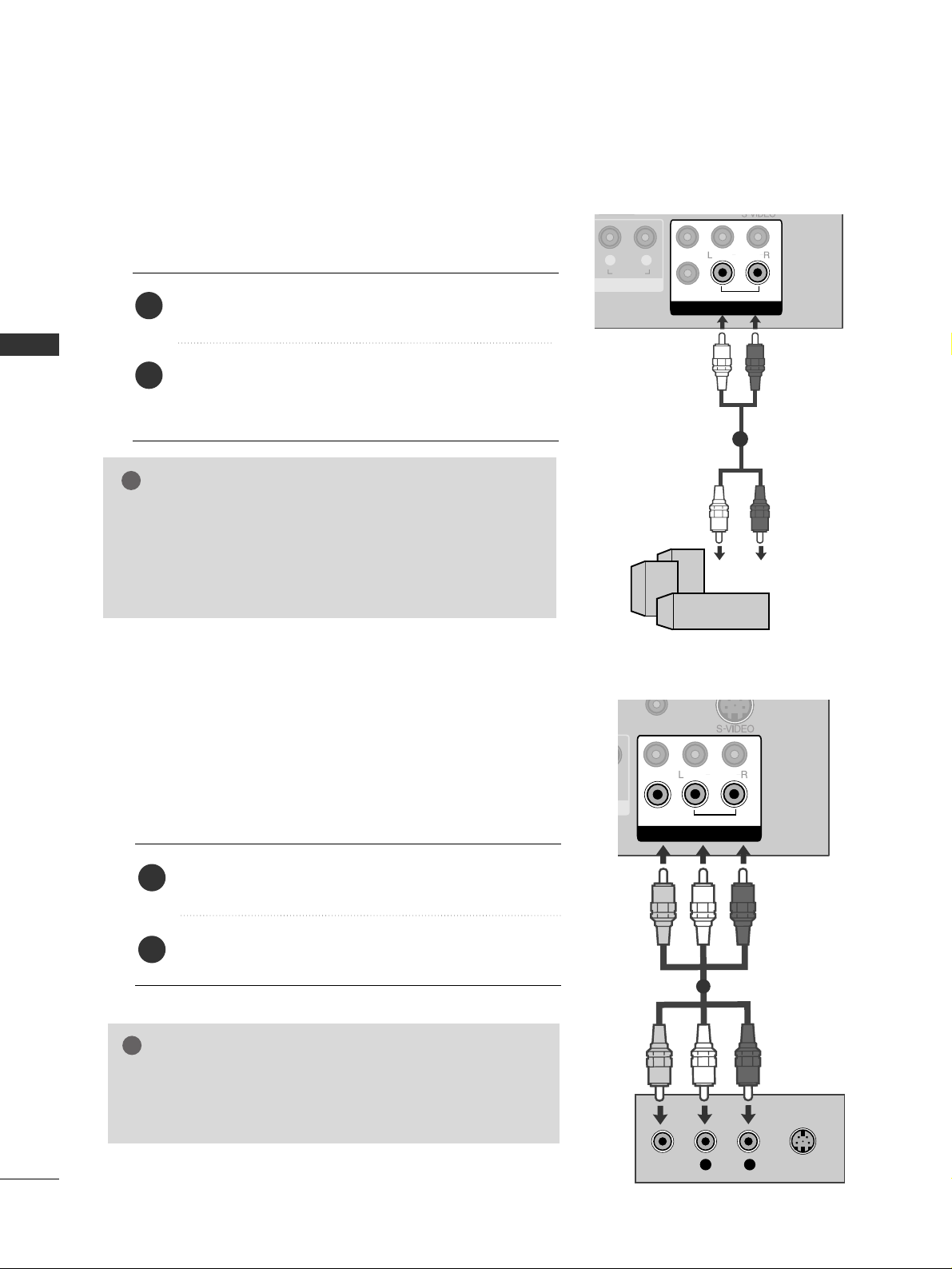
Use to connected either an external amplifier, or add a sub-woofer
to your surround sound system.
Connect the input jack of the stereo amplifier to the
VVAARRIIAABB LLEE AAUU DDIIOO OO UUTT
jacks on the TV.
Set up your speakers through your analog stereo
amplifier, according to the instructions provided with
the amplifier.
2
1
11
AV OUTPUT SETUP
The TV has a special signal output capability which allows you
to hook up the second TV or monitor.
VIDEO
AUDIO
/MONO
AUDIO IN
(RGB/DVI)
AV
VARIABLE AUDIO OUT
OUT
IN1
L R
S-VIDEO
VIDEO
Connect the second TV or monitor to the TV’s
AAVV OOUUTT
jacks.
See the Operating Manual of the second TV or monitor
for further details regarding that device’s input settings.
GG
Component, RGB, HDMI input sources cannot be used for
AV out.
GG
We recommend to use the AV OUT jacks for VCR recording.
NOTE
!
2
1
1
EXTERNAL EQUIPMENT SETUP
19
EXTERNAL EQUIPMENT SETUP
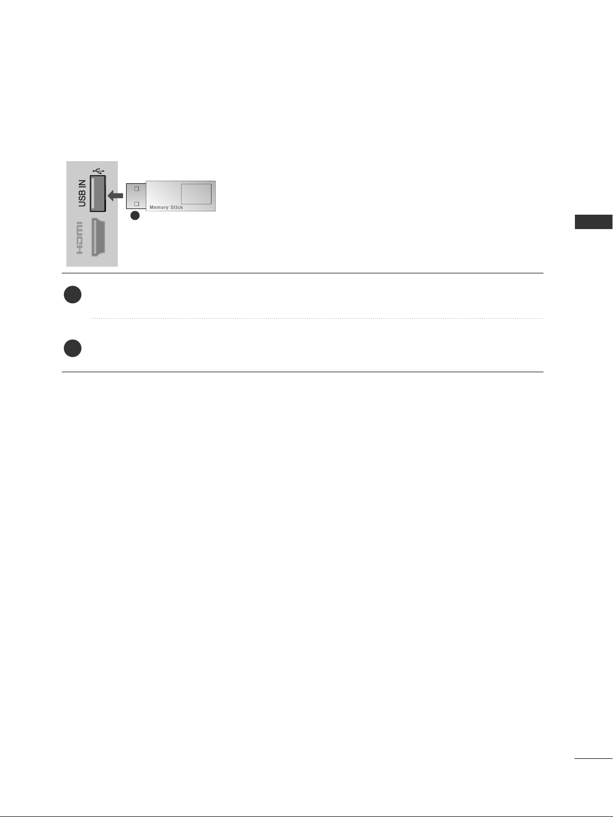
USB IN SETUP
IN 3
Connect the USB device to the
UUSSBB II NN
jack on the TV.
After connecting the
UUSSBB II NN
jacks, you use the
UU SS BB
function. (
GG
pp..4466
)
2
1
1
■
Here shown may differ from your TV.
20
EXTERNAL EQUIPMENT SETUP
EXTERNAL EQUIPMENT SETUP
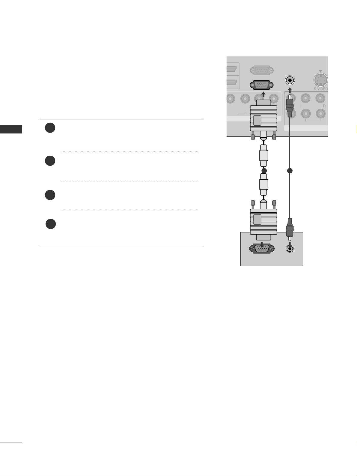
PC SETUP
This TV provides Plug and Play capability, meaning that the PC
adjusts automatically to the TV's settings.
Connecting with a D-sub 15 pin cable
4
Connect the RGB output of the PC to the
RRGG BB IINN
((PPCC ))
jack on the TV.
Connect the PC audio output to the
AA UUDDIIOO II NN
((RRGGBB//DDVV II))
jack on the TV.
Turn on the TV and the PC.
Select
RRGG BB
input source using the
IINNPPUUTT
button on
the remote control.
2
3
1
LP
BPR
R
AUDIO
VIDEO
AUDIO
/MONO
RS-232C IN
(CONTROL)
AUDIO IN
(RGB/DVI)
AV
VARIABLE AUDIO OUT
OU
IN
RGB IN
(PC)
RGB OUTPUT
AUDIO
1 2
21
EXTERNAL EQUIPMENT SETUP
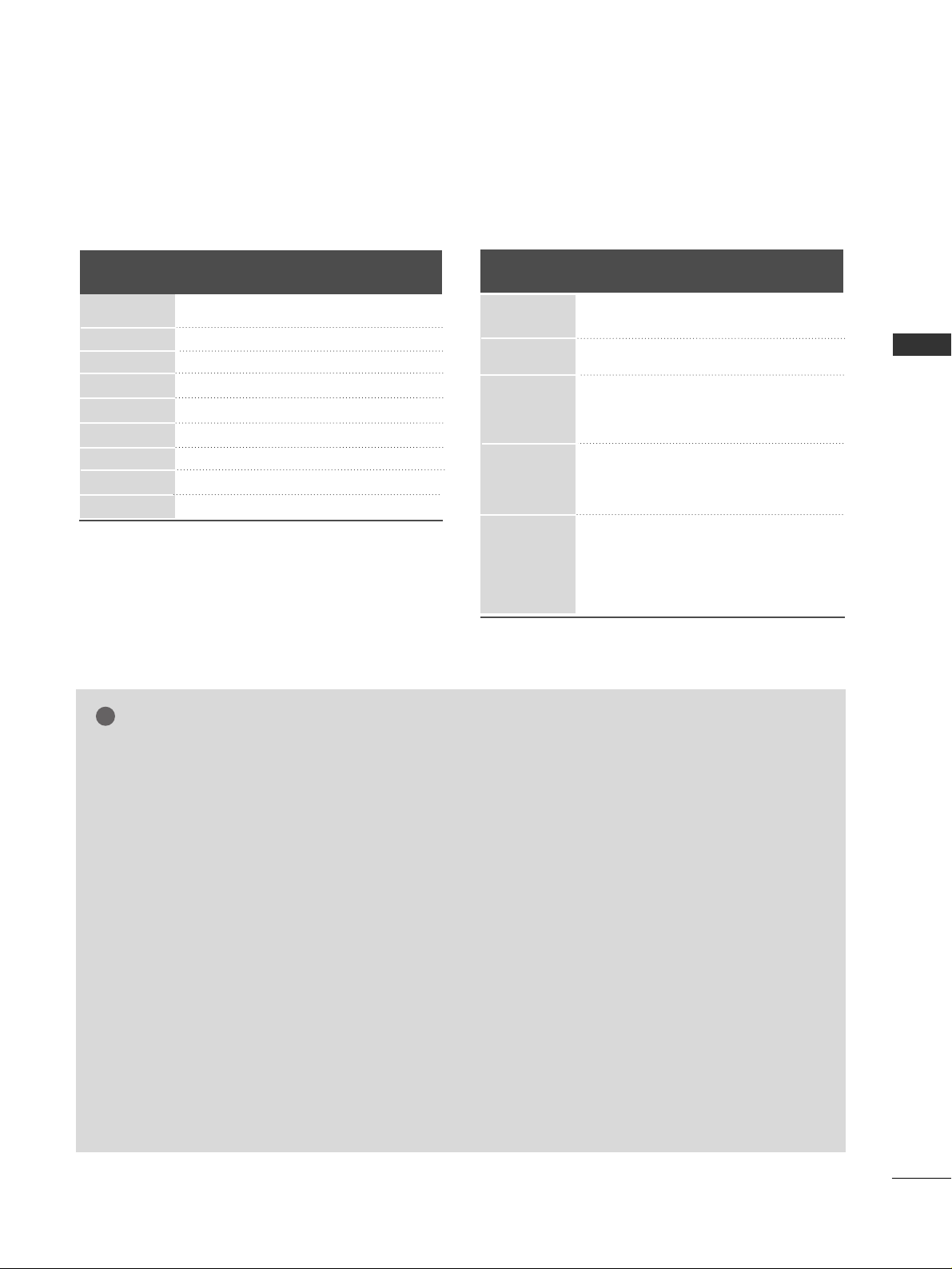
Resolution
720x480
720x576
1280x720
1920x1080i
1920x1080p
HDMI-DTV mode
Horizontal Vertical
Frequency(kHz) Frequency(Hz)
31.47 59.94
31.50 60.00
31.25 50.00
44.96 59.94
45.00 60.00
37.50 50.00
33.75 60.00
33.72 59.94
28.125 50.00
67.432 59.94
67. 5 60
56.250 50
27 24
33.75 30
Resolution
640x350
720x400
640x480
800x600
1024x768
1280x768
1360x768
1280x1024
1920x1080
RGB-PC mode
Horizontal Vertical
Frequency(kHz) Frequency(Hz)
31.468 70.09
31.469 70.09
31.469 59.94
37.879 60.317
48.363 60.004
47.776 59.87
47. 720 59.799
63.668 59.895
66.587 59.934
Supported Display Resolution
NOTE
!
GG
Avoid keeping a fixed image on the TV ’s screen
for prolonged periods of time.The fixed image
may become permanently imprinted on the
screen;use a screen saver when possible.
GG
There may be interference relating to resolution,
vertical pattern, contrast or brightness in PC
mode. Change the PC mode to another resolution or change the refresh rate to another rate
or adjust the brightness and contrast on the
menu until the picture is clear. If the refresh rate
of the PC graphic card can not be changed,
change the PC graphic card or consult the manufacturer of the PC graphic card.
GG
The synchronization input waveform for
Horizontal and Vertical frequencies are separate.
GG
If the resolution of PC is over SXGA, there will
be no picture on the TV.(only HD Models)
GG
Connect the audio cable from the PC to the
Audio input on the TV.(Audio cables are not
included with the TV).
GG
If you use too long an RGB-PC cable, there may
be interference on the screen. We recommend
using under 5m of the cable. This provides the
best picture quality.
GG
We recommend using
1920x1080, 60Hz
for the
PC mode, these should provide the best picture
quality.
GG
HDMI mode supports PCM audio format only.
GG
If the Audio setting is set to
Dolby/DTS/Bitstream in some DVDP/STB, make
sure to change the setting to PCM.
22
EXTERNAL EQUIPMENT SETUP
EXTERNAL EQUIPMENT SETUP
EXTERNAL EQUIPMENT SETUP
1
MENU
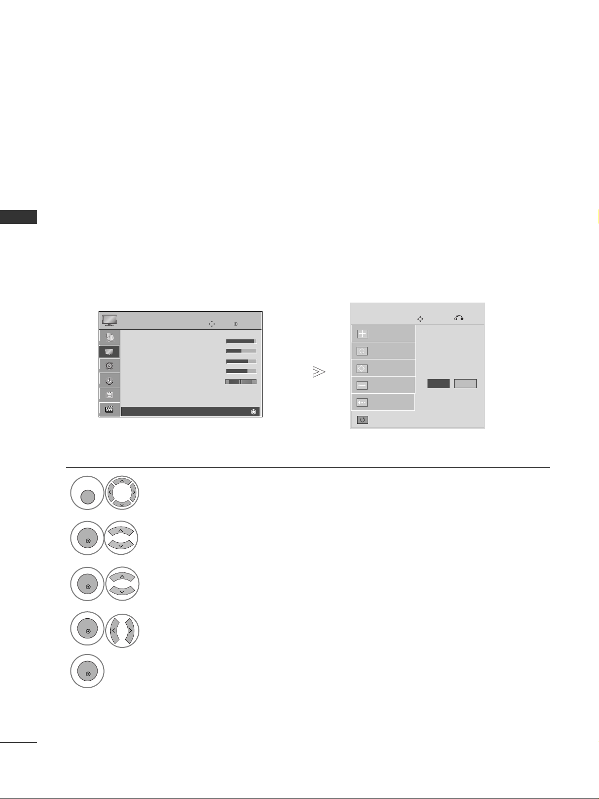
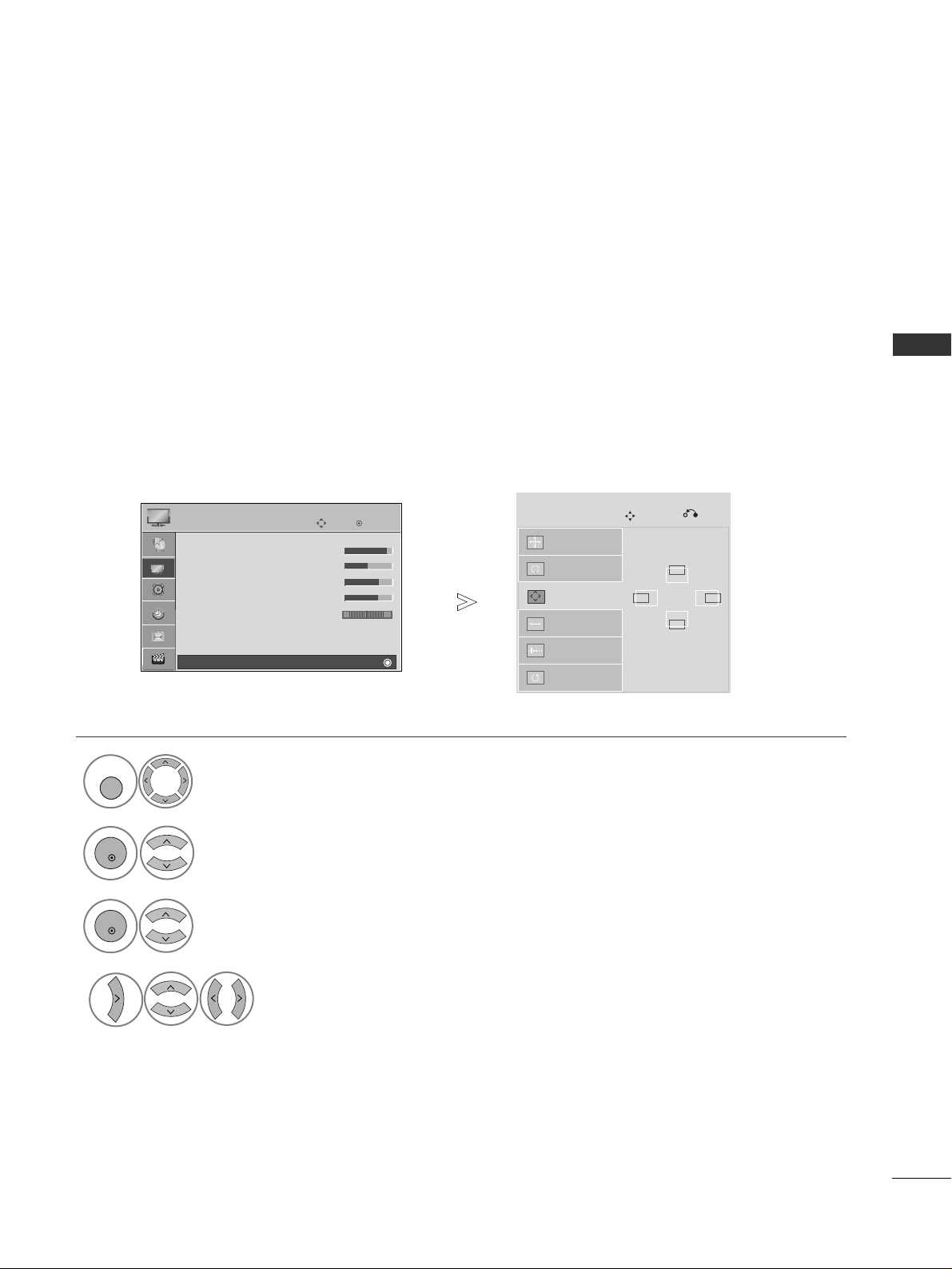
Screen Setup for PC mode
Returns Position, Size and Phase to the factory default settings.
This function works in the following mode : RGB[PC], Component(except 480i, 576i).
Screen Reset
Select
PP IICCTT UURR EE
.
Select
SS ccrreeeenn
.
3
Select
RRee ssee tt
.
To Set
Auto Config.
Screen
Move
Prev.
Resolution
Position
Size
Phase
Reset
G
2
OK
OK
• Press the
MMEE NN UU
button to return to normal TV viewing.
• Press the
RREE TTUURRNN
button to move to the previous menu screen.
Select
YYee ss
.
Run
RRee ssee tt
.
4
OK
5
OK
OK
Move
• Contrast 90
• Brightness 50
• Sharpness 60
• Colour 60
• Tint 0
• Advanced Control
• Picture Reset
Screen
PICTURE
RG
E
Screen
Yes No
23
EXTERNAL EQUIPMENT SETUP
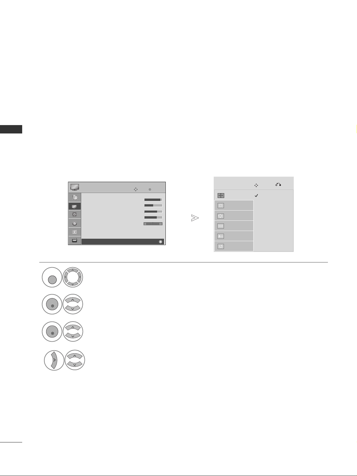
If the picture is not clear after auto adjustment and especially if characters are still trembling, adjust the
picture phase manually.
PP oossii ttii oonn
operates in Component(except 480i, 576i), RGB mode.
SS iizzee,PP hh aa ssee
operate only in RGB mode.
Adjustment for screen Position, Size, Phase
Select
PP IICCTT UURR EE
.
Select
SS ccrreeeenn
.
Select
PP oo ssiittii oo nn, SS ii zzee
or
PP hhaass ee
.
Make appropriate adjustments.
Auto Config.
Resolution
Position
G
Size
Phase
Reset
GF
D
E
Screen
Move
Prev.
1
MENU
3
4
2
OK
OK
• Press the
MMEE NN UU
button to return to normal TV viewing.
• Press the
RREETT UU RRNN
button to move to the previous menu screen.
OK
Move
• Contrast 90
• Brightness 50
• Sharpness 60
• Colour 60
• Tint 0
• Advanced Control
• Picture Reset
Screen
PICTURE
RG
E
Screen
24
EXTERNAL EQUIPMENT SETUP
EXTERNAL EQUIPMENT SETUP
To view a normal picture, match the resolution of RGB mode and selection of PC mode.
This function works in the following mode: RGB[PC]
Selecting Resolution
Select
PP IICCTT UURR EE
.
Select
SS ccrreeeenn
.
Select
RRee ssoolluuttii oo nn
.
Select the desired resolution.
Auto Config.
Resolution
G
Position
Size
Phase
Reset
Screen
Move
Prev.
1
MENU
3
4
2
OK
OK
• Press the
MMEE NN UU
button to return to normal TV viewing.
• Press the
RREETT UU RRNN
button to move to the previous menu screen.
1024 x 768
1280 x 768
1360 x 768
OK
Move
• Contrast 90
• Brightness 50
• Sharpness 60
• Colour 60
• Tint 0
• Advanced Control
• Picture Reset
Screen
PICTURE
RG
E
Screen

25
EXTERNAL EQUIPMENT SETUP
Automatically adjusts the picture position and minimizes image instability. After adjustment, if the image is
still not correct, your TV is functioning properly but needs further adjustment.
AAuutt oo ccoo nn ffii gguurree
This function is for automatic adjustment of the screen position, size, and phase.
The displayed image will be unstable for a few seconds while the auto configuration is in progress.
Auto Configure (RGB [PC] mode only)
• If the position of the image is still not correct,
try Auto adjustment again.
• If picture needs to be adjusted again after Auto
adjustment in RGB(PC), you can adjust the
PP oo ssiittii oo nn, SS ii zzee
or
PP hhaass ee
.
Select
PP IICCTT UURR EE
.
Select
SS ccrreeeenn
.
Select
AA uutt oo CCoonnffiigg ..
.
Auto Config.
G
Resolution
Position
Size
Phase
Reset
Screen
Move
Prev.
To Set
1
MENU
3
2
OK
OK
• Press the
MMEE NN UU
button to return to normal TV viewing.
• Press the
RREETT UU RRNN
button to move to the previous menu screen.
Select
YYee ss
.
Run
AA uutt oo CCoonnffiigg ..
.
4
OK
5
OK
Yes No
OK
Move
• Contrast 90
• Brightness 50
• Sharpness 60
• Colour 60
• Tint 0
• Advanced Control
• Picture Reset
Screen
PICTURE
RG
E
Screen
26
WATCHING TV / PROGRAMME CONTROL
V MODE
MUTE
Q.VIEW
WATCHING TV / PROGRAMME CONTROL
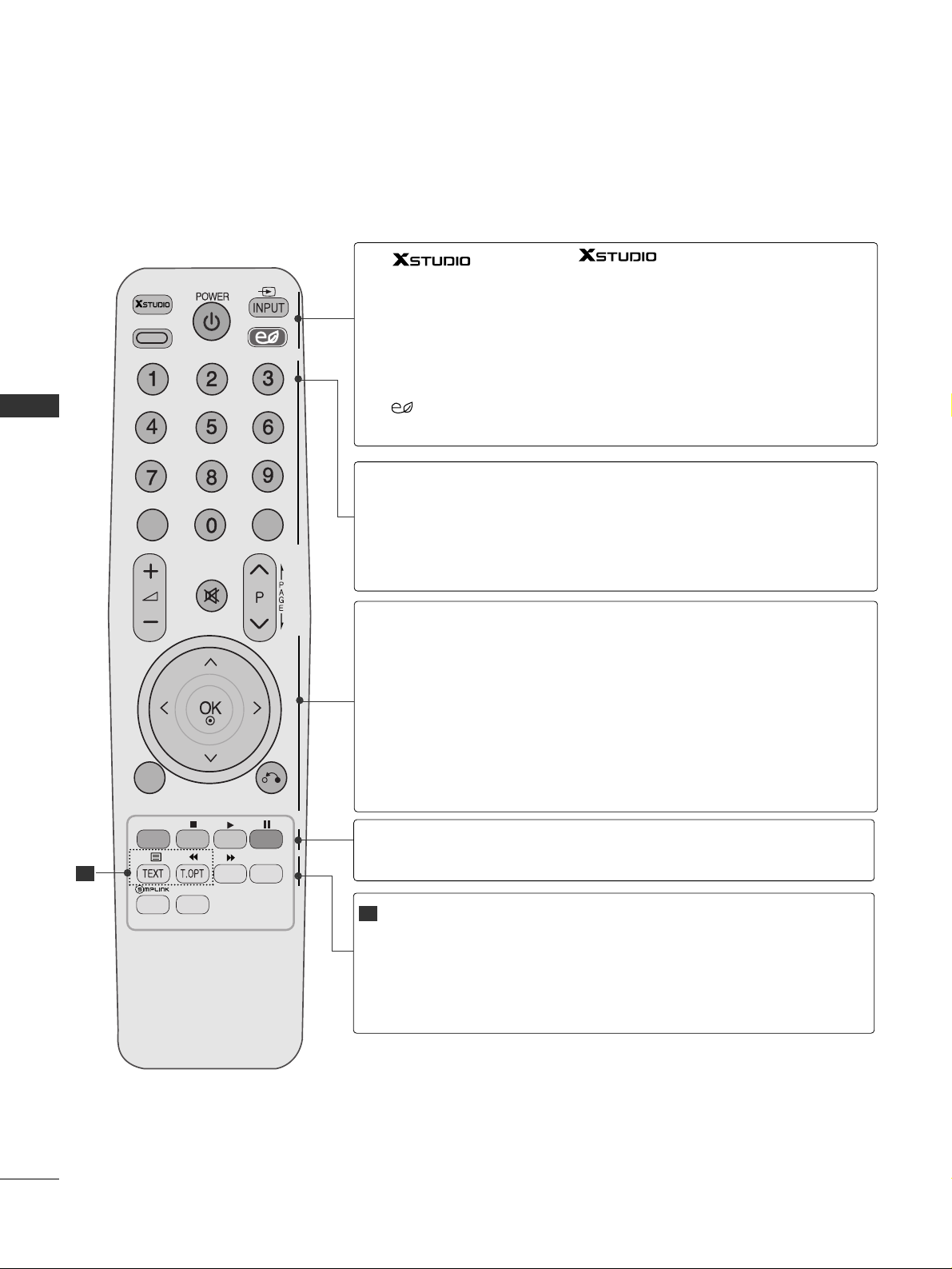
REMOTE CONTROL KEY FUNCTIONS
When using the remote control, aim it at the remote control sensor on the TV.
AV MODE
POWER
INPUT
ENERGY
SAVING
Enter to the mode.
It helps you select and set images and sounds when connecting AV devices.(
GG
pp .. 44 55
)
Switches the TV on from standby or off to standby.
External input mode rotate in regular sequence.(
GG
pp .. 33 88
)
Adjust the energy saving mode of the TV.(
GG
pp .. 66 11
)
0~9 number
button
LIST
Q.VIEW
Selects a programme.
Selects numbered items in a menu.
Displays the programme table.(
GG
pp .. 33 66
)
Returns to the previously viewed programme.
THUMBSTICK
(Up/Down/Left/Right)
OK
MENU
RETURN
Allows you to navigate the on-screen menus and adjust
the system settings to your preference.
Accepts your selection or displays the current mode.
Selects a menu.
Clears all on-screen displays and returns to TV viewing
from any menu.(
GG
pp .. 33 00
)
Allows the user to move return one step in an interactive
application or other user interaction function.
1
Coloured
buttons
These buttons are used for teletext (on
TT EELLEETTEEXXTT
models only) ,
PP rr oogg rr aammmmee eeddiitt
.
TELETEXT
BUTTONS
FAV
MARK
These buttons are used for teletext.
For further details, see the ‘Teletext’ section.(
GG
pp .. 88 55
)
Displays the selected favourite programme.
Check and un-check programmes in the USB menu.
1
AV MODE
LIST
MUTE
ENERGY SAVING
Q.VIEW
MENU
Q.MENU
RETURN
MARK
FAV
27
WATCHING TV / PROGRAMME CONTROL
AV MODEV MODE
ENERGY SAVING
RETURN
MENU
Q.MENU
MARK
MUTEMUTE
LIST
Q.VIEWQ.VIEW
FAV
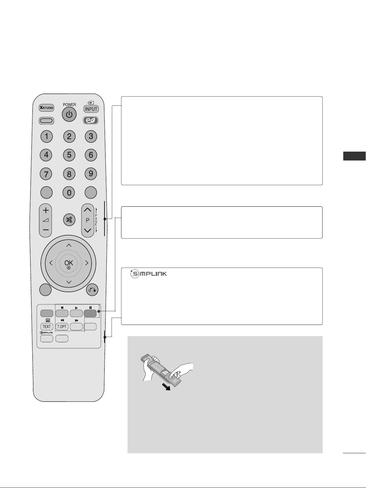
VOLUME UP
/DOWN
MUTE
Programme
UP/DOWN
PAG E
UP/DOWN
Adjusts the volume.
Switches the sound on or off.
Selects a programme.
Move from one full set of screen information to the next
one.
Q. MENU
See a list of AV devices connected to TV.
When you toggle this button, the Simplink menu
appears at the screen.(
GG
pp .. 44 00
)
Select the desired quick menu source.(Aspect Ratio,
Clear Voice II, Picture Mode, Sound Mode, AUDIO, Sleep
Timer, Favourite, USB Device) (
GG
pp .. 22 99
)
Installing Batteries
■
Open the battery compartment cover on the back and install the
batteries matching correct polarity (+with +,-with -).
■
Install two 1.5V AAA batteries. Do not mix old or used batteries
with new ones.
■
Close cover.
SIMPLINK /
USB Menu
control buttons
Controls SIMPLINK or USB. menu.

28
WATCHING TV / PROGRAMME CONTROL
WATCHING TV / PROGRAMME CONTROL
TURNING ON THE TV
Firstly, connect the power cord correctly and check the main power on the TV.
At this stage, the TV switches to standby mode.
In standby mode to turn TV on, press the
rr
/ I, INPUT or P
D E
button on the TV or press the
POWER, INPUT, P or NUMBER button on the remote control and the TV will switch on.
2
1
Initializing setup
Note:
a. If you close without completing the initial setting, the Initial Setting menu can be displayed again.
b. “Store Demo” mode is only for shop display and not for general customer use.
c. "Home Use” mode is the optimal setting for home environments, and is the TV's default mode.
d. "Store Demo" mode is the optimal setting for store environments. If a user modifies image quality data,
“Store Demo” mode initializes the product to the image quality set by us after a certain period of time.
e. The mode (Home Use, Store Demo) can be changed by executing Mode Setting in the OPTION menu.
If the OSD (On Screen Display) is displayed on the screen after turning on the TV, you can adjust the
LL aa nngguu aa ggee, MMooddee SSee ttttii nngg, AA uutt oo TTuu nn iinn gg
.
- When your TV is turned on, you will be able to use its features.
PROGRAMME SELECTION
Press the
PP
or NUMBER buttons to select a programme
number.
1
VOLUME ADJUSTMENT
Press the
++ or--
button to adjust the volume.
If you wish to switch the sound off, press the MUTE button.
You can cancel this function by pressing the MUTE,
++ or--
, AV Mode button.
1
 Loading...