

LG 30FZ1DC, 32FZ1DC-UB User Manual

Color television
OWNER’S MANUAL
Please read this manual carefully and completely before
operating your TV.
Retain this manual for future reference.
Record model number and serial number of the TV in the
spaces provided below.
See the label attached on the back cover and relate this
information to your dealer if you require service.
Model Number :
Serial Number :
MODELS: 30FZ1DC
32FZ1DC-UB
LG Electronics U.S.A., Inc.
R
TruSurround XT
PAGE 2
WARNING/CAUTION:
TO REDUCE THE RISK OF ELECTRIC SHOCK DO NOT REMOVE COVER (OR BACK). NO USER SERVICEABLE PARTS INSIDE.
REFER TO QUALIFIED SERVICE PERSONNEL.
The lightning flash with arrowhead symbol, within an equilateral triangle, is intended to alert the user to the presence
of uninsulated “dangerous voltage” within the product’s enclosure that may be of sufficient magnitude to constitute a
risk of electric shock to persons.
The exclamation point within an equilateral triangle is intended to alert the user to the presence of important operating
and maintenance (servicing) instructions in the literature accompanying the appliance.
WARNING/CAUTION:
TO PREVENT FIRE OR SHOCK HAZARDS, DO NOT EXPOSE THIS PRODUCT TO RAIN OR MOISTURE.
POWER CORD POLARIZATION:
CAUTION: TO PREVENT ELECTRIC SHOCK, MATCH WIDE BLADE OF PLUG TO WIDE SLOT, FULLY INSERT.
ATTENTION: POUR ÉVITER LES CHOCS ÉLECTRIQUES, INTRODUIRE LA LAME LA PLUS LARGE DE LA FICHE DANS LA BORNE
CORRESPONDANTE DE LA PRISE ET POUSSER JUSQU’AU FOND.
NOTE TO CABLE/TV INSTALLER:
This reminder is provided to call the CATV system installer’s attention to Article 820-40 of the National Electric Code
(U.S.A.). The code provides guidelines for proper grounding and, in particular, specifies that the cable ground shall be
connected to the grounding system of the building, as close to the point of the cable entry as practical.
REGULATORY INFORMATION:
This equipment has been tested and found to comply with the limits for a Class B digital device, pursuant to Part 15 of
the FCC Rules. These limits are designed to provide reasonable protection against harmful interference when the equipment is operated in a residential installation. This equipment generates, uses and can radiate radio frequency energy
and, if not installed and used in accordance with the instruction manual, may cause harmful interference to radio communications. However, there is no guarantee that interference will not occur in a particular installation. If this equipment does cause harmful interference to radio or television reception, which can be determined by turning the equipment off and on, the user is encouraged to try to correct the interference by one or more of the following measures:
• Reorient or relocate the receiving antenna.
• Increase the separation between the equipment and receiver.
• Connect the equipment into an outlet on a circuit different from that to which the
receiver is connected.
• Consult the dealer or an experienced radio/TV technician for help.
Any changes or modifications not expressly approved by the party responsible for compliance could void the user’s
authority to operate the equipment.
CAUTION:
Do not attempt to modify this product in any way without written authorization from Zenith Electronics Corporation.
Unauthorized modification could void the user’s authority to operate this product.
COMPLIANCE:
The responsible party for this product’s compliance is:
LG Electronics U.S.A., Inc
1000 Sylvan Avenue, Englewood Cliffs, NJ 07632
1-800-243-0000
http://www.lgusa.com

PAGE 3
IMPORTANT SAFETY INSTRUCTIONS
Important safety instructions shall be provided with each apparatus. This information shall be given in a separate booklet or
sheet, or be located before any operating instructions in an instruction for installation for use and supplied with the apparatus.
This information shall be given in a language acceptable to the country where the apparatus is intended to be used.
The important safety instructions shall be entitled “Important Safety Instructions”. The following safety instructions shall be
included where applicable, and, when used, shall be verbatim as follows. Additional safety information may be included by
adding statements after the end of the following safety instruction list. At the manufacturer’s option, a picture or drawing
that illustrates the intent of a specific safety instruction may be placed immediately adjacent to that safety instruction :
(Continued on next page)
1. Read these instructions.
2. Keep these instructions.
3. Heed all warnings.
4. Follow all instructions.
5. Do not use this apparatus near water.
6. Clean only with dry cloth.
7. Do not block any ventilation openings. Install in accordance with the manufacturer’s instructions.
8. Do not install near any heat sources such as radiators, heat registers, stoves, or other apparatus (including amplifiers)that produce heat.
9. Do not defeat the safety purpose of the polarized or grounding-type plug. A polarized plug has two blades with
one wider than the other. A grounding type plug has two blades and a third grounding prong, The wide blade or
the third prong are provided for your safety. If the provided plug does not fit into your outlet, consult an electrician for replacement of the obsolete outlet.
10. Protect the power cord from being walked on or pinched particularly at plugs, convenience receptacles, and the
point where they exit from the apparatus.
11. Only use attachments/accessories specified by the manufacturer.
12. Use only with the cart, stand, tripod, bracket, or table specified by the manufacturer, or sold with the appara-
tus. When a cart is used, use caution when moving the cart/apparatus combination to avoid injury from tip-over.
PORTABLE CART WARNING
IMPORTANT SAFETY INSTRUCTIONS

PAGE 4
13. Unplug this apparatus during lightning storms or when unused for long periods of time.
14. Refer all servicing to qualified service personnel. Servicing is required when the apparatus has been damaged in
any way, such as power-supply cord or plug is damaged, liquid has been spilled or objects have fallen into the
apparatus, the apparatus has exposed to rain or moisture, does not operate normally, or has been dropped.
15. CAUTION concerning the Power Cord :
Most appliances recommend they be placed upon a dedicated circuit; that
is, a single outlet circuit which powers only that appliance and has no
additional outlets or branch circuits. Check the specification page of
this owner's manual to be certain.
Do not overload wall outlets. Overloaded wall outlets, loose or damaged
wall outlets, extension cords, frayed power cords, or damaged or
cracked wire insulation are dangerous. Any of these conditions could
result in electric shock or fire. Periodically examine the cord of your
appliance, and if its appearance indicates damage or deterioration,
unplug it, discontinue use of the appliance, and have the cord replaced
with an exact replacement part by an authorized servicer.
Protect the power cord from physical or mechanical abuse, such as being
twisted, kinked, pinched, closed in a door, or walked upon. Pay
particular attention to plugs, wall outlets, and the point where the
cord exits the appliance.
16. Outdoor Use Marking :
WARNING - To Reduce The Risk Of Fire Or Electric Shock, Do Not Expose This Appliance To Rain Or Moisture.
17. Wet Location Marking :
Apparatus shall not be exposed to dripping or splashing and no objects filled with liquids, such as vases, shall be
placed on the apparatus.
IMPORTANT SAFETY INSTRUCTIONS

PAGE 5
Table of Contents
Safety Warnings . . . . . . . . . . . . . . . . . . . . . . . . . . . .2
Important Safety Instructions . . . . . . . . . . . . . . . . .3-4
Step 1. Hook Up TV
Front Panel Controls . . . . . . . . . . . . . . . . . . . . . . . . .6
Rear Connections Panel . . . . . . . . . . . . . . . . . . . . . . .7
Front Connections Panel (FRONT VIDEO) . . . . . . . . . . . .8
ANT/Cable Service Hookup . . . . . . . . . . . . . . . . . . . . .9
Cable Box Connections . . . . . . . . . . . . . . . . . . . . . . .10
VCR Connections . . . . . . . . . . . . . . . . . . . . . . . . . . .11
DVD Player . . . . . . . . . . . . . . . . . . . . . . . . . . . . . .12
Set-top Box Hookup . . . . . . . . . . . . . . . . . . . . . . . .13
Digital Audio Output . . . . . . . . . . . . . . . . . . . . . . . .14
HDMI . . . . . . . . . . . . . . . . . . . . . . . . . . . . . . . . . .15
Remote Control Functions in TV Mode . . . . . . . . . . .16-17
Turning the TV on . . . . . . . . . . . . . . . . . . . . . . . . . .18
On-Screen Displays . . . . . . . . . . . . . . . . . . . . . . . . .18
Step 2. Customize your TV’s Features
SETUP Menu
EZ Scan (Channel Search) . . . . . . . . . . . . . . . . . . . .19
Channel Edit . . . . . . . . . . . . . . . . . . . . . . . . . . . .20
DTV Signal . . . . . . . . . . . . . . . . . . . . . . . . . . . . . .21
Degaussing the screen . . . . . . . . . . . . . . . . . . . . . .21
Channel Label Setup . . . . . . . . . . . . . . . . . . . . . . .22
Input Source Selection . . . . . . . . . . . . . . . . . . . . . 23
VIDEO Menu
EZ Picture . . . . . . . . . . . . . . . . . . . . . . . . . . . . . .24
Manual Video Control . . . . . . . . . . . . . . . . . . . . . . .25
Color Temperature . . . . . . . . . . . . . . . . . . . . . . . . .26
XD . . . . . . . . . . . . . . . . . . . . . . . . . . . . . . . . . . .26
Video Preset . . . . . . . . . . . . . . . . . . . . . . . . . . . .26
AUDIO Menu
Audio Language . . . . . . . . . . . . . . . . . . . . . . . . . .27
EZ SoundRite . . . . . . . . . . . . . . . . . . . . . . . . . . . .27
Stereo/SAP Broadcasts Setup . . . . . . . . . . . . . . . . . .28
EZ Sound . . . . . . . . . . . . . . . . . . . . . . . . . . . . . .28
Manual Sound Control . . . . . . . . . . . . . . . . . . . . . .29
TV Speaker on/off Setup . . . . . . . . . . . . . . . . . . . . .29
Front Surround . . . . . . . . . . . . . . . . . . . . . . . . . . .30
TIME Menu
Auto Clock Setup . . . . . . . . . . . . . . . . . . . . . . . . .31
Manual Clock Setup . . . . . . . . . . . . . . . . . . . . . . . .32
TV Turn Off Time Setup . . . . . . . . . . . . . . . . . . . . .33
TV Turn On Time Setup . . . . . . . . . . . . . . . . . . . . . .34
Sleep Timer Setup . . . . . . . . . . . . . . . . . . . . . . . . .35
Auto off . . . . . . . . . . . . . . . . . . . . . . . . . . . . . . .36
OPTION Menu
Aspect Ratio Control . . . . . . . . . . . . . . . . . . . . . . .37
Captions . . . . . . . . . . . . . . . . . . . . . . . . . . . . . . .38
Caption/Text . . . . . . . . . . . . . . . . . . . . . . . . . . . .39
Caption Option Menu . . . . . . . . . . . . . . . . . . . . . . .40
On-Screen Menu Languages . . . . . . . . . . . . . . . . . . .41
Velocity Modulation . . . . . . . . . . . . . . . . . . . . . . . .42
Tilt . . . . . . . . . . . . . . . . . . . . . . . . . . . . . . . . . .42
Cinema 3:2 Mode Setup . . . . . . . . . . . . . . . . . . . . .43
EZ Demo . . . . . . . . . . . . . . . . . . . . . . . . . . . . . . .44
LOCK Menu
Parental Lock Setup . . . . . . . . . . . . . . . . . . . . .45-46
Step 3. Miscellaneous
Programming the Remote . . . . . . . . . . . . . . . . . . . . .47
Programming Codes . . . . . . . . . . . . . . . . . . . . . .48-50
Maintenance . . . . . . . . . . . . . . . . . . . . . . . . . . .51-52
Troubleshooting . . . . . . . . . . . . . . . . . . . . . . . . .53-54
Glossary . . . . . . . . . . . . . . . . . . . . . . . . . . . . . .55-56
Product Specifications . . . . . . . . . . . . . . . . . . . . . .57
Warranty . . . . . . . . . . . . . . . . . . . . . . . . . . . . . . . .60
Note: Design and specifications are subject to change without prior notice.

PAGE 6
Front Panel Controls
power
Standby indicator (Illuminates brightly when the TV is
in standby mode. Dims when the TV is switched on.)
Remote control sensor
TV/VIDEO
menu
vol left/ right
Volume(
G) button increases the sound level and vol-
ume(
F) button decreases the sound level.
ch (Channel) up / down
1
2
3
4
These buttons work just as they do on your
remote control.
5
6
7
1
2
4
3
6
7
5
- Here shown may be somewhat different from your TV.
TV/VIDEO
MENU
VOL
CH

PAGE 7
Rear Connections Panel
Mini glossary
JACK A connection on the back of a TV, VCR, or any other A/V device. This includes the RF jack and the Audio/Video jacks that are color-
coded.
SIGNAL Picture and sound traveling through cable, or over the air, to your television screen.
CALIBRATION
DIGITAL
AUDIO OUTPUT
OPTICAL
DVD/DTV INPUT
VIDEO
AUDIO
L(MONO) R
ANTENNA
HDMI/DVI
DIGITAL
AUDIO INPUT
OPTICAL
(DVI)
PR
COMPONENT1
(480i/480p/720p/1080i)
COMPONENT2
S-VIDEO
P
B
Y
L
R
IN1
IN2
AUDIO
P
R
PB
Y
L
R
AUDIO
+75 Ω
INPUT
IN3
S-Video In
A connection available
with some high-end
equipment that provides
even better picture
quality for Video 1, 2.
RF Connectors:
Antenna Input,
Used to connect
cable or antenna signals to the television,
either directly or
through your cable
box.
Video 1, 2 and 3 Inputs
Connects the video signals
from various types of
equipment.
Y, P
B, PR
DVD Component Video and HD
Component Video
Some top-of-the-line DVD players use
what is called “component video,” for
extremely accurate picture reproduction. Refer to your DVD manual for
further information.
- Connecting external equipment to your TV.
- Here shown may be somewhat different from your TV.
Left/Right Audio
Used for stereo sound
from various types of
equipment.
Component Left/Right
Audio
Used for stereo sound from
various types of equipment.
HDMI/DVI Input
Used to connect
from a DTV source.
Digital Audio
Output Optical
Connects to external
audio equipment
like a home theater
system.
Digital Audio Input
Optical
Connects to digital
audio from various
types of equipment.
PAGE 8
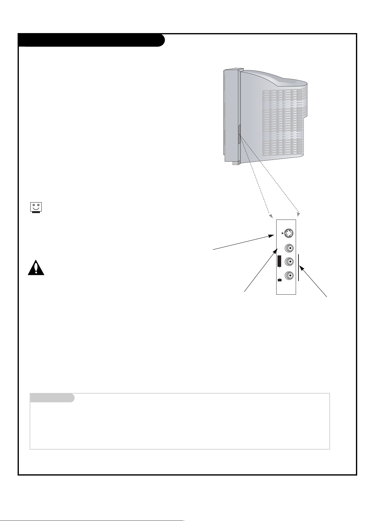
Front Connections Panel
There are four jacks on the lower-right front
front of your TV that make connecting
Audio/Video devices like video games and
camcorders very simple.
The jacks are like those found on the back
jack connection panel. This means that most
equipment that connects to those types of
jacks on the rear jackpack, may be connected
to the Front connection panel (Front Video).
To use the Front jacks as the signal source,
select them using Main input menu as
described on page 23. They will be named
“Front Video” in the Main input menu.
Left/Right Audio
Used for stereo sound
from various types of
equipment.
Video in
Connects the video
signals from any
piece of equipment.
S-Video
A connection available on some very
high-end equipment that provides
better picture quality than video
input.
When you select Front video or
Front S-Video, the Front Audio
inputs are automatically selected
as well.
Do not connect to both Video and
S-Video at the same time.
Connect either Video or S-Video
only.
Mini glossary
A/V CABLES Audio/Video cables. Three cable connector—Right audio (red), Left audio (white), and Video (yellow). A/V cables are used for stereo
playback of videocassettes and for higher quality picture and sound from other A/V devices.
A/V DEVICE Any device that produces video (picture) and/or audio (sound) (VCR, DVD, cable box, or television).
Front A/V Panel
S-VIDEO
VIDEO IN
L/MONO
AUDIO
R
FRONT VIDEO

PAGE 9
Antenna / Cable Service Hookup
1
Connect an antenna and/or cable service to
your TV as shown.
Turn to page 19 to do a channel search
with EZ Scan.
For best signal reception, it is recommended to have your Antenna professionally adjusted.
2
If you receive your RF signal through an
antenna that is several years old and connects with two small prongs, you will need to
purchase a 300 to 75 ohm adapter. It should
be available from your local
electronics dealer.
We recommend using a 75 ohm cable for
your antenna connection in order to prevent
interference.
Antenna
Cable TV
Wall jack
RF coaxial wire
(75 ohm)
RF coaxial wire
(75 ohm)
Mini glossary
TV OVER-THE-AIR SIGNALS DTV DIGITAL OVER-THE-AIR SIGNALS
CATV CABLE SIGNALS CADTV DIGITAL CABLE SIGNALS
Combined signals
TV/CATV/DTV Over-the-air, cable, and digital over-the-air signals
TV/CATV/CADTV Over-the-air, cable, and digital cable signals
CAUTION : If you are not sure of the type of signal(s) you are receiving, let EZ Scan complete all the channel signal-type searches. The TV will let
you know when the analog, cable, and digital channel scans are complete.
CALIBRATION
DIGITAL
AUDIO OUTPUT
OPTICAL
DIGITAL
AUDIO INPUT
OPTICAL
(DVI)
ANTENNA
+75 Ω

PAGE 10
Cable Box Connections
If you’re using a cable box, leave the TV on
channel 3 or 4 and use your cable box to
change channels.
Locate the output jack on the back of
your cable box. Connect this to the Cable
jack on the back of your TV.
Or find the composite video and audio
jacks on the back of your cable box, and
connect them following the instructions
provided with your equipment.
This can be combined with any other
equipment you may want to hook up.
1
DVD/DTV INPUT
VIDEO
AUDIO
L(MONO) R
ANTENNA
PR
COMPONENT1
(480i/480p/720p/1080i)
COMPONENT2
PB
Y
L
R
IN1
IN2
AUDIO
PR
PB
Y
L
R
AUDIO
+75 Ω
In
Output
Switch
Out
Audio
TV
VCR
L
R
Video
3 4
S-VIDEO
INPUT
IN3
RF coaxial wire
(75 ohm)
Cable box
Cable TV Wall
jack panel
PAGE 11
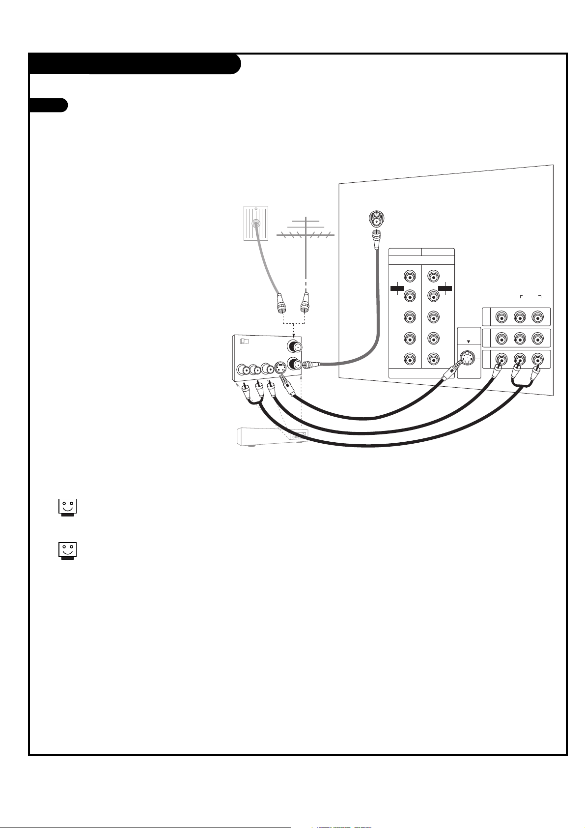
VCR Connections
1
Locate the Cable jack on the back
of your TV. Connect this to out
jack on the back of your VCR.
Or find the composite video and
audio jacks on the back of your
VCR, and connect them following
the instructions provided with
your equipment.
You may connect either the composite video or the S-Video cables
to your TV. (Do not connect BOTH
the composite and the S- Video
cables. In the event that you connect both composite and the SVideo cables, only the S-Video will
work.)
To hear stereo sound from cable or your VCR,
you will need to connect A/V cables as well as
the wire that runs from the VCR to your TV.
If you want to receive your signals on Channel
3 or 4, locate the Out to TV jack on your VCR.
Connect a cable from the Out to TV jack to the
Antenna jack on the back of your TV.
In
Out
Audio
L
R
Video
3 4
S-Video
Output
Switch
DVD/DTV INPUT
VIDEO
AUDIO
L(MONO) R
ANTENNA
PR
COMPONENT1
(480i/480p/720p/1080i)
COMPONENT2
PB
Y
L
R
IN1
IN2
AUDIO
P
R
PB
Y
L
R
AUDIO
+75 Ω
S-VIDEO
INPUT
IN3
RF coaxial wire
(75 ohm)
A/V cables
not included
with TV
or
VCR
Back AV panel
Cable TV Wall
jack panel
Antenna
Round wire
(75 ohm)

PAGE 12
DVD Player
Mini glossary
COMPONENT VIDEO Some video equipment uses three separate lines (Y, P
B, PR) to more precisely reproduce images. Your manual will explain how
this relates to your equipment.
1
2
Component input jacks
on the TV
Y
PB
PR
Video output jacks
of DVD player
Y
Y
Y
Y
Pb
B-Y
Cb
PB
Pr
R-Y
Cr
P
R
• Component Input ports
You can get better picture quality if you
connect a DVD player using the component
input ports as shown below.
A/V cables
not included
with TV
DVD player
Back AV panel
or
Back AV panel
Find the component or S-Video
jacks for video connections,
depending on your DVD connectors. Then make the corresponding audio connections. See the
diagram for either set up.
You may connect either the
composite video or the S-Video
cables to your TV. Do not connect both the composite and
the S-Video.
Some high-end DVD players use
a picture reproduction system
called “component video.” If
your DVD player has component
output, use the connectors
marked “Component 1 or 2” on
the jack panel. Please refer to
your DVD manual for proper
installation.
DVD/DTV INPUT
PR
COMPONENT1
(480i/480p/720p/1080i)
COMPONENT2
PB
Y
L
R
AUDIO
P
R
PB
Y
L
R
AUDIO
Audio
L R
Digital Audio
Optical
Component Video
CALIBRATION
DIGITAL
AUDIO OUTPUT
OPTICAL
ANTENNA
HDMI/DVI
DIGITAL
AUDIO INPUT
OPTICAL
(DVI)
+75 Ω
DVD player
A/V cables
not included
with TV
CALIBRATION
DIGITAL
AUDIO OUTPUT
OPTICAL
DIGITAL
AUDIO INPUT
OPTICAL
(DVI)
HDMI/DVI
ANTENNA
+75 Ω
COMPONENT1
COMPONENT2
(480i/480p/720p/1080i)
R
AUDIO
L
R
P
PB
Y
DVD/DTV INPUT
AUDIO
Audio
L R
S-Video
R
L
PR
S-VIDEO
B
P
INPUT
Y
AUDIO
L(MONO) R
VIDEO
IN3
IN2
IN1
PAGE 13
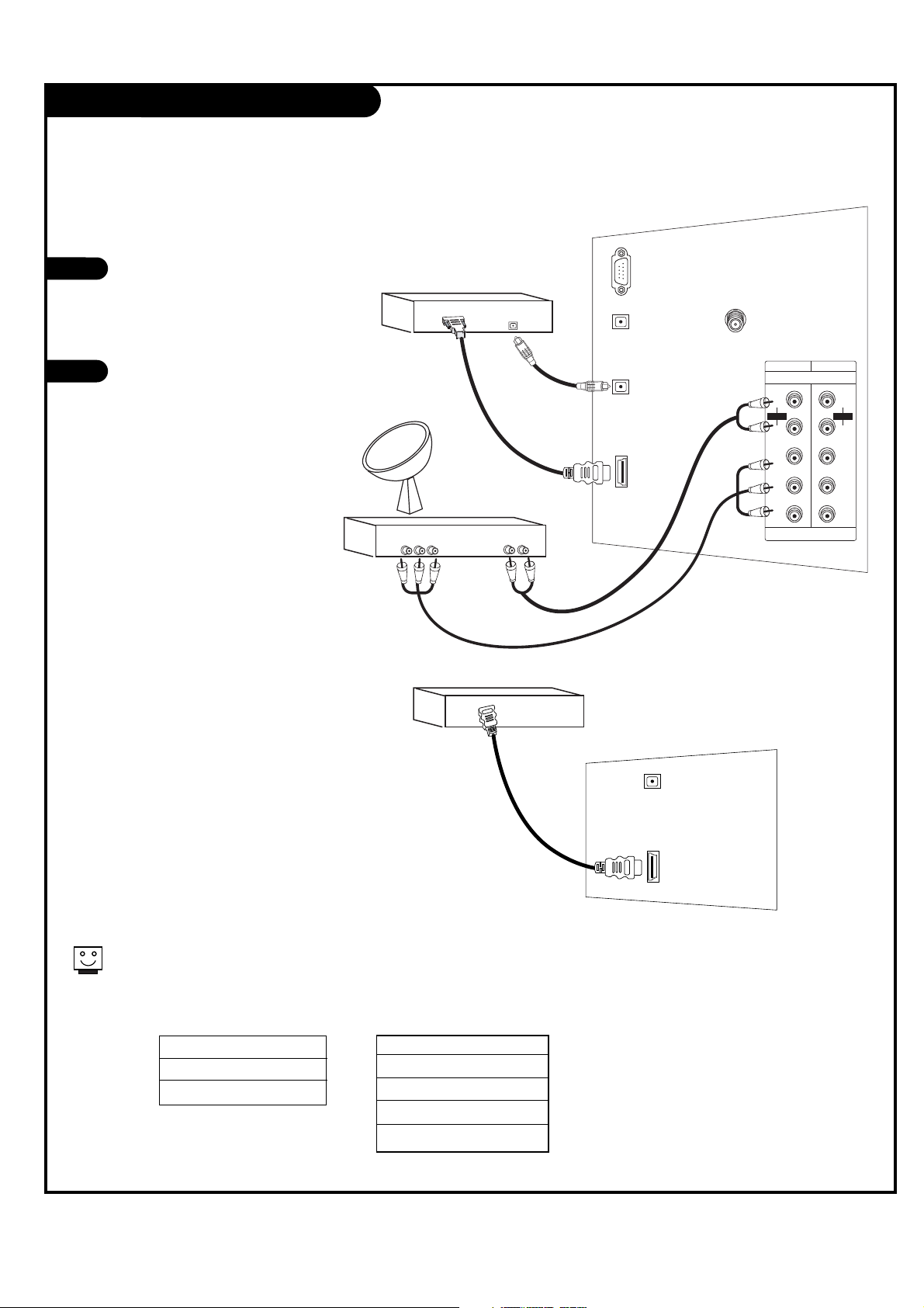
Set-top box Hookup
Find the audio and Y, PB, PR jacks or
HDMI/DVI output port on the back of
your set-top box and connect them following the instructions provided with
your equipment.
Connect these cables to your TV as
shown.
1
2
Set-top Box
Set-top Box
The DTV shows the sharpest picture in 720p/1080i mode.
1920x1080i
1280x720p
720x480p
HDMI/DVI
or
Component 1 (or 2) Input
Y PB PR
1920X1080i
1280X720p
720X480p
720X480i
or
HDMI/DVI
DIGITAL
AUDIO INPUT
OPTICAL
(DVI)
Set-top Box
Component Out
Y Pb Pr
Digital Audio
Optical Output
Audio
L R
CALIBRATION
DIGITAL
AUDIO OUTPUT
OPTICAL
DIGITAL
AUDIO INPUT
OPTICAL
(DVI)
HDMI/DVI
ANTENNA
+75 Ω
COMPONENT1
COMPONENT2
(480i/480p/720p/1080i)
R
AUDIO
L
R
P
PB
Y
DVD/DTV INPUT
R
AUDIO
L
PR
PB
Y

PAGE 14
Digital Audio Output
Connect one end of an optical cable to
the TV Digital Audio Optical Output port.
Connect the other end of the optical cable
to the digital audio optical input on the
audio equipment.
See the external audio equipment instruction manual for operation.
1
2
Send the TV’s audio out to external audio equipment (stereo system) via
the Digital Audio Output Optical port.
Caution: Do not look into the optical output
port. Looking at the laser beam may damage
your vision.
Digital Audio
Equipment
CALIBRATION
DIGITAL
AUDIO OUTPUT
OPTICAL
DIGITAL
AUDIO INPUT
OPTICAL
(DVI)
HDMI/DVI
Digital Audio
Optical Input
ANTENNA
+75 Ω
PAGE 15
HDMI
- HDMITM, the HDMI logo and High-Definition Multimedia Interface are trademarks or registered trademarks of HDMI Licensing LLC."
- This DTV can receive the High-Definition Multimedia Interface(HDMI) or Input of Digital Visual Interface(DVI).
- This DTV supports HDCP(High-bandwidth Digital Contents Protection) Protocol for DTV(480p, 720p, 1080i) modes.
- When you Connect with HDMI Source Devices (DVD Player or Set Top Box) supporting Auto HDMI function, automatically, support Plug & Play
and then set the HDMI Source Devices(1920 x 1080i). After reading in HDMI Source Devices using Display Data Channel(DDC) Protocol, EDID
stored in DTV is used. If HDMI Source Devices not supported Auto HDMI/DVI is been, the Resolution is setted, manually.
- To get the best picture quality, adjust the DVD Player or Set Top Box output resolution to 1920 x 1080i.
- When Source Devices have DVI Output Connector, you must connect audio with separated cable. (Refer to <How to connect>)
- The HDMI is not supported in 480i source.
How to connect
1. When Source Devices(DVD Player or Set Top Box) support HDMI.
- If Source Devices have HDMI Output Connector, Source Devices connect to DTV with HDMI Cable .(not supplied with the product).
- If Source Devices support Auto HDMI, automatically, Source Devices divert output resolution in 1920 x 1080i. But if not, resolution divert
Manually Setting for reference Manual of Source Devices.
- To get the best picture quality, adjust the DVD Player or Set Top Box output resolution to 1920 x 1080i.
- Because HDMI sends Digital Video and Audio with one cable, need not especial Audio Cable for using HDMI Cable.
2. When Source Devices(DVD Player or Set Top Box) supports DVI.
- If Source Devices have DVI Output Connector, Source Devices connect to DTV with HDMI to DVI Cable (not supplied with the product).
- If Source Devices support Auto DVI, automatically, Source Devices divert output resolution in 1920 x 1080i. But if not, resolution divert
Manually Setting for reference Manual of Source Devices.
- To get the best picture quality, adjust the DVD Player or Set Top Box output resolution to 1920 x 1080i.
- In this case, Audio use other cable. When Source Devices have Fiber Optic Digital Audio Output Connector, Digital Audio DVI Input(DVI) of
DTV connect to Fiber Optic Digital Audio Cable (not supplied with the product) or when Source Devices have Analog Audio Output Connector,
RGB/DVI Audio Input of DTV connect to Audio Cable (not supplied with the product). And then you can listen to normal Audio.
How to use
1. Connect the HDMI Source Devices (DVD Player or Set Top Box) and the TV set.
2. Turn on the display by pressing the ON/OFF button on the TV set and HDMI Source Devices remote control.
3. Check the image on your TV set. There may be noise associated with the resolution, vertical pattern, contrast or brightness in HDMI
Source Devices. If noise is present, change the HDMI Source Devices to another resolution, change the refresh rate or adjust the brightness and contrast on the menu until the picture is clear.
Reference
Cable sample
HDMI Cable (not supplied with the product)
HDMI to DVI Cable (not supplied with the product)

PAGE 16
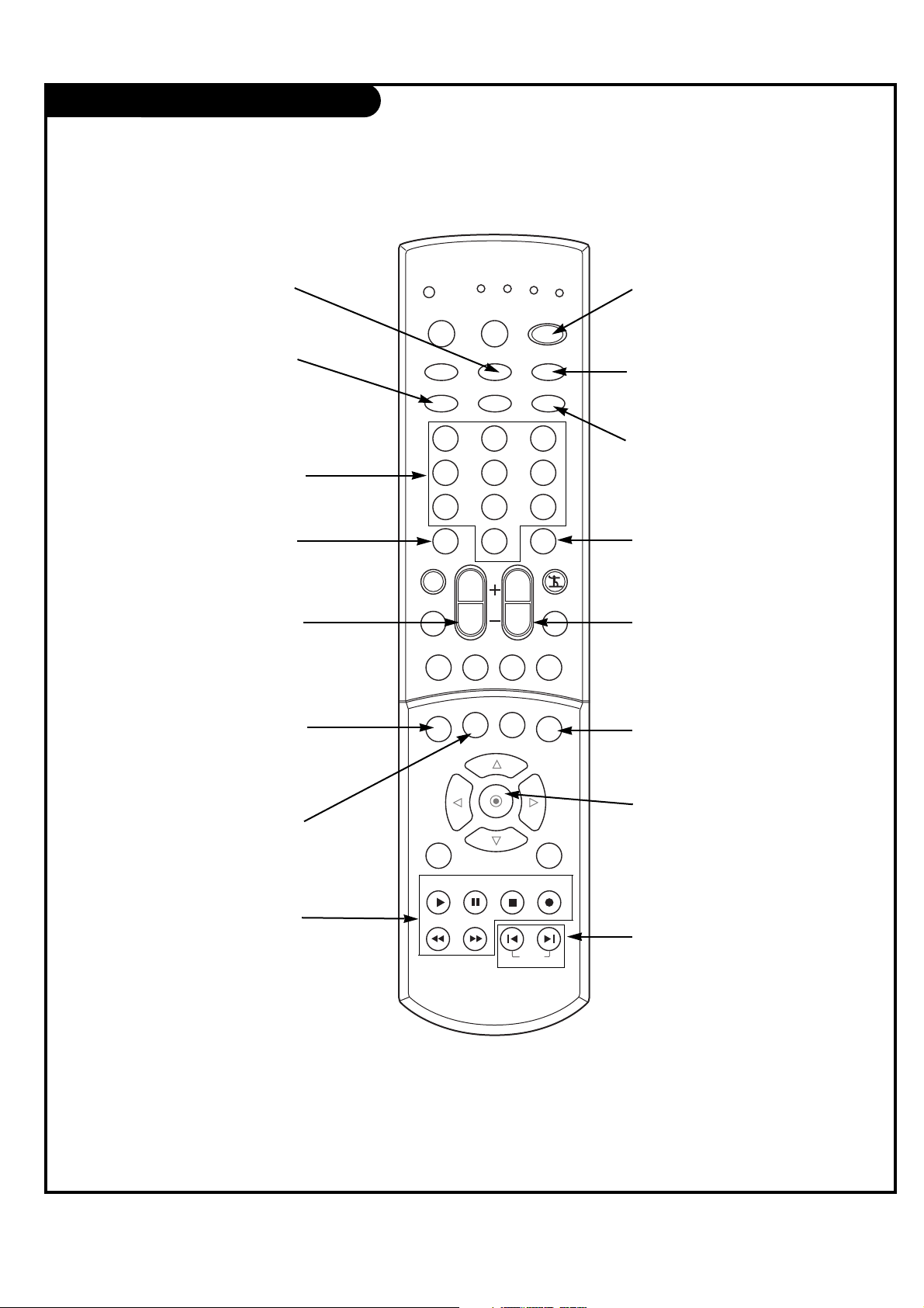
Remote Control Functions in TV Mode
FAV
Use to scroll the FAV channel
list.
MENU
Brings up the main menu
to the screen.
EXIT
Clears all on-screen displays
and returns to TV viewing
from any menu.
CC
Lets you select a closed caption
mode for displaying captioning
information when provided for
DTV/Analog signal.
EZ PIC
Adjusts the factory preset picture depending
on the viewing environment.
SAP
Selects MTS sound: Mono, Stereo,
and SAP in analog mode.
Change the audio language in
DTV mode.
SURROUND
Selects : Off, 3D EchoSound
System and SRS TruSurround
XT.
MUTE
Switches the Mute or the EZ mute.
Mute: The sound is off. EZ mute: Turns
the sound off, and displays the caption.
THUMBSTICK
(UP/DOWN/LEFT/RIGHT/ )
Allows you to navigate the on-screen menus
and to adjust the system settings and prefer-
ences, by moving to an option with
F G
and
selecting the highlighted option with .
VIDEO1
Selects the Video1 input source.
MODE
Selects the remote operating mode:
TV, VCR, Cable, DVD or Satellite.
Select other operating modes, for
the remote to operate external
devices.
COMP2
Selects the Component 2 input
source.
EZ SOUND
Selects the sound appropriate
for the program’s category.
FREEZE
Captures and freezes
the currently-viewed
picture.
RATIO
Changes the aspect ratio.
TV/VIDEO
Selects: Antenna, Cable, Video1,
Video2, Front video, Component 1-2
and HDMI/DVI input sources.
MODE INDICATOR
LIGHTS
Show active remote mode
every time any button is
pressed.
D
E
CABLE
TV
MODE
VIDEO1
VCR
TV/VIDEO
VIDEO2
COMP2COMP1
DVD
1 2 3
4 5 6
7 8 9
DASH(-)
MUTE
EZ SOUND
RATIO
INFO
MENU EXIT
PLAY
REW
0
VOL
TIMER CC
PAUSE
STOP
FF
CH
SURROUNDFREEZE SAP
SAT
POWER
FRONT
HDMI
FLASHBK
FAV
EZ PIC
SIGNAL
RECORD
SKIP
PAGE 17
Remote Control Functions in TV Mode
POWER
Turns your TV or any other
programmed equipment on or
off, depending on mode.
CHANNEL UP/DOWN
Scrolls through available channels
present in EZ Scan memory.
NUMBER KEYPAD
For direct channel selection and
programming functions.
ENTER
When in the menu system and
other on-screen displays,
selects highlighted options.
RECORD, PAUSE, REW, FFWD,
PLAY, STOP
Control the functions on your VCR.
VOLUME UP/DOWN
Increases/decreases the sound level.
INFO
When you watch the TV, dis-
plays information on top of the
screen. Not available in
Component 1-2 and HDMI/DVI.
SKIP LEFT/RIGHT
Playing CDs: Selects songs.
Playing DVDs: Selects movie
chapters.
COMP1
Selects the Component 1 input
source.
HDMI
Selects the HDMI input source.
DASH(-)
Is used to enter a program num-
ber for multiple program channels
such as 2-1,2-2,etc.
FLASHBK
Tunes to the previous channel
viewed.
TIMER
Lets you select the amount of
time before your TV turns
itself off automatically.
SIGNAL
Displays the digital signal
strength.
FRONT
Selects the front video input source.
VIDEO2
Selects the Video2 input source.
TV
VCR
CABLE
DVD
SAT
MODE
TV/VIDEO
VIDEO1
VIDEO2
COMP2COMP1
1 2 3
4 5 6
7 8 9
DASH(-)
MUTE
EZ SOUND
RATIO
INFO
MENU EXIT
PLAY
0
VOL
TIMER CC
PAUSE
STOP
CH
SURROUNDFREEZE SAP
POWER
FRONT
HDMI
FLASHBK
FAV
EZ PIC
SIGNAL
RECORD
REW
FF
SKIP
PAGE 18
Turning the TV On
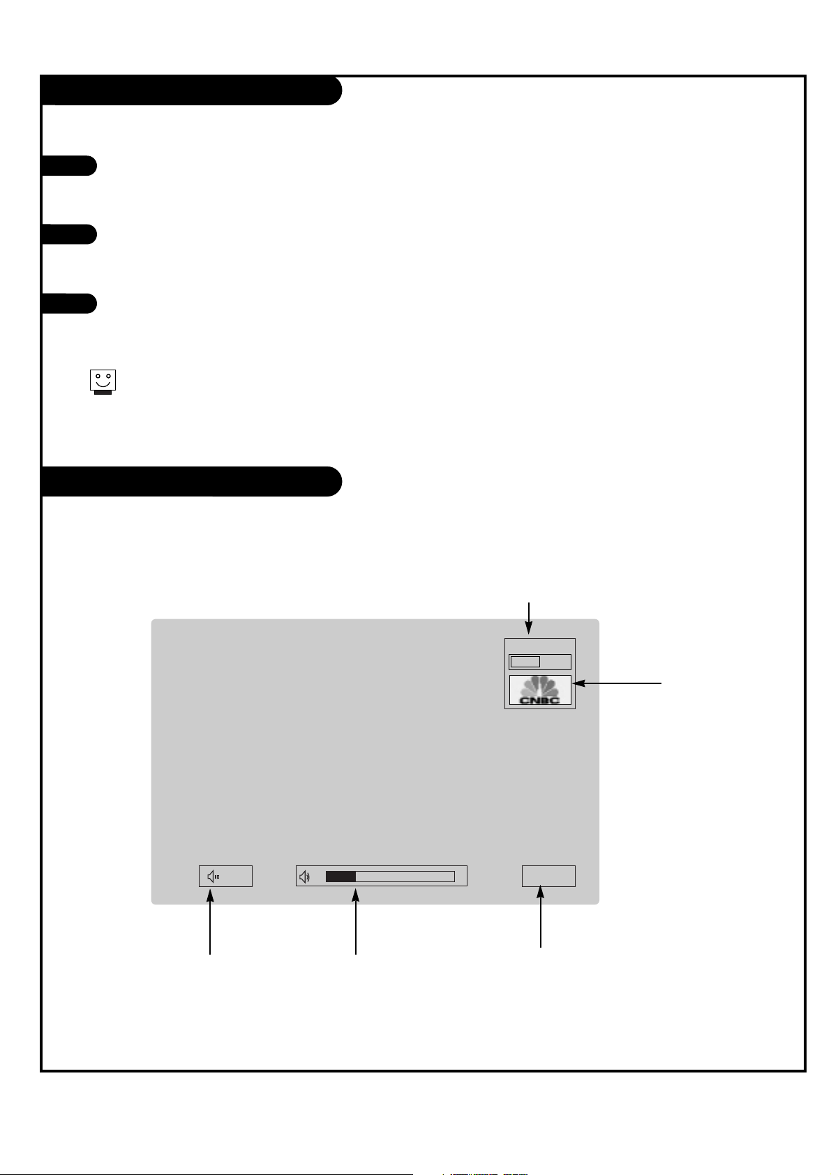
On-Screen Displays
This page describes your on-screen display and information banner options.
10
Mute
TV 2-0
MONO
10:00 AM
First, connect antenna cable and power cord correctly. At this moment, the TV switches to standby mode.
In standby mode to turn TV on, press the POWER, CH +/-, TV/VIDEO, FRONT or number buttons on the
remote control or TV/VIDEO or CH
D/E
on the TV.
Select the viewing source by using TV/VIDEO, COMP, FRONT or HDMI button on the remote control.
This TV is programmed to remember which mode it was last set to, even if you turn the TV off.
Note: See page 19 if you have not auto programmed the TV to receive channels in your local broadcast area.
When finished using the TV, press the POWER button on the remote control. The TV reverts to standby mode.
1
2
3
If you will be away on vacation, disconnect the power plug from the wall power outlet.
Volume
Volume level is displayed
while adjusting the sound.
Mute
Appears when
sound is muted.
Time
Appears when pressing the
enter button on remote control.
Channel Display
Displays current channel number.
Channel Label
Displays current
channel label.
 Loading...