

LG 32FS4D, 32FS4D-TE Service Manual

COLOR TV
SERVICE MANUAL
CAUTION
BEFORE SERVICING THE CHASSIS,
READ THE SAFETY PRECAUTIONS IN THIS MANUAL.
CHASSIS : CD61A
MODEL : 32FS4D
MODEL :
32FS4D-TE
website:http://biz.LGservice.com
e-mail:http://www.LGEservice.com/techsup.html

- 2 -
CONTENTS
CONTENTS .............................................................................................. 2
SAFETY PRECAUTIONS ..........................................................................3
CONTROL DESCRIPTIONS .................................................................... 4
SPECIFICATIONS .................................................................................... 7
ADJUSTMENT INSTRUCTIONS ............................................................. 8
TROUBLE SHOOTING .......................................................................... 17
PRINTED CIRCUIT BOARD ....................................................................20
BLOCK DIAGRAM ..................................................................................27
EXPLODED VIEW ...................................................................................28
EXPLODED VIEW PARTS LIST ..............................................................29
REPLACEMENT PARTS LIST ................................................................30
SVC. Sheet ..................................................................................................

- 3 -
SAFETY PRECAUTIONS
Many electrical and mechanical parts in this chassis have special safety-related characteristics. These parts are identified by in
the Schematic Diagram and Replacement Parts List.
It is essential that these special safety parts should be replaced with the same components as recommended in this manual to
prevent X-RADIATION, Shock, Fire, or other Hazards.
Do not modify the original design without permission of manufacturer.
General Guidance
An Isolation Transformer should always be used during
the servicing of a receiver whose chassis is not isolated from
the AC power line. Use a transformer of adequate power rating
as this protects the technician from accidents resulting in
personal injury from electrical shocks.
It will also protect the receiver and it's components from being
damaged by accidental shorts of the circuitry that may be
inadvertently introduced during the service operation.
If any fuse (or Fusible Resistor) in this TV receiver is blown,
replace it with the specified.
When replacing a high wattage resistor (Oxide Metal Film
Resistor, over 1W), keep the resistor 10mm away from PCB.
Keep wires away from high voltage or high temperature parts.
Due to high vacuum and large surface area of picture tube,
extreme care should be used in handling the Picture Tube.
Do not lift the Picture tube by it's Neck.
X-RAY Radiation
Warning:
To determine the presence of high voltage, use an accurate
high impedance HV meter.
Adjust brightness, color, contrast controls to minimum.
Measure the high voltage.
The meter reading should indicate
23.5 ± 1.5KV: 14-19 inch, 26 ± 1.5KV: 19-21 inch,
29.0 ± 1.5KV: 25-29 inch, 30.0 ± 1.5KV: 32 inch
If the meter indication is out of tolerance, immediate service
and correction is required to prevent the possibility of
premature component failure.
Before returning the receiver to the customer,
always perform an AC leakage current check on the
exposed metallic parts of the cabinet, such as antennas,
terminals, etc., to be sure the set is safe to operate without
damage of electrical shock.
Leakage Current Cold Check(Antenna Cold Check)
With the instrument AC plug removed from AC source,
connect an electrical jumper across the two AC plug prongs.
Place the AC switch in the on position, connect one lead of
ohm-meter to the AC plug prongs tied together and touch other
ohm-meter lead in turn to each exposed metallic parts such as
antenna terminals, phone jacks, etc.
If the exposed metallic part has a return path to the chassis, the
measured resistance should be between 1MΩ and 5.2MΩ.
When the exposed metal has no return path to the chassis the
reading must be infinite.
An other abnormality exists that must be corrected before the
receiver is returned to the customer.
Leakage Current Hot Check (See below Figure)
Plug the AC cord directly into the AC outlet.
Do not use a line Isolation Transformer during this check.
Connect 1.5K/10watt resistor in parallel with a 0.15uF capacitor
between a known good earth ground (Water Pipe, Conduit, etc.)
and the exposed metallic parts.
Measure the AC voltage across the resistor using AC
voltmeter with 1000 ohms/volt or more sensitivity.
Reverse plug the AC cord into the AC outlet and repeat AC
voltage measurements for each exposed metallic part. Any
voltage measured must not exceed 0.75 volt RMS which is
corresponds to 0.5mA.
In case any measurement is out of the limits specified, there is
possibility of shock hazard and the set must be checked and
repaired before it is returned to the customer.
Leakage Current Hot Check circuit
The source of X-RAY RADIATION in this TV receiver is the
High Voltage Section and the Picture Tube.
For continued X-RAY RADIATION protection, the
replacement tube must be the same type tube as specified in
the Replacement Parts List.
1.5 Kohm/10W
To Instrument’s
exposed
METALLIC PARTS
Good Earth Ground
such as WATER PIPE,
CONDUIT etc.
AC Volt-meter
IMPORTANT SAFETY NOTICE
0.15uF
OK
TVD/A
INPUT
DVD
ARC
EXIT
VOL
TEXT
UPDATE
INDEX
HOLD
SIZE
TIME
REVEAL
MIX
Q.VIEW
MUTE
PR
FAV
LIST
I/II
MENU
SLEEP
GUIDE
MULTI
INFO
VCR
POWER
123
456
789
0
SSM
PSM
?
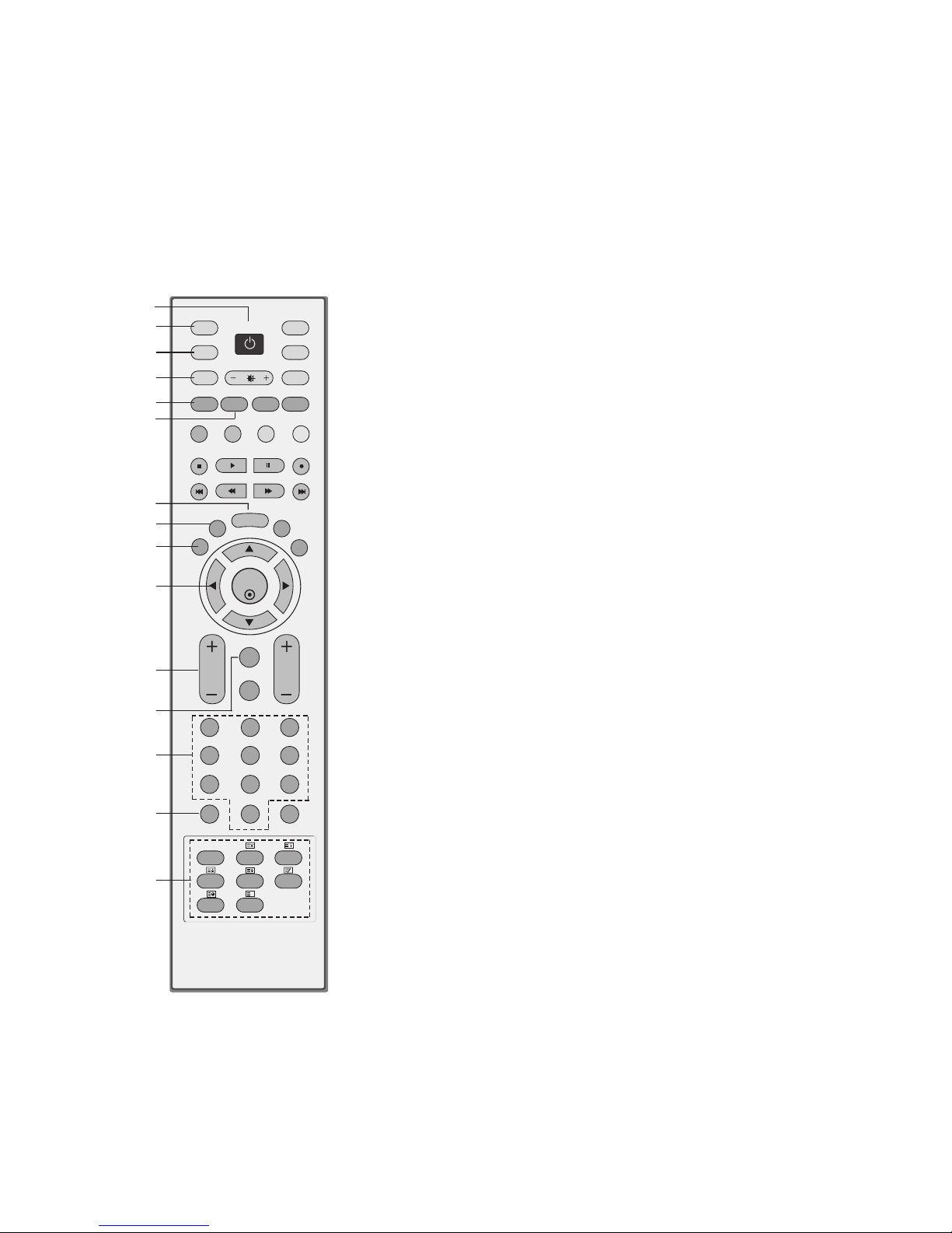
All the functions can be controlled with the remote control handset. Some functions can also be adjusted with the buttons on the
front panel of the set.
Remote control handset
Before you use the remote control handset, please install the batteries. See the next page.
1. POWER
Switches the set on from standby or off to standby.
2. D/A (Digital TV / Analogue TV)
Selects digital or analogue mode.
Switches the set on from standby.
3. INPUT
External input modes rotate in regular sequence: Digital,
Analogue, AV1-3, Component 1-2, HDMI/DVI.
Switches the set on from standby.
4. ARC (Aspect Ratio Control)
Selects your desired picture format.
5. SLEEP
Sets the sleep timer.
6. GUIDE
Shows a programme schedule.
7. MENU
Selects a menu.
8. LIST
Displays the programme table.
9. EXIT
Clears all on-screen displays and returns to TV viewing from
any menu.
10. OK
Accepts your selection or displays the current mode.
DD / EE
or
FF / GG
Adjusts menu settings.
Selects menu item.
11. VOL +/- (Volume Up/Down)
Increases/decreases sound level.
12. Q.VIEW
Returns to the previously viewed programme.
13. NUMBER BUTTONS
Switches the set on from standby or directly select a number.
14. PSM (Picture Status Memory)
Recalls your preferred picture setting.
15. TELETEXT BUTTONS
These buttons are used for teletext.
For further details, see the ‘Teletext’ section.
Text button is used to enable teletext services while other buttons are for teletext functions.
2
3
4
5
8
10
11
13
14
15
12
9
1
6
7
- 4 -
CONTROL DESCRIPTIONS
- 5 -
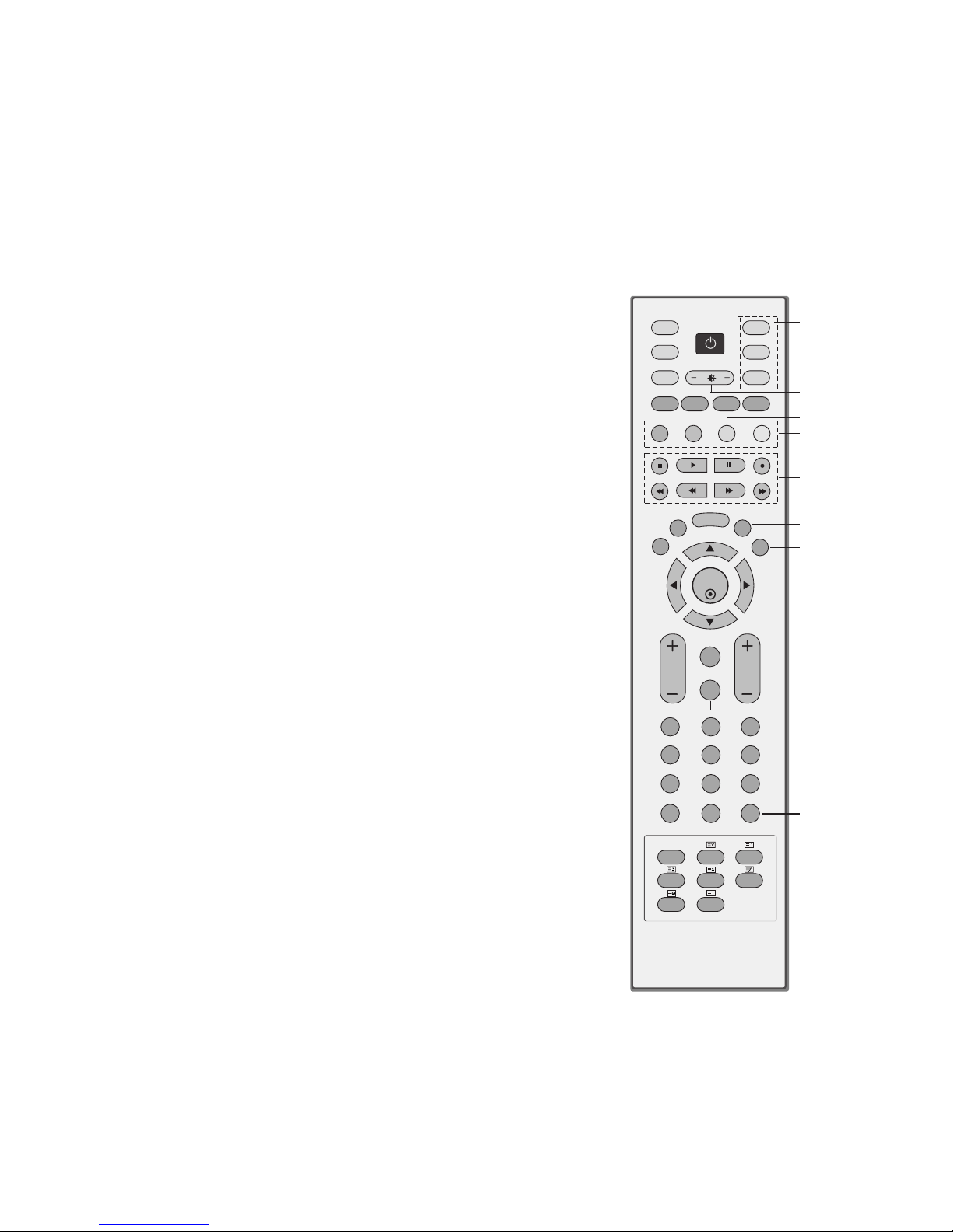
16. TV, DVD, VCR
Selects the remote operating mode: TV, VCR, DVD. Select other
operating modes, for the remote to operate external devices.
17. +/-
Adjusts brightness on screen.
It returns to the default settings brightness by changing mode source.
18. INFO
Shows the present screen information.
19. MULTI
Selects the Component 1-2 or HDMI/DVI modes.
20. COLOURED BUTTONS
They are used as per the indications or functions displayed on
the TV screen in the case of Text displays (Teletext, EPG) and
programme edit.
21. VCR/DVD control buttons
Control some video cassette recorders or DVD players
("RECORD" button is not available for DVD player).
22. I/II
Selects the language during dual language broadcast.
Selects the sound output or the audio mode.
23. FAV (FAVOURITE)
Displays the selected favourite programmes.
24. PR +/- (Programme Up/Down)
Selects a programme.
Switches the set on from standby.
25. MUTE
Switches the sound on or off.
26. SSM (Sound Status Memory)
Recalls your preferred sound setting.
OK
TVD/A
INPUT
DVD
ARC
EXIT
VOL
TEXT
UPDATE
INDEX
HOLD
SIZE
TIME
REVEAL
MIX
Q.VIEW
MUTE
PR
FAV
LIST
I/II
MENU
SLEEP
GUIDE
MULTI
INFO
VCR
POWER
123
456
789
0
SSM
PSM
?
16
17
19
18
20
21
23
24
26
25
22
- 6 -
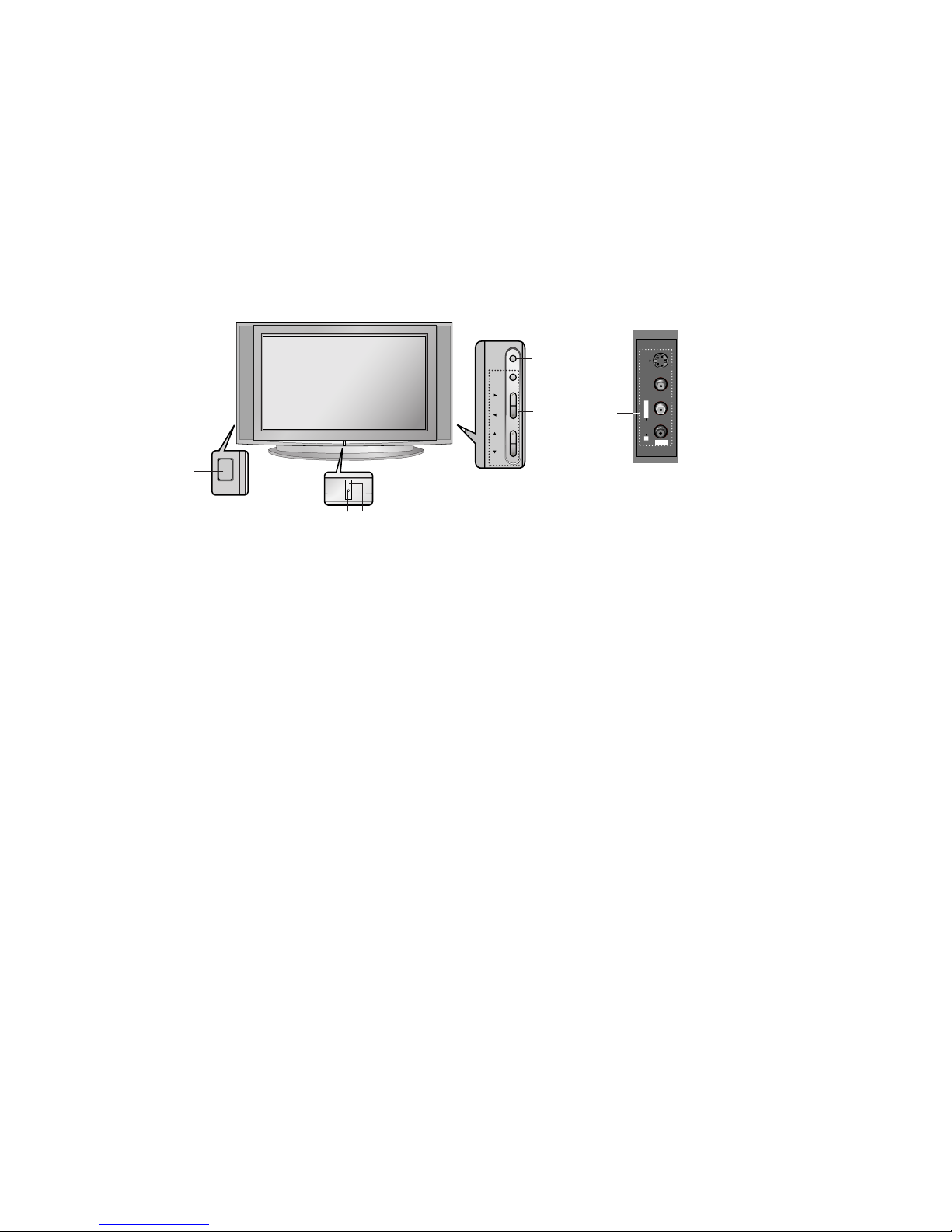
1. MAIN POWER (ON/OFF)
Switches the set on or off.
2. POWER/STANDBY INDICATOR
illuminates brightly when the set is in standby
mode.
Dims when the set is switched on.
3. MENU
Selects a menu.
4. OK
Accepts your selection or displays the current
mode.
FF / GG
(Volume Down/Up)
Adjusts the volume.
Adjusts menu settings.
DD / EE
(Programme Up/Down)
Selects a programme or a menu item.
Switches the set on from standby.
5. REMOTE CONTROL SENSOR
6. AUDIO/VIDEO IN SOCKETS (AV IN3)
Connect the audio/video out sockets of external equipment to these sockets.
S-VIDEO/AUDIO IN SOCKETS (S-AV)
Connect the video out socket of an S-VIDEO
VCR to the S-VIDEO socket.
Connect the audio out sockets of the SVIDEO VCR to the audio sockets as in AV
IN3.
Front panel
ON/OFF
MENU
OK
VOL
PR
1
Side panel
S-VIDEO
VIDEO
L/MONO RAUDIO
AV IN3
6
2
5
3
4
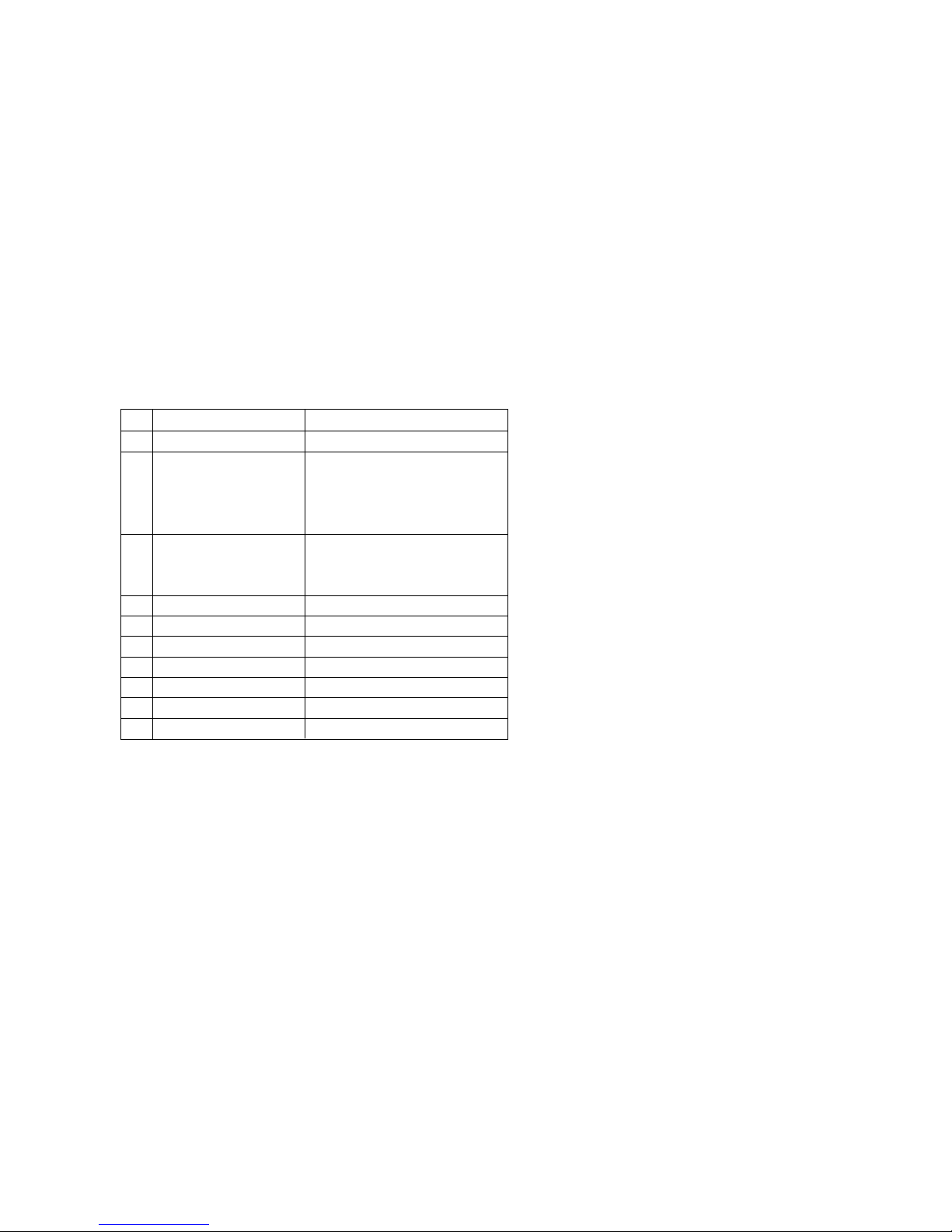
SPECIFICATIONS
Note : Specification and others are subject to change without notice for improvement.
Item
Broadcasting system
Available Channel
Tune IF
Input Voltage
Display Method
Aspect ratio
Operating Temperature
Operating Humidity
Storage Temperature
Storage Humidity
- 7 -
A Scope
This specification can be applied to all the television related to
CD61 Chassis.
A Test and Inspection Method
1) Performance : Follow the Standard of LG TV test
2) Demanded other specification
- Safety: IEC60065, EN60065
- EMC: CISPR 13 Class B
A Test Condition
1) Temperature : 25 ± 5°C (77 ± 9°C)
2) Relative Humidity : 65 ± 10%
3) Power voltage : Standard input voltage(240V~±10%, 50Hz)
* Standard voltage of each product is marked by model.
4) Follow each drawing or spec for spec and performance of
parts,based upon P/N of B.O.M
5) The receiver must be operated for about 20 minutes prior to
the adjustment.
A General Specifications
No.
1
2
3
4
5
6
7
8
9
10
Specification
PAL-B/G, DTV : DVB-T
1) VHF : 01 ~ 12
2) UHF : 20 ~ 75
3) CATV : 02 ~ 44
4) DTV : 06 ~ 12, 7 ~ 69
1) PAL : 38.90MHz(picture)
34.40MHz(sound)
2) DVB-T : 36.125MHz
240V~, 50Hz
CRT
16 : 9(wide)
1) Temp : 0 ~ 45 deg
2) Humidity: ~ 85%
1) Temp : -20 ~ 60 deg
2) Humidity: ~85%
- 8 -
ADJUSTMENT INSTRUCTIONS
1. Application Object
These instructions are applied to the CD61A chassis.
2. Notes
(1) Because this is not a hot chassis, it is not necessary to use
an isolation transformer. However, the use of an isolation
transformer will help protect test instruments.
(2) Adjustments must be done in the correct order.
(3) The input voltage of the receiver must remain at
120V±10% while adjusting.
(4) The receiver must be operated for about 20 minutes prior
to the adjustment.
* Never operate the set over 10 minutes with a still picture
because it may cause screen burn.
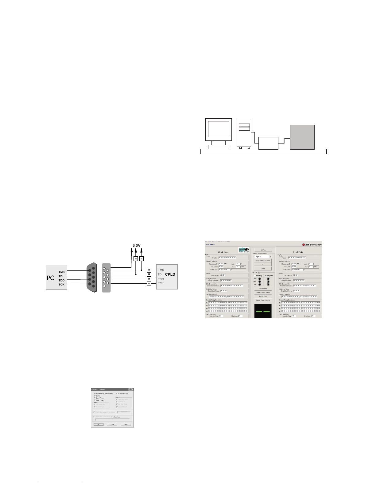
3. CPLD Download
3-1. Required Test Equipments &
Preparation for Adjustment
(1) Connect the PC and memory JIG as shown in <Fig. 1>.
(2) Turn on JIG MAIN POWER SW.
(3) Turn on the PC and monitor, operate the ‘Device
Programming’ software.
3-2. Adjustment Sequence
(1) Once the program is running, [OPTION MODE
SELECTION] is displayed in the window.
Check the “Load configuration File(.cdf, .pdr)” in this window
and click the ‘finish’ button
(2) When the screen displays the “open” window, select the
suitable file(*.cdf) according to model.
(3) IC figure is change to green by clicking it.
(4) Select program options.
(5) Check the [Erase before programming] and [Verify] menu
as shown <Fig. 2> and press the OK button.
(6) At this time, the download starts. The download will finish
in about 10 seconds.
5. EDID Data Input
5-1. Required Test Equipment
(1) PC, Jig for adjusting DDC. (256 bytes write)
(2) S/W for writing DDC(EDID data write & read)
(3) Cable for HDMI EDID Download.
5-2. Setting of Device
5-3. Adjustment
(1) Set devices as above and turn on the PC and JIG.
(2) Open S/W for writing DDC (EDID data write & read).
(3) Enter the Model-->Open in the Menu and then select EDID
DATA.
(4) Click the Digital and cancel the ANALOG.
Then connect to turn on the yellow light at the board &
connection.
(5) Click the Write Data & Verify and then download the EDID
DATA.
<Fig. 1 > How to connect the MEMORY JIG and PC
<Fig . 2>
PC
JIG
TV
SET
<Fig . 3>
<Fig . 5>

- 9 -
6. MICOM download
6-1. Required Test Equipment
(1) PC, Jig for MICOM Download
(2) S/W for MICOM Download
(3) Cable for MICOM Download.
6-2. Setting of Device
6-3. Download sequence
(1) Connect the PC Parallel Port to download JIG, and
connect the download JIG to P1700 of Board.
(2) Set PC program for JIG download as shown below.
then operate the download.
<In case of Win ISP 3.0>
(1) Configure the program for download.
1) MCU Select : MTV412M128(Use to MTV416)
2) R/W Option Auto Write(Verify)
3) Jig Option Myson
4) Transmit Speed : Medium
5) Check : blank
6) PORT “ Using Parallel Port(LPT1)
* LPT must be selected to EPP at Rom BIAS.
7) Select the Save Setting.
(2) Click the“Send” button after selecting the Load File and
Loading the Hex File.
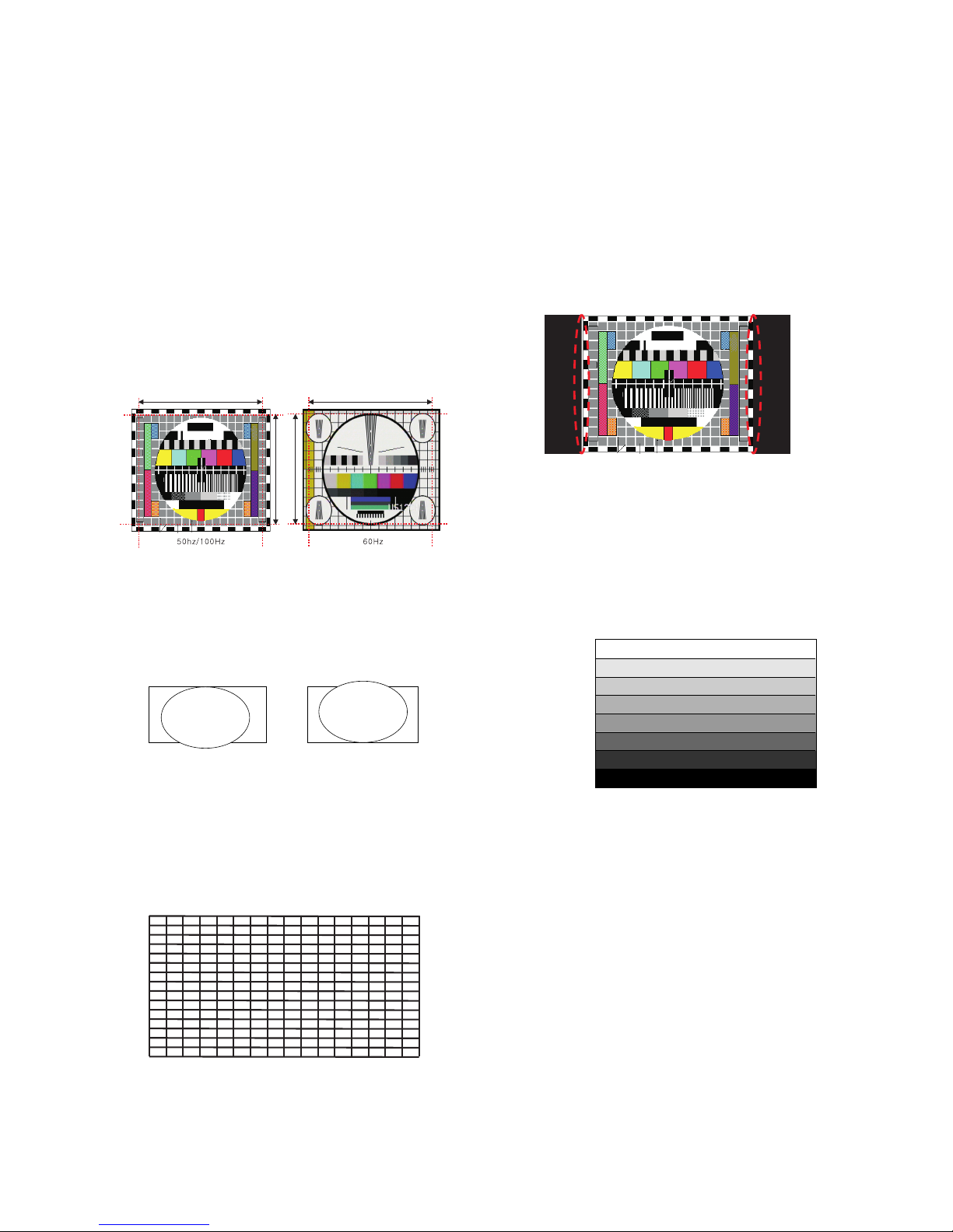
7. Focus adjustment
(1) Set the picture mode to “STANDARD”.
(2) Set the screen size to “16:9”.
(3) Receive the PAL CROSS HATCH(PAL 1-7CH) and adjust
the upper Focus volume of FBT for the best focus of
horizontal line A.
(4) Adjust the lower Focus volume of FBT for the best focus of
vertical line A.
(5) Repeat above step 1) and 2) for the best overall focus.
* This adjustment must be done after operating over 10
minutes.
8. Purity & Convergence adjustment
This adjustment should be operated when using the CPT
without ITC.
This adjustment must be done in the order of the following
flowchart.
PC
JIG
TV
SET
<Fig . 5>
<Fig . 7>
configuration of Win ISP V.3.0
Completion of Win ISP V.3.0
<Fig . 6>
Assembling DY to
CPT
CPT Assembling
As preparatory operations before
assembling CPT, wind cotton Tape for
protecting to CPT NECK and DY, CPT
connection parts. At this moment, end
of tape should be over-lapped and
wound in direct route to the NECK.
Let the screen Standard condition.
Operate Heat-Run at least 20
minutes.
Torque is to be 15-18 kg.cm when
fixing DY.
Fix the Magnet to the position as
shown picture below. Be careful not to
make CPT neck shadow while
adjusting DY.
HEAT RUN
Degaussing
STC Pre-Adjustment
PURITY Adjustment
DY Fixing
SCREEN Voltage adj.
W/B Fixing
FOCUS not yet ADJ.
STC not yet ADJ.
DYC not yet ADJ.
2–2mm
The tip of DY

8-1. PURITY adjustment
(1) It makes CPT or CABINET enough to demagnetization.
(2) Receive the signal of red raster.
(3) Loosen fixed screw of DY and closely to CPT funnel part.
(4) Check the center of screen that PURITY MAGNET of CPT
by crossing adjustment. At this time, 4 & 6 pole magnet is
located to magnet of nothing.
(5) Move the DY to make equal red on whole screen and it
does not to make the DY by fixed screw after check a
simple color of Red/Green/Blue and white raster whether
or not it is a pollution of color.
(At this time, take care raster of screen and DY must fixing
in the condition which maintains a horizontality.)
(6) Check the TV set by move direction.
9. CUT-OFF adjustment
(Screen Voltage Adjustment)
9-1. Test equipment
Oscilloscope, 100:1 Probe
9-2. Adjustment
* This adjustment must be operated only at 100Hz DISPLAY
MODE.
(1) Select EZ Adjust 3. CUT-OFF, by pressing the ADJ key on
the SVC Remote control.
When it enters to adjustment mode, the pattern from a
signal generator is being selected, it becomes with Normal
image 16:9 and the CUT-OFF DRIVE data setting 31.
(2) Connect the oscilloscope ground lead to GND on the CPT
board and the probe to the GK pin connector of the CPT
socket.
Using the SCREEN knob on the Fly Back Transformer,
adjust the black level voltage to 160±2V.
10. Deflection adjustment
10-1. 16:9 deflection adjustment
* This adjustment must be operated after changing signal
to Multi signal.
- Adjustment sequence
NTSC H,V adjustment --> HRS correction --> NTSC H,V
re-adjustment(60Hz) --> PAL H,V adjustment(100Hz) -->
PAL H,V adjustment(50Hz) --> PAL(50Hz) 4:3 adjustment
- MULTI 48ch, STANDARD, 16:9 screen is displayed when
Digital pattern is 50/100Hz or PAL B/G(EU05CH) or 60Hz
at H,V adjustment mode.
(1) 60Hz Vertical Deflection Size adjustment
1) Select “EZ Adjust 1. Raster, Cent, H/V Size(60Hz)” by
using the ADJ key on the SVC Remote control.
2) Select “V-SIZE” in the adjustment mode.
3) Adjust until the smaller inscribed circle coincides with
the outer frame of screen.
4) Select 95. LO-VLIN or 94. UP-VLIN and adjust until the
larger inscribed circle coincides with the outer frame of
screen.
(2) Raster H-center (H. CENTER) adjustment
: Select “77. H Position” in the adjustment mode and adjust
until left and right screen are symmetrically equal.
(3) Raster V-center (V. CENTER) adjustment
: Select “1. V-Position” in the adjustment mode and adjust
it to position the vertical center line in vertical center of
the CPT.
(4) Vertical Deflection Size Adjustment
1) Reduce “4. H-Size” to verify screen protection
(overscan) on the right and left sides.
2) In the adjustment mode, the third on the 48CH pattern is
to be located in the outer angle as adjusting th H-SIZE.
(5) HRS switch adjustment(only 60Hz display mode)
- 10 -
160 – 2V
<Fig . 8> CUT-OFF adjustment
<Fig . 10> CUT-OFF adjustment
A
B
Actual screen size
(a)
(b)
<Fig . 9>
A(Left) B(Right)
F
F
Right
Left
Neutrality
SW1401
<Fig . 11> MULTI CH48
L-LIN U-LIN
- 11 -
1) Initial switch(SW1401) is located in neutrality.
2) Reduce by forth~fifth of H-SIZE and then check the
things rolled the screen occurs.If not, you locate the
switch in neutrality.
If the things rolled A(the left) occurs, move SW1401 to
the right.
If the things rolled B(the right) occurs, move SW1401 to
the left.
(6) Re-adjust 60Hz H,V SIZE and POSITION after adjusting
HRS.
(7) 60Hz PINCUSION adjustment
: Adjust PIN-PHASE, PIN-AMP, AFC-BOW, AFC-ANGLE,
UP-CPIN, LO-CPIN to be straight without pin cushion
distortion and trapezoid distortion in “1.Raster,Cent,H/V
Size(60Hz)” adjustment mode.
(8) Vertical, horizontal deflection adjustment of 50, 100Hz
1) Select “2.V-SIZE” in adjustment mode.
2) As shown above <Fig. 12>(a), adjust large circle with the
dotted line of screen, though to do width dotted line size.
3) To be up and down symmetry, adjust the larger one than
outer angle of the screen with 5.LO-VLIN or 6.UP-VLIN.
(9) Raster H-center & Horizontal deflection adjustment
1) Select 3. H Position in the adjustment mode and adjust
until left and right screen are symmetrically equal.
2) With“4. H-SIZE”, adjust the screen size as shown above
dotted line rate of <Fig . 12>(a).
(10) 50, 100Hz PINCUSION adjustment
* This adjustment must be operated after changing signal
to PAL B/G or Multi signal.
1) Adjust “2.Raster, Cen, H/V Size(100Hz)” by pressing
“ADJ” button on the SVC remote control.
2) Adjust “3.Pin-Cushion(100Hz)” by pressing “ADJ” button
on the SVC remote control.
3) Adjust “4.Raster,Cent,H/V Size(50Hz)” by pressing
“ADJ” button on the SVC remote control.
4) Adjust “5.Pin-Cushion(50Hz)” by pressing “ADJ” button
on the SVC remote control.
10-2. 4:3 deflection adjustment(only 50Hz)
1) Adjust “6. 4:3 Pin-Cushion(50Hz)” by pressing “ADJ”
button on the SVC remote control.
2) Adjust the Pin-cushion data to be vertical line a left/right
line of 4:3 screen (ARC).
11. Component MST3000 Offset/Gain
Adjustment
11-1. Test Equipment
801GF(802B, 802F, 802R) Pattern Generator or MASTER
Pattern Generator
11-2. Preliminary Steps
(1) Turn the power supply on.
(2) Enter the Component 1 mode.
(3) Receive the “1080I” Format, “Hoz30Bar” Pattern of the
Video Pattern Generator.
(4) Certainly, adjust the output signal in state of 700mVp-p
±10mV.
11-3. ADC Offset Adjustment
(1) After receiving a signal press the ADJ Key on the SVC
Remote Control repeatedly to access the Adjustment
mode.
A
B
Actual screen size
(a)
(b)
<Fig . 12>
<Fig . 14>
<Fig . 13>
L-LIN
U-LIN
100% White
100% Yellow
100% Cyan
30% Gray
30% Gray
100% Red
100% Blue
Black
<Fig . 16> 1080I Format, Hoz30Bar Pattern
<Fig . 15> 1080I Format, Hoz30Bar Pattern
(2) Adjustment will set the automatically by pressing the
“8.MST3000-Set” of adjustment item.
(3) After finishing the adjustment, output the “MST3000-OK”
OSD on the screen.
12. White Balance Adjustment
(Only 100Hz Display mode)
12-1. Preparation for Adjustment
(1) Perform the Screen Voltage Adjustment first.
(2) Change the automatic image mode to “STANDARD/ W/B
MEDIUM”.
(3) Start adjustments from initial setting of R.DRIVE=31,
G.DRIVE=31, B.DRIVE=31, R.CUT=31, G.CUT=31,
B.CUT=31.
(4) For manual adjustment, refer to the following procedure.
12-2. Adjustment(manual)
(1) Receive the White Pattern.
(2) Set screen size to wide mode(16:9).
(3) Select “2.White Balance” by pressing IN-START button on
the SVC Remote control.
(4) Adjustment
1) Using the SVC Remote control, set the DCOL value of
CXA2150 to the “0”.
2) Set an image with STANDARD/ W/B MEDIUM.
3) Adjust R-DRIVE and B-DRIVE data so the color
coordinates in High light are the values in Table below.
(Bright Level : 35fl)
4) Adjust “CONTRAST” and “BRIGHT” so the bright level is
4.5±0.5F.L.
5) Adjust R-CUT and B-CUT data so the color coordinates
in Low light are the values in Table below.
6) Repeat 3)~ 5) until the color coordinates in High and
Low color satisfies the Table.
7) Check the adjusted color coordinates with the white
balance meter.
High Light : x=287
±3, y=293±3
Low Light : x=287
±3, y=293±3
Color temperature : 9,000K
±1000(-5MPCD)
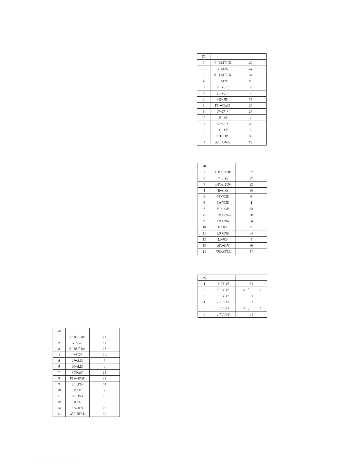
13. Service mode data 1(ADJ button)
13-1. Raster, Center, H/V_Size & 16:9 Pin-
cushion DATA
(1) 50Hz
(2) 100Hz
(3) 60Hz
13-2. W/B DATA(STANDARD)
13-3. SUB-BRIGHT
17(100Hz)/ 30(50Hz)/ 47(60Hz)
13-4. SUB-TINT/COLOR
SUB-TINT : 6
SUB-COLOR : 2
- 12 -
ITEM
DATA
ITEM
DATA
ITEM
DATA
ITEM
DATA
Fixing
Fixing

- 13 -
14. Service mode data2
(IN-START button)
14-1. CXA2150(50Hz)
R_CUTOFF
UP_CPIN
Initial data Initial data Initial data
 Loading...