

LG 29FU1RLX, 29FU1RLX-T1 Service Manual

COLOR TV
SERVICE MANUAL
CAUTION
BEFORE SERVICING THE CHASSIS,
READ THE SAFETY PRECAUTIONS IN THIS MANUAL.
CHASSIS : CW62C
MODEL : 29FU1RLX
MODEL :
29FU1RLX-T1
website:http://biz.LGservice.com
June, 2007
Printed in ChinaP/NO : MFL37794405

- 2 -
CONTENTS
Contents...................................................................................................................2
Safety Precautions..............................................................................................3
Control Descriptions..........................................................................................4
Specifications........................................................................................................7
Adjustment Instructions .................................................................................8
Trouble Shooting ................................................................................................16
Printed circuit board........................................................................................20
Block Diagram .....................................................................................................22
Exploded View....................................................................................................24
Exploded View Parts List .............................................................................25
Replacement Parts List .................................................................................26
SVC. Sheet..................................................................................................................
- 3 -
SAFETY PRECAUTIONS
Many electrical and mechanical parts in this chassis have special safety-related characteristics. These parts are identified by in
the Schematic Diagram and Replacement Parts List.
It is essential that these special safety parts should be replaced with the same components as recommended in this manual to
prevent X-RADIATION, Shock, Fire, or other Hazards.
Do not modify the original design without permission of manufacturer.
General Guidance
An isolation Transformer should always be used during
the servicing of a receiver whose chassis is not isolated from
the AC power line. Use a transformer of adequate power rating
as this protects the technician from accidents resulting in
personal injury from electrical shocks.
It will also protect the receiver and it's components from being
damaged by accidental shorts of the circuitry that may be
inadvertently introduced during the service operation.
If any fuse (or Fusible Resistor) in this TV receiver is blown,
replace it with the specified.
When replacing a high wattage resistor (Oxide Metal Film
Resistor, over 1W), keep the resistor 10mm away from PCB.
Keep wires away from high voltage or high temperature parts.
Due to high vacuum and large surface area of picture tube,
extreme care should be used in handling the Picture Tube.
Do not lift the Picture tube by it's Neck.
X-RAY Radiation
Warning:
To determine the presence of high voltage, use an accurate
high impedance HV meter.
Adjust brightness, color, contrast controls to minimum.
Measure the high voltage.
The meter reading should indicate
23.5 ± 1.5KV: 14-19 inch, 26 ± 1.5KV: 19-21 inch,
29.0 ± 1.5KV: 25-29 inch, 30.0 ± 1.5KV: 32 inch
If the meter indication is out of tolerance, immediate service
and correction is required to prevent the possibility of
premature component failure.
Before returning the receiver to the customer,
always perform an AC leakage current check on the exposed
metallic parts of the cabinet, such as antennas, terminals, etc.,
to be sure the set is safe to operate without damage of
electrical shock.
Leakage Current Cold Check(Antenna Cold Check)
With the instrument AC plug removed from AC source,
connect an electrical jumper across the two AC plug prongs.
Place the AC switch in the on position, connect one lead of
ohm-meter to the AC plug prongs tied together and touch other
ohm-meter lead in turn to each exposed metallic parts such as
antenna terminals, phone jacks, etc.
If the exposed metallic part has a return path to the chassis, the
measured resistance should be between 1MΩ and 5.2MΩ.
When the exposed metal has no return path to the chassis the
reading must be infinite.
An other abnormality exists that must be corrected before the
receiver is returned to the customer.
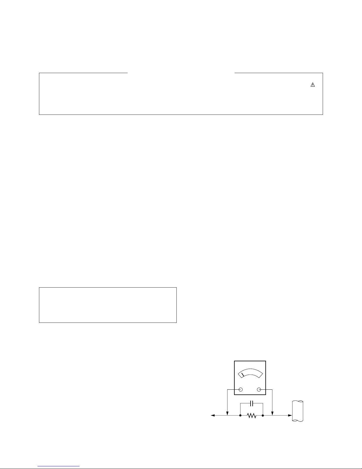
Leakage Current Hot Check (See below Figure)
Plug the AC cord directly into the AC outlet.
Do not use a line Isolation Transformer during this check.
Connect 1.5K/10watt resistor in parallel with a 0.15uF capacitor
between a known good earth ground (Water Pipe, Conduit, etc.)
and the exposed metallic parts.
Measure the AC voltage across the resistor using AC
voltmeter with 1000 ohms/volt or more sensitivity.
Reverse plug the AC cord into the AC outlet and repeat AC
voltage measurements for each exposed metallic part. Any
voltage measured must not exceed 0.75 volt RMS which is
corresponds to 0.5mA.
In case any measurement is out of the limits specified, there is
possibility of shock hazard and the set must be checked and
repaired before it is returned to the customer.
Leakage Current Hot Check circuit
The source of X-RAY RADIATION in this TV receiver is the
High Voltage Section and the Picture Tube.
For continued X-RAY RADIATION protection, the
replacement tube must be the same type tube as specified in
the Replacement Parts List.
1.5 Kohm/10W
To Instrument’s
exposed
METALLIC PARTS
Good Earth Ground
such as WATER PIPE,
CONDUIT etc.
AC Volt-meter
IMPORTANT SAFETY NOTICE
0.15uF
- 4 -
DESCRIPTION OF CONTROLS
All the functions can be controlled with the remote control handset.
Some functions can also be adjusted with the buttons on the front
panel of the set.
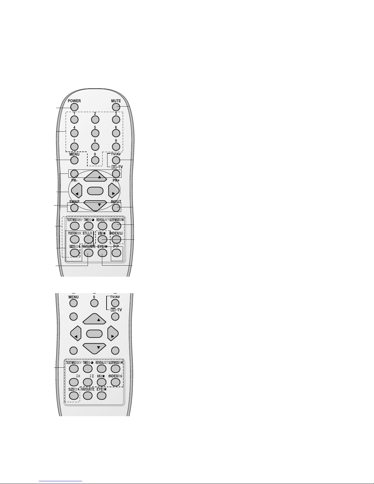
Remote control handset
Before you use the remote control handset, please install the batteries. See the next page.
1. POWER
switches the set on from standby or off to standby.
2. NUMBER BUTTONS
Switches the set on from standby or directly select a number.
3. MENU
selects a menu.
4.
D / E
(Programme Up/Down)
selects a programme or a menu item.
switches the set on from standby.
scans programmes automatically.
F / G
(Volume Up/Down)
adjusts the volume.
adjusts menu settings.
OK
accepts your selection or displays the current mode.
5. TELETEXT BUTTONS (option)
These buttons are used for teletext.
For further details, see the ‘Teletext’ section.
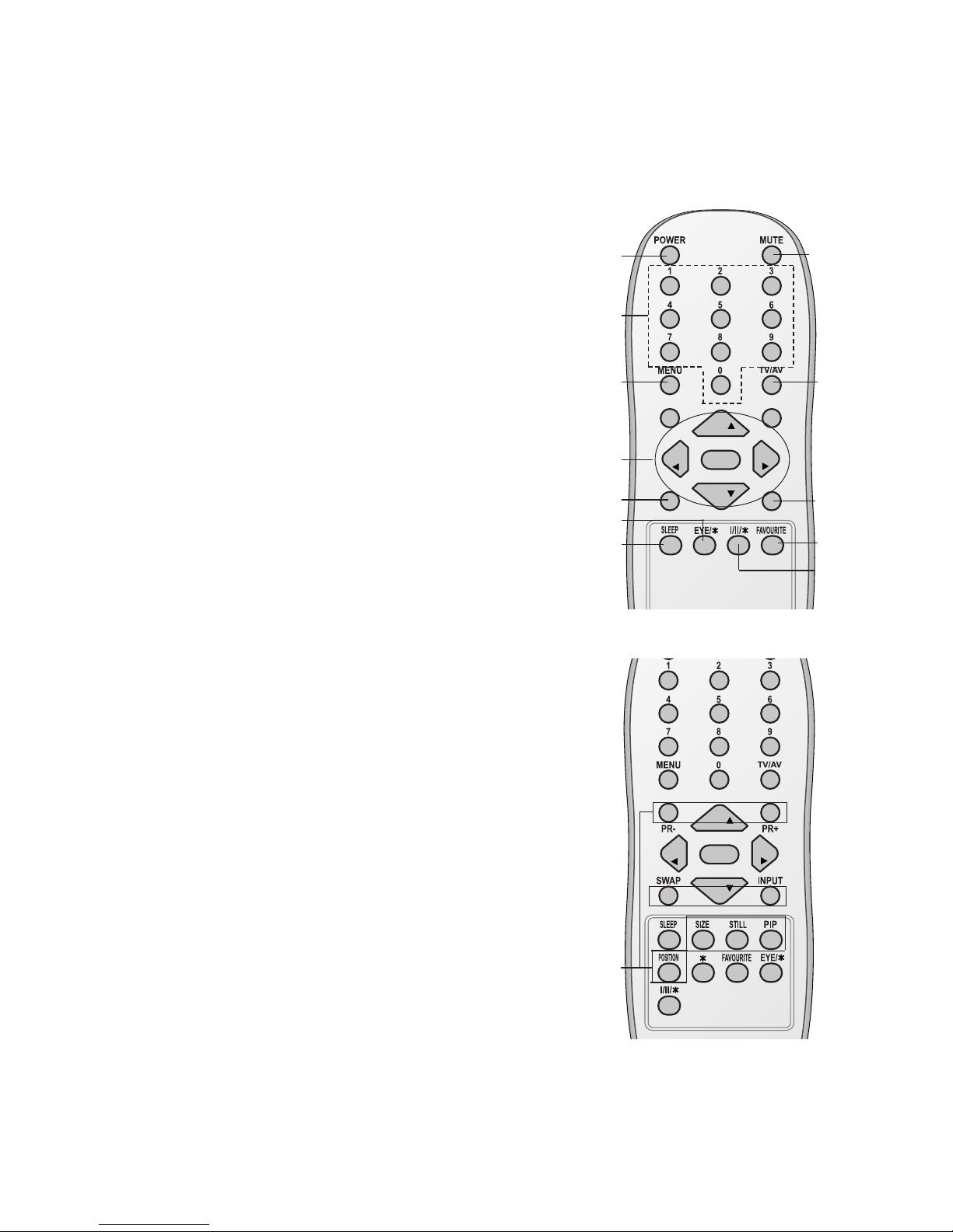
6.
SLEEP
sets the sleep timer.
7. PIP BUTTONS (option)
PIP
switches the sub picture on or off.
PR +/-
selects a programme for the sub picture.
SWAP
alternates between main and sub picture.
INPUT
selects the input mode for the sub picture.
SIZE
adjusts the sub picture size.
STILL
freezes motion of the sub picture.
POSITION
relocates the sub picture in clockwise direction.
(With TELETEXT / PIP)
PR
PR
OK
VOL
VOL
1
2
3
4
6
5
13
7
8
10
11
12
14
PR
PR
OK
VOL
VOL
Q.VIEW LIST
UPDATE/ HOLD/
(With TELETEXT / Without PIP)
5
9
- 5 -
8. FAVOURITE
selects a favorite programme.
9.
EYE/*(option)
switches the eye function on or off.
10. MUTE
switches the sound on or off.
11. TV/AV
selects TV or AV mode.
switches the set on from standby.
exits the Teletext mode.
12.
I/II/
*
selects the language during dual language broadcast.
selects the sound output (option).
13. Q.VIEW (or YELLOW)
returns to the previously viewed programme.
14.
LIST (or BLUE)
displays the programme table.
*
: No function
COLOURED BUTTONS : These buttons are used for teletext (only
TELETEXT models) or programme edit.
(Without TELETEXT / PIP)
PR
PR
OK
VOL
VOL
(With PIP / Without TELETEXT)
PR
PR
OK
VOL
VOL
Q.VIEW LIST
1
2
3
4
13
6
9
10
11
8
14
7
12
- 6 -
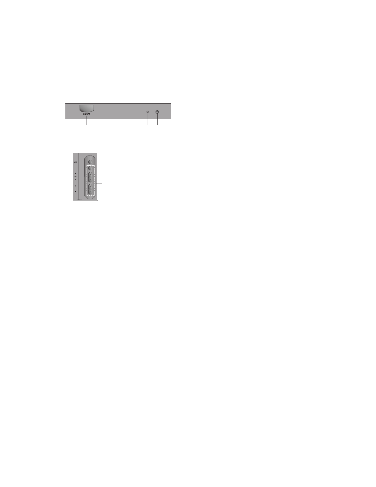
1. MAIN POWER (ON/OFF)
switches the set on or off.
2. POWER/STANDBY INDICATOR
illuminates brightly when the set is in standby
mode.
dims when the set is switched on.
3. MENU
selects a menu.
4. OK
accepts your selection or displays the current
mode.
FF / GG
(Volume Down/Up)
adjusts the volume.
adjusts menu settings.
DD / EE
(Programme Up/Down)
selects a programme or a menu item.
switches the set on from standby.
5. REMOTE CONTROL SENSOR
Note : Only use the supplied remote control
handset. (When you use others, they will not be
able to function.)
6. AUDIO/VIDEO IN SOCKETS (AV IN3)
(option)
Connect the audio/video out sockets of external
equipment to these sockets.
S-VIDEO/AUDIO IN SOCKETS (S-AV)
Connect the video out socket of an S-VIDEO
VCR to the S-VIDEO socket.
Connect the audio out sockets of the S-VIDEO
VCR to the audio sockets as in AV IN3 (option).
7. TURBO SOUND / PICTURE (option)
switches Turbo sound or Turbo picture function
on or off.
PR
OK
29FU1 series
1
4
5
2
3

- 7 -
SPECIFICATIONS
Note : Specification and others are subject to change without notice for improvement.
V Scope
This specification can be applied to all the television related to
CW62C Chassis.
V Test and Inspection Method
1) Capability: It follows the TV QC Standard of LGE.
2) Standards of Etc. requirement
- Safety: IEC60065
-EMC : CE standard(EN55020,EN55013)
V Test Condition
Conduct the test as mentioned below.
2.1 Temperature : 25 ± 5°C ( CST 40±5°C)
2.2 Relative Humidity : 65
± 10%
2.3 Power Voltage :
2.4 Follow each drawing or spec for spec and performance of
parts, based upon P/N of B.O.M.
2.5 Warm up TV set for more than 20min. before the
measurement (If no problem in capability,this allow omitted)
No
1
2
3
4
5
6
7
Item
Receiving System
Receiving Channel
Input Voltage
Market
Picture inch
Tuning System
Operating Environment
Storage Environment
Remark
Korea,Japan,Taiwan,North
America,Middle South American
EU /Non EU MODEL
OPTION
Korea,Taiwan,North America.
Middle south American
Japan
1)EU/Non EU Model
2)NTSC-M
(Multi-model NTSC-M)
Korea
Middle south America
North America
Japan
Taiwan
NON-EU
EU
NTSC MODEL
PAL MODEL
200 PR(W/O TXT )
Specification
1) NTSC M
2) NTSC M/ PAL M/N
1) PAL,SECAM BG
2) PAL/SECAM DK
3) PAL-I/I
4) NTSC M
5) NTSC 4.43(AV)
6) SECAM L/L
7) NTSC M/PAL M/N
1) VHF : 02~13
UHF : 14~69
CATV : 02~125
2) VHF/UHF : 1~62CH
CATV : C13~C38CH
TOTAL 88CH
3) VHF : E2 ~ E12
UHF : E21 ~ E69
CATV : S1 ~ S20
HYPER : S21 ~ S41
4) VHF : 02 ~ 13
UHF : 14 ~69
CATV : 02 ~ 71
AC 220V, 60Hz
AC 100 ~ 240V, 50/60Hz
AC 120V, 60Hz
AC 100V, 50/60Hz
AC 110V, 60Hz
AC 110 ~ 240 V/50Hz, 60Hz
AC 230 V 50/60 Hz
Korea, Japan, Taiwan, North
America. Middle South
American ,Filipine, China,
Middle Asia, Asia, EU, CIS
FLAT 29”
FS
FVS 100 program
1)Temp : 0 ~ 45 deg
2)Humidity : under 85 %
1)Temp : -20 ~ 60 deg
2)Humidity : under 85 %
V General Specification
Market Place
Miesast/Africa
EU/CIS
Band
LG
LG
Standard input Voltage
110 ~240 V 50/60Hz
230V 50Hz
Remark
Initial

1. Application Object
This specification can be applied to all the television related to
CW62C Chassis
2. Notes
(1) Because this is a cold chassis, it is not necessary to use
an isolation transformer. However,operating it using a
transformer between the power supply line and chassis
input to prevent electric shock and to protect the test
instrument.
(2)All adjustments must be done in correct sequence.
However, for better productivity, it can be changed in a prepermitted range.
(3) Environment conditions: If not specified, it must be done in
following conditions.
1) Temperature: 25±5°C
2) Humidity : 65±10%
(4) AC Voltage 220V ±10%
(5) If not specified, the receiver must be operated for more
than 20 minutes prior to the adjustment.
(6) Signal: Received the standard color signal. (65dB±1dBuV)
PAL/SECAM: LG standard signal means the digital
pattern PAL_EU 05CH
3. Adjust Item
3.1.1. Preparation for Adjustment.
- Receive PAL-B/G 07ch.(Cross hatch pattern) likes fig.1.
- Select the Picture mode to Standard or clear.
3.1.2. Adjustment.1
Adjust FOCUS VOLUME(the top volume of FBT)
¨and
make the FOCUS of vertical line on the quarter of
screen(red area in fig.1) achieve the best state.
3.2. Purity and Convergence adjustment
Following direction is a case using of None-ITC CPT for CPT
manufacture factory.
This adjustment should be done as below direction.
3.2.1. Purity adjustment
a. Do degauss CPT and Cabinet
b. Receive Red Raster signal. (Gumi PG50ch.)
c. Unfasten fixing Screw of DY, close DY to CPT Funnel DY
as possible as you can.
d. Make R-Land be centered as cross Purity Magnet
That time,4th 6th magnet should keep free gauss status.
e. Make uniform RED Raster as moving DY,
Check there is purity problem or not on R/G/B, white
Raster.Then, Fix screw of DY.
(At this time, be careful about inclination and DY should be
fixed keeping horizontality)
f. Check the TV in direction of EAST, WEST, SOUTH,
NORTH,. Adjust with supporting MAGNET when
adjustment is not operated ..
3.2.2. Adjustment for Convergence
This adjustment should be operated at the best condition of
FOCUS after finishing the PURITY adjustment.
1) BACK RASTER receives black CROSS HATCH signal.
2) Adjust Brightness so that there are 9-12 dots.
3) Widen two tabs of 4pole Magnet with equal angles and
accord red, blue vertical lines at the center of screen.
4) With keeping angle of "c. clause", rotate tab and accord
red/blue, green vertical lines at the center of screen.
- 8 -
ADJUSTMENT INSTRUCTIONS
A
B
<Fig 1. Cross-Hatch Pattern(NTSC:US 09CH, PAL:E-7 CH)
Integrate DY and
Magnet into CPT
CPT Assembly
As preparatory operations before
assembling CPT, wind cotton Tape for
protecting to CPT NECK and DY, CPT
connection parts. At this moment, end
of tape should be over-lapped and
wound in direct route to the NECK.
It needs minimum 15 minutes for
heat run under "standard" picture
condition.
DY FIXED Torque 9~11 kg f.cm
Fix the Magnet to the position as
shown picture below. Be careful not to
make CPT neck shadow while
adjusting DY.
HEAT RUN
Degaussing
STC Pre-Adjustment
Purity adjustment
DY Fixing
SCREEN Voltage adj.
W/B Fix
FOCUS adjustment
STC adujustment
DYC adujustment
Convergence Magnet
15 ~ 20mm
6Pole
4
2
Fig.2 Adjustment Sequence
 Loading...