

LG 29FB5RL, 29FB5RLX, 29FB5RLX-ZG service manual

更多难得资料请到江南家电维修论坛免费下载!
http://bbs.520101.com
COLOR TV
SERVICE MANUAL
CAUTION
BEFORE SERVICING THE CHASSIS,
READ THE SAFETY PRECAUTIONS IN THIS MANUAL.
CHASSIS : CW62A
MODEL : 29FB5RL/RLX
MODEL :
29FB5RL/RLX-ZG
website:http://biz.LGservice.com
e-mail:http://www.LGEservice.com/techsup.html

更多难得资料请到江南家电维修论坛免费下载!
http://bbs.520101.com
- 2 -
CONTENTS
Contents.....................................................................................................
..............2
Safety Precautions......................................................................................
........3
Control Descriptions ..........................................................................................4
Specifications ..
......................................................................................................7
A djustment Instructions .................................................................................8
Trouble Shooting ...................
.............................................................................14
Printed circuit board.......................
..................................................................18
Block Diagram ...................................
..................................................................20
Exploded View ..................................
..................................................................22
Exploded View Parts List ..................................
...........................................23
Replacement Parts List ..........................................................
.......................24
S VC. Sheet..............................................................................
....................................
更多难得资料请到江南家电维修论坛免费下载!
http://bbs.520101.com
- 3 -
SAFETY PRECAUTIONS
Many electrical and mechanical parts in this chassis have special safety-related characteristics. These parts are identified by in
the Schematic Diagram and Replacement Parts List.
It is essential that these special safety parts should be replaced with the same components as recommended in this manual to
prevent X-RADIATION, Shock, Fire, or other Hazards.
Do not modify the original design without permission of manufacturer.
General Guidance
An isolation Transformer should always be used during
the servicing of a receiver whose chassis is not isolated from
the AC power line. Use a transformer of adequate power rating
as this protects the technician from accidents resulting in
personal injury from electrical shocks.
It will also protect the receiver and it’s components from being
damaged by accidental shorts of the circuitry that may be
inadvertently introduced during the service operation.
If any fuse (or Fusible Resistor) in this TV receiver is blown,
replace it with the specified.
When replacing a high wattage resistor (Oxide Metal Film
Resistor, over 1W), keep the resistor 10mm away from PCB.
Keep wires away from high voltage or high temperature parts.
Due to high vacuum and large surface area of picture tube,
extreme care should be used in handling the Picture Tube.
Do not lift the Picture tube by it’s Neck.
X-RAY Radiation
Warning:
To determine the presence of high voltage, use an accurate
high impedance HV meter.
Adjust brightness, color, contrast controls to minimum.
Measure the high voltage.
The meter reading should indicate
23.5 – 1.5KV: 14-19 inch, 26 – 1.5KV: 19-21 inch,
29.0 – 1.5KV: 25-29 inch, 30.0 – 1.5KV: 32 inch
If the meter indication is out of tolerance, immediate service
and correction is required to prevent the possibility of
premature component failure.
Before returning the receiver to the customer,
always perform an AC leakage current check on the exposed
metallic parts of the cabinet, such as antennas, terminals, etc.,
to be sure the set is safe to operate without damage of
electrical shock.
Leakage Current Cold Check(Antenna Cold Check)
With the instrument AC plug removed from AC source,
connect an electrical jumper across the two AC plug prongs.
Place the AC switch in the on position, connect one lead of
ohm-meter to the AC plug prongs tied together and touch other
ohm-meter lead in turn to each exposed metallic parts such as
antenna terminals, phone jacks, etc.
If the exposed metallic part has a return path to the chassis, the
measured resistance should be between 1M‰ and 5.2M‰.
When the exposed metal has no return path to the chassis the
reading must be infinite.
An other abnormality exists that must be corrected before the
receiver is returned to the customer.
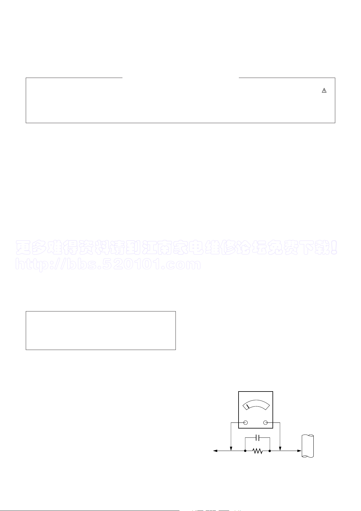
Leakage Current Hot Check (See below Figure)
Plug the AC cord directly into the AC outlet.
Do not use a line Isolation Transformer during this check.
Connect 1.5K/10watt resistor in parallel with a 0.15uF capacitor
between a known good earth ground (Water Pipe, Conduit, etc.)
and the exposed metallic parts.
Measure the AC voltage across the resistor using AC
voltmeter with 1000 ohms/volt or more sensitivity.
Reverse plug the AC cord into the AC outlet and repeat AC
voltage measurements for each exposed metallic part. Any
voltage measured must not exceed 0.75 volt RMS which is
corresponds to 0.5mA.
In case any measurement is out of the limits specified, there is
possibility of shock hazard and the set must be checked and
repaired before it is returned to the customer.
Leakage Current Hot Check circuit
The source of X-RAY RADIATION in this TV receiver is the
High Voltage Section and the Picture Tube.
For continued X-RAY RADIATION protection, the
replacement tube must be the same type tube as specified in
the Replacement Parts List.
1.5 Kohm/10W
To Instrument’s
exposed
METALLIC PARTS
Good Earth Ground
such as WATER PIPE,
CONDUIT etc.
AC Volt-meter
IMPORTANT SAFETY NOTICE
0.15uF
更多难得资料请到江南家电维修论坛免费下载!
http://bbs.520101.com
- 4 -
DESCRIPTION OF CONTROLS
All the functions can be controlled with the remote control handset.
Some functions can also be adjusted with the buttons on the front
panel of the set.
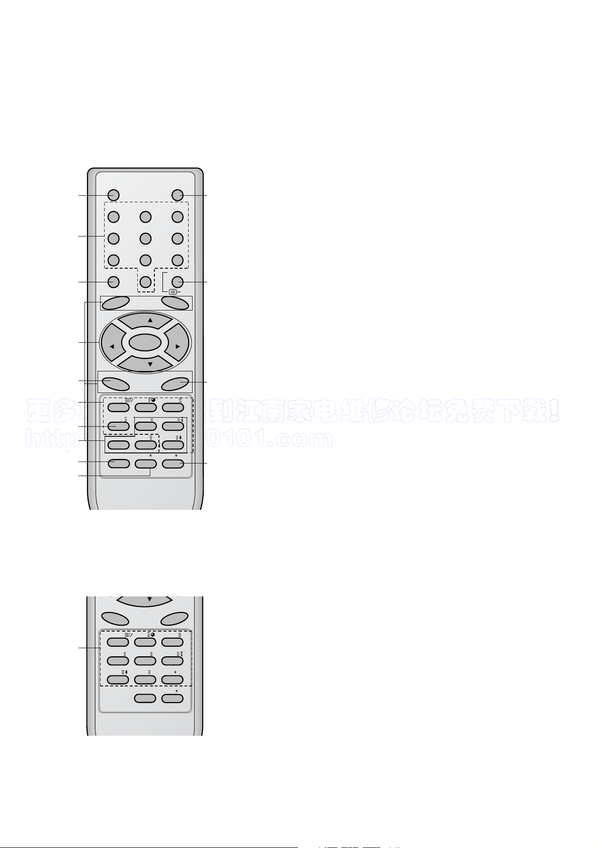
Remote control handset
Before you use the remote control handset, please install the batteries. See the next page.
1. POWER
switches the set on from standby or off to standby.
2. NUMBER BUTTONS
switches the set on from standby or directly select a number.
3. MENU
selects a menu.
4.
DD / EE
(Programme Up/Down)
selects a programme or a menu item.
switches the set on from standby.
scans programmes automatically.
FF / GG
(Volume Up/Down)
adjusts the volume.
adjusts menu settings.
OK
accepts your selection or displays the current mode.
5. TELETEXT BUTTONS (option)
These buttons are used for teletext.
For further details, see the ‘Teletext’ section.
6.
SLEEP
sets the sleep timer.
7. PIP BUTTONS (option)
PIP
switches the sub picture on or off.
PR +/-
selects a programme for the sub picture.
SWAP
alternates between main and sub picture.
INPUT
selects the input mode for the sub picture.
SIZE
adjusts the sub picture size.
STILL
freezes motion of the sub picture.
POSITION
relocates the sub picture in clockwise direction.
9/4 PIP
switches on or off the 9 or 4 sub pictures.
(With TELETEXT / PIP)
POWER MUTE
123
456
789
MENU
TV/AV
0
PR
PR
OK
VOLVOL
TV
SWAP
INPUT
PR+
PR-
TEXT/MIX/
SIZE/
PIP 9/4PIP i
X
M
POSITION/
STILL/
REVEAL/
?
SLEEPMODE/
EYE
/
TIME/
FAVOURITE
I/II/
1
2
3
4
6
5
13
7
8
9
10
11
12
14
PR
(With TELETEXT / Without PIP)
5
TEXT/MIX/
Q.VIEW
SLEEPMODE/
M
SIZE/
TIME/
UPDATE/
INDEX/ i
FAVOURITE
REVEAL/
X
LIST
HOLD/
EYE/
?
I/II/
更多难得资料请到江南家电维修论坛免费下载!
http://bbs.520101.com
- 5 -
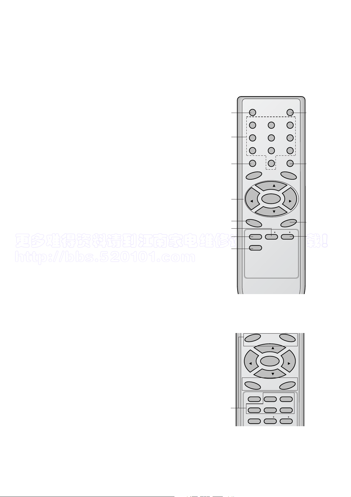
8. FAVOURITE
selects a favorite programme.
9.
EYE/
*
(option)
switches the eye function on or off.
10. MUTE
switches the sound on or off.
11. TV/AV
selects TV or AV mode.
switches the set on from standby.
exits the Teletext mode
12.
I/II/
*
selects the language during dual language broadcast.
selects the sound output (option).
13. Q.VIEW (or YELLOW)
returns to the previously viewed programme.
14.
LIST (or BLUE)
displays the programme table.
*
: No function
COLOURED BUTTONS : These buttons are used for teletext (only
TELETEXT models) or programme edit.
(Without TELETEXT / PIP)
PR
PR
OK
VOLVOL
TV
SWAP INPUT
PR+PR-
SLEEP
FAVOURITE
POSITION
9/4PIP
STILL
PIP
SIZE
EYE/
I/II/
(With PIP / Without TELETEXT)
POWER MUTE
123
456
789
MENU
TV/AV
0
PR
PR
OK
VOLVOL
SLEEP
FAVOURITE
EYE/
I/II/
Q.VIEW
LIST
1
2
3
4
13
6
9
8
10
11
12
14
7
更多难得资料请到江南家电维修论坛免费下载!
http://bbs.520101.com
- 6 -
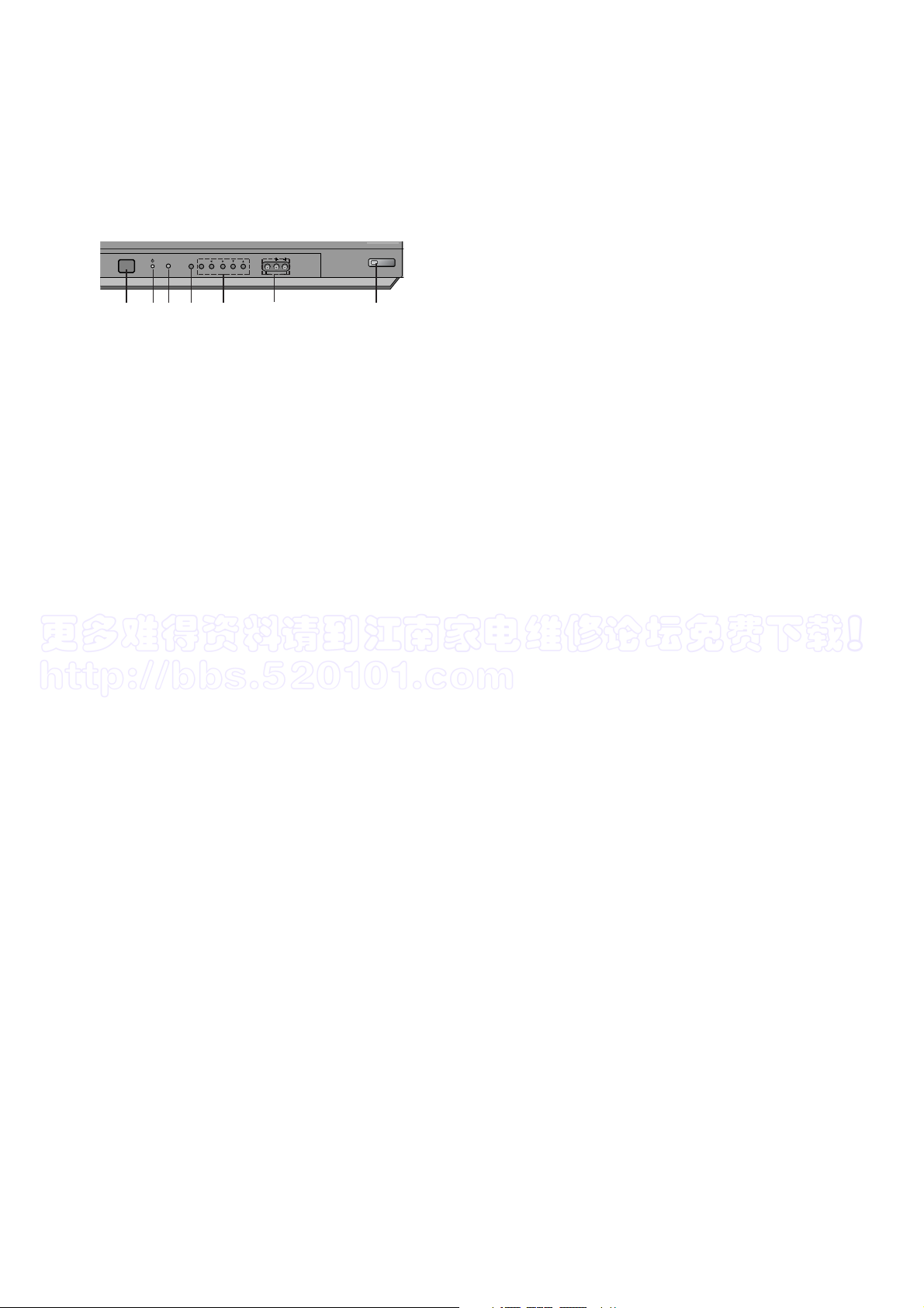
1. MAIN POWER (ON/OFF)
switches the set on or off.
2. POWER/STANDBY INDICATOR
illuminates brightly when the set is in standby mode.
dims when the set is switched on.
3. MENU
selects a menu.
4. OK
accepts your selection or displays the current mode.
FF / GG
(Volume Down/Up)
adjusts the volume.
adjusts menu settings.
DD / EE
(Programme Up/Down)
selects a programme or a menu item.
switches the set on from standby.
5. REMOTE CONTROL SENSOR
Note : Only use the supplied remote control handset. (When you use others, they’ll be not able to
function.)
6. AUDIO/VIDEO IN SOCKETS (AV IN3)
Connect the audio/video out sockets of external equipment to these sockets.
7. EYE (option)
adjusts picture according to the surrounding conditions.
FRONT
ON/OFF
MENU
OK
VOL PR
VIDEO
AUDIO
L
R
AV IN3
2 5 3 4
1
7
6
更多难得资料请到江南家电维修论坛免费下载!
http://bbs.520101.com
- 7 -
SPECIFICATIONS
Note : Specification and others are subject to change without notice for improvement.
V Scope
This specification can be applied to all the television related to
CW62A Chassis.
V Test and Inspection Method
1) performance : Follow the Standard of LG TV test
2) Standards of Etc. requirement
- Safety: IEC60065
- EMC: EN55020,EN55013
V Test Condition
1) Temperature : 20 ± 5°C(CST : 40 ±5°C)
2) Relative Humidity : 65
± 10%
3) Power voltage : AC110-240V~, 50/60Hz
4) Follow each drawing or spec for spec and performance of
parts,based upon P/N of B.O.M
5) Warm up TV set for more than 20min. before the
measurement.
No
1
2
3
4
5
6
7
8
Item
Receiving System
Available Channel
Input Voltage
Market
Screen Size
Tuning System
Operating Environment
Storage Environment
Remark
EU/ Non EU
OPTION
Non EU/ EU
NTSC-M
Non EU
EU
200 PR(W/O TXT)
Specification
PAL,SECAM BG
PAL/SECAM DK
PAL-I/I
NTSC M
NTSC 4.43(AV)
SECAM-L/L’
NTSC M/ PAL M/N
VHF : E2 ~ E12
UHF : E21 ~ E69
CATV : S1 ~ S20
HYPER : S21 ~ S41
VHF : 02 ~ 13
UHF : 14 ~ 69
CATV : 02 ~ 13
AC 110-240V, 50/60Hz
AC 230V, 50/60Hz
EU,CIS, China, Asia, Africa
Flat 29”
FVS 100Program
1) Temp : 0 ~ 45 deg
2) Humidity : below 85%
1) Temp : -20 ~ 60 deg
2) Humidity : below 85%
V General Specification
更多难得资料请到江南家电维修论坛免费下载!
http://bbs.520101.com
1. Application Object
These instructions are applied to all of the color TV, CW62A.
2. Notes
(1) Because this is not a hot chassis, it is not necessary to use
an isolation transformer. However, the use of isolation
transformer will help protect test instrument.
(2) Adjustment must be done in the correct order.But the
adjustment can be changed by consideration of mass
production.
(3) The adjustment must be performed in the circumstance of
25±5°C of temperature and 65±10% of relative humidity if
there is no specific designation.
(4) The input AC voltage of the receiver must keep rating
voltage in adjusting.
(5) The receiver must be operated for about 15 minutes prior
to the adjustment.
(6) Signal: Received, the standard color signal.(65dB±1dB uV)
LG standard signal means the digital pattern
(PAL_EU 05CH).
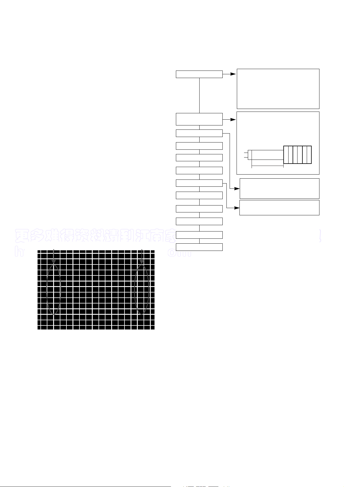
3. Focus adjustment
(1) Receive the Cross-Hatch Pattern(Fig 1).
(2) Set the picture condition on “DYNAMIC(CLEAR)” mode.
(3) Adjust the Focus volume of FBT for the best focus of (A) &
(B).
4. Purity & Convergence adjustment
Adjustment should be operated when using the CPT(without
ITC from CPT manufacturing place)
This adjustment must be done in the order of the following
flowchart.
4.1. Color purity adjustment
(1) It makes CPT or CABINET enough to demagnetization.
(2) Receive the signal of red raster.
(3) Loosen fixed screw of DY and closely to CPT funnel part.
(4) Check the center of screen that PURITY MAGNET of CPT
by crossing adjustment. At this time, 4 & 6 pole magnet is
located to magnet of nothing.
(5) Move the DY to make equal red on whole screen and it
does not to make the DY by fixed screw after check a
simple color of Red/Green/Blue and white raster whether or
not it is a pollution of color.
(At this time, take care raster of screen and DY must fixing
in the condition which maintains a horizontality.)
(6) Check the TV set by move direction.
4.2. Convergence adjustment
These adjustments can the best condition of focus after
finished purity adjustment.
(1) Receive the signal of cross hatch that BACK RASTER is
black.
(2) Adjust brightness and luminosity till dot appear 9 ~12.
(3) Open angle of the two tab of 4 pole MAGNET by isogonic
angle and accord with vertical line of red and blue color in
the middle of screen.
(4) Maintain as angle of (3) and rotate the tab to accord with
vertical line of Red and Blue color in the middle of screen.
- 8 -
ADJUSTMENT INSTRUCTIONS
A
B
<Fig 1. Cross-Hatch Pattern(E-7CH)>
Assembling DY to
CPT
CPT Assembling
As preparatory operations before
assembling CPT, wind cotton Tape for
protecting to CPT NECK and DY, CPT
connection parts. At this moment, end
of tape should be over-lapped and
wound in direct route to the NECK.
Let the screen Standard condition.
Operate Heat-Run at least 15
minutes.
Torque is to be 9-11 kg f.cm when
fixing DY.
Fix the Magnet to the position as
shown picture below. Be careful not to
make CPT neck shadow while
adjusting DY.
HEAT RUN
Degaussing
STC Pre-Adjustment
PURITY Adjustment
DY Fixing
SCREEN Voltage adj.
W/B Fixing
FOCUS not yet ADJ.
STC not yet ADJ.
DYC not yet ADJ.
Convergence Magnet
◀
15 ~ 20mm
6Pole
◀
4
2
更多难得资料请到江南家电维修论坛免费下载!
http://bbs.520101.com
(5) Open angle of the two tab of 6 pole magnet by isogonic
angle and accord with vertical line of Red/Blue and Green.
(6) Maintain as angle of (5) and rotate the tab to accord with
horizontal line. In case of twisted horizontal line,repeat
adjustment of (3) ~ (5) remembering the movement of
Red/Green/Blue color.
(7) Move the DY to best condition of convergence and attach
the CPT to a rubber-chock for fixing DY.
5. Screen voltage adjustment
(1) Receive the PAL or SECAM(NTSC) signal into RF mode
(regardless of channel).
(2) If you press the “ADJ”button in LINE SVC mode(IN-START
button),the LINE SVC mode changes to screen adjustment
mode.
(3) Turn the Screen Volume of FBT to change luminance of
White signal center as shown below.
(4) Press the ADJ button to exit SVC mode.
6. White balance adjustment
NOTE : When adjusting white balance automatically,connect the
adjustment JIG in SVC mode.(When pressing INSTART,MUTE button on remote control for adjustment
orderly,it is changed to CPU OFF mode and screen is
displayed to “CPU OFF”.)
(1) Receive 100% white pattern.
(2) Adjust LOW Light status(4.5FL) of CR(R CUT), CB(B CUT)
at CG(G CUT:75) : 60.
(3) Adjust HIGH Light status(35FL) of WR(R DRIVE), WB(B
DRIVE) at WG(G DRIVE:380) : 450.
(4) Repeat above step (2) and (3) for the best condition each
status of High Light and Low Light.
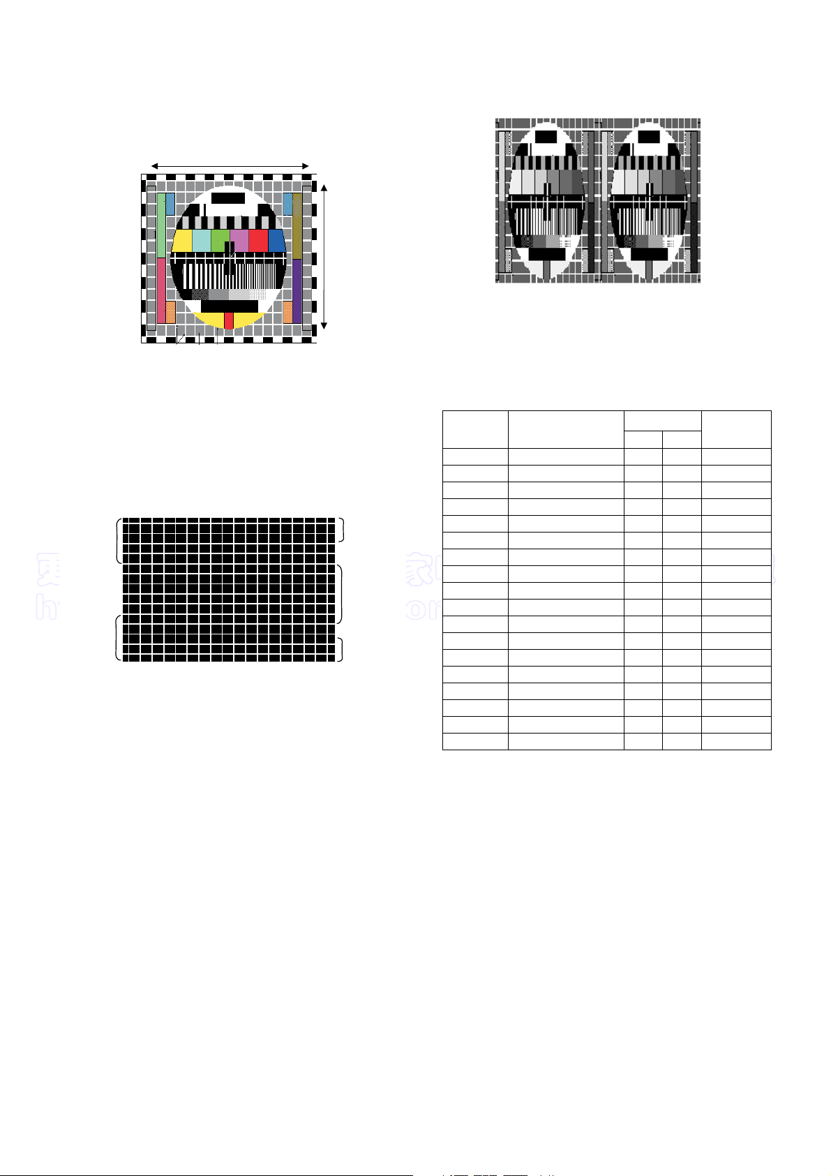
7. Deflection setting Data Adjustment
7.1 Adjustment preparation
(1) Tune the TV set to receive an Digital pattern(EU05CH).
(2) Deflection setting data adjustment is operate by SVC
communicator.
(3) Enter the deflection mode by selection SERVICE2 key on
SERVICE MENU after enter the adjustment mode by
pressing LINE SVC MODE(IN-START KEY).
(4) Use the CH D ,E key to select adjustment item.
(5) Use the VOL F ,G key to increase/decrease data.
7.2 Adjustment
<Note>
- When adjusting a deflection,adjust N50Hz of PAL signal first and
adjust a deflection data at N60Hz(NTSC), Z60Hz, N50Hz,
W50Hz, Z50Hz.
- After finishing deflection adjustment, press the ENTER
button to enter or exit SVC mode.
(1) H SHIFT
Adjust so that the geometric horizontal center line is in
accord with horizontal center line of CPT.
(2) H PARALLEL
Adjust vertical inclination of screen.
(3) H BOW
After finishing Cushion adjustment, adjust curved rate of
top & bottom corner to be equal.
(4) V LINEAR
Adjust the top & bottom size of inner circle to be equal.
(5) V SCROLL
Adjust so that the geometric vertical center line is in accord
with vertical center line of CPT.
2. White balance IIC Parameter(Address)
Program
Sub Add
Start Bit
Stop Bit
Offset
Polarity
EP_Rom_S
B(R)_Amp
Win31_wb TWB
20
5
0
0
1
36
B(R)_Cut
Win31_wb TWB
17
5
0
0
1
33
G_Amp
Win31_wb TWB
21
5
0
2
0
37
- 9 -
Menu
X
Y
Color Temperature
288
295
9000
o
K
268
273
13000
o
K
EU
N-EU
<Table 1> White Balance Color analyzer
Menu
BLO-R(R CUT)
BLO-G(G CUT)
BLO-B(B CUT)
RG(R DRIVE)
GG(G DRIVE)
BG (B DRIVE)
LOW LIGHT
HIGH LIGHT
0 ~ 63
0 ~ 63
0 ~ 63
0 ~ 63
0 ~ 63
0 ~ 63
32
32
FIX
32
32
32
Range
DATA
<Table 2> White Balance Initial Data
<Table 3> White Balance Initial Data
1. IC
VCD IC
EP_ROM
0000
Name
Maker Algorithm
Program
Vcd Slave
Win31_wb
TWB
8A
Eeprom_Slave
Win31_wb
TWB
A0
Speed1Delay
30
G_Cut
Win31_wb TWB
18
5
0
2
0
34
Speed/ Plus 2 2 2 2
更多难得资料请到江南家电维修论坛免费下载!
http://bbs.520101.com
(6) EW WIDTH
Adjust until the outmost left and right lattice of received
pattern is accord with 25% of other lattice width.
(7) EW PARABOLA
Adjust so that middle portion of the outermost left and right
vertical line look like parallel with vertical lines of the CPT.
(8) EW UPCORNER & (9) EW LOCORNER
After finished cushion adjustment, adjust vertical line of lefttop, right-top, left-bottom, right-bottom of screen to the best
straight line.
(10) EW TRAPEZOID
Adjust to make the length of top horizontal line same with it
of the bottom horizontal line.
(11) V SLOPE
(12) V AMPLITITUE
Adjust so that the circle of a digital circle pattern should be
located interval of 6~7mm from the effective screen of the
CPT.
(13) S CORRECTION
Adjust so that all distance between each lattice width of
top/center/bottom are to be the same.
(14) V SHIFT
Adjust so that the geometric vertical center line is in accord
with vertical center line of CPT.
(15) V ZOOM (VERTICAL ZOOM)
(16) PIP_H(PIP H Position) adjustment - option
Adjust the H-Position by using VOL +/- key until PIP picture
is in contact with main picture.
8. Deflection setting initial data
<Table 4> Deflection setting initial data (SERVICE 2)
* Fix : Don’t change data
- After finishing deflection adjustment at PAL 50Hz, NTSC 60Hz
is applied deflection compensation value. But recheck condition
of adjustment at NTSC system and adjust deflection data if
necessary.
- Adjust PIP Position adjustment at only PAL 50Hz.
- 10 -
<Fig. 2>PAL Digital pattern (EU05CH)
<Fig. 4> PIP H Position
34
32
32
44
30
57
15
45
50
25
25
29
30
54
25
0
0
0
50Hz 60Hz
<Fig. 3> Cross-Hatch Pattern(E-7CH)
CRNU
CRNL
CRNU6
EP
CRNL6
Item
H-SHIFT
H PARALL
H BOW
V LINEAR
V SCROLL
EW WIDTH
EW PARAB
EW UPCOR
EW LOCOR
EW TRAPE
V SLOPE
V AMPLIT
SCORRECT
V SHIFT
V ZOOM
V SYNSLI
OVRVOLIN
VGUARD
Horizontal shift
Horizontal parallelogram
Bow
Vertical linearity
Vertical scroll
EW width
Parabola adj
Upper corner adj
Lower corner adj
Trapezoid adj
Vertical slope
Vertical amplitude
S correction
Vertical shift
Vertical zoom
Vertical slicing level
Over voltage input mode
Vertical guard mode
24
32
32
41
30
57
18
49
53
25
17
34
35
46
25
0
0
0
Adjust
Recommend
Recommend
Recommend
Adjust
Adjust
Adjust
Adjust
Adjust
Adjust
Recommend
Recommend
Recommend
Recommend
Fix
Fix
Fix
Fix
Description
29”
Adjust
 Loading...