

LG 17LS5R-ZA, 20LS5R-ZA, 20LS5RC-ZA, 19LS4R-ZA, 22LS4R-ZA Owner's Manual
...
LCD TV
OWNER’S MANUAL
LCD TV MODELS
19LS4R
*
22LS4R
*
17LS5R
*
20LS5R
*
Please read this manual carefully before operating your set.
Retain it for future reference.
Record model number and serial number of the set.
See the label attached on the back cover and quote
this information to your dealer when you require service.
ENGLISH
Ofrecido por www.electromanuales.com

Ofrecido por www.electromanuales.com
1
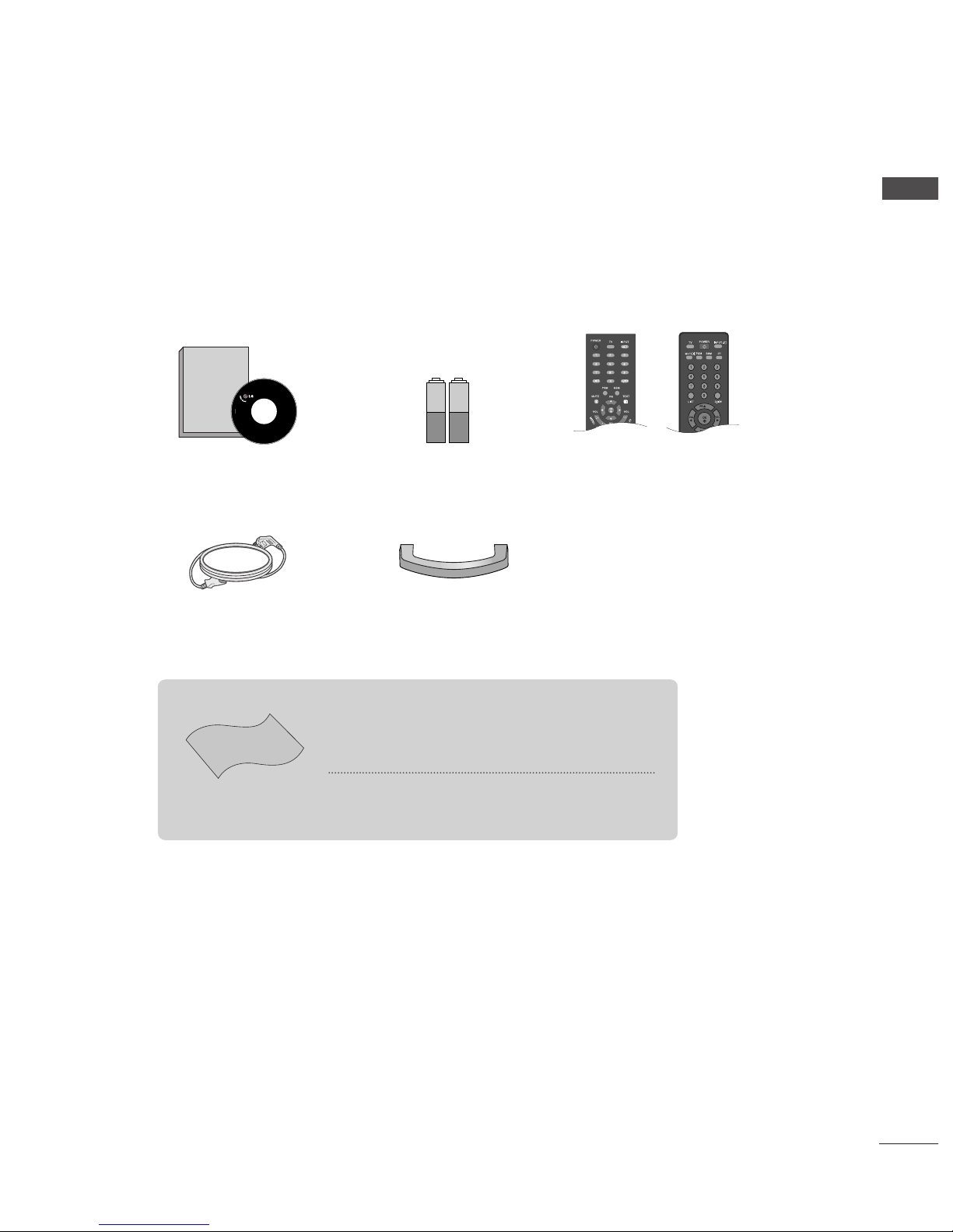
ACCESSORIES
Ensure that the following accessories are included with your TV. If any accessory is missing, please contact
the dealer where you purchased the product.
Owner’s Manual Batteries Remote Control
or
Power Cord
Cable Management
ACCESSORIES
Polishing Cloth
Polish the screen with the cloth
This feature is not available
for all models.
*Slightly wipe stained spot on the exterior only with the cleans-
ing cloths for the product exterior if there is stain or fingerprint on
surface of the exterior.
Do not wipe roughly when removing stain. Please be cautious of
that excessive power may cause scratch or discoloration.
Owner's
Manual
Owner’s manual
Ofrecido por www.electromanuales.com

PREPARATION
Front Panel Controls....................................................... 4
Back Panel Information .................................................. 6
Stand Installation............................................................. 9
Detaching stand..............................................................10
Back Cover for Wire Arrangement ............................ 11
Wall Mount: Horizontal installation.......................... 12
Desktop Pedestal Installation..................................... 12
Positioning your display............................................... 13
Location............................................................................ 13
Kensington Security System........................................14
Antenna Connection .................................................... 15
PICTURE CONTROL
Picture Size (Aspect Ratio)Control...........................40
Preset Picture Settings
- Picture Mode-Preset..............................................42
- Auto Color Tone Control(Warm/Normal/Cool)
.....43
Manual Picture Adjustment
- Picture Mode-User Option .................................44
- Color Tone - User Option ...................................45
-
Picture Improvement Technology
....................46
Demo...................................................................47
Cinema ..............................................................................48
Picture Reset....................................................................49
SOUND & LANGUAGE CONTROL
Auto Volume Leveler......................................................50
Preset Sound Settings - Sound Mode ......................51
Sound Setting Adjustment - User Mode .................52
Balance..............................................................................53
I/II
- Stereo/Dual Reception.........................................54
- NICAM Reception ..................................................55
- Speaker Sound Output Selection......................55
On-Screen Menus Language /Country Selection
.... 56
EXTERNAL EQUIPMENT SETUP
HD Receiver Setup .........................................................16
DVD Setup....................................................................... 18
VCR Setup ...................................................................... 20
Headphone SETUP ........................................................23
PC Setup...........................................................................24
Screen Setup for PC Mode..........................................27
WATCHING TV /PROGRAMME CONTROL
Remote Control Key Functions...................................28
Turning on the TV......................................................... 30
Programme Selection ................................................... 30
Volume Adjustment........................................................30
On Screen Menus Selection and Adjustment.........31
Auto Programme Tuning.............................................. 32
Manual Programme Tuning ......................................... 33
Fine Tuning .......................................................................34
Assigning a Station Name............................................35
Programme Edit ............................................................. 36
Favourite Programme.................................................... 37
Calling the Programme Table ..................................... 38
Child lock ........................................................................ 39
PREPARATION
PICTURE CONTROL
WATCHING TV / PROGRAMME CONTROL
2
CONTENTS
AACCCCEESSSSOORRIIEESS
......................................................1
CONTENTS
Ofrecido por www.electromanuales.com

3
CONTENTS
APPENDIX
Troubleshooting..............................................................64
Maintenance ...................................................................66
Product Specifications..................................................67
TIME SETTING
Clock Setup......................................................................57
Auto On/Off Timer Setting .........................................58
Sleep Timer Setting........................................................59
Auto Shut-off Setting ....................................................60
TELETEXT
Switch On/Off ...............................................................61
SIMPLE Text .....................................................................61
TOP Text ...........................................................................62
FASTEXT...........................................................................62
Special Teletext Functions............................................63
Ofrecido por www.electromanuales.com

4
PREPARATION
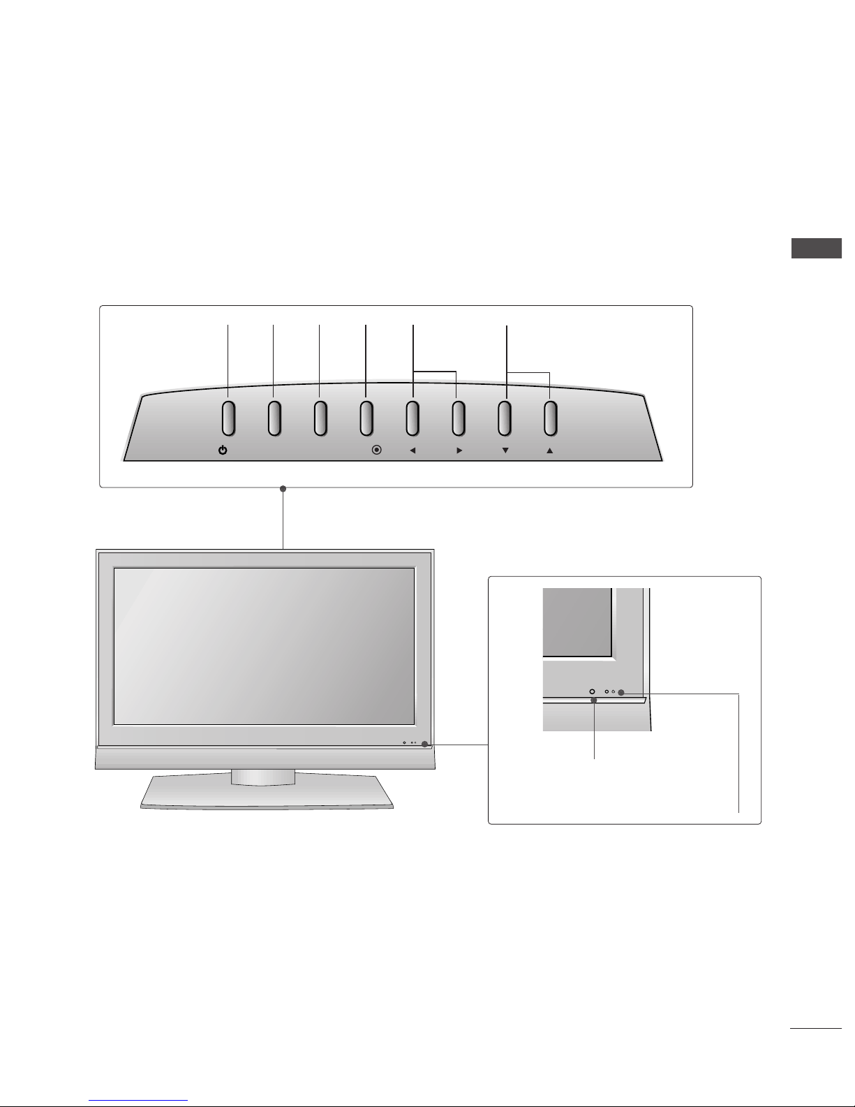
FRONT PANEL CONTROLS
PREPARATION
■
This is a simplified representation of the front panel. Here shown may be somewhat different from your TV.
■
If your TV has the protection film, wipe the stand with polishing cloth after removing the protection film
attached to the stand.
17LS5R*/ 20LS5R*
INPUT
MENU
VOL
PR
/I
OK
INPUT
MENU
VOL
PR
/I
OK
PROGRAMME
Buttons
VOLUME
Buttons
MENU
Button
OK
Button
INPUT
Button
POWER
Button
Remote Control
Sensor
Power/Standby Indicator
• illuminates red in standby mode.
• illuminates green when the set is switched on.
17LS5R*
20LS5R*
Ofrecido por www.electromanuales.com
5
PREPARATION
Remote Control Sensor
Power/Standby Indicator
• illuminates red in standby mode.
• illuminates green when the set is switched on.
19LS4R*/ 22LS4R*
INPUT
MENU
VOL
PR
/I
OK
PROGRAMME
Buttons
VOLUME
Buttons
MENU
Button
OK
Button
INPUT
Button
POWER
Button
Ofrecido por www.electromanuales.com
6
PREPARATION
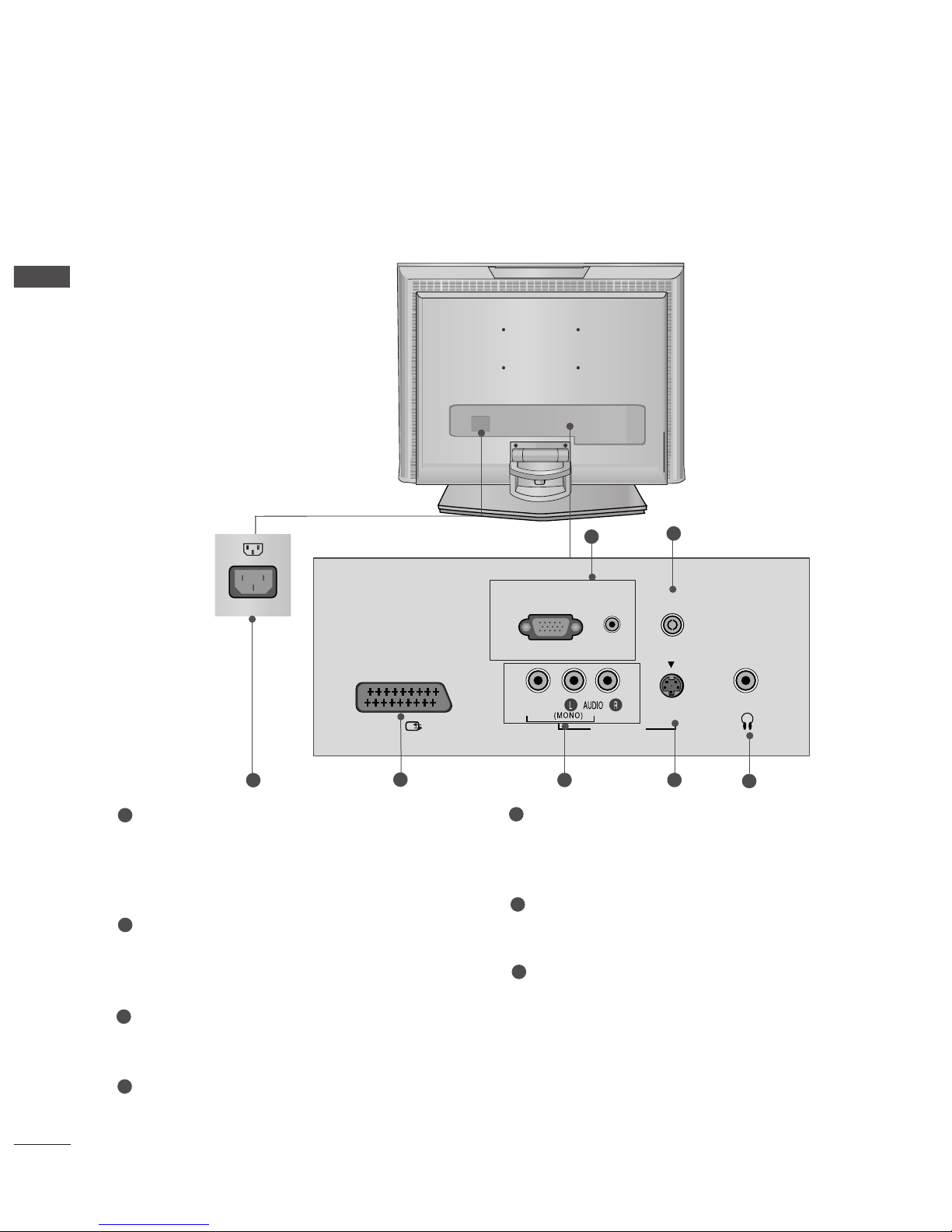
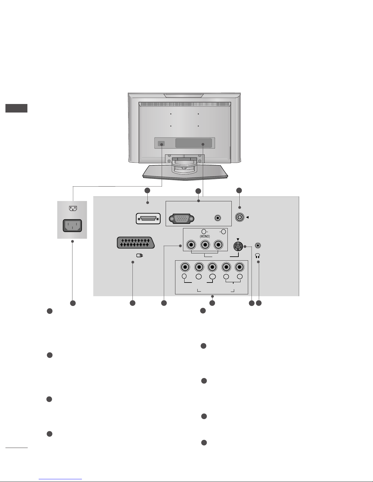
BACK PANEL INFORMATION
PREPARATION
■
This is a simplified representation of the back panel. Here shown may be somewhat different from your TV.
17LS5R*
H/P
RGB(PC/DTV) IN
ANTENNA IN
AUDIO
(RGB) IN
S-VIDEO
AV IN 2
VIDEO
AV 1
2
3
4
5 6
7
1
Power Cord Socket
This TV operates on an AC power. The voltage is
indicated on the Specifications page. Never
attempt to operate the TV on DC power.
RGB/Audio Input
Connect the monitor output from a PC/DTV to
the appropriate input port.
Antenna Input
Connect over-the-air signals to this jack.
Euro Scart Socket (AV1)
Connect scart socket input or output from an
external device to these jacks.
Audio/Video Input
Connect audio/video output from an external
device to these jacks.
S-Video Input
Connect S-Video out from an S-VIDEO device.
Headphone Input
1
2
3
4
5
6
7
17LS5R*
Ofrecido por www.electromanuales.com
7
PREPARATION
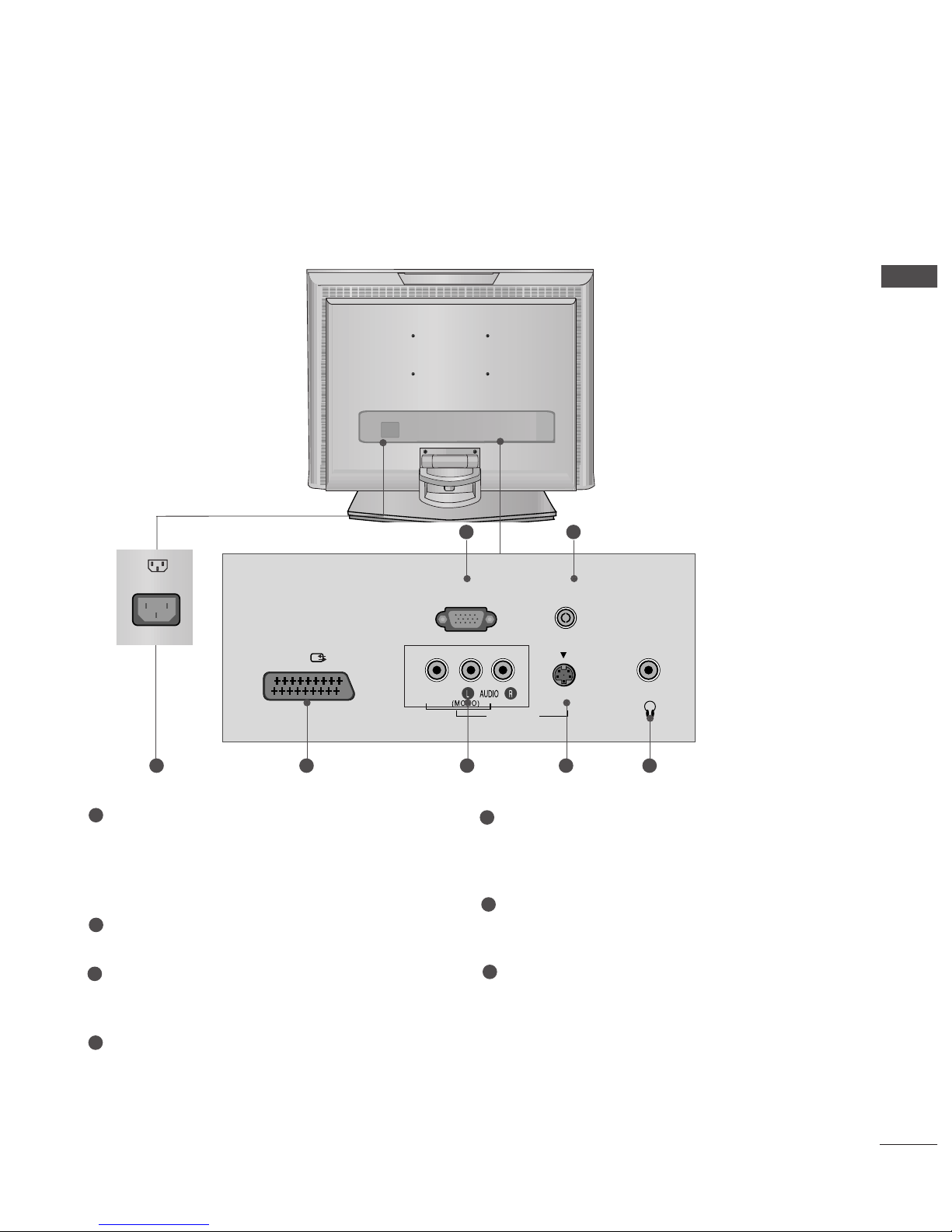
20LS5R*
Power Cord Socket
This TV operates on an AC power. The voltage is
indicated on the Specifications page. Never
attempt to operate the TV on DC power.
SERVICE ONLY
Antenna Input
Connect over-the-air signals to this jack.
Euro Scart Socket (AV1)
Connect scart socket input or output from an
external device to these jacks.
Audio/Video Input
Connect audio/video output from an external
device to these jacks.
S-Video Input
Connect S-Video out from an S-VIDEO device.
Headphone Input
1
2
3
4
5
6
7
H/P
ANTENNA IN
S-VIDEO
AV IN 2
VIDEO
AV 1
SERVICE ONLY
32
5 6 741
AC IN
Ofrecido por www.electromanuales.com
8
BACK PANEL INFORMATION
PREPARATION
PREPARATION
19LS4R* / 22LS4R*
RGB (PC/DTV) IN
AV 1
S-VIDEO
AV IN 2
VIDEO
L
R
AUDIO
Y
PB
PR
LR
VIDEO
COMPONENT IN
AUDIO
HDMI/DVI IN
AUDIO
(RGB/DVI) IN
H/P
ANTENNA IN
2
3
4
5 96 7
Power Cord Socket
This TV operates on an AC power. The voltage is
indicated on the Specifications page. Never
attempt to operate the TV on DC power.
HDMI/DVI IN Input
Connect a HDMI signal to HDMI IN.
Or DVI(VIDEO)signal to HDMI/DVI port with DVI
to HDMI cable.
RGB/Audio Input
Connect the monitor output from a PC/DTV to
the appropriate input port.
Antenna Input
Connect over-the-air signals to this jack.
Euro Scart Socket (AV1)
Connect scart socket input or output from an
external device to these jacks.
Audio/Video Input
Connect audio/video output from an external
device to these jacks.
Component Input
Connect a component video/audio device to
these jacks.
S-Video Input
Connect S-Video out from an S-VIDEO device.
Headphone Input
1
2
3
4
5
6
7
8
9
8
1
Ofrecido por www.electromanuales.com
9
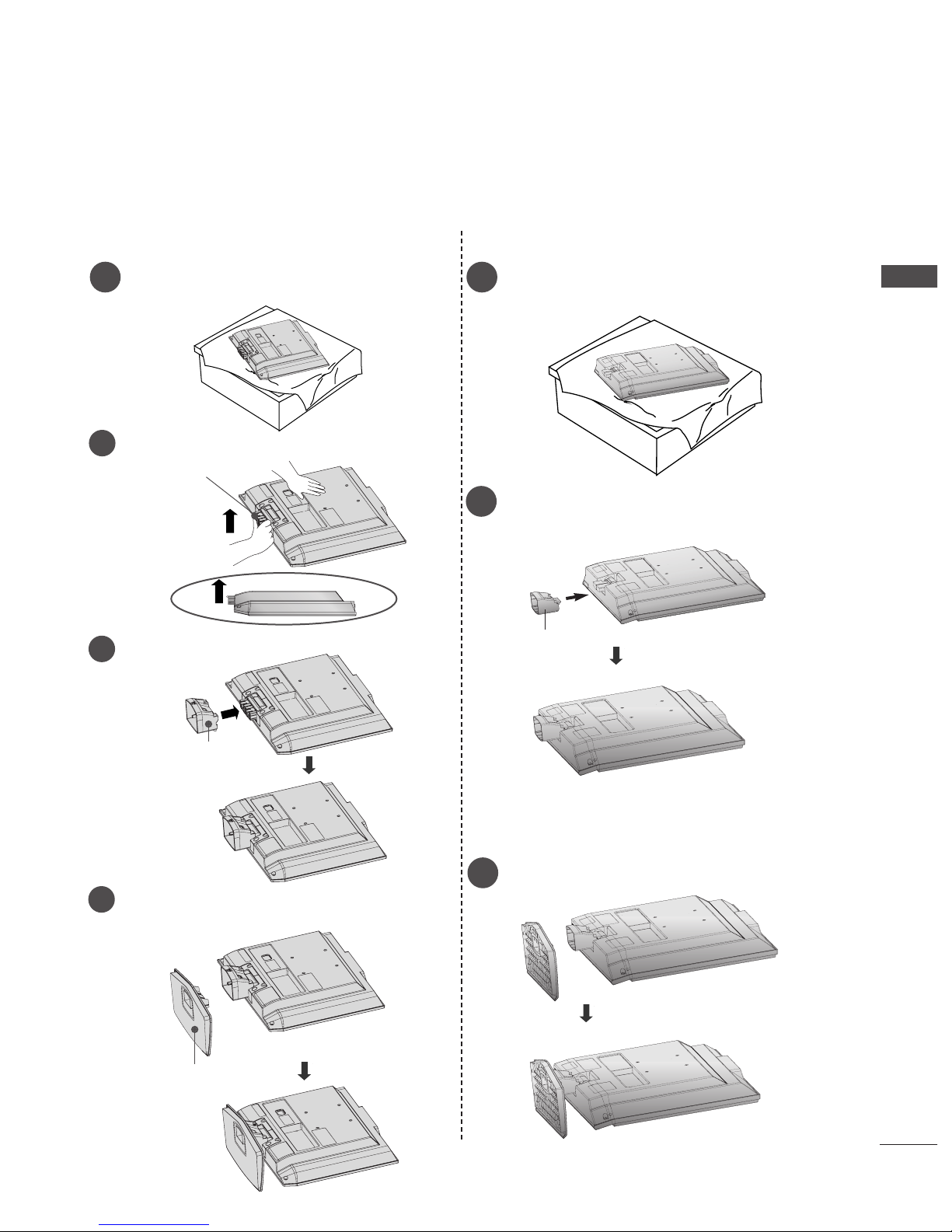
STAND INSTALLATION
PREPARATION
1
Carefully place the product screen side down on a cushioned
surface that will protect product and screen from damage.
■
Here shown may be somewhat different from your TV.
3
Place the product stand on the product as shown.
3
Place the product stand on the product as shown.
17/20LS5R*
1
Carefully place the product screen side down on a cushioned
surface that will protect product and screen from damage.
19/22LS4R*
2
Assemble parts of stand body with
the product
of the stand.
Insert stand body into
the product
until clicking sound.
stand body
Hold the
hh iinnggee bboodd yy
and bend it upward.
2
Hinge Body
Insert the
ssttaanndd bbooddyy
into the product until clicking sound.
Stand Body
3
Assemble the parts of the
sstt aanndd bboodd yy
with
cc oovveerr bbaassee
of the product.
4
Cover Base
Ofrecido por www.electromanuales.com
10
PREPARATION
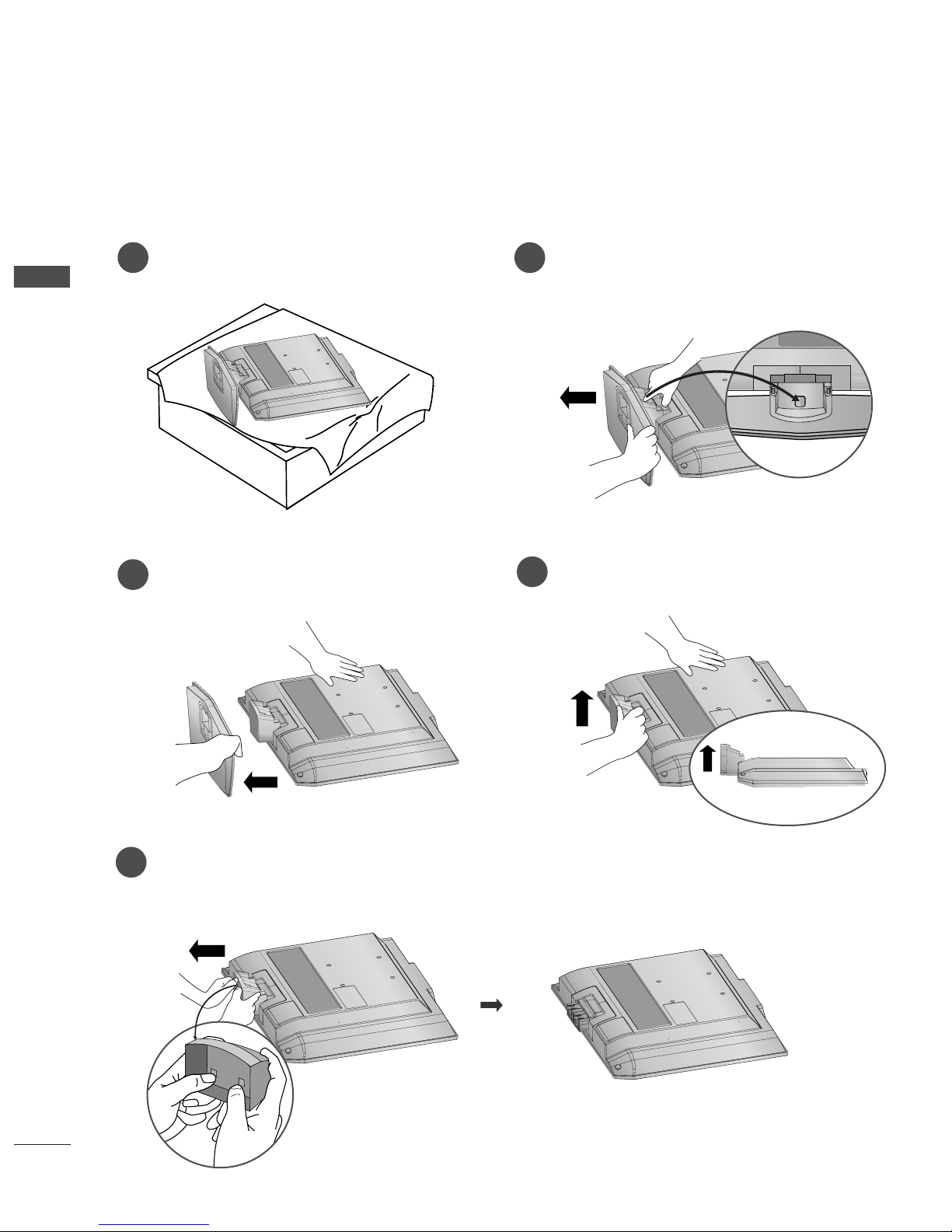
DETACHING STAND
PREPARATION
1
2
3
Place the set with its front facing downward on a
cushion or soft cloth.
Pull cover base backward during pressing botton
on stand body.
Hold cover base and pull with shake it backward
to separate from stand body.
4
Hold the stand and bend it upward.
5
Pull stand body to separate from set during
pressing 2 latches.
■
Here shown may be somewhat different from your TV.
Ofrecido por www.electromanuales.com
11
PREPARATION
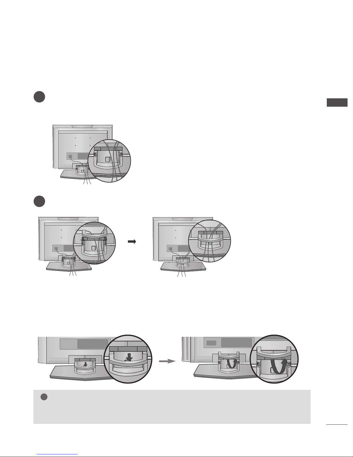
BACK COVER FOR WIRE ARRANGEMENT
Connect the cables as necessary.
To connect an additional equipment, see the
EExxtteerrnnaall eeqquuiippmmeenntt CCoonnnneeccttiioonnss
section.
1
Install the
CCAABBLLEE MMAANNAAGG EEMMEENNTT
as shown.
2
First, press the cable management. Hold the
CCAABBLLEE MMAANNAAGG EEMMEENNTT
with both hands and pull it upward.
NOTE
!
GG
Do not hold the
CCAABBLLEE MMAANNAAGG EE MMEENNTT
when moving the product.
- If the product is dropped, you may be injured or the product may be broken.
How to remove the cable management
■
Here shown may be somewhat different from your TV.
Ofrecido por www.electromanuales.com
12
PREPARATION
PREPARATION
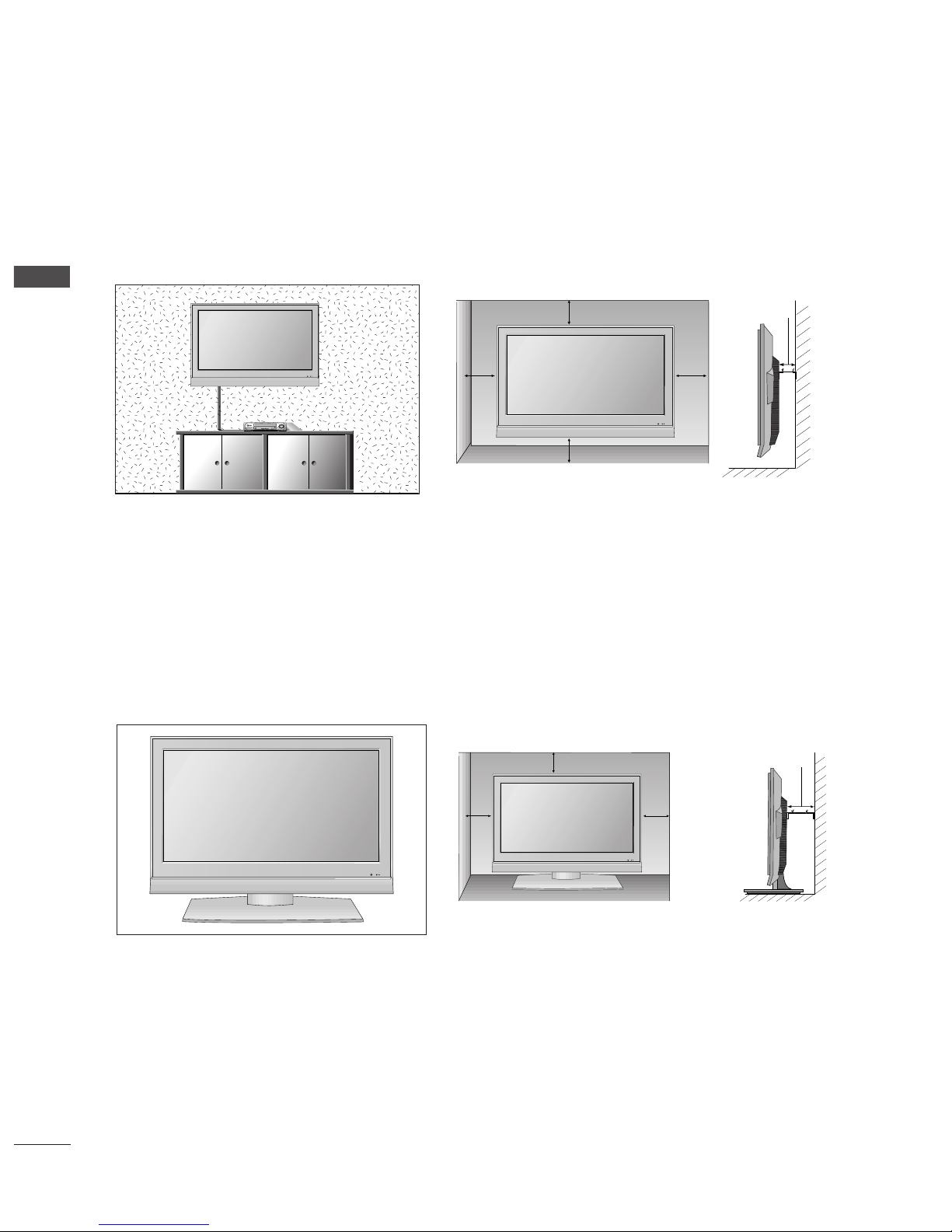
DESKTOP PEDESTAL INSTALLATION
For proper ventilation, allow a clearance of 4inches on each side from the wall.
WALL MOUNT: HORIZONTAL INSTALLATION
For proper ventilation, allow a clearance of 4" on each side and from the wall. Detailed installation
instructions are available from your dealer, see the optional Tilt Wall Mounting Bracket Installation and
Setup Guide.
4 inches
4 inches
4 inches 4 inches
4 inches
4 inches
4 inches4 inches
4 inches
Ofrecido por www.electromanuales.com

13
POSITIONING YOUR DISPLAY
PREPARATION
■
Here shown may be somewhat different from your TV.
Adjust the position of the panel in various ways for maximum comfort.
•• TTiilltt rr aa nnggee
8~12
3
0
12~10
3
0
LOCATION
Position your set so that no bright light or sunlight falls directly onto the screen. Care should be taken
not to expose the set to any unnecessary vibration, moisture, dust or heat. Also ensure that the set is
placed in a position to allow a free flow of air. Do not cover the ventilation openings on the back cover.
If you intend to mount the TV to a wall, attach VESA standard mounting interface (optional parts) to the
back of the TV.
When you install the set to use the wall mounting bracket (optional parts), fix it carefully so as not to drop.
17/20LS5R* 19/22LS4R*
Ofrecido por www.electromanuales.com
14
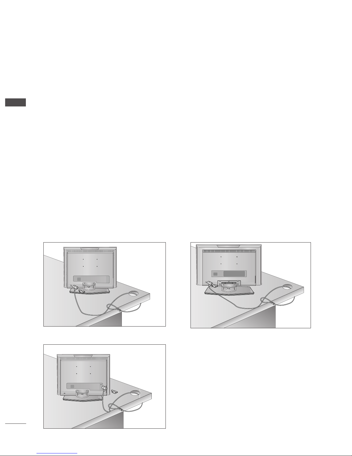
KENSINGTON SECURITY SYSTEM
PREPARATION
PREPARATION
17LS5R
*
20LS5R
*
19/22LS4R
*
- The TV is equipped with a Kensington Security System connector on the back panel. Connect the
Kensington Security System cable as shown below.
- For the detailed installation and use of the Kensington Security System, refer to the user’s guide provided
with the Kensington Security System.
For further information, contact
hhttttpp::////wwwwww..kkee nnssii nnggttoo nn..ccoomm
, the internet homepage of the
Kensington company. Kensington sells security systems for expensive electronic equipment such as notebook PCs and LCD projectors.
NOTE
- The Kensington Security System is an optional accessory.
NOTES
a. If the TV feels cold to the touch, there may be a small “flicker” when when it is turned on.
This is normal, there is nothing wrong with TV.
b. Some minute dot defects may be visible on the screen, appearing as tiny red, green, or blue spots.
However, they have no adverse effect on the monitor's performance.
c. Avoid touching the LCD screen or holding your finger(s) against it for long periods of time.
Doing so may produce some temporary distortion effects on the screen.
Ofrecido por www.electromanuales.com
15
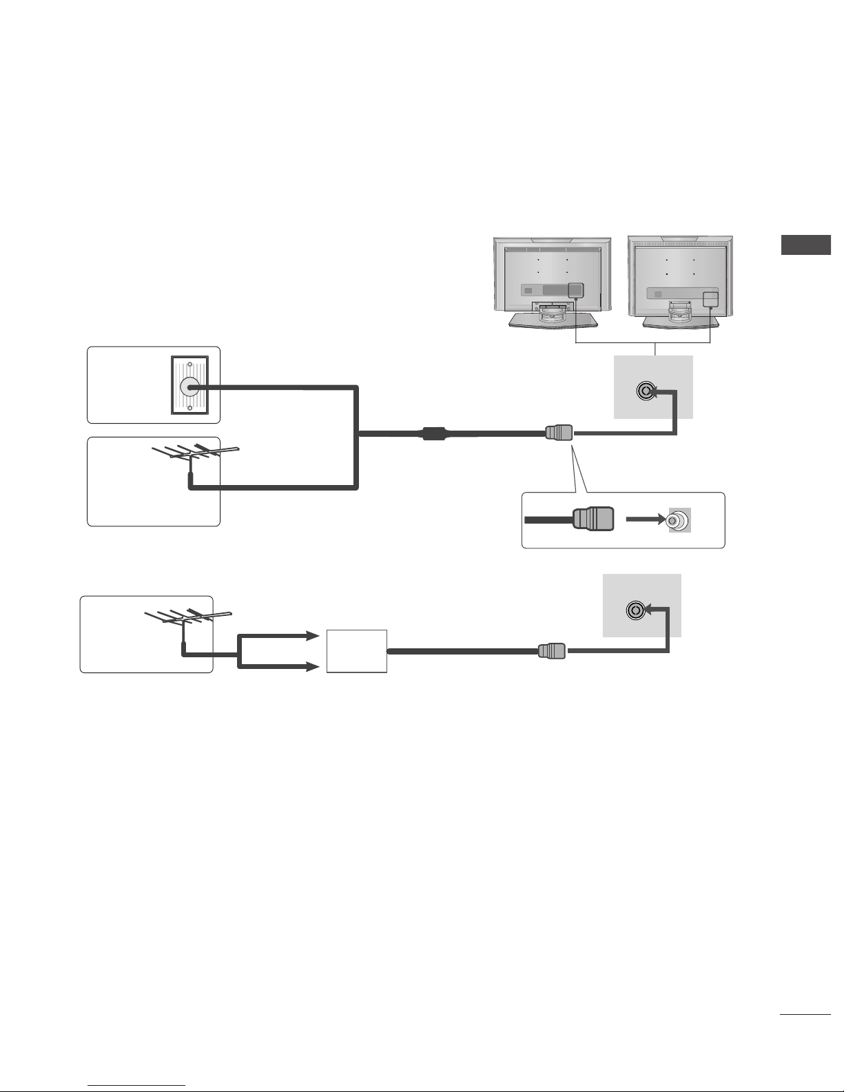
ANTENNA CONNECTION
PREPARATION
ANTENNA IN
ANTENNA IN
■
For optimum picture quality, adjust antenna direction.
■
An antenna cable and converter are not supplied.
Multi-family Dwellings/Apartments
(Connect to wall antenna socket)
Single-family Dwellings /Houses
(Connect to wall jack for outdoor antenna)
Outdoor
Antenna
Antenna
Wall
Antenna
Socket
RF Coaxial Wire (75 ohm)
UHF
Signal
Amplifier
VHF
■
In poor signal areas,to get better picture quality, install a signal amplifier to the antenna as shown as above.
■
If signal needs to be split for two TVs,use an antenna signal splitter for connection.
■
To prevent the equipment damage, never plug in any power cords until you have finished connecting all equipment.
Ofrecido por www.electromanuales.com
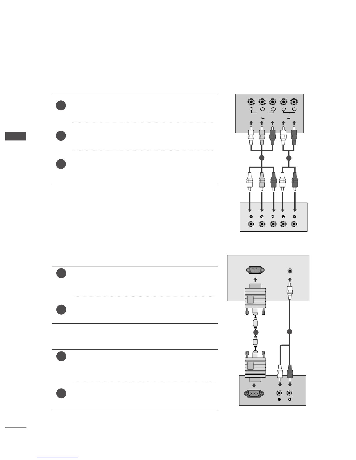
Connect the SET TOP with the D-Sub output socket to
RR GGBB (( PPCC// DDTT VV )) IINN
socket on the set and audio cable of
the SET TOP to the
AAUUDD II OO ((RRGGBB //DD VV II)) IINN
.
Press the
II NNPP UUTT
button to select RGB (DTV).
Connect the SET TOP with the D-Sub output socket to
RR GG BB
((PPCC//DDTTVV)) IINN
socket on the set and audio cable of the SET
TOP to the
AAUUDD IIOO ((RRGG BB )) IINN
.
Press the
II NNPPUUTT
button to select RGB (DTV).
Connect the SET TOP outputs to the
CCOOMMPPOONNEENN TT IINN
VV IIDDEE OO
sockets (YP
B P
R
) on the set.
Connect the audio cable from the SET TOP to
CCOOMMPPOO--
NNEE NNTT IINN AAUUDD II OO
sockets of the set.
Press the
II NN PP UU TT
button to select Component
(480i/576i/480p/576p/720p/1080i).
2
3
1
16
EXTERNAL EQUIPMENT SETUP
EXTERNAL EQUIPMENT SETUP
HD RECEIVER SETUP
■
To prevent the equipment damage, never plug in any power cords until you have finished connecting all equipment.
■
Here shown may be somewhat different from your TV.
When connecting with a component cable (Only 19/22LS4R*)
Y
PBPRLR
VIDEO
COMPONENT IN
AUDIO
RGB OUTPUT
RGB (PC/DTV) IN
AUDIO
(RGB/DVI) IN
1
2
2
1
When connecting with a D-sub 15 pin cable
19/22LS4R
*
17LS5R
*
1
2
2
1
Ofrecido por www.electromanuales.com
17
EXTERNAL EQUIPMENT SETUP
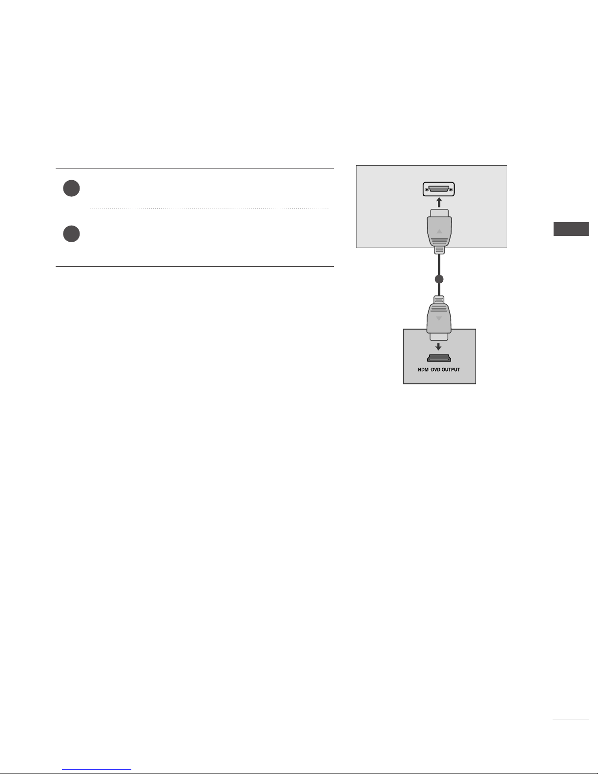
When connecting with a HDMI(Only 19/22LS4R*)
Connect the HDMI output of the digital set-top box to the
HH DDMM II //DDVV II IINN
jack on the set.
Select HDMI/DVI (DTV) input source with using the
II NNPPUUTT
button on the remote control.
2
1
HDMI/DVI IN
1
Ofrecido por www.electromanuales.com
18
EXTERNAL EQUIPMENT SETUP
DVD SETUP
EXTERNAL EQUIPMENT SETUP
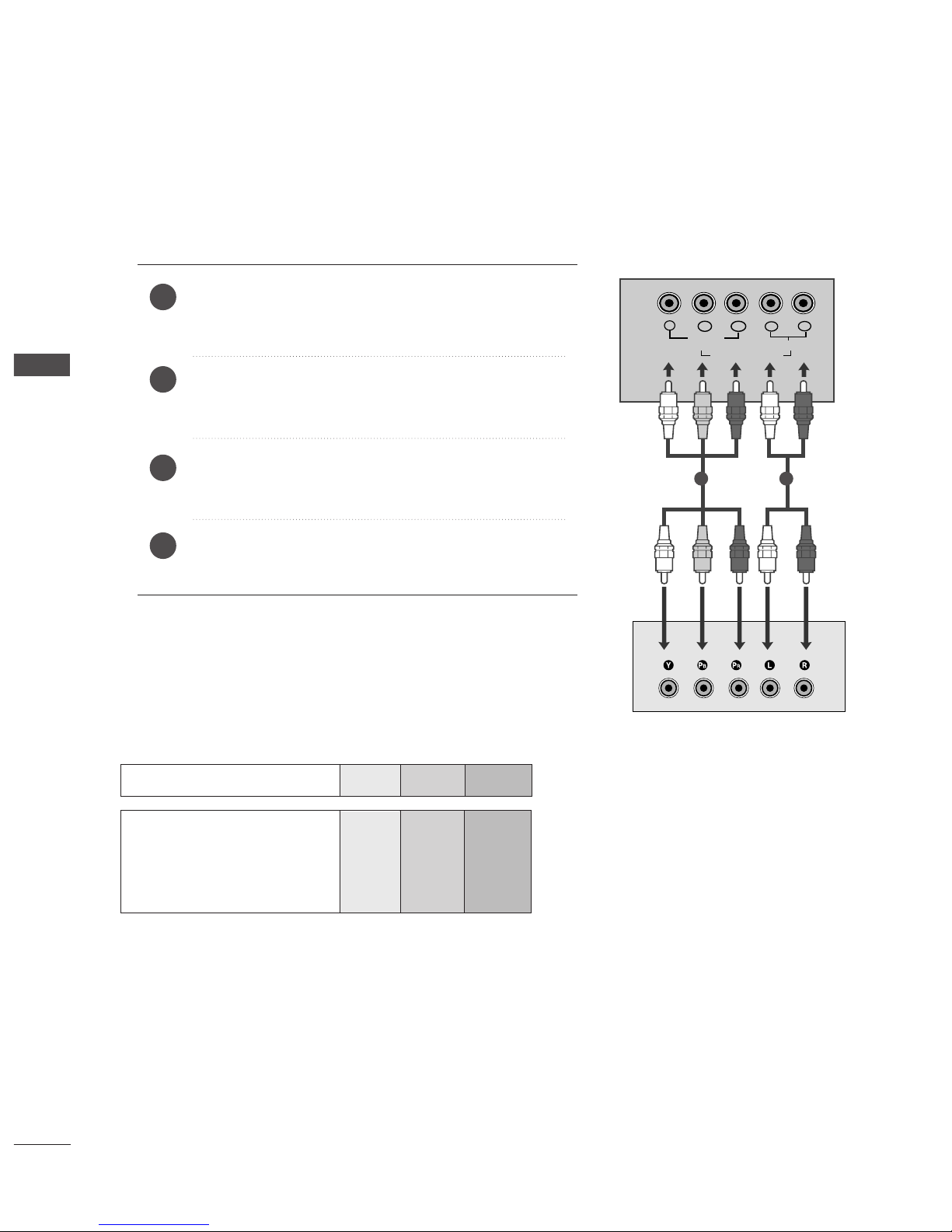
When connecting with a component cable (Only 19/22LS4R*)
Y
PBPRLR
VIDEO
COMPONENT IN
AUDIO
Component Input ports
To get better picture quality, connect a DVD player to the component input ports as shown below.
Component ports on the TV
YPB PR
Video output ports
on DVD player
Y
Y
Y
Y
P
B
B-Y
Cb
Pb
P
R
R-Y
Cr
Pr
Connect the video output sockets (Y Cb Cr, Y Pb Pr, Y B-Y
R-Y or YP
B
PR
) of the DVD to the
CCOOMMPPOONN EE NNTT IINN
VV IIDDEEOO
sockets (YP
B
PR
) of the set.
Connect the audio cable from the DVD to
CCOOMMPP OONN EENNTT
II NN AAUUDD IIOO
sockets of the set.
Press the
II NN PP UU TT
button to select
Component
(480i/576i/480p/576p/720p/1080i).
Press the
PP LL AAYY
button on the DVD.
The DVD playback picture appears on the screen.
2
3
4
1
1 2
Ofrecido por www.electromanuales.com
HDMI/DVI IN
AV 1
(R) AUDIO (L)
AUDIO/
VIDEO
19
EXTERNAL EQUIPMENT SETUP
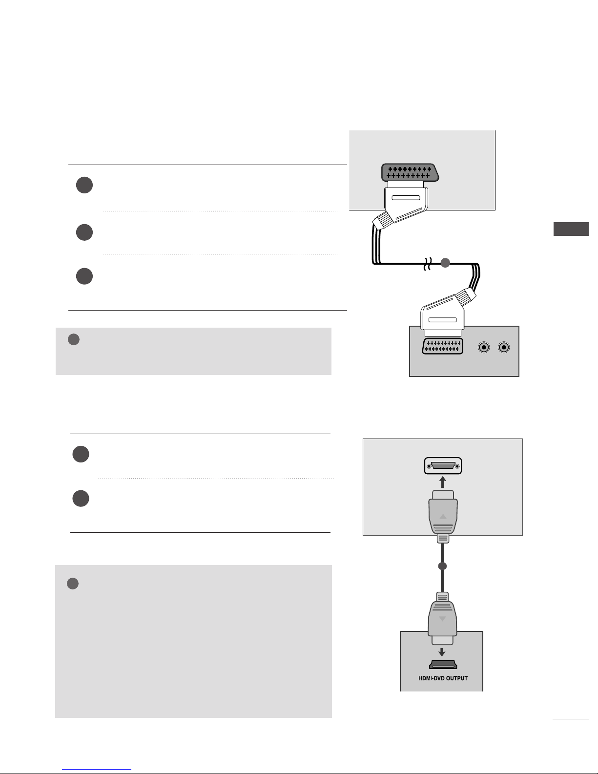
When connecting with a Euro Scart
Connect the Euro scart socket of the DVD to the Euro scart
socket of the set.
Press the
II NNPPUUTT
button to select
AV 1.
Press the
PP LL AAYY
button on the DVD.
The DVD playback picture appears on the screen.
2
3
1
1
NOTE
!
GG
Please use the shield scart cable.
When connecting HDMI cable(Only 19/22LS4R*)
Connect the HDMI output of the DVD to the
HH DDMM II //DDVV II IINN
jack on the set.
Select HDMI/DVI (DTV) input source with using
the
II NNPPUUTT
button on the remote control.
2
1
1
GG
TV can receive the video and audio signal simultaneously
with using a HDMI cable.
GG
If the DVD supports Auto HDMI function, the output resolution of the source device will be automatically set to
1280x720p.
GG
If the DVD player does not support Auto HDMI, you need to
set the DVD output resolution appropriately.
To get the best picture quality, adjust the output resolution
of the source device to 1280x720p.
NOTE
!
Ofrecido por www.electromanuales.com
20
VCR SETUP
EXTERNAL EQUIPMENT SETUP
EXTERNAL EQUIPMENT SETUP
■
To avoid picture noise (interference), leave an adequate distance between the VCR and TV.
■
Typically a frozen still picture from a VCR. If the 4:3 picture format is used; the fixed images on the sides of
the screen may remain visible on the screen.
OUTPUT
SWITCH
ANT IN
R
S-VIDEO VIDEO
ANT OUT
L
ANTENNA IN
Wall Jack
Antenna
1
2
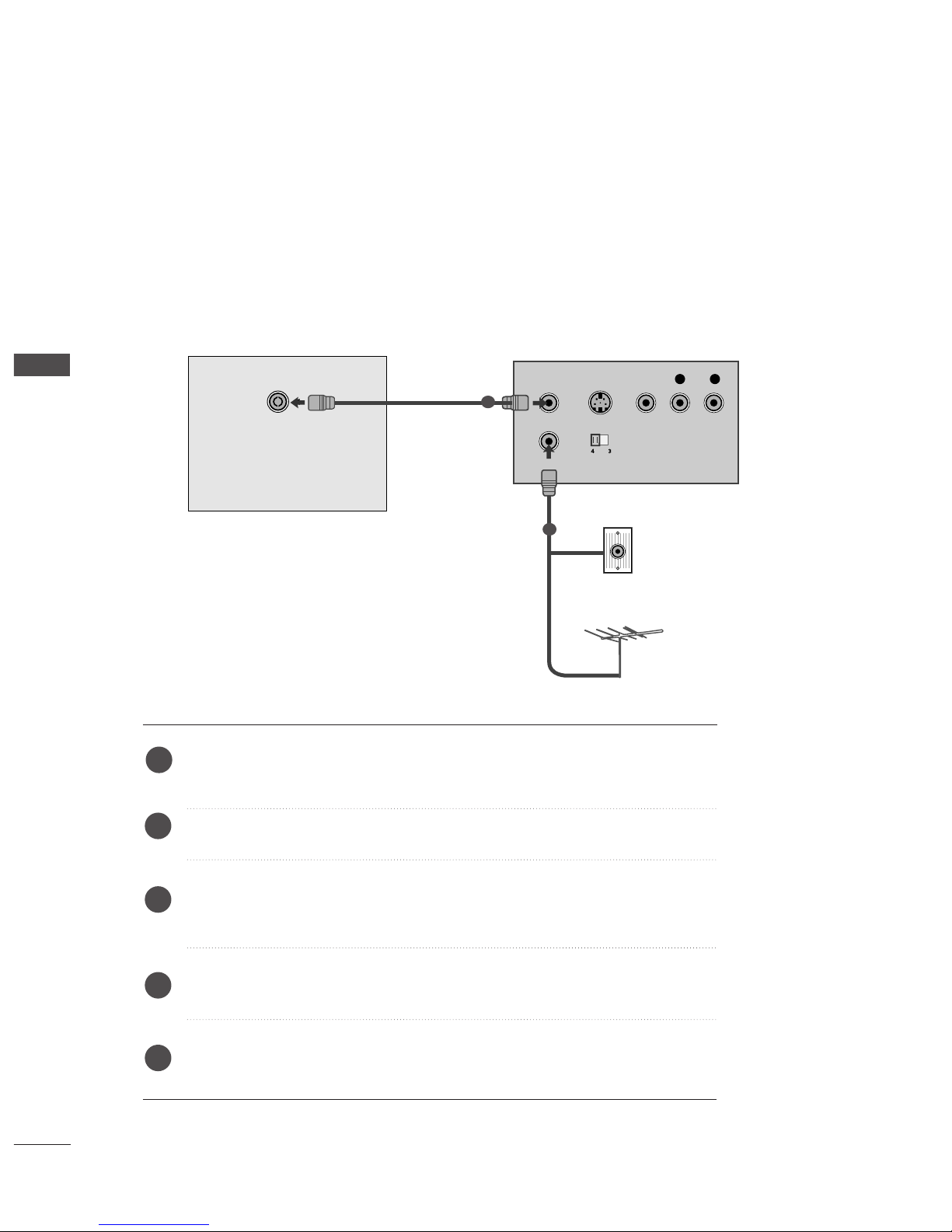
When connecting with an antenna
Connect the RF out socket of the VCR to the aerial socket of the set.
Connect the aerial cable to the RF aerial in socket of the VCR.
Store the VCR channel on a desired programme number using the ‘Manual
programme tuning’ section.
Select the programme number where the VCR channel is stored.
Press the
PP LLAAYY
button on the VCR.
1
2
3
4
5
Ofrecido por www.electromanuales.com
 Loading...