

LG 24BK55WY, 24BK55WD, 22BK55WY, 22BK55WD User Manual

ENGLISH
OWNER’S MANUAL
IPS LED MONITOR
(LED LCD MONITOR)
Please read this manual carefully before operating
your set and retain it for future reference.
IPS LED(LED LCD) MONITOR MODEL
22BK55WD
24BK55WD
22BK55WY
24BK55WY
www.lg.com

TABLE OF CONTENTS
2
ENGLISH
ENG
CONTENTS
3 ASSEMBLING AND PREPAR-
ING
3 Unpacking
4 Parts and buttons
6 Setting up the Monitor set
6 - Attaching the Stand Base
6 - Detaching the stand base
7 - Detaching the stand body
7 - Using the cable holder
7 - Mounting on a table
8 - Adjusting the angle
9 - Adjusting the stand height
9 - Using the Kensington locking device
10 - Swivel stand
10 - Using the Pivot function
11 - Mounting on a wall
23 TROUBLESHOOTING
25 SPECIFICATIONS
25 22BK55WY
26 22BK55WD
27 24BK55WY
28 24BK55WD
29 Preset Modes (Resolution)
30 Indicator
31 PROPER POSTURE
31 Proper posture for using the Monitor set.
12 USING THE MONITOR SET
12 Connecting to a PC
12 - D-SUB connection
12 - DVI-D connection
14 - Peripheral device connection
15 CUSTOMIZING SETTINGS
16 Customizing Settings
16 - Menu Settings
17 - Picture
18 - Color
19 - Display
19 - Audio
20 - Others
21 - READER Setting
22 - SMART ENERGY SAVING Setting
ASSEMBLING AND PREPARING
3
ASSEMBLING AND PREPARING
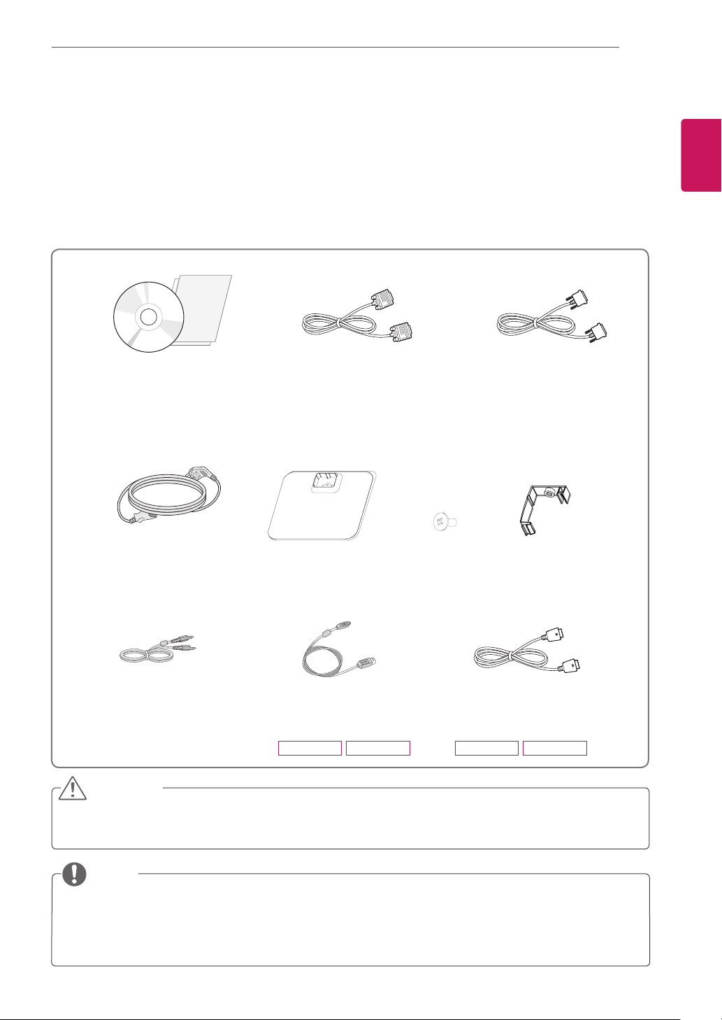
Unpacking
Check your product box for the following items. If there are any missing accessories, contact the local
dealer where you purchased your product. The illustrations in this manual may differ from the actual product
and accessories.
CD(Owner's Manual) /
Card
D-SUB Cable
(This cable is not included in all
countries.)
(This cable is not included in all
DVI-D Cable
countries.)
ENGLISH
ENG
Power Cord
Audio Cable
( Depending on the country )
Stand Base
USB Cable
( Depending on the country )
22BK55WY 24BK55WY 22BK55WY 24BK55WY
One Screw
Display Port Cable
(This cable is not included
in all countries.)
Cable Holder
CAUTION
Do not use any unapproved accessories to ensure the safety and product life span.
y
Any damages or injuries by using unapproved accessories are not covered by the warranty.
y
NOTE
The accessories supplied with your product may vary depending on the model.
y
Product specifications or contents in this manual may be changed without prior notice due to upgrade
y
of product functions.
ENGLISH
ENG
ASSEMBLING AND PREPARING
4
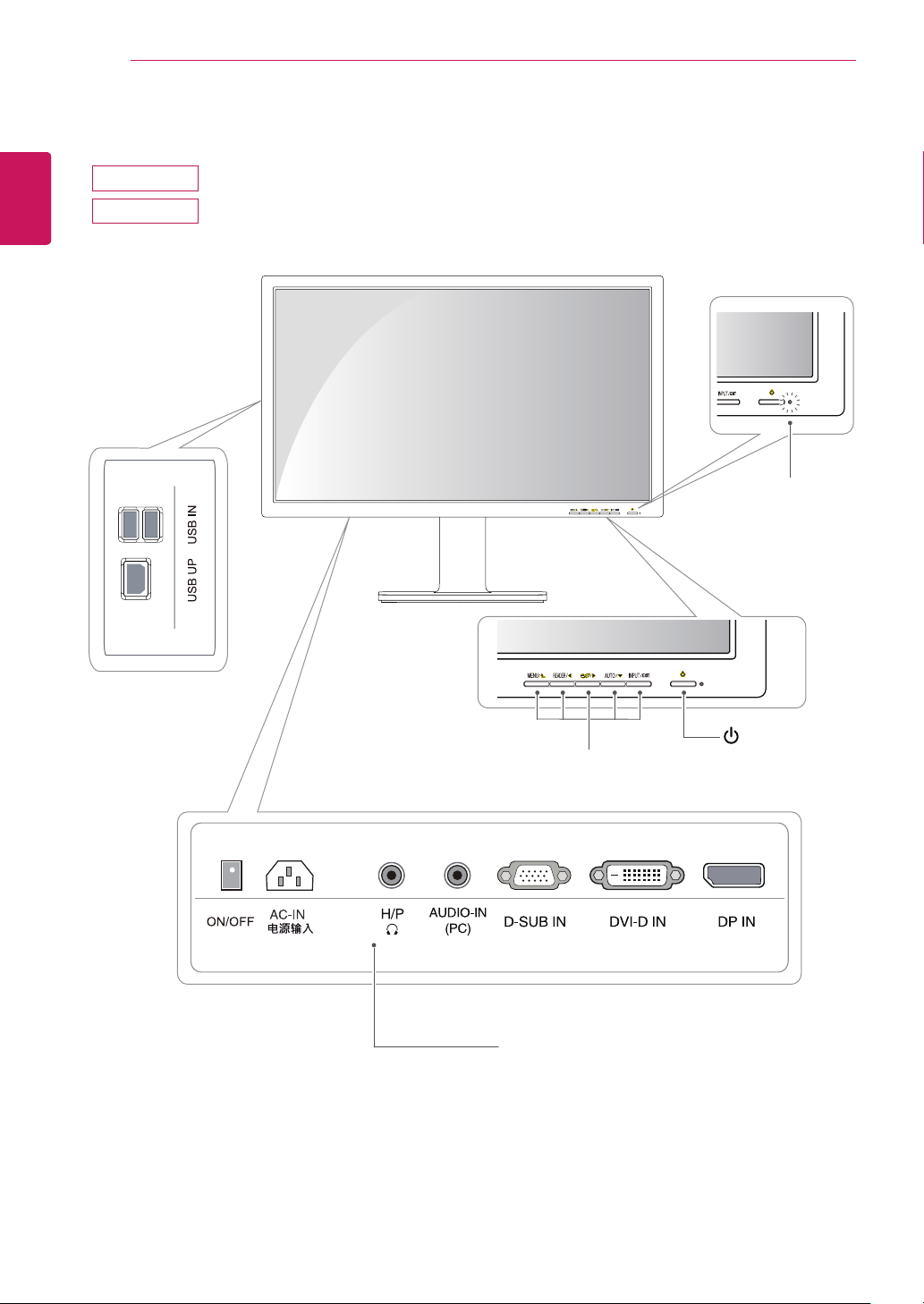
Parts and buttons
22BK55WY
24BK55WY
Power Indicator
LED On : Power is on
y
LED Off: Power is off
y
Front Side Buttons
Input Connectors (See p.12 to 14)See p.12 to 14) to 14)14))
(Power Button)
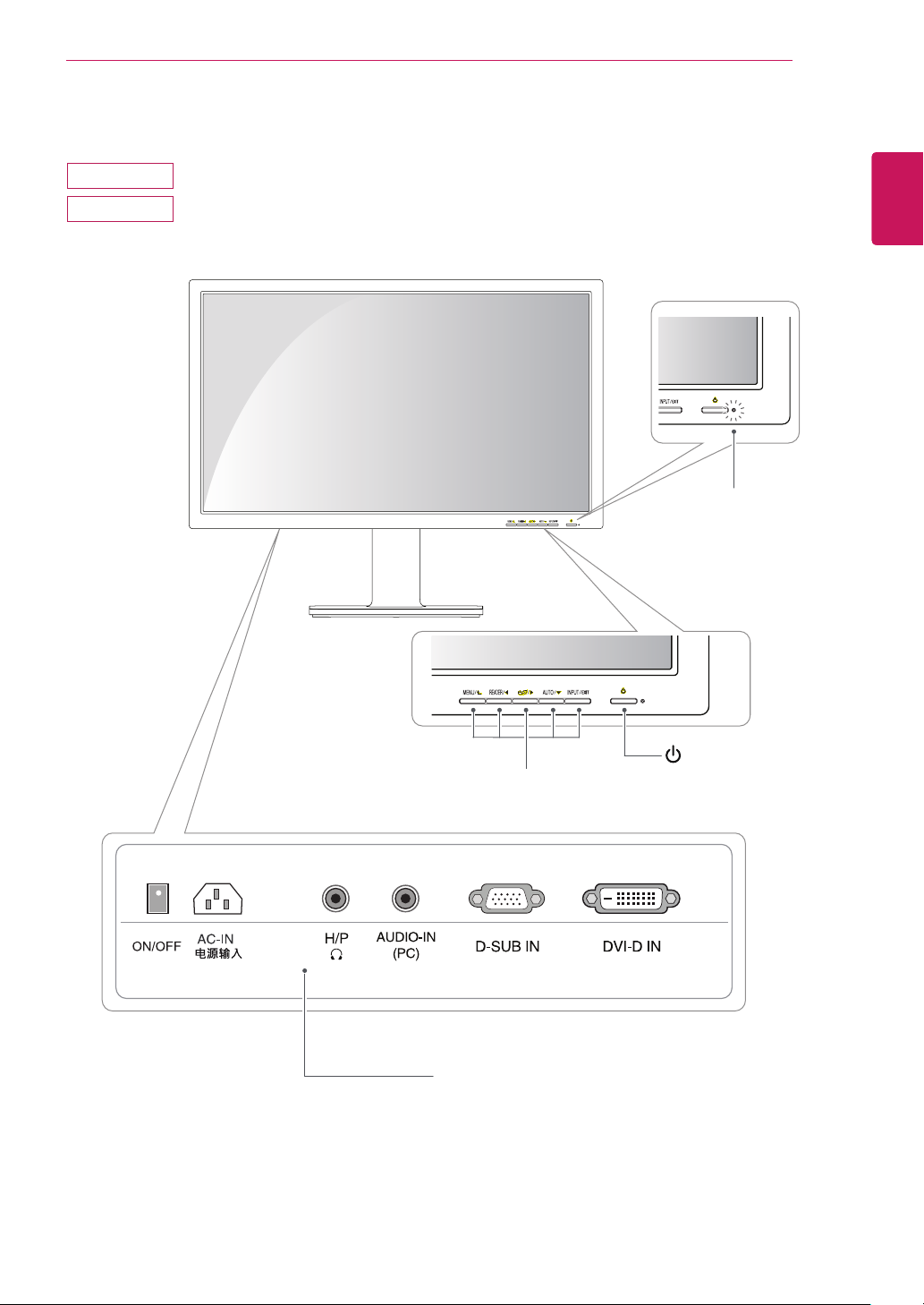
22BK55WD
24BK55WD
ASSEMBLING AND PREPARING
Power Indicator
LED On : Power is on
y
LED Off: Power is off
y
5
ENGLISH
ENG
Front Side Buttons
Input Connectors (See p.12 to 14)See p.12 to 14) to 14)14))
(Power Button)
ASSEMBLING AND PREPARING
6
ENGLISH
ENG
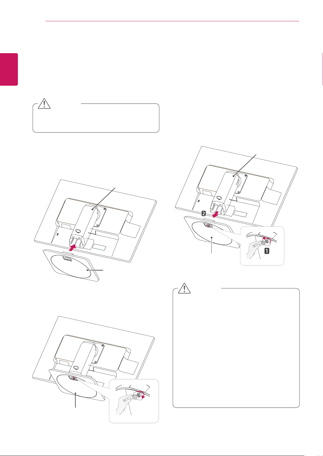
Setting up the Monitor set
Attaching the Stand Base
Place the Monitor set with the screen side
1
down on a flat and cushioned surface.
CAUTION
To protect the screen from scratches, cover
y
the surface with a soft cloth.
Check the
2
the stand body, then mount the
the
position (at the front and rear)
stand body
as shown in the figure.
Stand Body
stand base
of
on
Detaching the stand base
Place the monitor's screen face down.
1
To protect the screen from scratches, cover the
surface with a soft cloth.
Using a coin, turn the screw in the stand base
2
counterclockwise. Detach the
stand body
the
.
stand base
Stand Body
from
Using a coin, turn the screw clockwise to se-
3
cure the
stand base.
Stand Base
Stand Base
Stand Base
CAUTION
The components appearing in the illustra-
y
tions may look different from the actual product.
Do not carry the monitor upside-down as this
y
may cause it to fall off its stand, resulting in
damage or injury.
To avoid damaging the screen when lifting
y
or moving the monitor, only hold the stand or
the plastic cover. This avoids putting unnecessary pressure on the screen.
Only remove the tape and the locking pin
y
when the monitor is mounted on the stand
base and is in an upright position. Otherwise,
the stand body may protrude, which may
lead to injury.
ASSEMBLING AND PREPARING
7
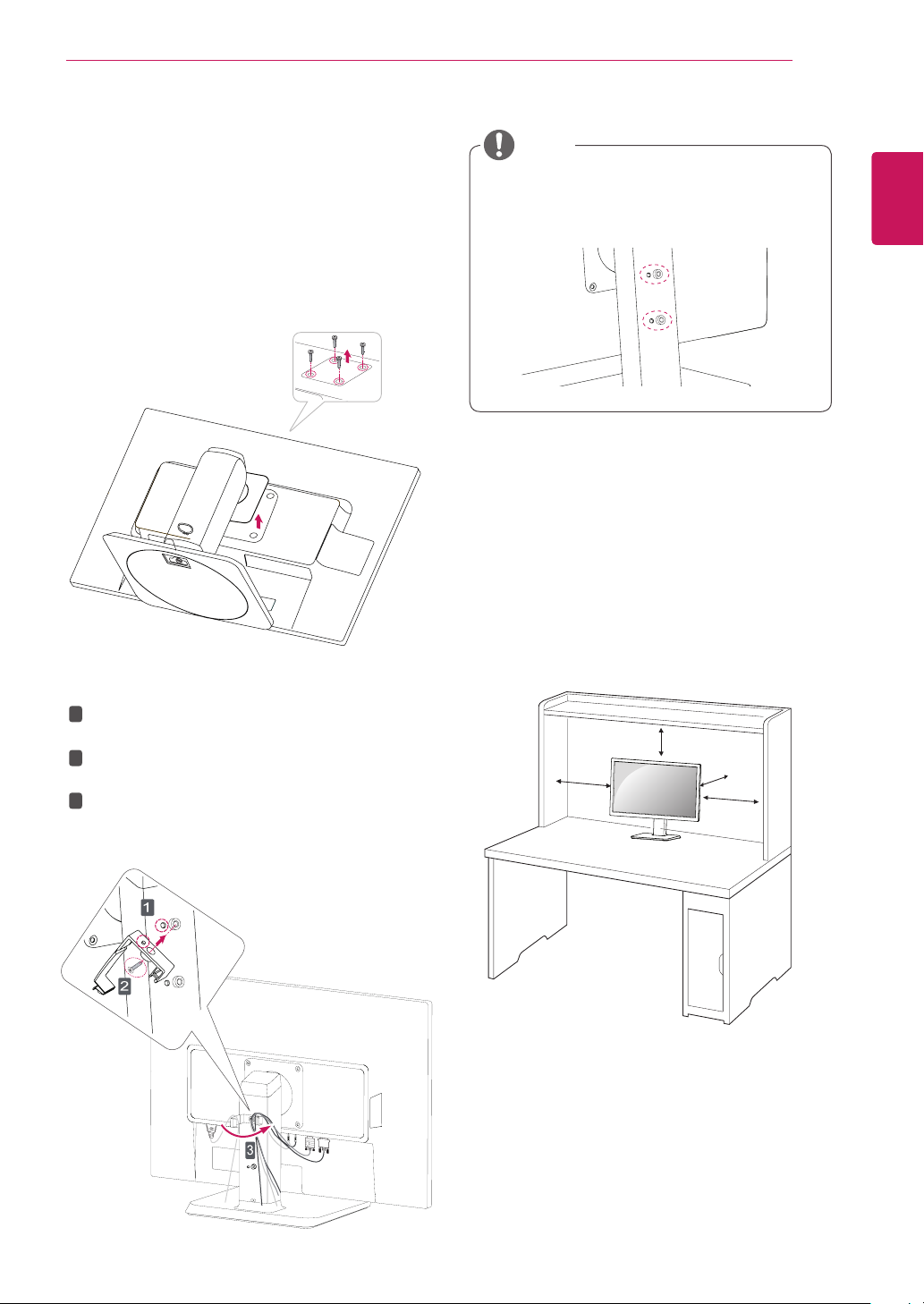
Detaching the stand body
Place the monitor's screen face down. To
1
protect the screen from scratches, cover the
surface with a soft cloth.
Using a screwdriver, remove the four screws
2
and detach the stand from the monitor.
Using the cable holder
1
Fix the Knob (Cable holder) to the
Hole(Hingebody).
Use one screw to fix the Cable Holder and
2
monitor set.
3
Close the Cable holder.
NOTE
The holes are used for wall mount bracket.
y
Varies depending upon your country or
y
model.
Mounting on a table
Lift the monitor and place it on the table in an
1
upright position.
100 mm
100 mm
100 mm
away from the wall to
100 mm
100 mm
Install at least
ensure sufficient ventilation.
ENGLISH
ENG
ASSEMBLING AND PREPARING
8
ENGLISH
ENG
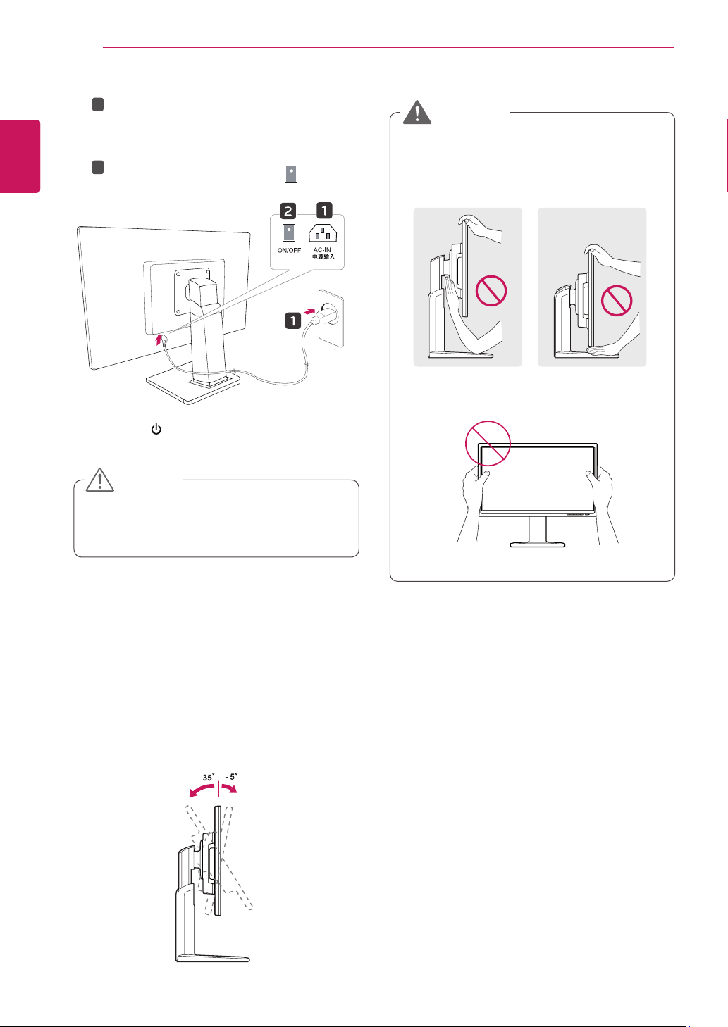
2
3
Connect the Power cord to the monitor, then
1
plug the power cord into the wall outlet.
(Before connect please check the “ON/OFF”
knob in “O” state).
2
Press the “ON/OFF” knob in “ ” state
(Open the power).
Press the (Power) button on the front of the
monitor to turn on the monitor.
CAUTION
Unplug the power cord prior to moving or
y
installing the monitor. There is risk of electric
shock.
WARNING
To avoid injury to the fingers when adjusting
y
the screen, do not hold the lower part of the
monitor's frame as illustrated below.
Be careful not to touch or press the screen
y
area when adjusting the angle of the monitor.
Adjusting the angle
Place the monitor mounted on the stand base
1
in an upright position.
Adjust the angle of the screen. The angle of
2
the screen can be adjusted up to 5° forwards
and 35° backwards for a comfortable viewing
experience.
Front SideRear Side
ASSEMBLING AND PREPARING
9
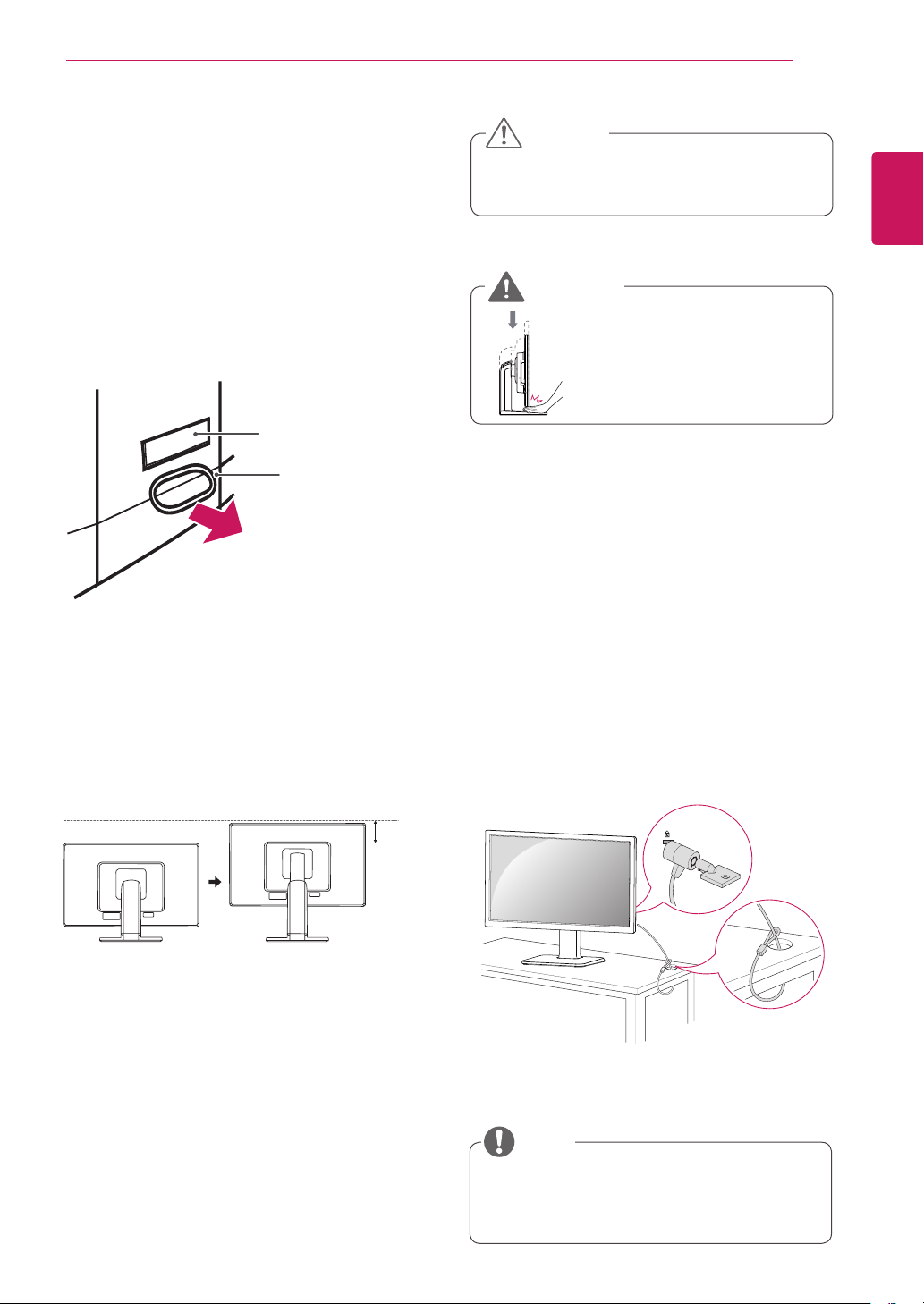
Adjusting the stand height
Place the monitor mounted on the stand base
1
in an upright position.
Remove the tape attached at the bottom rear
2
of the stand body, then pull out the locking
pin.
Stand Body
Tape
Locking Pin
CAUTION
Once the pin is removed, it is not necessary
y
to re-insert it to adjust the height.
WARNING
Do not put your finger be-
y
tween the screen and the
base (chassis) when adjusting the screen's height.
Using the Kensington locking device
The connector for the Kensington lock is located
on the rear of the monitor.
For more information on installation and usage,
refer to the Kensington lock user manual or visit
the website at http://www.kensington.com.
ENGLISH
ENG
The height can be adjusted up to
3
130 mm.
130.0mm
Connect the monitor to the table with the Kensing-
ton lock cable.
NOTE
Using the Kensington lock is optional. The
y
accessories can be purchased at your local
electronics store.
ENGLISH
ENG
ASSEMBLING AND PREPARING
10
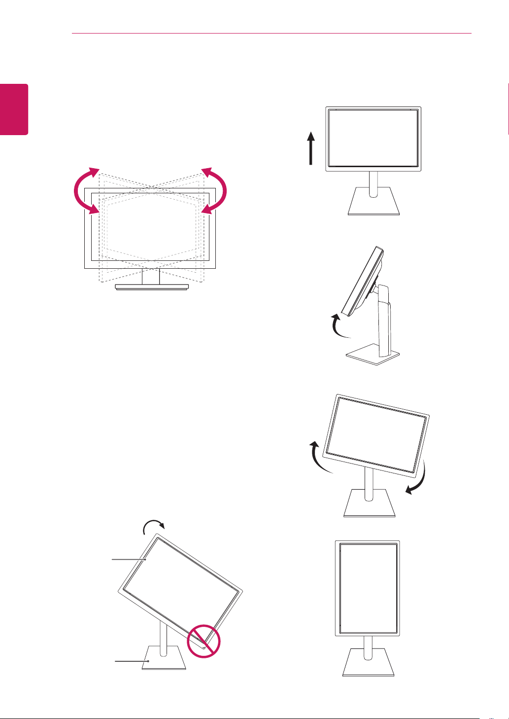
Swivel stand
Image shown may differ from your Monitor
y
set.
Swivel 355 degrees and adjust the angle of the
1
Monitor set to suit your view.
Be careful with the cables when rotating the
3
screen.
Using the Pivot function
The pivot function allows you to rotate the screen
90 degrees clockwise.
Lift the monitor to its highest height to utilize
1
the Pivot function.
Landscape & Portrait : You can rotate the panel
2
90° clockwise. Please be cautious and avoid
contact between the monitor head and the
Stand Base when rotating the screen to access
the Pivot function. If the monitor head touches
the Stand Base, then the Stand Base could
crack.
Head
section
Stand
section
 Loading...