

Page 1

Please read this manual carefully before operating your set and
0197
0123
retain it for future reference.
17HK701G-W
OWNER’S MANUAL
Flat Panel Digital X-ray
Detector
Printed in Korea
www.lg.com
Copyright 2017 LG Electronics Inc. All Rights Reserved.
Page 2
Please note that this information is for proper use and safety of the equipment. The following symbols may
indicate a hazardous situation in which, if not needed, may result in serious injury or even death to the user
or others, or damage to the equipment.
ENGLISH
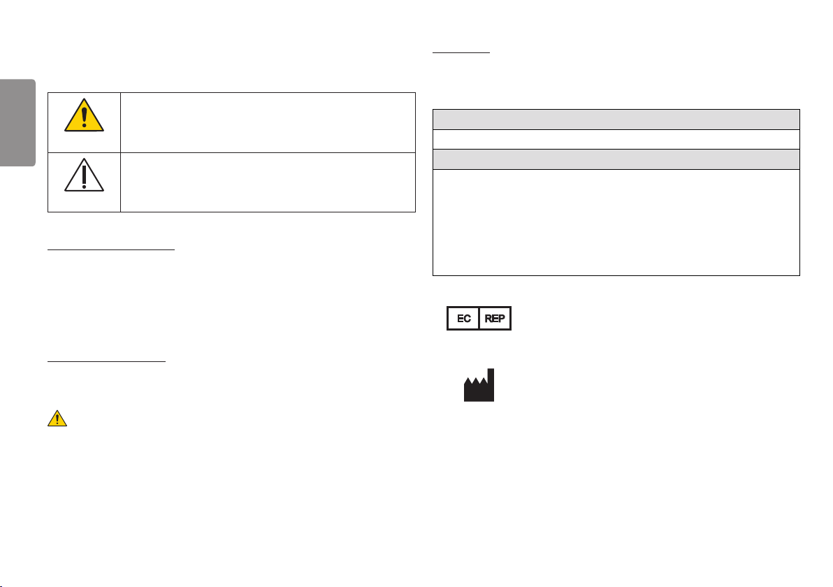
Indicates warning and safety instructions. If not adhered to, it could result in death
or serious injury to the user or others.
WARNING
Indicates a hazardous situation which, if not heeded, may result in minor or
moderate injury to the user or others, or damage to the equipment.
CAUTION
For users in the United States
• United State federal law restricts this equipment to be used by or on the order of a physician.
• Since the X-ray exposure condition can be changed depending on the age, gender and bone density of
the patient, in case of Pediatric, X-ray exposure condition can be changed by expert’s judge. For further
information, please refer to FDA Pediatric X-ray Imaging webpage. http://www.fda.gov/radiationemittingproducts/radiationemittingproductsandprocedures/medicalimaging/ucm298899.htm
For users in other countries
• This equipment is to be used by or on the order of a licensed person under the related laws for each
country.
WARNING
• To avoid the risk of electric shock, this equipment must only be connected to a supply mains with
protective earth.
• Do not modify this equipment without authorization of the manufacturer.
Intended use
• The Flat Panel Digital X-ray Detector 17HK701G-W is indicated for digital imaging solution designed
for general radiographic system for human anatomy. It is intended to replace film or screen based
radiographic systems in all general purpose diagnostic procedures. Not to be used for mammography.
Target Population
• No limitation
Target Disease and Target Area
• Bone fractures and breaks
• Scoliosis (abnormal curvature of the spine)
• Non-cancerous and cancerous bone tumors
• Lung problems, such as pneumonia and lung cancer
• Heart problems, such as heart failure
• Breast cancer
Authorized representative in the European community.
EC REP
LG Electronics European Shared Service Center B.V.
Krijgsman 1, 1186 DM Amstelveen, The Netherlands
Tel : +31-20-456-3132
LG Electronics Inc.
77, Sanho-daero, Gumi-si, Gyeongsangbuk-do, 39381, Republic of Korea
Tel : +82-1544-8777
2
Page 3
SAFETY PRECAUTION
Please read these safety precautions carefully before using the product.
WARNING
• Do not leave any material that may cause fire in the vicinity of the detector.
• Please clean foreign material using dry cloth.
• Using any adapter or cable other than those provided with the product may result in malfunction.
• Unauthorized disassembly or reassembly of the product may result in electric shock or malfunction of the
product.
• Be careful when handling the detector. Do not drop or knock the product.
• If the product emits smoke or strange odors during use, turn off the power immediately and remove the
plug.
• For your safety, when cleaning the detector, turn off the detector and unplug the power cable.
• If the product is defective, do not attempt to repair it yourself. Instead, contact the Supplier
• Always use the detector on a flat surface to prevent bending or damage.
• Make sure that the connecting parts of the detector are out of reach of patients.
• Do not apply excessive weight to the detector.
- The detector may be damaged if the entire surface of the detector is subjected to a weight of 150 kg
or more.
- The detector may be damaged if the center of the detector is subjected to a weight of 100 kg or more.
CAUTION
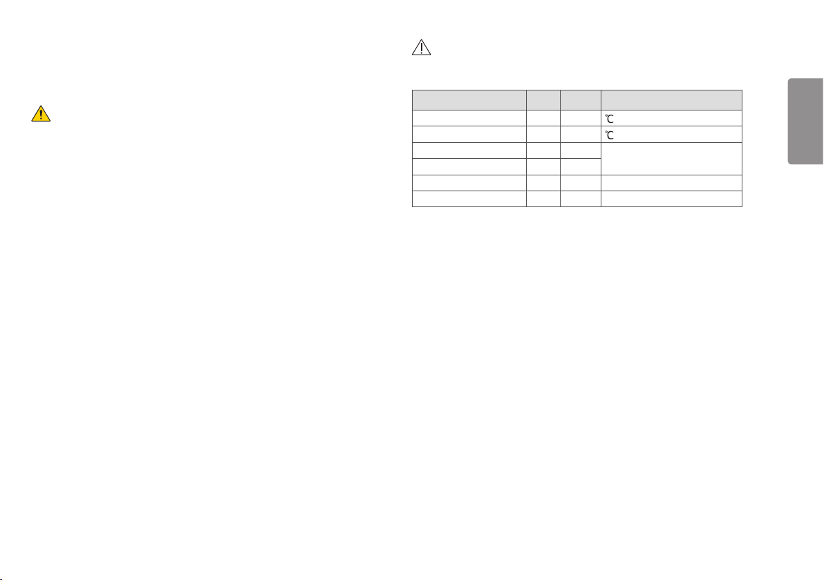
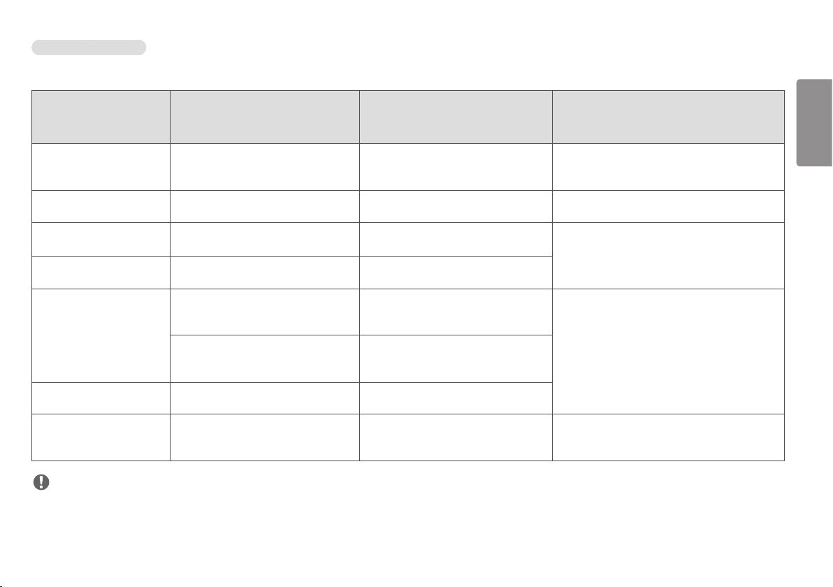
• Always use the detector in places that meet the following environmental requirements.
Item Min. Max Units
Temperature (Storage) -20 60
Temperature (Operation) 10 35
Humidity (Storage) 0 90 %, Non-condensing, Relative Humidity
Humidity (Operation) 0 80
Pressure (Storage) 50 106 kPa
Pressure (Operation) 70 106 kPa
• Do not use the detector in the following places:
- Places that are damp or in direct sunlight
- Dusty places
- Hot and humid places
- Frozen places
- Unstable places, such as those subject to severe vibrations or noise
- Places with devices that generate a strong magnetic field
- Any other place that may compromise the lifespan or performance of the detector
• Do not spray detergents, etc. onto the detector. Always wear gloves when cleaning the detector
ENGLISH
3
Page 4

Precautions for Using the AC adapter
Precautions for Using the Battery
Do not use the AC adapter when it is in an excessively bent position.
If the AC adapter cable is used for long periods while bent, it could cause internal wiring to become severed
ENGLISH
and cause electrical shocks or start a fire.
Integrated Adapter
This product can be battery-powered. When you are using this product for the first time after purchase,
install batteries in the product and plug it into power to charge the batteries.
• The battery is a consumable component. Its usable capacity reduces gradually over long-term use.
• For battery replacement, please make sure to contact the designated manufacturer.
• Please refer to the manual for instructions on how to remove and replace the battery.
• Always use batteries approved and certified by manufacturer.
- Failure to do so may cause a fire or explosion.
• Do not store the product in an enclosed space (bags, etc.) with the power on repeatedly or for long
periods.
- Overheated batteries may cause fire.
• Do not expose the product to flames.
- This may result in explosion or fire.
• Keep the product away from metallic objects, such as car keys and paper clips, when storing or moving.
- Excess current may cause a rapid temperature increase, resulting in fire or burns.
• Contact the manufacturer if the battery leaks or emits an odor.
- Otherwise, it may cause explosion or fire.
• Do not recharge the product using a power supply or circuit other than the one supplied with the product.
- This may damage the battery or cause a fire
4
Page 5
SAFETY INFORMATION
Regulations
Safety Standard
Medical Device Classification
equipment
Classification by protection type
against Electric Shock
Classification according to the degree
of protection against ingress of water
or particulate matter
Mode of operation
Environment of Use
Applied Part
NOTE
• Additional equipment connected to medical electrical equipment must comply with the respective IEC or
ISO standards (e.g. IEC 60950-1 for data processing equipment).
• Furthermore all configurations shall comply with the requirements for medical electrical systems (see
clause 16 of the 3.1Ed. of IEC 60601-1, respectively).
• Anybody connecting additional equipment to medical electrical equipment configures a medical system
and is therefore responsible that the system complies with the requirements for medical electrical
systems.
• Attention is drawn to the fact that local laws take priority over the above mentioned requirements.
• If in doubt, consult manufacturer.
Class
IP41 (Rating for when the main cable is not attached)
Continuous Operation
This equipment is not suitable for use in the presence of
flammable anesthetic or oxygen.
Type : BF Type, Location : Front of Detector (only for
effective area)
Safety and Electromagnetic Compatibility Information
This equipment has been tested and found to comply with the limits for
medical devices in IEC 60601-1-2. These limits are designed to provide
reasonable protection against harmful interference in a typical medical
installation.
This device complies with part 15 of the FCC Rules. Operation is subject to the
following two conditions: (1) This device may not cause harmful interference,
and (2) this device must accept any interference received, including
interference that may cause undesired operation.
Note : This equipment has been tested and found to comply with the limits for
a Class A digital device, pursuant to part 15 of the FCC Rules. These limits are
designed to provide reasonable protection against harmful interference when
the equipment is operated in a commercial environment.
This equipment generates, uses and can radiate radio frequency energy and, if
not installed and used in accordance with the instructions manual, may cause
harmful interference to radio communications.
Operation of this equipment in a residential area is likely to cause harmful
interference in which case the user will be required to correct the interference
at his own expense.
Changes or modifications not expressly approved by the party responsible for
compliance could void the user's authority to operate the equipment.
This device comply with RF exposure requirements.
ENGLISH
5
Page 6
Canadian Compliance
This radio transmitter has been approved by Industry Canada to operate with the antenna types listed below with
the maximum permissible gain and required antenna impedance for each antenna type indicated. Antenna
ENGLISH
types not included in this list,having a gain greater than the maximum gain indicated for that type, are strictly
prohibited for use with this device.
Under Industry Canada regulations, this radio transmitter may only operate using an antenna of a type and
maximum(or lesser) gain approved for the transmitter by Industry Canada. To reduce potential radio interference
to other users, the antenna type and its gain should be so chosen that the equivalent isotropically radiated power
(e.i.r.p) is not more than that necessary for successful communication.
This device complies with Industry Canada license-exempt RSS standard(s).
Operation is subject to the following two conditions:
(1)(1) this de e may not cause interference, and (2) this device must accept any interference, including
interference that may cause undesired operation of the device.
Le présent émetteur radio a été approuvé par Industrie Canada pour fonctionner avec les types d'antenne
énumérés ci-dessous et ayant un gain admissible maximal et l'impédance requise pour chaque type d'antenne.
Les types d'antenne non inclus dans cette liste, ou dont le gain est supérieur au gain maximal indiqué, sont
strictement interdits pour l'exploitation de l'émetteur.
Conformément à la réglementation d'Industrie Canada, le présent émetteur radio peut fonctionner avec une
antenne d'un type et d'un gain maximal (ou inférieur) approuvé pour l'émetteur par Industrie Canada. Dans le
but de réduire les risques de brouillage radioélectrique à l'intention des autres utilisateurs, il faut choisir le type
d'antenne et son gain de sorte que la puissance isotrope rayonnée équivalente (p.i.r.e.) ne dépasse pas l'intensité
nécessaire à l'établissement d'une communication satisfaisante.
Le présent appareil est conforme aux CNR d'Industrie Canada applicables aux appareils radio exempts de licence.
L'exploitation est autorisée aux deux conditions suivantes :
(1)l'appareil ne doit pas produire de brouillage, et (2) l'utilisateur de l'appareil doit accepter tout brouillage
radioélectrique subi, même si le brouillage est susceptible d'en compromettre le fonctionnement.
This
device can be operated in at least one Member State without infringing applicable
requirements in the use of radio spectrum.
This device is compliant with the RED article 10.10 requirement because the information is
available on the package. (This device is restricted to indoor use only within the 5.15 ~ 5.35GHz
Band.)
Electro-Magnetic Compatibility Information
Electro-Magnetic Emissions
This EUT is intended for use in the electromagnetic environment specified below.
The customer or the user of the EUT should assure that it is used in such an environment.
Immunity Test Compliance
RF Emissions CISPR 11 Group 1 The EUT uses RF energy only for its internal
RF Emissions CISPR 11 Class A The EUT is suitable for use in all
Harmonic emissions IEC
A
61000-3-2
Voltage fluctuations/ Flicker
Complies
emissions
IEC 61000-3-3
Electromagnetic Environment –
Guidance
function.
Therefore, its RF emissions are very low and
are not likely to cause any interference in
nearby electronic equipment.
establishments, including domestic
establishments and those directly connected
to the public low-voltage power supply
network that supplies buildings used for
domestic purposes.
6
Page 7
Electro-Magnetic Immunity
This EUT is intended for use in the electromagnetic environment specified below. The customer or the user of the EUT should assure that it is used in such an environment.
Immunity Test
IEC 60601-1-2
Test Level
Compliance
Level
Electromagnetic Environment – Guidance
ENGLISH
Electrostatic discharge (ESD)
IEC 61000-4-2
Electrical fast transient/burst
IEC 61000-4-4
Surge Line-to-line
IEC 61000-4-5
Surge Line-to-ground
IEC 61000-4-5
Voltage dips
IEC 61000-4-11
Voltage interruptions
IEC 61000-4-11
RATED power frequency
magnetic fields (50/60Hz)
IEC 61000-4-8
± 8 kV contact
± 2 kV, ± 4 kV, ± 8 kV, ± 15 kV air
± 2 kV
100 kHz repetition frequency
± 0,5 kV, ± 1 kV ± 1 kV Mains power quality should be that of a typical
± 0,5 kV, ± 1 kV, ± 2 kV ± 2 kV
0 % UT; 0,5 cycle
At 0°, 45°, 90°, 135°, 180°, 225°, 270° and 315°
0 % UT; 1 cycle
and 70 % UT; 25/30 cycles
Single phase: at 0°
0 % UT; 250/300 cycle 0 % UT; 250/300 cycle
30 A/m 30 A/m Power frequency magnetic fields should be at
NOTE
• UT is THE A.C mains voltage prior to application of the test level.
± 8 kV contact
± 15 kV air
± 2 kV
100 kHz repetition frequency
0 % UT; 0,5 cycle
At 0°, 45°, 90°, 135°, 180°, 225°, 270° and 315°
0 % UT; 1 cycle
and 70 % UT; 25/30 cycles
Single phase: at 0°
Floors should be wood, concrete or ceramic tile. If
floors are covered with synthetic material, the relative
humidity should be at least 30%.
Mains power quality should be that of a typical
commercial or hospital environment.
commercial or hospital environment.
Mains power quality should be that of a typical
commercial or hospital environment. If the user of the EUT image
intensifier requires continued operation during power mains
interruptions, it is recommended that the EUT image intensifier
be powered from an uninterruptible power supply or a battery.
levels characteristic of a typical location in a typical
commercial or hospital environment.
7
Page 8
ENGLISH
Conducted
disturbances
induced by RF fields
IEC 61000-4-6
Radiated RF EM
fields
IEC 61000-4-3
Immunity Test
IEC 60601-1-2
Test Level
3 V
0,15 MHz – 80 MHz
6 V in ISM bands
between 0,15 MHz and
80 MHz
80 % AM at 1 kHz
3 V/m
80 MHz – 2,7 GHz
80 % AM at 1 kHz
Compliance
Level
3 V
0,15 MHz – 80 MHz
6 V in ISM bands
between 0,15 MHz and
80 MHz
80 % AM at 1 kHz
3 V/m
80 MHz – 2,7 GHz
80 % AM at 1 kHz
Electromagnetic Environment – Guidance
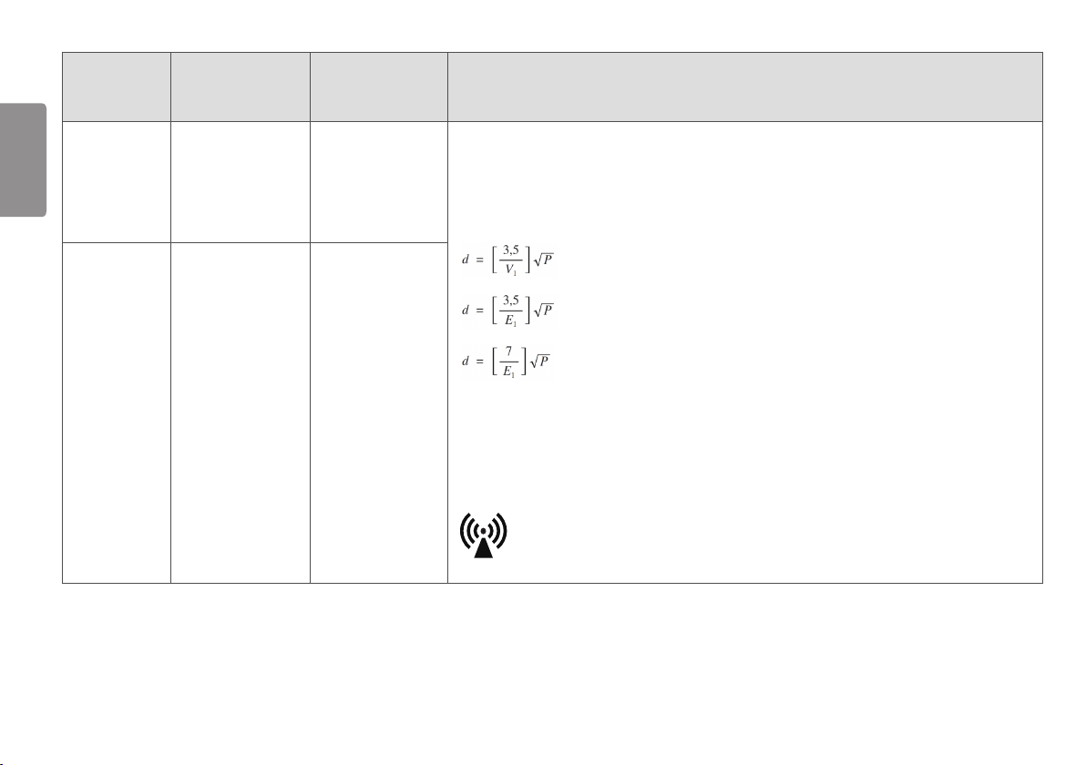
Portable and mobile RF communications equipment should be used no closer to any part of the EUT,
including cables, than the recommended separation distance calculated from the equation applicable to the frequency of the
transmitter.
Recommended separation distance:
80 MHz to 800MHz
800 MHz to 2.7GHz
Where P is the maximum output power rating of the transmitter in watts(W) according to the transmitter manufacturer and d is
the recommended separation distance in meters(M).
Field strengths from fixed RF transmitters as determined by an electromagnetic site survey, should be less than the compliance
level in each frequency range.
Interference may occur in the vicinity of equipment marked with the following symbol:
8
Page 9

NOTE
• At 80 MHz and 800 MHz, the higher frequency range applies.
• These guidelines may not apply in all situations. Electromagnetic propagation is affected by absorption and reflection from structures, objects and people.
1 Field strengths from fixed transmitters, such as base stations for radio (cellular/cordless) telephones and land mobile radios, amateur radio, AM and FM radio broadcast and TV broadcast cannot be predicted
theoretically with accuracy. To assess the electromagnetic environment due to fixed RF transmitters, an electromagnetic site survey should be considered. If the measured field strength in the location in which the EUT
is used exceeds the applicable RF compliance level above, the EUT should be observed to verify normal operation. If abnormal performance is observed, additional measures may be necessary, such as re-orienting or
relocating the EUT.
2 Over the frequency range 150 KHz to 80 MHz, field strengths should be less than [V1] V/m.
ENGLISH
9
Page 10

Test specifications for ENCLOSURE PORT IMMUNITY to RF wireless communications equipment
ENGLISH
Test frequency
(MHz)
Banda)
(MHz)
Service Modulation
Maximum
power
(W)
Distance
(m)
385 380 –390 TETRA 400 Pulse modulation 18 Hz 1,8 0,3 27
450 430 – 470
710
745
704 – 787
780
810 800 – 960 GSM 800/900,
870
930
GMRS 460,
FRS 460
LTE Band 13,
17
TETRA 800,
iDEN 820,
FM ± 5 kHz deviation 1 kHz sine 2 0,3 28
Pulse modulation 217 Hz 0,2 0,3 9
Pulse modulation 18 Hz 2 0,3 28
CDMA 850,
LTE Band 5
1 720 1 700 – 1 990 GSM 1800;
1 845
1 970
CDMA 1900;
GSM 1900;
Pulse modulation 217 Hz 2 0,3 28
DECT;
LTE Band 1, 3,
4, 25; UMTS
2 450 2 400 – 2 570 Bluetooth,
Pulse modulation 217 Hz 2 0,3 28
WLAN,
802.11 b/g/n,
RFID 2450,
LTE Band 7
5 240 5 100 – 5 800 WLAN 802.11 a/n Pulse modulation 217 Hz 0,2 0,3 9
5 500
5 785
IMMUNITY
TEST LEVEL
(V/m)
10
Page 11

NOTE
• If necessary to achieve the IMMUNITY TEST LEVEL, the distance between the transmitting antenna and the ME EQUIPMENT or ME SYSTEM may be reduced to 1 m. The 1 m test distance is permitted by IEC 61000-4-3.
a) For some services, only the uplink frequencies are included.
b) The carrier shall be modulated using a 50 % duty cycle square wave signal.
c) As an alternative to FM modulation, 50 % pulse modulation at 18 Hz may be used because while it does not represent actual modulation, it would be worst case.
ENGLISH
11
Page 12

Symbols
E486403
0197
0123
ENGLISH
Symbols Descriptions
Refer to instruction manual/ booklet
Alternate current
Symbols Descriptions
UL classified mark of medical equipment with respect to electrical shock,
fire and mechanical
hazards only in accordance with ANSI/AAMI ES60601-1 (2005) + AMD 1
(2012), CAN/
CSA-C22.2 No. 60601-1 (2014)
Manufacturer
12
Direct current
Protective earth (Ground)
Stand-by Symbol.
Off (power : disconnect from the main switch)
On (power : connect from the main switch)
Warning
Caution
SN
EC REP
Date of manufacture
BF applied part
Serial number
Non-ionizing radiation
WEEE : Waste Electrical and Electronic Equipment
Authorized representative in the European community.
The Official Mark Of Europe Certificate
Page 13

Symbols Descriptions
IPN
1N2
Temperature limit
Humidity limitation
Pressure limitation
For the customers in the U.S.A. Caution
Federal law (United States of America) restricts this device to sale by or on
the order of a licensed healthcare practitioner.
Ingress of protection
Warning
WARNING: To avoid the risk of electric shock, this equipment must only be connected to a supply
mains with protective earth.
Connection
Do not connect the detector with anything other than specified.
Otherwise, it may result in fire or electric shock.
To avoid the risk of electric shock, this detector must only be connected to
supply mains with protective earth.
Handling
Always be sure to keep checking the condition of the system and the patient to
ensure they are normal during the use of the detector. If any problem is found,
take appropriate measures, such as stopping the operation of the detector, as
required.
Never disassemble or modify the detector as it may result in fire or electric
shock.
Also, since the detector incorporates parts that may cause electric shocks and
other hazardous parts, touching them may cause death or serious injury.
Do not hit or drop the detector. The detector may be damaged if it receives
a strong jolt, which may result in fire or electric shock if the detector is used
without being repaired.
The operator must not touch connectors of the detector and the patient
simultaneously.
ENGLISH
The product has lower breaking capacity type. So do not install at the building
power system prospective short-circuit current exceeding 35 A.
13
Page 14

Caution
ENGLISH
Environment of Use and Storage
Do not install the detector in a location with the conditions listed below.
Otherwise, it may result in failure or malfunction, cause fire or injury.
• Close to facilities where water is used.
• Where it will be exposed to direct sunlight.
• Close to air-conditioner or ventilation equipment.
• Close to heat source such as a heater.
• Prone to vibration
• Insecure place.
• Dusty environment.
• Saline or sulfurous environment.
• High temperature or humidity.
• Freezing or condensation.
Do not place the storage case in a location with the conditions listed below.
• Where the cable of the detector unit will be strongly pulled when the
detector is put into the case, otherwise, the cable may be damaged, resulting
in fire or electric shock.
• Where someone might get their foot caught in the cable of the detector.
Handling
For safety reasons, be sure to turn off the power of each equipment when
detector is not used.
Location of Cables
Make sure all cables are located so that they cannot be stepped on, tripped
over, or otherwise subjected to damage or stress.
Maintenance and Inspection
If the detector is defective, do not disassemble the detector randomly.
Maintenance of the detector should be done by an manufacturer.
Do not install the ME Equipment in a location without easy disconnect
accessibility.
If you have any problem when change the IT-Network, Don't action and please
contect the manufacture.
MANUFACTURER will make available on request circuit diagrams, component
part lists,
descriptions, calibration instructions, or other information that will assist
SERVICE PERSONNEL to repair those parts of ME EQUIPMENT
Indications
The device is intended to capture for display radiographic images of human
anatomy including both pediatric and adult patients. This device is used for
generating diagnostic images by converting x-rays into electronic signals.
Excluded from the indications for use are mammography.
Contraindications
The device is designed to be integrated into a complete X-ray system by
qualified system integrator.
The device is not intended to be used as a primary barrier to X-rays.
Before using the X-ray system please refer to the regulation in force in your
area concerning paediatric patients, pregnant women and anyone with health
issues that contraindicate the use of X-rays. Investigate and make sure of this
condition before starting the exposure.
Clinical Risks and Benefits
There is always a slight chance of cancer from excessive exposure to radiation.
However, the benefit of an accurate diagnosis far outweighs the risk.
14
Page 15

TABLE OF CONTENTS
SERVICE MANUAL ...........................82
SAFETY INFORMATION ....................16
OPEN SOURCE SOFTWARE NOTICE
INFORMATION ................................ 18
GENERAL DESCRIPTION ...................18
PART NAME AND FUNCTION ............. 21
BATTERY ASSEMBLY ........................ 26
REMOVING THE BATTERY ................. 27
SPECIFICATION AND DIMENSION OF
EACH PART .....................................28
ENVIRONMENTAL REQUIREMENT .....34
CALIBRATION SOFTWARE ................35
CONNECTION TYPES ........................ 35
MAINTENANCE ...............................92
ENGLISH
TROUBLESHOOTING ........................93
TROUBLESHOOTING FIREWALL ISSUES 96
WIRELESS ......................................99
CALIBRATION SOFTWARE ................49
OPERATION ....................................60
15
Page 16

SAFETY INFORMATION
ENGLISH
Preparing
• Connect the cables to the corresponding connectors. Otherwise, the detector may malfunction or be
damaged.
• The power supply provided by LG is designed for the LG detector. If you need to use a different type of the
power supply, please contact us for further information.
Handling
• Handle the detector carefully since the detector may be damaged when it is hit, falls, or receives a strong
impact.
16
• Use the detector on a flat surface to prevent it from being bent. If you put the detector on an uneven
surface, the detector may be damaged.
• Check the detector daily to make sure it is working properly. Condensation may occur in the detector
when a low room temperature goes up rapidly. In this case, wait until the condensation disappears before
performing the exposing operation. If you use the detector when there is still condensation, the device
may not function properly. If you want to use an air conditioner, the room temperature should be raised
or lowered slowly so that there is no temperature difference between the room and detector to prevent
condensation. Maintain the recommended room temperature.
• Do not use the detector near equipment that emit strong magnetic fields. Otherwise, image noises or
artifacts may occur.
• Make sure the connector does not come in contact with patients.
• The connector is used for connection with external devices and must conform to the IEC standard.
• Do not apply excessive force to the detector. Doing so may damage the device.
Page 17

Overall load: 150 kg (330.6lb) on the window of the detector
Partial load: 100 kg (220.4lb) on a 40 mm (1.5 inch) diameter
Disinfection and Cleaning
• Do not spray disinfectant or cleaning agents on the detector.
• Before cleaning the detector, make sure to turn off the power and unplug the power cable from the AC
outlet.
• Do not use any flammable chemicals such as thinner, benzene, etc. when cleaning the device. Otherwise,
this may result in fire or electric shock.
• Wear waterproof gloves to prevent disinfectants or cleaning agents from reaching your hands.
ENGLISH
17
Page 18

OPEN SOURCE SOFTWARE NOTICE
INFORMATION
ENGLISH
To obtain the source code under GPL, LGPL, MPL, and other open source licenses, that is contained in this
product, please visit
In addition to the source code, all referred license terms, warranty disclaimers and copyright notices are
available for download.
LG Electronics will also provide open source code to you on CD-ROM for a charge covering the cost of
performing such distribution (such as the cost of media, shipping, and handling) upon email request
to
opensource@lge.com
product.
http://opensource.lge.com
. This offer is valid for three (3) years from the date on which you purchased the
.
GENERAL DESCRIPTION
Overview
Flat Panel Digital X-ray Detector can generate images of any part of the body, and designed for a faster
approach to digital radiography systems.
This model utilize a combination a amorphous silicon TFT and high performance scintillator, along with a
pixel pitch 140 um and 3.6 lp/mm of resolution, assure sharp and high contrast image quality.
17HK701G is X-ray imaging acquisition device that is based on flat-panel. This device should be integrated
with an operating PC and a X-ray generator. It can do to utilize as digitalizing X-ray images and transfer for
radiography diagnostic. Data transmission between detector and PC is possible by wire (cable) or wireless.
Product Component
• Detector: 17HK701G
• Control Box : LG Control Box
- AC power cord for Control Box
• Battery Charger : LG Battery Charger
- 2 Battery packs
- AC Power adapter for Charger : 65 W
- AC Power cord for AC Power adapter
• Cable
- Main Cable : Detector and Control Box link cable (Supply DC power, Ehternet data, control signals of
X-ray generator)
- Trigger Cable: X-ray generator to Control Box, transmit control signal between detector and X-ray
generator. (Optional)
- LAN cable: Control Box to PC, exchanges Ethernet data between PC and detector. (Optional)
• CD: User’s manual, Calibration Software
• User's manual(book type), Inspection Report
18
Page 19

Basic Accessories
100kg
Installation CD 1 EA Main cable 1EA Manual 1 EA AC Power adapter 1 EA
ENGLISH
Detector 1 EA Battery 2 EA AC Power cord for AC Power adapter Inspection Report 1EA
Charger 1 EA Control Box 1EA AC Power cord for Control Box 1EA
19
Page 20

Optional Accessories
ENGLISH
Trigger Cable 1EA LAN cable 1EA
• Optional accessories can not be included in accordance with production suffix.
CAUTION
• Need to use the authorized components about the below accessories. Unauthorized components may be cause of the damage and malfunction of the product.
Component Standard
LAN CABLE More than CAT5E Standard
Power Cord US – Approved Medical grade regulation
Others – Approved country safety regulation
The AC/DC adaptors and etc. except the upper components need to be used only supplied by manufacturer.
20
Page 21

PART NAME AND FUNCTION
Detector
FRONT BACK
100kg
ENGLISH
21
Page 22

SIDE
ENGLISH
2
1
3
Power Button: Power on/off switch
1
(On : press over 1 sec, Off : press over 5 sec)
LED Indicator: Indicating detector’s status
2
Connection to main cable
3
LED LED Color Status
Battery Green Battery is more than 30% charged.
Orange Battery charging stauts is 10 ~ 30%.
Orange Blinking Battery is less than 10 % charged.
Link Green Ethernet/WIFI connection
Off Ethernet/WIFI no connection
Power Green Power On
Green Blinking Sleep mode
Off Power Off
22
Page 23

Battery and Charger
NOTE
• Battery: Li-ion polymer battery (Charging time - Typ. 4 Hrs)
• Battery pack itself shows the remaining battery percentage.
• Battery charger: 3 ports cradle type
• LED Indicator: Following LEDs are located to each battery - 3 batteries.
LED Indicator Status
Green Completion of charging
Orange On charging
Orange Blinking Error (Connection error, etc)
Battery Remain Indicator Battery Level
75 ~ 100%
50 ~ 75%
25 ~ 50%
0 ~ 25%
ENGLISH
23
Page 24

Control Box
ENGLISH
1
Power Ethernet Ready Exposure
No. LED Indicator
Power Green Power normal operation
1
LED Color Status
Off Power off (AC power cord no connection or Power error)
Ethernet Green Ethernet normal operation
Green blink On data communication
Off Ethernet disconnected
Ready Green Ready signal from X-ray generator is active
Off Ready signal from X-ray generator is inactive
Orange blink Error
Exposure Orange Exposure signal from X-ray generator is active
Off Exposure signal from X-ray generator is inactive
Orange blink Error
2
5
Ethernet Sync
DXD 1 DXD 2
4
AC-IN T4L 250V
3
6
7
24
Page 25

No. LED Indicator
2
DXD 1 None Connecting the Control Box and the detector A. This connector supply power (24 V 2.1 A) to the detector, transmits X-ray synchronization signals
LED Color Status
and Ethernet image data.
3
DXD 2 Connecting the Control Box and the detector B. This connector supply power (24 V 2.1 A) to the detector, transmits X-ray synchronization signals
and Ethernet image data.
Control Box supports 2 Detector connection. Usage is, one is for bucky stand, the other is for table(bed). Generally, X-ray room of hospital installs 2
detectors, bucky stand and table type, it's for more convinient and efficient working environment. These 2 detectors are not operated simutaniously,
control box selects the operating detector by AWS command.
4
AC IN Connects AC power cord
5
Ethernet Ethernet por t to transmit image/command between the detector and PC
6
Sync This is to synchronize the detector and X-ray generator
7
Fuse Control box power fuses are 4A, 250V to Type T fuse.
Power rating: T4L 250V
ENGLISH
25
Page 26

BATTERY ASSEMBLY
ENGLISH
1 Check the battery mounting hole direction. 2 Inser t into the hole on the side with the indicator. 3 Press the opposite side to secure the battery indicator.
26
Page 27

REMOVING THE BATTERY
ENGLISH
1 Push the battery lock button in the direction of the picture. 2 Remove the battery by lifting it in the direction of the picture.
27
Page 28

SPECIFICATION AND DIMENSION OF EACH
PART
ENGLISH
The product specifications are subject to change without prior notice for product improvements.
~ refers to alternating current (AC),
Specifications
Detector
Category Specifications
Model 17HK701G
Sensor Type Amorphous Silicon TFT
Scintillator Type Csi:Tl
Total Pixel Matrix 3072 x 3072 pixels
Total Pixel Area 430.08 mm x 430.08 mm
Pixel Pitch 140 um
Effective Pixel Matrix 3060 x 3060 pixels
A/D Conversion 16-bit
Data transmission 802.11 a/b/g/n/ac Wireless LAN, Standard 150 Mbps
Wired Gigabit Ethernet Standard 500 Mbps
Image Transmission Wireless 3.5 sec (standard)
Wired 2.5 sec (standard)
Energy Range 40 kVP ~ 150 kVp
MTF 89% at 0.5 lp/mm (standard)
DQE 72% at 0.1 lp/mm (standard)
Size
(Width x Height x Depth)
Weight 3.4 kg (standard)
460.0 x 460.0 x 15.4 (mm)
refers to direct current (DC).
Category Specifications
Window Materials Carbon Fibre
Trigger Mode Manual Mode
Auto Mode (Auto Exposure Detection)
Power Consumption 30.5 W (standard)
Wireless
Rating 24 V 2.1 A
Mounting Type: BF, Location: The front side of the detector (effective area only)
Standard:
Complies with 802.11 a/b/g/n/ac Peak Mode: 867 Mbps
Frequency: 2.4GHz / 5GHz Bandwidth: 20 MHz / 40 MHz / 80 MHz
MIMO: 2X2
2.4GHz WLAN (2412~2462MHz) : 17.428 dBm
5GHz WLAN(5180~5720MHz) : 18.885 dBm
5.8GHz WLAN(5745~5825MHz) : 12.447 dBm
28
Page 29

Detector has been tested with below table’s X-ray condition. This table is only for reference. The ligally
certified radiologic expert should control X-ray dose.
Adult
SID(Inch / Cm) Tube Voltage(KV) Tuve
Current (mA)
Chest P-A 72 Inch / 180 cm 120KV 250mA 2.5mAs
C-SPINE LAT 72 Inch / 180 cm 70KV 200mA 10mAs
L-spine A-P 40 Inch / 101.6 cm 75KV 320mA 20mAs
Abdomen A-P 41 Inch / 101.6 Cm 75KV 320mA 10mAs
Pelvic A-P 42 Inch / 101.6 Cm 70KV 320mA 16mAs
Wrist A-P 43 Inch / 101.6 Cm 55KV 100mA 2.5mAs
Elbow A-P 44 Inch / 101.6 Cm 55KV 100mA 3.2mAs
Shoulder AP 45 Inch / 101.6 Cm 70KV 200mA 6.4mAs
Food A-P 46 Inch / 101.6 Cm 58KV 100mA 2.5mAs
Angkle A-P 47 Inch / 101.6 Cm 59KV 100mA 3.2mAs
Knee A-P 48 Inch / 101.6 Cm 58KV 100mA 6.4mAs
Regarding pediatric dose, it is much less than adult, the certified radiologic expert should pay attention
especially for pediatric X-ray dose.
Tube
Current*Time (mAs)
NOTE
• Maximum wireless signal rate derived from IEEE standard specifications. Actual data throughput will vary.
Network conditions and environmental factors, including volume of network traffic, building materials
and construction, and network overhead, lower actual data throughput rate.
• Recommended Maximum operable distance: 2 m (From the Access Point)
• Wireless antennas: The module adopts the latest 802.11ac technology. The transmitter of the module is
powered by host equipment (Detector). The antennas are 2 printed-dipole antennas.
• Wireless module: 802.11 a/b/g/n/ac USB2.0 module is implemented. It supports 2T2R (2 transmit 2
receive) MIMO technology, which delivers throughput up to 300 Mbps.
Battery
Item Specification Units
Model LBQ7222L
Size 204.1 x 10.5 x 7.8 (8.0 x 0.4 x 0.3) mm (inch)
Weight Typ. 240 (0.5) g (ib)
Output Norminal voltage 7.5 VDC
Operation Temp 10 - 35
Charging time Typ. 2.5 Hours
Capacity Typ. 4000, min. 3850 mAh
Battery performance 1600 shots
(cycle time 11s , with Full charged battery)
Images
Battery Charger
Item Specification Units
Model LG Battery Charger
Size 125 x 255.0 x 90.0 (4.9 x 10.0 x 3.5) mm (inch)
Weight Typ. 900 (1.9) g (ib)
Input 19 V 3.42 A
Output Norminal voltage 8.7 VDC
ENGLISH
29
 Loading...