

Page 1
Service Guide Specification
Service Guide Specification
Model Description
1.
MODEL
SUFFIX
2.
L172WAL
ALUST
BRAND
Product Name
Printing Specification
1. Trim Size (Format) : 215mm x 280 mm
2. Printing Colors
• Cover : LG COLORS
• Inside : Black
3. Stock (Paper)
• Cover : Snow White 150 g/
• Inside : Snow White 100 g/
4. Printing Method :
5. Bindery : Saddle stitch
6. Language : English
7. Number of pages : 45 ( Including blank 3page)
LG
FLATRON L172WT
Part No.
3828TSL093E
Special Instructions3.
(1) Origin Notification
* LGEDI : Printed in Indonesia * LGEWA : Printed in U.K.
* LGESP : Printed in Brazil * LGEMX : Printed in Mexico
* LGENT : Printed in China * LGEIL : Printed in India
4.
Changes
8
7
6
5
4
3
2
1
REV.
MM/DD/YY
NO.
CHANGE NO.
CHANGE CONTENTS
Page 2
Pagination sheet
Pagination sheet
Cover
Front cover
Inside
Contents
2
English
3
English
4
English
5
English
….
Blank Blank
English
…..
English39English
Rear cover
Inside
(blank)
40
Rear
Cover
Page 3
COLOR MONIT OR
SER VICE MANUAL
Website:http://biz.LGservice.com
E-mail:http://www.LGEservice.com/techsup.html
CAUTION
BEFORE SERVICING THE UNIT,
READ THE SAFETY PRECAUTIONS IN THIS MANUAL.
CHASSIS NO. : CL-56
MODEL: L172WT (L172W AL-AL**T)
( ) **Same model for Service
Page 4
1. LCD CHARACTERISTICS
Type : TFT Color LCD Module
Size : 17.1inch
Pixel Pitch : 0.291mm x 0.291mm
Color Depth : 8-bit, 16,777,216 colors
Electrical Interface : LVDS
Size :
258.0(V) x 400(H) x 22.0(D)
Surface Treatment :
Anti-Glare, Hard Coating(3H)
Operating Mode : Normally Black, Transmissive
Backlight Unit : 6-CCFL (Cold Cathode
Fluorescent Lamp)
2. SPECIAL FUNCTION
2-1. Auio AMP
1)Output : 3Wrms + 3Wrms
Rated Output : 2.7W(Min)
: 13.1Vpp(4.65Vrms)
2)Freq. Character : 100Hz~10KHz Range(-3dB)
3)Input : PC - 0.7
0.1Vrms
AV - 0.4
0.1Vrms
2-2. SPEAKER
1) Impedance : 8
2) Input : Max-5W, Normal-3W
2-3. TV
1) Type : NTSC
2) Tuner IF : PIF - 45.75MHz
SIF - 41.25MHz
CIF - 42.17MHz
3)
Receiving Channel
: VHF- Low: 55.25~127.25MHz
HIGH: 133.25~361.25MHz
UHF - 367.25~801.25MHz
2-4. AV
1) Video Level : Input - 0.7
0.15Vp-p
2) Sync Level : Input - 0.286
0.075Vp-p
3) Color Burst : Input - 0.214
0.072Vp-p
4) Audio Level : AV Input - 0.4
0.1Vrms
PC Input - 0.7
0.1Vrms
5) Video Cross Talk : 43dB
3. SIGNAL
3-1. Operating Frequency
Horizontal : 30 ~ 66kHz(Digital: 30~63kHz)
Vertical : 56 ~ 85Hz
3-2. Sync : Separate, Composite
SOG, Digital
4. OPTICAL CHARACTERISTICS
4-1. Viewing Angle by Contrast Ratio
≥
10
Left : -85° min., -88°(Typ)
Right : +85° min., +88°(Typ)
Top : +85° min., +88°(Typ)
Bottom : -85° min., -88°(Typ)
4-2. Luminance : 320(min), 370(Typ)
-9300K
300cd/m2(min)
-6500K
4-3. Contrast Ratio : 300(min), 400(Typ)
5. RESOLUTION
SXGA : 1280 x 1024 @ 60Hz
WXGA : 1280 x 768 @ 60Hz
6. POWER SUPPLY
6-1. Power Adaptor
Input : AC 100-240V~, 50/60Hz , 1.1A
6-2. Power Consumption
7. ENVIRONMENT
7-1. Operating Temperature: 10°C~35°C (50°F~95°F)
7-2. Operating Humidity : 10%~80%
7-3. MTBF : 50,000 Hours(Typ.)
8. DIMENSIONS (with TILT/SWIVEL)
Width : 505.5 mm (19.90'')
Height : 365 mm (14.37'')
Depth : 231.5 mm (9.11'')
9. WEIGHT (with TILT/SWIVEL)
Net. Weight : 6.6kg (14.55 lbs)
Gross Weight : 10.0kg (22.05 lbs)
CONTENTS
SPECIFICATIONS
- 2 -
SPECIFICATIONS ................................................... 2
PRECAUTIONS ....................................................... 4
TIMING CHART ....................................................... 5
OPERATING INSTRUCTIONS ................................ 6
DISASSEMBLY ..................................................... 10
BLOCK DIAGRAM ................................................. 11
DESCRIPTION OF BLOCK DIAGRAM...................12
ADJUSTMENT ...................................................... 13
TROUBLESHOOTING GUIDE .............................. 16
WIRING DIAGRAM ............................................... 23
EXPLODED VIEW...................................................24
REPLACEMENT PARTS LIST ...............................26
PIN CONFIGURATION............................................33
SCHEMATIC DIAGRAM......................................... 35
MODE
POWER ON (NORMAL)
STAND-BY
SUSPEND
POWER OFF
H/V SYNC
ON/ON
OFF/ON
ON/OFF
OFF/OFF
POWER CONSUMPTION
less than 70 W
less than 5 W
less than 5 W
less than 5 W
LED COLOR
GREEN
AMBER
AMBER
AMBER
VIDEO
ACTIVE
OFF
OFF
OFF
Page 5
- 3 -
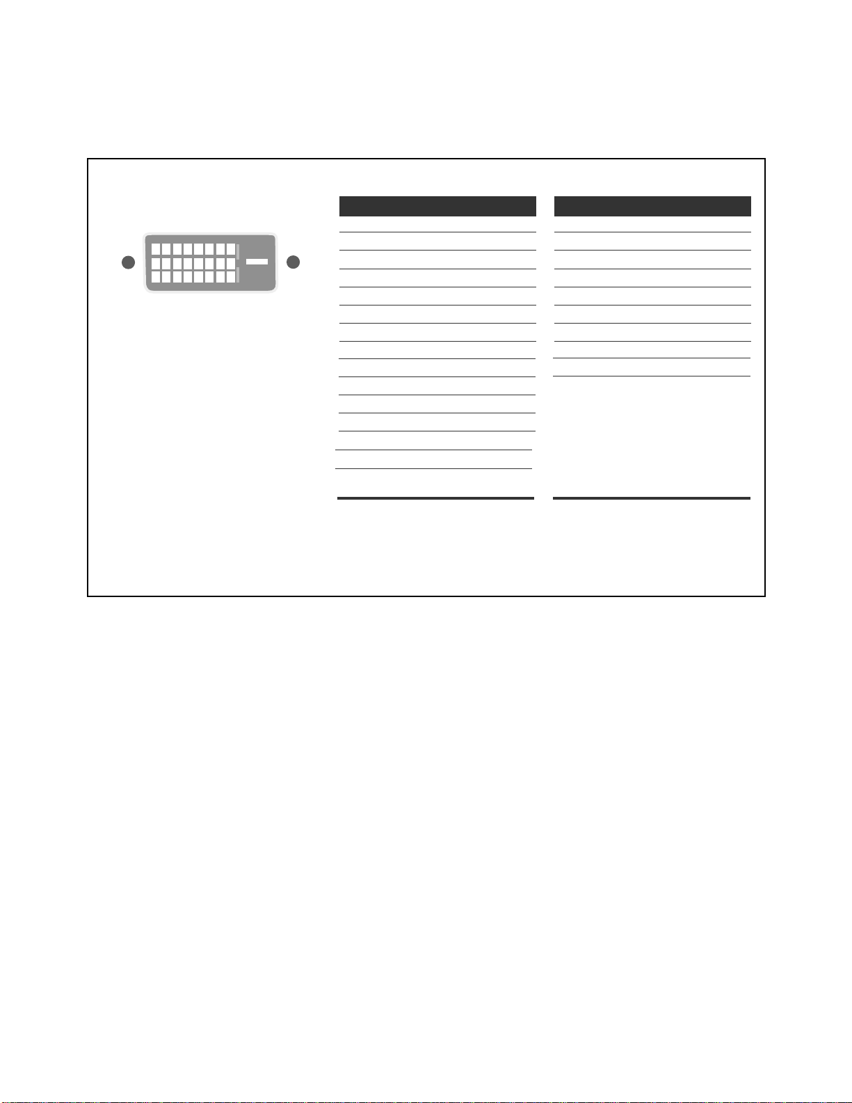
Signal Connector Pin Assignment
Pin Signal (DVI-D)
1
2
3
4
5
6
7
8
9
10
11
12
13
14
15
T. M. D. S. Data2T. M. D. S. Data2+
T. M. D. S. Data2/4 Shield
T. M. D. S. Data4T. M. D. S. Data4+
DDC Clock
DDC Data
Analog Vertical Sync.
T. M. D. S. Data1T. M. D. S. Data1+
T. M. D. S. Data1/3 Shield
T. M. D. S. Data3T. M. D. S. Data3+
+5V Power
Ground
(return for +5V,
H. Sync. and V. Sync.)
Pin Signal (DVI-D)
1
8
9
17
24
16
16
17
18
19
20
21
22
23
24
Hot Plug Detect
T. M. D. S. Data0T. M. D. S. Data0+
T. M. D. S. Data0/5 Shield
T. M. D. S. Data5T. M. D. S. Data5+
T. M. D. S. Clock Shield
T. M. D. S. Clock+
T. M. D. S. Clock-
T. M. D. S. (Transition Minimized Differential Signaling)
• DVI-D Connector (Digital)
Page 6

- 4 -
WARNING FOR THE SAFETY-RELATED COMPONENT.
• There are some special components used in LCD
monitor that are important for safety. These parts are
marked on the schematic diagram and the
replacement parts list. It is essential that these critical
parts should be replaced with the manufacturer’s
specified parts to prevent electric shock, fire or other
hazard.
• Do not modify original design without obtaining written
permission from manufacturer or you will void the
original parts and labor guarantee.
TAKE CARE DURING HANDLING THE LCD MODULE
WITH BACKLIGHT UNIT.
• Must mount the module using mounting holes arranged
in four corners.
• Do not press on the panel, edge of the frame strongly
or electric shock as this will result in damage to the
screen.
• Do not scratch or press on the panel with any sharp
objects, such as pencil or pen as this may result in
damage to the panel.
• Protect the module from the ESD as it may damage the
electronic circuit (C-MOS).
• Make certain that treatment person’s body are
grounded through wrist band.
• Do not leave the module in high temperature and in
areas of high humidity for a long time.
• The module not be exposed to the direct sunlight.
• Avoid contact with water as it may a short circuit within
the module.
• If the surface of panel become dirty, please wipe it off
with a softmaterial. (Cleaning with a dirty or rough cloth
may damage the panel.)
WARNING
BE CAREFUL ELECTRIC SHOCK !
• If you want to replace with the new backlight (CCFL) or
inverter circuit, must disconnect the AC adapter
because high voltage appears at inverter circuit about
650Vrms.
• Handle with care wires or connectors of the inverter
circuit. If the wires are pressed cause short and may
burn or take fire.
PRECAUTION
CAUTION
Please use only a plastic screwdriver to protect yourself
from shock hazard during service operation.
Page 7
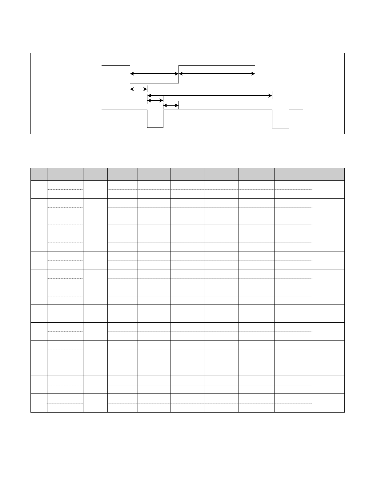
TIMING CHART
- 5 -
VIDEO
SYNC
B
D
C
F
E
A
<< Dot Clock (MHz), Horizontal Frequency (kHz), Vertical Frequency (Hz), Horizontal etc... (µs), Vertical etc... (ms) >>
H + 31.469 800 640 16 96 48
V – 70.8 449 350 37 2 60
H – 43.269 832 640 56 56 80
V – 85.0 509 480 1 3 25
H – 31.469 800 640 16 96 48
V – 59.94 525 480 10 2 33
H – 37.5 840 640 16 64 120
V – 75 500 480 1 3 16
H – 31.468 900 720 18 108 54
V + 70.8 449 400 12 2 35
H + 37.879 1056 800 40 128 88
V + 60.317 628 600 1 4 23
H + 46.875 1056 800 16 80 160
V + 75.0 625 600 1 3 21
H + 53.674 1048 800 32 64 152
V + 85.061 631 600 1 3 27
H+/– 49.725 1152 832 32 64 224
V+/– 74.55 667 624 1 3 39
H – 48.363 1344 1024 24 136 160
V – 60.0 806 768 3 6 29
H – 60.123 1312 1024 16 96 176
V – 75.029 800 768 1 3 28
H + 63.981 1688 1280 48 112 248
V + 60.02 1066 1024 1 3 38
H + 47.7 1680 1280 66 134 200
V + 60 795 768 1 3 23
Mode
H/V
Sort
1
2
3
4
5
6
7
8
9
10
11
12
13
25.175
28.321
25.175
31.5
36.0
40.0
49.5
56.25
57.283
65.0
78.75
108.0
80.14
640x350
70Hz
640x480
85Hz
640x480
60Hz
640x480
75Hz
720x400
70Hz
800x600
60Hz
800x600
75Hz
800x600
85Hz
832x624
75Hz
1024x768
60Hz
1024x768
75Hz
1280x1024
60Hz
1280x768
60Hz
Sync
Polarity
Frequency
Dot
Clock
Total Period
(E)
Video Active Time
(A)
Sync Duration
(D)
Back Porch
(F)
Front Porch
(C)
Resolution
Page 8
- 6 -
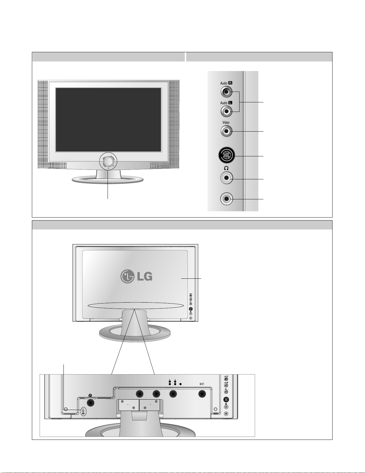
FRONT VIEW
REAR VIEW CONNECTOR PANEL
REAR VIEW
OPERATING INSTRUCTIONS
S-Video
MIC.In
Front Control Panel(P6)
DVI-I
Audio
RL
PbYPr
S-Video
Audio In
MIC.Out
MIC.In
Theft prevention
locking device
Back
Cap
AV(CVBS) Input
Terminal(Audio)
AV(CVBS) Input
Terminal(Video)
S-Video Input Terminal
Headphone/Earphone
Connection Terminal
Microphone Connection
Terminal
1
3
4
5
2
1.
DVI Digital Signal Connector (DVI-D or DVI-A)
2. TV Tuner Jack: Connect the antenna.
3. Connect the power cord.
4. Connent to the jack in the PC sound card
5. HDTV Input Terminal
DVI-I
DVI-I
Audio In
MIC.Out
MIC.Out
RL
RL
PbYPr
PbYPr
S-Video
S-Video
Audio
Audio
Audio In
MIC.In
MIC.In
Page 9
- 7 -
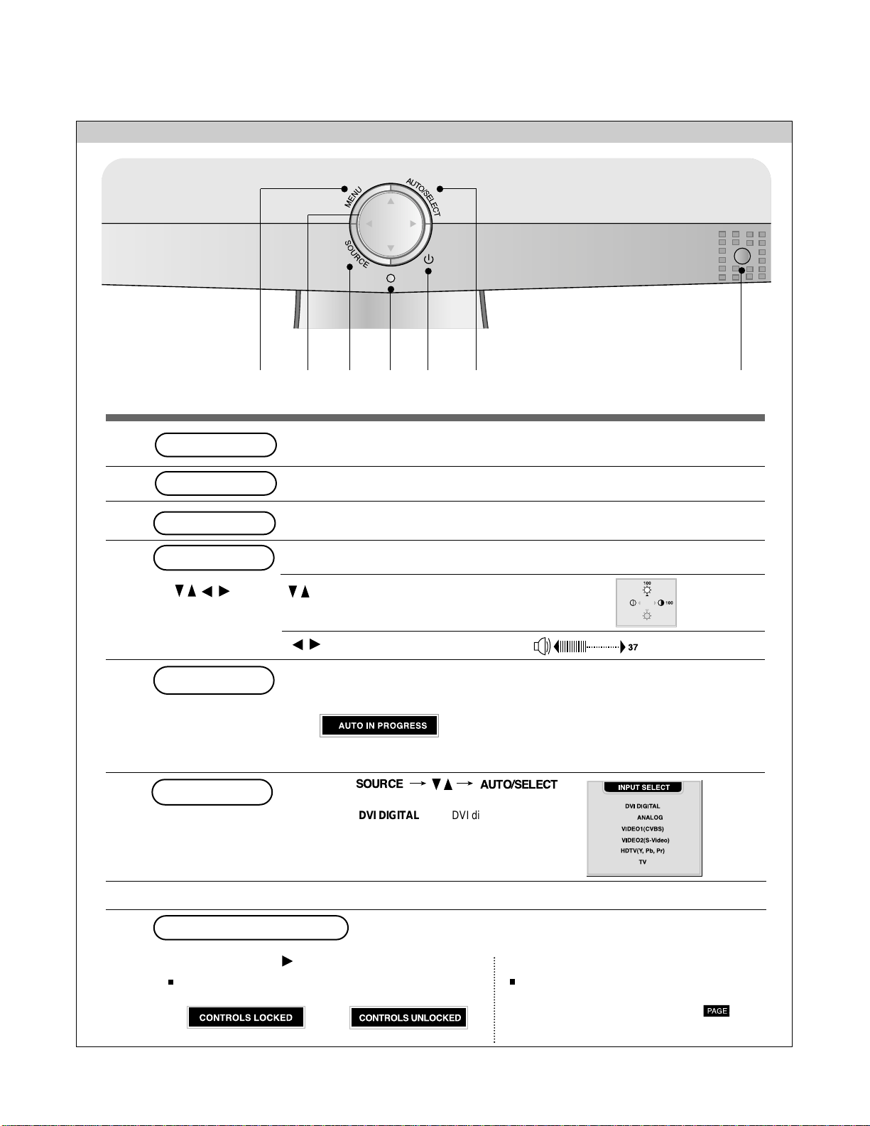
OPERATING INSTRUCTIONS
Front Control Panel
721643 5
• This Indicator lights up green when the display operates normally. If the display is in DPM
(Energy Saving) mode, this indicator color changes to amber.
• Press the button to turn on the power. Press the button again to turn it off.
Power LED
Power Button
• Adjust the volume.
• Use this button to directly control brightness and
contrast of the PC signal (DVI-D/DVI-A).
• Use this button to control the channel for the TV signal.
• Use this button to show/hide the OSD (On Screen Display) menu screen.
MENU Button
• Use the button to select an icon or adjust the setting in the OSD screen.
OSD Select/Adjust Button
[For DVI-ANALOG signal]
•Select the icon to adjust on the OSD screen.
•If you press the [AUTO/SELECT] button, automatic screen adjustment will be started.
[Other signals that DVI-ANALOG]
•The current signal and mode information will be displayed.
AUTO/SELECT Button
OSD Lock/Unlock Button
1
2
3
4
5
6
7
• Select the input signal
SOURCE
Button
• The unit that receives the signal from the remote controller.
DVI
AUTO/SELECT
SOURCE
DVI DIGITAL DVI digital signal
DVI ANALOG DVI analog signal
VIDEO1(CVBS) Composite video
VIDEO2(S-Video) S-Video
HDTV(Y, Pb, Pr) HD television
TV Television
•
OSD is locked
•
OSD is unlocked.
Use this button to lock/unlock OSD screen adjustment.
(Activated when pressed together longer than 5 seconds.)
Menu button +
Under the CAPTION & VCHIP menu, it is also
possible to lock/unlock the OSD screen
adjustment with the 'KEY LOCK' tab.
Page 10
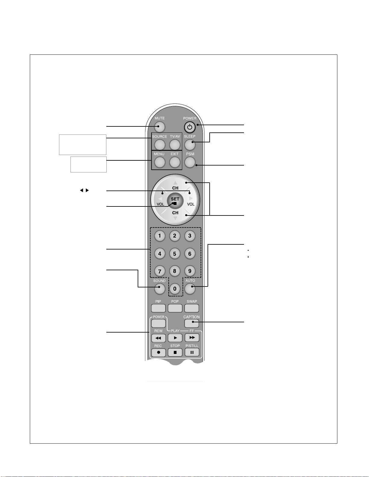
Remote Controller Buttons
- 8 -
Power On/Off Button
Channel Up/Down Button
•
Input Select Button
•
TV/AV Button
(See next page)
Sleep Button
When watching AV/HDTV/TV
-
The monitor will be automatically turned
off after a certain period of time.
Press this button repetitively to select an
appropriate time duration
PSM Button
When watching AV/HDTV/TV
- Automatically adjusts the image.
Press this button repetitively to set
the intended screen.
CAPTION Button
•
Menu Button
•
Exit Button
Auto Channel Button
TV: Automatic TV channel setup
PC: Automatic adjustment function
(Operational for the analog signal only)
Channel Number Select
Button
Operational at the TV mode only
Check Button
Sound Mode Select
Select the sound mode
: MONO/STEREO/SAP
Video Operation Button
Applicable for LG products only
Volume Button
Mute button
Page 11
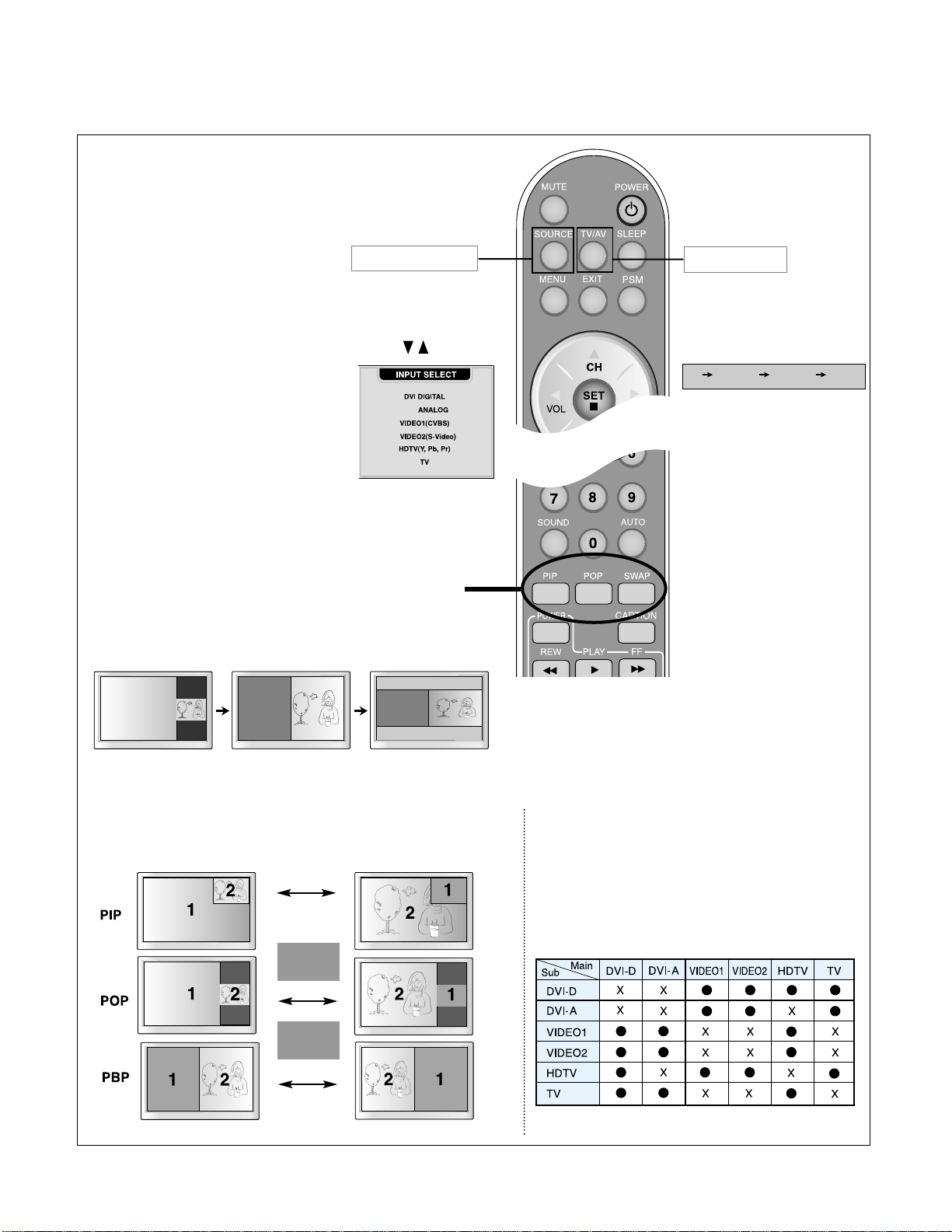
- 9 -
1. PIP (Picture in Picture) Button
The sub-screen moves to the next mode whenever you press this button.
: Small -> Large -> Off
2. POP (Picture out Picture) Button
The sub-screen moves to the next mode whenever you press this button.
: POP ON -> PBP(FULL) -> PBP(4:3) -> OFF
If you press the button once,
the following Input Signal
Window will appear. Select
the signal type you want
using the button.
This button will be enabled only
when you selected the TV/AV
signal. The signal type will be
changed with the following order.
Set the signal type you want.
POP ON PBP (FULL) PBP (4:3)
•
Input Select Button
•
TV/AV Button
TV VIDEO1 VIDEO2 HDTV
DVI
SWAP
SWAP
3. Swap Button
You can swap the main screen and the sub-screen when the PIP/POP/PBP
function is used..
When 'Input Signal 1' comes on in the main screen, only
'Input Signal 2' can be displayed on the sub-screen. On the
contrary, if the main screen displays 'Input Signal 2', the subscreen can display 'Input Signal 1' only. You can swap 'Input
Signal 1' and 'Input Signal 2' using the SWAP button.
<Table of PIP/POP/PBP Function Support>
Page 12
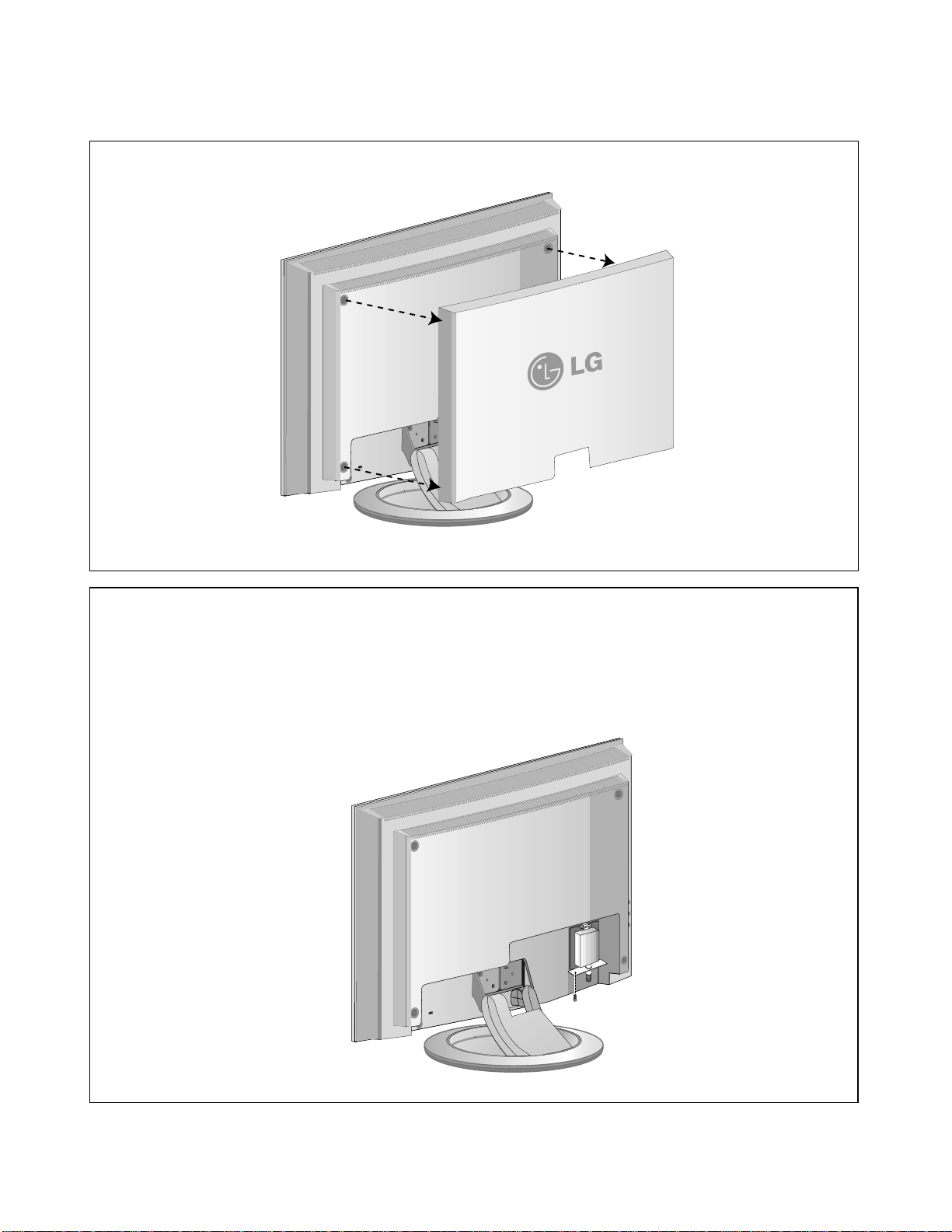
DISASSEMBLY
- 10 -
1.BACK CAP REMOVAL
1)Remove the Back cap.
2. TV TUNER REMOVAL
1)Remove the screw(a).
2)Remove the Tuner.
CAUTION
To prevent scratches on the back cover, make sure to
detach the tuner before detaching the back cover.
(a)
Page 13
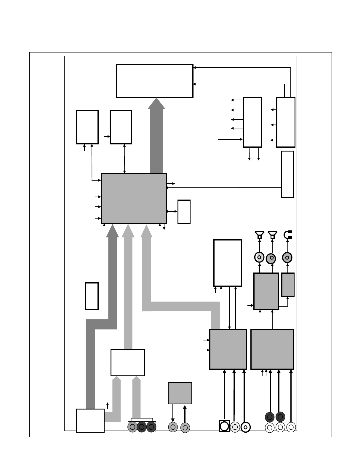
- 11 -
BLOCK DIAGRAM
DDR
128Mb
SDRAM
3.3V
(HY5DU283222Q4)
4Mb Flash
(29LV040B)
Memory
LCD
Module
Even
R,G,B
12V Inverter
12V
1.8V
2.5V
3.3V
5V
DC/DC
5V 12V
Converter
Tuner
33V
Lips
2.5V
3.3V
2.5V
Format Converter Circuit
1.8V
EEPROM
Data
(FSD 0 ..31)
DDC-D
PCB_PWR
INV_PWR
LCM_PWR
AMP_PWR
Data
(OCMD 0 ..7)
(FSA 0 ..11)
(OCMA 0 ..19)
PCB_PWR
INV_PWR
LCM_PWR
AMP_PWR
Control Signals
8V
12V
ADC_IN1/
ADC_IN2
Key Control
(gm1501)
Processor
Video Signal
TXD
RXD
H/ V Sync
Video Signal
Digital Signal
System
EEPROM
SP (L)
(M37136)
SP (R)
Caption/V-Chip
Amp
3.3V
2.5V
FB/R1/G1/B1
HS/VS/VOUT
Audio
12V
TPA6110
(TPA3004)
VAROUTR/L
DVI-I
In
MiC
5V
3.3V
Video
Decoder
Y/C
CVBS-in
(VPC3230)
Tuner CVBS
Audio
Decoder
5V
8V
DTV Audio
(MSP3420G)
PC Audio
CVBS Audio
Analog Signal
Switch
Analog
(BA7657F)
Out
AV
Board
H/ V Sync
RGB
YPbPr
HDTV
MiC
Page 14

- 12 -
DESCRIPTION OF BLOCK DIAGRAM
1. Input Signal Part
It is composed of four parts.
-PC signal input part:24pin DVI-I and PC Audio input
jack.
-AV Video input part: RCA Jack (CVBS signal), S-Video
Jack
-HDTV input part : YPbPr Jack and RL Stereo Audio
input jack
-TV signal input part: TV Tuner input Connector (TV
signal)
2. Video Signal Processor
It is composed of GM1501(U402)
GM1501 includes A/D Converter and LVDS Transmitter
GM1501 is directly Inputted Analog and Digital Signal
or Video Signal from Video Decoder
This Signal is converted into compatible Signal by
MICOM's control and then GM1501 transmit it to LCD
Module.
3. Analog Switch
It is composed of BA7657F
BA7657F Switch DVI-A to HDTV
4. Micom Controller
It is composed of 29LV040B(U403) its functions is
controlling each IC, display mode and frequency
through EEPROM and IIC communication.
5. Video decoder.
This block is composed of VPC3230D (U203) and
peripheral devices.
This IC analyzes input signal of CVBS, Y/C and output
analyzed signal (8bit interlace signal) to Video Signal
Processor block.
Analyzed signal has video control signals like Contrast,
Brightness, Sharpness, Color, tint signals Including
Adaptive Comb Filter.
6. Audio decoder part.
This block is composed of MSP3420G (U503) and
peripheral devices.
This IC analyzes Audio input signal through A/V Jack
and PC audio.
And output the analyzed signals to Audio Amplifier
(TPA3004).
7. Audio Amplifier
This block is composed of TPA3004 (U505) and
peripheral devices.
It amplifies audio signal input from Audio Decoder and
output amplified audio signal to Speaker, Audio Output
Jack.
8. Control
It receives outer key input, transmits the input to
Micom(U403).
There is key input part and remote controller receiver.
9. LIPS Part
It is composed of two parts
- Power Part functions that Input power converts to
33V,12V,5V power for operating circuits.
- Inverter Part functions that Input Power converts to
compatible "Vrms" value for operate LCD lamp.
Page 15

Windows EDID V1.0 User Manual
Operating System: MS Windows 98, 2000, XP
Port Setup: Windows 98 => Don’t need setup
Windows 2000, XP => Need to Port Setup.
This program is available to LCD Monitor only.
[Analog EDID]
At first select "DVI-Analog" in "Source" menu.
[Digital EDID]
At first select "DVI-Digital" in "Source" menu.
1. Port Setup
a) Copy “UserPort.sys” file to
“c:\WINNT\system32\drivers” folder
b) Run Userport.exe
c) Remove all default number
d) Add 300-3FF
e) Click Start button.
f) Click Exit button.
2. EDID Read & Write
1) Run WinEDID.exe
2) Edit Week of Manufacture, Year of Manufacture,
Serial Number
a) Input User Info Data
b) Click “Update” button
c) Click “ Write” button
- 13 -
ADJUSTMENT
Page 16

- 14 -
SERVICE OSD
1. Press the MENU key and then enter 3-0-2-0 with the
Direct Channel Select button on the remote control
(See the remote control figure on page 8) to access
the Service menu.
2. MODEL shows the factory model name of the
monitor. You don't need to make any adjustment in
this menu.
3. Select "OFF" in the NVRAM INITIAL using the
left/right key to return to the factory defaults.
4. Shows the monitor usage time. You don't need to
make any adjustment in this menu.
5. Shows the Micom version. You don't need to make
any adjustment in this menu.
6. Use this menu to test the Vchip. When you select
"OFF" using the left/right key, blocking will be
initiated depending on the rating signal.
SETUP
L172WALMODEL
NVRAM INITIAL
ELAPSED TIME 21 H
MICOM VERSION Ver. 49
VCHIP TEST
WB 0
UP / DOWN SELECT
OFF
OFF
SETUP
MODEL L172WAL
NVRAM INITIA OFFL
ELAPSED TIME 21 H
MICOM VERSION Ver. 49
VCHIP TEST
WB 0
OFF
SETUP
L172WALMODEL
NVRAM INITIAL
ELAPSED TIME 21 H
MICOM VERSION Ver. 49
VCHIP TEST
WB 0
UP / DOWN SELECT
OFF
OFF
SETUP
MODEL L172WAL
NVRAM INITIA OFFL
ELAPSED TIME 21 H
MICOM VERSION Ver. 49
VCHIP TEST
WB 0
OFF
UP / DOWN SELECT
SETUP
MODEL L172WAL
NVRAM INITIA OFFL
ELAPSED TIME 21 H
MICOM VERSION Ver. 49
VCHIP TEST
WB 0
UP / DOWN SELECT
OFF
UP / DOWN SELECT
SETUP
MODEL L172WAL
NVRAM INITIA OFFL
ELAPSED TIME 21 H
MICOM VERSION Ver. 49
VCHIP TEST
WB 0
UP / DOWN SELECT
OFF
Page 17

- 15 -
SETUP
7. Use this menu to adjust white balance.
Press the left/right key in the black screen to adjust
black. The WB value can be changed from 0 to 1.
8. Press the left/right key in the white screen to adjust
white. The WB value can be changed from 1 to 2.
220
IBM
Compatible PC
PARALLEL PORT
Power inlet (required)
Power LED
ST Switch
Power Select Switch
(110V/220V)
Control Line
Not used
RS232C
PARALLEL
V-SYNC
POWER
ST
VGS
MONITOR
E
E
V-Sync On/Off Switch
(Switch must be ON.)
F
F
A
A
B
B
C
C
15
10
5
5
69
1
1
1
14
13
25
6
5V
5V
5V
4.7K
4.7K
4.7K
74LS06
74LS06
OFF ON
OFF
ON
11
S-Video
DVI-I
Audio
RL
PbYPr
S-Video
Audio In
MIC.Out
MIC.In
Video Signal
Generator
Figure 1. Cable Connection
SETUP
MODEL L172WAL
NVRAM INITIA OFFL
ELAPSED TIME 21 H
MICOM VERSION Ver. 49
VCHIP TEST
OFF
WB 0
UP / DOWN SELECT
MODEL L172WAL
NVRAM INITIA OFFL
ELAPSED TIME 21 H
MICOM VERSION Ver. 49
VCHIP TEST
OFF
WB 1
UP / DOWN SELECT
Page 18

- 16 -
TROUBLESHOOTING GUIDE
1. NO POWER
NO POWER
(POWER INDICATOR OFF)
CHECK LIPS POWER
BOARD
CHECK J601
VOLTAGE
(33V, 12V, 5V)?
NO
CHECK KEY
CONTROL BOARD
YES
YES
YES
CHECK X401
CHECK
X401
(14.318MHz) ?
NO
CHECK MICOM(U402)
CHECK
DATA LINE of
U403 ?
NO
Page 19

- 17 -
2. NO RASTER(OSD IS NOT DISPLAYED)
NO RASTER
(OSD IS NOT DISPLAYED)
CHECK THE PERIPHERAL
IC U402
CHECK U402?
NO
CHECK THE PERIPHERAL
IC U402
CHECK
LVDS OUTPUT
(J401)?
NO
CHECK INVERTER
CABLE
YES
YES
YES
YES
CHECK BOTTOM OF LIPS
(Q201~Q204)
CHECK
LIPS POWER
NO
Page 20

- 18 -
3. NO RASTER ON VIDEO SIGNAL INPUT
NO RASTER ON VIDEO SIGNAL
CHECK CABLE OF VIDEO/COMPONENT
CHECK THE PERIPHERAL IC
OF VPC3230(U203)
CHECK THE PERIPHERAL IC
OF GM1501(U402)
CHECK VPC3230(U203) I/O SIGNAL
CHECK GM1501(U402)
NO
YES
YES
NO
YES
Page 21

- 19 -
4. NO RASTER ON TV SIGNAL INPUT
NO RASTER ON TV SIGNAL
CHECK CONNECTION OF TV
TUNER AND ANTENNA
SELECT AUTO CH OF OSD
CHECK THE PERIPHERAL IC
OF VPC3230(U203)
CHECK THE PERIPHERAL IC
OF GM1501(U402)
CHECK TV CH
CHECK VPC3230(U203) I/O
SIGNAL
CHECK GM1501(U402)
POWER CHECK OF TUNER(TU701) : L701(33V), L702(5V)
POWER CHECK OF VPC3230(U203) :L205(5V), L213(3.3V)
POWER CHECK OF GM1501(U402)
NO
NO
YES
YES
NO
Page 22

- 20 -
5. SOUND TROBLE SHOOTING
NO SOUND OUTPUT
CHECK SOUND OF VCR, HDTV,PC
(TV)CHECK CONNECTION OF TUNER
AND ANTENNA
INPUT: CHECK THE PERIPHERAL IC
OF MSP3420G(U503)
OUTPUT: CHECK THE PERIPHERAL IC
OF TPA3004(U505)
CHECK CONNECTION OF
SPEAKER ON MONITOR
CHECK SOUND INPUT
=>PC SOUND(J505)
=>VIDEO, HDTV SOUND
CHECK THE PERIPHERAL IC OF
MSP3420G(U503)
CHECK MSP3420G(U503) I/O SIGNAL
CHECK TPA3004(U505) I/O SIGNAL
CONNECTOR CHECK
POWER CHECK OF MSP3420G(U503) : L514(8V), L509(5V)
POWER CHECK OF TPA3004(U505) : C550(12V)
NO
YES
YES
YES
NO
NO
Page 23

- 21 -
6. NO RASTER STATE ON ANALOG SIGNAL
NO RASTER ON ANALOG SIGNAL
CONNECTOR(J102) CHECK
CHECK THE PERIPHERAL IC
OF GM1501(U402)
CHECK THE PERIPHERAL IC
OF GM1501(U402)
CHECK THE PERIPHERAL IC
OF DVI-A(J102)
CHECK I/O SYNC OF BA7657(U103)
CHECK ADC INPUT SIGNAL IN
GN1501(U402)
CHECK GM1501(U402) I/O SIGNAL
CHECK LVDS I/O SIGNAL
POWER CHECK OF BA7657(U103) : L102(5V)
POWER CHECK OF GM1501(U402)
POWER CHECK OF LVDS OUTPUT: J401
NO
NO
YES
YES
YES
YES
YES
NO
Page 24

- 22 -
7. NO RASTER STATE ON DIGITAL SIGNAL
NO RASTER STATE ON DIGITAL SIGNAL
CONNECTOR(J102) CHECK
CHECK THE PERIPHERAL IC
OF GM1501(U402)
CHECK GM1501(U402) I/O SIGNAL
CHECK LVDS I/O SIGNAL
POWER CHECK OF GM1501(U402)
POWER CHECK OF LVDS OUTPUT: J401
CHECK THE PERIPHERAL IC
OF GM1501(U402)
NO
NO
Page 25

- 23 -
WIRING DIAGRAM
J601
J201
J503
J402
J401
J501
Connector Ass’y P/N:
6631T20029A
Connector Ass’y P/N:
6631T20029E
Connector Ass’y P/N:
6631T20010C
Connector Ass’y P/N:
6631T20010B
Connector Ass’y P/N:
6631T11016C
Connector Ass’y P/N:
6631T20029F
Page 26

- 24 -
EXPLODED VIEW
Page 27

- 25 -
EXPLODED VIEW PARTS LIST
Ref. No.
1
2
3
4
5
6
7
8
9
10
11
12
13
14
15
16
17
18
19
20
21
22
23
24
25
26
27
28
29
30
Part No.
3091TKL093B
6304FLP061B
3809TKL064B
3043TKK143A
3550TKK427B
6401TZZ038A
6871TST461A
6871TVT365A
4814TKK257A
6631T11016C
4951TKS140A
6871TPT262B
3313TL7025B
6871TMT493B
6700NF0004B
4950TKK595A
4951TKK164A
4951TKK163A
4950TKK678A
4810TKK220A
3550TKK430A
6852TAZ006B
6852TAZ006D
6852TAZ006K
6852TAZ006N
6866TDV001E
6866TDV004C
6410TUW002B
4930TKK048A
6710T00003G
Description
CABINET ASSEMBLY, L172WAL BRAND L084 US PC+ABS
LCD(LIQUID CRYSTAL DISPLAY), LC171W03-A4K3 LG PHILPS TFT COLOR 17.1" WIDE
BACK COVER ASSEMBLY, L172WAL L067 US PC+ABS
TILT SWIVEL ASSEMBLY, L172WA K428 BRAND
COVER, L172WAL BACK DECORATION PC/ABS
SPEAKER ASSEMBLY, L172WAL K103B081,3W,8OHM,5PIN
PWB(PCB) ASSEMBLY, SUB, L172WAL CONTROL TOTAL BRAND CL-56
PWB(PCB) ASSEMBLY, VIDEO, L172WAL VIDEO TOTAL BRAND CL-56
SHIELD, SIDE AV-PCB L172WA
CONNECTOR ASSEMBLY, 20P H-H 100MM UL20276 I/FACE CABLE LB500K
METAL ASSEMBLY, FRAME MAIN L172WA
PWB(PCB) ASSEMBLY, POWER, L172WAL POWER TOTAL SUNGHO BRAND 17" WIDE FOR LPL
MAIN TOTAL ASSEMBLY, L172WAL BRAND CL-56
PWB(PCB) ASSEMBLY, MAIN, L172WAL ALUST BRAND CL-56 TOTAL
TUNER, TAFH-HOOIP LG INOTEK NTSC FS TUNNER FOR L3020AL
METAL, PLATE TV TUNER
METAL ASSEMBLY, FIX MAIN PCB L172WA
METAL ASSEMBLY, REAR L172WA
METAL, PLATE BACK L172WA
BRACKET, L1801FP EMI INSERT
COVER, L172WA BACK STAND
CORD, A/V, RCA CABLE UL2863 AWG28 3000MM BLACK(9930) DH-3P-N300C LM295B
CORD, A/V, DIN CABLE UL 2990-9C(5.5) 1560MM BLACK(9930) DH-150DIN LM295B
CORD, A/V, A/V KHC-ST-3-0001 UL 2851 #28-2C 1560MM GRAY(85964) KSD PINK-PINK
CORD, A/V, A/V KCA-ST-3-0011 UL2851 AWG28 1560MM GRAY(85964) LIME-L/BLUE WITH CORE L2320AL
CABLE, DVI, UL2990 DT 2000MM BLACK(9930) L172WAL DM
CABLE, DVI, UL20276 DT 2000MM GRAY(85964) LB885C DM
POWER CORD, SP305+IS14 I-SHENG UL/CSA 1870MM WALL 85964 GRAY
HOLDER, CABLE L16.5*H10
REMOTE CONTROLLER, L3020AL ALUST NTSC 30" AV/TV
Page 28

- 26 -
DATE: 2003. 12. 15.
*S *AL LOC. NO. PART NO. DESCRIPTION / SPECIFICATION
C101 0CK104CK56A 0.1UF 1608 50V 10% R/TP X7R
C103 0CH3104K566 0.1UF 50V 10% X7R 2012 R/TP
C104 0CK224CF56A 0.22UF 1608 16V 10% R/TP X7R
C105 0CK224CF56A 0.22UF 1608 16V 10% R/TP X7R
C106 0CK224CF56A 0.22UF 1608 16V 10% R/TP X7R
C107 0CC331CK41A 330PF 1608 50V 5% R/TP NP0
C108 0CK224CF56A 0.22UF 1608 16V 10% R/TP X7R
C109 0CK224CF56A 0.22UF 1608 16V 10% R/TP X7R
C110 0CK224CF56A 0.22UF 1608 16V 10% R/TP X7R
C111 0CK224CF56A 0.22UF 1608 16V 10% R/TP X7R
C112 0CC331CK41A 330PF 1608 50V 5% R/TP NP0
C113 0CC331CK41A 330PF 1608 50V 5% R/TP NP0
C114 0CK224CF56A 0.22UF 1608 16V 10% R/TP X7R
C115 0CK103CK51A 0.01UF 1608 50V 10% R/TP B(Y5
C116 0CH6101K416 100PF 50V J NP0 2012 R/TP
C118 0CK103CK51A 0.01UF 1608 50V 10% R/TP B(Y5
C119 0CH3104K566 0.1UF 50V 10% X7R 2012 R/TP
C120 0CH6101K416 100PF 50V J NP0 2012 R/TP
C121 0CK104CK56A 0.1UF 1608 50V 10% R/TP X7R
C122 0CK104CK56A 0.1UF 1608 50V 10% R/TP X7R
C123 0CK104CK56A 0.1UF 1608 50V 10% R/TP X7R
C124 0CK104CK56A 0.1UF 1608 50V 10% R/TP X7R
C125 0CC101CK41A 100PF 1608 50V 5% R/TP NP0
C126 0CH3104K566 0.1UF 50V 10% X7R 2012 R/TP
C127 0CH3104K566 0.1UF 50V 10% X7R 2012 R/TP
C128 0CK224CF56A 0.22UF 1608 16V 10% R/TP X7R
C129 0CK224CF56A 0.22UF 1608 16V 10% R/TP X7R
C130 0CK224CF56A 0.22UF 1608 16V 10% R/TP X7R
C131 0CK224CF56A 0.22UF 1608 16V 10% R/TP X7R
C132 0CK103CK51A 0.01UF 1608 50V 10% R/TP B(Y5
C134 0CK103CK51A 0.01UF 1608 50V 10% R/TP B(Y5
C139 0CK103CK51A 0.01UF 1608 50V 10% R/TP B(Y5
C142 0CH8476F691 47UF 16V 20% 105STD (CYL) R/T
C143 0CH8476F691 47UF 16V 20% 105STD (CYL) R/T
C144 0CH8476F691 47UF 16V 20% 105STD (CYL) R/T
C145 0CH8476F691 47UF 16V 20% 105STD (CYL) R/T
C146 0CH8476F691 47UF 16V 20% 105STD (CYL) R/T
C153 0CH8476F691 47UF 16V 20% 105STD (CYL) R/T
C154 0CH8476F691 47UF 16V 20% 105STD (CYL) R/T
C157 0CH3103K516 10000PF 50V 10% B(Y5P) 2012 R
C158 0CH3103K516 10000PF 50V 10% B(Y5P) 2012 R
C159 0CH3103K516 10000PF 50V 10% B(Y5P) 2012 R
C160 0CH3103K516 10000PF 50V 10% B(Y5P) 2012 R
C161 0CH3103K516 10000PF 50V 10% B(Y5P) 2012 R
C162 0CH3103K516 10000PF 50V 10% B(Y5P) 2012 R
C163 0CK474CH94A 0.47UF 1608 25V 80%,-20% R/TP
C164 0CH6471K416 470F 50V J NP0 2012 R/TP
C179 0CE477EF610 470UF KMG,RD 16V 20% BULK FL
C180 0CE106CK610 10UF SHL,SD 50V 20% BULK FL
C184 0CK104CK56A 0.1UF 1608 50V 10% R/TP X7R
C201 0CC120CK41A 12PF 1608 50V 5% R/TP NP0
C202 0CC331CK41A 330PF 1608 50V 5% R/TP NP0
DATE: 2003. 12. 15.
*S *AL LOC. NO. PART NO. DESCRIPTION / SPECIFICATION
C203 0CK474CH94A 0.47UF 1608 25V 80%,-20% R/TP
C204 0CC120CK41A 12PF 1608 50V 5% R/TP NP0
C205 0CH3104K566 0.1UF 50V 10% X7R 2012 R/TP
C206 0CK105CF94A 1UF 1608 16V 80%,-20% R/TP F(
C207 0CK473CK56A 47000PF 1608 50V 10% R/TP X7R
C208 0CC331CK41A 330PF 1608 50V 5% R/TP NP0
C209 0CK474CH94A 0.47UF 1608 25V 80%,-20% R/TP
C210 0CK473CK56A 47000PF 1608 50V 10% R/TP X7R
C211 0CC331CK41A 330PF 1608 50V 5% R/TP NP0
C212 0CC180CK41A 18PF 1608 50V 5% R/TP NP0
C213 0CH8106F691 10UF 16V 20% 105STD (CYL) R/T
C214 0CC180CK41A 18PF 1608 50V 5% R/TP NP0
C215 0CK104CK56A 0.1UF 1608 50V 10% R/TP X7R
C216 0CH3104K566 0.1UF 50V 10% X7R 2012 R/TP
C217 0CK104CK56A 0.1UF 1608 50V 10% R/TP X7R
C218 0CH3104K566 0.1UF 50V 10% X7R 2012 R/TP
C219 0CK152CK51A 1500PF 1608 50V 10% R/TP B(Y5
C220 0CH8106F691 10UF 16V 20% 105STD (CYL) R/T
C221 0CH3104K566 0.1UF 50V 10% X7R 2012 R/TP
C222 0CK472CK51A 4700PF 1608 50V 10% R/TP B(Y5
C223 0CC391CK41A 390PF 1608 50V 5% NP0 R/TP
C224 0CK104CK56A 0.1UF 1608 50V 10% R/TP X7R
C225 0CK104CK56A 0.1UF 1608 50V 10% R/TP X7R
C226 0CK152CK51A 1500PF 1608 50V 10% R/TP B(Y5
C227 0CK103CK51A 0.01UF 1608 50V 10% R/TP B(Y5
C228 0CK224CF56A 0.22UF 1608 16V 10% R/TP X7R
C229 0CC331CK41A 330PF 1608 50V 5% R/TP NP0
C231 0CH6152K406 1500PF 50V J SL 2012 R/TP
C232 0CK474CH94A 0.47UF 1608 25V 80%,-20% R/TP
C233 0CH3472K516 4700PF 50V K B 2012 R/TP
C234 0CH8106F691 10UF 16V 20% 105STD (CYL) R/T
C235 0CH3104K566 0.1UF 50V 10% X7R 2012 R/TP
C236 0CH3104K566 0.1UF 50V 10% X7R 2012 R/TP
C237 0CH3104K566 0.1UF 50V 10% X7R 2012 R/TP
C238 0CH8476F691 47UF 16V 20% 105STD (CYL) R/T
C239 0CK103CK51A 0.01UF 1608 50V 10% R/TP B(Y5
C240 0CC100CK41A 10PF 1608 50V 5% R/TP NP0
C242 0CK474CH94A 0.47UF 1608 25V 80%,-20% R/TP
C243 0CC331CK41A 330PF 1608 50V 5% R/TP NP0
C245 0CK474CH94A 0.47UF 1608 25V 80%,-20% R/TP
C246 0CC681CK41A 680PF 1608 50V 5% NP0 R/TP
C247 0CC391CK41A 390PF 1608 50V 5% NP0 R/TP
C248 0CK152CK51A 1500PF 1608 50V 10% R/TP B(Y5
C249 0CK224CF56A 0.22UF 1608 16V 10% R/TP X7R
C251 0CK474CH94A 0.47UF 1608 25V 80%,-20% R/TP
C252 0CH3104K566 0.1UF 50V 10% X7R 2012 R/TP
C253 0CC100CK41A 10PF 1608 50V 5% R/TP NP0
C254 0CK472CK51A 4700PF 1608 50V 10% R/TP B(Y5
C255 0CC391CK41A 390PF 1608 50V 5% NP0 R/TP
C256 0CC101CK41A 100PF 1608 50V 5% R/TP NP0
C257 0CC101CK41A 100PF 1608 50V 5% R/TP NP0
C259 0CK104CK56A 0.1UF 1608 50V 10% R/TP X7R
C260 0CC101CK41A 100PF 1608 50V 5% R/TP NP0
C261 0CK104CK56A 0.1UF 1608 50V 10% R/TP X7R
REPLACEMENT PARTS LIST
CAUTION: BEFORE REPLACING ANY OF THESE COMPONENTS,
READ CAREFULLY THE SAFETY PRECAUTIONS IN THIS MANUAL.
* NOTE : S SAFETY Mark
AL ALTERNATIVE PARTS
MAIN BOARD
CAPACITORS
Page 29

DATE: 2003. 12. 15.
*S *AL LOC. NO. PART NO. DESCRIPTION / SPECIFICATION
C262 0CK105CF94A 1UF 1608 16V 80%,-20% R/TP F(
C266 0CK472CK51A 4700PF 1608 50V 10% R/TP B(Y5
C267 0CK105CF94A 1UF 1608 16V 80%,-20% R/TP F(
C268 0CK104CK56A 0.1UF 1608 50V 10% R/TP X7R
C269 0CK152CK51A 1500PF 1608 50V 10% R/TP B(Y5
C270 0CK224CF56A 0.22UF 1608 16V 10% R/TP X7R
C271 0CH8226F691 22UF 16V 20% 105STD (CYL) R/T
C272 0CH8476F691 47UF 16V 20% 105STD (CYL) R/T
C273 0CK474CH94A 0.47UF 1608 25V 80%,-20% R/TP
C274 0CK473CK56A 47000PF 1608 50V 10% R/TP X7R
C275 0CC331CK41A 330PF 1608 50V 5% R/TP NP0
C276 0CH6201K416 200PF 50V J NP0 2012 R/TP
C277 0CH6201K416 200PF 50V J NP0 2012 R/TP
C278 0CC561CK41A 560PF 1608 50V 5% NP0 R/TP
C284 0CC101CK41A 100PF 1608 50V 5% R/TP NP0
C285 0CC101CK41A 100PF 1608 50V 5% R/TP NP0
C289 0CH6102K406 1000PF 50V J SL 2012 R/TP
C292 0CH3104K566 0.1UF 50V 10% X7R 2012 R/TP
C293 0CK104CK56A 0.1UF 1608 50V 10% R/TP X7R
C294 0CK104CK56A 0.1UF 1608 50V 10% R/TP X7R
C295 0CK104CK56A 0.1UF 1608 50V 10% R/TP X7R
C296 0CK104CK56A 0.1UF 1608 50V 10% R/TP X7R
C369 0CH3104K566 0.1UF 50V 10% X7R 2012 R/TP
C370 0CH3104K566 0.1UF 50V 10% X7R 2012 R/TP
C401 0CH3104K566 0.1UF 50V 10% X7R 2012 R/TP
C402 0CK104CK56A 0.1UF 1608 50V 10% R/TP X7R
C403 0CC102CK41A 1000PF 1608 50V 5% R/TP NP0
C404 0CC102CK41A 1000PF 1608 50V 5% R/TP NP0
C405 0CC102CK41A 1000PF 1608 50V 5% R/TP NP0
C406 0CK104CK56A 0.1UF 1608 50V 10% R/TP X7R
C407 0CH8226F691 22UF 16V 20% 105STD (CYL) R/T
C408 0CH3104K566 0.1UF 50V 10% X7R 2012 R/TP
C409 0CK104CK56A 0.1UF 1608 50V 10% R/TP X7R
C412 0CK104CK56A 0.1UF 1608 50V 10% R/TP X7R
C413 0CK104CK56A 0.1UF 1608 50V 10% R/TP X7R
C414 0CK104CK56A 0.1UF 1608 50V 10% R/TP X7R
C415 0CK104CK56A 0.1UF 1608 50V 10% R/TP X7R
C416 0CK104CK56A 0.1UF 1608 50V 10% R/TP X7R
C417 0CK104CK56A 0.1UF 1608 50V 10% R/TP X7R
C418 0CK104CK56A 0.1UF 1608 50V 10% R/TP X7R
C420 0CK104CK56A 0.1UF 1608 50V 10% R/TP X7R
C424 0CC220CK41A 22PF 1608 50V 5% R/TP NP0
C425 0CH3104K566 0.1UF 50V 10% X7R 2012 R/TP
C426 0CK104CK56A 0.1UF 1608 50V 10% R/TP X7R
C427 0CK104CK56A 0.1UF 1608 50V 10% R/TP X7R
C429 0CC150CK41A 15PF 1608 50V 5% R/TP NP0
C430 0CH8475J611 4.7UF 35V M 85STD(CYL) R/TP
C435 0CH3104K566 0.1UF 50V 10% X7R 2012 R/TP
C459 0CH3104K566 0.1UF 50V 10% X7R 2012 R/TP
C460 0CH3104K566 0.1UF 50V 10% X7R 2012 R/TP
C461 0CH3104K566 0.1UF 50V 10% X7R 2012 R/TP
C462 0CH3104K566 0.1UF 50V 10% X7R 2012 R/TP
C464 0CC220CK41A 22PF 1608 50V 5% R/TP NP0
C468 0CH3104K566 0.1UF 50V 10% X7R 2012 R/TP
C469 0CH3104K566 0.1UF 50V 10% X7R 2012 R/TP
C470 0CH3104K566 0.1UF 50V 10% X7R 2012 R/TP
C471 0CH3104K566 0.1UF 50V 10% X7R 2012 R/TP
C472 0CH3104K566 0.1UF 50V 10% X7R 2012 R/TP
C473 0CH3104K566 0.1UF 50V 10% X7R 2012 R/TP
C474 0CH3104K566 0.1UF 50V 10% X7R 2012 R/TP
C475 0CH3104K566 0.1UF 50V 10% X7R 2012 R/TP
C476 0CH3104K566 0.1UF 50V 10% X7R 2012 R/TP
DATE: 2003. 12. 15.
*S *AL LOC. NO. PART NO. DESCRIPTION / SPECIFICATION
C477 0CH3104K566 0.1UF 50V 10% X7R 2012 R/TP
C478 0CH3104K566 0.1UF 50V 10% X7R 2012 R/TP
C479 0CH3104K566 0.1UF 50V 10% X7R 2012 R/TP
C480 0CH3104K566 0.1UF 50V 10% X7R 2012 R/TP
C481 0CH3104K566 0.1UF 50V 10% X7R 2012 R/TP
C482 0CH3104K566 0.1UF 50V 10% X7R 2012 R/TP
C483 0CH3104K566 0.1UF 50V 10% X7R 2012 R/TP
C484 0CH3104K566 0.1UF 50V 10% X7R 2012 R/TP
C487 0CH3104K566 0.1UF 50V 10% X7R 2012 R/TP
C488 0CH3104K566 0.1UF 50V 10% X7R 2012 R/TP
C489 0CH3104K566 0.1UF 50V 10% X7R 2012 R/TP
C490 0CH3104K566 0.1UF 50V 10% X7R 2012 R/TP
C491 0CH3104K566 0.1UF 50V 10% X7R 2012 R/TP
C492 0CH3104K566 0.1UF 50V 10% X7R 2012 R/TP
C493 0CH3104K566 0.1UF 50V 10% X7R 2012 R/TP
C494 0CH3104K566 0.1UF 50V 10% X7R 2012 R/TP
C495 0CH3104K566 0.1UF 50V 10% X7R 2012 R/TP
C496 0CH3104K566 0.1UF 50V 10% X7R 2012 R/TP
C497 0CH3104K566 0.1UF 50V 10% X7R 2012 R/TP
C498 0CH3104K566 0.1UF 50V 10% X7R 2012 R/TP
C499 0CH3104K566 0.1UF 50V 10% X7R 2012 R/TP
C501 0CK224CF56A 0.22UF 1608 16V 10% R/TP X7R
C502 0CE475EK638 4.7UF KMG 50V 20% FM5 TP 5
C503 0CE227EF638 220UF KMG,RD 16V 20% TP 5 FM5
C504 0CE227EF638 220UF KMG,RD 16V 20% TP 5 FM5
C505 0CK474CH94A 0.47UF 1608 25V 80%,-20% R/TP
C506 0CK224CF56A 0.22UF 1608 16V 10% R/TP X7R
C507 0CK224CF56A 0.22UF 1608 16V 10% R/TP X7R
C508 0CC471CK41A 470PF 1608 50V 5% R/TP NP0
C509 0CK104CK56A 0.1UF 1608 50V 10% R/TP X7R
C510 0CC471CK41A 470PF 1608 50V 5% R/TP NP0
C512 0CK562CK51A 5600PF 1608 50V 10% R/TP B(Y5
C513 0CK105CF94A 1UF 1608 16V 80%,-20% R/TP F(
C514 0CK103CK51A 0.01UF 1608 50V 10% R/TP B(Y5
C515 0CK562CK51A 5600PF 1608 50V 10% R/TP B(Y5
C516 0CK562CK51A 5600PF 1608 50V 10% R/TP B(Y5
C517 0CK104CK56A 0.1UF 1608 50V 10% R/TP X7R
C518 0CK103CK51A 0.01UF 1608 50V 10% R/TP B(Y5
C519 0CK103CK51A 0.01UF 1608 50V 10% R/TP B(Y5
C520 0CK562CK51A 5600PF 1608 50V 10% R/TP B(Y5
C523 0CK104CK56A 0.1UF 1608 50V 10% R/TP X7R
C524 0CC221CK41A 220PF 1608 50V 5% R/TP NP0
C525 0CE226EK610 22UF KMG,RD 50V 20% FL BULK
C526 0CK105CF94A 1UF 1608 16V 80%,-20% R/TP F(
C527 0CK104CK56A 0.1UF 1608 50V 10% R/TP X7R
C528 0CH8476F691 47UF 16V 20% 105STD (CYL) R/T
C529 0CK104CK56A 0.1UF 1608 50V 10% R/TP X7R
C531 0CK104CK56A 0.1UF 1608 50V 10% R/TP X7R
C540 0CH8106F691 10UF 16V 20% 105STD (CYL) R/T
C541 0CK224CF56A 0.22UF 1608 16V 10% R/TP X7R
C542 0CK224CF56A 0.22UF 1608 16V 10% R/TP X7R
C548 0CK224CF56A 0.22UF 1608 16V 10% R/TP X7R
C549 0CK103CK51A 0.01UF 1608 50V 10% R/TP B(Y5
C550 0CE226EK610 22UF KMG,RD 50V 20% FL BULK
C551 0CH6471K416 470F 50V J NP0 2012 R/TP
C553 0CK104CK56A 0.1UF 1608 50V 10% R/TP X7R
C554 0CH6471K416 470F 50V J NP0 2012 R/TP
C556 0CC101CK41A 100PF 1608 50V 5% R/TP NP0
C557 0CC3R3CK01A 3.3PF 1608 50V 0.25 PF R/TP N
C558 0CC560CK41A 56PF 1608 50V 5% R/TP NP0
C559 0CC560CK41A 56PF 1608 50V 5% R/TP NP0
C560 0CC560CK41A 56PF 1608 50V 5% R/TP NP0
- 27 -
Page 30

DATE: 2003. 12. 15.
*S *AL LOC. NO. PART NO. DESCRIPTION / SPECIFICATION
C561 0CC3R3CK01A 3.3PF 1608 50V 0.25 PF R/TP N
C562 0CK104CK56A 0.1UF 1608 50V 10% R/TP X7R
C565 0CH8476F691 47UF 16V 20% 105STD (CYL) R/T
C566 0CK104CK56A 0.1UF 1608 50V 10% R/TP X7R
C569 0CK332CK51A 3300PF 1608 50V 10% R/TP B(Y5
C570 0CK332CK51A 3300PF 1608 50V 10% R/TP B(Y5
C572 0CH8476F691 47UF 16V 20% 105STD (CYL) R/T
C573 0CH8106F691 10UF 16V 20% 105STD (CYL) R/T
C574 0CH8106F691 10UF 16V 20% 105STD (CYL) R/T
C576 0CK104CK56A 0.1UF 1608 50V 10% R/TP X7R
C577 0CK103CK51A 0.01UF 1608 50V 10% R/TP B(Y5
C578 0CH3104K566 0.1UF 50V 10% X7R 2012 R/TP
C579 0CK105CF94A 1UF 1608 16V 80%,-20% R/TP F(
C580 0CK104CK56A 0.1UF 1608 50V 10% R/TP X7R
C581 0CK105CF94A 1UF 1608 16V 80%,-20% R/TP F(
C587 0CE226EK610 22UF KMG,RD 50V 20% FL BULK
C588 0CK104CK56A 0.1UF 1608 50V 10% R/TP X7R
C589 0CK104CK56A 0.1UF 1608 50V 10% R/TP X7R
C590 0CK105CF94A 1UF 1608 16V 80%,-20% R/TP F(
C591 0CK105CF94A 1UF 1608 16V 80%,-20% R/TP F(
C592 0CK105CF94A 1UF 1608 16V 80%,-20% R/TP F(
C593 0CK105CF94A 1UF 1608 16V 80%,-20% R/TP F(
C594 0CK105CF94A 1UF 1608 16V 80%,-20% R/TP F(
C598 0CC471CK41A 470PF 1608 50V 5% R/TP NP0
C599 0CC471CK41A 470PF 1608 50V 5% R/TP NP0
C601 0CE477EF610 470UF KMG,RD 16V 20% BULK FL
C602 0CH3103K516 10000PF 50V 10% B(Y5P) 2012 R
C603 0CK104CK56A 0.1UF 1608 50V 10% R/TP X7R
C604 0CH3103K516 10000PF 50V 10% B(Y5P) 2012 R
C605 0CK104CK56A 0.1UF 1608 50V 10% R/TP X7R
C606 0CE477EF610 470UF KMG,RD 16V 20% BULK FL
C607 0CE107WF6DC 100UF MVK 16V 20% R/TP(SMD) S
C608 0CK103CK51A 0.01UF 1608 50V 10% R/TP B(Y5
C609 0CK104CK56A 0.1UF 1608 50V 10% R/TP X7R
C610 0CK103CK51A 0.01UF 1608 50V 10% R/TP B(Y5
C611 0CK104CK56A 0.1UF 1608 50V 10% R/TP X7R
C612 0CK103CK51A 0.01UF 1608 50V 10% R/TP B(Y5
C613 0CK104CK56A 0.1UF 1608 50V 10% R/TP X7R
C614 0CE477EF610 470UF KMG,RD 16V 20% BULK FL
C615 0CE227EF638 220UF KMG,RD 16V 20% TP 5 FM5
C616 0CH3104K566 0.1UF 50V 10% X7R 2012 R/TP
C617 0CE477EF610 470UF KMG,RD 16V 20% BULK FL
C618 0CE477EF610 470UF KMG,RD 16V 20% BULK FL
C619 0CK104CK56A 0.1UF 1608 50V 10% R/TP X7R
C623 0CK104CK56A 0.1UF 1608 50V 10% R/TP X7R
C624 0CE227EF638 220UF KMG,RD 16V 20% TP 5 FM5
C625 0CK104CK56A 0.1UF 1608 50V 10% R/TP X7R
C630 0CK104CK56A 0.1UF 1608 50V 10% R/TP X7R
C631 0CK103CK51A 0.01UF 1608 50V 10% R/TP B(Y5
C632 0CH8226F691 22UF 16V 20% 105STD (CYL) R/T
C633 0CH8226F691 22UF 16V 20% 105STD (CYL) R/T
C635 0CE107WF6DC 100UF MVK 16V 20% R/TP(SMD) S
C637 0CH8226F691 22UF 16V 20% 105STD (CYL) R/T
C639 0CK103CK51A 0.01UF 1608 50V 10% R/TP B(Y5
C640 0CE107WF6DC 100UF MVK 16V 20% R/TP(SMD) S
C641 0CK104CK56A 0.1UF 1608 50V 10% R/TP X7R
C642 0CH8226F691 22UF 16V 20% 105STD (CYL) R/T
C644 0CK104CK56A 0.1UF 1608 50V 10% R/TP X7R
C645 0CE107WF6DC 100UF MVK 16V 20% R/TP(SMD) S
C648 0CH8226F691 22UF 16V 20% 105STD (CYL) R/T
C649 0CH8226F691 22UF 16V 20% 105STD (CYL) R/T
C652 0CE227EF638 220UF KMG,RD 16V 20% TP 5 FM5
DATE: 2003. 12. 15.
*S *AL LOC. NO. PART NO. DESCRIPTION / SPECIFICATION
C653 0CK104CK56A 0.1UF 1608 50V 10% R/TP X7R
C654 0CK104CK56A 0.1UF 1608 50V 10% R/TP X7R
C655 0CH8226F691 22UF 16V 20% 105STD (CYL) R/T
C657 0CK104CK56A 0.1UF 1608 50V 10% R/TP X7R
C670 0CH3104K566 0.1UF 50V 10% X7R 2012 R/TP
C672 0CK104CK56A 0.1UF 1608 50V 10% R/TP X7R
C673 0CH3104K566 0.1UF 50V 10% X7R 2012 R/TP
C690 0CK104CK56A 0.1UF 1608 50V 10% R/TP X7R
C691 0CE107WF6DC 100UF MVK 16V 20% R/TP(SMD) S
C694 0CK104CK56A 0.1UF 1608 50V 10% R/TP X7R
C701 0CH3104K566 0.1UF 50V 10% X7R 2012 R/TP
C702 0CH3104K566 0.1UF 50V 10% X7R 2012 R/TP
C703 0CH3104K566 0.1UF 50V 10% X7R 2012 R/TP
C705 0CH6100K116 10PF 50V D NP0 2012 R/TP
C706 0CH6100K116 10PF 50V D NP0 2012 R/TP
C707 0CH3104K566 0.1UF 50V 10% X7R 2012 R/TP
C708 0CH3105F946 1UF 16V Z F 2012 R/TP
C709 0CH3105F946 1UF 16V Z F 2012 R/TP
C710 0CH3105F946 1UF 16V Z F 2012 R/TP
C711 0CH3105F946 1UF 16V Z F 2012 R/TP
C712 0CH3104K566 0.1UF 50V 10% X7R 2012 R/TP
C714 0CE106CK610 10UF SHL,SD 50V 20% BULK FL
C715 0CH3104K566 0.1UF 50V 10% X7R 2012 R/TP
C716 0CE107EF610 100UF KMG,RD 16V 20% FL BULK
C717 0CH3104K566 0.1UF 50V 10% X7R 2012 R/TP
C718 0CH3104K566 0.1UF 50V 10% X7R 2012 R/TP
C719 0CH3104K566 0.1UF 50V 10% X7R 2012 R/TP
D101 0DS226009AA KDS226 TP KEC SOT-23 80V 300
D102 0DS226009AA KDS226 TP KEC SOT-23 80V 300
D110 0DS226009AA KDS226 TP KEC SOT-23 80V 300
D111 0DS226009AA KDS226 TP KEC SOT-23 80V 300
D112 0DS226009AA KDS226 TP KEC SOT-23 80V 300
D113 0DS226009AA KDS226 TP KEC SOT-23 80V 300
D114 0DS226009AA KDS226 TP KEC SOT-23 80V 300
D115 0DS226009AA KDS226 TP KEC SOT-23 80V 300
D121 0DS226009AA KDS226 TP KEC SOT-23 80V 300
D122 0DS226009AA KDS226 TP KEC SOT-23 80V 300
D123 0DS226009AA KDS226 TP KEC SOT-23 80V 300
D124 0DS226009AA KDS226 TP KEC SOT-23 80V 300
D125 0DS226009AA KDS226 TP KEC SOT-23 80V 300
D128 0DS226009AA KDS226 TP KEC SOT-23 80V 300
D501 0DS226009AA KDS226 TP KEC SOT-23 80V 300
D502 0DS226009AA KDS226 TP KEC SOT-23 80V 300
D503 0DS226009AA KDS226 TP KEC SOT-23 80V 300
D601 0DS226009AA KDS226 TP KEC SOT-23 80V 300
D701 0DS226009AA KDS226 TP KEC SOT-23 80V 300
D702 0DS226009AA KDS226 TP KEC SOT-23 80V 300
D703 0DS226009AA KDS226 TP KEC SOT-23 80V 300
ZD101 0DZ560009DA UDZ S 5.6B TP ROHM-K SOD323 2
ZD102 0DZ560009DA UDZ S 5.6B TP ROHM-K SOD323 2
ZD103 0DZ560009DA UDZ S 5.6B TP ROHM-K SOD323 2
ZD117 0DZ560009DA UDZ S 5.6B TP ROHM-K SOD323 2
ZD118 0DZ560009DA UDZ S 5.6B TP ROHM-K SOD323 2
ZD401 0DZ910009FE UDZS 9.1B TP ROHM - - 9.1V ZD501 0DZ560009DA UDZ S 5.6B TP ROHM-K SOD323 2
ZD502 0DZ560009DA UDZ S 5.6B TP ROHM-K SOD323 2
ZD505 0DZ560009DA UDZ S 5.6B TP ROHM-K SOD323 2
ZD506 0DZ560009DA UDZ S 5.6B TP ROHM-K SOD323 2
ZD507 0DZ560009DA UDZ S 5.6B TP ROHM-K SOD323 2
- 28 -
DIODEs
Page 31

DATE: 2003. 12. 15.
*S *AL LOC. NO. PART NO. DESCRIPTION / SPECIFICATION
ZD508 0DZ560009DA UDZ S 5.6B TP ROHM-K SOD323 2
ZD509 0DZ560009DA UDZ S 5.6B TP ROHM-K SOD323 2
ZD510 0DZ560009DA UDZ S 5.6B TP ROHM-K SOD323 2
ZD511 0DZ560009DA UDZ S 5.6B TP ROHM-K SOD323 2
ZD512 0DZ560009DA UDZ S 5.6B TP ROHM-K SOD323 2
ZD513 0DZ560009DA UDZ S 5.6B TP ROHM-K SOD323 2
ZD514 0DZ560009DA UDZ S 5.6B TP ROHM-K SOD323 2
ZD515 0DZ560009DA UDZ S 5.6B TP ROHM-K SOD323 2
ZD516 0DZ560009DA UDZ S 5.6B TP ROHM-K SOD323 2
ZD701 0DZ560009DA UDZ S 5.6B TP ROHM-K SOD323 2
ZD702 0DZ560009DA UDZ S 5.6B TP ROHM-K SOD323 2
ZD703 0DZ560009DA UDZ S 5.6B TP ROHM-K SOD323 2
ZD704 0DZ560009DA UDZ S 5.6B TP ROHM-K SOD323 2
ZD705 0DZ560009DA UDZ S 5.6B TP ROHM-K SOD323 2
U101 0ISS524202B S524A40X21(SCT0) SAMSUNG ELEC
U102 0ISS524202B S524A40X21(SCT0) SAMSUNG ELEC
U103 0IRH765700B BA7657F 24P,SOP TP INPUT SIG.
U104 0IMO140662A MC14066BDR2 14P,SOIC TP BILAT
U110 0DRCE00018A PACDN004 CAMD R/TP SOT143 5V
U111 0DRCE00018A PACDN004 CAMD R/TP SOT143 5V
U112 0DRCE00018A PACDN004 CAMD R/TP SOT143 5V
U113 0DRCE00018A PACDN004 CAMD R/TP SOT143 5V
U114 0DRCE00018A PACDN004 CAMD R/TP SOT143 5V
U115 0DRCE00018A PACDN004 CAMD R/TP SOT143 5V
U116 0DRCE00018A PACDN004 CAMD R/TP SOT143 5V
U117 0DRCE00018A PACDN004 CAMD R/TP SOT143 5V
U118 0DRCE00018A PACDN004 CAMD R/TP SOT143 5V
U119 0DRCE00018A PACDN004 CAMD R/TP SOT143 5V
U120 0DRCE00018A PACDN004 CAMD R/TP SOT143 5V
U121 0DRCE00018A PACDN004 CAMD R/TP SOT143 5V
U202 0IZZTSZ302A MITSUBISHI 52P SDIP ST V-CHIP
U203 0IIT323000E VPC3230D C5 80P QFP TRAY VIDE
U401 0IMMRHY051A HY5DU283222AQ-4 HYNIX 100P,LQ
U402 0IPRPGN011A GM1501 GENESIS 406P, TRAY UXG
U403 0IZZTSZ350B MACRONIX 32 PIN PLCC ST FLASH
U403 6620F00017A CCSD-32T-SM WOOYOUNG 32P PLCC
U404 0IMMRSS040C S524A60X51(SCT0) SAMSUNG ELEC
U407 0ISTLFA058A 74F14SCX FAIRCHILD 14P,SOIC R
U501 0IPRPTI034A TPA6110 TEXAS INSTRUMENT 8P,S
U503 0IPRPMN001A MSP3420G MICRONAS 80,PQFP TRA
U505 0IPRPTI036A TPA3004D2PHPR TEXAS INSTRUMEN
U601 0ISS780500H KA78M05-R 3P,D-PAK TP 5V 0.5A
U603 0TFIR80009B IRF7316 INTERNATIONAL RECTIFI
U604 0TFIR80009A INTERNATIONAL RECTIFIER IRF73
U605 0IPMGFA003B RC1117S-2.5 FAIRCHILD SOT-223
U606 0ISS780800J KA78M08R 3P,D-PAK TP VOL. REG
U607 0IPMGFA003D FAN1117AS-1.8 FAIRCHILD 4P SO
U608 0IRH033200A BA033FP-E2 MOLD-3 TP REGULATO
U609 0IRH033200A BA033FP-E2 MOLD-3 TP REGULATO
U610 0IRH033200A BA033FP-E2 MOLD-3 TP REGULATO
L101 0RH0752D622 75 1/10W 5 D.R/TP
L102 6210TCE001G HH-1M3216-501 CERATEC 3216MM
L103 0RH0752D622 75 1/10W 5 D.R/TP
L104 0RH0752D622 75 1/10W 5 D.R/TP
L115 6210TCE001G HH-1M3216-501 CERATEC 3216MM
L116 6210TCE001G HH-1M3216-501 CERATEC 3216MM
DATE: 2003. 12. 15.
*S *AL LOC. NO. PART NO. DESCRIPTION / SPECIFICATION
L201 0LC2000005D F1-B2012-332KJT,3.3 UH CERATE
L202 0LC2000005D F1-B2012-332KJT,3.3 UH CERATE
L203 0LC2000005D F1-B2012-332KJT,3.3 UH CERATE
L204 0LC2000005D F1-B2012-332KJT,3.3 UH CERATE
L205 6210TCE001S HU-1M2012-121 CERATECH 2012MM
L206 6210TCE001G HH-1M3216-501 CERATEC 3216MM
L208 6210TCE001G HH-1M3216-501 CERATEC 3216MM
L210 0LC2000005D F1-B2012-332KJT,3.3 UH CERATE
L211 6210TCE001H HB-1T2012-301JT CERATEC 2012M
L212 6210TCE001H HB-1T2012-301JT CERATEC 2012M
L213 6210TCE001S HU-1M2012-121 CERATECH 2012MM
L214 6210TCE001G HH-1M3216-501 CERATEC 3216MM
L215 6210TCE001Y HB-1H2012-320JT CERATEC 2012M
L401 6210TCE001Y HB-1H2012-320JT CERATEC 2012M
L402 6210TCE001G HH-1M3216-501 CERATEC 3216MM
L403 6210TCE001Y HB-1H2012-320JT CERATEC 2012M
L404 6210TCE001Y HB-1H2012-320JT CERATEC 2012M
L405 6210TCE001Y HB-1H2012-320JT CERATEC 2012M
L406 6210TCE001Y HB-1H2012-320JT CERATEC 2012M
L407 6210TCE001Y HB-1H2012-320JT CERATEC 2012M
L408 6210TCE001Y HB-1H2012-320JT CERATEC 2012M
L409 6210TCE001Y HB-1H2012-320JT CERATEC 2012M
L501 6210TCE001S HU-1M2012-121 CERATECH 2012MM
L502 6210TCE001S HU-1M2012-121 CERATECH 2012MM
L503 6210TCE001Y HB-1H2012-320JT CERATEC 2012M
L504 6210TCE001Y HB-1H2012-320JT CERATEC 2012M
L505 6210TCE001G HH-1M3216-501 CERATEC 3216MM
L509 6210TCE001G HH-1M3216-501 CERATEC 3216MM
L512 6210TCE001G HH-1M3216-501 CERATEC 3216MM
L514 6210TCE001G HH-1M3216-501 CERATEC 3216MM
L515 6210TCE001S HU-1M2012-121 CERATECH 2012MM
L516 6210TCE001S HU-1M2012-121 CERATECH 2012MM
L517 6210TCE001S HU-1M2012-121 CERATECH 2012MM
L518 6210TCE001S HU-1M2012-121 CERATECH 2012MM
L519 6210TCE001Y HB-1H2012-320JT CERATEC 2012M
L520 6210TCE001G HH-1M3216-501 CERATEC 3216MM
L601 6210TCE001G HH-1M3216-501 CERATEC 3216MM
L602 6210TCE001G HH-1M3216-501 CERATEC 3216MM
L603 6210TCE001G HH-1M3216-501 CERATEC 3216MM
L604 6210TCE001G HH-1M3216-501 CERATEC 3216MM
L605 6210TCE001G HH-1M3216-501 CERATEC 3216MM
L606 6210TCE001G HH-1M3216-501 CERATEC 3216MM
L607 6210TCE001G HH-1M3216-501 CERATEC 3216MM
L608 6210TCE001H HB-1T2012-301JT CERATEC 2012M
L609 6210TCE001G HH-1M3216-501 CERATEC 3216MM
L615 6210TCE001G HH-1M3216-501 CERATEC 3216MM
L616 6210TCE001G HH-1M3216-501 CERATEC 3216MM
L619 6210TCE001G HH-1M3216-501 CERATEC 3216MM
L620 6210TCE001G HH-1M3216-501 CERATEC 3216MM
L701 6210TCE001G HH-1M3216-501 CERATEC 3216MM
L702 6210TCE001G HH-1M3216-501 CERATEC 3216MM
Q101 0TR162309CA KSC1623 TP SAMSUNG SOT23 NPN
Q102 0TR162309CA KSC1623 TP SAMSUNG SOT23 NPN
Q103 0DS301109AA MMBD301LT1 TP MOTOROLA SOT23
Q104 0DS301109AA MMBD301LT1 TP MOTOROLA SOT23
Q105 0TR162309CA KSC1623 TP SAMSUNG SOT23 NPN
Q106 0DS301109AA MMBD301LT1 TP MOTOROLA SOT23
Q107 0DS301109AA MMBD301LT1 TP MOTOROLA SOT23
Q202 0TR390409AE FAIRCHILD KST3904(LGEMTF) TP
- 29 -
ICs
COIL & COREs
TRANSISTOR
Page 32

DATE: 2003. 12. 15.
*S *AL LOC. NO. PART NO. DESCRIPTION / SPECIFICATION
Q401 0TR162309CA KSC1623 TP SAMSUNG SOT23 NPN
Q403 0TR162309CA KSC1623 TP SAMSUNG SOT23 NPN
Q404 0IKE704200J KIA7042AF SOT-89 TP 4.2V VOLT
Q503 0IKE704200J KIA7042AF SOT-89 TP 4.2V VOLT
Q506 0TR162309CA KSC1623 TP SAMSUNG SOT23 NPN
Q601 0TR162309CA KSC1623 TP SAMSUNG SOT23 NPN
Q602 0TR162309CA KSC1623 TP SAMSUNG SOT23 NPN
Q603 0TR162309CA KSC1623 TP SAMSUNG SOT23 NPN
Q604 0TR162309CA KSC1623 TP SAMSUNG SOT23 NPN
Q605 0TR162309CA KSC1623 TP SAMSUNG SOT23 NPN
Q701 0TR387500AA CHIP 2SC3875S(ALY) BK KEC - Q702 0TR387500AA CHIP 2SC3875S(ALY) BK KEC - -
R101 0RJ1002D677 10K OHM 1/10 W 5% 1608 R/TP
R102 0RJ1002D677 10K OHM 1/10 W 5% 1608 R/TP
R103 0RJ0332D677 33 OHM 1/10 W 5% 1608 R/TP
R104 0RJ0332D677 33 OHM 1/10 W 5% 1608 R/TP
R105 0RJ0222D677 22 OHM 1/10 W 5% 1608 R/TP
R106 0RJ0222D677 22 OHM 1/10 W 5% 1608 R/TP
R107 0RJ0222D677 22 OHM 1/10 W 5% 1608 R/TP
R108 0RJ0222D677 22 OHM 1/10 W 5% 1608 R/TP
R109 0RJ0222D677 22 OHM 1/10 W 5% 1608 R/TP
R110 0RJ0222D677 22 OHM 1/10 W 5% 1608 R/TP
R111 0RJ0222D677 22 OHM 1/10 W 5% 1608 R/TP
R112 0RJ0222D677 22 OHM 1/10 W 5% 1608 R/TP
R113 0RH0000D622 0 1/10W P-TYPE TAPPING
R114 0RH0000D622 0 1/10W P-TYPE TAPPING
R115 0RH0000D622 0 1/10W P-TYPE TAPPING
R116 0RJ0752D677 75 OHM 1/10 W 5% 1608 R/TP
R117 0RJ0752D677 75 OHM 1/10 W 5% 1608 R/TP
R118 0RJ0000D677 0 OHM 1/10 W 5% 1608 R/TP
R119 0RJ2001D677 2K OHM 1/10 W 5% 1608 R/TP
R120 0RJ4701D677 4.7K OHM 1/10 W 5% 1608 R/TP
R121 0RJ4701D677 4.7K OHM 1/10 W 5% 1608 R/TP
R122 0RJ2001D677 2K OHM 1/10 W 5% 1608 R/TP
R123 0RJ0000D677 0 OHM 1/10 W 5% 1608 R/TP
R124 0RJ0000D677 0 OHM 1/10 W 5% 1608 R/TP
R125 0RJ0752D677 75 OHM 1/10 W 5% 1608 R/TP
R126 0RJ3301D677 3.3K OHM 1/10 W 5% 1608 R/TP
R127 0RJ0222D677 22 OHM 1/10 W 5% 1608 R/TP
R128 0RJ0222D677 22 OHM 1/10 W 5% 1608 R/TP
R130 0RJ1801D677 1.8K OHM 1/10 W 5% 1608 R/TP
R131 0RJ1002D677 10K OHM 1/10 W 5% 1608 R/TP
R132 0RH8200D622 820 1/10W 5 D.R/TP
R133 0RH1002D622 10K OHM 1 / 10 W 2012 5.00% D
R134 0RH1001D622 1K OHM 1 / 10 W 2012 5.00% D
R135 0RH4701D622 4.7K 1/10W 5 D.R/TP
R136 0RJ3301D677 3.3K OHM 1/10 W 5% 1608 R/TP
R138 0RJ4701D677 4.7K OHM 1/10 W 5% 1608 R/TP
R139 0RH0912D622 91 1/10W 5 D.R/TP
R140 0RH0912D622 91 1/10W 5 D.R/TP
R141 0RJ4701D677 4.7K OHM 1/10 W 5% 1608 R/TP
R142 0RH0912D622 91 1/10W 5 D.R/TP
R143 0RJ0222D677 22 OHM 1/10 W 5% 1608 R/TP
R147 0RJ1000D677 100 OHM 1/10 W 5% 1608 R/TP
R148 0RJ1000D677 100 OHM 1/10 W 5% 1608 R/TP
R152 0RJ1000D677 100 OHM 1/10 W 5% 1608 R/TP
R153 0RJ0000D677 0 OHM 1/10 W 5% 1608 R/TP
R155 0RJ1502D677 15K OHM 1/10 W 5% 1608 R/TP
R156 0RJ1000D677 100 OHM 1/10 W 5% 1608 R/TP
DATE: 2003. 12. 15.
*S *AL LOC. NO. PART NO. DESCRIPTION / SPECIFICATION
R157 0RJ1000D677 100 OHM 1/10 W 5% 1608 R/TP
R158 0RJ0000D677 0 OHM 1/10 W 5% 1608 R/TP
R159 0RJ1002D677 10K OHM 1/10 W 5% 1608 R/TP
R160 0RJ1002D677 10K OHM 1/10 W 5% 1608 R/TP
R161 0RJ0332D677 33 OHM 1/10 W 5% 1608 R/TP
R162 0RJ0332D677 33 OHM 1/10 W 5% 1608 R/TP
R163 0RJ0000D677 0 OHM 1/10 W 5% 1608 R/TP
R166 0RJ0222D677 22 OHM 1/10 W 5% 1608 R/TP
R167 0RJ0222D677 22 OHM 1/10 W 5% 1608 R/TP
R168 0RJ0222D677 22 OHM 1/10 W 5% 1608 R/TP
R169 0RJ0222D677 22 OHM 1/10 W 5% 1608 R/TP
R170 0RJ0222D677 22 OHM 1/10 W 5% 1608 R/TP
R171 0RJ0222D677 22 OHM 1/10 W 5% 1608 R/TP
R172 0RJ0222D677 22 OHM 1/10 W 5% 1608 R/TP
R173 0RJ0222D677 22 OHM 1/10 W 5% 1608 R/TP
R178 0RJ2001D677 2K OHM 1/10 W 5% 1608 R/TP
R179 0RJ6802D677 68K OHM 1/10 W 5% 1608 R/TP
R181 0RH4703D622 470K 1/10W 5 D.R/TP
R182 0RJ4701D677 4.7K OHM 1/10 W 5% 1608 R/TP
R183 0RJ4701D677 4.7K OHM 1/10 W 5% 1608 R/TP
R184 0RJ4701D677 4.7K OHM 1/10 W 5% 1608 R/TP
R185 0RJ4701D677 4.7K OHM 1/10 W 5% 1608 R/TP
R186 0RJ4701D677 4.7K OHM 1/10 W 5% 1608 R/TP
R187 0RJ4701D677 4.7K OHM 1/10 W 5% 1608 R/TP
R188 0RJ4701D677 4.7K OHM 1/10 W 5% 1608 R/TP
R189 0RJ4701D677 4.7K OHM 1/10 W 5% 1608 R/TP
R196 0RJ2201D677 2200 OHM 1/10 W 5% 1608 R/TP
R197 0RJ2201D677 2200 OHM 1/10 W 5% 1608 R/TP
R198 0RJ2201D677 2200 OHM 1/10 W 5% 1608 R/TP
R201 0RJ4701D677 4.7K OHM 1/10 W 5% 1608 R/TP
R202 0RJ4701D677 4.7K OHM 1/10 W 5% 1608 R/TP
R204 0RJ0752D677 75 OHM 1/10 W 5% 1608 R/TP
R205 0RJ0000D677 0 OHM 1/10 W 5% 1608 R/TP
R207 0RH0222D622 22 OHM 1 / 10 W 2012 5.00% D
R208 0RH0222D622 22 OHM 1 / 10 W 2012 5.00% D
R209 0RH0222D622 22 OHM 1 / 10 W 2012 5.00% D
R210 0RH0000D622 0 1/10W P-TYPE TAPPING
R211 0RH0000D622 0 1/10W P-TYPE TAPPING
R214 0RJ1004D677 1000000 OHM 1/10 W 5% 1608 R/
R215 0RH1002D622 10K OHM 1 / 10 W 2012 5.00% D
R218 0RJ1001D677 1K OHM 1/10 W 5% 1608 R/TP
R225 0RJ1001D677 1K OHM 1/10 W 5% 1608 R/TP
R226 0RJ0752D677 75 OHM 1/10 W 5% 1608 R/TP
R227 0RJ4700D677 470 OHM 1/10 W 5% 1608 R/TP
R229 0RJ0752D677 75 OHM 1/10 W 5% 1608 R/TP
R230 0RJ3000D677 300 OHM 1/10 W 5% 1608 R/TP
R231 0RJ0822D677 82 OHM 1/10 W 5% 1608 R/TP
R232 0RJ0752D677 75 OHM 1/10 W 5% 1608 R/TP
R233 0RJ3000D677 300 OHM 1/10 W 5% 1608 R/TP
R234 0RJ0822D677 82 OHM 1/10 W 5% 1608 R/TP
R240 0RH0222D622 22 OHM 1 / 10 W 2012 5.00% D
R241 0RJ2202D677 22K OHM 1/10 W 5% 1608 R/TP
R243 0RJ0752D677 75 OHM 1/10 W 5% 1608 R/TP
R244 0RJ0752D677 75 OHM 1/10 W 5% 1608 R/TP
R245 0RJ0752D677 75 OHM 1/10 W 5% 1608 R/TP
R246 0RJ0752D677 75 OHM 1/10 W 5% 1608 R/TP
R248 0RJ1002D677 10K OHM 1/10 W 5% 1608 R/TP
R251 0RH4701D622 4.7K 1/10W 5 D.R/TP
R252 0RH0000D622 0 1/10W P-TYPE TAPPING
R255 0RJ0000D677 0 OHM 1/10 W 5% 1608 R/TP
R256 0RJ0000D677 0 OHM 1/10 W 5% 1608 R/TP
R258 0RJ0752D677 75 OHM 1/10 W 5% 1608 R/TP
- 30 -
RESISTORs
Page 33

DATE: 2003. 12. 15.
*S *AL LOC. NO. PART NO. DESCRIPTION / SPECIFICATION
R259 0RJ0752D677 75 OHM 1/10 W 5% 1608 R/TP
R260 0RJ0222D677 22 OHM 1/10 W 5% 1608 R/TP
R261 0RJ0752D677 75 OHM 1/10 W 5% 1608 R/TP
R262 0RJ3000D677 300 OHM 1/10 W 5% 1608 R/TP
R263 0RJ0822D677 82 OHM 1/10 W 5% 1608 R/TP
R264 0RJ0000D677 0 OHM 1/10 W 5% 1608 R/TP
R266 0RH4701D622 4.7K 1/10W 5 D.R/TP
R268 0RH4701D622 4.7K 1/10W 5 D.R/TP
R269 0RJ0000D677 0 OHM 1/10 W 5% 1608 R/TP
R270 0RJ1001D677 1K OHM 1/10 W 5% 1608 R/TP
R271 0RJ4700D677 470 OHM 1/10 W 5% 1608 R/TP
R275 0RH4701D622 4.7K 1/10W 5 D.R/TP
R276 0RH0000D622 0 1/10W P-TYPE TAPPING
R280 0RH0000D622 0 1/10W P-TYPE TAPPING
R281 0RH0000D622 0 1/10W P-TYPE TAPPING
R282 0RJ0000D677 0 OHM 1/10 W 5% 1608 R/TP
R284 0RJ0222D677 22 OHM 1/10 W 5% 1608 R/TP
R285 0RJ0222D677 22 OHM 1/10 W 5% 1608 R/TP
R286 0RJ0222D677 22 OHM 1/10 W 5% 1608 R/TP
R401 0RH1002D422 10000 OHM 1 / 10 W 1% D R/TP
R402 0RH1002D422 10000 OHM 1 / 10 W 1% D R/TP
R403 0RH1500D622 150 1/10W 5 D.R/TP
R405 0RJ0000D677 0 OHM 1/10 W 5% 1608 R/TP
R407 0RJ0000D677 0 OHM 1/10 W 5% 1608 R/TP
R408 0RJ0000D677 0 OHM 1/10 W 5% 1608 R/TP
R409 0RJ0000D677 0 OHM 1/10 W 5% 1608 R/TP
R410 0RJ2700D477 270 OHM 1/10 W 1% 1608 R/TP
R411 0RJ1000D677 100 OHM 1/10 W 5% 1608 R/TP
R412 0RJ1000D677 100 OHM 1/10 W 5% 1608 R/TP
R413 0RJ1000D677 100 OHM 1/10 W 5% 1608 R/TP
R414 0RH0000D622 0 1/10W P-TYPE TAPPING
R415 0RH0000D622 0 1/10W P-TYPE TAPPING
R418 0RH0000D622 0 1/10W P-TYPE TAPPING
R419 0RH0000D622 0 1/10W P-TYPE TAPPING
R422 0RH0000D622 0 1/10W P-TYPE TAPPING
R423 0RH1002D622 10K OHM 1 / 10 W 2012 5.00% D
R424 0RH1002D622 10K OHM 1 / 10 W 2012 5.00% D
R425 0RJ1002D677 10K OHM 1/10 W 5% 1608 R/TP
R426 0RH2701D622 2.7K 1/10W 5 D.R/TP
R427 0RH0000D622 0 1/10W P-TYPE TAPPING
R428 0RJ0000D677 0 OHM 1/10 W 5% 1608 R/TP
R430 0RH1002D622 10K OHM 1 / 10 W 2012 5.00% D
R431 0RH3301D622 3.3K 1/10W 5 D.R/TP
R432 0RJ1000D677 100 OHM 1/10 W 5% 1608 R/TP
R433 0RJ1000D677 100 OHM 1/10 W 5% 1608 R/TP
R435 0RJ0000D677 0 OHM 1/10 W 5% 1608 R/TP
R436 0RJ0000D677 0 OHM 1/10 W 5% 1608 R/TP
R440 0RH3301D622 3.3K 1/10W 5 D.R/TP
R443 0RJ0000D677 0 OHM 1/10 W 5% 1608 R/TP
R445 0RH0000D622 0 1/10W P-TYPE TAPPING
R446 0RJ2202D677 22K OHM 1/10 W 5% 1608 R/TP
R448 0RJ1002D677 10K OHM 1/10 W 5% 1608 R/TP
R451 0RJ0000D677 0 OHM 1/10 W 5% 1608 R/TP
R453 0RJ4700D677 470 OHM 1/10 W 5% 1608 R/TP
R454 0RJ0000D677 0 OHM 1/10 W 5% 1608 R/TP
R455 0RJ0000D677 0 OHM 1/10 W 5% 1608 R/TP
R457 0RJ3302D677 33K OHM 1/10 W 5% 1608 R/TP
R458 0RJ4700D677 470 OHM 1/10 W 5% 1608 R/TP
R459 0RJ1000D677 100 OHM 1/10 W 5% 1608 R/TP
R460 0RJ1000D677 100 OHM 1/10 W 5% 1608 R/TP
R463 0RJ0222D677 22 OHM 1/10 W 5% 1608 R/TP
R469 0RH0000D622 0 1/10W P-TYPE TAPPING
DATE: 2003. 12. 15.
*S *AL LOC. NO. PART NO. DESCRIPTION / SPECIFICATION
R470 0RH0000D622 0 1/10W P-TYPE TAPPING
R471 0RH0000D622 0 1/10W P-TYPE TAPPING
R473 0RH0000D622 0 1/10W P-TYPE TAPPING
R474 0RH0000D622 0 1/10W P-TYPE TAPPING
R475 0RH0000D622 0 1/10W P-TYPE TAPPING
R478 0RH0000D622 0 1/10W P-TYPE TAPPING
R479 0RH0000D622 0 1/10W P-TYPE TAPPING
R480 0RH0000D622 0 1/10W P-TYPE TAPPING
R485 0RH0000D622 0 1/10W P-TYPE TAPPING
R488 0RH0000D622 0 1/10W P-TYPE TAPPING
R489 0RH0000D622 0 1/10W P-TYPE TAPPING
R490 0RH0000D622 0 1/10W P-TYPE TAPPING
R491 0RH0000D622 0 1/10W P-TYPE TAPPING
R492 0RH0000D622 0 1/10W P-TYPE TAPPING
R493 0RH0000D622 0 1/10W P-TYPE TAPPING
R494 0RJ1000D677 100 OHM 1/10 W 5% 1608 R/TP
R495 0RJ1000D677 100 OHM 1/10 W 5% 1608 R/TP
R496 0RJ2201D677 2200 OHM 1/10 W 5% 1608 R/TP
R497 0RJ2201D677 2200 OHM 1/10 W 5% 1608 R/TP
R500 0RJ1002D677 10K OHM 1/10 W 5% 1608 R/TP
R501 0RJ1002D677 10K OHM 1/10 W 5% 1608 R/TP
R502 0RJ1001D677 1K OHM 1/10 W 5% 1608 R/TP
R503 0RJ1002D677 10K OHM 1/10 W 5% 1608 R/TP
R504 0RJ1001D677 1K OHM 1/10 W 5% 1608 R/TP
R505 0RJ1002D677 10K OHM 1/10 W 5% 1608 R/TP
R507 0RJ1002D677 10K OHM 1/10 W 5% 1608 R/TP
R509 0RJ4703D677 470K OHM 1/10 W 5% 1608 R/TP
R512 0RJ1001D677 1K OHM 1/10 W 5% 1608 R/TP
R513 0RJ1001D677 1K OHM 1/10 W 5% 1608 R/TP
R514 0RJ1001D677 1K OHM 1/10 W 5% 1608 R/TP
R515 0RJ4702D677 47000 OHM 1/10 W 5% 1608 R/TP
R516 0RJ6802D677 68K OHM 1/10 W 5% 1608 R/TP
R517 0RJ4702D677 47000 OHM 1/10 W 5% 1608 R/TP
R518 0RJ1002D677 10K OHM 1/10 W 5% 1608 R/TP
R519 0RH0000D622 0 1/10W P-TYPE TAPPING
R520 0RJ1202D677 12K OHM 1/10 W 5% 1608 R/TP
R522 0RJ1502D677 15K OHM 1/10 W 5% 1608 R/TP
R523 0RJ6802D677 68K OHM 1/10 W 5% 1608 R/TP
R524 0RH0000D622 0 1/10W P-TYPE TAPPING
R525 0RJ4702D677 47000 OHM 1/10 W 5% 1608 R/TP
R526 0RH0000D622 0 1/10W P-TYPE TAPPING
R527 0RJ4702D677 47000 OHM 1/10 W 5% 1608 R/TP
R528 0RH0000D622 0 1/10W P-TYPE TAPPING
R529 0RJ1802D677 18K OHM 1/10 W 5% 1608 R/TP
R530 0RJ1203D677 120K OHM 1/10 W 5% 1608 R/TP
R531 0RJ0000D677 0 OHM 1/10 W 5% 1608 R/TP
R532 0RJ1001D677 1K OHM 1/10 W 5% 1608 R/TP
R533 0RJ1001D677 1K OHM 1/10 W 5% 1608 R/TP
R539 0RJ1001D677 1K OHM 1/10 W 5% 1608 R/TP
R547 0RJ4703D677 470K OHM 1/10 W 5% 1608 R/TP
R548 0RJ4703D677 470K OHM 1/10 W 5% 1608 R/TP
R549 0RJ4703D677 470K OHM 1/10 W 5% 1608 R/TP
R550 0RJ0752D677 75 OHM 1/10 W 5% 1608 R/TP
R551 0RJ0752D677 75 OHM 1/10 W 5% 1608 R/TP
R552 0RJ0752D677 75 OHM 1/10 W 5% 1608 R/TP
R556 0RJ1001D677 1K OHM 1/10 W 5% 1608 R/TP
R557 0RJ1000D677 100 OHM 1/10 W 5% 1608 R/TP
R558 0RJ1000D677 100 OHM 1/10 W 5% 1608 R/TP
R560 0RJ1203D677 120K OHM 1/10 W 5% 1608 R/TP
R567 0RJ2702D677 27K OHM 1/10 W 5% 1608 R/TP
R568 0RJ1000D677 100 OHM 1/10 W 5% 1608 R/TP
R569 0RJ3301D677 3.3K OHM 1/10 W 5% 1608 R/TP
- 31 -
Page 34

DATE: 2003. 12. 15.
*S *AL LOC. NO. PART NO. DESCRIPTION / SPECIFICATION
R570 0RJ1001D677 1K OHM 1/10 W 5% 1608 R/TP
R575 0RJ1002D677 10K OHM 1/10 W 5% 1608 R/TP
R579 0RJ1002D677 10K OHM 1/10 W 5% 1608 R/TP
R581 0RJ1002D677 10K OHM 1/10 W 5% 1608 R/TP
R583 0RJ1002D677 10K OHM 1/10 W 5% 1608 R/TP
R585 0RJ1002D677 10K OHM 1/10 W 5% 1608 R/TP
R586 0RJ1002D677 10K OHM 1/10 W 5% 1608 R/TP
R588 0RJ1002D677 10K OHM 1/10 W 5% 1608 R/TP
R592 0RJ1002D677 10K OHM 1/10 W 5% 1608 R/TP
R593 0RJ1002D677 10K OHM 1/10 W 5% 1608 R/TP
R595 0RJ1002D677 10K OHM 1/10 W 5% 1608 R/TP
R597 0RJ1002D677 10K OHM 1/10 W 5% 1608 R/TP
R598 0RJ1000D677 100 OHM 1/10 W 5% 1608 R/TP
R601 0RJ0222D677 22 OHM 1/10 W 5% 1608 R/TP
R602 0RJ1000D677 100 OHM 1/10 W 5% 1608 R/TP
R603 0RJ1002D677 10K OHM 1/10 W 5% 1608 R/TP
R604 0RJ3301D677 3.3K OHM 1/10 W 5% 1608 R/TP
R605 0RJ3301D677 3.3K OHM 1/10 W 5% 1608 R/TP
R606 0RJ1000D677 100 OHM 1/10 W 5% 1608 R/TP
R613 0RJ3301D677 3.3K OHM 1/10 W 5% 1608 R/TP
R615 0RJ3301D677 3.3K OHM 1/10 W 5% 1608 R/TP
R616 0RJ3301D677 3.3K OHM 1/10 W 5% 1608 R/TP
R630 0RJ3301D677 3.3K OHM 1/10 W 5% 1608 R/TP
R655 0RJ3301D677 3.3K OHM 1/10 W 5% 1608 R/TP
R656 0RJ1001D677 1K OHM 1/10 W 5% 1608 R/TP
R701 0RH0000D622 0 1/10W P-TYPE TAPPING
R702 0RH0000D622 0 1/10W P-TYPE TAPPING
R703 0RH1001D622 1K OHM 1 / 10 W 2012 5.00% D
R705 0RH2703D622 270K 1/10W 5 D.R/TP
R706 0RH1502D622 15K 1/10W 5 D.R/TP
R707 0RH1001D622 1K OHM 1 / 10 W 2012 5.00% D
R708 0RH0102D622 10 1/10W 5 D.R/TP
R709 0RH1001D622 1K OHM 1 / 10 W 2012 5.00% D
R710 0RH1100D622 110 OHM 1 / 10 W 5% D R/TP
R711 0RH1000D622 100 1/10W 5 D.R/TP
R712 0RH1000D622 100 1/10W 5 D.R/TP
R713 0RH4701D622 4.7K 1/10W 5 D.R/TP
R716 0RH0102D622 10 1/10W 5 D.R/TP
R717 0RH0102D622 10 1/10W 5 D.R/TP
R719 0RH1000D622 100 1/10W 5 D.R/TP
R720 0RH1000D622 100 1/10W 5 D.R/TP
R721 0RH1000D622 100 1/10W 5 D.R/TP
RA201 0RHZTCZ001D RCA86TRJ22R0 SMART 22OHM 1/16
RA202 0RHZTCZ001D RCA86TRJ22R0 SMART 22OHM 1/16
RA203 0RHZTCZ001D RCA86TRJ22R0 SMART 22OHM 1/16
RA204 0RHZTCZ001D RCA86TRJ22R0 SMART 22OHM 1/16
RA401 0RHZTCZ001D RCA86TRJ22R0 SMART 22OHM 1/16
RA402 0RHZTCZ001D RCA86TRJ22R0 SMART 22OHM 1/16
RA403 0RHZTCZ001D RCA86TRJ22R0 SMART 22OHM 1/16
RA404 0RHZTCZ001D RCA86TRJ22R0 SMART 22OHM 1/16
RA405 0RHZTCZ001D RCA86TRJ22R0 SMART 22OHM 1/16
RA406 0RHZTCZ001D RCA86TRJ22R0 SMART 22OHM 1/16
RA407 0RHZTCZ001D RCA86TRJ22R0 SMART 22OHM 1/16
RA408 0RHZTCZ001D RCA86TRJ22R0 SMART 22OHM 1/16
RA409 0RHZTCZ001D RCA86TRJ22R0 SMART 22OHM 1/16
RA410 0RHZTCZ001D RCA86TRJ22R0 SMART 22OHM 1/16
RA411 0RHZTCZ001D RCA86TRJ22R0 SMART 22OHM 1/16
X201 6212AB2018A SX-1 SUNNY 8.0MHZ +/- 30 PPM
X202 6202TST003C HC-49/SM5H KONY CHIP 20.25MHZ
DATE: 2003. 12. 15.
*S *AL LOC. NO. PART NO. DESCRIPTION / SPECIFICATION
X401 6202TST001A SX-1 SUNNY ,SMS, 14.31818MHZ
X501 6202TST003B HC-49/SM5H KONY CHIP 18.432MH
J504 6612F00025K PPJ 122-14 PARK ELEC. 5JACK,W
J505 6612F00006E KJA-PH-3-0032 KSD 3.5PHI 14P
TU701 6700NF0004B TAFH-H001P LG INOTEK NTSC FS
C701 0CN4710K519 470P 50V K B TA52
C702 0CN4710K519 470P 50V K B TA52
C722 0CN3310K519 330P 50V K B TA52
JK701 6612F00025C PPJ128A-4 PARK ELEC. YL/WH/RD
JK702 6612F00001A DJ-S360P KSD STEREO R/A PINK
JK703 6612F00001D DJ-S360LM KSD STEREO R/A LIME
JK704 6612F00024A PSJ007A PARK ELEC. LM805L
L701 125-155J BFS2550A0FG SAMWHA 2.5*5.0MM
L702 125-155J BFS2550A0FG SAMWHA 2.5*5.0MM
L709 0LA0391K119 3.9UH K 2.3*3.4 TP
L710 0LA0391K119 3.9UH K 2.3*3.4 TP
R718 0RD0752Q609 75 1/4W(3 5% TA52
R719 0RD0752Q609 75 1/4W(3 5% TA52
R720 0RD0472Q609 47 1/4W(3 5% TA52
R721 0RD0752Q609 75 1/4W(3 5% TA52
ZD701 0DZ560009CE MTZJ5.6B TP ROHM-K DO34 500M
ZD702 0DZ560009CE MTZJ5.6B TP ROHM-K DO34 500M
ZD703 0DZ560009CE MTZJ5.6B TP ROHM-K DO34 500M
ZD704 0DZ560009CE MTZJ5.6B TP ROHM-K DO34 500M
ZD705 0DZ560009CE MTZJ5.6B TP ROHM-K DO34 500M
ZD711 0DZ560009CE MTZJ5.6B TP ROHM-K DO34 500M
ZD712 0DZ560009CE MTZJ5.6B TP ROHM-K DO34 500M
C3 0CE1064F638 10 UF SRA,SS 16V M FM5 TP 5
C4 0CN1040K949 0.1M 50V Z F TA52
C5 0CN1040K949 0.1M 50V Z F TA52
FB1 125-155J BFS2550A0FG SAMWHA 2.5*5.0MM
IC1 6726TV0001A TSOP4838SO1 VISHAY 38.0KHZ HO
LED1 0DLLT0089AA LITEON LTL-1BEDJ-0C2 TP GREEN
R1 0RD0562Q609 56 1/4W(3 5% TA52
R10 0RN2201F409 2.20K 1/6W 1% TA52
R2 0RD0562Q609 56 1/4W(3 5% TA52
R3 0RN4701F409 4.70K 1/6W 1% TA52
R4 0RN4701F409 4.70K 1/6W 1% TA52
R5 0RN8200F409 820 1/6W 1% TA52
R6 0RN8200F409 820 1/6W 1% TA52
R7 0RN1501F409 1.5K 1/6W 1 TA52
R8 0RN1501F409 1.5K 1/6W 1 TA52
R9 0RN2201F409 2.20K 1/6W 1% TA52
SW1 140-058E SKHV10910B LGEC NON 12V 20A H
SW2 140-058E SKHV10910B LGEC NON 12V 20A H
SW3 140-058E SKHV10910B LGEC NON 12V 20A H
SW4 140-058E SKHV10910B LGEC NON 12V 20A H
SW5 140-058E SKHV10910B LGEC NON 12V 20A H
SW6 140-058E SKHV10910B LGEC NON 12V 20A H
SW7 140-058E SKHV10910B LGEC NON 12V 20A H
SW8 140-058E SKHV10910B LGEC NON 12V 20A H
ZD1 0DZ560009CE MTZJ5.6B TP ROHM-K DO34 500M
ZD2 0DZ560009CE MTZJ5.6B TP ROHM-K DO34 500M
ZD3 0DZ560009CE MTZJ5.6B TP ROHM-K DO34 500M
ZD4 0DZ560009CE MTZJ5.6B TP ROHM-K DO34 500M
ZD5 0DZ560009CE MTZJ5.6B TP ROHM-K DO34 500M
- 32 -
VIDEO BOARD
CONTROL BOARD
OTHERs
Page 35

PIN CONFIGURATION
- 33 -
BA7657 Multimedia ICs
1
24
BLOCK DIAGRAM
Red 1 input
HD Sync Signal detector
Green 1 input
Ground
Blue 1 input
Ground
Red 2 input
Ground
Green 2 input
1
2
3
4
5
DET.
6
7
Syncsepa
8
9
Logic
HD 1 input
24
HD 2 input
23
HD output
22
21
Red output
Vcc
20
Green output
19
Composite video input
18
(Sync on Green)
Composite sync output
17
CTL (H:IN, L:IN2)
16
Ground
Blue 2 input
VD 1 input
10
11
12
15
14
13
Blue output
VD output
VD 2 input
Page 36

- 34 -
GM1501 GENESIS 406P
2-wlre
BLOCK DIAGRAM
Serial I/F
JTAG
GPIO
Parallal
ROM
IF/extermal
micro
14,318 MHz
Grystal
Reference
DVI-Compliant
Input
DDC2Bi
DVI
Analog RGB
Input
DDC2Bi
analog
8/16/24 bit
video
(4:4:4/4:2:2/
CCIR656)
8/16 bit
(4:2:2/CCIR656)
video
Interface
Clock
Generation
Ultra-Reliable
DVI Rx
Triple ADC
and PLL
Test Pattern
Generator
X186
Micro-
controller
Internal
RAM
Image
Capture
and
Measure
ment
Image
Capture
and
Measure
ment
Video
Shrink
Filter
External
ROM I/F
Internal
ROM
Gaphics
Shrink
Filter
Motion
3:2/2:2
detection
Adapt.
Infra-red Rx
Frame
Store
Control
DDR SDRAM
I/F
Low
Bandwidth
ADC
Gaphics
Zoom
Filter
OSD
Controller
Color Table
RAM
6
Video
Zoom
Filter
Output
Blender
Pulse wldth
Modulator
Generator
RealColor
Display
Trning
TM
TTL/
LVDS
Tx
Panel Data
/Control
Page 37

SCHEMATIC DIAGRAM
- 35 -
1. TUNER/AV/PC INPUT
Page 38

- 36 -
2. VIDEO
Page 39

- 37 -
3. SCALER
Page 40

- 38 -
4.AUDIO CTL/AMP/RS232
Page 41

- 39 -
5.POWER/CONNECTOR
Page 42

- 40 -
6. TUNER
Page 43

Blank Page1
Page 44

Blank Page2
Page 45

Blank Page3
Page 46

Dec. 2003
P/NO : 3828TSL093E Printed in Korea
 Loading...