

Page 1
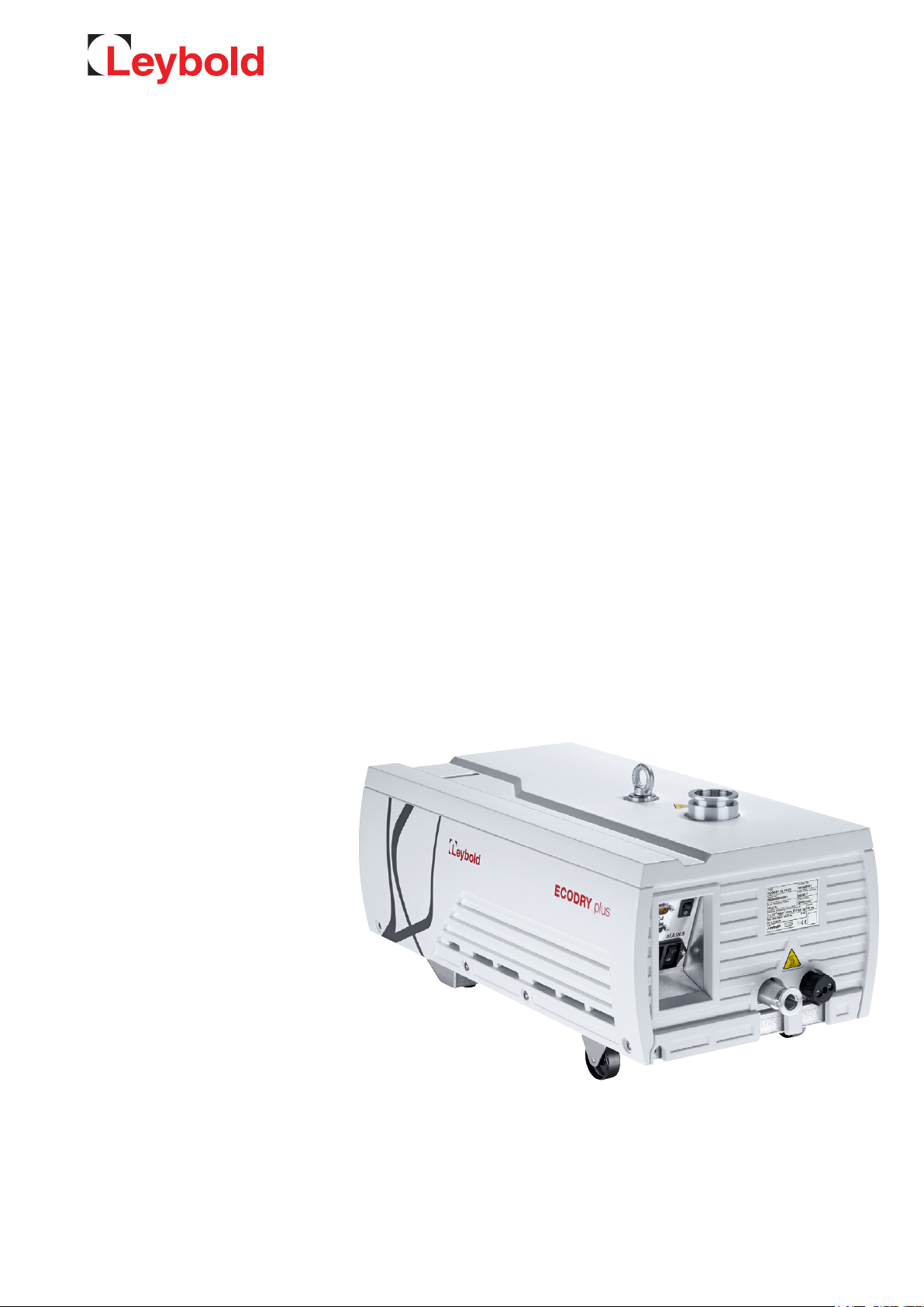
ECODRY plus
Multi-stage Roots vacuum pump
Operating Instructions 300758785_002_C1
Part Nos.
161040V21
161040V22
161065V21
161065V22
Page 2

Contents
Page
0 Important Safety Information 4
0.1 Mechanical Hazards 4
0.2 Electrical hazards 4
0.3 Thermal Hazards 4
0.4 Hazards Caused by Materials and Substances 4
0.5 Noise Hazard 5
1 Description 6
1.1 Supplied Equipment 6
1.2 Technical Data 6
1.2.1 Electrical Data 7
1.3 Ordering Data 8
1.4 Accessories 9
2 Transport and Storage 10
3 Installation 11
3.1 Placement 11
3.2 Conforming Use 11
3.2.1 Non-conforming Use 12
3.3 Connecting the Pump 13
3.4 Electrical Connection 14
4 Operation 15
4.1 Manual Operation 15
4.2 Interfaces 15
4.2.1 X1 Control Interface 15
4.2.2 X104 Serial RS-485 Interface 17
4.2.3 Frequency converter display 19
4.3 Gas Ballast 20
4.4 Switching off / Decommissioning 22
5 Servicing 23
5.1 Leybold Service 23
6 Troubleshooting 24
7 Waste Disposal 27
8 Certificates 27
EC Declaration of Conformity 28
Declaration of Contamination 29
2 300758785_002_C1 - 06/2019 - © Leybold
Page 3
Safety Information
Obligation to Provide Information
Before installing and commissioning the pump, carefully read these
Operating Instructions and follow the information so as to ensure optimum
and safe working right from the start.
The Leybold ECODRY plus has been designed for safe and efficient operation when used properly and in accordance with these Operating Instructions.
It is the responsibility of the user to carefully read and strictly observe all safety precautions described in this section and throughout the Operating
Instructions. Moreover, observe the information in all additionally supplied
Operating Instructions for switches or valves, for example.The pump must
only be operated in the proper condition and under the conditions described
in the Operating Instructions. It must be operated and maintained by trained
personnel only. Consult local, state, and national agencies regarding specific
requirements and regulations. Address any further safety, operation and/or
maintenance questions to our nearest office.
DANGER indicates an imminently hazardous situation which, if not avoided, will result in death or serious injury.
WARNING indicates a potentially hazardous situation which, if not
avoided, could result in death or serious injury.
NOTICE
DANGER
WARNING
CAUTION indicates a potentially hazardous situation which, if not avoided,
could result in minor or moderate injury.
NOTICE is used to notify users of installation, operation, programming or
maintenance information that is important, but not hazard related.
We reserve the right to alter the design or any data given in these Operating
Instructions. The illustrations are not binding.
Retain the Operating Instructions for further use.
CAUTION
NOTICE
These Operating Instructions are a translation of the original German
Operating Instructions 300758785_001_C1.
3300758785_001_C1 - 06/2019 - © Leybold
Page 4
Safety Information
0 Important Safety Information
0.1 Mechanical Hazards
WARNING
1 Avoid exposing any part of the human body to the vacuum.
2 Select a secure place for the appliance (level surface).
3 The discharge port of the pump must not be blocked or constricted.
Never operate the pump with a seal-off stopper in place blanking off
the exhaust port. Operate the pump only with a connected vacuum
system to the intake flange.
4 With a closed exhaust pipe, the pump can generate up to 5 bar pres-
sure (absolute) on the exhaust. The exhaust pipes should be laid out
according.
5 Condensates from the pump can collect inside or at the exhaust,
escape and spill onto the floor, when operating the pump without an
exhaust line or during transport with an exhaust being not blanked off.
In this case there exists the risk of slipping.
DANGER
CAUTION
DANGER
6 Due to its weight the pump must only be lifted by duly trained and
qualified persons.
0.2 Electrical hazards
1 Housing parts must not be opened.
2 Connect the appliance only to a properly and professionally installed
mains outlet socket with protective earth connection.
3 Note the information on the IP type of protection.
0.3 Thermal Hazards
1 At the crane eye, the intake flange and the exhaust flange, the pump
may attain temperatures over 80 °C. There is the risk of suffering
burns. Note the danger symbols on the pump itself.
0.4 Hazards Caused by Materials and Substances
1 Fluoropolymers are used as sealants (FKM) and as lubricants (PFPE) in
the pumps. In case the pump suffers a severe mechanical failure, it
cannot be ruled out that toxic and/or corrosive substances may be
released due to thermal decomposition. Do not open the pump module, and close off the inlet and exhaust flanges using blank flanges.
2 Before commissioning the pump, make sure that the media which are
to be pumped are compatible with each other so as to avoid hazardous situations. Observe the instructions for proper and improper use of
the pump in Section 3.2.
3 When pumping hazardous gases we recommend a leak search on a
regular basis. Leaks in the pump cannot be ruled out under all circumstances. When pumping hazardous gases, the operator must ensure
that that leaks at the pump will not be a hazard. When pumping toxic
gases replace the gas ballast switch with a plug screw or connect a
gas supply to the gas ballast.
4 300758785_002_C1 - 06/2019 - © Leybold
Page 5
Safety Information
4 If required additional monitoring of the gas ballast quantities is neces-
sary from the side of the operator when a well-defined and ensured
dilution is necessary from the side of the process. The type of protection depends on the specific process and needs to be assessed by of
the customer.
5 When the pump has been used to pump hazardous gases, introduce
appropriate safety precautions before opening the intake or the discharge connections. Before opening the pump, purge it for a longer
period of time with an inert gas. If necessary, wear suitable personal
protection equipment like gloves, breathing protection and protection
clothing, for example (see Material Safety Data Sheets for the substances in use, the chemical reactions and the by-products). Close off
the pump’s inlet and exhaust flanges using blank flanges.
6 When disposing of the pump, observe the applicable environment reg-
ulations.
0.5 Noise Hazard
1 The noise level of the pump during ultimate pressure operation corre-
sponds to the values stated in the technical data. In other operating
modes and depending on the connected vacuum system, higher values can be expected. Make sure that suitable protection measures are
taken to protect your hearing.
CAUTION
5300758785_001_C1 - 06/2019 - © Leybold
Page 6

Description
1 Description
The ECODRY plus is an eight-stage Roots pump. It is of the dry compressing
type and capable of evacuating chambers down to the medium vacuum
range.
The pump is connected to a single-phase supply using a mains power cable
and is powered via a built-in electronic drive unit. It is air-cooled. Bearings
and gears are lubricated using PFPE. The pump is therefore maintenancefree from the customer’s perspective.
1.1 Supplied Equipment
The pump is delivered ready for use, except from a power cable. Inlet and
exhaust flanges are closed. The scope of delivery includes:
■
2 centering rings, 2 clamping rings, 2 blank flanges for the inlet and
exhaust flanges
■
D-sub 9-pin jumper for manual operation of the pump.
1.2 Technical Data
ECODRY plus 40 65 Tolerance
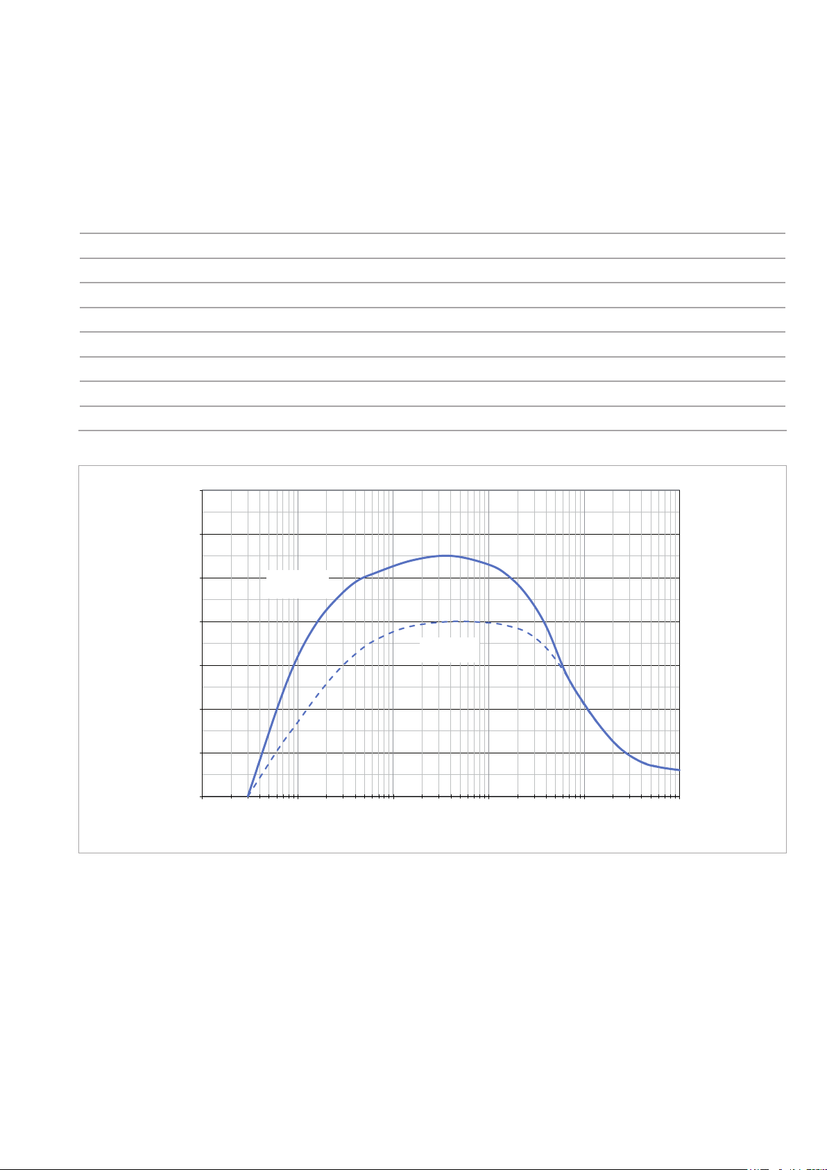
Maximum pumping speed without gas ballast 40 m³/h 55 m³/h ± 5 %
Ultimate partial pressure without gas ballast < 0.03 mbar
Ultimate partial pressure with gas ballast < 0.1 mbar
Maximum permissible inlet pressure 1050 mbar*
Max. perm. discharge pressure (relative to ambient) 200 mbar
Leak rate < 10
Water vapour tolerance with gas ballast 20 mbar 20 mbar
Water vapour capacity with gas ballast 300 g/h 500 g/h
Permissible ambient temperature +5 to +40 °C
Storage temperature -20 to +60 °C
Typical noise level without silencer, at ultimate pressure
(acc. to DIN EN ISO 2151)
Relative ambient atmospheric humidity 95%, non-condensing
Max. installation height up to 3000 m (NHN)*
-5
mbar∙l/s
< 52 dB(A)
Cooling Air
Leakage current in accordance with IEC 61010-1 < 3.5 mA
Max. contamination grade acc. to IEC 61010-1 2
Speed 12 600 RPM
Protection class IP 42
Intake flange DN 25 ISO-KF DN 40 ISO-KF
Discharge flange DN 16 ISO-KF
Weight, approx. 43 kg ± 1 kg
* For installation heights above 2000 m, an inlet pressure of 50 mbar should not be permanently exceeded.
6 300758785_002_C1 - 06/2019 - © Leybold
Page 7
Description
1.2.1 Electrical Data
ECODRY plus 120 V 200-240 V Tolerance
Rated voltage 120 V 200-240 V ± 10 %
Frequency 60 Hz 50/60 Hz ± 5 %
Network type TN
Phases 1-ph
Rated current 15 A 10 A
Rated power 1200 VA
Mains fusing / characteristic 15 A / slow blow 16 A / slow blow
Mains connection C 20 acc. to IEC 60320
70
60
50
/h]
3
/h)
3
40
30
Pumping speed [m
Saugvermögen (m
20
10
0
0,01 0,1 1 10 100 1000
Fig. 1.1 Typical pumping speed curves
ECODRY
65 plus
ECODRY
40 plus
Einlassdruck (mbar)
Inlet pressure [mbar]
7300758785_001_C1 - 06/2019 - © Leybold
Page 8
Description
160
287
191
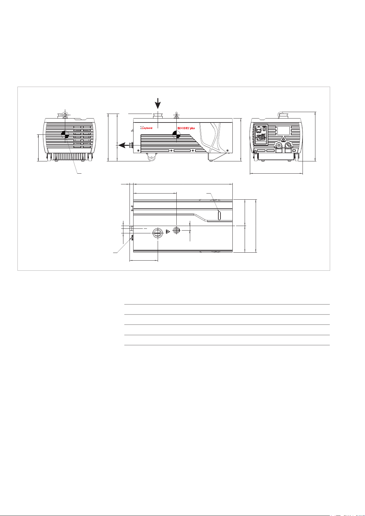
DN 16 ISO-KF
96
ECODRY 40 plus: DN 25 ISO-KF
ECODRY 65 plus: DN 40 ISO-KF
259
298
Center of
Schwerpunkt
gravity
Gas ballast
Gasballast
Fig. 1.2 Dimensional drawing, dimensions in mm
320
23
261
17
28
171
600
Display
160160
320
27
1.3 Ordering Data
Part No.
ECODRY 40 plus (120 V) 161040V21
ECODRY 65 plus (120 V) 161065V21
ECODRY 40 plus (200-240 V) 161040V22
ECODRY 65 plus (200-240 V) 161065V22
8 300758785_002_C1 - 06/2019 - © Leybold
Page 9

1.4 Accessories
Inlet screen
DN 40 ISO-KF E41 170 121
DN 25 ISO-KF E41 170 206
Mains cables
EU (CEE 7/7 - C19, 2.0 m) 161810 EU
UK (BS 1363 - C19, 2.0 m) 161810 UK
US cables
US 120 V (NEMA 5-15P - C19, 2 m) 141103US
US 200-240 V (NEMA 5-15P - C19, 2.5 m) 161810US
Blank flange, aluminium
DN 16 ISO-KF 184 46
DN 25 ISO-KF 184 47
DN 40 ISO-KF 184 48
Centering ring, aluminium, FPM
DN 16 ISO-KF 182 06
DN 25 ISO-KF 182 07
DN 40 ISO-KF 182 08
Clamping ring, aluminium
DN 16 ISO-KF 183 41
DN 25 ISO-KF 183 42
DN 40 ISO-KF 183 43
Casing assembly mounting kit 161 831 A
Plug screw gas ballast 161 832 A
Purge gas adapter 161 833 A
DN 16 ISO-KF/12 mm hose adapter for exhaust flange 182 90
RS485/USB connecting cable for X104 interface, 1.8 m 161 820 USB
LEYASSIST software 230 439 V01
Replacement control interface jumper X1 161 823 A
Description
9300758785_001_C1 - 06/2019 - © Leybold
Page 10

Transport and Storage
2 Transport and Storage
For transportation lift the pump at the crane eye or safely secured on a suitable pallet.
The pump must not be tilted more than 30 degrees during transport.
For transports over short distances slightly lift the pump at the front side and
move it to the desired location.
Storage
Store the pumps only horizontally standing on their feet and castors.
The pump has been blanked off with blank flanges. Open the pump only
immediately before installing it.
Until putting the pump into service, store the pump in a dry place preferably
at room temperature blanked off with the supplied blank flanges.
The pump must be stored at the most for one year only. Longer storing without turning the rotors will damage the bearings. Therefore, if you are storing
the pump for longer periods, it should be run once a year for at least 45 minutes and then returned to storage, as described in the following sections.
(The intake flange can stay sealed during this brief operation, the exhaust
flange must be opened.)
10 300758785_002_C1 - 06/2019 - © Leybold
Page 11
Installation
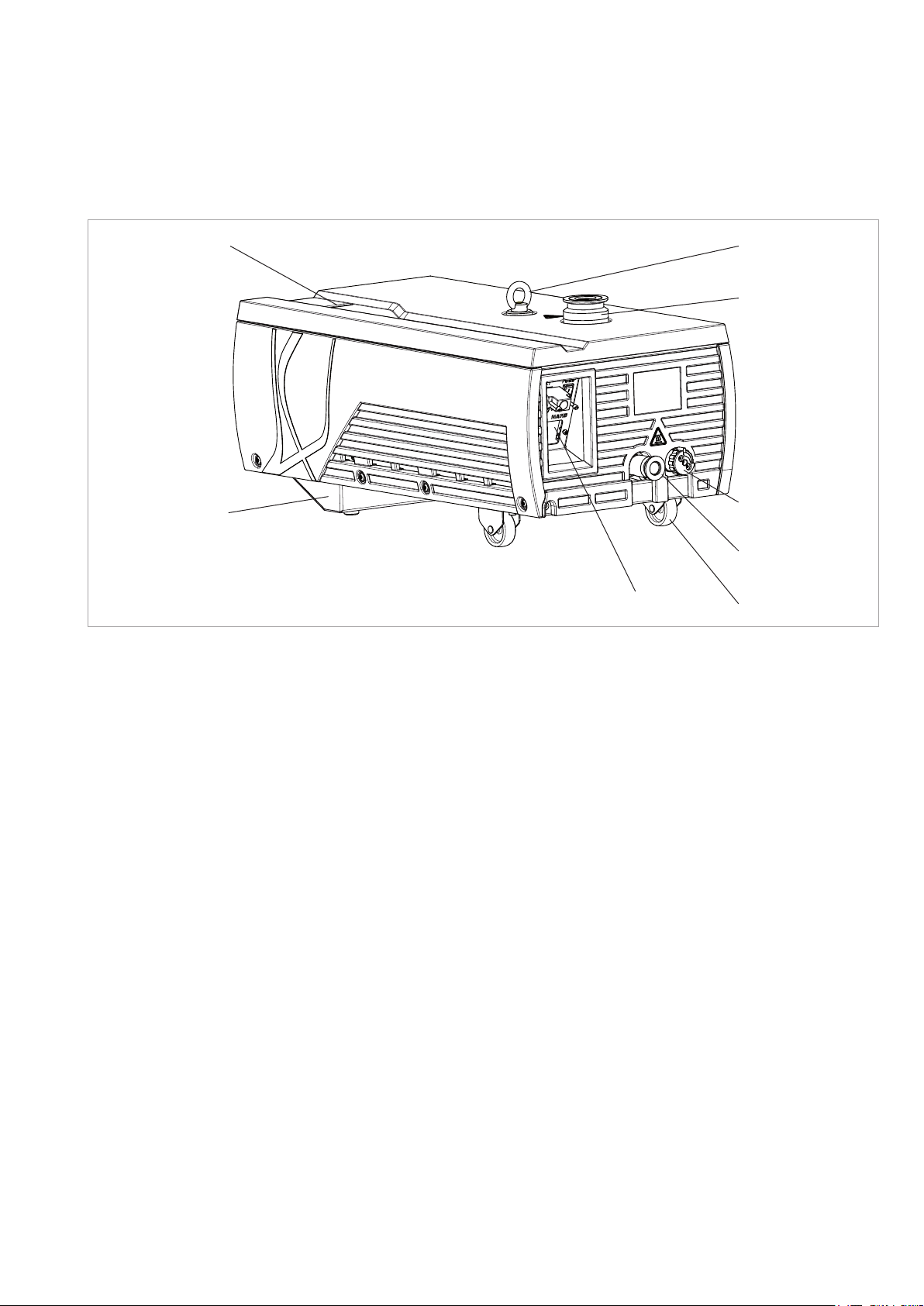
Display of the
frequency converter
Foot
Fig. 3.1 Connections and controls
3 Installation
See fig. 3.3
Crane eye
Intake flange
Gas ballast switch
Exhaust flange
Castors
3.1 Placement
Place the pump on a straight and level surface (max. tilt of 2°).
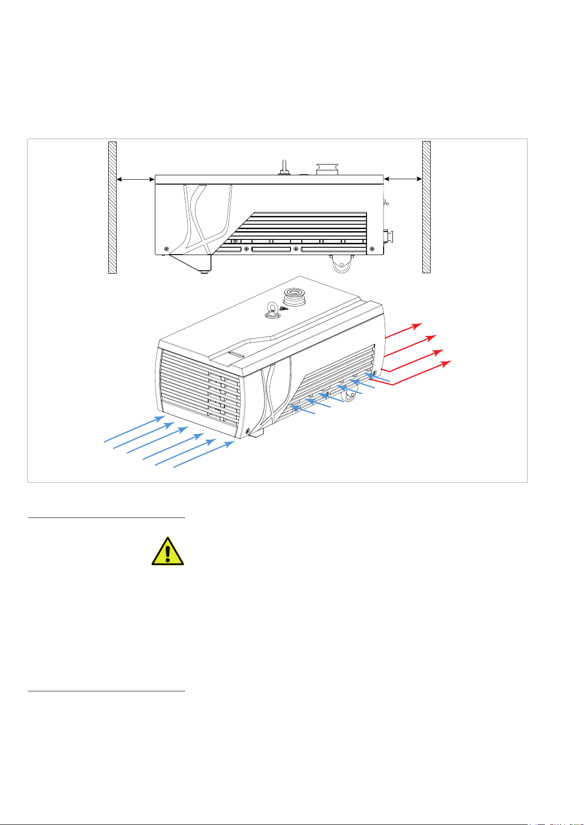
To ensure sufficient cooling of the pump, the fan openings of the pump must
not be obstructed, see fig. 3.2.
3.2 Conforming Use
The ECODRY plus has been designed to produce a vacuum. It is capable of
pumping clean, dry gases, which are free of particles, like air, nitrogen, oxy-
gen ≤ 21%, argon with inlet pressure < 100 mbar and helium. Moreover, it is
capable of evacuating vessels of vacuum systems down to the medium vacuum range.
The pump is suited for deployment as a backing pump for turbomolecular
pumps.
Organic solvents may only be pumped in traces/at low concentrations (consult Leybold first) outside the flammability range. The pump is suited for
pumping water vapour within the limits given in the technical data.
11300758785_001_C1 - 06/2019 - © Leybold
Page 12
Installation
> 100 mm> 100 mm
Air temperature < 70 °C
Cooling air OUT
Fig. 3.2 Cooling air flow
Cooling air IN
DANGER
Cooling air IN
3.2.1 Non-conforming Use
The ECODRY plus is not suited for use in short cycle pump processes with
high repetition rates (pick-and-place, loadlock, for example).
The ECODRY plus is not suited for pumping of:
■ Radioactive substances
■ Explosive substances
■ Ignitable gas mixtures
■ Pyrophorous gases
■ Liquids
■ Media condensing in the pump
■ Solids/dusts
■ Oxidative substances with the exception of ≤ 21% oxygen in the air
■ Toxic gases belonging to GHS category I and II*
Pumping of the following gases is only permissible after having consulted
Leybold first:
■ corrosive gases
■ toxic gases belonging to GHS category II and IV*
*Globally Harmonized System of Classification, Labelling and Packaging of Chemicals
12 300758785_002_C1 - 06/2019 - © Leybold
Page 13
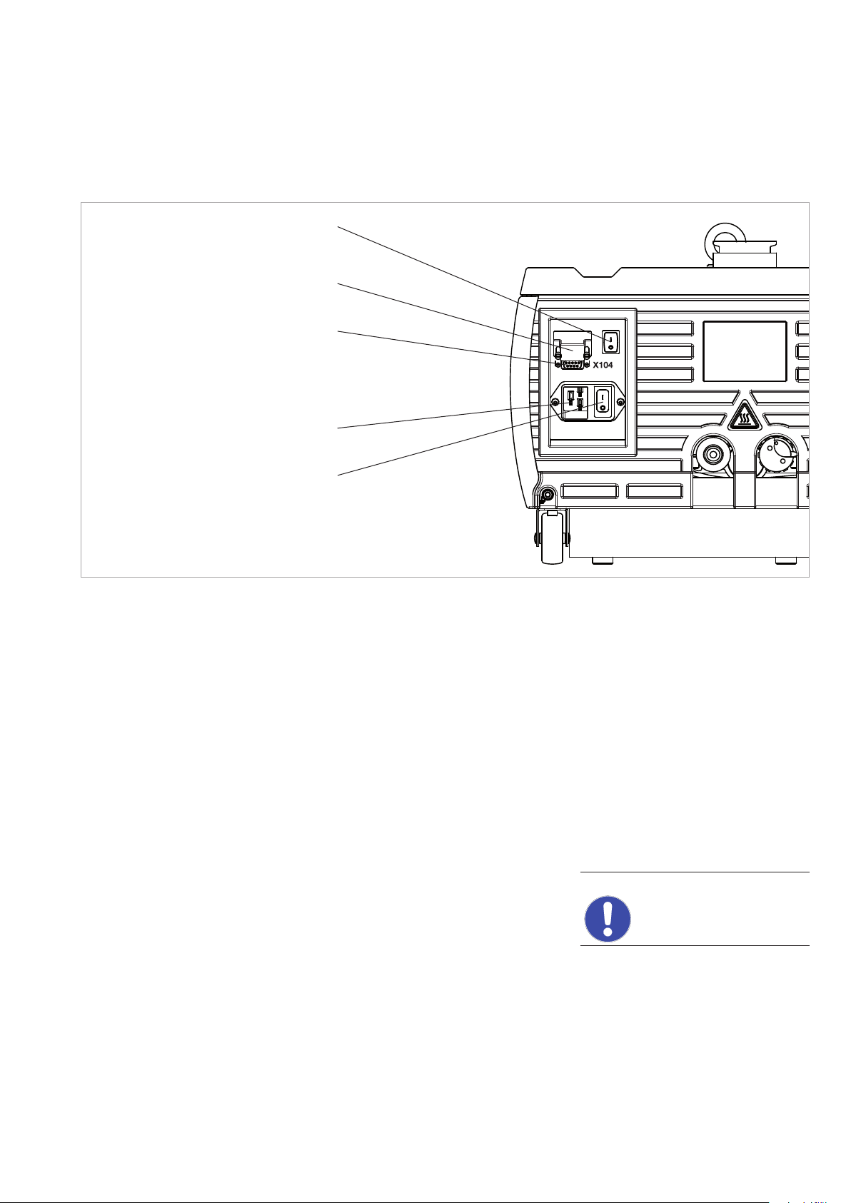
Start/Stop switch
Control interface X1
with bridging plug
Installation
RS 485 interface X104
Mains connection
Mains switch
Fig. 3.3 Connections and controls
When pumping toxic gases replace the gas ballast switch with a plug screw
or connect a gas supply to the gas ballast.
3.3 Connecting the Pump
Remove the blank flanges. We recommend that you retain the blank flanges
for decommissioning of the pump.
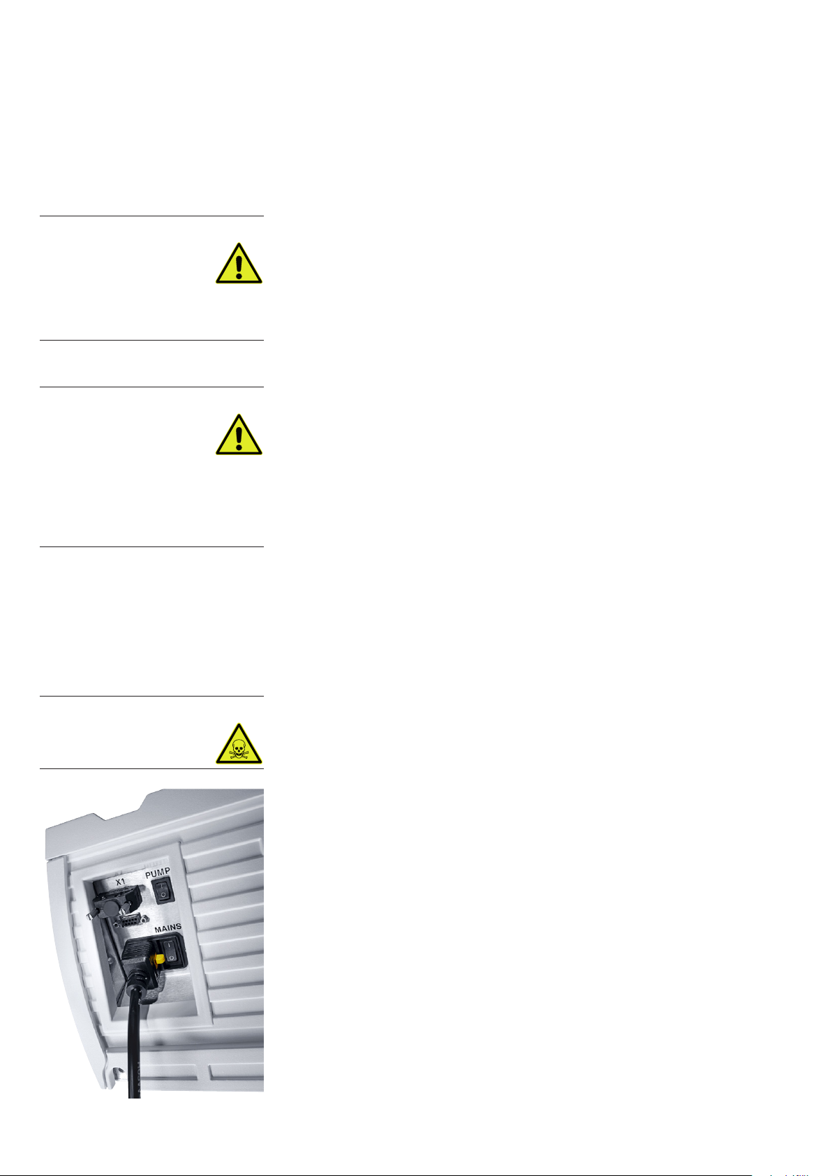
X1 PUMP
MAINS
During installation work on the intake and discharge lines do not subject
flanges to any stresses.
Intake side
At the intake side, connect a hose to the vacuum chamber. Do not damage
the sealing surfaces of the connecting flanges.
Do not allow the ingestion of any objects (screws, welding beads, nuts,
washers, pieces of wire, etc.) through the intake port of the pump.
The intake line must be clean. Deposits in the intake line can degas and
impair the vacuum. The connecting flanges must be clean and undamaged.
NOTICE
13300758785_001_C1 - 06/2019 - © Leybold
Page 14
Installation
Exhaust line
DANGER
CAUTION
Connect the exhaust line with a hose to the pump, or when operating the
pump without a connected exhaust line, operate the pump only in a well
ventilated room. The operator must check, whether the pumped gases will
lead to safety risks on the environment if the pump is operated without an
exhaust line (i.e. risk of suffocation, risk of slipping due to condensing
vapours, etc.).
The cross-section of the exhaust line must at least match the inside diameter
of the connections.
Smaller cross sections may cause an undesirable overpressure within the
system. Do not start up the pump with a constricted or blocked exhaust.
Ensure that any valves or blocking devices in the exhaust line are open.
Clogged exhaust lines will reduce the available pumping speed, increase
temperature and cause overloading of the pump motor or a dangerous
overpressure within the system. There is the risk of bursting. The pump
can generate pressures up to 5 bar (abs.) at the exhaust, when the discharge line is shut.
When pumping vapours we recommend connecting a condensate separator
at the exhaust.
The exhaust lines should be laid so that they drop down and away thereby
preventing condensate from flowing back into the pump. We recommend a
slope > 3°.
DANGER
Connect the exhaust line to an abatement system with sufficient throughput,
if required by the process.
If within the system toxic substances or gases are being used, then the
operator will be responsible for ensuring that the corresponding safety precautions are introduced!
3.4 Electrical Connection
Read the data on the device nameplate carefully before connecting to mains
voltage. Plug in the power connector.
The pump is only intended for a TN systems network. For other types of networks please contact Leybold.
When using a residual current device (RCD) install type B or type F.
The plug is equipped with a cable pull-out protection. When plugging in the
mains plug, the pull-out protection mechanism engages. To pull out, press
finger on the yellow release lever, which will release the locking mechanism
again.
If required, connect the X1 control interface or the X104 RS 485 interface
(see Section 4.2).
14 300758785_002_C1 - 06/2019 - © Leybold
Page 15
4 Operation
The ECODRY plus can be operated either manually or via an interface.
Operation
Switch the pump only on provided an exhaust line has been connected.
The exhaust of the pump must not be blocked or constricted. Never operate the pump with the seal-off stoppers in place blanking off the exhaust
port.
4.1 Manual Operation
For manual operation, connect the jumper supplied with the unit to the X1
interface.
Switch the pump on at the MAINS switch and wait for approximately two
seconds while the pump initialises. Now the pump can be started using the
start/stop switch (PUMP).
Following start-up, the pump requires a few seconds in order to reach its
rated frequency.
In this mode, the X104 interface can only be used for reading off operating
parameters.
4.2 Interfaces
4.2.1 X1 Control Interface
The pump can be incorporated within a plant control system by means of the
X1 control interface. To do this, set the start/stop (PUMP) switch to “1”. The
ECODRY plus can be started remotely by closing the pin 8 contact to pin 9
on the X1 interface. Opening the contact stops the unit.
WARNING
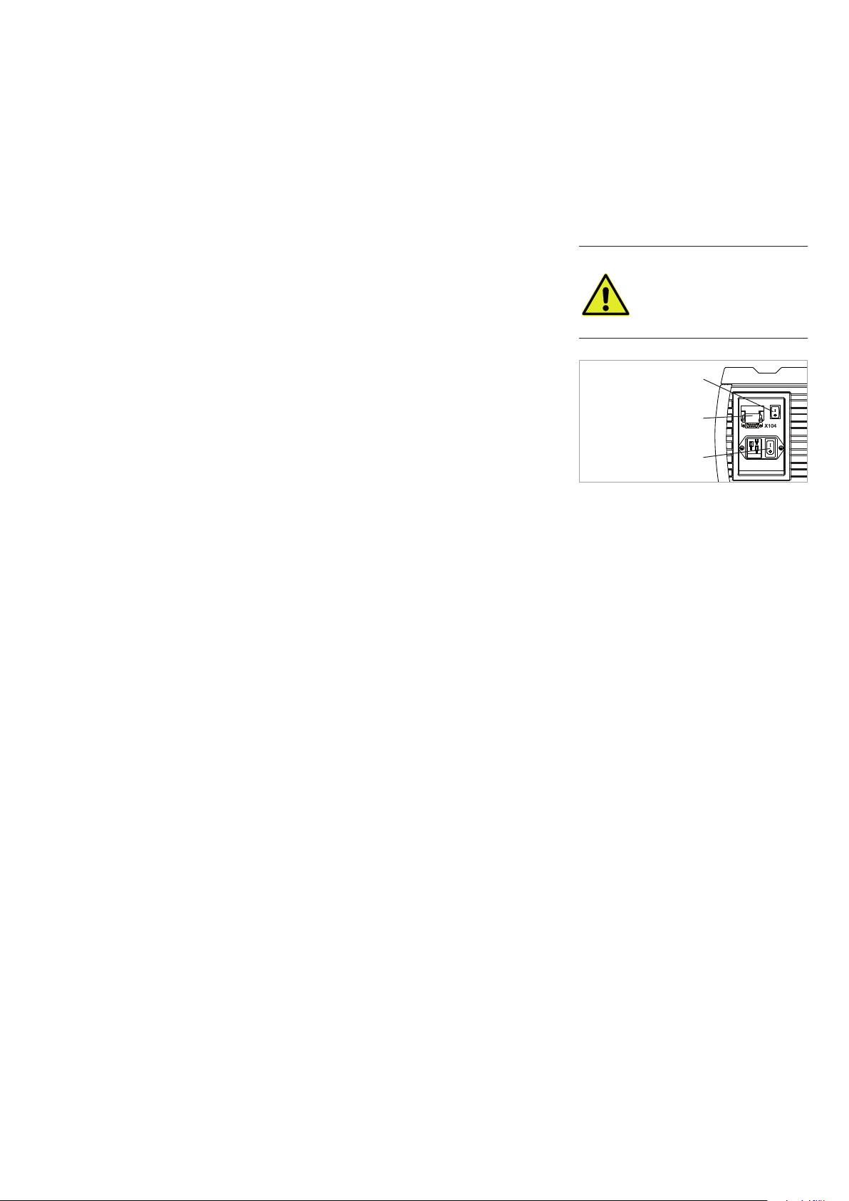
Start/Stop switch
X1 PUMP
Bridging plug
MAINS
Mains switch
In this mode, the X104 interface can only be used for reading off operational
parameters.
15300758785_001_C1 - 06/2019 - © Leybold
Page 16
Operation
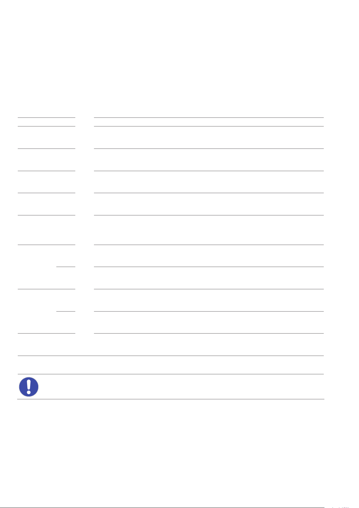
Table: Pin assignment X1
Customer plug (provided with pump)
SUB-D 9 (female)
Description Pin Pin Description Limits Function
1 1
2 2
3 3
4 4 Digital Common
5 5
Jumper Pin 6
/ Pin 7: speed
control
deactivated
6 6
7 7 Analog Common
ECODRY plus X1
SUB-D 9 (male)
Analog Frequency
Monitor output
Digital Input / Low
speed
Voltage supply for
analog input
Digital Output
(Pump Status)
Analog Input
(Speed Control)
Analog signal proportional to cur-
0 … +10 Vdc (2 mA)
low active input (ref. to Digital
Common)
+10.5 V (max. 16 mA) Voltage supply for analog input A1
Optocoupler output open collector (supply by single resistor,
max. current 10 mA) (low active
ref. to optocoupler ground)
0 … +10 V
(20 kOhm)
rent rotation frequency
(10 V = 210 Hz)
Bridge to pin 4 for lower speed
(170 Hz),
open for full speed (210 Hz)
On: Frequency setting reached
Off: Frequency setting not reached
Optional input, deactivated by
default*. Contact Leybold for
further information.
Jumper Pin 9
/ Pin 8: Run
Switch active
* When speed control is activated, operation is only possible if a voltage is applied between pins 6 and 7.
10 V correspond to maximum speed.
NOTICE: Do not apply external voltage to the digital input terminals because the internal optocouplers can be
damaged.
Do not exceed the stated voltage and current limits.
8 8 Digital Common
9 9
Hous-
ing
Hous-
Digital Input /
RUN
Pump housing,
ing
PE
low active input related to digital common
Bridge to pin 8 for RUN,
open for STOP
16 300758785_002_C1 - 06/2019 - © Leybold
Page 17
4.2.2 X104 Serial RS-485 Interface
Alternatively, the X104 RS 485 interface can be used to operate the pump,
giving access to additional operational parameters for the frequency converter.
The operating parameters can be accessed via MODBUS protocol or via the
LEYASSIST software (see Section 1.4. Accessories).
The following connection parameters are used for communication:
Protocol Modbus RTU
Baud rate 9600 bps
Data length 8 bit
Parity No parity
Stop bit 1 bit
Operation
Address 1
Modbus Register List
Description Read/
Write
Run Command Write 2000H Bit 1~0
Frequency Command (Hz) Read 2102H
Frequency Command (Hz) Write 0400H
Output Frequency (Hz) Read 2103H
Output Current (A) Read 2104H
Output Voltage (V) Read 2106H
DC Bus Voltage (V) Read 2105H
Modbus
Register
Settings
Bit 5~4 Always set to: 01B: FWD
Bit 14~13
All other bits set to zero.
01B: Stop
10B: Run
Run command source:
00B: No function
01B: Digital keypad
10B: Operated by 00-21 Setting
11B: Change operation source
Output Power (kW) Read 210FH
AC motor status:
00B: Drive stops
Drive Status Read 2101H Bit 1~0
Source of operation command Write 0015H
Error code Read 2100H Error codes listed in section „Troubleshooting“
Reset Write 2002H Set Bit 1 to 1 for Reset
1: External terminals
2: RS485 Communication
01B: Drive decelerating
10B: Drive standby
11B: Drive operating
17300758785_001_C1 - 06/2019 - © Leybold
Page 18
Operation
Description Read/
Write
Temperature of drive power module (°C) Read 220EH
Accumulated Run time (minutes) Read 051FH
Accumulated Run time (days) Read 0520H
Software revision/version Read 0006H
Modbus
Register
Settings
Table: Pin assignment serial interface X104
Customer plug
SUB-D 9 (male)
Description Pin Pin Description Comment
1 1 Not connected
Bridge to Pin 3 for
termina tion
Bridge to Pin 2 for
termina tion
GND 5 5 Ground (GND)
2 2 Termination
3 3 Termination
4 4 Not connected
ECODRY plus Serial Interface X104
SUB-D 9 (female)
6 6 Internally bridged w/ Pin 8
Tx/Rx+ 7 7 Receive + (Tx/Rx+) Bridged internally to Pin 9
Tx/Rx– 8 8 Send – (Tx/Rx–) Bridged internally to Pin 6
9 9 Internally bridged w/ Pin 7
Shield
Hous-
ing
Hous-
ing
Grounded
18 300758785_002_C1 - 06/2019 - © Leybold
Page 19
4.2.3 Frequency converter display
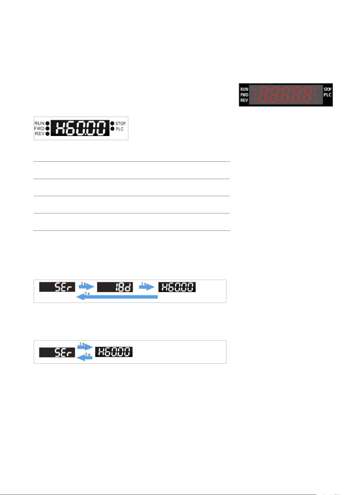
After switching on the FC, the display will show the output frequency in Hz
with a preceeding „H“.
E.g.: the pump motor runs at 60 Hz
There are several LEDs to indicate the different pump‘s states:
STOP LED Flashing: Drive is in a warning mode.
On: Drive is in an error mode and the pump is being stopped.
REV LED On: Motor runs reverse
Off: Motor rotates forward
FWD LED On: Pump is ready or is running.
Off: Drive is in initialisation mode.
RUN LED Output frequency is shown in the display..
On: Drive is running.
Operation
Approx. 1,000 hours before reaching the recommended service interval, the
display will show the warning message „SEr“ and the remaining time indicated by a „d“ (for days).
The displays change constantly every 3 seconds:
If the recommended service interval is exceeded, the display toggles between
showing the frequency and the warning message „SEr“.
The displays change constantly every 3 seconds:
19300758785_001_C1 - 06/2019 - © Leybold
Page 20
Operation
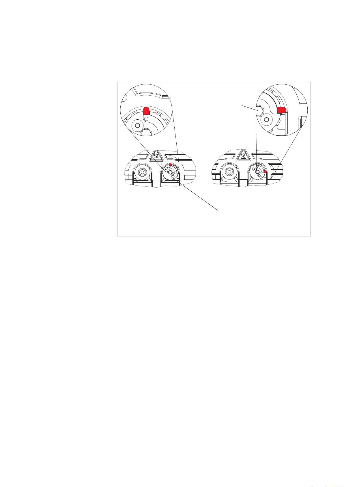
Hexagon socket for
unscrewing the gas
ballast switch
Gas ballast closedGas ballast open
Gasballast geschlossenGasballast geöffnet
The operating area of the gas ballast switch can
be distorted contrary to the depiction.
Fig. 3.4 Gas ballast switch
4.3 Gas Ballast
If the process contains mainly permanent gases, the ECODRY plus may be
operated without gas ballast.
If the composition of the gases to be pumped is not known and if condensation in the pump cannot be ruled out, run the pump with the gas ballast valve
open.
Pumping of Condensable Gases and Vapours
If the gas ballast valve is open when the temperature is at operating level, the
ECODRY plus can pump water vapour within the limits specified in the technical data. If the vapour pressure rises above the permitted water vapour tolerance, the gasses condense to vapour in the pump.This can lead to corrosion and thus damage to the pump.
Before pumping out vapours, open the gas ballast valve and warm up the
pump for around 30 minutes with the inlet line closed.
Running under gas ballast has a detrimental effect on the ultimate pressure
which can be achieved.
20 300758785_002_C1 - 06/2019 - © Leybold
Page 21

Operation
After a pumpdown cycle leave the pump to operate for at least 30 minutes
approx. with the gas ballast open and the intake line closed until it is dry
again.
With the gas ballast valve opened the vacuum vessel will be vented in the
event of a power failure.
Swapping out the gas ballast switch
The gas ballast switch can be swapped for a solenoid valve or a purge gas
connector.
To do this, unscrew the gas ballast switch from the pump using a 6 mm Allen
key.
Then, screw in a suitable solenoid valve or purge gas connector with a quarter-inch thread. Max torque = 8 Nm.
Following assembly, check for leaks in the pump in order to ensure optimum
vacuum performance.
When connecting a gas supply to the gas ballast, reduce the pressure to 0.5
bar(g).
NOTICE
21300758785_001_C1 - 06/2019 - © Leybold
Page 22
Operation
4.4 Switching off / Decommissioning
Switching off
Stop the pump using the start/stop switch or via an interface. If the pump is
to be disconnected from the supply voltage, switch off the mains switch.
If the gas ballast valve is closed, rapid ventilation of the attached vacuum
vessel and damage to any turbomolecular pump which may be attached are
prevented by means of a check valve.
Decommissioning
If the pump is to be decommissioned for an extended period of time, the
pump should first be run dry and then evacuated.
The pump should then be switched off and removed from the system.
DANGER
When the pump has been used to pump hazardous gases, introduce
appropriate safety precautions before opening the intake or the discharge
connections.
Close off the inlet aperture using the blank flange supplied with the unit.
Leave the outlet flange open or, if necessary, connect it to a suitable
exhaust system.
Start the pump and, with the gas ballast switch open, let it run for at least
30 minutes.
Thereafter, close the gas ballast switch and run the pump for a further
5 minutes.
Then, stop the pump and leave it connected to the power supply for
another few minutes to cool down (the ventilator continues to run).
Next, close off the pump’s outlet aperture using the blank flange supplied
with the unit, switch of the MAINS switch and remove the mains plug.
22 300758785_002_C1 - 06/2019 - © Leybold
Page 23
5 Servicing
The pump is maintenance-free. We recommend that a precautionary service
(an overhaul at the Leybold Service Centre) be carried out after 35,000 hours
of operation or after five years of service life at the latest, whichever occurs
sooner. The pump is fitted with a counter for this purpose, which shows the
remaining number of days of operation until the next recommended service
on the pump’s display. For a long pump life we recommend regular service
by Leybold.
The recommended service intervals refer to continuous operation with inlet
pressures below 50 mbar and the pumping of non-condensable gases. In
case of frequent operation above 50 mbar, frequent pumping cycles or when
pumping condensing gases, we recommend shortening the service intervals.
Please contact Leybold.
1000 hours before reaching the recommended service interval, the display
will show the message SEr alternating with the down-counting hours remaining and the current speed. If the recommended service interval is exceeded,
the message toggles between SEr and the current speed.
Service
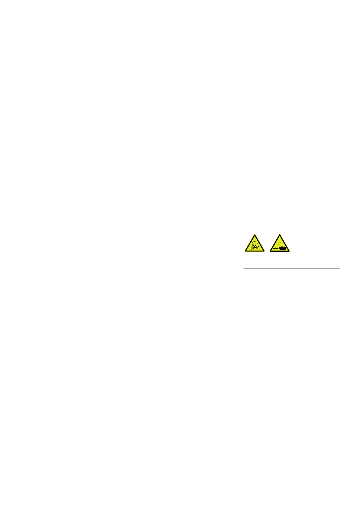
Within the pumps, fluoropolymers are used as a sealant (FKM) and as a
lubricant (PFPE). In case the pump suffers severe mechanical damage, it
cannot be ruled out that toxic and/or corrosive substances may be
released due to thermal decomposition. Do not open the pump module,
and close off the inlet and exhaust flanges using blank flanges.
The pump is equipped with EMC devices on the input side. Observe this
during device tests/commissioning.
5.1 Leybold Service
Whenever you send us in equipment, indicate whether the equipment is contaminated or is free of substances which could pose a health hazard. If it is
contaminated, specify exactly which substances are involved. You must use
the form we have prepared for this purpose.
A copy of the form has been reproduced at the end of these Operating
Instructions: “Declaration of Contamination for Compressors, Vacuum Pumps
and Components”. Another suitable form is available from www.leybold.com
-> Downloads -> Download Documents.
Attach the form to each pump.
This statement detailing the type of contamination is required to satisfy legal
requirements and for the protection of our employees.
DANGER
We must return to the sender any equipment which is not accompanied by a
contamination statement.
23300758785_001_C1 - 06/2019 - © Leybold
Page 24

Troubleshooting
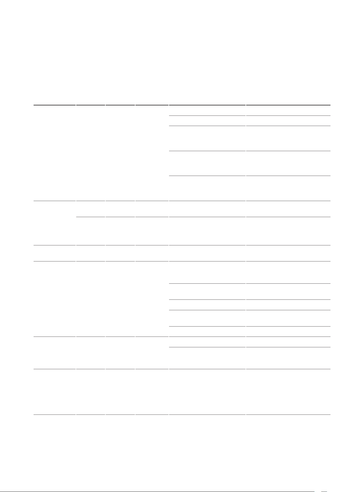
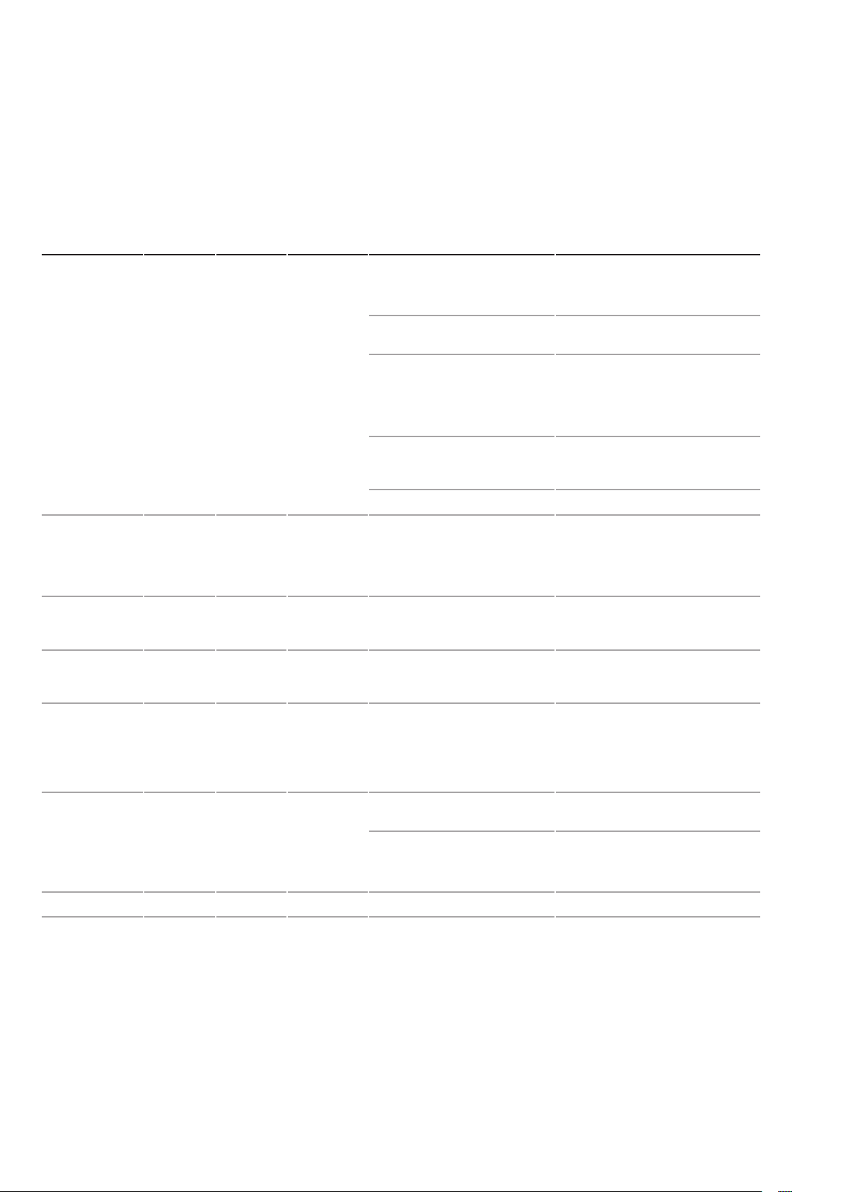
6 Troubleshooting
Faults and alarms indicate problems in the frequency converter or in the
pump.
An alarm (warning) is indicated by a code on the display and the flashing
STOP LED. The frequency converter output is not necessarily switched off,
the pump is not necessarily stopped.
A fault is indicated by a code on the display and the permanently lighting
STOP LED. The frequency converter output is always switched off immediately and the pump coast to stop.
To reset an alarm or an error, first find the cause for it. Remedy it and then
switch the Start/Stop switch to Stop. Then switch the mains switch off.
Wait for a few seconds until the display goes out and then switch the mains
switch on again, and thereafter switch the Start/Stop switch to Start.
This lists up the most important alarms and faults only. For further error messages please contact the Leybold service.
24 300758785_002_C1 - 06/2019 - © Leybold
Page 25
Troubleshooting
Malfunction Error
message
End pressure will
not be reached.
Error message in
the display
–
SEr
ocA
ocd
ocn
Pump is
extremely loud.
–
Error
code
(MODBUS)
1
2
3
Brief Description
– Gas ballast valve open Close gas ballast valve, if possible.
Service
Alarm
Overcurrent Short circuit or earthing fault
– Bearing defective Contact Leybold Service.
Likely cause Remedy
Leakage in the system Check for leak.
Gas ballast valve defective Check for leak.
Replace gas ballast valve – please
send us your enquiry.
Outlet blocked
Unacceptably high back pres-
sure in outlet
Pump does not run at the
rated rotational speed of 210
Hz.
Pump service countdown has
expired.
on the output side of the frequency converter
Ensure the pump outlet is clear.
Ensure that outlet pressure does
not exceed 1200 mbar.
Set target speed of 210 Hz (using
X104 RS-485 interface).
Contact Leybold Service.
Pump service required.
Contact Leybold Service.
Pump switches
off
Pump switches
off
Pump switches
off
oH 1
oH 3
oL
EoL 1
Lun
16
24
21
22
13 DC Under-
Heatsink
Overheat
Motor
Overload
voltage
Ambient temperature too high Set the pump up at a suitable
location with a lower ambient temperature.
Cooling air supply or discharge
impeded
Ventilator defective Contact Leybold Service.
Pump cooling fins blocked by
dirt
Gas temperature too high Check the system.
Bearing defective Contact Leybold Service.
Foreign bodies, particles or
process deposits are blocking
the rotor.
The voltage on the DC bus fell
for longer than two seconds.
(The power supply dropped or
is too weak.)
Ensure sufficient cooling air supply
or discharge.
Contact Leybold Service.
Contact Leybold Service.
Check the power supply.
Ensure that the power supply is
sufficiently strong.
Remove the pump from the mains
supply for at least 10 seconds and
restart.
25300758785_001_C1 - 06/2019 - © Leybold
Page 26
Troubleshooting
Malfunction Error
message
Pump does not
start.
Pump does not
start.
Pump does not
start or switches
off.
–
LuS
LuS
Error
code
(MODBUS)
14 DC Under-
14 Controller
Brief Description
– No mains voltage present Check mains power supply.
voltage or
Controller
Undervoltage“
Undervoltage
Likely cause Remedy
Set the mains switch on the pump
to 1.
Mains cable defective or not
correctly inserted
If operating using the start-stop
switch: the plug supplied is not
connected to the X1 control
interface, or pins 8 and 9 are
not bridged.
If operating using the X1 control interface: start-stop button
is not set to “start”.
Drive defective Contact Leybold Service.
Input voltage too low Compare the voltage range on the
Voltage too low for controlling
the frequency converter
Check the pump’s power supply.
Connect the plug supplied, with a
bridge between pins 8 and 9, to
the X1 control interface.
Set start-stop switch to “start”.
pump’s nameplate with the available mains voltage, and connect
the pump to a power supply at the
correct voltage.
Disconnect the pump from the
mains for at least 10 seconds and
restart.
Pump does not
start or switches
off.
Pump does not
start or switches
off.
Pump does not
reach nominal
speed 210 Hz
Others Contact Leybold Service.
LuS
oud
oun
–
14 DC Charge
Circuit Fault
8
9
DC Overvoltage
– Inlet pressure > 50 mbar Close the pump inlet and check
Charging circuit for DC bus is
defective.
DC bus voltage was too high.
The rundown time is too short.
Unstable motor controller
Input voltage is too high.
Outlet blocked
Unacceptably high back pres-
sure in outlet
Disconnect the pump from the
mains for at least 10 seconds and
restart.
Compare the voltage range on the
pump’s nameplate with the available mains voltage, and connect
the pump to a power supply at the
correct voltage.
the rotational speed on the display.
Ensure the pump outlet is clear.
Ensure that outlet pressure does
not exceed 1200 mbar.
26 300758785_002_C1 - 06/2019 - © Leybold
Page 27
Disposal / Certificates
7 Waste Disposal
The pump may have been contaminated by the process or by environmental
influences. In this case the equipment must be decontaminated in accordance with the relevant regulations. We offer this service at fixed prices.
Further details are available on request.
Contaminated parts can be detrimental to health and environment. Before
beginning with any work, first find out whether any parts are contaminated.
Adhere to the relevant regulations and take the necessary precautions
when handling contaminated parts.
Separate clean pumps according to their materials, and dispose of these
accordingly. We offer this service. Further details are available on request.
When sending us a pump, observe the regulations given in the Section
“Leybold Service”.
8 Certificates
The ECODRY have been tested by the TÜV Rheinland of North America
according to the requirements of
■
IEC 61010-1:2010 (Third Edition)
■
UL 61010-1:2012
CAN/CSA-C22.2
The TÜV Rheinland of North America is a “Nationally Recognized Testing
Laboratory” (NRTL) for the USA and Canada.
WARNING
27300758785_001_C1 - 06/2019 - © Leybold
Page 28
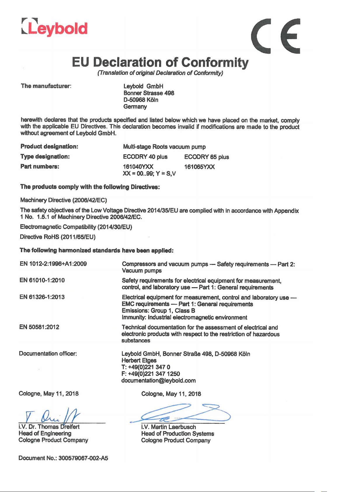
EC Declaration of Conformity
28 300758785_002_C1 - 06/2019 - © Leybold
Page 29
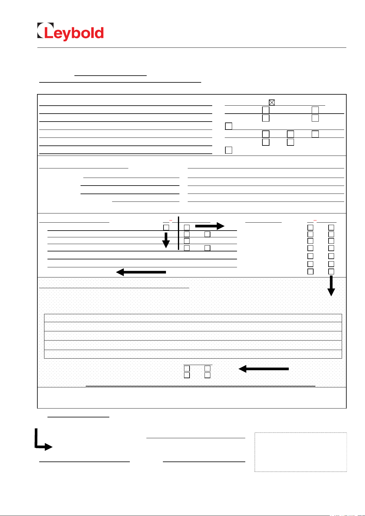
Declaration of Contamination of Compressors, Vacuum Pumps and Components
The repair and / or servicing of compressors, va cuum pumps and components will be carried out only if a correctly completed declaration has
been submitted. Non-completion will result in delay
A separate declaration has to be completed for each single component.
. The manufacturer can refuse to accept any equipment without a declaration.
Declaration of Contamination
This declaration may be completed and signed only by authorized and qualified staff.
Customer/Dep./Institute : Reason for return: applicable please mark
Address : Repair: chargeable warranty
Exchange: chargeable warranty
Person to contact: Return only: rent loan for credit
Phone : Fax: Calibration: DKD Factory-calibr.
End user: Quality test certificate DIN 55350-18-4.2.1
A. Description of the Leybold product:
Material description :
Catalog number: Additional parts:
Serial number: Application-Tool:
Type of oil (ForeVacuum-Pumps) : Application- Process:
B. Condition of the equipment
. Has the equipment been used
11.
2. Drained (Product/service fluid)
3. All openings sealed airtight
4. Purged
If yes, which cleaning agent
and which method of cleaning
1)
If answered with “No”, go to D. other harmful substances
No1) Yes No Contamination : No1) Yes
toxic
radioactive
microbiological
Failure description:
corrosive
flammable
explosive 2)
Exchange already arranged / received
2)
2)
C. Description of processed substances (Please fill in absolutely)
1. What substances have come into contact with the equipment ?
Trade name and / or chemical term of service fluids and substances processed, properties of the substances
According to safety data sheet (e.g. toxic, inflammable, corrosive, radioactive)
X Tradename: Chemical name:
a)
b)
c)
d)
No Yes
2. Are these substances harmful ?
3. Dangerous decomposition products when heated ?
If yes, which ?
2)
Components contaminated by microbiological, explosive or radioactive products/substances will not be accepted without written
evidence of decontamination.
D. Legally binding declaration
I / we hereby declare that the information supplied on this form is accurate and sufficient to judge any contamination level.
Name of authorized person (block letters) :
Date signature of authorized person
firm stamp
17200001_002_C0
© Leybold
29300758785_001_C1 - 06/2019 - © Leybold
Page 30

Leybold GmbH
Bonner Strasse 498
50968 Cologne
GERMANY
T: +49-(0)221-347-0
[email protected]
www.leybold.com
LV_21064_2019 06.19
 Loading...