


Phoenix Quadro
Table of contents
 Loading...
PHOENIX Quadro
PHOENIX Quadro dry
Helium leak detector
Operating instructions
300700189_002_C1
Catalog Numbers
250000V02 (EU)
251000V02 (US)
251100V02 (JP)
250001V02 (dry, all countries)

Table of Contents LEYBOLD
ii PHOENIX-Quadro-Operating-instructions-300700189_002_C1-(1801)
Table of Contents
1 About these instructions ...................................................................................................................................6
1.1 Target groups ...........................................................................................................................................6
1.2 Warnings...................................................................................................................................................6
2 Safety ...............................................................................................................................................................7
2.1 Intended use .............................................................................................................................................7
2.2 Owner requirements .................................................................................................................................7
2.3 Duties of the operator ...............................................................................................................................8
2.4 Dangers ....................................................................................................................................................8
3 Shipment, Transport, Storage ........................................................................................................................10
4 Description......................................................................................................................................................13
4.1 Function ..................................................................................................................................................13
4.2 Operation modes ....................................................................................................................................13
4.2.1 Operation mode “Vacuum”.......................................................................................................... 13
4.2.2 Operation mode “Sniffing”........................................................................................................... 13
4.3 Device setup ...........................................................................................................................................14
4.3.1 Overall device .............................................................................................................................14
4.3.2 Operating unit ............................................................................................................................. 15
4.3.2.1 START button ....................................................................................................................16
4.3.2.2 STOP button ......................................................................................................................16
4.3.2.3 ZERO button ......................................................................................................................17
4.3.2.4 Meaning of the button LEDs...............................................................................................17
4.3.2.5 Meaning of the status LED.................................................................................................18
4.3.2.6 Assembly of the touchscreen .............................................................................................19
4.3.3 Vacuum connections................................................................................................................... 20
4.3.3.1 Inlet ....................................................................................................................................20
4.3.3.2 Exhaust ..............................................................................................................................21
4.3.3.3 Connection for venting and purging/gas ballast .................................................................21
4.3.4 Connections for accessories and control signals........................................................................ 23
4.3.5 Markings on the device ...............................................................................................................24
4.4 Technical data ........................................................................................................................................24
5 Installation ......................................................................................................................................................27
5.1 Setup ......................................................................................................................................................27
5.2 For oil-sealed backing pumps, remove the plug .....................................................................................29
5.3 Connecting the leak detector to the power supply system .....................................................................29
5.4 Check the Operation of the Device.........................................................................................................30
6 Operation........................................................................................................................................................32

LEYBOLD Table of Contents
PHOENIX-Quadro-Operating-instructions-300700189_002_C1-(1801) - © Leybold GmbH iii
6.1 Switch ON...............................................................................................................................................32
6.2 Basic settings..........................................................................................................................................32
6.2.1 Set language on the user interface .............................................................................................32
6.2.2 Setting date, time and time zone ................................................................................................ 33
6.2.3 User profile settings ....................................................................................................................33
6.2.3.1 Overview of Rights Groups ................................................................................................33
6.2.3.2 Select, modify, create user profile......................................................................................33
6.2.3.3 Modify Personal Settings ...................................................................................................34
6.2.4 Switch off Automatic Login.......................................................................................................... 35
6.2.5 Switch on Automatic Login.......................................................................................................... 35
6.2.6 Presentation of the measurement screen ...................................................................................36
6.2.6.1 Changing the presentation of the line graph ......................................................................36
6.2.6.2 Changing the presentation of the bar graph.......................................................................37
6.2.6.3 Change general display settings ........................................................................................37
6.2.7 Change units............................................................................................................................... 38
6.2.8 Change audio settings ................................................................................................................38
6.2.9 Change the protection settings ...................................................................................................39
6.2.10 Activate or deactivate maintenance requests .............................................................................41
6.2.11 Modify Other Settings ................................................................................................................. 41
6.3 Settings for the measurements...............................................................................................................42
6.3.1 Select operation mode ................................................................................................................42
6.3.2 Select gas ...................................................................................................................................42
6.3.3 Setting setpoints ......................................................................................................................... 42
6.3.4 Change vacuum settings ............................................................................................................ 43
6.3.5 Setting the machine factor ..........................................................................................................44
6.3.6 Set external calibration leak........................................................................................................ 45
6.3.7 Change pressure limits ...............................................................................................................45
6.3.8 Set and use the function ZERO ..................................................................................................46
6.3.9 Change leak rate filter................................................................................................................. 47
6.3.10 Change background suppression ...............................................................................................47
6.3.10.1 Determine the background of the inlet area .......................................................................48
6.3.11 Change the sniffer line pressure monitoring ...............................................................................48
6.3.12 Set and use external partial flow system .................................................................................... 49
6.3.13 Calibrating ................................................................................................................................... 50
6.3.13.1 Internal calibration..............................................................................................................50
6.3.13.2 External calibration.............................................................................................................51
6.4 Measuring ...............................................................................................................................................52
6.5 Measurement data..................................................................................................................................53
6.5.1 Configure data recording ............................................................................................................ 53
6.5.2 Configure and implement export................................................................................................. 53
6.5.3 Measurement data database: Information and delete function................................................... 54
6.6 Information..............................................................................................................................................55
6.6.1 Retrieve information about the device ........................................................................................ 55
6.6.2 Call information on the assemblies .............................................................................................55

Table of Contents LEYBOLD
iv PHOENIX-Quadro-Operating-instructions-300700189_002_C1-(1801)
6.6.3 Information on connected accessories ....................................................................................... 55
6.6.4 Call the energy data information .................................................................................................55
6.6.5 Call the latest information to the current measurement value..................................................... 56
6.6.6 Call the latest information to the current calibration value ..........................................................56
6.7 Log..........................................................................................................................................................56
6.7.1 Call the error and warning log..................................................................................................... 56
6.7.2 Call the TMP log ......................................................................................................................... 56
6.7.3 Call calibration log....................................................................................................................... 56
6.7.4 Call maintenance log .................................................................................................................. 57
6.8 Device settings .......................................................................................................................................57
6.8.1 Viewing and customizing individual parameters .........................................................................57
6.8.2 Saving and managing sets of parameters .................................................................................. 57
6.8.3 Exporting or importing sets of parameters ..................................................................................58
6.9 Updating the software.............................................................................................................................59
6.9.1 Update the user interface software .............................................................................................59
6.9.2 Updating the software of the basic unit....................................................................................... 59
6.9.3 Update the software in expert mode ...........................................................................................60
6.10 Lock screen ............................................................................................................................................60
6.11 Use external monitor...............................................................................................................................60
6.12 View vacuum diagram ............................................................................................................................61
6.13 Resetting to factory settings ...................................................................................................................61
6.14 Logging off from the device ....................................................................................................................61
6.15 Switching off the device. .........................................................................................................................62
7 Warning and error messages .........................................................................................................................63
7.1 List of warning and error messages........................................................................................................63
8 Cleaning and maintenance.............................................................................................................................73
8.1 Cleaning the housing ..............................................................................................................................73
8.2 Change the filter mat of the fan input......................................................................................................73
8.3 Check oil-sealed backing pump..............................................................................................................73
8.4 Service at Leybold ..................................................................................................................................74
9 Decommissioning the measuring instrument..................................................................................................75
10 Accessories ....................................................................................................................................................76
10.1 Accessories and spare parts ..................................................................................................................76
10.2 I/O module ..............................................................................................................................................78
10.2.1 Create a connection between the device and the I/O module ....................................................78
10.2.2 Configuring digital outputs .......................................................................................................... 78
10.2.3 Configure digital inputs ............................................................................................................... 80
10.2.4 Configure analog outputs ............................................................................................................ 81

LEYBOLD Table of Contents
PHOENIX-Quadro-Operating-instructions-300700189_002_C1-(1801) - © Leybold GmbH v
10.2.5 Setting up the I/O module protocol ............................................................................................. 83
10.3 Bus module.............................................................................................................................................83
10.3.1 Creating a connection between the device and the bus module ................................................ 83
10.4 Operate leak detector via web browser ..................................................................................................84
10.4.1 Configure the WiFi connection of the leak detector ....................................................................84
10.4.2 Set-up the WiFi connection in the notebook or tablet .................................................................85
11 Appendix......................................................................................................................................................... 86
11.1 Menu path...............................................................................................................................................86
11.1.1 Diagnosis ....................................................................................................................................86
11.1.2 Settings ....................................................................................................................................... 87
11.2 CE Declaration of Conformity .................................................................................................................89
Index...............................................................................................................................................................90
1 | About these instructions LEYBOLD
6 / 94 PHOENIX-Quadro-Operating-instructions-300700189_002_C1-(1801)
1 About these instructions
This document applies to the software version stated on the title page.
Product names may occur in the document, which are added for identification pur-
poses only and belong to the respective owner of the rights.
1.1 Target groups
This instruction manual is aimed at the operator of the device and at technically quali-
fied specialists, with experience in the field of leak testing technology.
1.2 Warnings
DANGER
Imminent hazard resulting in death or serious injuries
WARNING
Hazardous situation resulting in potential death or serious injuries
CAUTION
Hazardous situation resulting in minor injuries
NOTICE
Hazardous situation resulting in damage to property or the environment

LEYBOLD Safety | 2
PHOENIX-Quadro-Operating-instructions-300700189_002_C1-(1801) 7 / 94
2 Safety
2.1 Intended use
The device is a leak detector for detecting and measuring leaks in test objects. The
device is suitable for leak testing as per the vacuum method and the sniffing method.
• Operate the device only according to this instruction manual.
• Comply with application limits, see "Technical Data".
Improper use
Avoid the following, non-intended uses:
• Use outside the technical specifications, see "Technical Data".
• Test of wet or damp test objects
• Pumping down of explosive, aggressive, corrosive, flammable, toxic or reactive
substances
• Pumping down of condensable fluids and vapors.
• Pumping of gases contaminated with particles
• Shock loads or vibrations
• Using the device in potentially explosive atmospheres.
• Scanning of mains power cables with a sniffing probe
• Sudden ventilation of vacuum systems
• Connect a test object that is not vacuum resistant
• Pumping out gases containing halogens such as fluorine or chlorine in high con-
centration or over a long period of time. Use with refrigerants or SF6.
• Operation without exhaust pipe for devices with oil-sealed backing pump
Note: This device is not intended to be used in residential areas.
2.2 Owner requirements
The following notes are for companies or any person who is responsible for the safety
and effective use of the product by the user, employee or third party.
Safety conscious oper-
ation
• Only use the device when it is technically in good order and condition.
• Only operate the device in accordance with this instruction manual, in a safety and
risk conscious manner.
• Adhere to the following regulations and observe their compliance:
– Intended use
– General applicable safety and accident prevention regulations
– International, national and local standards and guidelines

2 | Safety LEYBOLD
8 / 94 PHOENIX-Quadro-Operating-instructions-300700189_002_C1-(1801)
– Additional device-related provisions and regulations
• Only use original parts or parts approved by the manufacturer.
• Keep this instruction manual available on site.
Personnel qualifica-
tions
• Only instructed personnel should be permitted to work with and on the device. The
instructed personnel must have received training on the device.
• Make sure that authorized personnel have read and understood the operating in-
structions and all other applicable documents.
2.3 Duties of the operator
• Read, observe, and follow the information in this manual and in the work instruc-
tions provided by the owner. This concerns in particular the safety instructions and
warnings.
• Always observe the complete operating instructions for all work.
• If you have any questions about operation or maintenance that are not answered
in this manual, please contact Customer Service.
2.4 Dangers
The measuring instrument was built according to the state-of-the-art and the recog-
nized safety regulations. Nevertheless, improper use may result in risk to life and limb
on the part of the user or third parties, or damage to the measuring instrument or other
property may occur.
Hazards due to liquids
and chemicals
Liquids and chemical substances can damage the instrument.
• Never try to find toxic, caustic, microbiological, explosive, radioactive or other
harmful substances with the device.
Dangers from electric
power
There is a danger to life from the contact of conductive parts inside the device.
• Disconnect the device from the power supply prior to any installation and mainte-
nance work. Make sure that the electric power supply cannot reconnected without
authorization.
The device contains electric components that can be damaged from high electric volt-
age.
• Before connecting the device to the power supply, make sure that the supply volt-
age specified on the device is the same as the local power supply.
Explosion hazard
Hydrogen is a flammable and explosive gas.
• Use only tracer gases with a concentration of hydrogen that cannot explode in
combination with oxygen. The allowable composition of venal gas mixtures can be
read in the safety data sheets of the respective manufacturers.

LEYBOLD Safety | 2
PHOENIX-Quadro-Operating-instructions-300700189_002_C1-(1801) 9 / 94
Risk of uncontrolled
movements as a result
of being frightened
When operating the device in "vacuum” operation mode there will be a negative pres-
sure created at the inlet flange.
If the inlet flange is not properly closed by a blank flange or connected to a test set,
the vacuum pull on your hands or limbs could be alarming or frightening.
Injury from bursting ob-
jects
There is risk of injury from bursting objects causes by a test object notwithstanding the
vacuum pressure when a test object is connected.
• Take appropriate precautions.

3 | Shipment, Transport, Storage LEYBOLD
10 / 94 PHOENIX-Quadro-Operating-instructions-300700189_002_C1-(1801)
3 Shipment, Transport, Storage
Scope of delivery
Device with oil-sealed backing pump (EU), catalog number 250000V02
Item Quantity
PHOENIX Quadro (EU) Leak detector 1
Power supply cable EU 1
Power supply cable UK 1
Blank flange DN25 KF 1
Clamping ring DN25 KF 1
Centering ring DN25 KF 1
Set of spare fuses 1
Plug for exhaust 1
Operating instructions (English) 1
Operating instructions (German) 1
Protocol Descriptions (English only) 1
Inspection certificate calibration leak 1
Inspection certificate leak detector 1
Device with oil-sealed backing pump (US), catalog number 251000V02
Item Quantity
PHOENIX Quadro (US) Leak detector 1
Power supply cable US 1
Blank flange DN25 KF 1
Clamping ring DN25 KF 1
Centering ring DN25 KF 1
Set of spare fuses 1
Plug for exhaust 1
Operating instructions (English) 1
Protocol Descriptions (English only) 1
Inspection certificate calibration leak 1
Inspection certificate leak detector 1

LEYBOLD Shipment, Transport, Storage | 3
PHOENIX-Quadro-Operating-instructions-300700189_002_C1-(1801) 11 / 94
Device with oil-sealed backing pump (JP), catalog number 251100V02
Item Quantity
PHOENIX Quadro (JP) Leak detector 1
Power supply cable US 1
Blank flange DN25 KF 1
Clamping ring DN25 KF 1
Centering ring DN25 KF 1
Set of spare fuses 1
Plug for exhaust 1
Operating instructions (English) 1
Protocol Descriptions (English only) 1
Inspection certificate calibration leak 1
Inspection certificate leak detector 1
Device with dry backing pump (all countries), catalog number
250001V02
Item Quantity
PHOENIX Quadro dry Leak detector 1
Power supply cable US 1
Power supply cable EU 1
Power supply cable UK 1
Blank flange DN25 KF 1
Clamping ring DN25 KF 1
Centering ring DN25 KF 1
Set of spare fuses 1
Operating instructions (German) 1
Operating instructions (English) 1
Protocol Descriptions (English only) 1
Inspection certificate calibration leak 1
Inspection certificate leak detector 1
►
Check the delivery contents after receiving the product to ensure it is complete.
Transport
3 | Shipment, Transport, Storage LEYBOLD
12 / 94 PHOENIX-Quadro-Operating-instructions-300700189_002_C1-(1801)
WARNING
Danger of injury due to high tare weight
Transport of the unpacked device over a shorter distance
► Do not lift the device by the inlet flange.
► Lift and transport the device only in pairs.
► To lift, grasp the handle grips on the sides of the device.
NOTICE
Material damage if incorrect transport packaging is used
Transport over long distances
► Keep the original packaging.
► Only transport the device in its original packaging.
Storage
Store the device taking into consideration the specifications, see "Specifications".
See also
2 Technical data [}24]

LEYBOLD Description | 4
PHOENIX-Quadro-Operating-instructions-300700189_002_C1-(1801) 13 / 94
4 Description
4.1 Function
The device is a leak detector for detecting and measuring leaks in test objects. The
device is suitable for leak testing using the vacuum method and the sniffer method.
• When using the vacuum method the test object is evacuated and subjected to He-
lium or forming gas from the outside. To do this it is necessary to establish a vac-
uum connection between the device and the test object.
• When using the sniffer method an over-pressure is established in the test object
using Helium or a forming gas. The test object is then inspected on the outside us-
ing a sniffer probe.
4.2 Operation modes
4.2.1 Operation mode “Vacuum”
The inlet flange is located on the upper side of the device.
You can mount a suitable external calibration leak on the inlet flange and perform an
external calibration, see also “External calibration [}51]“. Alternatively, you can per-
form an internal calibration, see also “Internal calibration [}50]“.
To be able to perform leak testing using the vacuum method the inlet flange must be
connected to the desired specimen.
If the pressure in the specimen is less than the surrounding pressure, then Helium
(which is sprayed over the specimen) can penetrate into the specimen if there is a
leak. Helium can be detected in the leak detector using a mass spectrometer.
4.2.2 Operation mode “Sniffing”
To be able to inspect test objects under overpressure with a sniffer line you can con-
nect the sniffer SL300.
SL300
The vacuum connection of the sniffer line SL300 is connected to the upper side of the
device on the inlet flange.
The electrical connection of the sniffer line SL300 is connected to the connector "AC-
CESSORIES" on the rear of the device, see "Connections for accessories and control
signals [}23]".

4 | Description LEYBOLD
14 / 94 PHOENIX-Quadro-Operating-instructions-300700189_002_C1-(1801)
4.3 Device setup
4.3.1 Overall device
Connection flange for test object
Operating unit
Fig.1:
Front view

LEYBOLD Description | 4
PHOENIX-Quadro-Operating-instructions-300700189_002_C1-(1801) 15 / 94
Connections for accessories and control signals
Connection flange for test object
VENT / PURGE
Connection for power cable, power switch and fuses
Filter ventilator inlet
EXHAUST
Fig.2:
Back view
4.3.2 Operating unit
Fig.3:
Control unit - front view
The control unit consists of a touchscreen and a control panel with the buttons
START, STOP and ZERO (background suppression) on the housing.
See also "Assembly of the touchscreen [}19]", see also "START button [}16]".
The LED lighting of the buttons on the control panel changes its display color accord-
ing to the device state, see also "Meaning of the button LEDs [}17].

4 | Description LEYBOLD
16 / 94 PHOENIX-Quadro-Operating-instructions-300700189_002_C1-(1801)
The remote control RC310 is optionally available, see also "Accessories and spare
parts [}76].
You can also operate the device using a notebooks or tablets, see also "Operate leak
detector via web browser [}84]".
See also
2 Updating the software [}59]
2 Measurement data [}53]
4.3.2.1 START button
• To start the measurements.
• Can be operated via touchscreen or on the control panel (Hardware button).
• If you press the START button on the control panel again during measurement,
the maximum leak rate (Q
max
) that has occurred since START is displayed. See
also “Assembly of the touchscreen [}19]“.
• If you press the START button on the control panel during measurement, the max-
imum leak rate display is updated.
Function Touchscreen Control panel
Starting START button
Display maximum leak rate Cannot be operated
via touchscreen
Press the START button
again.
4.3.2.2 STOP button
• To stop the measurements.
• Can be operated via the touchscreen of the control panel.
• Using the STOP button on the control panel you can do more than just stopping
the measurements but also perform ventilation.
Function Touchscreen Control panel
Stop STOP button
Vent Press the STOP button
again and keep it pressed
for approx. 2 seconds.
LEYBOLD Description | 4
PHOENIX-Quadro-Operating-instructions-300700189_002_C1-(1801) 17 / 94
Function Touchscreen Control panel
(Prerequisite is the setting
“ventilation mode” “man-
ual”, see Change vacuum
settings [}43] “ “.)
4.3.2.3 ZERO button
• To hide the "Background signal", see also "Definition of terms”.
• Can be operated via the touchscreen of the control panel.
• Using the ZERO button you can switch ZERO on and off. For further details see
"Set and use the function ZERO [}46]”.
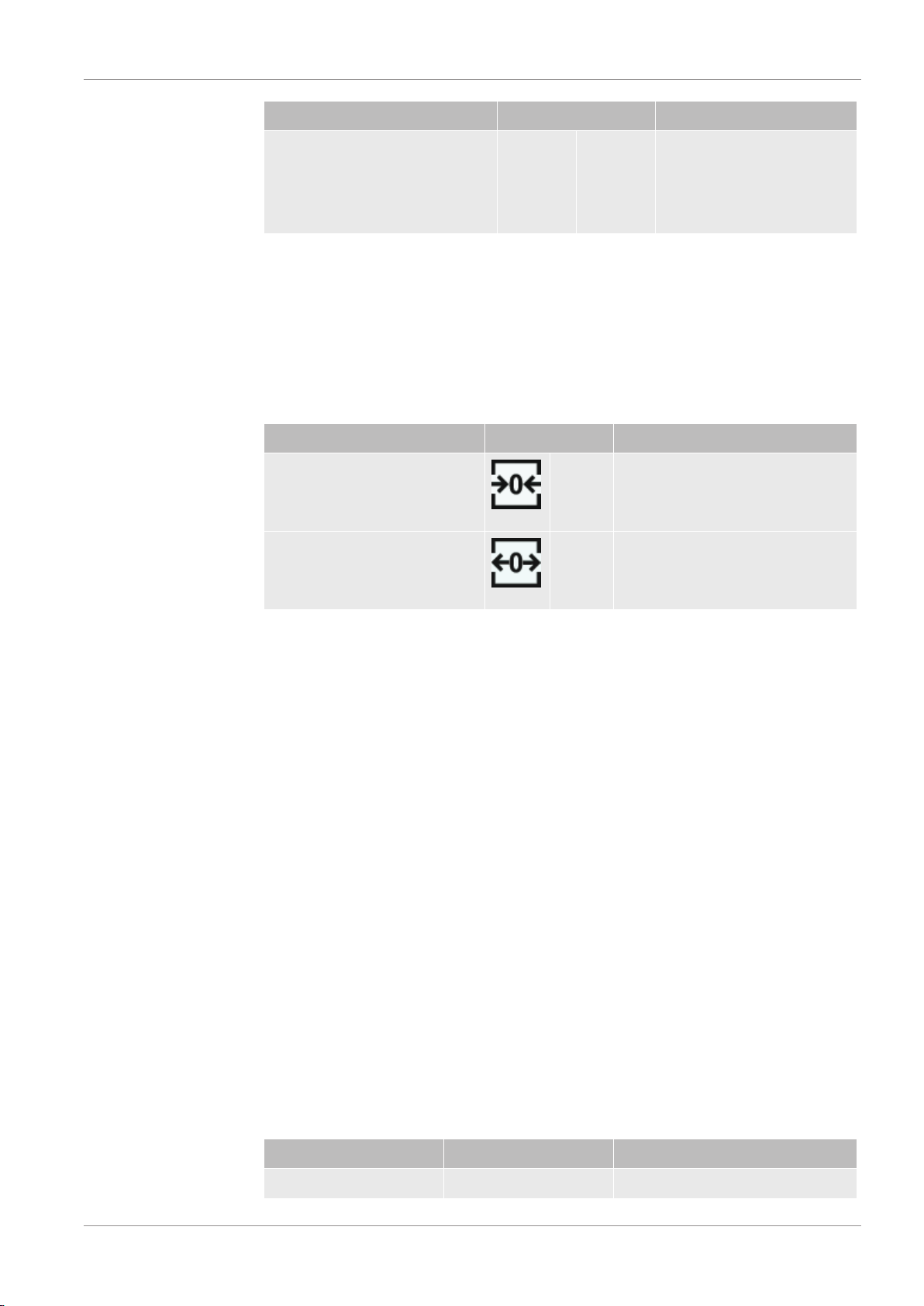
Function Touchscreen Control panel
Background suppression ON ZERO button
Background suppression OFF Press the ZERO button again and
keep it pressed for approx. 2 sec-
onds.
The actual measured leak rate is considered to be a background signal. Depending on
the selected variant of operation mode the background signal is hidden until the dis-
play limit of the respective vacuum range is reached.
After pressing the ZERO button, background suppression is automatically adjusted to
the course of the falling leak rate signal. As a result, the detection of leaks is possible
even with slowly falling signal.
Display limits according to factory setting:
1×10
-7
mbar l/s in GROSS
1×10
-10
mbar l/s in FINE
1×10
-12
mbar l/s in ULTRA
To switch-off the function ZERO again, press the button ZERO for about 2 seconds.
The function ZERO should be activated only if the leak rate signal is stable and no
leak is measured. See also “Set and use the function ZERO [}46]“.
See also
2 Change vacuum settings [}43]
4.3.2.4 Meaning of the button LEDs
START button LED STOP button LED Meaning
Off Flashing red No connection to the control unit

4 | Description LEYBOLD
18 / 94 PHOENIX-Quadro-Operating-instructions-300700189_002_C1-(1801)
START button LED STOP button LED Meaning
Pulsing blue Pulsing blue Run-up
Off Green Standby vented (Vent valve open)
Off Blue green Standby pumped out (Vent valve
close)
Pulsing green Off Pump down
Off Flashing green Internal calibration
Flashing green Off External calibration
Green Off Measuring
Yellow (warning, faulty
measurement possible)
Off Measuring with warning not ac-
knowledged
Off Red Error
Red Red Service mode is activated
ZERO button LED
Off No measurement operation
Off ZERO blocked
Blue ZERO OFF
Flashing blue ZERO blocked by SMART-ZERO
Green ZERO ON
Red Service mode is activated
4.3.2.5 Meaning of the status LED
The status LED is located on the back of the instrument inside of the connector block
for the equipment and control signals, see also Connections for accessories and con-
trol signals [}23].
Status LED Meaning
Flashing red No communication with operating unit
Flashing blue Run-up
Blue Standby
Flashing green Evacuate (pumping)
Flashing green Calibrating
Green Measuring
Yellow Measuring with warning not acknowl-
edged
Red Error
LEYBOLD Description | 4
PHOENIX-Quadro-Operating-instructions-300700189_002_C1-(1801) 19 / 94
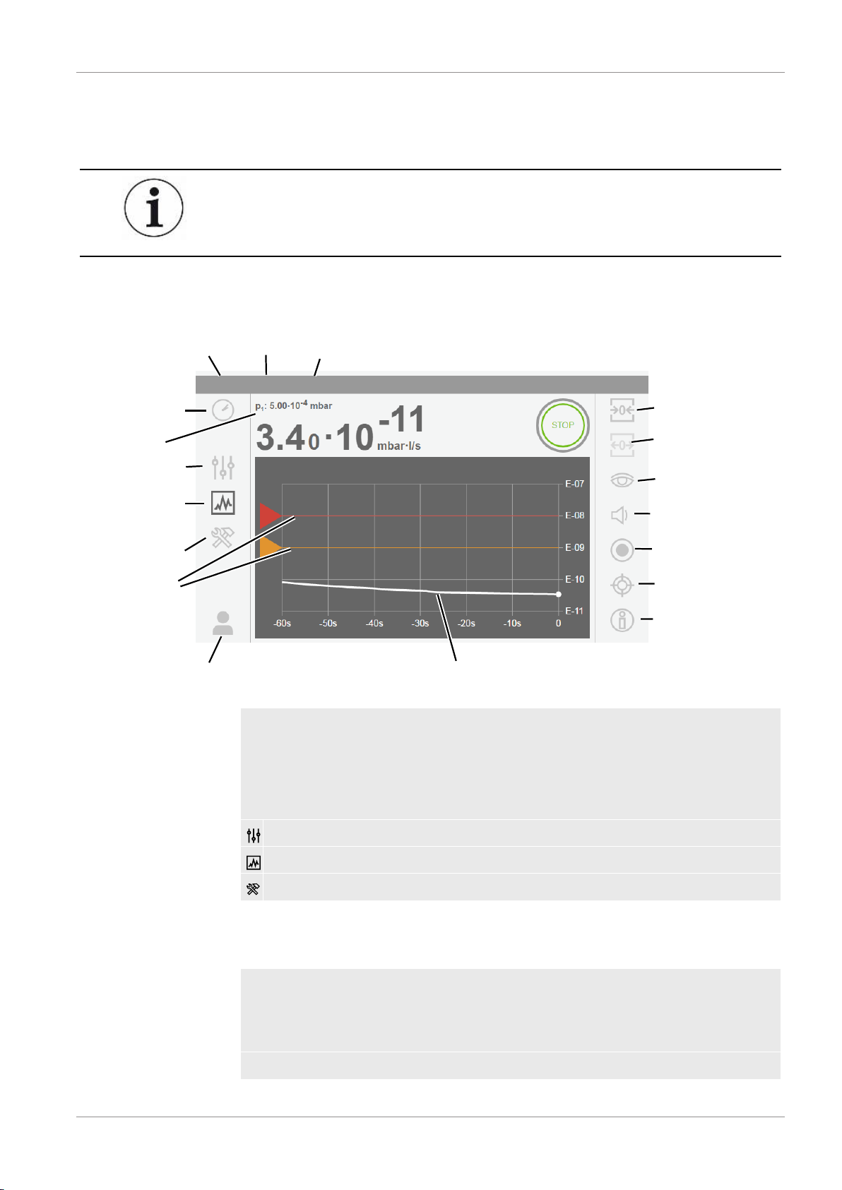
4.3.2.6 Assembly of the touchscreen
The display is a touchscreen.
The touchscreen responds to being touched lightly. To correctly select the chosen
function, avoid strong pressure.
You can always see symbols for the navigation on the display.
Additionally, you can see, depending on the context, other symbols and elements.
Operation
Information
Vacuum
access control
Settings
Diagnosis
Measuring mode
Operation mode
Gas
Time
Navigation button
Measurement value
Navigation button
Navigation button
Setpoints
Measurement value
ULTRA
Vacuum
Volume
Calibrating
ZERO ON
ZERO OFF
Measurement data recording
Switching:
Line graph
Bar graph
Helium
ULTRA
Inlet pressure
Navigation buttons
The buttons can appear in different grey tones:
• Hidden: Function inactive
• Light grey: Function can be activated
• Dark grey: Function is active
Settings
Operation
Diagnosis
Table1:
Navigation buttons
Function buttons
The buttons can appear in two different grey tones:
• Light grey: Function can be activated
• Dark grey: Function is active
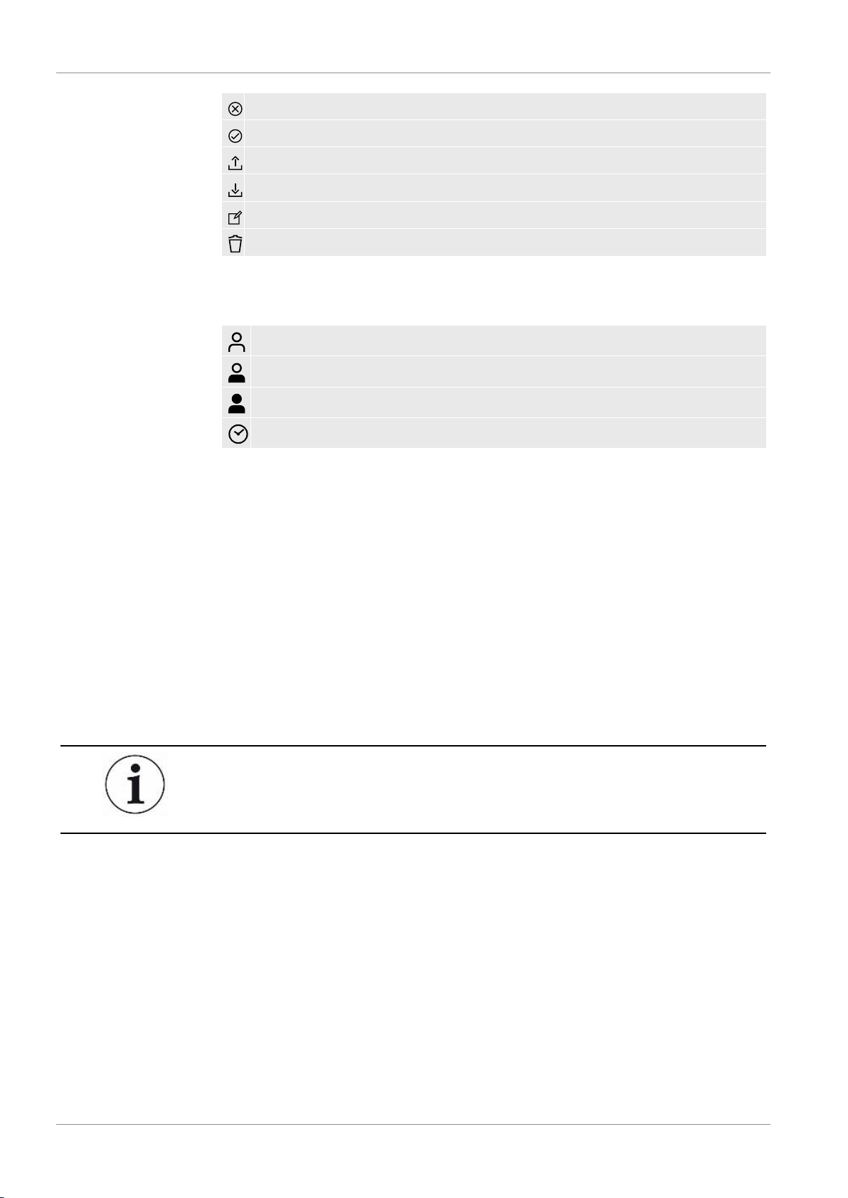
General function symbols
4 | Description LEYBOLD
20 / 94 PHOENIX-Quadro-Operating-instructions-300700189_002_C1-(1801)
Cancel ongoing function
Confirm entry or selection
Load
Save
Edit
Delete
Table2:
Function buttons
Other symbols
Authorization “User“
Authorization “Operator“
Authorization “Supervisor“
View the time or set the time
See also “Overview of Rights Groups [}33]“.
4.3.3 Vacuum connections
4.3.3.1 Inlet
The inlet is located on the upper part of the device. This is a DN 25 KF flange.
If you select the vacuum leak test mode, connect the test object or the vacuum cham-
ber onto the flange.
If you are testing applications where dust or dirt is accumulating, use the O-ring with
filter. In this case, the pump down times are extended.
Use the inlet for connecting the sniffer line SL300, too.
LEYBOLD Description | 4
PHOENIX-Quadro-Operating-instructions-300700189_002_C1-(1801) 21 / 94
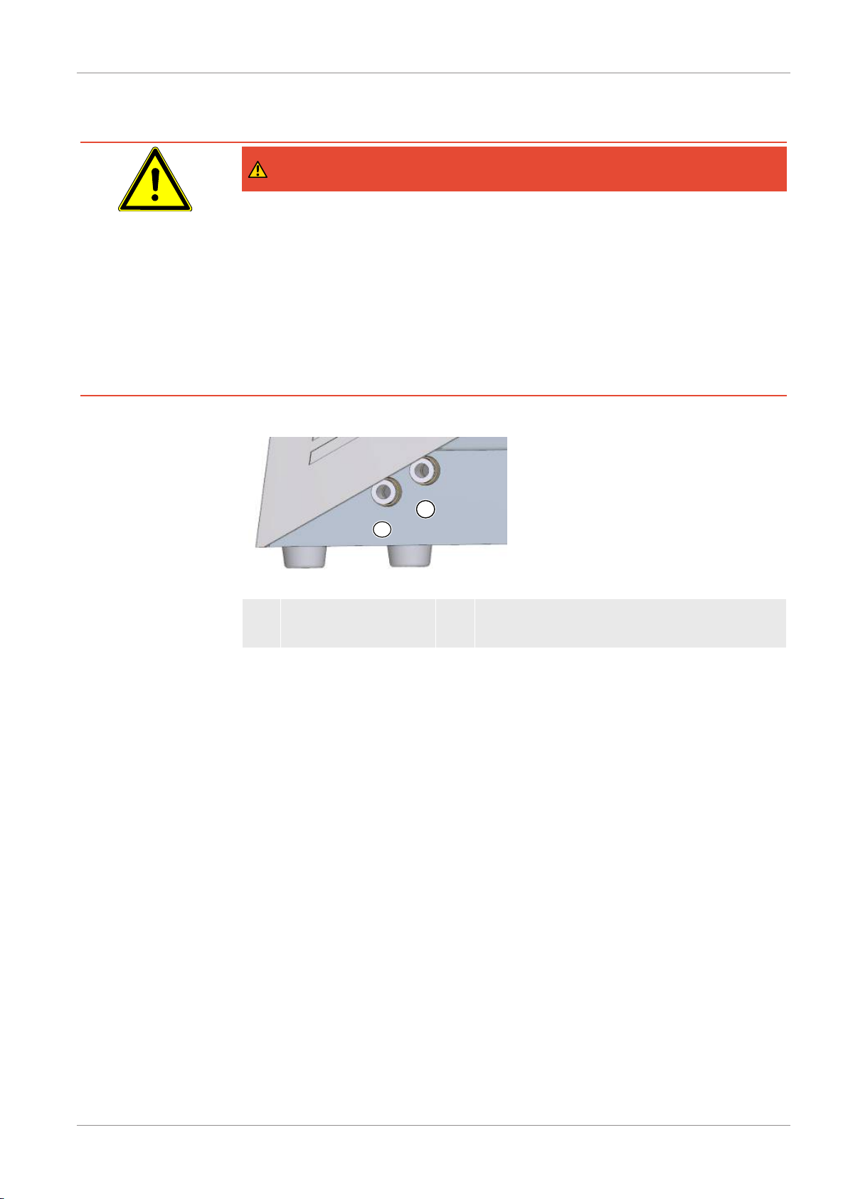
4.3.3.2 Exhaust
DANGER
Health risk due to exhaust fumes and vapors
Depending on the connected container and the gas it is holding hazardous gases can
enter the surrounding air via the exhaust of the leak detector.
If you have a device with an oil-sealed backing pump, dangerous combustion products
can arise, i.e. smoke, mist, sulfur oxide, aldehyde, and free carbon dioxide.
► Make sure you have protection measure to prevent inhaling hazardous gases.
► Connect an exhaust pipe at the exhaust, see also “Exhaust [}21]“.
User profile
1
2
EXHAUST
VENT
Fig.4:
Connections for exhaust, for venting and purging/gas ballast on the left of the device
1 EXHAUST: Exhaust 2 VENT: To vent the inlet. This connection can
be used also for purging/gas ballast.
At the left side of the device there is the an exhaust, see “Connections for accessories
and control signals [}23]“. This is a quick connection for hoses with an outside diam-
eter of 8 mm.
4.3.3.3 Connection for venting and purging/gas ballast
At the left side of the device there is the connection for venting and purging/gas bal-
last, next to “Exhaust [}21]“.
Via this connection the inlet is vented, the backing pump purged (when the backing
pump is wet: gas ballast) and the TMP vented when “power off”. This is a quick con-
nection for hoses with an outside diameter of 8 mm.
Vent
Normally, the specimens are ventilated with ambient air after completion of the test. If
necessary, the test specimens can be ventilated with a different gas (e.g., fresh air,
dry air, nitrogen, etc.) to a maximum of 1050 mbar pressure.

4 | Description LEYBOLD
22 / 94 PHOENIX-Quadro-Operating-instructions-300700189_002_C1-(1801)
Purging/gas ballast
To purge use a Helium free gas at atmospheric pressure. The surrounding air may be
contaminated with traces of Helium due to spraying or filling up large containers. In
such cases connect a gas supply line (this means Nitrogen or fresh air or similar) over
the purge gas connection. The pressure of the gas line should not be more than 1050
mbar.
LEYBOLD Description | 4
PHOENIX-Quadro-Operating-instructions-300700189_002_C1-(1801) 23 / 94
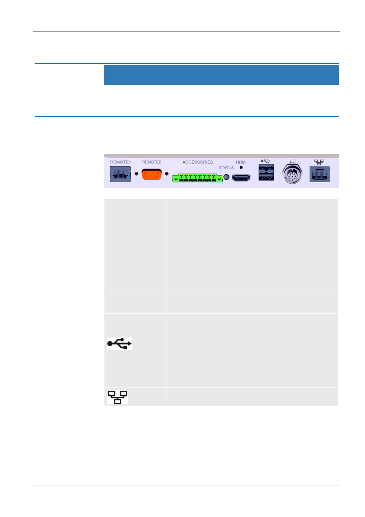
4.3.4 Connections for accessories and control signals
NOTICE
The electronics of the device can be destroyed.
► Only connect devices which are provided for the appropriate interfaces.
The connections for the external devices show a safe disconnection from the mains
and are within the range of the safety extra low voltage (SELV).
Fig.5:
Connections for accessories and control signals at the back side of the device.
REMOTE1
For connecting the remote control RC310C via cable, maxi-
mum length 28 m, or for direct connection of the radio trans-
mitter via an adapter. The remote control is not part of the
scope of delivery of the device.
REMOTE2
Enables the connection via radio transmitter for the radio
control via a special adapter.
ACCESSORIES
Electrical connection for sniffer line SL300 or partial flow sys-
tem. For partial flow system see also “Set and use external
partial flow system [}49]“.
STATUS
To display the status of the device, see also “Meaning of the
status LED [}18]“.
HDMI
For connection to the HDMI interface of a touch monitor,
maximum cable length 3 m.
2 USB connections. To transfer data and to perform updates
with an USB stick (FAT32-formatted). To connect a touch
monitor via USB cable.
LD
Connection for bus module or I/O module, maximum line
length 10 m
Network interface, maximum length 3 m
See also
2 Connection for venting and purging/gas ballast [}21]
2 Exhaust [}21]
2 Connecting the leak detector to the power supply system [}29]

4 | Description LEYBOLD
24 / 94 PHOENIX-Quadro-Operating-instructions-300700189_002_C1-(1801)
4.3.5 Markings on the device
Device cannot be scrapped with the normal domestic waste.
4.4 Technical data
Mechanical data
Device with oil-sealed backing pump, catalog numbers:
250000V02 (EU), 251000V02 (US), 251100V02 (JP)
PHOENIX Quadro
Dimensions (L×W×H) 495 mm x 318 mm x 475 mm
Weight 41 kg
Inlet flange test object DN 25 KF
Inlet flange prevacuum -
Device with dry backing pump, catalog number:
250001V02 (all countries)
PHOENIX Quadro dry
Dimensions (L×W×H) 495 mm x 318 mm x 475 mm
Weight 35 kg
Inlet flange test object DN 25 KF
Inlet flange prevacuum -
Electrical data
Device with oil-sealed backing pump, catalog numbers:
250000V02, 251000V02, 251100V02
PHOENIX Quadro
Main fuse 2 x 250 V T10 A
Max. power 640 VA
Power port for backing pump -
Supply voltage EU 220 – 240 V, 50 Hz
230 V, 60 Hz
Supply voltage US 110 -120 V, 60 Hz

LEYBOLD Description | 4
PHOENIX-Quadro-Operating-instructions-300700189_002_C1-(1801) 25 / 94
PHOENIX Quadro
Supply voltage JP 100 V, 50 / 60 Hz
Supply voltage multi-range
power unit
-
Ingress protection IP 30
Excess voltage category II
Electronic interfaces REMOTE1, REMOTE2, ACCESSORIES, HDMI,
USB, LD, Ethernet
Device with dry backing pump, catalog number:
250001V02
PHOENIX Quadro dry
Main fuse 2 x 250 V T10 A
Max. power 470 VA
Power port for backing pump -
Supply voltage EU -
Supply voltage US -
Supply voltage JP -
Supply voltage multi-range
power unit
100 - 240 V, 50 / 60 Hz
Ingress protection IP 30
Excess voltage category II
Electronic interfaces REMOTE1, REMOTE2, ACCESSORIES, HDMI,
USB, LD, Ethernet
Physical data
Catalog numbers:
250000V02, 251000V02, 251100V02, 250001V02
PHOENIX Quadro, PHOENIX Quadro dry
Minimum detectable helium leak
rate vacuum mode
5·10
-12
mbar l/s
Response time < 1 s
Maximum inlet pressure 15 mbar
Helium pumping speed ULTRA >3.1 l/s
Detectable masses
4
He, H
2
, mass 3

4 | Description LEYBOLD
26 / 94 PHOENIX-Quadro-Operating-instructions-300700189_002_C1-(1801)
PHOENIX Quadro, PHOENIX Quadro dry
Minimum detectable helium leak
rate sniffer mode
1·10
-9
mbar l/s *)
Gas flow through sniffer line
SL300
20 - 25 sccm
Measurement range 12 decades
Run-up time 110 s
Ion source 2 long lasting iridium cathodes
*) Under normal environmental conditions, the smallest detectable leak rate and leak
rate indication is after ZERO 1·10
-8
mbar l/s. In special devices, where the air helium is
removed, for example, by flooding with nitrogen, the minimum detectable leak rate can
be adjusted to 1·10
-9
mbar l/s. Please contact Leybold in this case.
Ambient conditions
Catalog numbers:
250000V02, 251000V02, 251100V02, 250001V02
PHOENIX Quadro, PHOENIX Quadro dry
Max. altitude above sea level 2000 m
Maximum relative humidity 80% at 30°C, linear decreasing to 50% at 40°C
Storage temperature - 10°C to +60°C
Operating temperature + 10°C … + 40 °C
Pollution degree 2
LEYBOLD Installation | 5
PHOENIX-Quadro-Operating-instructions-300700189_002_C1-(1801) 27 / 94
5 Installation
5.1 Setup
CAUTION
Risk of injury from lifting the heavy device
The device is heavy and can slip out of hand.
► Do not use the inlet flange to lift the device.
► Lift and transport the device only in pairs.
► To lift, grasp the handle grips on the sides of the device.
DANGER
Health risk due to exhaust fumes and vapors
Depending on the connected container and the gas it is holding hazardous gases can
enter the surrounding air via the exhaust of the leak detector.
If you have a device with an oil-sealed backing pump, dangerous combustion products
can arise, i.e. smoke, mist, sulfur oxide, aldehyde, and free carbon dioxide.
► Make sure you have protection measure to prevent inhaling hazardous gases.
► Connect an exhaust pipe at the exhaust, see also “Exhaust [}21]“.
WARNING
Danger from moisture and electricity
Moisture entering the device can lead to personal injury due to electric shocks as well
as damage to property due to short circuiting.
► Only operate the device in dry environments and only in buildings.
► Operate the device away from sources of liquid and moisture.
► Place the device where you can always reach the mains plug.
► Do not operate the device standing water and do not let even a drop of water or
other liquids on the device.
► Prevent the device from coming into contact with bases, acids and solvents.

5 | Installation LEYBOLD
28 / 94 PHOENIX-Quadro-Operating-instructions-300700189_002_C1-(1801)
NOTICE
Material damage from overheated device
The device heats up during operation and can overheat without sufficient ventilation.
► Please note the technical specifications.
► Ensure sufficient ventilation, especially on the ventilation slots on the left and right
of the device: There should be free space in the front, to the rear and sides of the
unit of at least 10 cm.
► Keep heat sources away from the device.
NOTICE
Operating system can be attacked via USB or Ethernet
The Linux operating system used in the leak detector is not updated automatically and
can therefore contain security gaps. This vulnerability may be exploited through the
Ethernet and USB interfaces of the leak detector to provide unauthorized access to
the system.
► Ensure that no unauthorized person has access to these interfaces, for example
through a USB port / Ethernet port lock.
► In order not to jeopardize the security of your company network, never connect the
leak detector directly to the public Internet. This is true for connections over WLAN
as well as over Ethernet.
► However, if you want to access the web interface of the leak detector remotely, we
recommend an encrypted Virtual Private Network (VPN) connection. However, we
cannot assume any guarantee for the security of VPN connections, which are pro-
vided by third parties.
Prevention of measurement errors due to leaks in the Helium source in the de-
vice surroundings
We recommend that you regularly check around the device to a distance of 10 m all
large Helium sources for gross leaks. Use a sniffer line to do this.
LEYBOLD Installation | 5
PHOENIX-Quadro-Operating-instructions-300700189_002_C1-(1801) 29 / 94
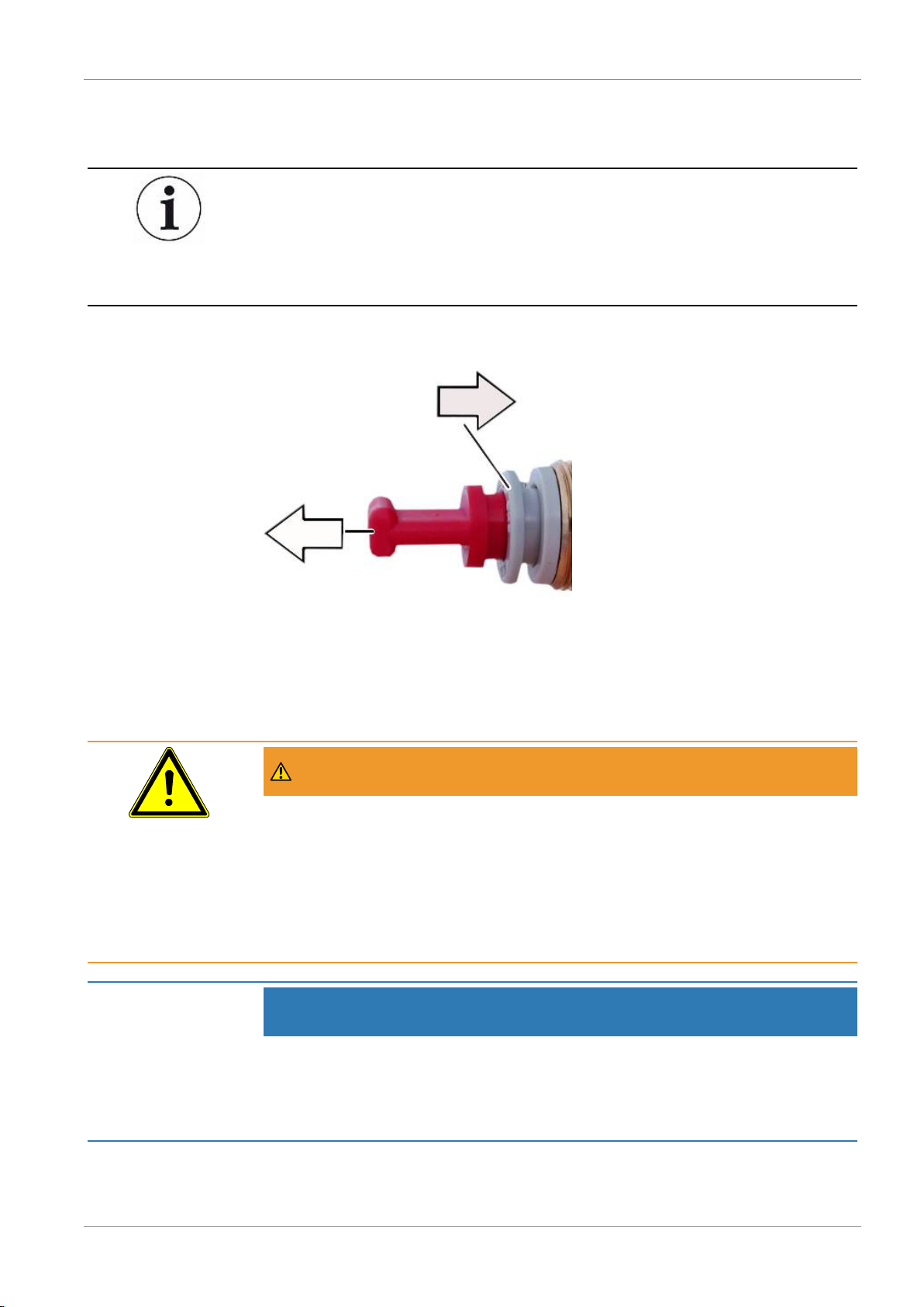
5.2 For oil-sealed backing pumps, remove the plug
Malfunction of the pump system with inserted plug in the exhaust line
On devices with oil-sealed backing pump, the exhaust is protected by a plug against
leaking oil.
► For devices with oil-sealed backing pump, remove the plug before switching it on.
►
To remove the plug press the release ring in the direction of the device so that the
locking device releases. Pull the plug out while release ring is pressed.
5.3 Connecting the leak detector to the power
supply system
WARNING
Danger from electric shock
Improperly earthed or protected products may be dangerous to life in case of a fault.
The use of the device is not permitted without a connected protective conductor.
► Only use the included 3-wire power cable.
► Make sure that the mains plug is always accessible.
NOTICE
Damage through wrong power supply
► Only connect the device to the power supply when the tension shown on the type
plate corresponds to the one of your power supply connection.
Loading...