

Page 1
GA 01.203/10.02
TRIVA C®B
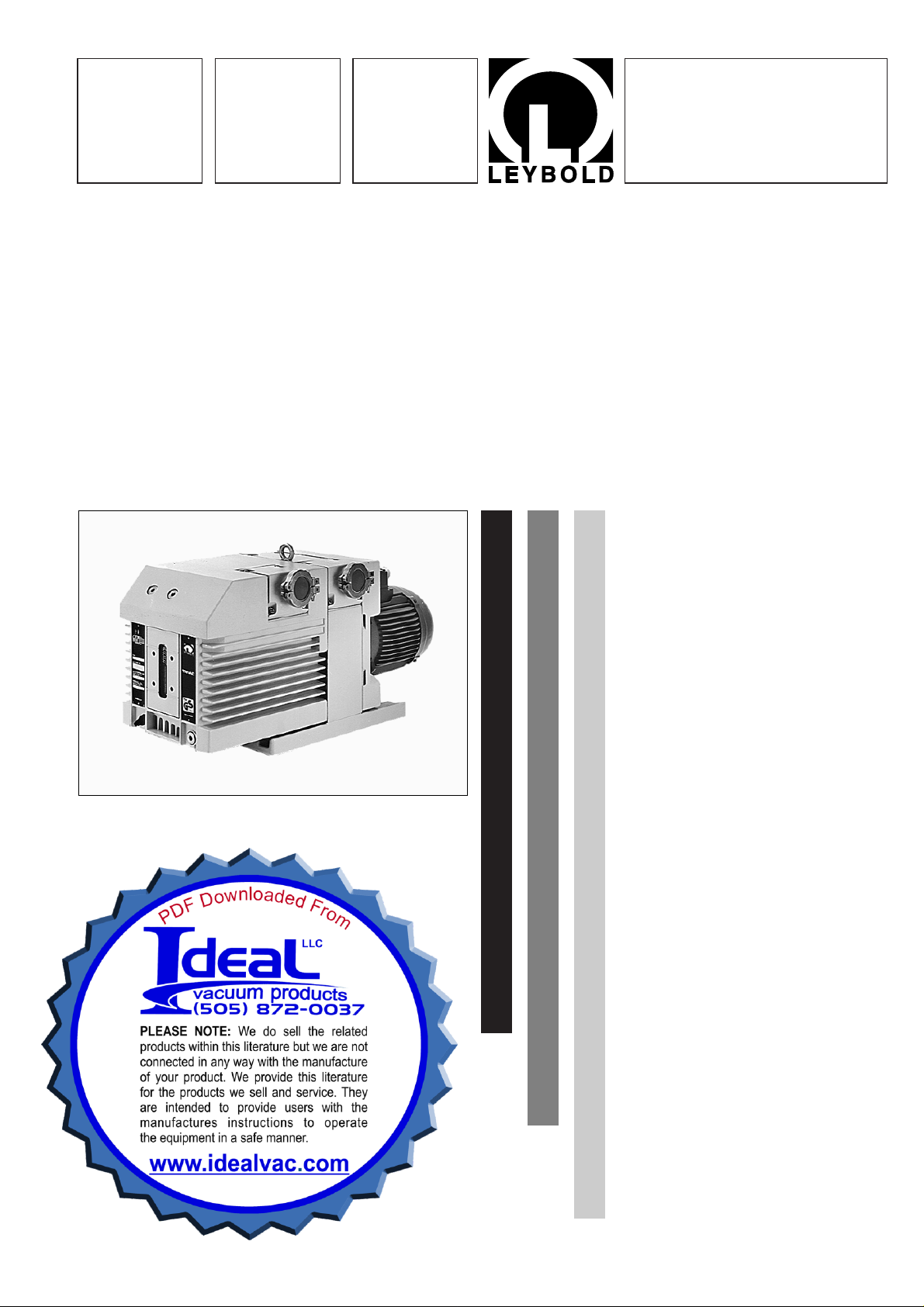
Rotary Vane Vacuum Pump
D 40 B, D 65 B
Cat. No.
112 86/96
113 45/46/47/55/56/57
Operating Instructions
Vacuum Solutions
Application Support
Service
LEYBOLD VACUUM
Page 2

GA 01.203/10.02 - 07/02
Contents
2
Contents
Page
IMPORTANT SAFETY CONSIDERATIONS . .4
1 Description . . . . . . . . . . . . . . . . . . . . . . . . . . . 6
1.1 Function . . . . . . . . . . . . . . . . . . . . . . . . . . . . . . 7
1.2 Supplied equipment . . . . . . . . . . . . . . . . . . . . . . 9
1.3 Accessories . . . . . . . . . . . . . . . . . . . . . . . . . . . . 9
1.4 Spare parts . . . . . . . . . . . . . . . . . . . . . . . . . . . . 9
1.5 Transportation . . . . . . . . . . . . . . . . . . . . . . . . . . 9
1.6 Technical data . . . . . . . . . . . . . . . . . . . . . . . . . 10
2 Operation . . . . . . . . . . . . . . . . . . . . . . . . . . . . 12
2.1 Installation . . . . . . . . . . . . . . . . . . . . . . . . . . . . 12
2.2 Connection to the system . . . . . . . . . . . . . . . . 13
2.3 Electrical connection . . . . . . . . . . . . . . . . . . . . 14
2.4 Start-up . . . . . . . . . . . . . . . . . . . . . . . . . . . . . . 15
2.5 Operation . . . . . . . . . . . . . . . . . . . . . . . . . . . . 16
2.6 Switching off/shutdown . . . . . . . . . . . . . . . . . . 17
3 Maintenance . . . . . . . . . . . . . . . . . . . . . . . . . 18
3.1 Checking the oil level . . . . . . . . . . . . . . . . . . . . 18
3.2 Oil change . . . . . . . . . . . . . . . . . . . . . . . . . . . 19
3.3 Cleaning the dirt trap . . . . . . . . . . . . . . . . . . . . 19
3.4 Removing and fitting the internal demister . . . . 20
3.5 Disassembly and reassembly of the
electric motor . . . . . . . . . . . . . . . . . . . . . . . . . 21
3.6 Replacing the shaft seal . . . . . . . . . . . . . . . . . 22
3.7 Removing and remounting the pump module . . 23
3.8 Leybold service . . . . . . . . . . . . . . . . . . . . . . . . 25
3.9 Storing the pump . . . . . . . . . . . . . . . . . . . . . . . 25
3.10 Maintenance plan . . . . . . . . . . . . . . . . . . . . . . 26
4 Troubleshooting . . . . . . . . . . . . . . . . . . . . . . . 27
EEC Declaration of Conformity . . . . . . . . .28
EEC Manufacturer’s Declaration . . . . . . . .29
We reserve the right to modify the design and the
specified data.The illustrations are not binding.
Page 3
Note
We strongly recommend that you read
these Operating Instructions with care so as
to ensure optimum operation of the pump
right from the start.
Indicates procedures that must be strictly
observed to prevent hazards to persons.
Indicates procedures that must strictly be
observed to prevent damage to, or
destruction of the pump.
Figures
The references to diagrams, e.g. (1/2) consist of the Fig.
No.and the Item No. in that order.
Leybold-Service
If a pump is returned to LEYBOLD, indicate whether the
pump is free of substances damaging to health or
whether it is contaminated.
If it is contaminated also indicate the nature of the
hazard. LEYBOLD must return any pumps without a
„Declaration of Contamination“ to the sender’s address.
Disposal of Waste Oil
Owners of waste oil are entirely self-responsible for
proper disposal of this waste.
Waste oil from vacuum pumps must not be mixed with
other substances or materials.
Waste oil from vacuum pumps (Leybold oils which are
based on mineral oils) which are subject to normal wear
and which are contaminated due to the influence of
oxygen in the air, high temperatures or mechanical wear
must be disposed of through the locally available waste
oil disposal system.
Waste oil from vacuum pumps which is contaminated
with other substances must be marked and stored in
such a way that the type of contamination is apparent.
This waste must be disposed of as special waste.
European, national and regional regulations concerning
waste disposal need to be observed.Waste must only be
transported and disposed of by an approved waste
disposal vendor.
3
GA 01.203/10.02 - 07/02
Warning
Caution
Page 4
GA 01.203/10.02 - 07/02
4
IMPORTANT SAFETY CONSIDERATIONS
The Leybold TRIVAC B vacuum pump is designed for safe and efficient operation when used properly and in
accordance with this manual. It is the responsibility of the user to carefully read and strictly observe all safety
precautions described in this section and throughout the manual. This product must be operated and maintained by
trained personnel only. Consult local, state, and national agencies regarding specific requirements and regulations.
Address any further safety, operation and/or maintenance questions to your nearest Leybold Vacuum office.
Warning Failure to observe the following precautions could result in serious personal injury:
• Before beginning with any maintenance or service work on the TRIVAC B, disconnect the pump from
all power supplies.
• Do not operate the pump with any of the covers removed. Serious injury may result.
• If exhaust gases must be collected or contained, do not allow the exhaust line to become pressur ised.
• Make sure that the gas flow from the exhaust port is not blocked or restricted in any way.
• The standard version of the TRIVAC B is not suited for operation in explosion hazard areas.Contact us
before planning to use the pump under such circumstances.
• Before starting up for the first time, the motor circuit (3 phase) must be equipped with a suitable
protective motor switch. Please take note of the information in these Operating Instructions or on the
electric motor (wiring diagram).
• The TRIVAC B is not suited for pumping of:
- combustible and explosive gases or vapours
- radioactive and toxic substances
- pyrophorous substances.
• Avoid exposing any par t of the human body to the vacuum.
• Never operate the TRIVAC B without a connected intake line or blank flange.
• The location at which the TRIVAC B (including its accessories) is operated should be such that angles
over 10° from the vertical are avoided.
• The location of the TRIVAC B should be such that all controls are easily accessible.
• Under certain ambient conditions the TRIVAC B may attain a temperature of over 80 °C
(176 °F).There then exists the danger of receiving burns.
Note the symbols on the pump pointing to the hazards, and in the case of a hot pump wear the required
protective clothing.
• Before pumping oxygen (or other highly reactive gases) at concentrations exceeding the concentration
in the atmosphere (> 21 % for oxygen) it will be necessary to use a special pump. Such a pump will
have to be modified and de-greased, and an inert special lubricant (like PFPE) must be used.
• Before operating the TRIVAC B with atmospheric gas ballast (optional) check first compatibility with the
pumped media so as to avoid hazardous conditions during operation right from the start.
• Before commissioning the TRIVAC B, make sure that the media which are to be pumped are compatible
with each other so as to avoid hazardous situations.
All relevant safety standards and regulations must be obser ved.
• It is recommended to always operate the TRIVAC B with a suitable exhaust line which is properly
connected. It must slope down and away from the pump.
• When moving the TRIVAC B always use the allowed means.
A lifting eye is provided as standard on the pump.
Page 5

GA 01.203/10.02 - 07/02
5
Failure to observe the following precautions could result in damage to the pump:
• Do not allow the ingestion of small objects (screws, nuts, washers, pieces of wire, etc.)
through the inlet port. Always use the screen which is supplied with every pump.
• Do not use the pump for applications that produce abrasive or adhesive powders or
condensable vapours that can leave adhesive or high viscosity deposits. Please contact Leybold Sales
or Service to select a suitable separator. Also pease contact Leybold Sales or Service when planning
to pump vapours other than water vapour.
• This pump is suited for pumping water vapour within the specified water vapour tolerance limits.
• Avoid vapours that can condense into liquids upon compression inside the pump, if these substances
exceed the vapour tolerance of the pump (> 25 mbar for water vapour).
• Before pumping vapours, the TRIVAC B should have attained its operating temperature, and the gas
ballast should be set to position I (position 0 = closed, position I = max. water vapour tolerance, 25
mbar).
The pump will have attained its operating temperature about 30 min utes after starting the pump.During
this time the pump should be separated from the process, by a valve in the intake line, for example.
• In the case of wet processes we recommend the installation of liquid separators upstream and
downstream of the pump as well as the use of the gas ballast.
• The exhaust line should be laid so that it slopes down and away from the pump so as to prevent
condensate from backstreaming into the pump. For this preferably use the flange on the side of the
motor.
• The entry of par ticles and fluids must be avoided under all circumstances.
• Reactive or aggressive substances in the pump chamber may impair the operating oil or modify it.
In addition, such substances may be incompatible with the materials of the pump (Viton, gre y cast iron,
aluminium, steel, resins, glass etc.).
• Corrosion, deposits and cracking of oil within the pump are not allowed.
This information will help the operator to obtain the best performance from the equipment:
• Normal amounts of humidity within the range of the pump’s vapour tolerance will not significantly affect
pump performance when the gas ballast is active.Preferably use the e xhaust flange located on the side
of the motor.
Caution:
In the case of custom pumps (with a Cat. No. deviating from the Cat No. stated in the
EC Declaration of Conformity) please note the information provided on a separate sheet.
Caution
Note
Page 6
GA 01.203/10.02 - 07/02
Description
6
2 31
1 Description
TRIVAC B pumps are oil-sealed rotary vane pumps.The
TRIVAC D 40 B and D 65 B are dual-stage pumps. The
number in the type designation (40 or 65) indicates the
pumping speed in m3· h-1.
TRIVAC B pumps can pump gases and vapours and
evacuate vessels or vacuum systems in the fine vacuum
range.
Those of standard design are not suitable
for pumping greater than atmospheric
concentrations of oxygen, hazardous
gases, or extremely aggressive or corrosive
media.
The drive motor of the TRIVAC B is directly flanged to the
pump at the coupling housing. The pump and motor
shafts are directly connected by a flexible coupling. The
bearing points of the pump module are force lubricated
sliding bearings. All controls as well as the oil-level glass
and the nameplate are arranged on the front. All
connections are to be found at the sides of the pump.
The oil-level glass is provided with prisms for better
observation of the oil level.
The pump module consists of assembly parts which are
pin-fitted so as to allow easy disassembly and
reassembly. The pump module can be easily removed
without special tools.
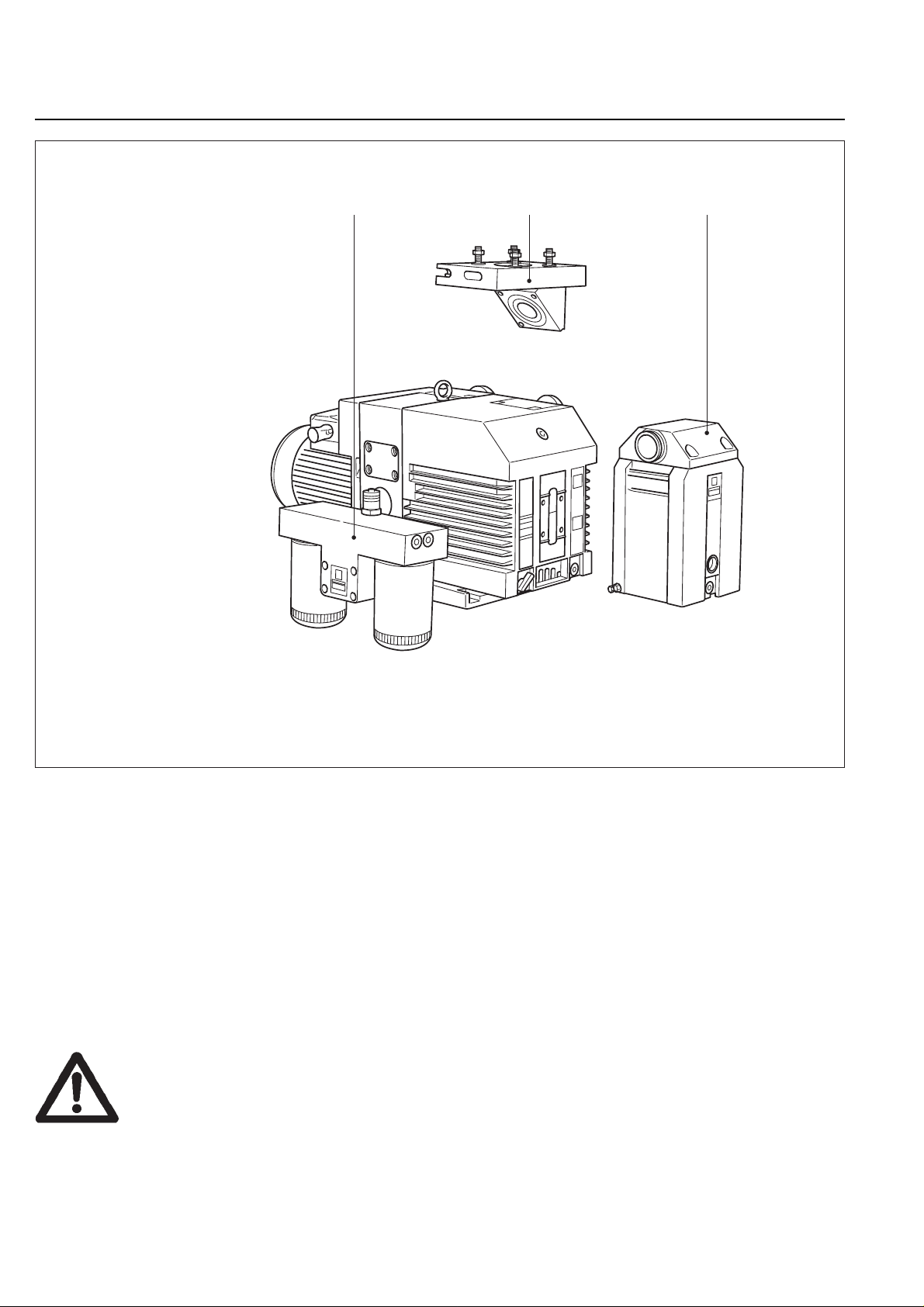
Key to Fig. 1
1 Oil filter OF 40-65
2 Roots pump adapter
3 Exhaust filter AF 40-65
Fig. 1 TRIVAC B with accessories
Warning
Page 7
GA 01.203/10.02 - 07/02
Description
7
1.1 Function
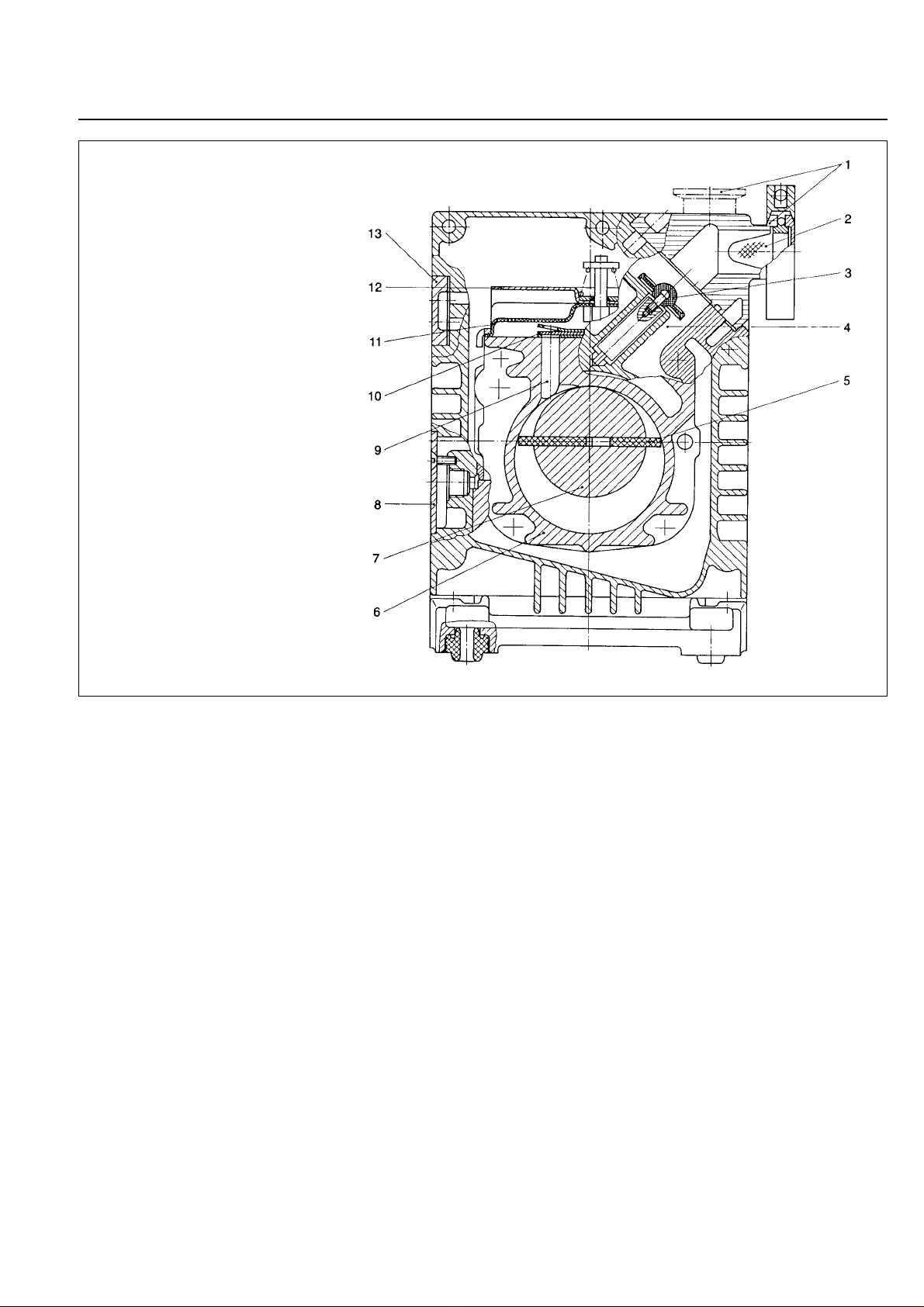
The rotor (2/7), mounted eccentrically in the pump
housing (2/6), has two radially sliding vanes (2/5) which
divide the pump chamber into several compartments.
The volume of each compartment changes periodically
with the rotation of the rotor.
As a result, gas is sucked in at the intake port (2/1).The
gas passes through the dirt trap sieve (2/2), flows past
the open anti-suckback valve (2/3) and then enters the
pump chamber.In the pump chamber, the gas is passed
on and compressed, after the inlet aperture is closed by
the vane.
The oil injected into the pump chamber is used for
sealing and lubricating. The slap noise of the oil in the
pump which usually occurs when attaining the ultimate
pressure is prevented by admitting a very small amount
of air into the pump chamber.
The compressed gas in the pump chamber is ejected
through the exhaust valve (2/10). The oil entrained in the
gas is coarsely trapped in the internal demister (2/11);
there the oil is also freed of mechanical impurities. The
gas leaves the TRIVAC B through the exhaust por t.
During compression, a controlled amount of air – the socalled gas ballast – can be allowed to enter the pump
chamber by opening the gas ballast valve (position I).
The gas ballast stops condensation of vapours in the
pump chamber up to the limit of the water vapour
tolerance as specified in the technical data for the pump.
The gas ballast valve is opened (position I) and closed
(position 0) by turning the gas ballast knob (7/5) on the
front.
To enable the TRIVAC B to be used at intake pressures
as high as 1,000 mbar, a special lubricating system was
developed featuring force-lubrication of the sliding
bearings.
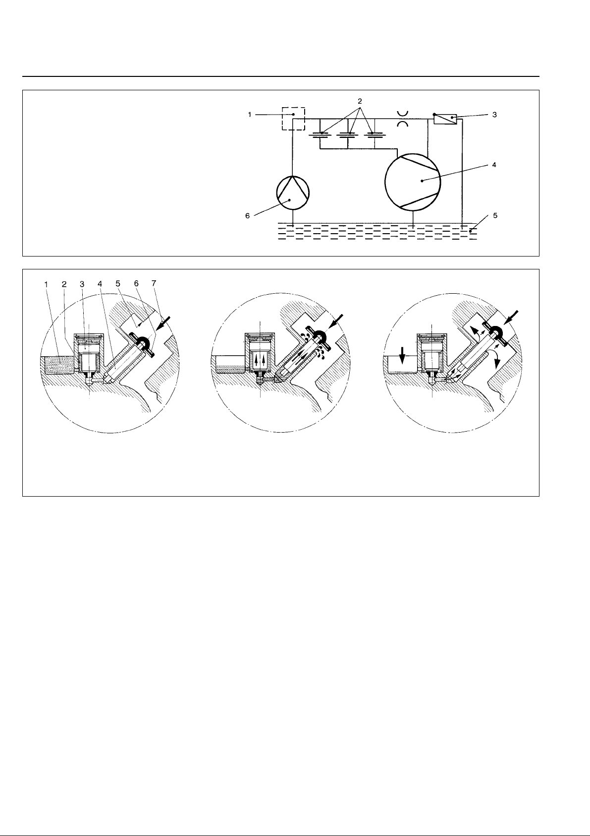
An oil pump (3/6) pumps the oil from the oil reservoir
(3/5) into a pressure-lubrication system which supplies
oil to all bearing points (3/2).From there the oil enters the
pump chamber area (3/4) of the vacuum pump.
The oil pump is fitted in the front end plate on the
coupling side of the pump module.The oil suction line is
placed low, resulting in a large usable oil reservoir.
Fig. 2 Sectional drawing of the TRIVAC B
Key to Fig. 2
1 Intake por t
2 Dirt trap
3 Anti-suckback valve
4 Intake channel
5 Vanes
6 Pump chamber
7 Rotor
8 Cover plate, connection for inert gas ballast
9 Exhaust channel
10 Exhaust valve
11 Internal demister
12 Spring buckles
13 Cover plate, connection for oil filter
Page 8
GA 01.203/10.02 - 07/02
Description
8
The oil is separated from the gas in the TRIVAC B in two
steps as described above. First, small droplets are
coalesced into large drops in the internal demister (2/11)
fitted above the exhaust valve (2/10). Then, the large
drops fall into the oil reservoir as the exhaust gas is
diverted by the inner walls of the oil case.Thus a low loss
of oil is obtained. This and the large usable oil reservoir
ensure long intervals between oil changes even at high
intake pressures.
The vacuum is maintained by the TRIVAC B through an
integrated hydropneumatic anti-suckback valve (2/3)
which is controlled via the oil pressure.
During operation of the TRIVAC B the control piston (4/3)
remains sealed against a spring (4/2) by the oil pressure.
The valve disc (4/6) of the anti-suckback valve is held at
the lower position by its own weight (valve open).
When the pump stops (because it has been switched off
or because of a failure), the oil pressure drops and the
spring (4/2) presses the control piston (4/3) up. Thus a
connection is provided between the oil case or the oil
reservoir (4/1) and the piston (4/4) of the anti-suckback
valve. Due to the pressure difference between the oil
case and the intake port the oil presses the piston (4/4)
up and the valve plate (4/6) against the valve seat (4/5).
The quantity of oil in the oil reservoir (4/1) prevents the
entry of air into the intake port (2/1) at the beginning of
this process.
After the oil has flowed out from the reservoir and when
the valve plate rests on the valve seat, air follows in,
which vents the pump chamber and forces the v alve disc
(4/6) against its seat.
This effectively prevents backstreaming of oil or oil
vapours. The anti-suckback valve (2/3) operates
independently of the operating mode of the pump, i.e.
also with gas ballast.
Fig. 3 Schematic of the lubr icating system
Fig. 4 Hydropneumatic anti-suckback valve
Key to Fig. 3
1 Accessories
2 Bearings
3 Non-return valve
4 Pump chamber of the TRIVAC
5 Oil reservoir
6 Oil pump
Key to Fig. 4
1 Oil reservoir 5 Valve seat
2 Spring 6 Valve disk
3 Control piston 7 Gas inlet
4 Anti-suckback piston
Page 9
GA 01.203/10.02 - 07/02
Description
9
1.2 Supplied Equipment
The equipment supplied with the TRIVAC B pump
includes:
Pump with motor, including initial filling of N 62 or HE200 oil,
1 centering ring,
1 centering ring with dir t trap,
2 clamping rings DN 40 KF.
For protection during shipment, the connection ports are
each blanked off by rubber diaphragms and supporting
rings.
Switches, motor protection switch, mains cable etc. are
not included.
1.3 Accessories
Cat. No. / Ref. No.
Separator AK 40-65, DN 40 KF . . . . . . . . . . . . . 188 16
Exhaust filter AF 40-65, DN 40 KF . . . . . . . . . . 189 16
Drain tap for condensate trap, exhaust filter
oil drain of the pump,
vacuum-tight . . . . . . . . . . . . . . . . . . . . . . . . . . . 190 90
oil-tight . . . . . . . . . . . . . . . . . . . . . . . . . . . . . . . 190 90
Exhaust filter with Iubricant return
AR 40-65, DN 40 KF . . . . . . . . . . . . . . . . . . . . 189 22
Exhaust filter with Iubricant return
ARS 40-65 . . . . . . . . . . . . . . . . . . . . . . . . . . . . 189 57
Dust filter . . . . . . . . . . . . . . . . . . . . . . . . . . . . . 186 15
Fine vacuum adsorption trap (with zeolite) . . . . 187 15
Adsorption trap
(with aluminium oxide) . . . . . . . . . . . . . . . . . . . 854 16
Oil filter OF 40-65 . . . . . . . . . . . . . . . . . . . . . . . 101 92
Chemical filter CF 40-65 . . . . . . . . . . . . . . . . . . 101 97
Chemical filter with safety cut-off valve
CFS 40-65 . . . . . . . . . . . . . . . . . . . . . . . . . . . . 101 77
Adapter for RUVAC 151/251 Roots pumps . . . . 168 30
Adapter for gas ballast port
M 16 x 1.5 – DN 16 KF . . . . . . . . . . . . . . . . . . .168 40
M 16 x 1.5 – 3/8inch NPT . . . . . . . . . . . . .99 175 011*)
Oil N 62 1l 177 01
(order from 5l 177 02
LH Cologne, Germany) 20 l 177 03
Oil HE-200 1 qt 98 198 006
(order from 12 qt case 98 198 049
LHVP, Export Pa., 1 gal 98 198 007
USA) 5 gal 98 198 008
The oil grades N 62 and HE-200 are interchangeable.
*) order from LHVP, Export Pa. USA
1.4 Spare par ts
Set of gaskets . . . . . . . . . . . . . . . . . . . . . . . . . 197 22
Pump module, complete D 40 B . . . . . . 200 10 933
D 65 B . . . . . . 200 10 944
Module-gasket . . . . . . . . . . . . . . . . . . . . . 200 10 744*)
Oil case gasket . . . . . . . . . . . . . . . . . . . . 200 10 741*)
Internal demister . . . . . . . . . . . . . . . . . . 390 26 014*)
*) included in gasket set
1.5 Transpor tation
• Pumps which are filled with operating
agents must only be moved while
standing upright. Otherwise oil may
escape. Avoid any other orientations
during transport.
• Check the pump for the presence of any
oil leaks, since there exists the danger
that someone may slip on spilt oil.
• When lifting the pump you must make
use of the crane eyes provided on the
pump for this purpose; also use the
recommended type of lifting device.
Caution
Warning
Page 10
GA 01.203/10.02 - 07/02
Description
10
1.6 Technical data
D 65 B
D 40 B
Druck
mbar
Saugvermögen
-1
m
h
3
-1
.
10
0
10
1
10
2
-5
10-410-310
10
-2
10
-1
10
0
10
1
10
3
10
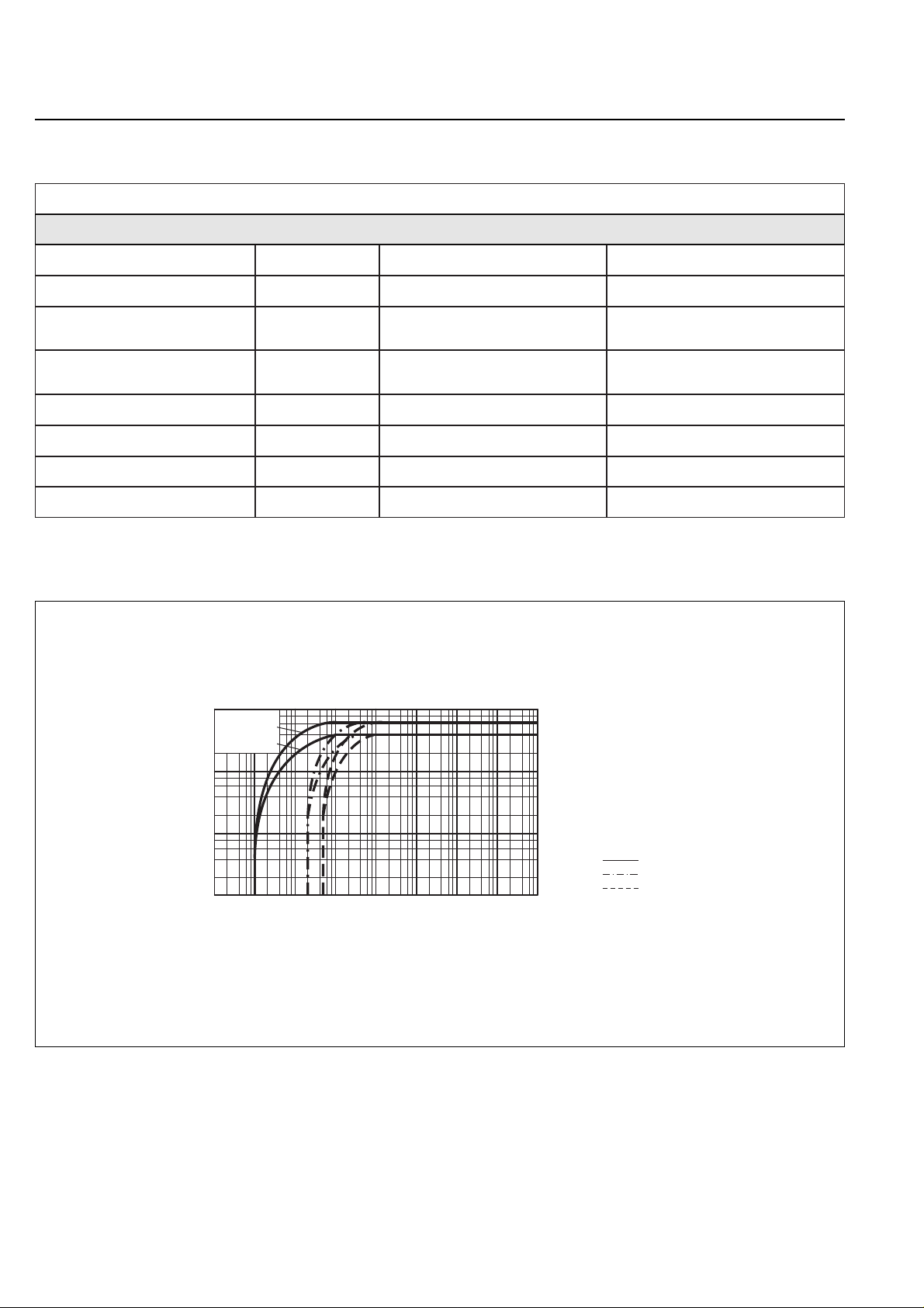
Ultimate partial pressure without gas ballast
Ultimate total pressure without gas ballast
Ultimate total pressure with gas ballast
Fig. 5 Pumping speed characteristics of the TRIVAC D 40 B and TRIVAC D 65 B, 50 Hz operation, SI units
m3· h
-1
m3· h
-1
mbar
mbar
mbar
DN
l
IP
46
40
< 1 · 10
-4
< 5 · 10
-3
40
40 KF
1,7/2,6
54
50 Hz operation, SI units
75
65
< 1 · 10
-4
< 5 · 10
-3
40
40 KF
2,0/3,3
54
Nominal pumping speed*
Pumping speed*
Ultimate partial pressure
without gas ballast*
Ultimate total pressure
with gas ballast*
Water vapour tolerance*
Connection ports
Oil filling min./max.
Type of protection
* as per DIN 28 400 and following numbers
D 40 B D 65 B
Page 11
GA 01.203/10.02 - 07/02
Description
11
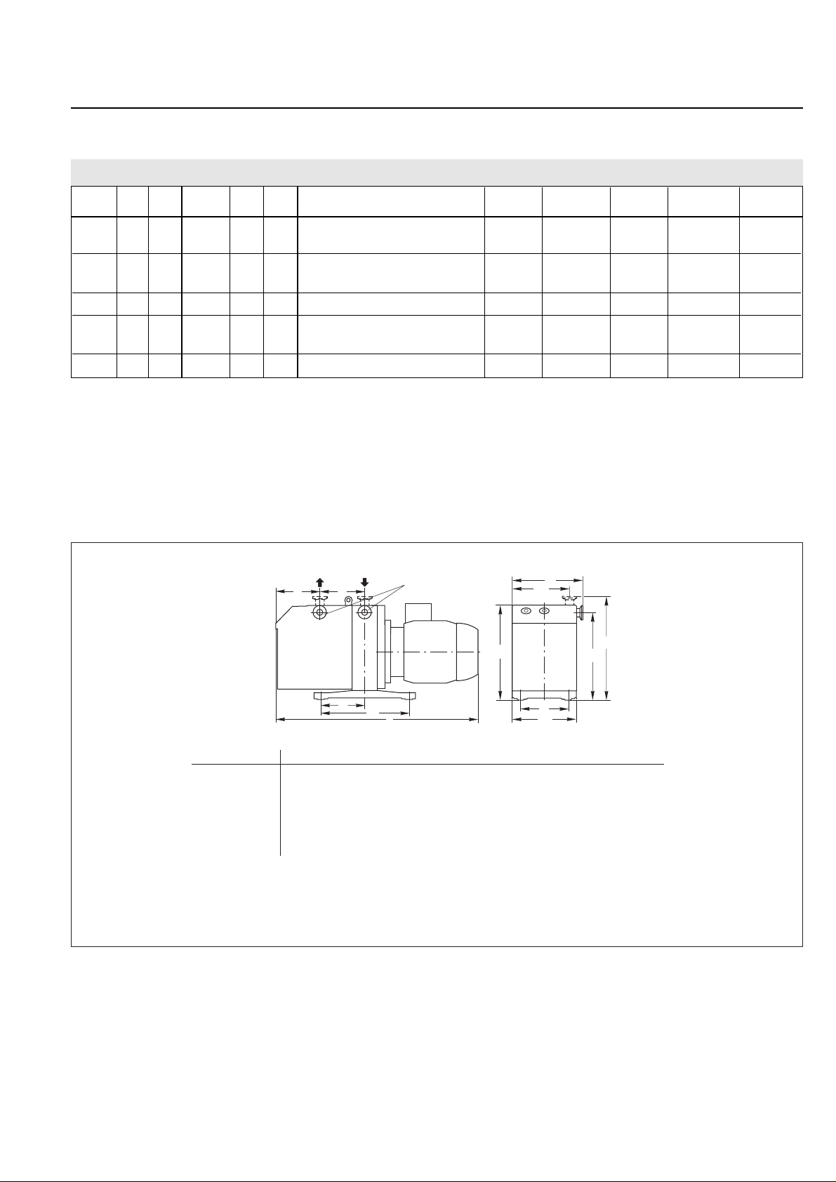
Fig. 6 Dimensional drawing for the TRIVAC rotary vane pumps (Dimensions a, l, b to b2and h1are approximate)
dimensions in mm
h
2
b
1
h
o
l
m
n
DN
c
a
b
2
b
h
1
Type DN a b b1b2chh1h
2
l* m n o
D 40 B (Part No. 112 86) 40 KF mm 135 264 234 206 166 355 336 308 670 382 191 190
in. 5.31 10.4 9.21 8.11 6.54 14 13.2 12.1 26.4 15 7.52 7.48
D 40 B (Part No. 113 45) mm (in.) 135 (5.31) 712 (28)
D 40 B (Part No. 113 47) mm (in.) 135 (5.31) 670 (26.4)
D 65 B (Part No. 112 96) mm (in.) 213 (8.39) 750 (29.5)
D 65 B (Part No. 113 55) mm (in.) 213 (8.39) 790 (31.1)
D 65 B (Part No. 113 57) mm (in.) 213 (8.39) 750 (29.5)
* Depending on the motor
USA pumps max. length
D 40 B 760 mm (30“)
D 65 B 840 mm (33.1“)
D 40 B D 65 B
1.6.1 Motor related data
1)
Motor with UL cable NEMA 5-158 and 2.5 m long cable
Cat.-No. l G Cat.-No. l G Motor-connection voltage, Motor Rated Speed Motor noise Order No.
(mm) (kg) (mm) (kg) frequency power current level motor
112 86 670 65 - - - 3~, 230-240/380-420 V ±5 %, 50 Hz 1500 W 6,9/4 A 1400 53 dB(A) 380 66 011
240-265/415-460 V ±5 %, 60 Hz 6,4/3,7 A 1700 57 dB(A)
---112 96 748 80 3~, 230-240/380-420 V ±5 %, 50 Hz 2200 W 9,7/5,6 A 1320 53 dB(A) 380 66 012
240-265/415-460 V ±5 %, 60 Hz 8,7/5 A 1640 57 dB(A)
113 451)712 73 113 55 790 84 3~, 230-380 V ±5 %, 50 Hz 2500 W 10,2/5,9 A 1400 56 dB(A) 200 10 411
113 471)670 69 113 57 748 80 3~, 200-346 V ±10 %, 50/60 Hz 2200 W 10,5/6 A 1380 55 dB(A) 200 10 412
9,5/5,5 A 1660 59 dB(A)
113 46 4101)50 113 56 4881)61 without motor - - - - -
Page 12
GA 01.203/10.02 - 07/02
Operation
12
2.1 Installation
The standard pump is not suited for
installation in explosion hazard areas.
When planning such an application please
contact us first.
The TRIVAC B pump can be set up on a flat, horizontal
surface. Rubber feet under the coupling housing ensure
that the pump can not slip.
If you wish firmly install the pump in place,
insert bolts or similar through the bore holes
in the rubber feet.
The rubber feet act as vibration absorbers.
They must therefore not be compressed by
screws.
When installing the TRIVAC B pump, make
sure that the connections and controls are
readily accessible.
Max. tilt for the pump (without further
attachment) with possibly fitted standard
accessories is 10ϒ from the vertical.
The site chosen should allow adequate air
circulation to cool the pump (keep front and
rear unobstructed). The ambient
temperature should not exceed +40 ϒC
(104 ϒF) and not drop below +12 ϒC (55
ϒF) (see Section 2.5.3).
The max. amount of heat given off
approximately corresponds to the rated
motor power.
2 Operation
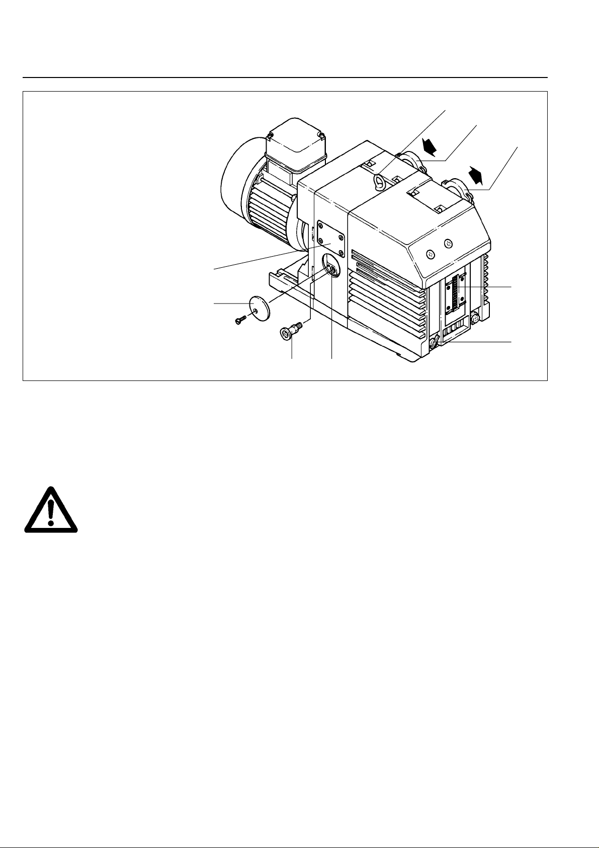
Fig. 7 Connections and controls
Key to Fig. 7
1 Eye for moving the pump
2 Intake port
3 Exhaust port
4 Oil-level glass
5 Gas ballast knob
6 Threaded connection M 16 x 1.5
(for inert gas ballast)
7 Adapter
8 Cover plate
9 Cover plate;connection for oil filter
Caution
1
2
3
4
5
67
8
9
Warning
Caution
Page 13
GA 01.203/10.02 - 07/02
Operation
13
2.2 Connection to the
System
Before connecting the TRIVAC B, remove the shipping
seals from the connection flanges (7/2) and (7/3).
Retain the shipping seals in case you need
to store the pump in the future.
The pump is shipped with intake and exhaust flanges
mounted for horizontal connection of the connecting
lines. You can easily convert the ports for vertical
connection by removing the four capscrews, rotating the
flanges as required, and reinstalling the capscrews.
Connect the intake and exhaust lines with a centering
ring and a clamping ring each. Use the center ing ring
with dirt trap for the intake port.
Connect the intake and exhaust line using anti-vibration
bellows, without placing any strain on the pump.
The intake line must be clean. Deposits in
the intake line may outgas and adversely
affect the vacuum. The connecting flanges
must be clean and undamaged.
The maximum throughput of the pump is
equivalent to the pumping speed of the
pump (see Section 1.6).
The cross-section of the intake and exhaust
lines should be at least the same size as
the connection ports of the pump. If the
intake line is too narrow, it reduces the
pumping speed. If the exhaust line is too
narrow, overpressures may occur in the
pump; this might damage the shaft seals
and cause oil leaks.
The maximum pressure in the oil case must
not exceed 1.5 bar (absolute).
When pumping vapours, it is advisable to
install condensate traps on the intake and
exhaust sides.
Install the exhaust line with a downward
slope (lower than the pump) so as to
prevent condensate from flowing back into
the pump. If this is not possible, insert a
condensate trap.
In order to reduce the emission of oil
vapours we recommend the installation of
an additional exhaust filter.
Depending on the type of application or the
kind of pumped media, the corresponding
regulations and information sheets must be
observed.
The pumps may be operated with an inert gas ballast via
a connection which is provided for this purpose. The
cover plate (7/8) can be removed to gain access to this
M 16 x 1.5 threaded port (7/6). Matching connectors are
available (see Section 1.3).
The inlet pressure for the gas ballast should be about
1000 mbar (absolute) and sufficient quantities of gas
must be available (about 1/10of the pumping speed).
Never operate the pump with a sealed
exhaust line.There is the danger of injury.
Before starting any work on the pump, the
personnel must be informed about possible
dangers first. All safety regulations must be
observed.
Caution
Warning
Caution
Caution
Page 14
GA 01.203/10.02 - 07/02
Operation
14
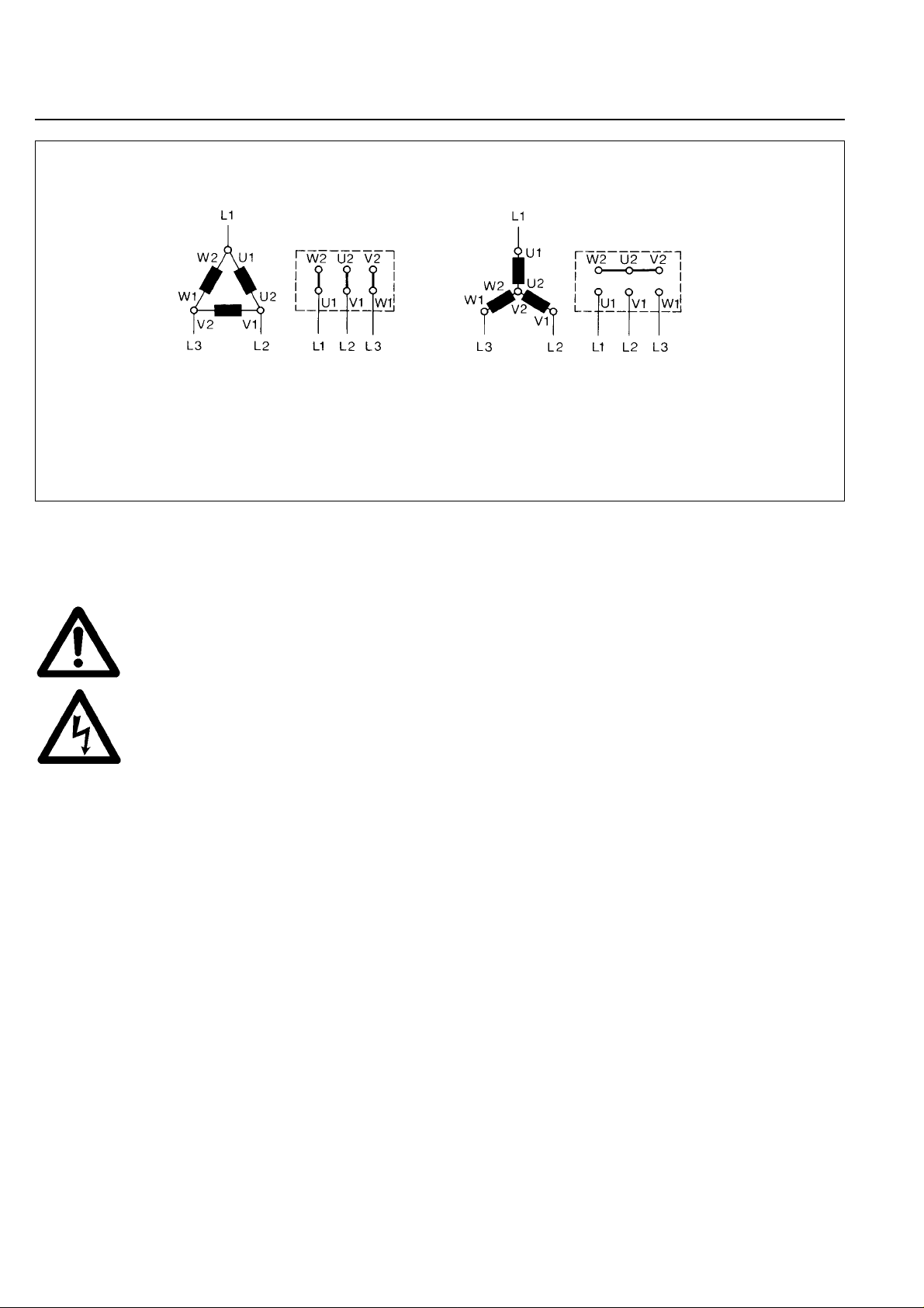
Fig. 8 Connection diagram for TRIVAC B with 50 Hz 3-phase motor
Delta connection Star connection
2.3 Electrical Connections
Before beginning with any work on the
wiring, ensure that mains supply for the
pump is off.
Electrical connections must be done by a
qualified electrician as defined by VDE
0105 in accordance with the VDE 0100
guidelines.
TRIVAC B pumps are supplied without accessories for
electrical connection. They must be connected via the
appropriate cable, and a suitable motor protection
switch. Set the switch in accordance with the rating on
the motor nameplate. Fig. 8 shows the connection for
pumps with 230/380 V, 50 Hz motors. In the case of
pumps equipped as standard with a 60 Hz motor, please
observe the diagram on or at the motor.
After connecting the motor and after every
time you alter the wiring, check the direction
of rotation. To do so, briefly switch on the
motor and check whether a suitable cover
(e. g. a blank flange) is sucked on at the
intake port. If not, interchange two phases
of the connection. Observe the direction
arrow on the coupling housing!
Warning
Caution
Page 15
GA 01.203/10.02 - 07/02
Operation
15
2.4 Star t-up
Each time before starting up check the oil
level.
For pumps with 3-phase motors, check the direction of
rotation before starting the pump for the first time and
after each change in the electrical connection (see
Section 2.3.2).
On initial start-up, after prolonged idle periods or after an
oil change, the specified ultimate pressure cannot be
attained until the oil is degassed.
This can be done by running the pump for approx. 30
min. with the intake line closed and the gas ballast valve
(7/5) open.
Before starting the pump ensure that the
pump and the fitted accessories meet the
requirements of your application and that
safe operation can be guaranteed.
Avoid exposure of any par t of the body to
the vacuum. There is the danger of injur y.
Never operate the pump with an open
intake port. Vacuum connections as well as
oil-fill and oil-drain openings must never be
opened during operation.
The safety regulations which apply to the
application in each case must be observed.
This applies to installation, operation and
during maintenance (service) as well as
waste disposal and transportation.
The standard pump is not suited for
pumping of hazardous gases or vapours.
Our technical sales department is available for further
advice in these matters.
2.4.1 Areas of Application
Before pumping oxygen (or other highly
reactive gases) at concentrations
exceeding the concentration in the
atmosphere
(> 21 % for oxygen) it will be necessary to
use a special pump.Such a pump will have
to be modified and de-greased, and an inert
special lubricant (like PFPE) must be used.
The pump is not suitable for pumping of:
– ignitable and explosiv e gases or v apours
– oxidants
– pyrophorous gases.
The pumps are not suitable for pumping of
liquids or very dusty media. Suitable
protective devices must be installed.
Our technical sales department is available for further
advice in these matters.
Caution
Warning
Warning
Caution
Page 16
GA 01.203/10.02 - 07/02
Operation
16
In cyclic operation, the TRIVAC B should not be switched
off during the intervals between the individual working
phases (power consumption is minimal when the pump
is operating at ultimate pressure), but should continue to
run with gas ballast valve open and intake port closed (if
possible via a valve).
Once all vapours have been pumped off from a process
(e.g. during dr ying), the gas ballast valve can be closed
to improve the attainable ultimate pressure.
2.5.3 Operating Temperature
Proper operation of the TRIVAC B is ensured in the
ambient temperature range between 12 °C to 40 °C
(55 °F to 104 °F).
At operating temperature, the surface
temperature of the oil case may lie between
40 °C and over 80 °C, depending on the
load.
There is the danger of receiving burns.
If – due to the ambient conditions – this temperature
range is exceeded at either end of the range, then the
operating range of the TRIVAC B can be adapted.
The Leybold sales department will be pleased to answer
any questions in this matter.
2.5 Operation
TRIVAC B pumps can pump condensable gases and
vapours, provided that the gas ballast valve (7/5) is open
and the pump has attained its operating temperature.
2.5.1 Pumping of Non-Condensable Gases
If the process contains mainly permanent gases, the
pump may be operated without gas ballast (position 0),
provided that the saturation vapour pressure at operating
temperature is not exceeded during compression.
If the composition of the gases to be pumped is not
known and if condensation in the pump cannot be ruled
out, run the pump with the gas ballast valve open in
accordance with Section 2.5.2.
2.5.2 Pumping of Condensable Gases
and V apours
With the gas ballast valve open (position I) and at
operating temperature, TRIVAC B pumps can pump pure
water vapour up to the water vapour tolerance specified
by the technical data. If the vapour pressure increases
above the permissible level, the water vapour will
condense in the oil of the pump.
When pumping vapours ensure that the gas ballast valv e
is open and that the pump has warmed up for
approximately 30 minutes with the intake line closed.
Vapour phases may only be pumped up to
the permissible limit after the pump has
attained its operating temperature.
During pumping, vapours may dissolve in
the oil. This changes the oil properties and
thus there is a risk of corrosion in the pump.
Therefore, don’t switch off the pump
immediately after completion of the
process. Instead, allow the TRIVAC B to
continue operating with the gas ballast
valve open and the intake line closed until
the oil is free of condensed vapours.
We strongly recommend operating the
pump in this mode for about 30 minutes
after completion of the process.
Caution
Warning
Page 17
GA 01.203/10.02 - 07/02
Operation
17
2.6 Switching Off/
Shutdown
Under normal circumstances, all that you need do is to
electrically switch off the TRIVAC B.No further measures
will be required.
When pumping condensable media let the
pump continue to operate with the gas
ballast valve open and the intak e line closed
before switching off (see Section 2.5.2).
When pumping aggressive or corrosive
media, let the pump continue to operate
even during long non-working intervals (e.g.
overnight) with the intake line closed and
the gas ballast valve open. This avoids
corrosion during idle periods.
If the TRIVAC B is to be shutdown for an e xtended period
after pumping aggressive or corrosive media or if the
pump has to be stored, proceed as follows:
When pumping harmful substances, take
adequate safety precautions.
Our technical sales department is available
for further advice in these matters.
Drain the oil (see Section 3.2).
Add clean oil until the oil-level is at the “min” mark (see
Section 3.2) and let the pump operate for some time.
Then drain the oil and add clean oil until the oil lev el is at
the “max.” mar k (see Section 3.2).
Seal the connection ports. Special conservation or anti-
corrosion oils aren’t necessary.
Please also take note of the information
given in Section 3.9 (storage and storage
conditions).
2.6.1 Shut-Down through Monitoring
Components
When the pump has been switched off due
to overheating sensed by the motor coil
protector, the pump must only be started
manually after the pump has cooled down
to the ambient temperature and after having
removed the cause first.
2.6.2 Failure of the Control System or the
Mains Power
In order to prevent the pump from running
up unexpectedly after a mains power
failure, the pump must be integrated in the
control system in such a way that the pump
can only be switched on again manually.
This applies equally to emergency cut-out
arrangements.
Caution
Warning
Caution
Warning
Warning
Page 18
GA 01.203/10.02 - 07/02
Maintenance
18
3 Maintenance
Disconnect the electrical connections
before disassembling the pump. Make
absolutely sure that the pump cannot be
accidentally started.
If the pump has pumped harmful
substances, ascertain the nature of hazard
and take adequate safety measures.
Observe all safety regulations.
If you send a pump to LEYBOLD for repair please
observe the information provided in Section 3.8.
When disposing of used oil, you must
observe the applicable environmental
regulations!
Due to the design concept, TRIVAC B pumps require
very little maintenance when operated under normal
conditions. The work required is described in the
sections below.
All work must be carried out by suitably
trained personnel. Maintenance or repairs
carried out incorrectly will affect the life and
performance of the pump and may cause
problems when filing warranty claims.
LEYBOLD offers practical courses on the maintenance,
repair, and testing of TRIVAC B pumps. Fur ther details
are available from LEYBOLD on request.
If the TRIVAC B is used in ambient air which
is much contaminated, make sure that the
air circulation and the gas ballast valve are
not adversely affected.
When the TRIVAC B has been pumping
corrosive media we recommend that
possibly planned maintenance work be
carried out immediately in order to prevent
corrosion of the pump while it is at
standstill.
3.1 Checking the Oil Level
During operation of the TRIVAC-B the oil level must
always remain between marks (9/2) and (9/3) on the oillevel glass. The amount of oil must be checked and
topped up as required.
Fill in oil only after the pump has been
switched off.
3.1.1 Checking the Condition of N 62 or
HE 200 Oil
The ageing process for the standard operating fluid N 62
resp.HE 200 (see Chapter 1.2.1) will depend very much
on the area of application for the pump.
a) Visual check
Normally the oil is clear and transparent. If the oil
darkens, it should be changed.
b) Chemical check
The neutralisation number of N 62 oil is determined
according to DIN 51558.If it exceeds 2, the oil should be
changed.
c) Viscosity check
If the viscosity of N 62 at 25 °C exceeds a level of
240 mPas (20% higher than the viscosity of fresh oil) an
oil change is recommended.
If gases or liquids dissolved in the oil result in a
deterioration of the ultimate pressure, the oil can be
degassed by allowing the pump to run for approx. 30
min. with the intake port closed and the gas ballast valve
open.
When wanting to check the oil, switch off the pump first
and drain out from the warm pump the required amount
of oil through the oil drain (9/4) into a beaker or similar.
Please note the safety information given in
Chapter 3.2.
Caution
Caution
Caution
Warning
Caution
Caution
Page 19
GA 01.203/10.02 - 07/02
Maintenance
19
3.2 Oil Change
Before pumping oxygen (or other highly
reactive gases) at concentrations
exceeding the concentration in the
atmosphere
(> 21 % for oxygen) it will be necessary to
use a special pump.Such a pump will have
to be modified and de-greased, and an inert
special lubricant (like PFPE) must be used.
Hazardous substances may escape from
the pump and the oil.Take adequate safety
precautions. For example wear gloves, face
protection or breathing protection.
Observe all safety regulations.
For proper operation of the pump, it is essential that the
pump has an adequate supply of the correct and clean
oil at all times.
The oil must be changed when it looks dirty or if it
appears chemically or mechanically worn out (see
Section 3.1.1).
The oil should be changed after the first 100 operating
hours and then at least every 2,000 to 3,000 operating
hours or after one year. At high intake pressures and
intake temperatures and/or when pumping contaminated
gases, the oil will have to be changed more frequently.
Further oil changes should be made before and after
long-term storage of the pump.
If the oil becomes contaminated too quickly, install a dust
filter and/or oil filter (see Section 1.3).
Contact us for more information in this matter.
Required tool:
Allen key size 8.
Only change the oil after the pump has
been switched off and while the pump is still
warm.
If there is the danger that the operating
agent may present a hazard in any way due
to decomposition of the oil, or because of
the media which have been pumped, you
must determine the kind of hazard and
ensure that all necessary safety
precautions are taken.
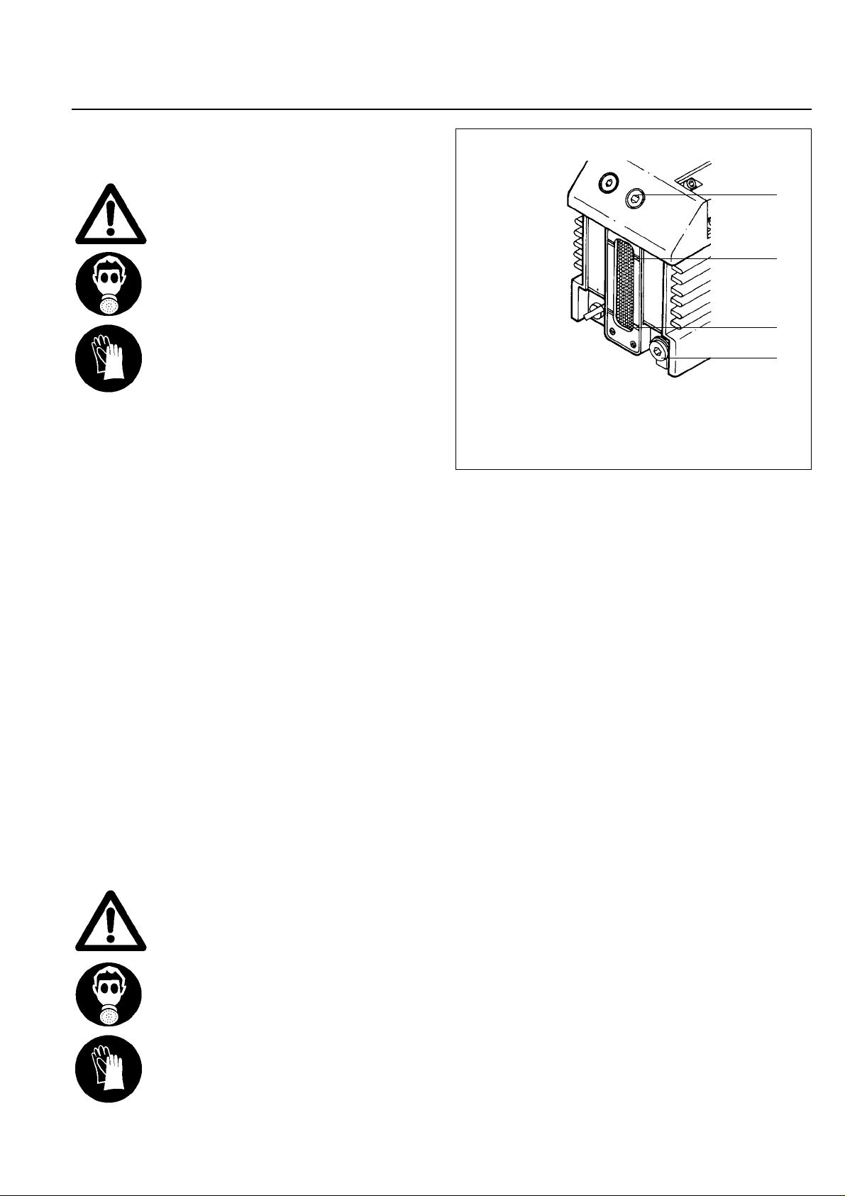
Remove the oil-drain plug (9/4) and let the used oil drain
into a suitable container. When the flow of oil slows
down, screw the oil-drain plug back in, briefly switch on
the pump (max. 10 s) and then switch it off again.
Remove the oil-drain plug once more and drain out the
remaining oil.
Screw the oil-drain plug back in (check the gasket and
reinstall a new one if necessary).
Remove the oil-fill plug (9/1) and fill in with fresh oil.
Screw the oil-fill plug (9/1) back in.
We can only guarantee that the pump
operates as specified by the technical data
if the lubricants recommended by us are
used.
3.3 Cleaning the Dir t Trap
A wire-mesh sieve is located in the intake por t of the
pump to act as a dirt trap for coarse particles. It should
be kept clean to avoid a reduction of the pumping speed.
For this purpose, remove the dirt trap (2/2) from the
intake port and rinse it in a suitable vessel with solvent.
Then thoroughly dry it with compressed air.
If the dirt trap is defective, replace it with a new one.
The cleaning intervals depend on the
application. If the pump is exposed to large
amounts of abrasive materials, a dust filter
should be fitted into the intake line.
Fig. 9 Oil change
Key to Fig. 9
1 Oil-fill plug
2 Oil-level mark “maximum”
3 Oil-level mark “minimum”
4 Oil-drain plug
Caution
Caution
1
2
3
4
Caution
Warning
Warning
Page 20
GA 01.203/10.02 - 07/02
Maintenance
20
3.4 Removing and Fitting
the Internal Demister
Required tools:
Allen keys size 6 and 8
Required spare parts:
Gasket for oil case . . . . . . . . . . . . . . . . . . 200 09 148
Internal demister: . . . . . . . . . . . . . . . . . . . . 390 26 014
The internal demister is spring-mounted in a frame.
When it is clogged, it rises periodically to reduce the
pressure difference created. The resultant noise at high
intake pressures indicates that the internal demister is
dirty.
Periodically clean or replace the internal demister; the
maintenance interval depends on the application. Use a
suitable solvent for cleaning.
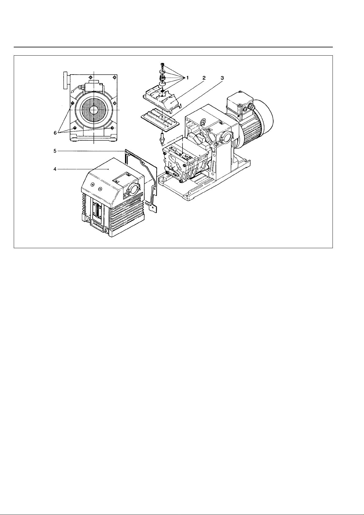
Shutdown the pump and drain the oil (see Section 3.2).
Remove the six recessed screws (10/6) on the oil case
(10/4). Don’t remove the non-recessed screws; they
hold the motor flange in place.
Pull the oil case forward off the pump.
Remove the gasket (10/5).
Unscrew screw (10/1).
Remove small washer (10/1), spring (10/1), large washer
(10/1) and O-ring (10/1)
Lift off the frame (10/2) and remove the internal demister
(10/3).
Clean all parts and check that they are in perfect
condition; if not, replace them with new parts.
Reassemble in the reverse order.
Torque for the screws (10/6) is 12 Nm.
Fig. 10 Removal and fitting of the internal demister
Key to Fig. 10
1 Screw with small washer, spr ing,
large washer and O-ring
2 Frame for demister
3 Demister
4 Oil case
5 Gasket
6 Fixing screws
Page 21
Maintenance
GA 01.203/10.02 - 07/02
21
3.5 Disassembly and
Reassembly of the
Electric Motor
Before starting any disassembly work,
always disconnect the motor from the
mains.
Reliably prevent the pump from running up.
Required tools:
Screwdriver 1.0 x 5.5 mm (for junction box), open-jaw
wrenches size 7 and size 19 (for junction bo x), Allan k eys
size 3 and size 6.
Possibly a puller for the coupling.
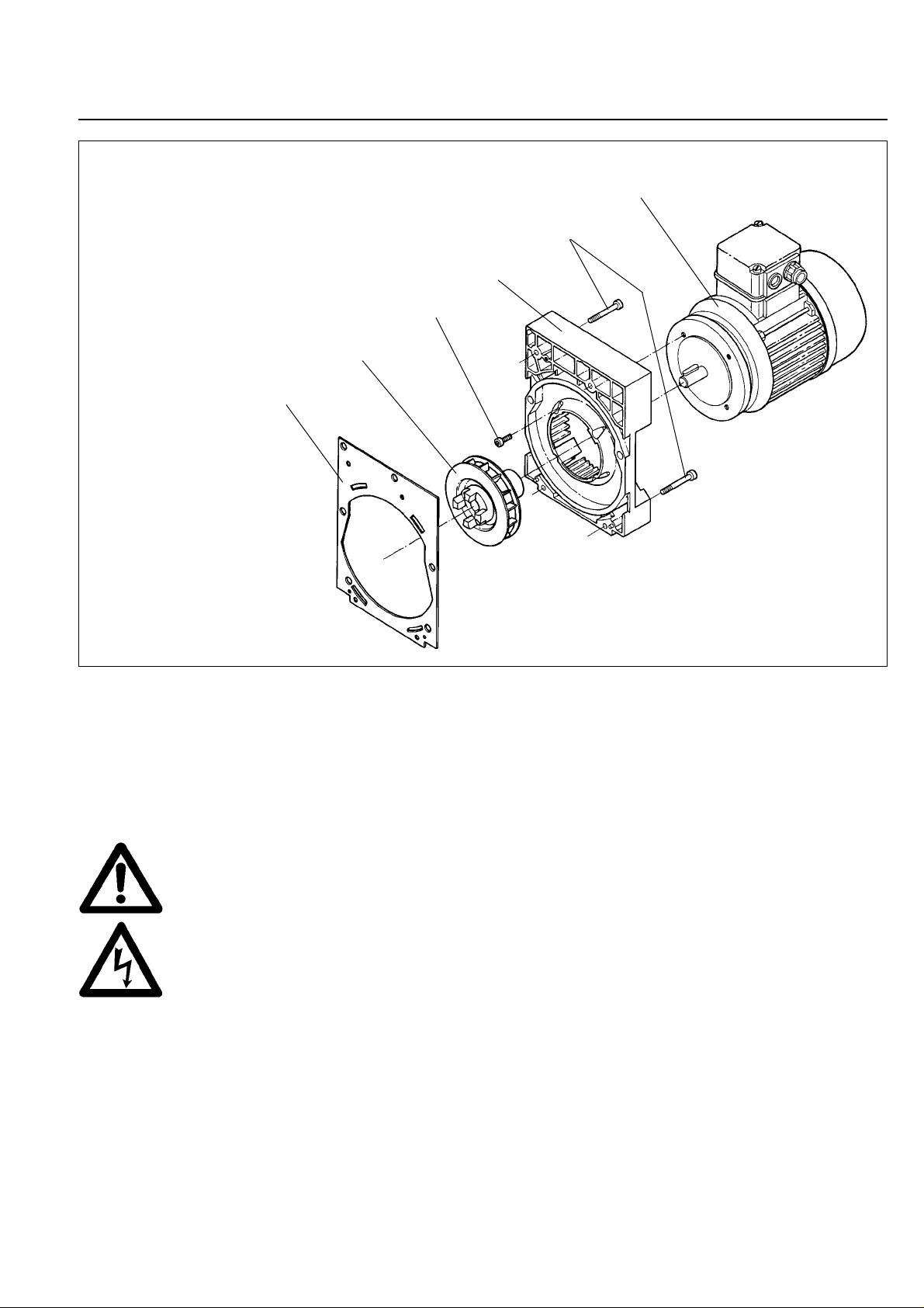
Disconnect the mains connection.
Support the motor.
Unscrew the four non-recessed hex. socket screws
(11/5).
Remove the intermediate flange (11/4) together with the
electric motor.
Remove the gasket (11/1).
Loosen the threaded pin and pull the coupling with the
blade wheel (11/2) off the motor shaft.
Unscrew the hex.socket screws (11/3).
Remove the electric motor (11/6).
Clean all parts and check that they are in perfect
condition; if not, replace them with new parts.
Reassemble in the reverse order.
In the case of 60 Hz motors (USA versions)
the coupling must not be pushed on to the
shaft right up to the stop.On the other hand
if it is not pushed on far enough the pump
module may be damaged during operation.
Push the coupling on in such a way that the
distance between the front end of the
coupling and the gasket (11/1) on the
intermediate flange amounts to 43.7 mm.
Fig. 11 Disassembly and reassembly of the electric motor
Key to Fig. 11
1 Gasket
2 Coupling with fan blades
3 Hex.socket screws
4 Intermediate flange
5 Hex.socket screws
6 Electric motor
Caution
Warning
1
2
3
4
5
6
Page 22
GA 01.203/10.02 - 07/02
Maintenance
22
3.6 Replacing the Shaft Seal
Required tools:
Allen keys size 3, 5 and 8, flat-nose pliers, plastic
hammer, shaft seal driver, possibly a puller for the
coupling.
Required spare parts:
Shaft seal . . . . . . . . . . . . . . . . . . . . . . . . . 239 53 007
Bushing . . . . . . . . . . . . . . . . . . . . . . . . . . . 231 92 034
Oil marks under the coupling housing are signs of a
damaged shaft seal.
The shaft seal can be replaced without removing or
disassembling the pump module.
Shutdown the pump.
Drain the oil (see Section 3.2).
Support the motor.
Unscrew the four non-recessed hex. socket screws
(11/5) and remove the motor (11/6).
Remove gasket (11/1).
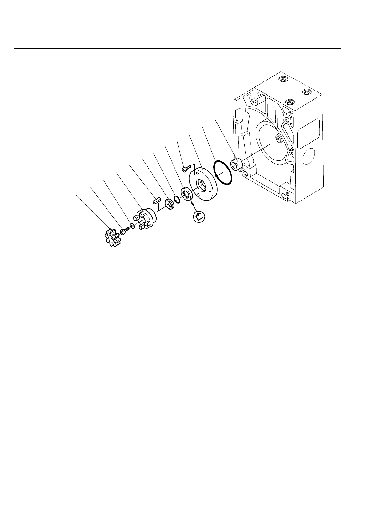
Remove coupling element (12/1).
Unscrew screw (12/2) and pull off the spring washer
(12/3).
Pull off the coupling half (12/4).
Remove key (12/5).
Pull off the compression ring (12/6) and O-ring (12/7).
Unscrew the hex. socket screws (12/9) and pull out the
centering disc (12/10).
If the centering disc does not come loose, use the forcing
thread into which screws (12/9) can be screwed in.
Remove the O-ring (12/11).
Force the shaft seal (12/8) out of the centering disk.
Pull off the bushing (12/12) from the shaft.
We recommend the use of a new shaft seal and bushing
for reassembly.
Before fitting the new shaft seal, moisten it slightly with a
little vacuum pump oil.
Using a suitable plastic or aluminium cylinder (shaft seal
driver) and a plastic hammer, force the shaft seal (12/8)
carefully and without bending it into the centering disk
(for position of shaft seal, see Fig. 12).
Fig. 12 Exchanging the shaft seal
Key to Fig. 12
1 Coupling element
2 Cylinder head screw
3 Spring washer
4 Coupling (one half)
5Key
6 Compression ring
7 O-ring
8 Shaft seal
9 Screws
10 Centering disk
11 O-ring
12 Bushing
1
2
3
4
5
6
7
8
9
10
11
12
Page 23

GA 01.203/10.02 - 07/02
Maintenance
23
If you do not have a shaft seal driv er, place the shaft seal
on the centering disk and carefully
force it in with light blows of the plastic hammer.
The shaft seal must not be bent.
Push the bushing (12/12) on to the shaft.
Insert the O-ring (12/11) into its groove.
Carefully push the centering disk (12/10) with the shaft
seal onto the shaft and up against the end plate; fasten
it with the screws (12/9).
Push the O-ring (12/7) and the compression disk (12/6)
on to the shaft.
Insert the key (12/5).
Mount the pump-half of the coupling (12/4) on the shaft.
Install the spring washer (12/3) and tighten the screw
(12/2).
Insert the coupling element (12/1) into the coupling and
mount the motor (see Section 3.5).
3.7 Removing and
Remounting the Pump
Module
Required tools:
Allen keys size 3, 5, and 8 mm, box wrench size 13,
possibly pliers, torque wrench.
Required spare parts:
Gaskets: . . . . . . . . . . . . . . . . . . . . . . . 239 73 039
. . . . . . . . . . . . . . . . . . . . . . . 200 90 148
3.7.1 Removing the Pump Module
Drain the oil and remove the oil case (see Section 3.4).
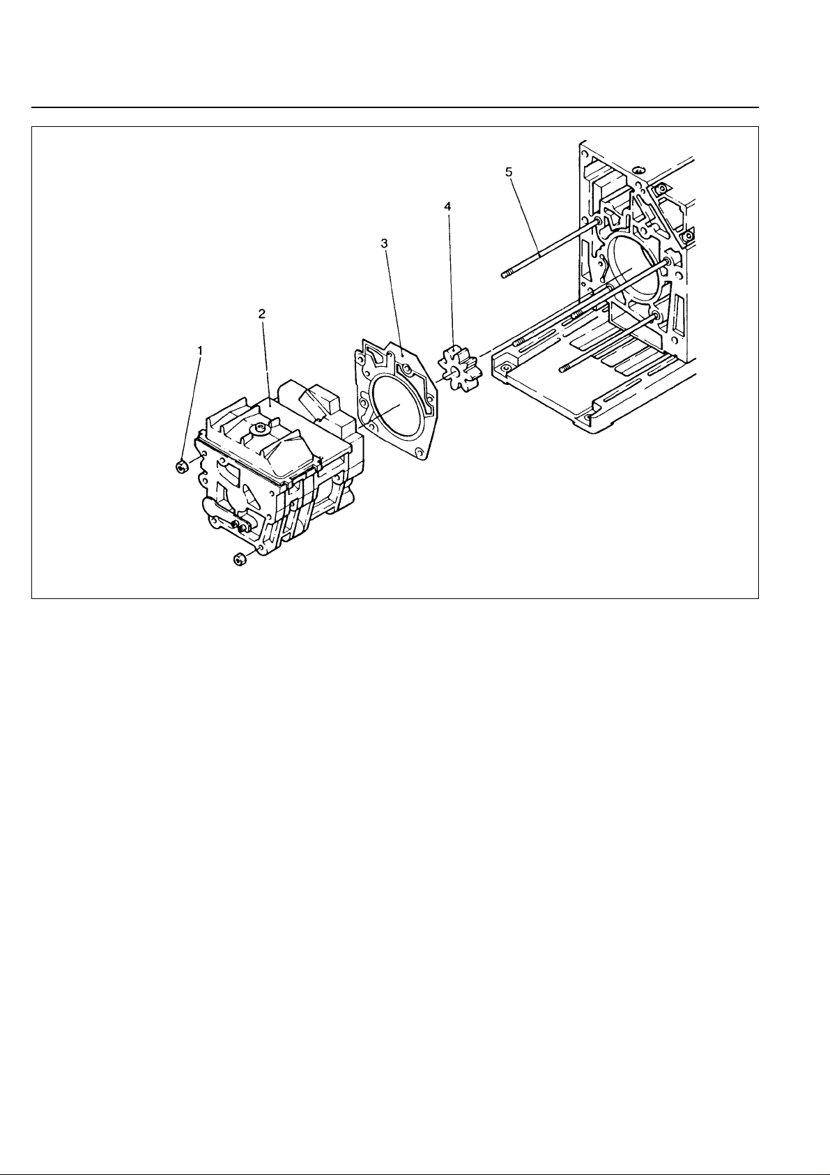
Unscrew the hex.nuts (13/1).
Pull the entire pump module (13/2) forward off the tie
rods (13/5).
When doing so, ensure that the individual
pin-fitted parts are not loosened. Further
disassembly of the pump module should
only be carried out by a trained service
engineer.
Remove the gasket (13/3).
Remove the coupling element (13/4).
After removing the protective shipping
materials, handle the new pump module
with care.
Before installing a new pump module, remo v e the f our tie
rods from the new module and insert them in the old one
for protection during shipment.
Caution
Caution
Page 24
GA 01.203/10.02 - 07/02
Maintenance
24
3.7.2 Remounting the Pump Module
When installing a new pump module, it is also advisable
to use a new gasket (13/3).
Check the coupling element (13/4) for damage; if
necessary, install a new one.
Use the tie rods supplied with the new pump module only
if the old ones are damaged. To do so, unscrew the old
tie rods with lock nuts, and screw in the new ones. With
the aid of the lock nuts, tighten the tie rods.Then remove
the lock nuts.
Push the gasket (13/3) onto the tie rods (13/5), push the
coupling element (13/4) onto one coupling half.
Push the entire pump module (new or repaired) onto the
tie rods.
Screw on the hex.nuts (13/1) and carefully cross-tighten
them (torque 17 Nm).
Mount the oil case together with the gasket (see Section
3.4).
Fill in oil.
Fig. 13 Removing and remounting the pump module
Key to Fig. 13
1 Hex.nuts
2 Pump module
4 Gasket
5 Coupling element
6 Tie rods
Page 25
GA 01.203/10.02 - 07/02
Maintenance
25
3.8 Leybold Service
If a pump is returned to Leybold, indicate whether the
pump free of substances damaging to health or whether
it is contaminated. If it is contaminated also indicate the
nature of the hazard. For this you must use a form which
has been prepared by us which we will provide upon
request.
A copy of this form is reproduced at the end of these
Operating Instructions: “Declaration of Contamination of
Vacuum Instruments and Components”.
Please attach this form to the pump or enclose it with the
pump.
This “Declaration of Contamination” is required to meet
German Law and to protect our personnel.
Leybold must return any pumps without a “Declaration of
Contamination” to the sender’s address.
The pump must be packed in such a way,
that it will not be damaged during shipping
and so that any contaminants are not
released from the package.
3.8.1 Waste Disposal of Used Pump
Materials
The corresponding environmental and safety regulations
apply. This applies equally to used filters and filter
elements (oil filter, exhaust filter and dust filter).
– In the case of hazardous substances
determine the kind of hazard first and
observe the applicable safety
regulations. If the potential hazard still
persists, the pump must be
decontaminated before starting with any
maintenance work. For professional
decontamination we recommend our
Leybold service.
– Never exchange the oil or the filters
while the pump is still warm. Let the
pump cool down to uncritical
temperatures first. You must wear
suitable protective clothing.
3.9 Storing the Pump
Before putting a pump into operation once
more it should be stored in a dry place
preferably at room temperature (20 °C).
Before the pump is shelved it must be
properly disconnected from the vacuum
system, purged with dry nitrogen and the oil
should be changed too.
The inlets and outlets of the pump must be
sealed with the shipping seals which are
provided upon delivery.
The gas ballast switch must be set to the “0”
position and if the pump is to be shelved for
a longer period of time it should be sealed
in a PE bag containing some desiccant
(silica gel).
When a pump is put into operation after it has been
shelved for over one year, standard maintenance should
be run on the pump and the oil should also be
exchanged (see Operating Instructions).We recommend
that you contact the Leybold service.
Warning
Achtung
Warning
Page 26
GA 01.203/10.02 - 07/02
Maintenance
26
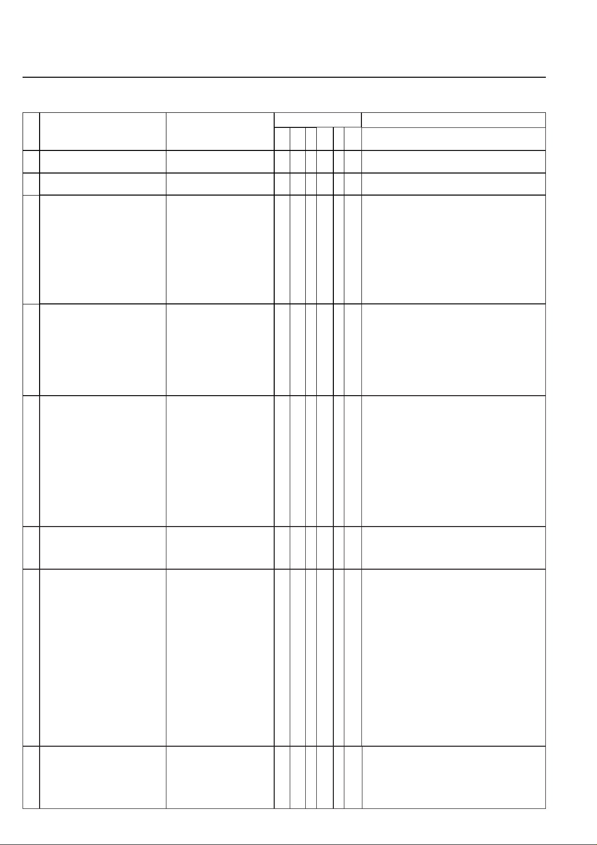
3.10 Maintenance Plan
(Recommendation)
No.
Rotary vane pumps
TRIVAC D 40 B
TRIVAC D 65 B
Measurement/test quantity
Operating/auxiliary
materials
VE VP t
6m a n-a
Remarks
1 Operate the pump for at least 0.8
hours with gas ballast.
x Condensed water is thus removed from the oil.
2 Check the oil level, change the oil
if required.
Oil: N 62 or special and
alternative oils, see Section 1.3
x x Refill:only after the pump has been switched off.
3 Check the quality of the oil,
change the oil if required.
visually
chemically
mechanically
x x
x
x
Visually: normally light and transparent, oil
change is required when discolorations increase.
Chemically: to DIN 51558 when the neutralisation
number exceeds 2; then an oil change will be
required.
Mechanically: when dynamic viscosity at 25 °C
exceeds 240 mPas; then an oil change will be
required.
Disposal of waste oil: see Chapter 3.8.1
4 Clean the dirt trap in the intake
port, change it as required.
Suitable cleaning agent and
compressed air.
x ❏ Clean dirt trap with a cleaning agent and blow it
out with compressed air under a suction hood.
❏ Replace the defective dirt trap.
Use a cleaning agent which complies with the
national / international specifications.
Observe the safety regulations when using
cleaning agents.
Interval
Refer also to the Operating Instructions
– Chapter: individual components.
5 Clean the internal demister,
change it as required.
Suitable cleaning agent. x Already clean before the maintenance interval has
elapsed when the noise level increases.
❏ Clean the internal demister using a cleaning
agent.
❏ Replace the defective internal demister.
❏ Dispose of the defective internal demister as
special waste.
Cleaning agent according to national / international
specifications.
Observe the safety regulations when using
cleaning agents.
6 Check the edges of the teeth on
the coupling element for any
damages, change the coupling
element as required.
x
7 Change the oil -
and
clean the oil level glass.
Oil: N 62 or special and
alternative oils.
Suitable cleaning agent and
compressed air.
8 Check the fan of the pump and the
motor as well as the cooling fins on
the motor for deposits and clean
as required.
Brush and industrial vacuum
cleaner.
x
x Already clean before the maintenance interval has
elapsed when the pump or the motor gets too
warm.
Caution: switch off the pump and ensure that it
can not run up inadvertently (disconnect from the
mains).
Oil change:
• First oil change after 100 operating hours.
• Pump switched off and cold.
Change the oil when the pump is cold in order to
avoid releasing absorbed gases.
❏ Clean the oil level glass with a cleaning agent
and blow it out with compressed air under a suction
hood.
Cleaning agent according to national / international
specifications.
Observe the safety regulations when using
cleaning agents.
Quantity of oil: see Operating Instructions,
Chapter 1.6.
Waste disposal of oil: see Operating Instructions,
Chapter 3.8.1.
Page 27
GA 01.203/10.02 - 07/02
Troubleshooting
27
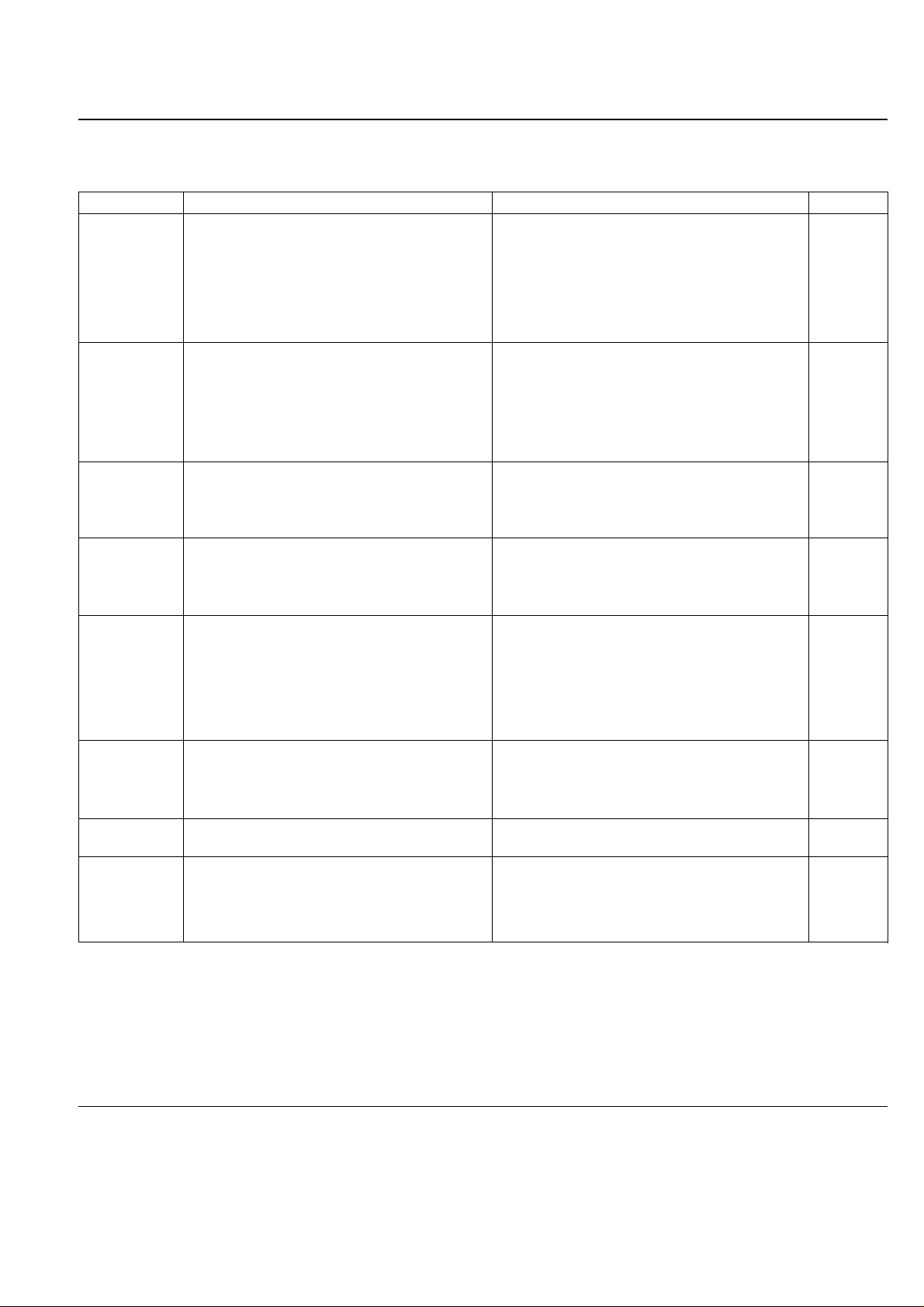
4 Troubleshooting
Fault Possible cause Remedy Repair*
Pump does not
start.
Pump does not
reach ultimate
pressure.
Wiring is malfunctioning.
Motor protection switch incorrectly set
(3-phase motors only).
Operating voltage does not match motor.
Motor is malfunctioning.
Oil temperature is below 12 ϒC.
Oil is too viscous.
Exhaust filter or exhaust line is clogged.
Pump is seized up (sign: pump is jammed).
Check and repair wiring.
Set motor protection switch properly.
Replace the motor.
Replace the motor.
Heat the pump and pump oil or use different oil.
Change the oil.
Replace the filter or clean the exhaust line.
Repair the pump.
-
2.3
3.5
3.5
2.5.3/3.2
3.2
Service
Measuring technique or gauge is unsuitable.
External leak
1)
.
Anti-suckback valve is malfunctioning.
Exhaust valve is malfunctioning.
Oil is unsuitable.
Intake line is dirty.
Pump is too small.
Use correct measuring technique and gauge.
Measure the pressure directly at pump’s intake port.
Repair the pump.
Repair the valve.
Repair the valve.
Change the oil (degas it, if necessary).
Clean vacuum lines.
Check the process data; replace the pump, if necessary.
Service
Service
Service
3.2
-
-
Pumping speed is
too low.
Dirt trap in the intake port is clogged.
Exhaust filter is clogged.
Connecting lines are too narrow or too long.
Clean the dirt trap;
Precaution: install a dust filter in intake line.
Exchange the filter element.
Use adequately wide and short connecting lines.
3.3
-
2.2
Pump gets hotter
than usually
observed.
Cooling air supply is obstructed.
Ambient temperature is too high.
Process gas is too hot.
Oil level is too low.
Oil is unsuitable.
Oil cycle is obstructed.
Exhaust filter or exhaust line is obstructed.
Exhaust valve is malfunctioning.
Pump module is worn out.
Set pump up correctly.
Set pump up correctly.
Change the process.
Add oil.
Change the oil.
Clean or repair the oil lines and channels.
Replace the exhaust filter, clean the exhaust line.
Repair the valve.
Replace the pump module.
Oil is turbid. Condensation. Degas the oil or change the oil and clean the pump. Precau-
tion: open the gas ballast valve or insert a condensate trap.
2.5.2/3.2
2.1
2.1/2.5.3
-
3.2
3.2
Service
Service
3.7
Pump is excessively
noisy.
Oil level is much too low (oil is no longer visible).
Silencing nozzle is clogged.
Intake pressure is too high.
Internal demister is clogged.
Coupling element is worn.
Vanes or bearings are damaged.
Add oil.
Clean or replace the silencing nozzle.
Lower the intake pressure.
Clean or replace demister.
Install new coupling element.
Repair pump.
3.2
Service
-
3.4
3.5
Service
After switching off
pump under
vacuum, pressure in
system rises too
fast.
System has a leak.
Anti-suckback valve is malfunctioning.
Check the system.
Repair the valve.
Service
Oil in the intake line
or in vacuum
vessel.
Oil comes from the vacuum system.
Anti-suckback valve is obstructed.
Sealing surfaces of anti-suckback valve are damaged or dirty.
Oil level is too high.
Check the vacuum system.
Clean or repair the valve.
Clean or repair the intake port and the anti-suckback valve.
Drain the excess oil.
Service
Service
3.2
* Repair information: refer to the Section in the Operation Instruction stated here.
1) Bubble test: the warm pump with degassed oil is running without gas ballast and the intake blanked off.The exhaust line is led in to a vessel with water.If an evenly
spaced line of bubbles appears, then the pump has an external leak.
Key to the maintenance plan - see 3.10
VE = Maintenance before switching on the system
VP = Maintenance before starting production
t = Daily maintenance
6m = Six monthly maintenance
a = Annual maintenance
n-a = Maintenance every n years.
We recommend that you service the pump every two years covering
the following:
• Cleaning
• Checking of the individual components
• Exchange of all seals
• Functional check.
This check should be run by the Leybold service.
Page 28
GA 01.203/10.02 - 07/02
28
We – LEYBOLD Vakuum GmbH – herewith declare that
the products defined below meet the basic requirements
regarding safety and health of the relevant EC directives
by design, type and versions which are brought into
circulation by us.
In case of any product changes made without our
approval, this declaration will be void.
Designation of the products: Rotary vane pump
- dual stage
Types: TRIVAC B; D 40 B
D 65 B
Cat. Nos.: 112 86; 113 45; 113 47;
112 96; 113 55; 113 57
EEC Declaration of Conformity
The products conform to the following directives:
• EC Directive on Machinery (98/37/EG)
• EC Directive on Low-Voltages (73/23)+(93/68/EWG)
• EC EMC Directive (89/336/EWG)
(91/263/EWG) + (92/31/EWG) + (93/68/EWG)
Applied harmonised standards:
• DIN EN 292 Part 1 11.91
• DIN EN 292 Part 2 06.95
• DIN EN 1012 Part 2 07.96
• DIN EN 60 204 Part 1 11.98
Applied national standards and technical
specifications:
• DIN 31 001 April 1983
Cologne, August 20, 2001
—————————————————————
K. Kilian, Business Area Manager LPV
Division Industrial
Cologne, August 20, 2001
—————————————————————
Dr.Bahnen, Head of R&D LPV
Division Industrial
Page 29
GA 01.203/10.02 - 07/02
29
We – Leybold Vacuum GmbH – herewith declare that
operation of the incomplete machine defined below, is
not permissible until it has been determined that the
machine into which this incomplete machine is to be
installed, meets the regulations of the EEC Directive on
Machinery.
Designation of the products: Rotary vane pump
- dual stage
Types: TRIVAC B; D 40 B without motor
D 65 B without motor
Cat. Nos.: 113 46
113 56
EEC Manufacturer’s Declaration
in the sense of the Directive on Machinery 89/392/EWG, Annex IIb
Applied harmonised standards:
• DIN EN 292 Part 1 11.91
• DIN EN 292 Part 2 06.95
• DIN EN 1012 Part 2 07.96
• DIN EN 60 204 Part 1 11.98
Applied national standards and technical
specifications:
• DIN 31 001 April 1983
Cologne, August 20, 2001
—————————————————————
K. Kilian, Business Area Manager LPV
Division Industrial
Cologne, August 20, 2001
—————————————————————
Dr.Bahnen, Head of R&D LPV
Division Industrial
Page 30

GA 01.203/10.02 - 07/02
30
Page 31

GA 01.203/10.02 - 07/02
31
Page 32

GA 01.203/10.02 - 07/02
LISS_04929_2002 bicom/OF 07.02
Printed in Germany on chlorine-free bleached paper
LEYBOLD V A CUUM GmbH
Bonner Strasse 498 (Bayenthal)
D-50968 Cologne
Tel.: +49(0)221 347-0
Fax: +49(0)221 347-1250
http://www.leyboldvac.de
e-mail:[email protected]
USA:
LEYBOLD VA CUUM USA
5700 Mellon Road
Export, PA 15632
Phone: +1-724-327 57 00
Fax: +1-724-733 12 17
Internet:http://www.
leyboldvacuum.com
Canada:
LEYBOLD Canada Inc.
7050 Telford Way, Unit 5
Mississauga, Ontario
Canada L5S 1V7
Phone: +1-905-672 77 04
Fax: +1-905-672 22 49
e-mail:
[email protected]
AMERICA EUROPE ASIA
Deutschland:
LEYBOLD VAKUUM
GmbH
Bonner Straße 498
D-50968 Köln
Phone: +49-221-347-1234
Fax: +49-221-347-1245
Internet: www.leyboldvac.
de
e-mail:
sales
@
leybold
vakuum.com
Belgien/Niederlande/
Luxemburg:
LEYBOLD N.V.
Leuvensesteenweg 542, 9A
B-1930
Zaventem
Phone: +32-2-71 10 083
Fax: +32-2-72 08 338
LEYBOLD B.V.
Computerweg 7
NL-3606 AV Maarssen
Phone: +31-346-583 999
Fax: +31-346-583 990
Frankreich:
LEYBOLD S.A.
7, Avenue du Quebec
Z.A. de Courtaboeuf, B.P. 42
F-91942
Courtaboeuf
Cedex
Phone: +33-1-69 82 48 00
Fax: +33-1-6907 57 38
e-mail:
Compuserve:100635,43
Groß-Britannien/Irland:
LEYBOLD LTD.
Waterside Way,
Plough Lane
GB-London SW 17 OHB
Phone: +44-208-97170 00
Fax: +44-208-9717001
Italien:
LEYBOLD S.P.A.
Via Trasimeno 8
I-20128 Milano
Phone: +39-02-27 22 31
Fax: +39-02-27 20 96 41
Spanien:
LEYBOLD S.A.
C/. Mataró, 27
Polígono Industrial Les
Grases
E-08980 Sant Feliu de
Llobregat (Barcelona)
Phone: +34-93-666 46 16
Fax: +34-93-666 43 70
Schweden:
LEYBOLD AB
Box 9084
40092 Göteborg
Phone: +46-31-68 84 70
Fax: +46-31-68 39 39
Schweiz /
Liechtenstein:
LEYBOLD AG
Leutschenbachstraße 55
CH-8050 Zürich
Phone: +41-1-308 40 50
Fax: +41-1-302 43 73
Volksrepublik China:
LEYBOLD (Tianjin)
VACUUM EQUIPMENT
MANUFACTURING Co.,
Ltd.
Beichen Economic
Development Area (BEDA)
Tianjin 300400, China
Phone: +86-22 26 972 016
Fax: +86-22 26 972 017
e-mail:
Japan:
LEYBOLD Co., Ltd.
Head Office
Tobu A.K. Bldg. 4th Floor
23-3, Shin-Yokohama 3chome
Kohoku-ku,Yokohama-shi
Kanagawa ken 222-0033
Phone: +81-45-471 33 30
Fax: +81-45-471 33 23
Korea:
LEYBOLD Korea Ltd.
4th Fl. Shinan Bldg., 173-1
Jangchoog-dong 2ga,
Choong-ku
Seoul 100-392, Korea
C.P.O.Box 709
Phone: +82-2-227 11 567
Fax: +82-2-227 11 568
Singapore:
BALZERS and LEYBOLD
Singapore Pte. Ltd.
1 Tuas South Street 3
Singapore 638043
Phone: +65-865 18 65
Fax: +65-862 22 95
Taiwan:
LEYBOLD Taiwan, Ltd.
2 F, No 416-1, Sec. 3
Chung-Hsin Rd.
Chu Tung, Hsinchu.
Taiwan R.O.C: 310
Phone: +886-3-583 39 88
Fax: +886-3-583 39 99
Sales Net worldwide
 Loading...