

Page 1
Gasoline-Electric Lexus Hybrid Drive
Revised
UVF45/46 Series
Page 2

Foreword
This revised LS600h/LS600h L gasoline-electric hybrid Emergency Response Guide has been updated
to include the 2010 model year changes to the NiMH HV battery pack, instrument cluster, and
dashboard. LS600h/LS600hL dismantling procedures are similar to other non-hybrid Lexus vehicles
with the exception of the high voltage electrical system. It is important to recognize and understand the
high voltage electrical system features and specifications of the Lexus LS600h/LS600hL, as they may
not be familiar to dismantlers.
High voltage electricity powers an electric motor, generator, electric inverter compressor (for air
conditioner) and inverter/converter. All other conventional automotive electrical devices such as the
headlights, radio, and gauges are powered from a separate 12 auxiliary volt battery. Numerous
safeguards have been designed into the LS600h/LS600hL to help ensure the high voltage, approximately
288 Volt, Nickel Metal Hydride (NiMH) Hybrid Vehicle (HV) battery pack is kept safe and secure in an
accident.
The NiMH HV battery pack contains sealed batteries that are similar to rechargeable batteries used in
some battery operated power tools and other consumer products. The electrolyte is absorbed in the cell
plates and will not normally leak out even if the battery is cracked. In the unlikely event the electrolyte
does leak, it can be easily neutralized with a dilute boric acid solution or vinegar.
High voltage cables, identifiable by orange insulation and connectors, are isolated from the metal chassis
of the vehicle.
Additional topics contained in the guide include:
• Lexus LS600h/LS600hL identification.
• Major hybrid component locations and descriptions.
By following the information in this guide, dismantlers will be able to handle the LS600h/LS600hL
hybrid-electric vehicles as safely as the dismantling of a conventional non-hybrid automobile.
© 2009 Toyota Motor Corporation
All rights reserved. This book may not be reproduced or
copied, in whole or in part, without the written permission
of Toyota Motor Corporation.
ii
Page 3

Table of Contents
About the LS600h/LS600hL......................................................................................................................1
LS600h/LS600hL Identification ................................................................................................................2
Exterior .........................................................................................................................................................3
LS600h/LS600hL Identification (Continued)...........................................................................................4
Interior...........................................................................................................................................................4
Engine Compartment....................................................................................................................................5
Hybrid Component Locations & Descriptions.........................................................................................6
Specifications................................................................................................................................................7
Lexus Synergy Drive Operation................................................................................................................8
Vehicle Operation..........................................................................................................................................8
Hybrid Vehicle (HV) Battery Pack and Auxiliary Battery......................................................................9
HV Battery Pack............................................................................................................................................9
Components Powered by the HV Battery Pack.............................................................................................9
HV Battery Pack Recycling.........................................................................................................................10
Auxiliary Battery..........................................................................................................................................10
High V oltage Safety..................................................................................................................................11
High Voltage Safety System........................................................................................................................11
Service Plug Grip........................................................................................................................................12
Precaution to be observed when dismantling the vehicle......................................................................13
Necessary Items.........................................................................................................................................13
Spills ..........................................................................................................................................................14
Dismantling a vehicle ...............................................................................................................................14
Removal of HV battery............................................................................................................................18
HV Battery Caution Label ...........................................................................................................................37
iii
Page 4

Page 5

About the LS600h/LS600hL
The LS600h/LS 600h L sedan joins the RX 400h, RX450h, HS250h and GS 450h as a
hybrid model for Lexus. Lexus Hybrid Drive means that the vehicle contains a
gasoline engine and an electric motor for power. The two hybrid power sources are
stored on board the vehicle:
1. Gasoline stored in the fuel tank for the gasoline engine.
2. Electricity stored in a high voltage Hybrid Vehicle (HV) battery pack for the
electric motor.
The result of combining these two power sources is improved fuel economy and
reduced emissions. The gasoline engine also powers an electric generator to recharge
the battery pack; unlike a pure all electric vehicle, the LS600h/LS600hL never needs to
be recharged from an external electric power source.
Depending on the driving conditions one or both sources are used to power the vehicle.
The following illustration demonstrates how the LS600h/LS600hL operates in various
driving modes.
During light acceleration at low speeds, the vehicle is powered by the electric motor.
The gasoline engine is shut off.
During normal driving, the vehicle is powered mainly by the gasoline engine. The
gasoline engine also powers the generator to recharge the battery pack.
During full acceleration, such as climbing a hill, both the gasoline engine and the
electric motor power the vehicle.
During deceleration, such as when braking, the vehicle regenerates the kinetic
energy from the wheels to produce electricity that recharges the battery pack.
While the vehicle is stopped, the gasoline engine and electric motor are off, however
the vehicle remains on and operational.
Starting
Electricity Electricity and gasoline
Normal Driving
Acceleration
Electricity and gasoline
(additional electricity
extracted from batteries)
1
Deceleration
Charging batteries
Stopping
Engine automatically
stopped
Page 6
LS600h/LS600hL Identification
In appearance, the 2010 model year/2009 calendar year LS600h/LS600hL is nearly identical to
the conventional, non-hybrid Lexus LS460/LS460L. The LS600h/LS600hL is a 4-door sedan
and the suffix “L” indicates a long wheelbase. Exterior, interior, and engine compartment
illustrations are provided to assist in identification.
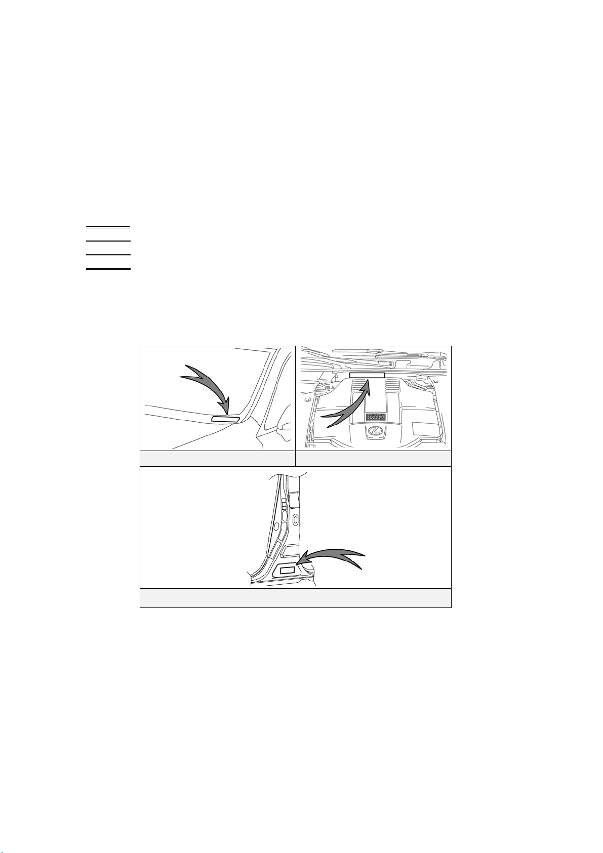
The alphanumeric 17 character Vehicle Identification Number (VIN) is provided in the front
windshield cowl, driver door pillar, and engine compartment.
Example VIN:
JTHCU46F000000001 (LS600h)
JTHDU46F000000001 (LS600hL except for U.S.A. and Canada)
JTHDU1
JTHDU5
An LS600h is identified by the first 6 alphanumeric characters
JTHCU4.
An LS600hL is identified by the first 6 alphanumeric characters
JTHDU4, JTHDU1 or JTHDU5.
EF000000001 (LS600hL (4-seat models) for U.S.A. and Canada)
EF000000001 (LS600hL (5-seat models) for U.S.A. and Canada)
Driver Side Windshield Engine Compartment Cowl
Base of Driver Side B Pillar
2
Page 7
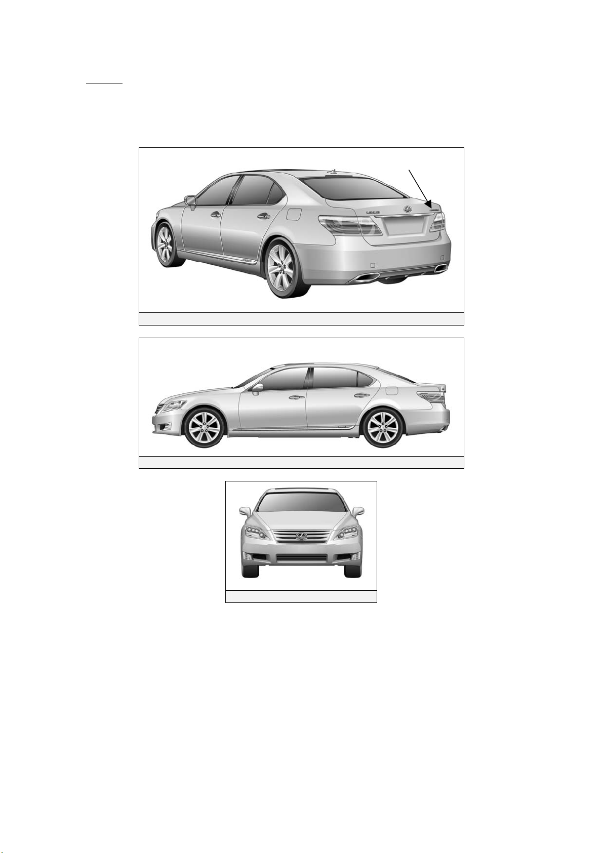
Exterior
LS600h or LS600hL logos on the trunk.
HYBRID logos on the rear door moldings.
Lexus logos that have blue in the background.
LS600h or LS600hL
Exterior Rear and Left Sid e View
Exterior Left Side View
Exterior Front View
3
Page 8
LS600h/LS600hL Identification (Continued)
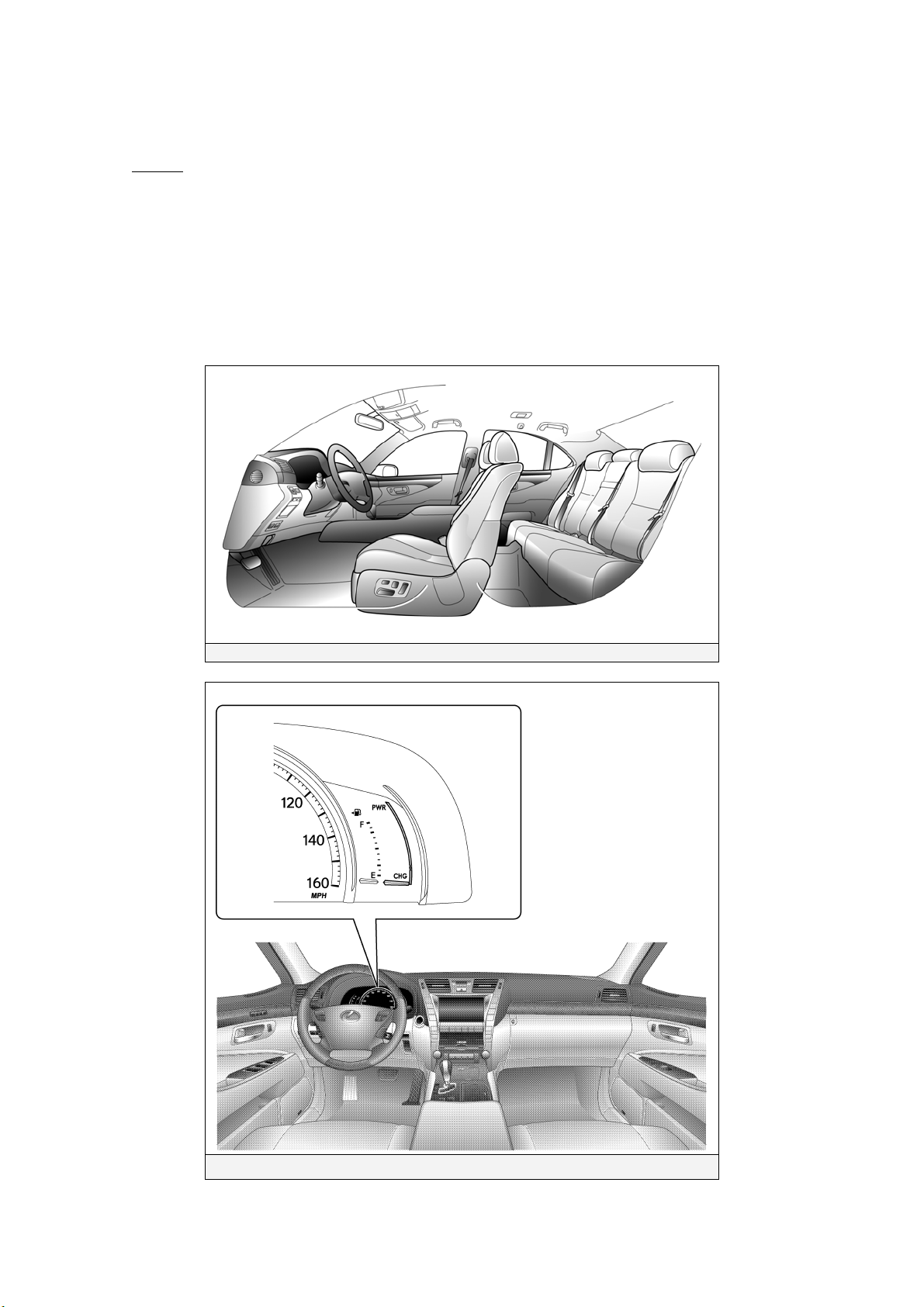
Interior The instrument cluster (speedometer, fuel gauge, warning lights) located in the dash behind
the steering wheel, is different than the one on the conventional, non-hybrid
LS460/LS460L.
The hybrid system indicator (power meter) is located next to the tachometer.
Hint:
If the vehicle is shut off, the instrument cluster gauges will be “blacked out”, not
illuminated.
5-passenger type
Interior View
Instrument Cluster View
4
Page 9
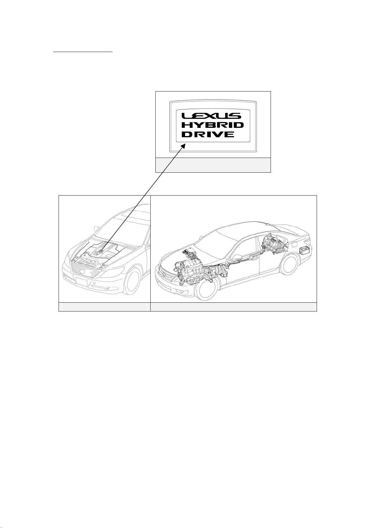
Engine Compartment
5.0-liter aluminum alloy gasoline engine.
Logo on the plastic engine cover.
Orange colored high voltage power cables.
LEXUS HYBRID DRIVE Logo on
Engine cover
Engine Compartment Power Cables
5
Page 10

Hybrid Component Locations & Descriptions
Component* Location Description
12 Volt
Auxiliary
Battery
Hybrid
Vehicle (HV)
Battery Pack
Power
Cables
Inverter/
Converter
Gasoline
Engine
Electric
Generator
Trunk, Driver Side A lead-acid battery that supplies power to the low voltage devices.
Trunk Area, Mounted
behind Rear Seat
Undercarriage and
Engine Compartment
Engine Compartment Boosts and inverts the high voltage electricity from the HV battery
Engine Compartment Provides two functions:
Transmission 3-phase high voltage AC generator that is contained in the
288 Volt Nickel Metal Hydride (NiMH) battery pack consisting of
20 low voltage (14.4 Volt) modules connected in series.
Orange colored power cables carry high voltage Direct Current
(DC) between the HV battery pack, inverter/converter, and A/C
compressor. These cables also carry 3-phase Alternating Current
(AC) between the inverter/converter, electric motor, and generator.
pack to 3-phase AC electricity that drives the electric motor. The
inverter/converter also converts AC electricity from the electric
generator and electric motor (regenerative braking) to DC that
recharges the HV battery pack.
1) Powers the vehicle.
2) Powers the generator to recharge the HV battery pack.
The engine is started and stopped under control of the vehicle
computer.
transmission and recharges the HV battery pack.
Electric
Motor
A/C
Compressor
(with
Inverter)
DC-DC
Converter
for 12 Volt
Auxiliary
Battery
DC-DC
Converter
for EPS and
Active
Stabilizer
Suspension
System
Fuel T ank
and Fuel
Lines
*Numbers in the component column apply to the illustrations on the following page.
Transmission 3-phase high voltage AC permanent magnet electric motor
contained in the transmission and drives the four wheels through
the transfer case and propeller shafts.
Engine Compartment 3-phase high voltage AC electrically driven motor compressor.
Inside HV Battery
Pack in Trunk
On HV Battery Pack Converts 288 Volts from the HV battery pack to 46 Volts for EPS
Undercarriage, Driver
Side and Center
Converts 288 Volts from the HV battery pack to 12 Volts for low
voltage vehicle power.
and active stabilizer suspension system power. Dull yellow
colored sheathing identifies 46 Volt wires that are routed under the
vehicle body to power the EPS and the active stabilizer
suspension system.
The fuel tank provides gasoline via fuel lines to the engine. The
source fuel lines are routed under the vehicle along the cent er
tunnel and the return line is routed along the driver side under the
floor pan.
6
Page 11
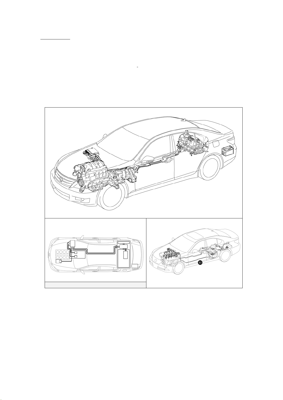
Specifications
Gasoline Engine: 390 hp (290 kW), 5.0-liter Aluminum Alloy Engine
Electric Motor: 221 hp (165 kW), Permanent Magnet Motor
Transmission: Automatic Only
HV Battery: 288 Volt Sealed NiMH
Curb Weight: 5,004-5,357 lbs/2,270-2,430 kg
Fuel Tank: 18.5 Imp gals, 22.1 US gals/84 liter
Frame Material: Steel Unibody, Steel Panels and Aluminum Engine Hood
This illustration is for an LHD model.
Battery
Power Cables
7
Page 12
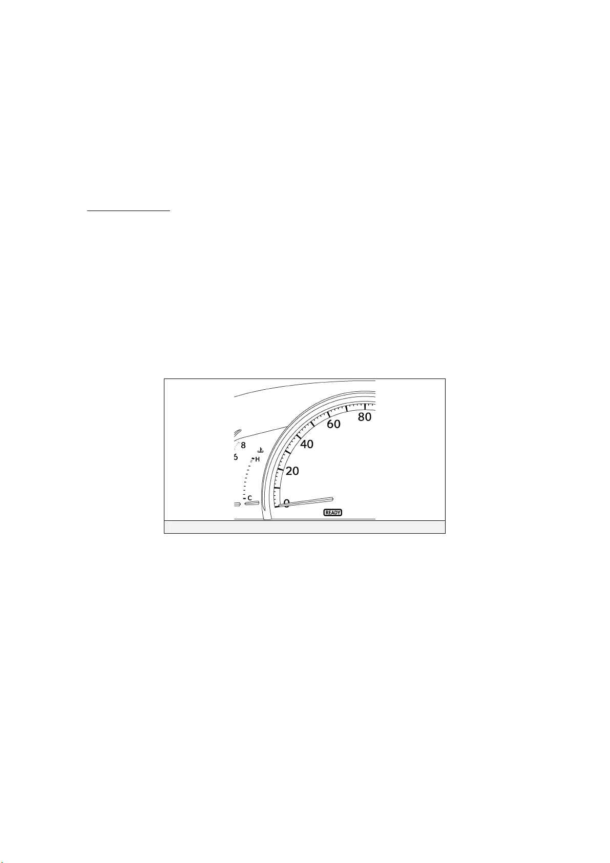
Lexus Synergy Drive Operation
Once the READY indicator is illuminated in the instrument cluster, the vehicle may be
driven. However, the gasoline engine does not idle like a typical automobile and will
start and stop automatically. It is important to recognize and understand the READY
indicator provided in the instrument cluster. When illuminated, it informs the driver
that the vehicle is on and operational even though the gasoline engine may be off and
the engine compartment is silent.
Vehicle Operation
• With the LS600h/LS600hL, the gasoline engine may stop and start at any time while the
READY indicator is on.
• Never assume that the vehicle is shut off just because the engine is off. Always look for
the READY indicator status. The vehicle is shut off when the READY indicator is off.
The vehicle may be powered by:
1. The electric motor only.
2. The gasoline engine only.
3. A combination of both the electric motor and the gasoline engine.
Instrument Cluster READY Indicator
8
Page 13

Hybrid Vehicle (HV) Battery Pack and Auxiliary Battery
•
The LS600h/LS600hL features a high voltage Hybrid Vehicle (HV) battery pack that contains
sealed Nickel Metal Hydride (NiMH) battery modules.
HV Battery Pack
• The HV battery pack is enclosed in a metal case and is securely mounted in the trunk area
behind the rear seat. The metal case is isolated from high voltage and concealed by fabric
covers.
• The HV battery pack consists of 20 low voltage (14.4 Volt) NiMH battery modules
connected in series to produce approximately 288 Volts. Each NiMH battery module is
non-spillable and sealed in a metal case.
• The electrolyte used in the NiMH battery modules is an alkaline mixture of potassium and
sodium hydroxide. The electrolyte is absorbed into the battery cell plates and will not
normally leak, even in a collision.
• In the unlikely event that the battery pack is overcharged, the modules vent gases directly
outside the vehicle through a vent hose.
HV Battery Pack
Battery pack voltage
Number of NiMH battery modules in the pack
NiMH battery module voltage
NiMH battery module dimensions
(16 x 542 x 96 mm)
288 V
20
14.4 V
1 x 21 x 4 in.
NiMH module weight
NiMH battery pack dimensions
NiMH battery pack weight
Components Powered by the HV Battery Pack
• Electric Motor
• Inverter/Converter • Electric Generator
• A/C Compressor
• DC-DC Converter for 12 Volt Auxiliary Battery
• DC-DC Converter for EPS and Active Stabilizer Suspension System
4.8 lbs (2.2 kg)
17 x 33x 17.3 in
(432 x 842 x 439 mm)
174 lbs
(78.9 kg)
Power Cables
9
Page 14

HV Battery Pack Recycling
• The HV battery pack is recyclable. Contact your Lexus Distributor as mentioned on HV
battery Caution Label (see page 37) or the nearest Lexus dealer.
Auxiliary Battery
• The LS600h/LS600hL also contains a lead-acid 12 Volt battery. This 12 Volt auxiliary
battery powers the vehicle electrical system similar to a conventional vehicle. As with
other conventional vehicles, the auxiliary battery is grounded to the metal chassis of the
vehicle.
• The auxiliary battery is located in the trunk area.
288 Volt HV Battery Pack 12 Volt Auxiliary Battery in Trunk
288 Volt HV Battery Pack
(Viewed from the Trunk)
10
Page 15

High Voltage Safety
The HV battery pack powers the high-voltage electrical system with DC electricity. Positive
and negative orange colored high voltage power cables are routed from the battery pack, under
the vehicle floor pan, along the propeller shaft and transmission tunnel to the inverter/converter.
The inverter/converter contains a circuit that boosts the HV battery voltage from 288 to 650
Volts DC. The inverter/converter creates 3-phase AC to power the motor and generator
located in the transmission. Power cables are routed from the inverter/converter to each
high-voltage motor (electric motor, electric generator, and A/C compressor). The following
systems are intended to help keep occupants in the vehicle and emergency responders safe from
high voltage electricity:
High Voltage Safety System
• A high voltage fuse * provides short circuit protection in the HV battery pack.
• Positive and negative high voltage power cables * connected to the HV battery pack are
controlled by 12 Volt normally open relays *. When the vehicle is shut off, the relays
stop electricity flow from leaving the HV battery pack.
WARNING:
・ The high voltage system may remain powered for up to 10
minutes after the vehicle is shut off or disabled. To prevent
serious injury or death from severe burns or electric shock,
avoid touching, cutting, or opening any orange high voltage
power cable or high voltage component.
• Both positive and negative power cables * are insulated from the metal chassis, so there is
no possibility of electric shock when touching the metal chassis.
• A ground-fault monitor continuously monitors for high voltage leakage to the metal chassis
while the vehicle is running. If a malfunction is detected, the hybrid vehicle computer *
will illuminate the master warning light
“CHECK HYBRID SYSTEM” on the multi-information display.
• The HV battery pack relays will automatically open to stop electricity flow in a collision
sufficient to activate the SRS.
*Numbers apply to the illustration on the following page.
in the instrument cluster and indicate
11
Page 16

Service Plug Grip
• The high-voltage circuit is cut by removing the service plug grip (see page 15).
HV Battery Pack
A/C
Compressor
AC
3-Phase
Volt s DC Volt s DC
Inverter/
Converter
Electric Motor
Generator
Hybrid Vehicle
Computer
12 Volts
Auxiliary Battery
High Voltage Safety System – Vehicle Shut Off (READY OFF)
HV Battery Pack
Volt s DC Volt s DC
Inverter/
Converter
A/C
Compressor
AC
3-Phase
Electric Motor
Generator
Hybrid Vehicle
Computer
12 Volts
Auxiliary Battery
High Voltage Safety System – Vehicle On and Operational (READY ON)
12
Page 17

Precaution to be observed when dismantling the vehicle
WARNING:
・ The high voltage system may remain powered for up to 10
minutes after the vehicle is shut off or disabled. To prevent
serious injury or death from severe burns or electric shock,
avoid touching, cutting, or opening any orange high voltage
power cable or high voltage component.
Necessary Items
• Protective clothing such as insulated gloves (electrically insulated), rubber gloves, safety
goggles, and safety shoes.
• Insulating tape such as electrical tape that has a suitable electrical insulation rating.
• Before wearing insulated gloves, make sure that they are not cracked, ruptured, torn, or
damaged in any way. Do not wear wet insulated gloves.
• An electrical tester that is capable of measuring DC 750 Volts or more.
13
Page 18

Spills
The LS600h/LS600hL contains the same common automotive fluids used in other non-hybrid
Lexus vehicles, with the exception of NiMH electrolyte used in the HV battery pack. The
NiMH battery electrolyte is a caustic alkaline (pH 13.5) that is damaging to human tissues.
The electrolyte, however, is absorbed in the cell plates and will not normally spill or leak out
even if a battery module is cracked. A catastrophic crash that would breach both the metal
battery pack case and the battery modules would be a rare occurrence.
A caustic alkaline is at the opposite end of the pH scale from a strong acid. A safe (neutral)
substance is approximately in the middle of this scale. Adding a weak acidic mixture, such as
a dilute boric acid solution or vinegar, to the caustic alkaline electrolyte will cause the
electrolyte to be neutralized. This is similar but opposite to the use of baking soda to
neutralize a lead-acid battery electrolyte spill.
A Lexus Material Safety Data Sheets (MSDS) is attached to this document.
• Handle NiMH electrolyte spills using the following Personal Protective Equipment (PPE):
• Splash shield or safety goggles. A fold down face shield is not acceptable for acid
or electrolyte spills.
• Rubber, latex or nitrile gloves.
• Apron suitable for alkaline.
• Rubber boots.
• Neutralize NiMH electrolyte.
• Use a boric acid solution or vinegar.
• Boric acid solution - 800 grams boric acid to 20 liters water or 5.5 ounces boric
acid to 1 gallon of water.
Dismantling a vehicle
The following 2 pages contain general instructions for use when working on an
LS600h/LS600hL. Read these instructions before proceeding to the HV battery removal
instructions on page 18.
14
Page 19

WARNING:
・ The high voltage system may remain powered for up to 10 minutes
after the vehicle is shut off or disabled. To prevent serious injury or
death from severe burns or electric shock, avoid touching, cutting,
or opening any orange high voltage power cable or any high voltage
component.
1. Shut off the ignition (READY indicator
is off). Then disconnect the cable from
the auxiliary battery negative (-)
terminal.
2. Remove the service plug grip.
(1) Remove the armrest door cap (5-seat models) or rear seat console box lower cover
(4-seat models).
(2) Remove the 4 bolts and service plug cover.
Caution:
Wear insulated gloves for the following 4 steps.
(3) Slide the handle of the service plug grip to the left.
(4) Raise the service plug girp.
(5) Remove the service plug grip.
(6) Apply insulating tape to the socket of the service plug grip to insulate it.
(Example 5-seat Models)
(3)
(4)
(1)
(2)
15
(5)
Page 20

3. Carry the removed service plug grip in your pocket to prevent other staff from
accidentally reinstalling it while you are dismantling the vehicle.
4. Make other staff aware that a
high-voltage system is being
dismantled by using the following
sign: CAUTION: HIGH-VOLTAGE.
DO NOT TOUCH (see page 17).
5. If the service plug grip cannot be
removed due to damage to the rear
Fuse box
portion of the vehicle, remove the IG2
relay.
Caution:
This operation shuts off the HV
system. Be sure to wear insulated
gloves because high voltage is not
shut off inside the HV battery.
When it is possible to remove the
service plug grip, remove it and continue the procedure.
IG2 Relay
6. After disconnecting or exposing a high-voltage connector or terminal, insulate it
immediately using insulating tape. Before touching a bare high-voltage terminal,
wear insulated gloves.
7. Check the HV battery and nearby area for leakage. If you find any liquid, it may be
strong alkaline electrolyte. Wear
rubber gloves and goggles and
neutralize the liquid using a saturated
boric acid solution or vinegar. Then
wipe up the liquid using waste rags
etc.
8. If the electrolyte comes into contact
with your skin, wash the skin
immediately using a saturated boric
acid solution or a large amount of water. If the electrolyte adheres to any article
of clothing, take the clothing off immediately.
9. If the electrolyte comes into contact with your eye(s), call out loudly for help. Do
not rub your eye(s). Instead, wash the eye(s) with a dilute boric acid solution or a
large amount of water and seek medical care.
10. With the exception of HV battery, remove parts by following procedures which are
similar to conventional Lexus vehicles. For the removal of HV battery, refer to
the following pages.
16
Page 21

17
Page 22

Removal of HV battery
WARNING:
・ Be sure to wear insulated gloves when handling high-voltage parts.
・ Even if the vehicle is shut off and the relays are off, be sure to
remove the service plug grip before performing any further work.
・ Power remains in the high voltage electrical system for 10 minutes
even after the HV battery pack is shut off because the circuit has a
condenser that stores power.
・ Make sure that the tester reading is 0 V before touching any
high-voltage terminals which are not insulated.
・ The SRS may remain powered for up to 90 seconds after the
vehicle is shut off or disabled. To prevent serious injury or death
from unintentional SRS deployment, avoid cutting the SRS
components.
1. Recover refrigerant from refrigeration
system.
2. Shut off the ignition (READY indicator
is off).
3. Remove the battery service hole cover.
4. Disconnect the cable from the auxiliary
battery negative (-) terminal.
Battery Service Hole Cover
18
Page 23

5. Remove the service plug grip.
(1) Remove the armrest door cap (5-seat models) or rear seat console box lower cover
(4-seat models).
(2) Remove the 4 bolts and service plug cover.
Caution:
Wear insulated gloves for the following 4 steps.
(3) Slide the handle of the service plug grip to the left.
(4) Raise the service plug grip as shown in the illustration below.
(5) Remove the service plug grip.
(6) Apply insulating tape to the socket of the service plug grip to insulate it.
(Example 5-seat Models)
(1)
(2)
6. Remove the cowl top ventilator louver.
(1) Remove the 4 clips and hood to cowl top seal.
(2) Remove the 6 clips and cowl top ventilator louver.
For LHD
For RHD
(3)
(4)
(5)
19
Page 24

7. Remove the 2 clips and motor cable cover.
For LHD
For RHD
8. Remove the 2 clips and inverter cover assembly.
For LHD
For RHD
9. Remove the 2 bolts and connector cover assembly 10 minutes or more after removal
of the service plug grip.
Caution:
Wear insulated gloves.
Notice:
Do not touch the high voltage connectors or terminals for 10 minutes after the service
plug grip is removed.
For LHD
For RHD
Connecter cover
20
Page 25

10. Check the voltage at the terminals in the inspection point in the inverter/converter.
Caution:
Wear insulated gloves.
To prevent serious injury or death, do not proceed with dismantling of the HV
system until the voltage at the terminals in the inspection point is 0 V.
Standard voltage:
0 V
Hint:
Set the tester to DC 750 Volts measure the voltage.
This inspection is performed to verify that it is safe to remove the HV battery.
For LHD
Inspection Point
For RHD
Inspection Point
21
Page 26

11. Remove the rear seat assembly (Power Seat Type).
(1) Remove the seat cushion assemblies LH and RH.
(2) Remove the center seat cushion assembly.
(3) Cut the seat belts LH and RH.
(4) Remove the rear seatback assemblies LH and RH.
(5) Remove the center seatback assembly.
(6) Remove the rear seatback adjuster assemblies LH and RH.
(3)
(1)
(4)
(6)
(5)
(6)
(4)
(3)
(2)
(1)
Caution:
Do not cut wiring or wire harnesses when removing vehicle components.
Always disconnect components at the connector.
Hint:
When removing rear seat components, it may be necessary to unbolt or move other
components in order to access connectors for components.
22
Page 27

12. Remove the rear seat assembly (Ottoman Power Seat Type).
(1) Remove the seat cushion assemblies LH and RH.
(2) Cut the seat belts LH and RH.
(3) Remove the center console box assembly.
(4) Remove the rear seatback assemblies LH and RH.
(5) Remove the rear seatback adjuster assemblies LH and RH.
(2)
(1)
(4)
*1
(5)
(3)
(5)
(4)
(1)
(2)
This illustration is for an LHD model.
*1: Seat cushion airbag.
Caution:
Do not cut wiring or wire harnesses when removing vehicle components.
Always disconnect components at the connector.
Hint:
When removing rear seat components, it may be necessary to unbolt or move other
components in order to access connectors for components.
23
Page 28

13. Remove the rear seat assembly (Fixed Seat Type).
(1) Remove the rear seat cushion assembly.
(2) Cut the seat belts LH and RH.
(3) Remove the rear seatback assembly.
(2)
(3)
14. Remove the 3 clips and No. 1 center floor
to brace extension.
(1)
(2)
24
Page 29

15. Remove the 3 clips and No. 2 center floor
to brace extension.
16. Remove the 6 bolts and rear console box
bracket lower.
17. Remove the 2 hole plugs.
18. Remove the No. 2 HV battery shield
sub-assembly.
Caution:
Wear insulated gloves.
(1) Using the service plug grip, release the
battery cover lock striker.
(2) Remove the 2 nuts and disconnect the
No. 2 HV battery shield sub-assembly
from the HV battery.
Battery Cover
Lock Striker
Service Plug Grip
25
Page 30

19. Disconnect the frame wire.
(1) Remove the 2 nuts and disconnect the
ends of the frame wire from the HV
battery.
Caution:
Wear insulated gloves.
Notice:
Insulate the terminals of the removed frame
wire with insulating tape.
(2) Remove the battery shield contact from
the HV battery.
20. Remove the nut and remove the air
conditioning tube assembly clamp.
21. Remove the battery room ventilation
Battery Shield Contact
hose.
26
Page 31

22. Remove the 4 upper rope hooks by
pushing the claws in the direction of the
arrows shown in the illustration.
23. Remove the 4 bolts and 4 lower rope
hooks.
24. Remove the clip and deck trim side
board.
25. Remove the No. 1 luggage compartment
light assembly.
(1) Using a screwdriver, disengage the 2
claws and remove the light assembly.
(2) Disconnect the connector.
27
Page 32

26. Remove the front luggage compartment
trim cover.
(1) Remove the 4 claws, 3 clips and front
luggage trim cover (w/o rear air
conditioning).
(2) Remove the 4 claws, remove the 5 clips
and front luggage trim cover (w/ rear air
conditioning).
27. Remove the 3 clips, detach the 4 clips and
finish panel.
28. Remove the 2 clips, detach the claw and
luggage compartment trim cover.
29. Remove the rear door scuff plate LH and
RH.
(1) Remove the 3 clips.
28
Page 33

(2) Remove the 7 claws and rear door scuff
plate.
30. Remove the rear seat side garnish LH and
RH.
31. Remove the inner roof side garnish LH
and RH.
29
Page 34

32. Remove the package tray trim panel
assembly.
(1) Detach the 2 clips of the panel. Then
pass the 3 rear seat belt floor anchors
through the panel.
33. Detach the 5 clips and remove the No. 1
cooler cover (with rear cooler).
34. Remove the clip and No. 2 roof side air
duct LH (with rear cooler).
35. Remove the clip and No. 2 roof side air
duct RH (with rear cooler).
30
Page 35

36. Detach the 4 claws and remove the rear
No. 4 air duct.
37. Detach the 4 claws and remove the rear
No. 5 air duct.
38. Detach the 2 claws and remove the No. 1
cooler air duct (with rear cooler).
39. Detach the 2 claws and remove the No.
2 cooler air duct (with rear cooler).
40. Disconnect the air conditioning tube and
accessory assembly.
(1) Remove the packing.
31
Page 36

(2) Remove the 2 bolts and air conditioning
tube and accessory assembly.
41. Remove the rear cooling unit assembly.
(1) Disconnect the clamps and connectors.
(2) Remove the 4 bolts and rear cooling
unit.
42. Remove the 2 clips and spare wheel
guard sub-assembly.
43. Moving the HV battery.
Caution:
Wear insulated gloves.
(1) Remove the 2 nuts, clamp and wire
harness protector.
(2) Detach the 3 claws and remove the
relay block cover.
32
Page 37

(3) Detach the 2 claws and disconnect the
connector.
(4) Remove the 3 nuts and disconnect the
frame wire from the luggage room
junction block.
Notice:
Insulate the terminal of the removed wire with insulating tape to prevent a short to body
ground.
(5) Remove the 3 nuts and luggage room
junction block.
(6) Disconnect the 2 clamps and connector.
(7) Temporaly install the luggage room
junction block with the 3 nuts.
(8) Remove the 2 nuts and disconnect the 4
clamps, and disconnect the flam wire.
(9) Disconnect the battery pack wire
connector.
33
Page 38

(10) Remove the nut and disconnect the air
conditioning tube assembly
(11) Disconnect the 2 rear active stabilizer
control actuator connectors.
(12) Remove the 2 nuts and power steering
ECU bracket.
(13) Disconnect the 5 connectors.
34
Page 39

(14) Remove the 4 nuts and power steering
converter assembly.
(15) Remove the 4 nuts, 2 bolts and 2 HV
battery brackets.
(16) Remove the 3 bolts for the front part of
the HV battery from the cabin side.
(17) Install the luggage compartment floor
mat upside down.
35
Page 40

(18) Pull out the HV battery onto the
luggage compartment floor mat.
Notice:
When pulling out the HV battery, 2 people
are needed. One should work from the
luggage compartment side and the other
from the cabin side.
Do not allow water in the rear air
conditioning drain hose to spill out.
When pulling out the HV battery, do not
allow the wire harnesses and the HV battery case to interfere with the vehicle body.
When pulling out the HV battery, be careful that the heat insulator on top of the HV
battery does not get caught on parts such as the rear air conditioning unit.
Pull
Hint:
When pulling out the HV battery, moving the HV battery toward the left side of the
vehicle will make this work easier.
44. Remove the HV battery.
Caution:
Wear insulated gloves.
(1) Using an engine sling device, remove the
HV battery from vehicle.
Notice:
Use cardboard or other similar material to
protect the HV battery and vehicle body
from damage.
36
Page 41

HV Battery Caution Label
1. For U.S.A.
2. For CANADA
3. For EUROPE and Others
4. For CHINA
37
 Loading...