

Lexus LS 400 2005 User Manual

A T–1
–AUTOMA TIC TRANSMISSION AUTOMA TIC TRANSMISSION SYSTEM
AUTOMATIC TRANSMISSION SYSTEM
AT033–01
PRECAUTION
If the vehicle is equipped with a mobile communication system, refer to the precautions in the IN section.
2000 LEXUS LS400 (RM717U)
1508Author: Date:
AT–2
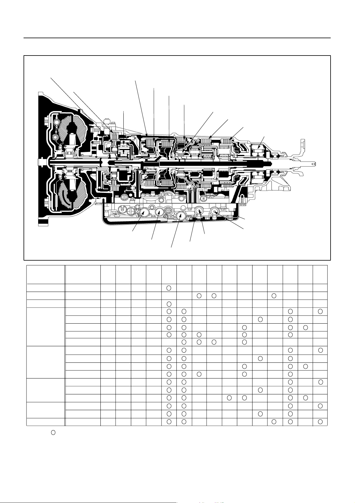
OPERATION
–AUTOMA TIC TRANSMISSION AUTOMA TIC TRANSMISSION SYSTEM
AT034–01
O/D Direct Clutch (C0)
O/D Brake (B0)
Shift Solenoid Valve SLT
3rd Coast Brake (B1)
Direct Clutch (C2)
O/D One–way
Clutch (F0)
Shift Solenoid Valve SLU
Shift Solenoid Valve SLN
Forward Clutch (C1)
3rd Brake (B2)
No.1 One–way Clutch (F1)
2nd Brake (B3)
1st & Reverse Brake (B4)
No.2 One–way Clutch (F2)
Shift Solenoid Valve No.2
Shift Solenoid Valve No.1
Shift Solenoid Valve No.3
Shift Solenoid Valve No.4
D01264
Shift Lever
Position
P
R
N
D
4
3
2
L
Gear
Position
Park
Reverse
Neutral
1st
2nd
3rd
4th
5th
1st
2nd
3rd
4th
1st
2nd
3rd
1st
2nd
1st
: Operating
S1 S2 S3 C0C1C2B0B1B2B3B4F0F1F
ON OFF ON
OFF
ON
OFF
S4
OFF
OFF
OFFON ONONOFF
ON
ON
OFF
OFF
OFF
ON
ON
OFF
OFF
ON
ON
OFF
ON
ON
ON
OFFOFF
ON OFF
ON
OFF
OFF ON
OFF OFF
OFF OFF
OFFON
ON
OFF
OFF
ON
OFF
OFF
OFF
ON
ON
ON
OFF
ON
ON
OFF
OFF
OFF
OFF
OFF
OFF
OFF
OFF
OFF
OFF
OFF
OFF
OFF
OFF
OFF
OFF
OFF
2
2000 LEXUS LS400 (RM717U)
1509Author: Date:
–AUTOMA TIC TRANSMISSION EXTENSION HOUSING OIL SEAL
AT–3
D01008
EXTENSION HOUSING OIL SEAL
AT035–01
ON–VEHICLE REPAIR
1. DRAIN ATF
2. REMOVE FRONT EXHAUST PIPE AND HEAT INSULATOR
(See page AT–16)
3. REMOVE PROPELLER SHAFT
(See page PR–3)
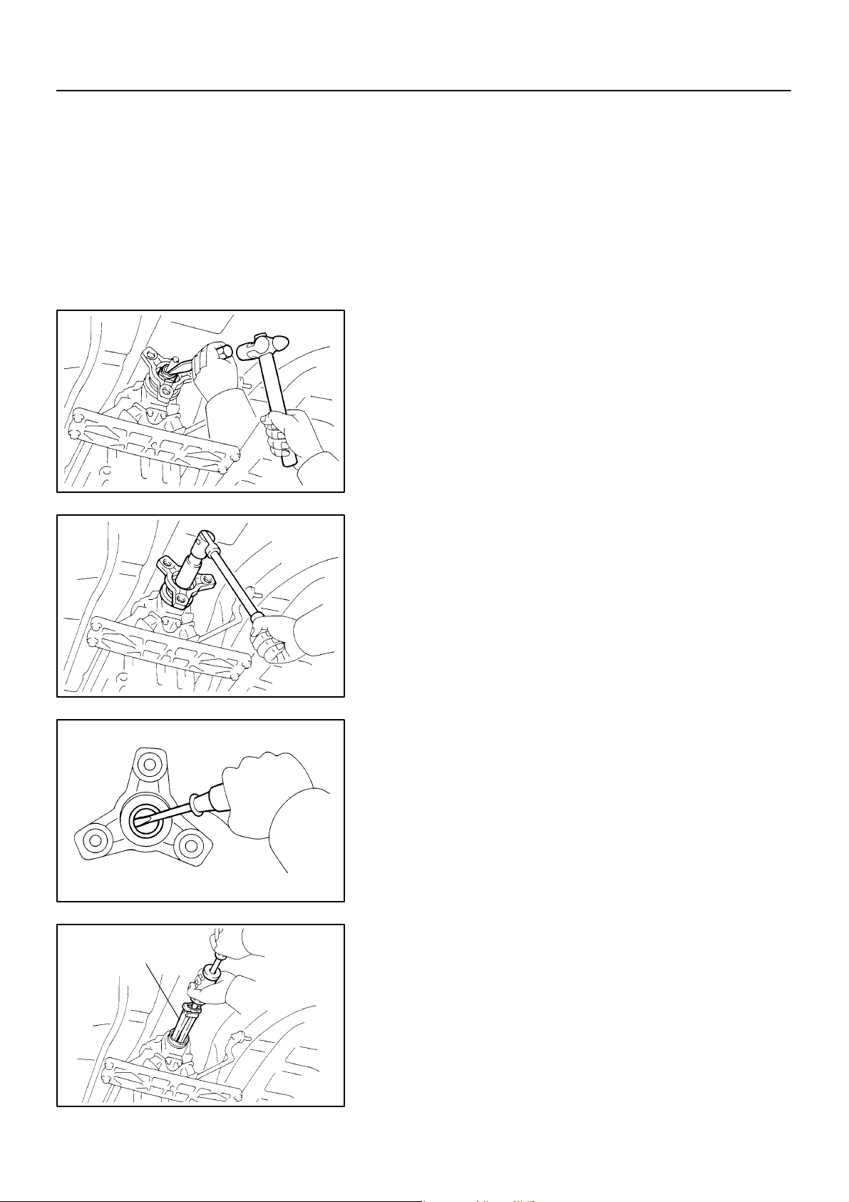
4. REMOVE TRANSMISSION OUTPUT FLANGE
(a) Using a chisel and hammer, loosen the staked part of the
nut.
HINT:
Shift the shift lever to the P position.
(b) Using a 30 mm deeper socket wrench, remove the nut.
(c) Tap the output flange with a plastic hammer to remove it .
SST
D01009
(d) Using a screwdriver, remove the oil seal from the output
flange.
D01010
5. REMOVE EXTENSION HOUSING REAR OIL SEAL
Using SST, remove the oil seal.
SST 09308–00010
D01011
2000 LEXUS LS400 (RM717U)
1510Author: Date:
AT–4
–AUTOMA TIC TRANSMISSION EXTENSION HOUSING OIL SEAL
SST
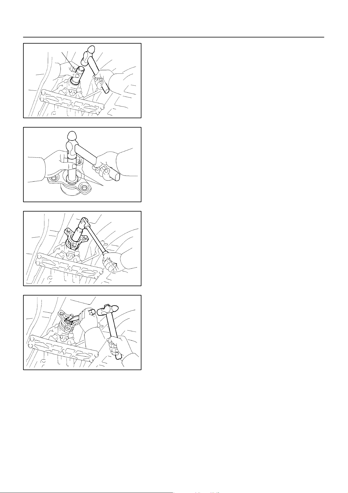
6. INSTALL EXTENSION HOUSING REAR OIL SEAL
(a) Coat the lip of a new oil seal with MP grease.
(b) Using SST and a hammer, drive in the oil seal with the lip
facing downward.
SST 09309–37010
Oil seal depth from flat end: 2.0 mm (0.079 in.)
D01012
7. INSTALL TRANSMISSION OUTPUT FLANGE
(a) Using SST and a hammer, drive in a new oil seal.
SST 09950–60010 (09951–00350), 09950–70010
(09951–07100)
SST
Q08511
(b) Install the output flange.
(c) Using a 30 mm deeper socket wrench, install and torque
a new nut.
Torque: 123 N·m (1,250 kgf·cm, 90 ft·lbf)
HINT:
Shift the shift lever to P position.
D01009
D01008
(d) Using a chisel and hammer, stake the nut.
8. INSTALL PROPELLER SHAFT
(See page PR–9)
9. INSTALL FRONT EXHAUST PIPE AND HEAT INSULATOR
(See page AT–16)
10. FILL AND CHECK FLUID LEVEL
(See page DI–173)
2000 LEXUS LS400 (RM717U)
1511Author: Date:
–AUTOMA TIC TRANSMISSION ATF TEMPERATURE SENSOR
A T–5
ATF TEMPERATURE SENSOR
AT036–01
ON–VEHICLE REPAIR
CAUTION:
When working with FIPG material, you must observe the following items.
Using a razor blade and gasket scraper, remove all the old
FIPG material from the gasket surfaces.
Thoroughly clean all components to remove all the loose
material.
Clean both sealing surfaces with a non–residue solvent.
Apply FIPG in an approx. 1 mm (0.04 in.) wide bead along
the sealing surface.
Parts must be assembled within 10 minutes of application.
Otherwise, the FIPG material must be removed and reapplied.
1. REMOVE DRAIN PLUG WITH GASKET AND DRAIN
AT F
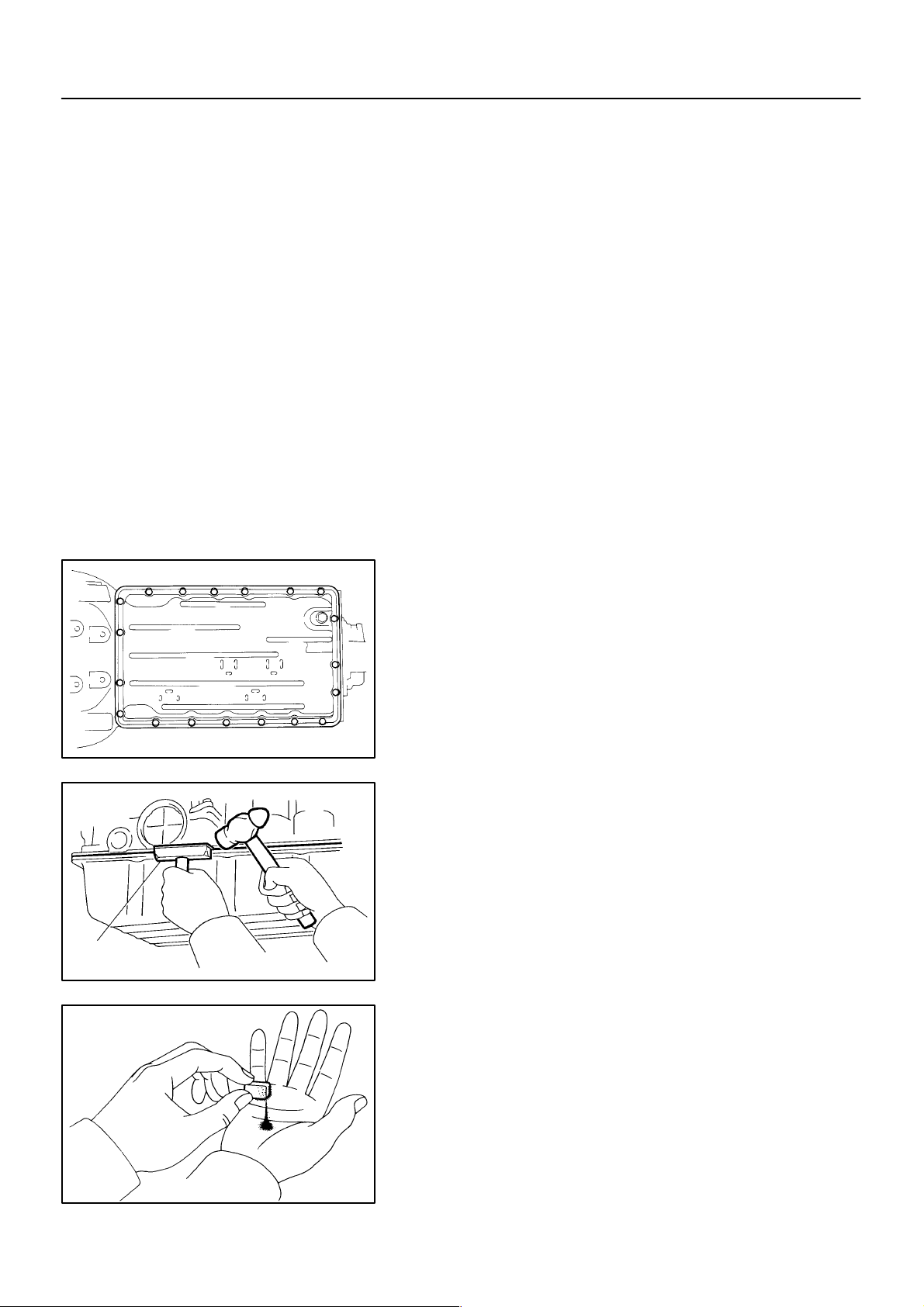
2. REMOVE OIL PAN
NOTICE:
Some fluid will remain in the oil pan.
(a) Remove the 19 bolts.
SST
D00910
(b) Install the blade of SST between the transmission case
and oil pan, cut off applied sealer, and remove the oil pan.
SST 09032 – 00100
NOTICE:
When removing the oil pan, be careful not to damage the oil
pan flange.
Q07487
3. EXAMINE PARTICLES IN PAN
Remove the magnets and use them to collect steel particles.
Carefully look at the foreign matter and particles in the pan and
on the magnets to anticipate the type of wear you will find in the
transmission.
Steel (magnetic) ... bearing, gear and clutch plate wear
Brass (non–magnetic) ... bushing wear
AT0103
2000 LEXUS LS400 (RM717U)
1512Author: Date:
AT–6
–AUTOMA TIC TRANSMISSION ATF TEMPERATURE SENSOR
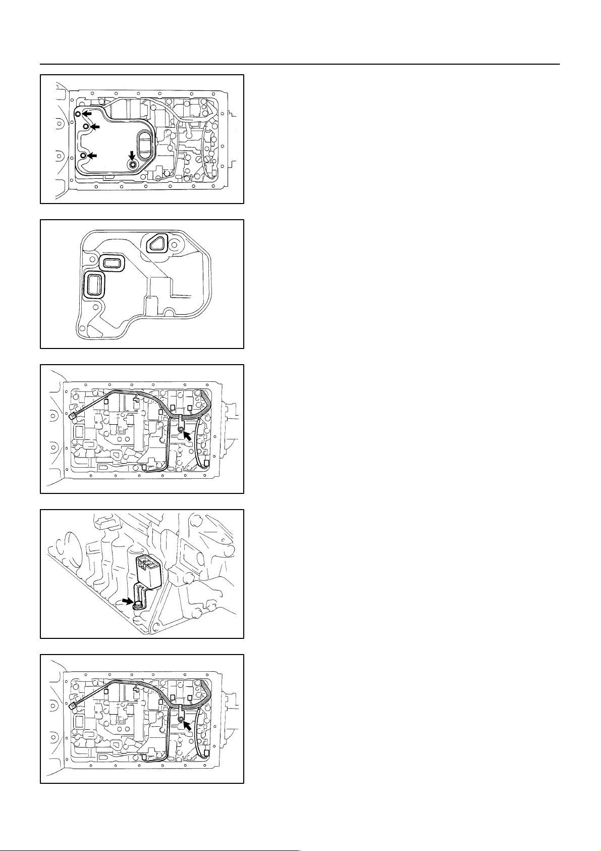
4. REMOVE OIL STRAINER
NOTICE:
Be careful as some fluid will come out of the oil strainer.
(a) Remove the 4 bolts and oil strainer.
D00752
(b) Remove the 3 gaskets from the oil strainer.
D00753
D00909
D00916
5. REMOVE SOLENOID WIRING WITH ATF TEMPERATURE SENSOR
(a) Disconnect the ATF temperature sensor.
(b) Remove the bolt and clamp.
(c) Disconnect the 7 connectors from the solenoid valves.
(d) Remove the bolt and pull out the solenoid connector.
6. INSTALL SOLENOID WIRING WITH ATF TEMPERATURE SENSOR
(a) Install the solenoid connector with the bolt.
Torque: 5.4 N·m (55 kgf·cm, 48 in.·lbf)
2000 LEXUS LS400 (RM717U)
(b) Connect the 7 connectors to the solenoid valves.
(c) Install the clamp with the bolt.
Torque: 6.4 N·m (65 kgf·cm, 56 in.·lbf)
(d) Connect the ATF temperature sensor.
D00909
1513Author: Date:
D00753
A T–7
–AUTOMA TIC TRANSMISSION ATF TEMPERATURE SENSOR
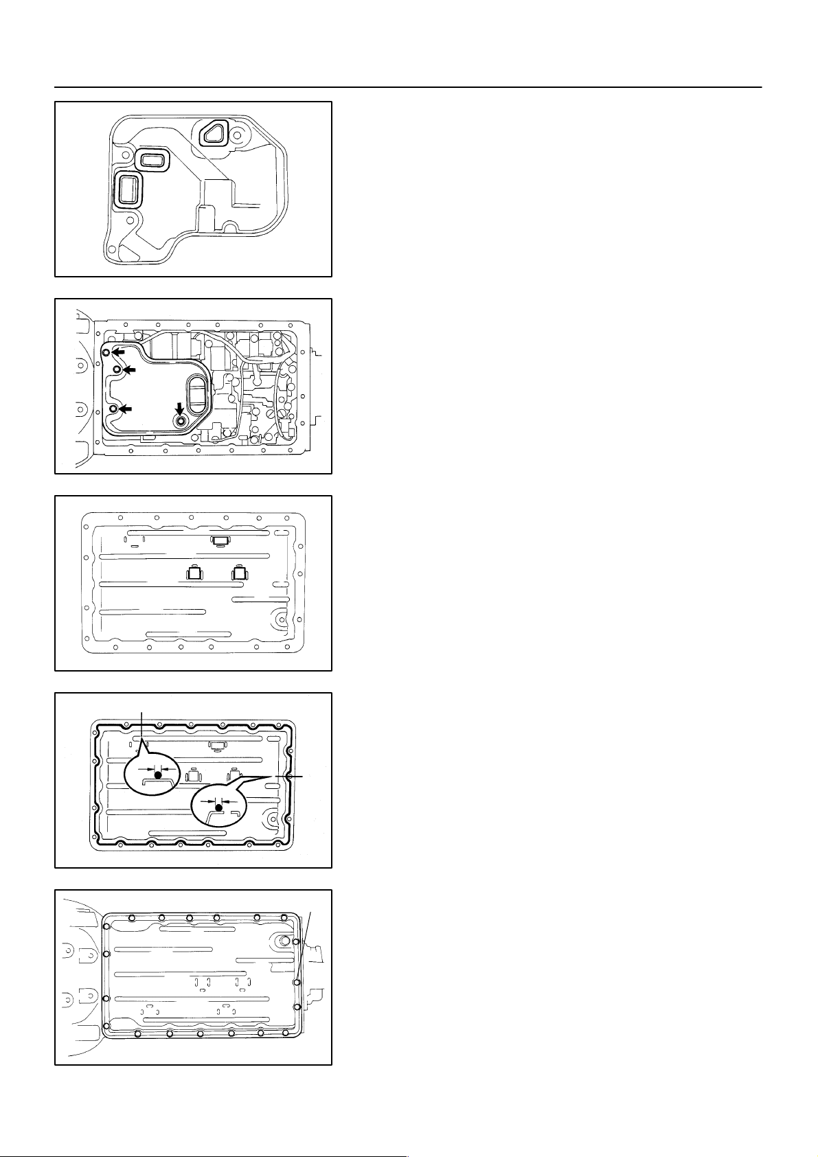
7. INSTALL OIL STRAINER
(a) Install 3 new gaskets.
(b) Install the oil strainer with the 4 bolts.
Torque: 10 N·m (100 kgf·cm, 7 ft·lbf)
Seal Breadth 2 ∼ 3 mm (0.08 ∼ 0.12 in.)
D00752
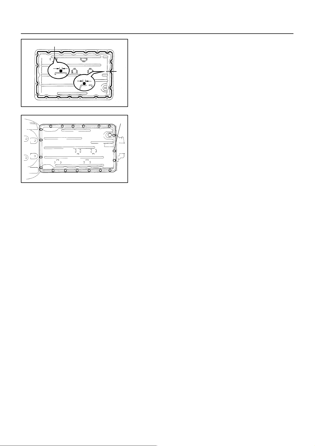
8. INSTALL OIL PAN
(a) Install the 3 magnets in the indications of the oil pan.
D00912
(b) Remove any packing material and be careful not to drop
oil on the contacting surfaces of the transmission case
and oil pan.
(c) Apply FIPG to the oil pan.
FIPG:
Part No. 08826 – 00090, THREE BOND 1281 or
equivalent
D01917
2000 LEXUS LS400 (RM717U)
”A”
D00910
(d) Install the oil pan with the 19 bolts.
Torque: 7.4 N·m (75 kgf·cm, 65 in.·lbf)
HINT:
Replace the only ”A” bolt with a new one.
9. INSTALL DRAIN PLUG WITH NEW GASKET
Torque: 20 N·m (205 kgf·cm, 15 ft·lbf)
10. FILL FLUID AND CHECK FLUID
(See page DI–173)
1514Author: Date:

AT–8
–AUTOMA TIC TRANSMISSION VALVE BODY ASSEMBLY
VALVE BODY ASSEMBLY
AT037–01
ON–VEHICLE REPAIR
CAUTION:
When working with FIPG material, you must observe the following items.
Using a razor blade and gasket scraper, remove all the old
FIPG material from the gasket surfaces.
Thoroughly clean all components to remove all the loose
material.
Clean both sealing surfaces with a non–residue solvent.
Apply FIPG in an approx. 1 mm (0.04 in.) wide bead along
the sealing surface.
Parts must be assembled within 10 minutes of application.
Otherwise, the FIPG material must be removed and reapplied.
1. REMOVE DRAIN PLUG WITH GASKET AND DRAIN
AT F
2. REMOVE OIL PAN
NOTICE:
Some fluid will remain in the oil pan.
(a) Remove the 19 bolts.
SST
D00910
(b) Install the blade of SST between the transmission case
on oil pan, cut off applied sealer, and remove the oil pan.
SST 09032 – 00100
NOTICE:
When removing the oil pan, be careful not to damage the oil
pan flange.
Q07487
3. EXAMINE PARTICLES IN PAN
Remove the magnets and use them to collect steel particles.
Carefully look at the foreign matter and particles in the pan and
on the magnets to anticipate the type of wear you will find in the
transmission.
Steel (magnetic) ... bearing, gear and clutch plate wear
Brass (non–magnetic) ... bushing wear
AT0103
2000 LEXUS LS400 (RM717U)
1515Author: Date:
D00752
AT–9
–AUTOMA TIC TRANSMISSION VALVE BODY ASSEMBLY
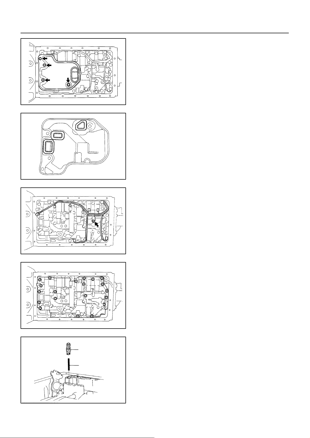
4. REMOVE OIL STRAINER
NOTICE:
Be careful as some fluid will come out of the oil strainer.
(a) Remove the 4 bolts and oil strainer.
(b) Remove the 3 gaskets from the oil strainer.
D00753
D00909
D00754
5. REMOVE SOLENOID WIRING
(a) Disconnect the ATF temperature sensor.
(b) Remove the bolt and clamp.
(c) Disconnect the 7 connectors from the solenoid valves.
6. REMOVE VALVE BODY
Remove the 21 bolts and valve body.
2000 LEXUS LS400 (RM717U)
Check Ball Body
Spring
D01741
7. REMOVE CHECK BALL BODY AND SPRING
NOTICE:
Do not drop the check ball body and spring.
1516Author: Date:

AT–10
–AUTOMA TIC TRANSMISSION VALVE BODY ASSEMBLY
Shift Solenoid
Valve SLN
Shift Solenoid
Valve SLU
Shift Solenoid
Valve SLT
Shift Solenoid
Valve S3
Shift Solenoid
Valve S1
Shift Solenoid Valve S4
Shift Solenoid Valve S2
D00911
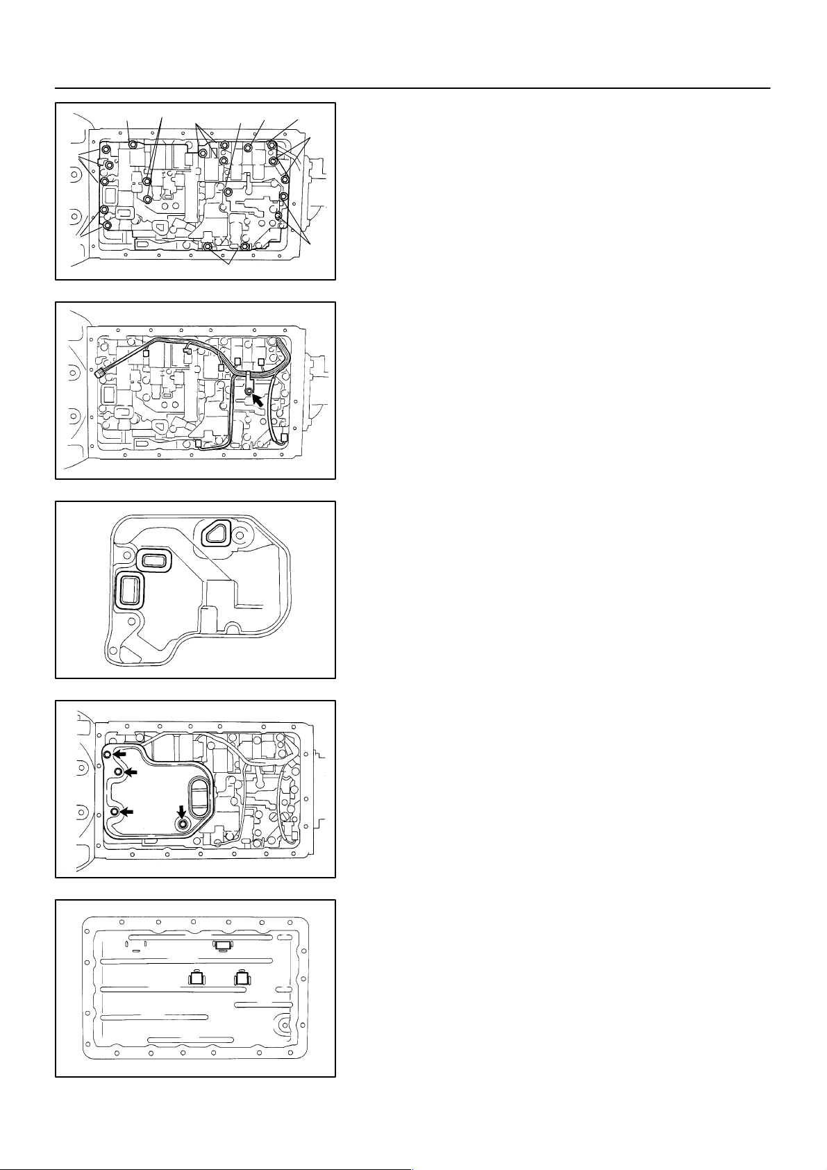
8. REMOVE SOLENOID VALVE
(a) Remove the 3 bolts and shift solenoid valve No.1, No.2
and No.3.
(b) Remove the 2 bolts, oil guide plate, lock plate, shift sole-
noid valve SLN and No.4.
(c) Remove the 6 O–rings from each shift solenoid valve.
(d) Remove the bolt, lock plate and shift solenoid valve SLU
and SLT.
9. INSTALL SOLENOID VALVE
(a) Install the shift solenoid valve SLU and SLT and the lock
plate with the bolt.
Torque: 6.4 N·m (65 kgf·cm, 56 in.·lbf)
(b) Coat 6 new O–rings with ATF.
(c) Install the 6 O–rings to the each solenoid valve.
(d) Install the shift solenoid valve SLN, No.4, lock plate and
oil guide plate with the 2 bolts.
Torque: 10 N·m (100 kgf·cm, 7 ft·lbf)
(e) Install the shift solenoid valve No.1, No.2 and No.3 with
the 3 bolts.
Torque:
Shift solenoid valve No.1 and No.3:
6.4 N·m (65 kgf·cm, 56 in.·lbf)
Shift solenoid valve No.2:
10 N·m (100 kgf·cm, 7 ft·lbf)
Pin
2000 LEXUS LS400 (RM717U)
10. INSTALL CHECK BALL BODY AND SPRING
Check Ball Body
Spring
D01741
11. INSTALL VALVE BODY
(a) Align the groove of the manual valve to pin of the lever.
D00913
1517Author: Date:
–AUTOMA TIC TRANSMISSION VALVE BODY ASSEMBLY
AT–11
B
A
B
B
D
A
C
(b) Install the 21 bolts.
B
Torque: 10 N·m (100 kgf·cm, 7 ft·lbf)
Bolt length:
Bolt A: 23 mm (0.91 in.)
Bolt B: 28 mm (1.10 in.)
Bolt C: 36 mm (1.42 in.)
Bolt D: 55 mm (2.17 in.)
C
C
B
D00754
12. INSTALL SOLENOID WIRING
(a) Connect the 7 connectors to the solenoid valves.
(b) Install the clamp with the bolt.
Torque: 6.4 N·m (65 kgf·cm, 56 in.·lbf)
(c) Connect the ATF temperature sensor.
D00909
13. INSTALL OIL STRAINER
(a) Install 3 new gaskets.
D00753
D00752
D00912
(b) Install the oil strainer with the 4 bolts.
Torque: 10 N·m (100 kgf·cm, 7 ft·lbf)
14. INSTALL OIL PAN
(a) Install the 3 magnets in the indications of the oil pan.
2000 LEXUS LS400 (RM717U)
1518Author: Date:
AT–12
–AUTOMA TIC TRANSMISSION VALVE BODY ASSEMBLY
Seal Breadth 2 ∼ 3 mm (0.08 ∼ 0.12 in.)
D01917
”A”
D00910
(b) Remove any packing material and be careful not to drop
oil on the contacting surfaces of the transmission case
and oil pan.
(c) Apply FIPG to the oil pan.
FIPG:
Part No. 08826 – 00090, THREE BOND 1281 or
equivalent
(d) Install the oil pan with the 19 bolts.
Torque: 7.4 N·m (75 kgf·cm, 65 in.·lbf)
HINT:
Replace the only ”A” bolt with a new one.
15. INSTALL DRAIN PLUG WITH NEW GASKET
Torque: 20 N·m (205 kgf·cm, 15 ft·lbf)
16. FILL FLUID AND CHECK FLUID
(See page DI–173)
2000 LEXUS LS400 (RM717U)
1519Author: Date:
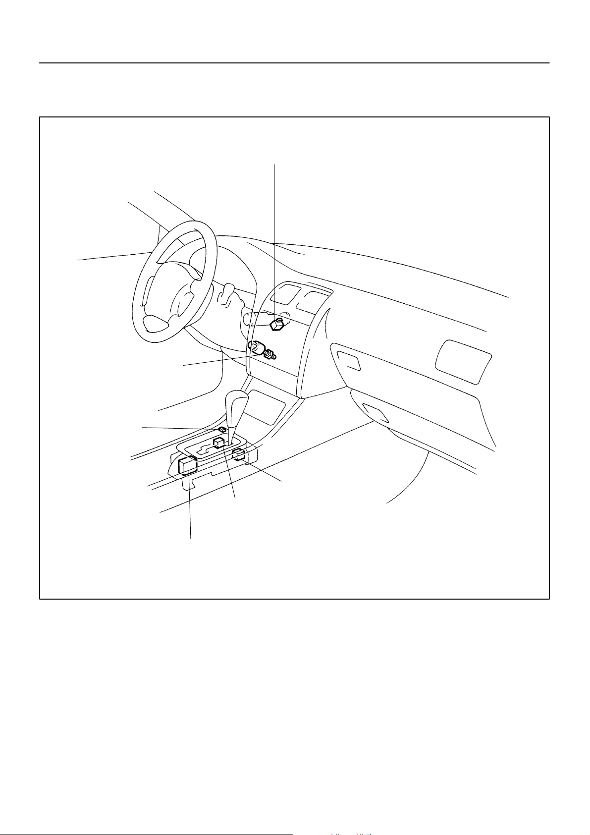
SHIFT LOCK SYSTEM
LOCATION
AT–13
–AUTOMA TIC TRANSMISSION SHIFT LOCK SYSTEM
AT038–01
Key Interlock Solenoid
Stop Light Switch
Shift Lock Override
Button
Shift Lock Solenoid
Shift Lock Control Switch
Shift Lock Control ECU
D01014
2000 LEXUS LS400 (RM717U)
1520Author: Date:
AT–14
A, 3 A, 5 (KLS E)
–AUTOMA TIC TRANSMISSION SHIFT LOCK SYSTEM
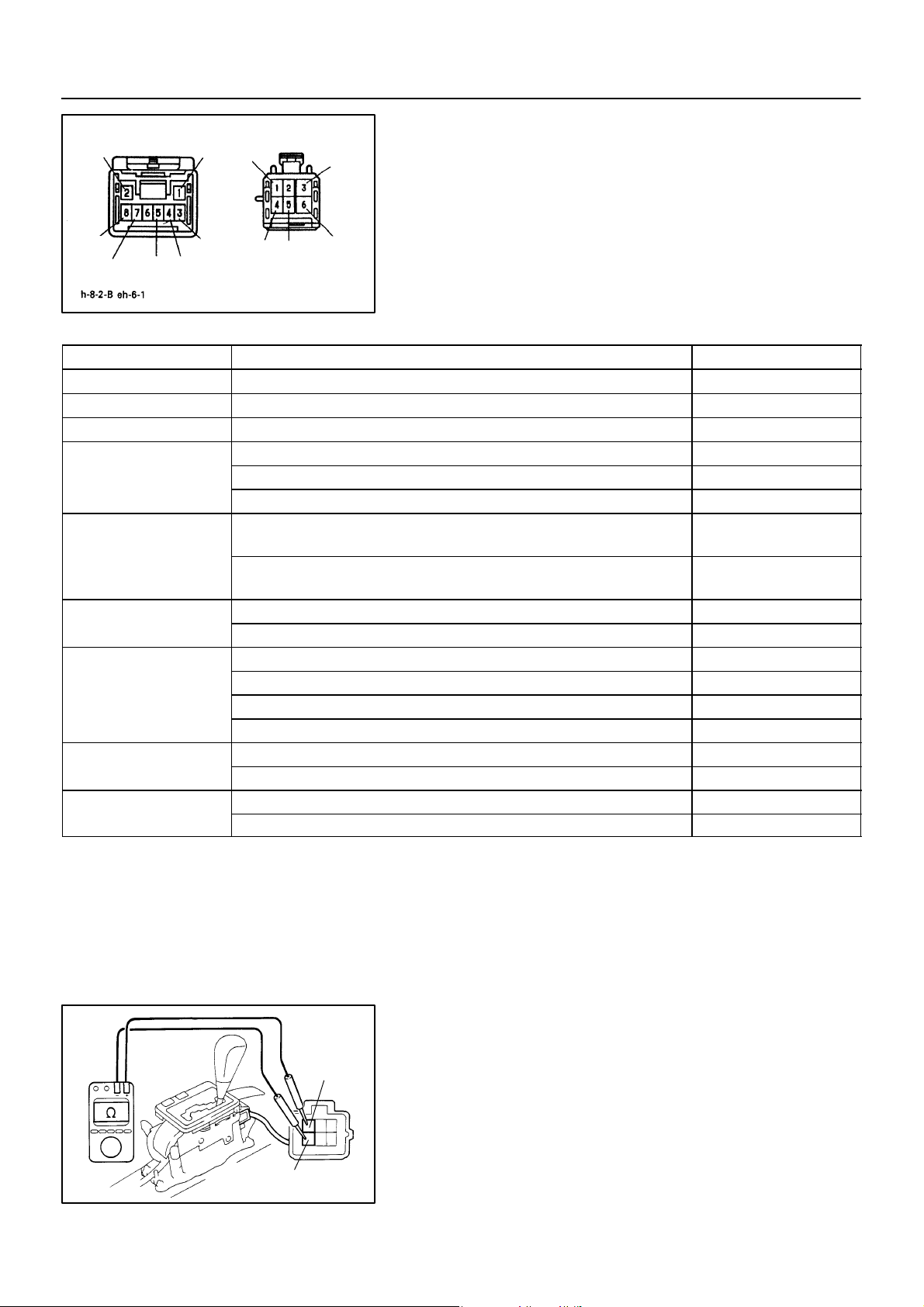
INSPECTION
+
1. INSPECT SHIFT LOCK CONTROL ECU
IG
A
ACC
B
P
SLS
Using a voltmeter, measure the voltage at each terminal.
HINT:
Do not disconnect the ECU connector.
+
STP
KLS
P1P2
SPDDOFF E
Terminal Measuring Condition Voltage (V)
A, 1 – A, 5 (ACC – E) IG SW ACC 10 – 14
A, 2 – A, 5 (IG – E) IG SW ON 10 – 14
A, 8 – A, 5 (STP – E) Depress brake pedal 10 – 14
(1) IG SW ACC and shift lever P position Below 1.5
A, 3 – A, 5 (KLS+ – E)
A, 4 – A, 5 (SPD – E)
A, 7 – A, 5 (DOFF – E)
B, 3 – B, 6 (SLS+ – SLS–)
B, 5 – B, 1 (P1 – P)
B, 4 – B, 1 (P2 – P)
(2) IG SW ON and shift lever R, N, D, 3, 2, L position 8.5 – 10.5
(3) IG SW ON and shift lever R, N, D, 3, 2, L position (after 1 second) 7.0 – 8.5
(1) IG SW ON, shift lever D or 3 position and vehicle speed more than 11 km/h
(6.8 mph)
(2) IG SW ON, shift lever D or 3 position and vehicle speed less than 11 km/h
(6.8 mph)
(1) IG SW ON and shift lever D, 3 position 10 – 14
(2) IG SW ON and shift lever P, R, N, 2, L position 0
(1) IG SW ON and shift lever P position 0
(2) IG SW ON and depress brake pedal 8.8 – 12.5
(3) IG SW ON and depress brake pedal (after 20 seconds) 6.5 – 9.2
(4) IG SW ON and shift lever D, 3, 2, L position 0
(1) IG SW ON and shift lever P position 0
(2) IG SW ON and shift lever R, N, D, 3, 2, L position 10 – 14
(1) IG SW ACC and shift lever P position 10 – 14
(2) IG SW ACC and shift lever R, N, D, 3, 2, L position 0
SLS
Z16912
–
AT039–01
Below 2
10 – 14
2000 LEXUS LS400 (RM717U)
6 (SLS
3 (SLS
–)
+)
D01015
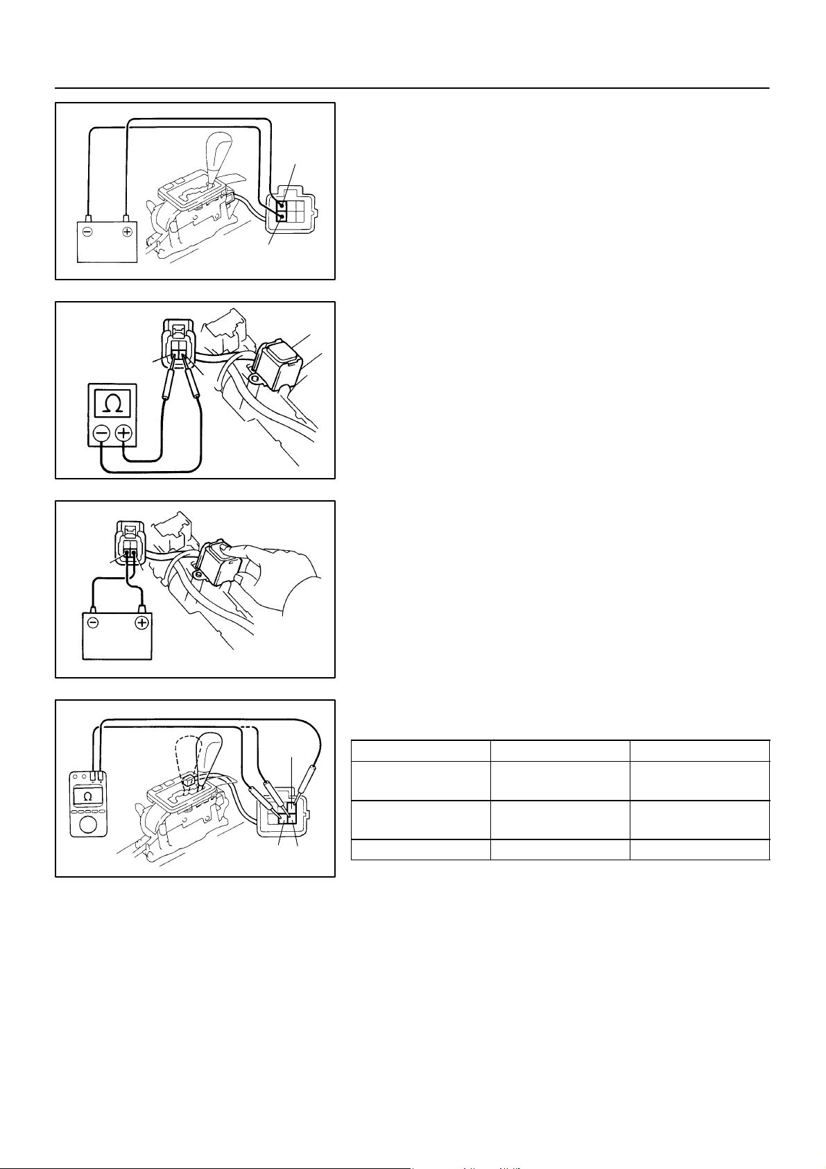
2. INSPECT SHIFT LOCK SOLENOID
(a) Disconnect the solenoid connector.
(b) Using an ohmmeter, measure the resistance between ter-
minals 3 and 6.
Standard resistance: 20 – 28 Ω
If the resistance is not as specified, replace the solenoid.
1521Author: Date:
AT–15
–AUTOMA TIC TRANSMISSION SHIFT LOCK SYSTEM
(c) Apply the battery voltage between terminals 3 and 6. At
this time, confirm that the solenoid operates.
If the operation is not as specified, replace the solenoid.
3 (SLS
6 (SLS
+)
–)
D01016
3. INSPECT KEY INTERLOCK SOLENOID
(a) Disconnect the solenoid connector.
(b) Using an ohmmeter, measure the resistance between ter-
+
–
minals 3 and 4.
Standard resistance: 12 – 17 Ω
If the resistance value is not as specified, replace the solenoid.
Z16909
(c) Touch the solenoid with your finger and check that the so-
lenoid operation can be felt when battery voltage is applied intermittently to terminals 3 and 4.
+
–
Z16910
If the operation is not as specified, replace the solenoid.
4. INSPECT SHIFT LOCK CONTROL SWITCH
Inspect that there is continuity between each terminal.
5 (P1)
1 (P)
4 (P2)
D01017
Shift position Tester condition Specified value
P position (Shift lever at
left side)
P position (Shift lever at
right side)
R, N, D, 3, 2, L position 4 – 1 (P2 – P) Continuity
5 – 1 (P1 – P) Continuity
5 – 1 (P1 – P)
4 – 1 (P2 – P)
Continuity
If the continuity is not as specified, replace the switch.
2000 LEXUS LS400 (RM717U)
1522Author: Date:
AT–16
–AUTOMA TIC TRANSMISSION AUTOMA TIC TRANSMISSION UNIT
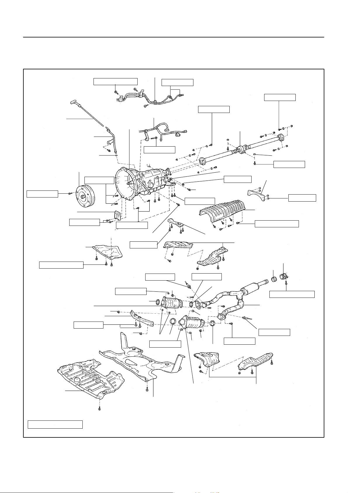
AUTOMATIC TRANSMISSION UNIT
COMPONENTS
Oil Cooler Pipe
Level Gauge
Filler Pipe
O–Ring
Torque Converter Clutch
48 (490, 35)
x6
Flywheel Housing
Under Cover
18 (185, 13)
Engine Rear Mounting
Member Bracket Plate
5.4 (55, 48 in.·lbf)
4.9 (50, 43 in.·lbf)
Wire Harness and Connector
Transmission
72 (730, 53)
37 (380, 27)
37 (380, 27)
Plug for Line Pressure Test
13 (130, 9)
Oxygen Sensor
44 (450, 32)
x6
26 (270, 20)
44 (450, 32)
79 (805, 58)
79 (805, 58)
Propeller Shaft
Adjusting Washer
37 (375, 27)
Shift Control Rod
13 (130, 9)
Plug for Accumulator
Rear Center Floor
Crossmember Brace
Back Pressure Test
Heat Insulator
5.4 (55, 48 in.·lbf)
Front Center Floor Crossmember Brace
Heat Insulator
Clamp
Gasket
43 (440, 32)
AT03A–01
13 (130, 9)
RH Front TWC
Pipe Support Bracket
43 (440, 32)
Engine Under
Cover
N·m (kgf·cm, ft·lbf)
Non–reusable part
62 (630, 46)
Gasket
Front Suspension Protector
: Specified torque
62 (630, 46)
LH Front TWC
See page EM–120
Front Exhaust Pipe
Oxygen Sensor
44 (450, 32)
43 (440, 32)
Gasket
Heat Insulator
D00996
2000 LEXUS LS400 (RM717U)
1523Author: Date:
D00997
A T–17
–AUTOMA TIC TRANSMISSION AUTOMA TIC TRANSMISSION UNIT
AT03B–01
REMOVAL
1. REMOVE LEVEL GAUGE
2. RAISE VEHICLE
NOTICE:
Make sure that the vehicle is securely supported.
3. REMOVE ENGINE UNDER COVER
4. REMOVE FRONT SUSPENSION PROTECTOR
5. REMOVE FRONT EXHAUST PIPE
(a) Disconnect the 2 heated oxygen sensors.
Torque: 44 N·m (450 kgf·cm, 32 ft·lbf)
HINT:
At the time of installation, please refer to the following items.
Before installing the heated oxygen sensor, twist the sen-
sor wire counterclockwise 3 and 1/2 turns.
After installing the heated oxygen sensor wire is not
twisted. If it is twisted, remove the heated oxygen sensor
and reinstall it.
(b) Remove the 4 bolts, nuts and 2 gaskets from the LH and
RH front TWC.
Torque: 43 N·m (440 kgf·cm, 32 ft·lbf)
HINT:
At the time of installation, please refer to the following item.
Replace the used nuts and gaskets with new ones.
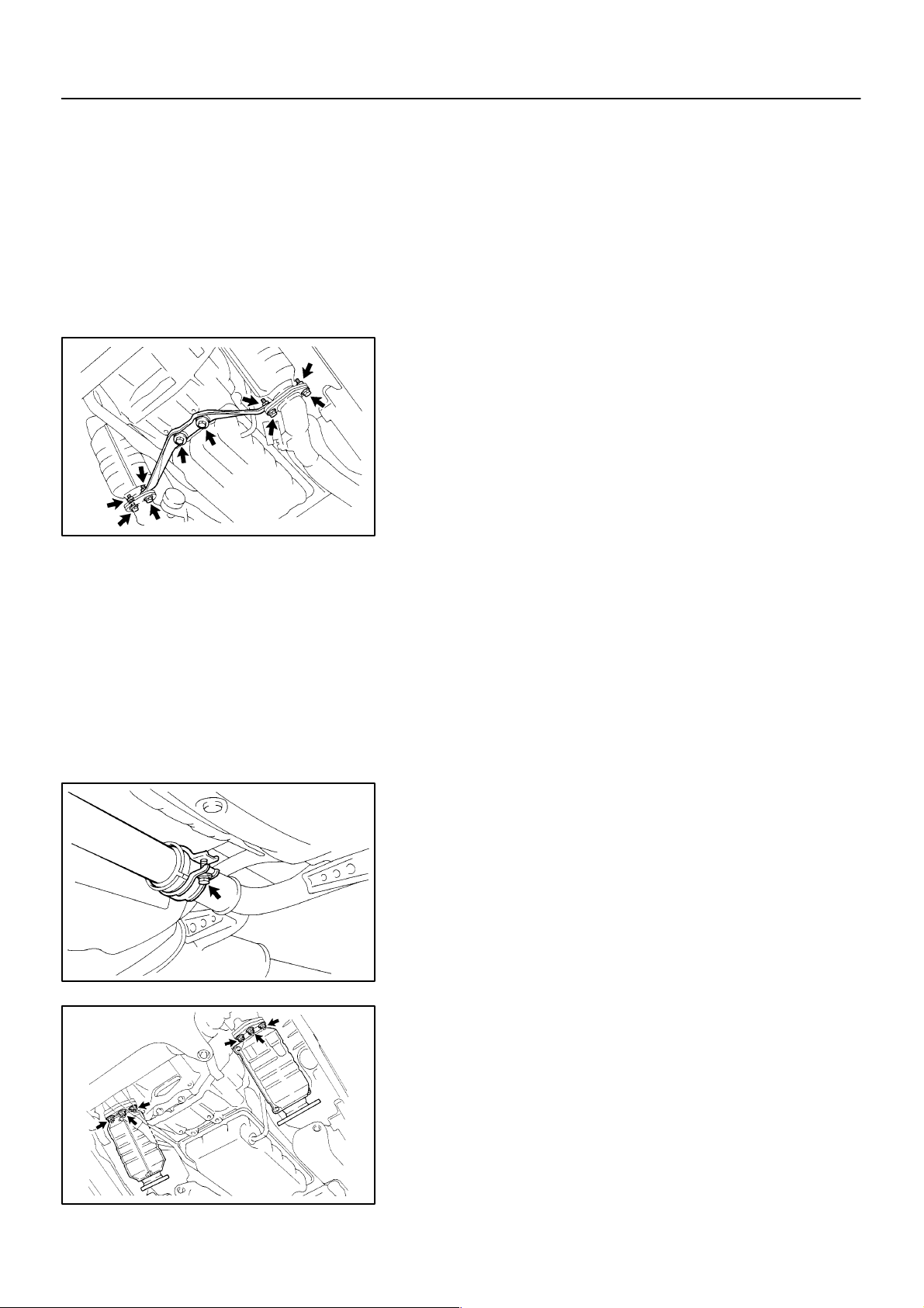
(c) Remove the 2 bolts and support bracket.
Torque: 43 N·m (440 kgf·cm, 32 ft·lbf)
2000 LEXUS LS400 (RM717U)
(d) Remove the pipe clamp set bolt and gasket.
(See page EM–120)
HINT:
At the time of installation, please refer to the following item.
Replace the used gasket with a new one.
(e) Remove the front exhaust pipe.
D00998
6. REMOVE LH AND RH FRONT TWC
Remove the 6 nuts, 2 gaskets, LH and RH front TWC.
Torque: 62 N·m (630 kgf·cm, 46 ft·lbf)
HINT:
At the time of installation, please refer to the following item.
Replace the used nuts and gaskets with new ones.
D00999
1524Author: Date:
AT–18
D01000
–AUTOMA TIC TRANSMISSION AUTOMA TIC TRANSMISSION UNIT
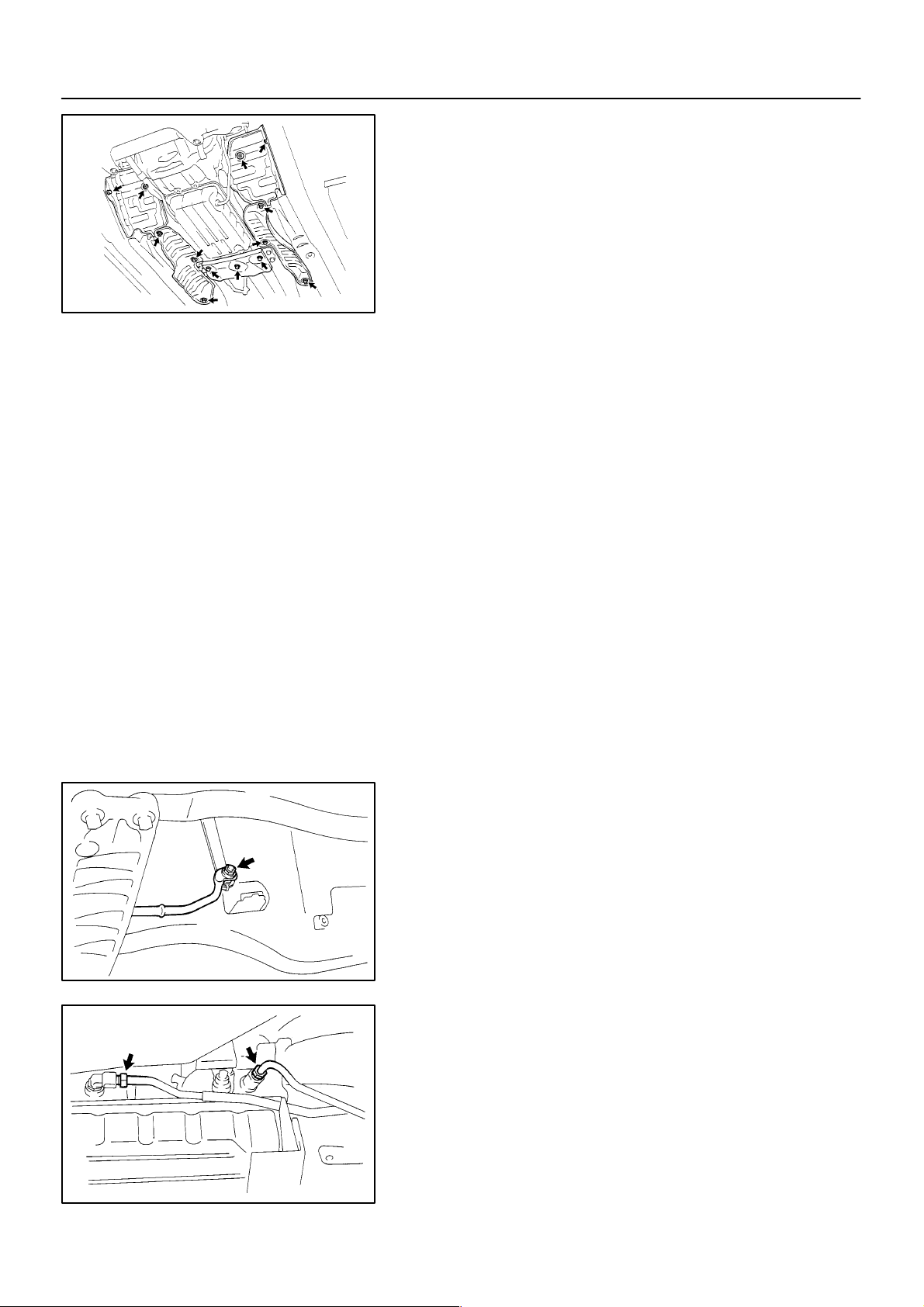
7. REMOVE HEAT INSULATOR AND ENGINE REAR
MOUNTING MEMBER BRACKET PLATE
(a) Remove the 4 nuts, 6 bolts and heat insulators.
(b) Remove the 3 bolts and bracket plate.
Torque: 5.4 N·m (55 kgf·cm, 48 in.·lbf)
8. REMOVE BOLT AND FILLER PIPE
HINT:
At the time of installation, please refer to the following item.
Replace the used O–ring with a new one.
9. REMOVE HEAT INSULATOR
Remove the 6 bolts and heat insulator.
Torque: 5.4 N·m (55 kgf·cm, 48 in.·lbf)
10. REMOVE CROSSMEMBER BRACE
(a) Remove the 4 bolts and front center floor crossmember
brace.
Torque: 13 N·m (130 kgf·cm, 9 ft·lbf)
(b) Remove the 4 nuts and rear center floor crossmember
brace.
Torque: 13 N·m (130 kgf·cm, 9 ft·lbf)
11. REMOVE PROPELLER SHAFT
(See page PR–3)
2000 LEXUS LS400 (RM717U)
12. REMOVE SHIFT CONTROL ROD
Remove the nut and disconnect the rod.
Torque: 13 N·m (130 kgf·cm, 9 ft·lbf)
D01001
13. DISCONNECT OIL COOLER PIPE
(a) Loosen the 2 union nuts from the transmission.
Torque: 44 N·m (450 kgf·cm, 32 ft·lbf)
NOTICE:
Be careful no to damage the oil cooler pipe.
D01002
1525Author: Date:
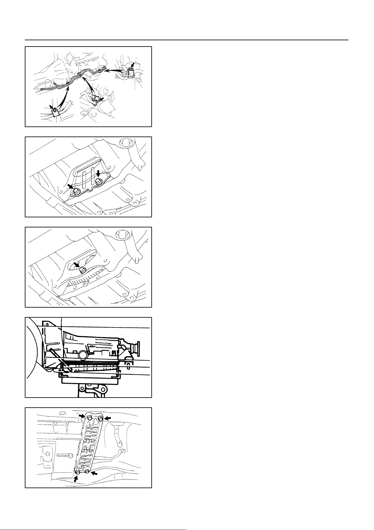
D01003
A T–19
–AUTOMA TIC TRANSMISSION AUTOMA TIC TRANSMISSION UNIT
(b) Disconnect the 3 set bolts of the clamp.
Torque: 4.9 N·m (50 kgf·cm, 43 in.·lbf)
(c) Disconnect the 2 oil cooler pipes from the transmission.
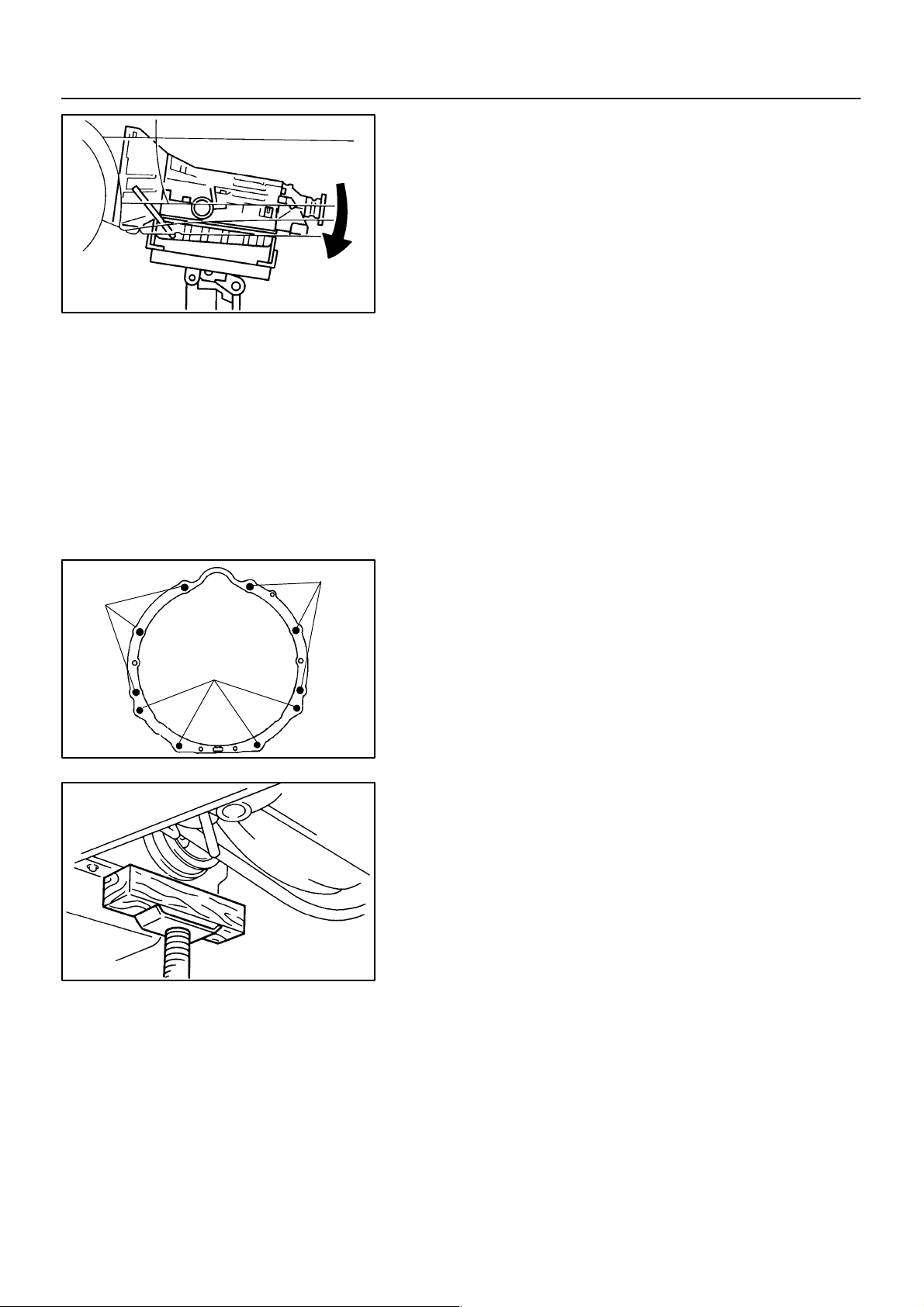
14. REMOVE TORQUE CONVERTER CLUTCH MOUNTING BOLT
(a) Remove the 2 bolts and flywheel housing under cover.
Torque: 18 N·m (185 kgf·cm, 13 ft·lbf)
D01004
D01005
Q03721
(b) Turn the crankshaft to gain access to each bolt.
(c) Hold the crankshaft pulley nut with a wrench and remove
the 6 bolts.
Torque: 48 N·m (490 kgf·cm, 35 ft·lbf)
HINT:
At the time of installation, please refer to the following item.
First install black colored bolt and then the 5 other bolts.
15. SUPPORT TRANSMISSION WITH JACK
2000 LEXUS LS400 (RM717U)
16. REMOVE ENGINE REAR MOUNTING 4 SET BOLTS
Torque: 26 N·m (270 kgf·cm, 20 ft·lbf)
D01006
1526Author: Date:
AT–20
Q06925
–AUTOMA TIC TRANSMISSION AUTOMA TIC TRANSMISSION UNIT
17. DISCONNECT CONNECTORS AND WIRE HARNESS
(a) Tilt down the transmission.
NOTICE:
Take care so that the cooling fan does not come in contact
with the fan shroud.
(b) Disconnect the following connectors:
(1) O/D direct clutch speed sensor connector
(2) Vehicle speed sensor connector
(3) Park/neutral position switch connector
(4) Solenoid connector
(c) Disconnect the wire harness from the clamp on transmis-
sion.
17 mm Head
Bolt
17 mm Head Bolt
14 mm Head Bolt
18. REMOVE TRANSMISSION
Remove the 10 bolts and transmission.
Torque:
14 mm head bolt: 37 N·m (380 kgf·cm, 27 ft·lbf)
17 mm head bolt: 72 N·m (730 kgf·cm, 53 ft·lbf)
Q03099
HINT:
At the time of installation, please refer to the following item.
Lift the engine front side.
Q06924
2000 LEXUS LS400 (RM717U)
1527Author: Date:
D01007
A T–21
–AUTOMA TIC TRANSMISSION AUTOMA TIC TRANSMISSION UNIT
AT03C–01
INSTALLATION
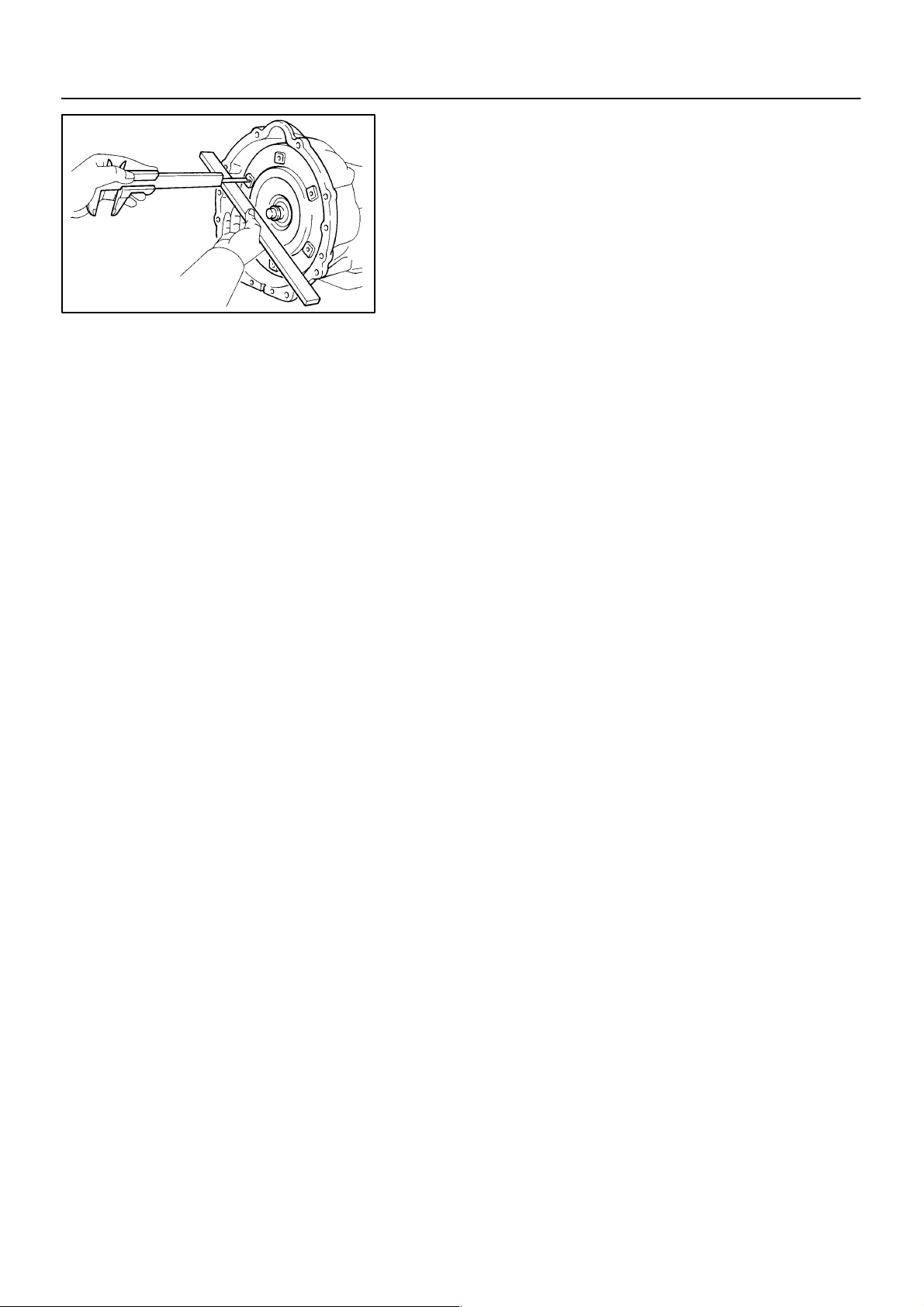
1. CHECK TORQUE CONVERTER CLUTCH INSTALLATION
Using calipers and a straight edge, measure from the installed
surface of the torque converter clutch to the front surface of the
transmission housing.
Correct distance: More than 17.1 mm (0.673 in.)
If the distance is less than the standard, check for an improper
installation.
2. INSTALL TRANSMISSION
Installation is in the reverse order of removal.
(See page AT–17)
HINT:
After installation, check and inspect items as follows.
Adjust the shift lever position. (See page DI–173)
Check fluid level. (See page DI–173)
Do the road test. (See page DI–173)
2000 LEXUS LS400 (RM717U)
1528Author: Date:
AT–22
–AUTOMA TIC TRANSMISSION TORQUE CONVERTER CLUTCH AND DRIVE PLATE
TORQUE CONVERTER CLUTCH
SST
Lock
Free
AT5436
AND DRIVE PLATE
AT03D–01
INSPECTION
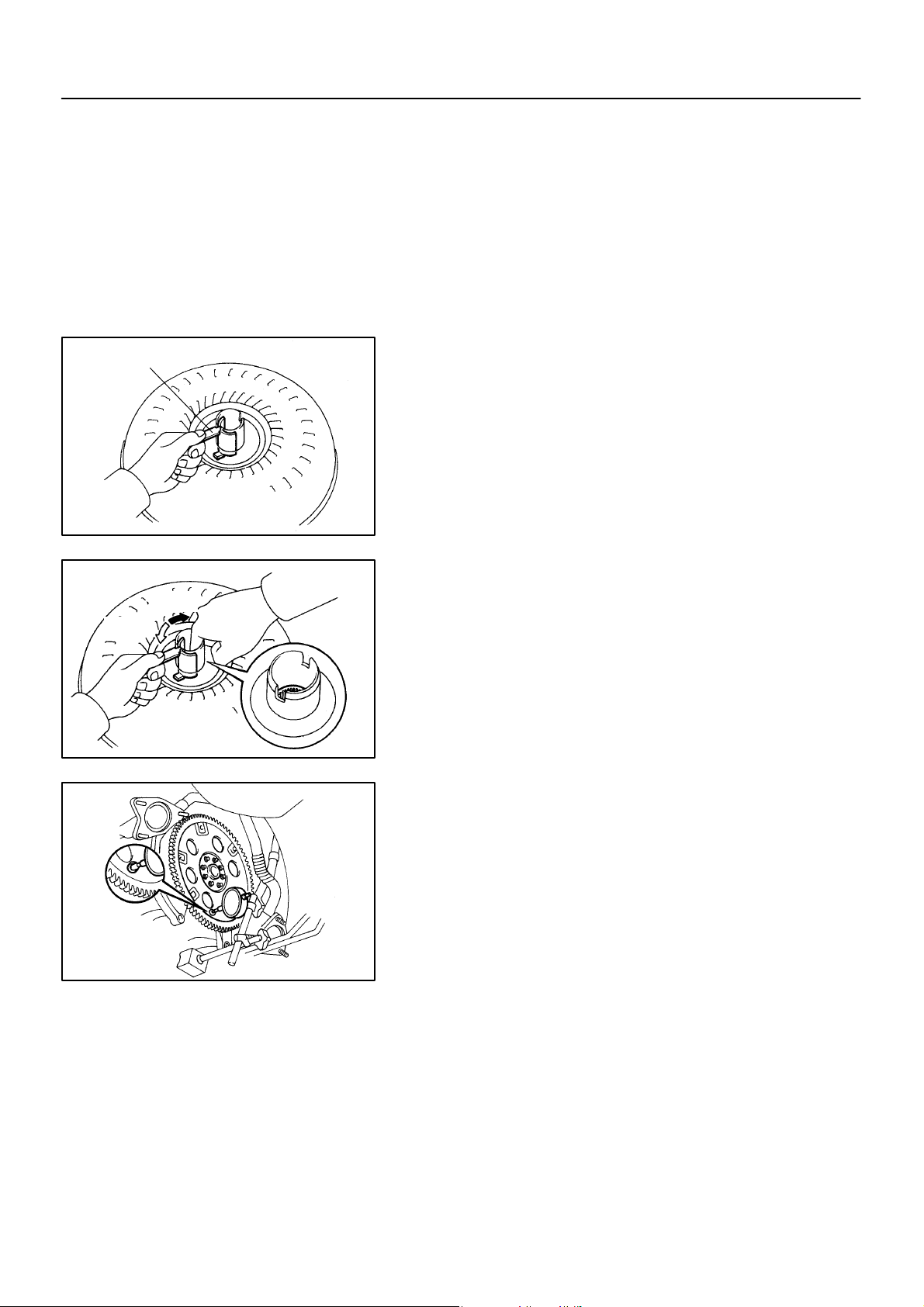
1. INSPECT ONE–WAY CLUTCH
(a) Install SST so that it fits in the notch of the converter hub
and outer race of the one–way clutch.
SST 09350–30020 (09351–32020)
(b) Press on the serrations of starter with a finger and rotate
it.
Check if it rotates smoothly when turned clockwise and
locks up when turned counterclockwise.
AT5437
Q03546
2. MEASURE DRIVE PLATE RUNOUT AND INSPECT
RING GEAR
Set up a dial indicator and measure the drive plate runout.
Maximum runout: 0.20 mm (0.0079 in.)
If runout exceeds 0.20 mm (0.0079 in.) or if the ring gear is damaged, replace the drive plate. If installing a new drive plate, note
the orientation of spacers and tighten the bolts.
Torque: 83 N·m (850 kgf·cm, 61 ft·lbf)
2000 LEXUS LS400 (RM717U)
1529Author: Date:

AT4184
AT–23
–AUTOMA TIC TRANSMISSION TORQUE CONVERTER CLUTCH AND DRIVE PLATE
3. MEASURE TORQUE CONVERTER CLUTCH SLEEVE
RUNOUT
(a) Temporarily mount the torque converter clutch to the drive
plate. Set up a dial indictor.
Maximum runout: 0.30 mm (0.0118 in.)
If runout exceeds 0.30 mm (0.0118 in.), try to correct by reorienting the installation of the torque converter clutch.
If excessive runout cannot be corrected, replace the torque
converter clutch.
HINT:
Mark the position of the torque converter clutch to ensure correct installation.
(b) Remove the torque converter clutch.
2000 LEXUS LS400 (RM717U)
1530Author: Date:

BE–1
–BODY ELECTRICAL BODY ELECTRICAL SYSTEM
BODY ELECTRICAL SYSTEM
BE0DC–01
PRECAUTION
Take care to observe the following precautions when performing inspections or removal and replacement
of body electrical related parts.
1. SUPPLEMENTAL RESTRAINT SYSTEM (SRS)
The Lexus LS400 is equipped with an SRS (Supplemental Restraint System) such as the driver airbag and
front passenger airbag. failure to carry out service operation in the correct sequence could cause the SRS
to unexpectedly deployed during servicing, possibly leading to a serious accident. Before servicing (including removal or installation of parts, inspection or replacement), be sure to read the precautionary codices
in the RS section.
2. COMBINATION METER SYSTEM
The cold cathode tube connectors (Connectors ”N”, ”P” and ”Q”) in the combination meter are charged with
high voltage AC current when power is supplied, so do not touch them when they are charged.
3. MICRO COMPUTER PRESET DRIVING POSITION SYSTEM
Power Seat Control System
Power Mirror Control System
Power Tilt and Telescopic Steering System
If the battery negative (–) terminal is disconnected, the preset driving positions stored in memory are erased,
so be sure to note the positions and reset them after the battery terminal is reconnected.
4. AUDIO SYSTEM
If the battery negative (–) terminal is disconnected, the preset AM, FM 1 and FM 2 stations stored in
memory are erased, so be sure to not the stations and reset them after the battery terminal is reconnected.
If the battery negative (–) terminal is disconnected, the ”ANTI–THEFT SYSTEM” will operate when the
terminal is reconnected, but the radio, tape player and CD player will not operate. Be sure to input the
correct ID number so that the radio, tape player and CD player can be operated again.
2000 LEXUS LS400 (RM717U)
1864Author: Date:

BE–2
–BODY ELECTRICAL BODY ELECTRICAL SYSTEM
5. MOBILE COMMUNICATION SYSTEM
If the vehicle is equipped with a mobile communication system, refer to precautions in the IN section.
6. LIGHTING SYSTEM
Halogen bulbs have pressurized gas inside and require special handling.
They can burst or scatter if scratched or dropped. Hold a bulb only by its plastic or metal case.
Don’t touch the glass part of a bulb with bare hands.
When high voltage socket of discharge headlight is touched with the light control switch HEAD, high
voltage of 20,000 V is momentarily generated. This might lead to a serious accident.
Never connect the tester to the high voltage socket of discharge headlight for measurement, as this
leads to a serious because of high voltage.
When performing operation related to the discharge headlight, make sure to do it in the place with no
water of rain to p r e v e n t e l e c tric shock, with light control switch OFF, battery terminal removed, connector of light control ECU disconnected.
When performing operation related to the discharge headlight, make sure to do it after assembling has
been completely over and never light up without a bulb installed.
Do not light up the discharge headlight using another power source except vehicle’s.
When there is a defect on the discharge headlight or any shock has been applied to it, replace the light
with a new one.
Even if the light operates normally, there is a possibility that the fail–safe function not works.
2000 LEXUS LS400 (RM717U)
1865Author: Date:

BE–3
–BODY ELECTRICAL TROUBLESHOOTING
BE0DD–04
TROUBLESHOOTING
PROBLEM SYMPTOMS TABLE
The table below will be useful for you in troubleshooting these electrical problems. The most likely causes
of the malfunction are shown in the order of their probability. Inspect each part in the order shown, and replace the part when it is found to be faulty.
POWER OUTLET
Symptom Suspect Area See page
1. Battery
Electric power source cannot be taken out of the power outlet
IGNITION SWITCH:
This system uses the multiplex communication system, so check diagnosis system of the multiplex communication system before you proceed with troubleshooting.
Symptom Suspect Area See page
Ignition switch is not set to each position.
KEY UNLOCK WARNING SWITCH:
This system uses the multiplex communication system, so check diagnosis system of the multiplex communication system before you proceed with troubleshooting.
2. RR CIG Fuse (Instrument panel J/B)
3. Wire Harness
1. Ignition switch
2. Power source circuit
BE–33
BE–23
Symptom Suspect Area See page
Key unlock warning system does not operate.
(The buzzer does not sound when the driver’s door is opened with
the ignition OFF and key inserted)
Key unlock warning system does not operate.
(The buzzer sounds when the ignition key is ACC or ON)
1. Key Unlock Warning Switch
2. Door Courtesy Switch
3. Driver Door ECU
4. Multiplex Communication Circuit
5. Body ECU
6. Wire Harness
1. Ignition Switch
2. RADIO No.2 Fuse (Instrument Panel J/B)
3. GAUGE Fuse (Instrument Panel J/B)
4. Wire Harness
BE–33
BE–70
DI–727
DI–838
DI–661
BE–33
HEADLIGHT AND TAILLIGHT SYSTEM:
This system uses the multiplex communication system, so check diagnosis system of the multiplex communication system before you proceed with troubleshooting.
HINT:
To inspect the bulb and light control ECU, replace them with the ones working normally and judge whether
they work normally or not.
(AUTOMATIC LIGHT CONTROL SYSTEM)
Symptom Suspect Area See page
1. ECU–IG Fuse (Instrument Panel J/B)
2. DOME Fuse (Engine Room J/B)
”Automatic light control system” does not operate.
3. Automatic Light Control Sensor
4. Light Control Switch
5. Door Courtesy Switch
6. Body ECU
7. Driver Door ECU
8. Wire Harness
BE–38
BE–38
BE–70
DI–661
DI–727
2000 LEXUS LS400 (RM717U)
1866Author: Date:

BE–4
(AUTO TURN OFF SYSTEM)
Symptom Suspect Area See page
Auto turn–off system does not operate when the driver’s door is
opened.
Headlight and taillight does not come on.
Headlight and taillight stays on.
(USA)
Symptom Suspect Area See page
Only one headlight comes on.
(Headlight main)
Only one headlight comes on.
(Headlight sub)
”LO–Beam” does not light.
”HI–Beam” does not light.
(Headlight main and sub)
”HI–Beam” does not light.
(Headlight main or sub)
”Flash” does not light.
(Headlight main and sub)
”Flash” does not light.
(Headlight main or sub)
Headlight does not come on.
(Headlight main and sub)
–BODY ELECTRICAL TROUBLESHOOTING
1. Drivers Door Courtesy Switch
2. Driver Door ECU
3. Multiplex Communication Circuit
4. Body ECU
1. Body ECU
2. Wire Harness
1. Body ECU
2. Wire Harness
1. H–LP Fuse (LH–LWR) (Engine Room No.1 R/B)
2. H–LP Fuse (RH–LWR) (Engine Room No.1 R/B)
3. Headlight Main Bulb
4. *Light Control ECU
5. Wire Harness
1. H–LP Fuse (LH–UPR) (Engine Room J/B)
2. H–LP Fuse (RH–UPR) (Engine Room J/B)
3. Headlight Sub Bulb
4. *Light Control ECU
5. Wire Harness
1. H–LP Fuse (LH–LWR) (Engine Room No.1 R/B)
2. H–LP Fuse (RH–LWR) (Engine Room No.1 R/B)
3. Headlight Dimmer Relay (Engine Room J/B)
4. Headlight Dimmer Switch
5. Headlight Main Bulb
6. *Light Control ECU
7. Wire Harness
1. H–LP Fuse (LH–UPR) (Engine Room J/B)
2. H–LP Fuse (RH–UPR) (Engine Room J/B)
3. Headlight Dimmer Relay (Engine Room J/B)
4. Headlight Dimmer Switch
5. *Light Control ECU
6. Wire Harness
1. Headlight Main or Sub Bulb
2. *Light Control ECU
3. Wire Harness
1. H–LP Fuse (LH–UPR) (Engine Room J/B)
2. H–LP Fuse (RH–UPR) (Engine Room J/B)
3. Headlight Dimmer Relay (Engine Room J/B)
4. Headlight Dimmer Switch
5. *Light Control ECU
6. Wire Harness
1. Headlight Main or Sub Bulb
2. *Light Control ECU
3. Wire Harness
1. Headlight Control Relay (Engine Room J/B)
2. Headlight Dimmer Relay (Engine Room J/B)
3. Light Control Switch
4. Body ECU
5. *Light Control ECU
6. Wire Harness
BE–70
DI–727
DI–838
DI–661
DI–661
DI–661
BE–38
BE–38
BE–38
BE–38
BE–38
BE–38
BE–38
BE–38
BE–38
BE–38
BE–38
BE–38
BE–38
BE–38
BE–38
BE–38
DI–661
BE–38
2000 LEXUS LS400 (RM717U)
1867Author: Date:

–BODY ELECTRICAL TROUBLESHOOTING
BE–5
Headlight does not come on.
(Headlight main or sub)
Headlight is flicker.
Headlight is dark.
Only one taillight comes on.
Taillight does not come on.
(Headlight is normal)
Taillight does not come on.
(Headlight does not light)
Rear combination light does not come on.
*: HID Type
CANADA:
1. Headlight Main or Sub
2. *Light Control ECU
3. Wire Harness
1. Headlight Main or Sub Bulb
2. Headlight Dimmer Relay (Engine Room J/B)
3. *Light Control ECU
4. Wire Harness
1. Headlight Main or Sub Bulb
2. *Light control ECU
3. Wire Harness
1. Taillight Bulb
2. Wire Harness
1. TAIL Fuse (Instrument Panel J/B)
2. GAUGE Fuse (Instrument Panel J/B)
3. Taillight Control Relay (Instrument Panel J/B)
4. Light Failure Sensor
5. Light Control Switch
6. Body ECU
7. Wire Harness
1. Light Control Switch
2. Wire Harness
1. Light Failure Sensor
2. Wire Harness
3. Bulb
BE–38
BE–38
BE–38
BE–38
BE–38
BE–76
BE–38
DI–661
BE–38
BE–76
Symptom Suspect Area See page
Only one headlight comes on.
(Headlight main)
Only one headlight comes on.
(Headlight sub RH)
Only one headlight comes on.
(Headlight sub LH)
”LO–Beam” does not light (All).
(Headlight main)
”LO–Beam” does not light (One side).
(Headlight main)
”HI–Beam” does not light (All).
(Headlight main)
1. H–LP Fuse (LH) (Engine Room R/B No.1)
2. H–LP Fuse (RH) (Engine Room R/B No.1)
3. Headlight Main Bulb
4. *Light Control ECU
5. Wire Harness
1. H–LP Fuse (LH–UPR) (Engine Room J/B)
2. H–LP Fuse (RH–UPR) (Engine Room J/B)
3. Daytime Running Light No.3 Relay
4. Headlight Sub Bulb
5. *Light Control ECU
6. Wire Harness
1. H–LP Fuse (LH–UPR) (Engine Room J/B)
2. H–LP Fuse (RH–UPR) (Engine Room J/B)
3. Headlight Sub Bulb
4. *Light Control ECU
5. Wire Harness
1. Headlight Dimmer Switch
2. *Light Control ECU
3. Wire Harness
1. Headlight Main Bulb
2. *Light Control ECU
3. Wire Harness
1. Headlight Dimmer Switch
2. *Light Control ECU
3. Wire Harness
BE–38
BE–38
BE–38
BE–38
BE–38
BE–38
BE–38
BE–38
BE–38
2000 LEXUS LS400 (RM717U)
1868Author: Date:

BE–6
–BODY ELECTRICAL TROUBLESHOOTING
”HI–Beam” does not light (One side).
(Headlight main)
”Flash” does not light.
(Headlight main)
Headlight does not come on.
(Headlight main)
Headlight does not come on.
(Headlight sub)
Headlight does not come on with light control switch in HEAD.
(Headlight main)
Headlight does not go out with light control switch in OFF.
(Headlight main
Headlight is flicker.
Headlight is dark.
Taillight does not come on with light control switch in T AIL.
(Headlight main)
Taillight does not go out with light control switch in OFF.
(Headlight main)
Headlight do not come on with engine running and light control
switch in OFF.
(Headlight main)
*: HID Type
1. Headlight Main Bulb
2. *Light Control ECU
3. Wire Harness
1. Headlight Dimmer Switch
2. *Light Control ECU
3. Wire Harness
1. Headlight Control Relay (Engine Room J/B)
2. Daytime Running Light Relay
3. Headlight Dimmer Switch
4. Light Control Switch
5. Body ECU
6. Wire Harness
7. *Light Control ECU
8. Headlight Main Bulb
1. Headlight Dimmer Relay (Engine Room J/B)
2. Daytime Running Light Relay
3. Daytime Running Light No.4 Relay
4. *Light Control ECU
5. Wire Harness
1. Light Control Switch
2. Body ECU
3. *Light Control ECU
4. Wire Harness
1. Headlight Control Relay (Engine Room J/B)
2. *Light Control ECU
3. Wire Harness
1. Headlight Main or sub Bulb
2. Headlight Dimmer Relay (Engine Room J/B)
3. *Light Control ECU
4. Wire Harness
1. Headlight Main or Sub Bulb
2. *Light control ECU
3. Wire Harness
1. Taillight Control Relay (Instrument Panel J/B)
2. Light Control Switch
3. Wire Harness
1. Taillight Control Relay (Instrument Panel J/B)
2. Light Control Switch
3. Wire Harness
1. ECU–B Fuse (Engine Room J/B)
2. GAUGE Fuse (Instrument Panel J/B)
3. DRL Fuse (Engine Room R/B No.1)
4. Daytime Running Light Relay
5. Daytime Running Light No.3 and No.4 Relay
6. Body ECU
7. Generator L Terminal
8. Parking Brake Switch
9. Brake Fluid Level Warning Switch
10. *Light Control ECU
11. Wire Harness
BE–38
BE–38
BE–38
BE–38
BE–38
BE–38
BE–38
DI–661
BE–38
BE–38
BE–38
BE–38
BE–38
BE–38
DI–661
BE–38
BE–38
BE–38
BE–38
BE–38
BE–38
BE–38
BE–38
BE–38
BE–38
BE–38
BE–38
DI–661
BE–98
BE–98
BE–38
2000 LEXUS LS400 (RM717U)
1869Author: Date:

HEADLIGHT BEAM LEVEL CONTROL SYSTEM
Symptom Suspect Area See page
Beam axis is not controlled. (It is not initialized.)
Headlight Beam Level Control System does not operate.
Beam axis is not controlled. (It is initialized.)
Headlight Beam Level Control System does not operate.
Controlled angle of head light is nnusual. (The angle is controlled.)
Beam axis position is not stable during driving.
FOG LIGHT SYSTEM
–BODY ELECTRICAL TROUBLESHOOTING
1. PWR–IG Fuse (Engine Room J/B)
2. Headlight Beam Level Control Actuator
3. Headlight Beam Level Control ECU
4. Wire Harness Side
1. Headlight Beam Level Control ECU
2. Power Source Circuit
3. Height Control Sensor
4. Suspension ECU
5. Headlight Beam Level Control ECU
6. Wire Harness Side
1. Height Control Sensor
2. Suspension ECU
3. Headlights
4. Wire Harness Side
1. ABS System
2. Headlights
3. Wire Harness Side
BE–7
BE–52
BE–52
BE–52
BE–19
DI–251
IN–32
BE–52
DI–251
IN–32
Symptom Suspect Area See page
1. FOG Fuse (Instrument Panel J/B)
Fog light does not light up with light control SW HEAD
(Headlight is normal.)
Fog light does not light up with light control SW HEAD
(Headlight does not light).
Only one light does not light up.
2. Fog Light Relay (Instrument Panel J/B)
3. Fog Light Switch
4. Wire Harness
1. *1 Other Parts
2. Wire Harness
1. Bulb
2. Wire Harness
*1: Inspect Headlight System
TURN SIGNAL AND HAZARD WARNING SYSTEM
Symptom Suspect Area See page
1. Hazard Warning Switch
”Hazard” and ”Turn” do not light up.
The flashing frequency is abnormal.
Hazard warning light does not light up.
(Turn is normal)
Hazard warning light does not light up in one direction.
*1 Turn signal does not light up.
*2 Turn signal does not light up.
2. Turn Signal Switch
3. Turn Signal Flasher
4. Wire Harness
1. Bulb
2. Turn Signal Switch
3. Wire Harness
1. HAZ Fuse (Engine Room J/B)
2. Wire Harness
1. Hazard Warning Switch
2. Wire Harness
1. Ignition Switch
2. TURN Fuse (Instrument Panel J/B)
3. Turn Signal Switch
4. Wire Harness
1. TURN Fuse (Instrument Panel J/B)
2. Turn Signal Switch
3. Wire Harness
BE–56
BE–38
BE–59
BE–38
BE–59
BE–38
BE–59
BE–33
BE–38
BE–38
2000 LEXUS LS400 (RM717U)
1870Author: Date:
 Loading...