

Page 1

BE–1
–BODY ELECTRICAL BODY ELECTRICAL SYSTEM
BODY ELECTRICAL SYSTEM
BE0DC–01
PRECAUTION
Take care to observe the following precautions when performing inspections or removal and replacement
of body electrical related parts.
1. SUPPLEMENTAL RESTRAINT SYSTEM (SRS)
The Lexus LS400 is equipped with an SRS (Supplemental Restraint System) such as the driver airbag and
front passenger airbag. failure to carry out service operation in the correct sequence could cause the SRS
to unexpectedly deployed during servicing, possibly leading to a serious accident. Before servicing (including removal or installation of parts, inspection or replacement), be sure to read the precautionary codices
in the RS section.
2. COMBINATION METER SYSTEM
The cold cathode tube connectors (Connectors ”N”, ”P” and ”Q”) in the combination meter are charged with
high voltage AC current when power is supplied, so do not touch them when they are charged.
3. MICRO COMPUTER PRESET DRIVING POSITION SYSTEM
Power Seat Control System
Power Mirror Control System
Power Tilt and Telescopic Steering System
If the battery negative (–) terminal is disconnected, the preset driving positions stored in memory are erased,
so be sure to note the positions and reset them after the battery terminal is reconnected.
4. AUDIO SYSTEM
! If the battery negative (–) terminal is disconnected, the preset AM, FM 1 and FM 2 stations stored in
memory are erased, so be sure to not the stations and reset them after the battery terminal is reconnected.
! If the battery negative (–) terminal is disconnected, the ”ANTI–THEFT SYSTEM” will operate when the
terminal is reconnected, but the radio, tape player and CD player will not operate. Be sure to input the
correct ID number so that the radio, tape player and CD player can be operated again.
2000 LEXUS LS400 (RM717U)
1864Author!: Date!:
Page 2

BE–2
–BODY ELECTRICAL BODY ELECTRICAL SYSTEM
5. MOBILE COMMUNICATION SYSTEM
If the vehicle is equipped with a mobile communication system, refer to precautions in the IN section.
6. LIGHTING SYSTEM
! Halogen bulbs have pressurized gas inside and require special handling.
They can burst or scatter if scratched or dropped. Hold a bulb only by its plastic or metal case.
Don’t touch the glass part of a bulb with bare hands.
! When high voltage socket of discharge headlight is touched with the light control switch HEAD, high
voltage of 20,000 V is momentarily generated. This might lead to a serious accident.
! Never connect the tester to the high voltage socket of discharge headlight for measurement, as this
leads to a serious because of high voltage.
! When performing operation related to the discharge headlight, make sure to do it in the place with no
water of rain to prevent electric shock, with light control switch OFF, battery terminal removed, connector of light control ECU disconnected.
! When performing operation related to the discharge headlight, make sure to do it after assembling has
been completely over and never light up without a bulb installed.
! Do not light up the discharge headlight using another power source except vehicle’s.
! When there is a defect on the discharge headlight or any shock has been applied to it, replace the light
with a new one.
Even if the light operates normally, there is a possibility that the fail–safe function not works.
2000 LEXUS LS400 (RM717U)
1865Author!: Date!:
Page 3
BE–256
N13360
–
BE0DB–01
INSPECTION
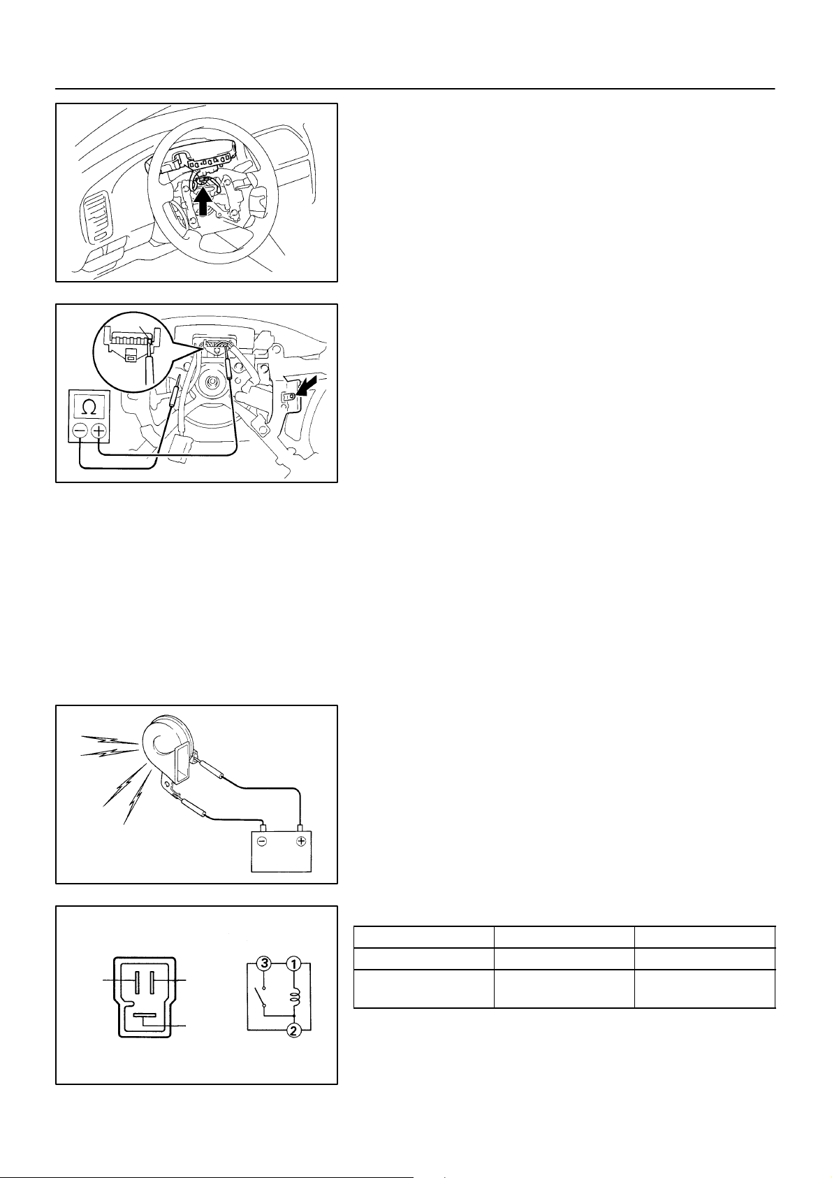
1. INSPECT HORN SWITCH
(a) Disconnect the negative (–) terminal from the battery.
(b) Remove the left and right covers from the steering wheel.
(c) Using a torx socket wrench, loosen the 2 bolts.
(d) Pull up the horn pad and place it on the steering column,
as shown.
HINT:
Do not disconnect the connector from the horn pad.
6
(e) Disconnect the connector from the slip ring.
(f) Check that there is no continuity between terminal 6 of the
connector and body ground.
(g) Check that there is continuity between terminal 6 of the
connector and body ground when the horn contact plate
is pressed against the steering spoke assembly.
If continuity is not as specified, repair or replace the steering
wheel or wire harness as necessary.
I03247
(h) Install the horn pad in place and using a torx socket
wrench, torque the 2 bolts.
Torque: 7.1 N·m (72 kgf·cm, 62 in.·lbf)
(i) Install the left and right covers.
(j) Connect the negative (–) terminal to the battery.
2. INSPECT HORN OPERATION
Connect the positive (+) lead from the battery to the terminal
and negative (–) lead to the horn body and check that the horn
blows.
If operation is not as specified, replace the horn.
I03248
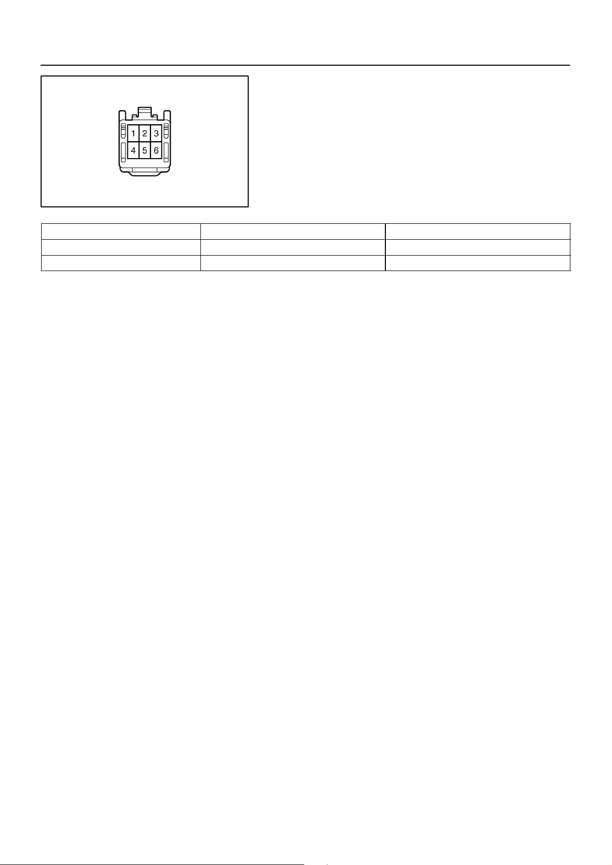
3. INSPECT HORN RELAY CONTINUITY
Condition Te s te r c o nn e c t i on Specified condition
Constant 1 – 2 Continuity
2
3
1
Z08505
Apply B+ between
terminals 1 and 2.
2 – 3 Continuity
If continuity is not as specified, replace the relay.
2119Author!: Date!:
Page 4
HORN SYSTEM
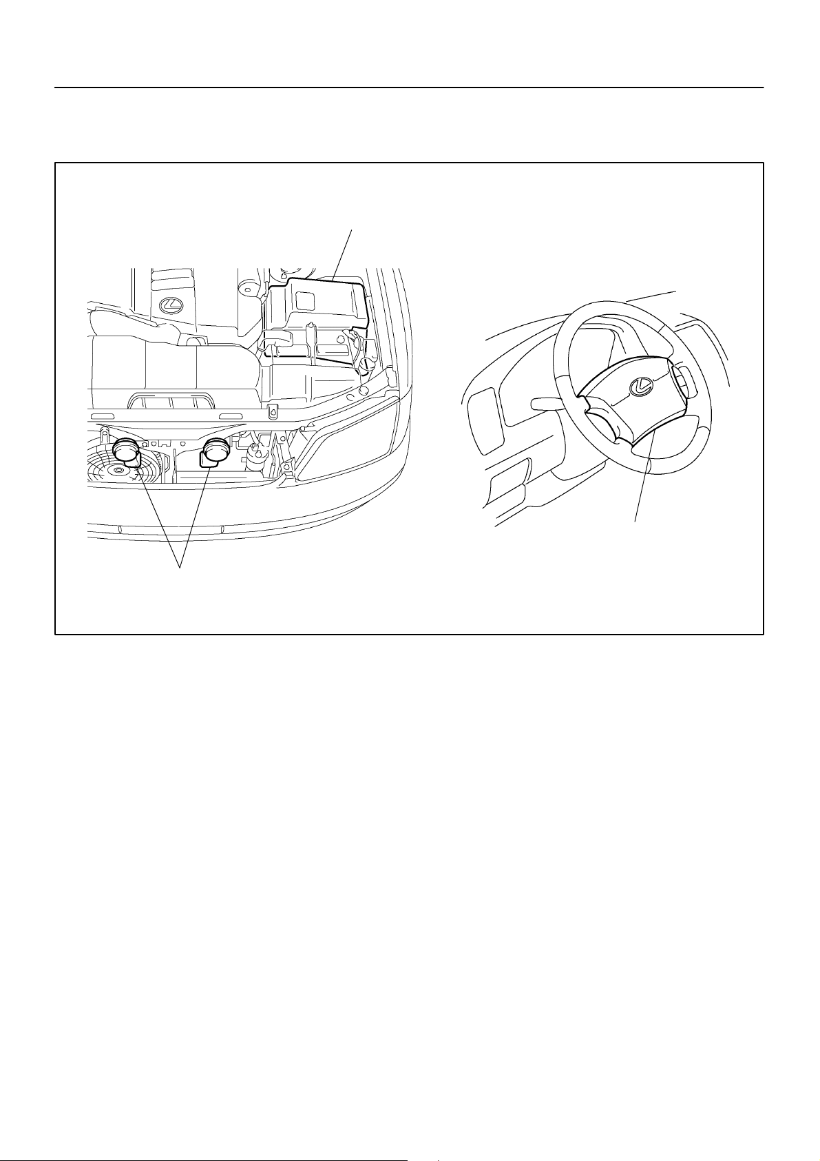
LOCATION
BE–255
–
BE0DA–01
Engine Room Junction Block
! Horn Relay
! HORN Fuse
Horn
Horn Switch
I03238
2118Author!: Date!:
Page 5
BE–254
–
BE0D9–01
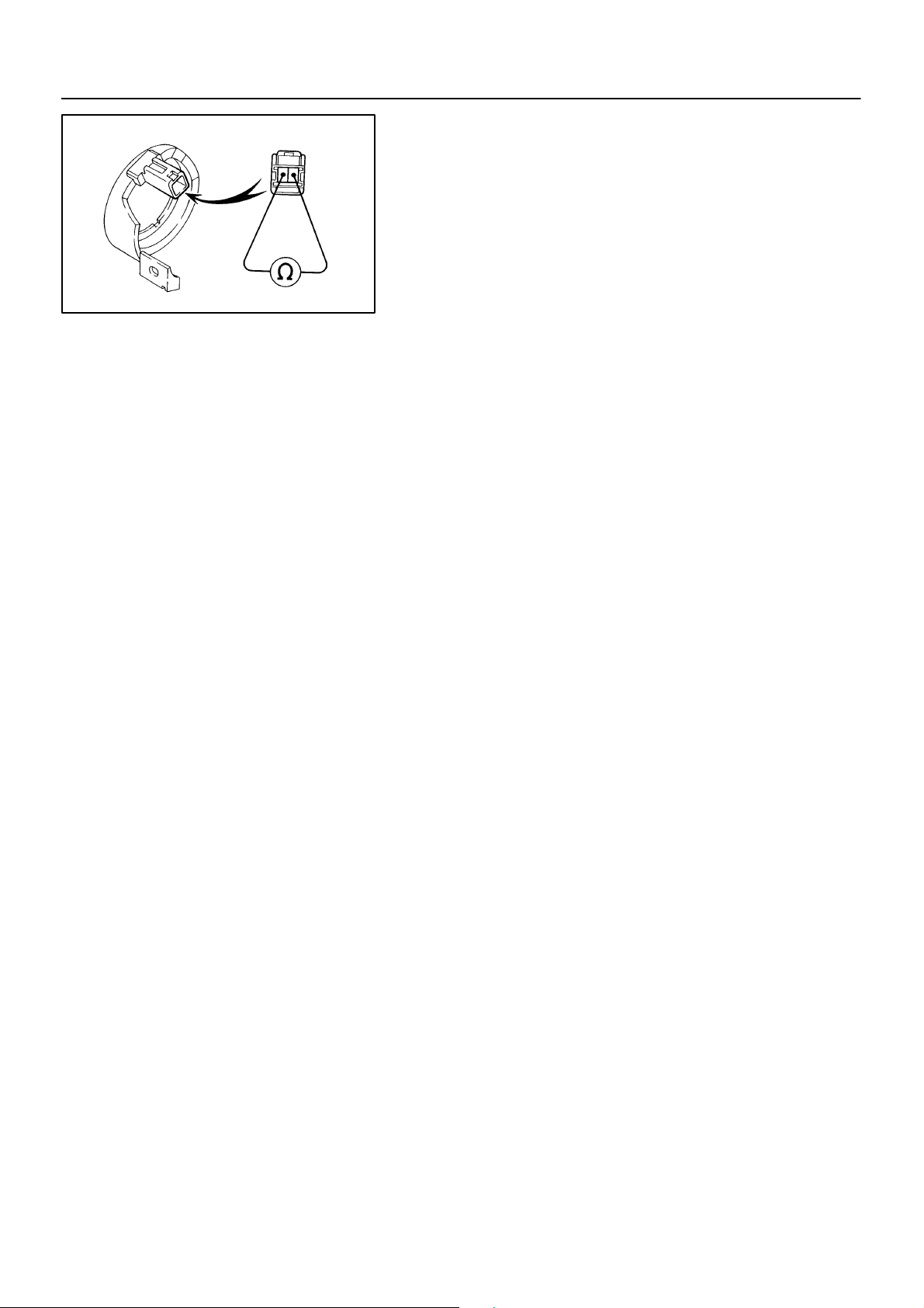
INSPECTION
INSPECTION TRANSPONDER KEY COIL CONTINUITY
Check that there is continuity between terminal 1 and 2.
If continuity is not as specified, replace the coil.
N17185
2117Author!: Date!:
Page 6
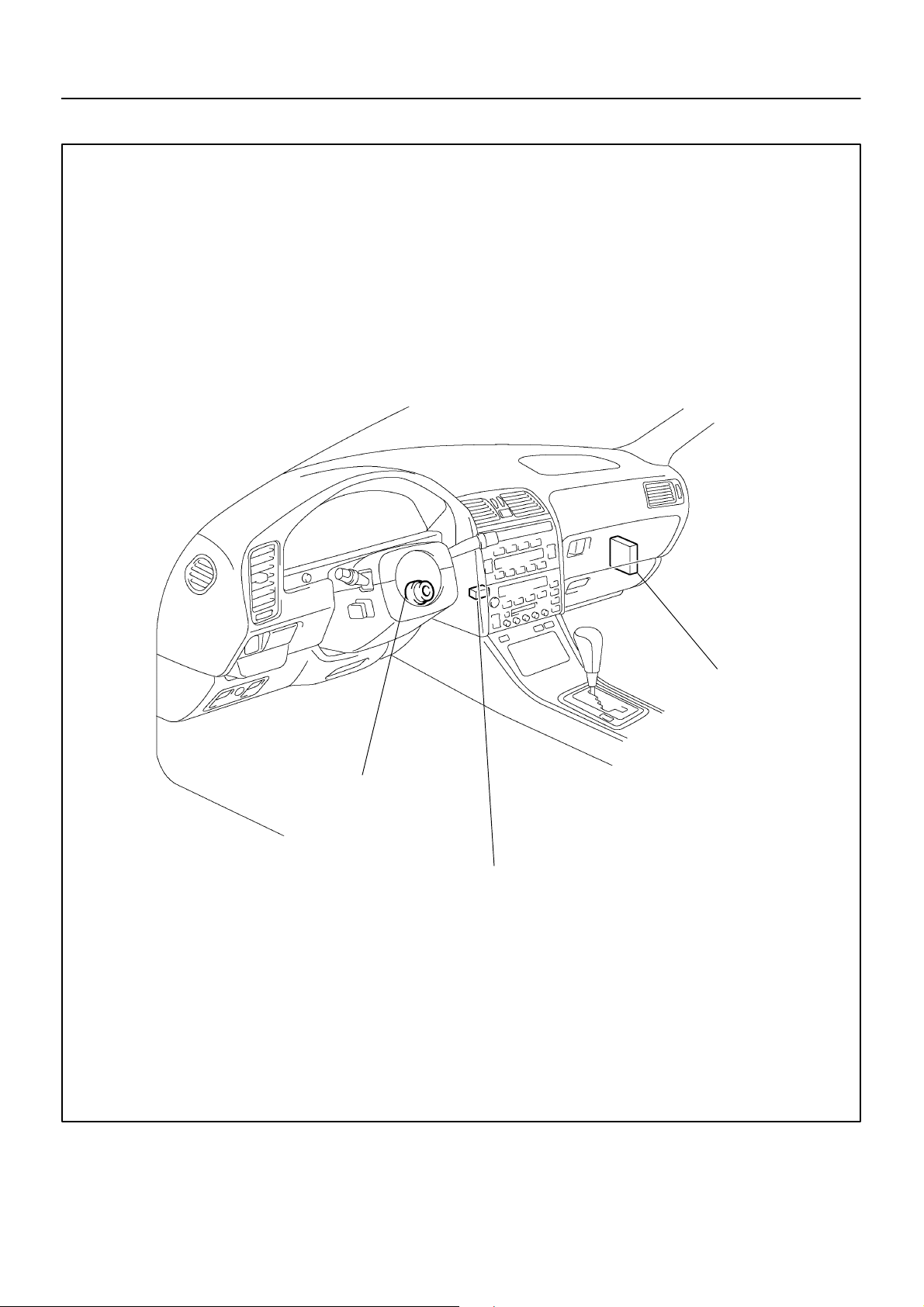
LOCATION
BE–253
–
BE0D8–01
Transponder Key
Coil
ECM
Transponder Key
Amplifier
I03461
2116Author!: Date!:
Page 7
BE–244
–BODY ELECTRICAL ENGINE IMMOBILISER SYSTEM
ENGINE IMMOBILISER SYSTEM
BE0D7–01
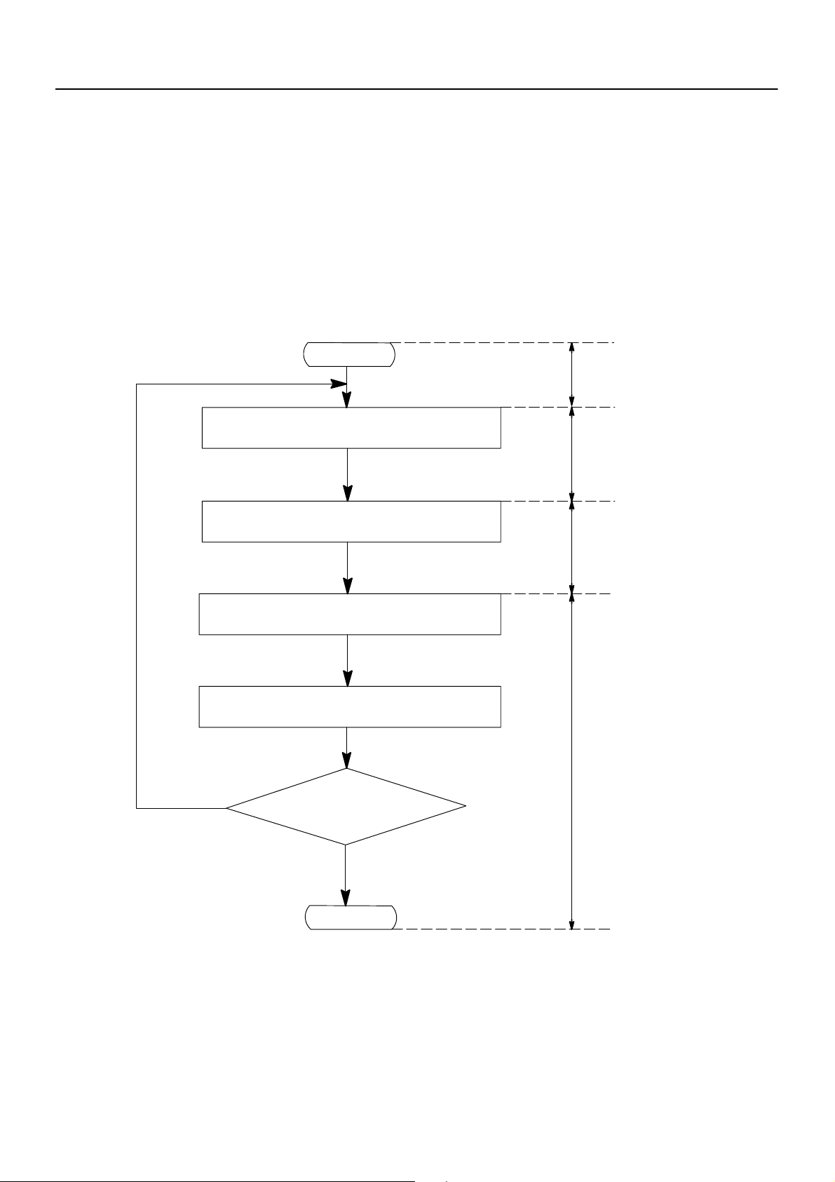
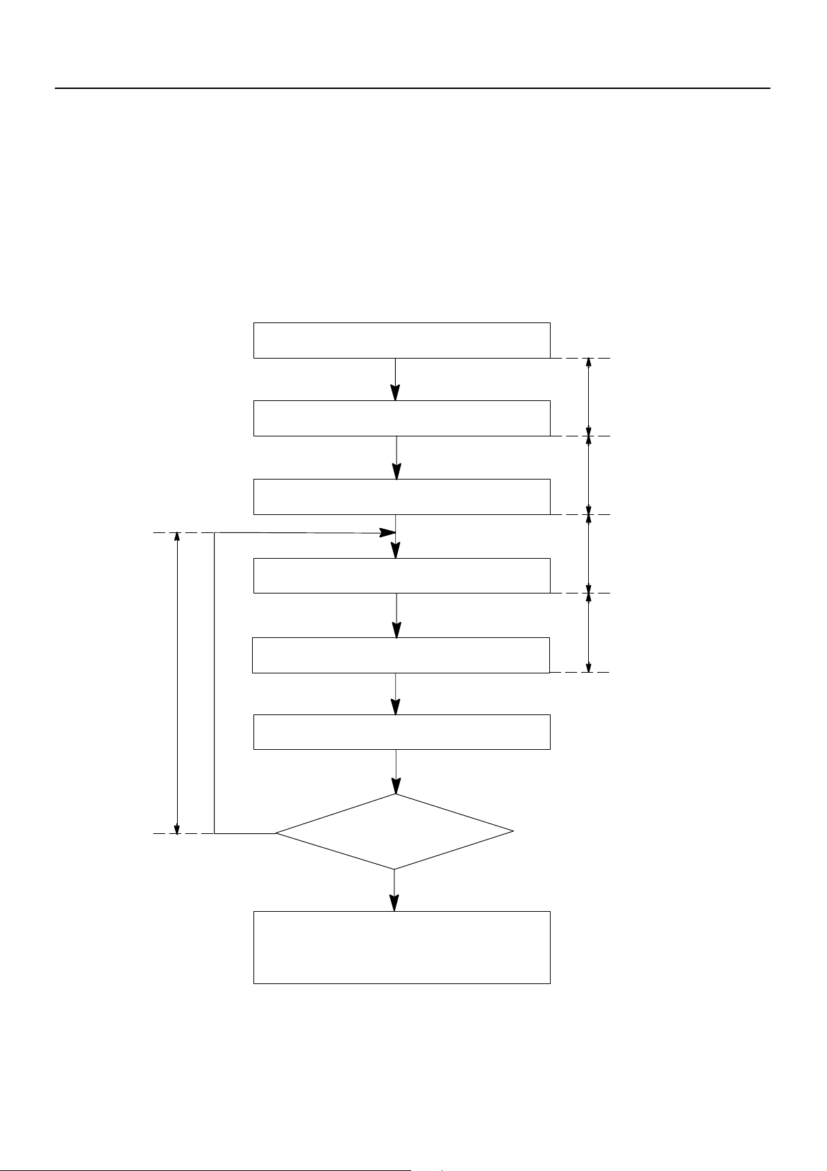
REGISTRATION PROCEDURE
1. KEY REGISTRATION IN AUTOMATIC REGISTRATION MODE
(a) Registration of a new transponder key.
HINT:
! This must be done when you install a new ECM.
! The new ECM is on the automatic key code registration mode. The already fixed number of key codes
for this ECM can be registered.
On this type of vehicle, up to 4 key codes can be registered.
! In the automatic registration mode, the last key registered becomes sub–key.
START
Insert the key in the key cylinder.
Under registration
Registration completion
Remove the key.
Security indicator blinks until the first
key is inserted. The indicator lights up
after the key registration.
Security Indicator ON
Security Indicator
OFF
Yes
2000 LEXUS LS400 (RM717U)
Will you register the
next key?
No
END
Security Indicator ON
(After the last key (sub–key)
has been registered, the indicator goes off.)
2107Author!: Date!:
Page 8
BE–245
–BODY ELECTRICAL ENGINE IMMOBILISER SYSTEM
HINT:
! When a key is not inserted in the key cylinder on the automatic registration mode, the security indicator
always lights on.
! When the immobiliser system operates normally and the key is pull out, the security indicator blinks.
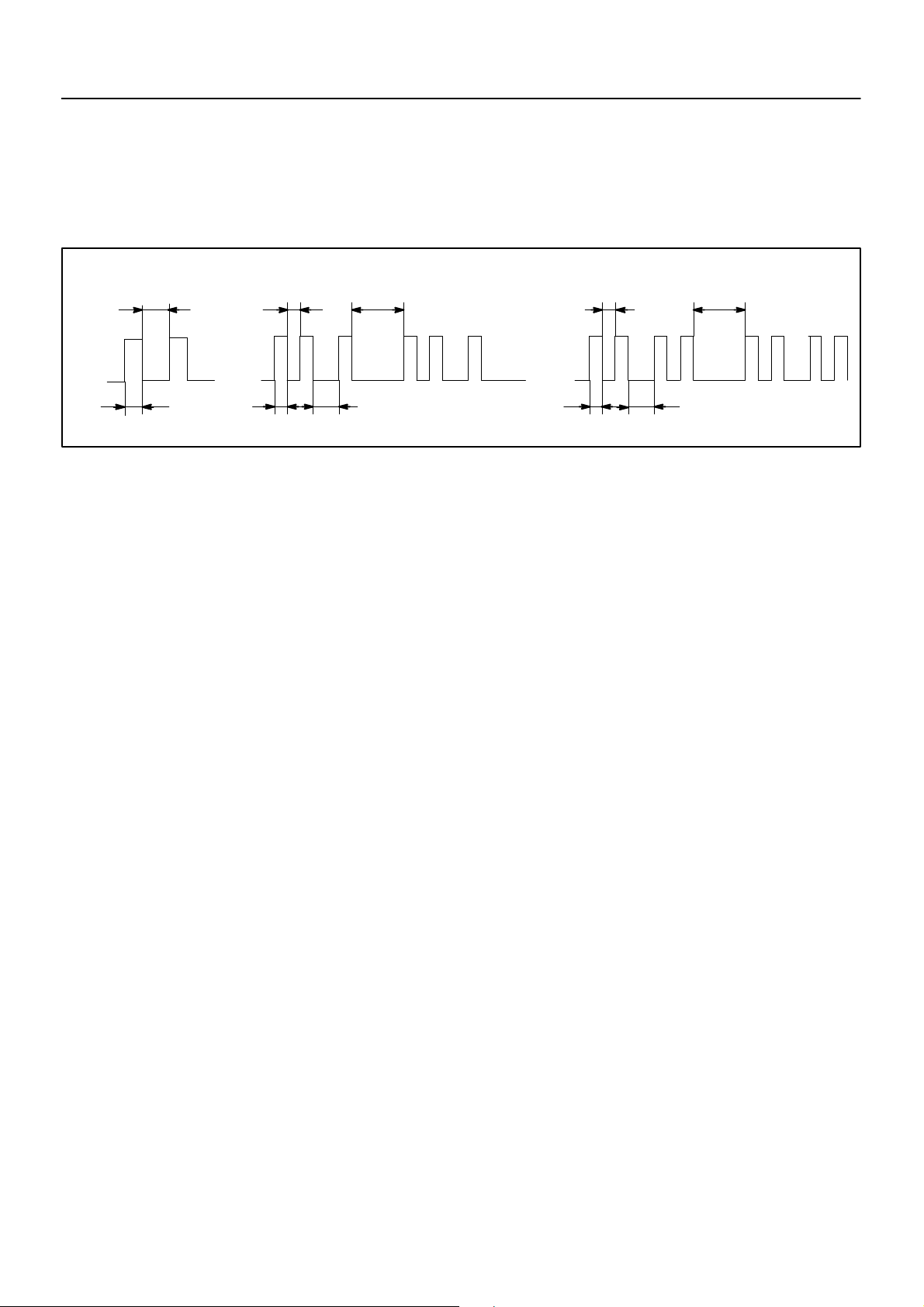
! When key code registration could not be performed on the automatic registration mode, code 2–1 is
output from the security indicator and when inserting the already registered key, code 2–2 is output.
Blinks
1.2 Sec.
0.8 Sec.
0.25 Sec.
0.25 Sec. 0.5 Sec.
Code 2–1 Code2–2
1 Sec.
0.25 Sec.
0.25 Sec.0.5 Sec.
1 Sec.
(b) Automatic registration mode completion
If completing the mode forcibly when more than 1 key code have been registered on the automatic
registration mode, perform the following procedures.
After 1 more key code have been registered with master key, perform step (1) or (2) without pulling
the key out or inserting the already registered key.
(1) Depress and release brake pedal 5 times or more within 15 sec.
(2) With the LEXUS hand–held tester, require automatic registration mode completion.
2000 LEXUS LS400 (RM717U)
2108Author!: Date!:
Page 9
BE–246
–BODY ELECTRICAL ENGINE IMMOBILISER SYSTEM
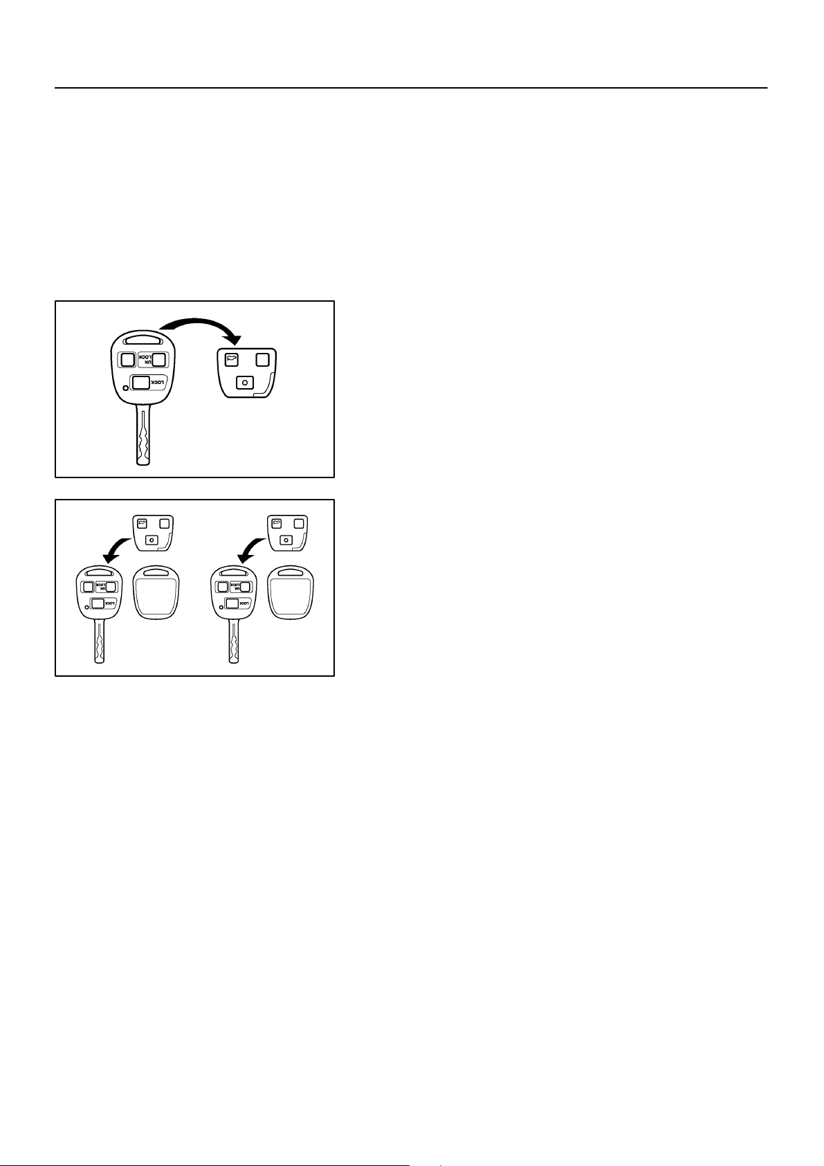
2. KEY REGISTRATION OF PROCEDURE NEW MASTER KEY AND NEW SUB–KEY ON THIS IS DESCRIBED BELOW
HINT:
Key registration of new master key and new sub–key on this vehicle when new ignition cylinder and key set,
and new lock cylinder set including ignition key cylinder are installed.
(a) Removing wire–less and immobiliser module from origi-
nal master key.
I04311
I04312
(b) Masking new master key.
After replacing and installing new ignition cylinder, install
removed original modules into new 2 key housing as supply parts.
(c) Registration of supplied new sub–key and /or master key
Register supplied new sub–key and /or master key by using new master key.
(See step 3 and 4)
NOTICE:
In case of replacing with ignition cylinder and key set, door
locks cannot be opened by new ignition keys. Therefore, to
avoid any trouble caused by empty battery of transmitter
of new ignition key, please bring the original key while driving.
2000 LEXUS LS400 (RM717U)
2109Author!: Date!:
Page 10

BE–247
–BODY ELECTRICAL ENGINE IMMOBILISER SYSTEM
3. REGISTRATION OF ADDITIONAL MASTER KEY
There are 2 ways for registration of additional master key, one way is depressing brake pedal and acceleration pedal and the other way is using LEXUS hand–held tester.
HINT:
! It is possible to register up to 7 master key codes including the already registered key code.
! When any operation time described below is over, registration mode completes.
! When the next procedure is performed while the timer is working, the timer completes counting time,
then next timer starts.
! When replacing ”Ignition Cylinder Key Set” or ”Lock Cylinder Set” and register according to the follow-
ing procedure using the original master key. However, after the registration of the additional master
key, as the original master key and the original sub–key is not necessary any more, so erase registration of those key codes.
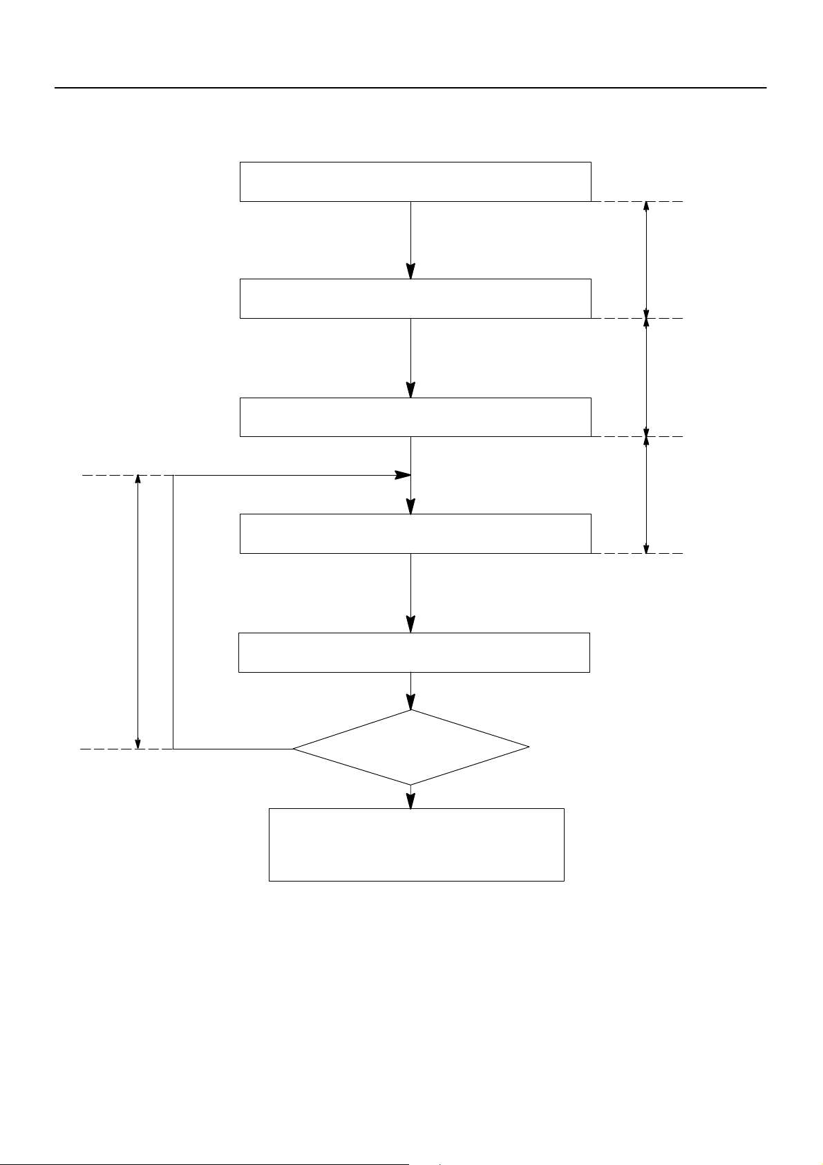
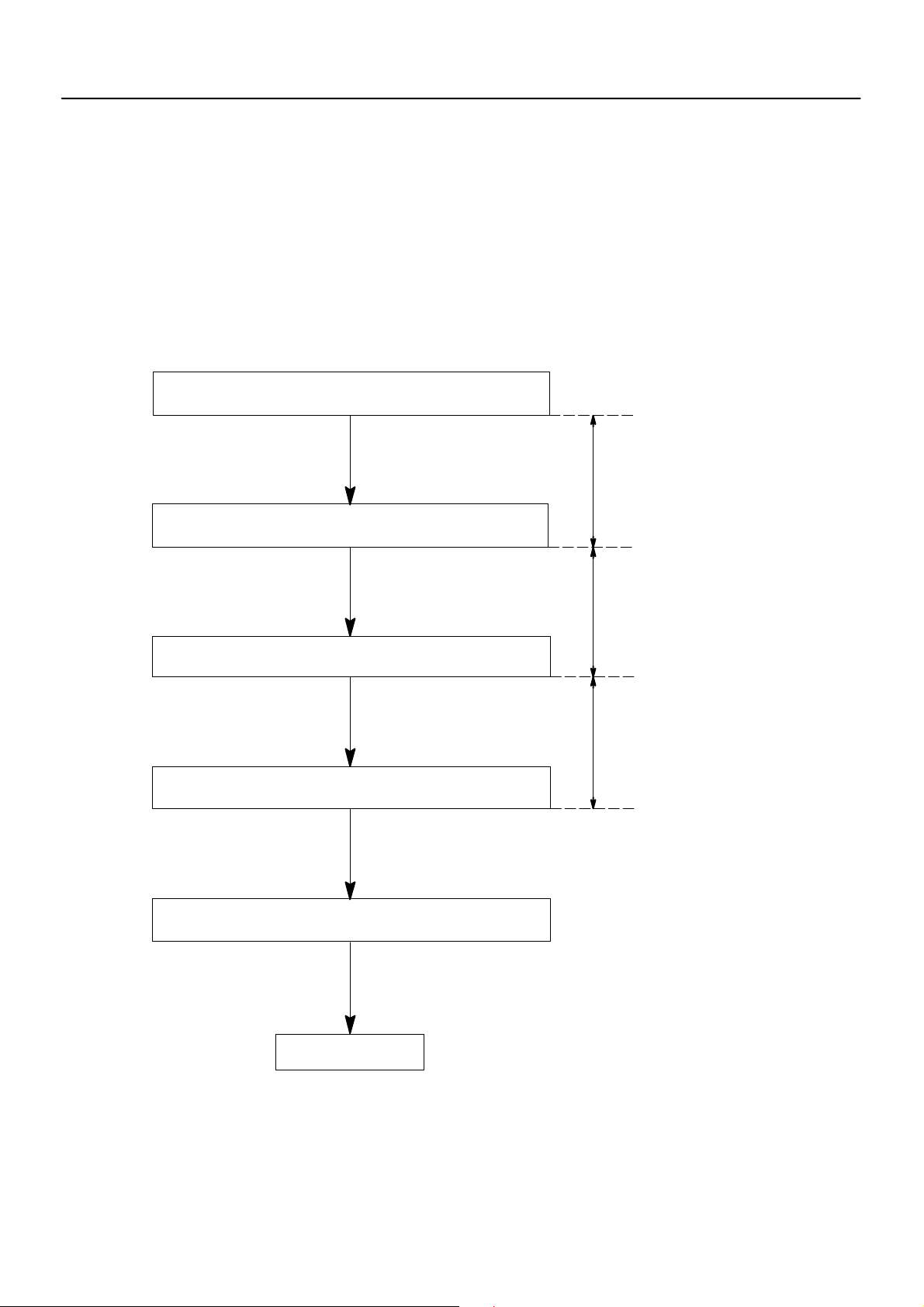
(1) Depressing brake pedal and acceleration pedal:
Insert already registered master key in the key
cylinder
Within 10 sec.
Depress and release the acceleration pedal 5
times.
Depress and release the brake pedal 6 times,
and remove the master key.
Insert key to be registered in key cylinder.
Depress and release the acceleration pedal 1
time. (Security indicator blinks)
After 60 sec. additional master key is registered.
(Security indicator is OFF)
Within 15 sec.
Within 20 sec.
Within 10 sec.
Within 10 sec.
2000 LEXUS LS400 (RM717U)
Yes
The registration mode completes when pulling
out the key and depressing and releasing the
brake pedal once or more within 10 secs. after
indicator has been off or 10 sec. have passed.
Will you register the
next key?
No
2110Author!: Date!:
Page 11
BE–248
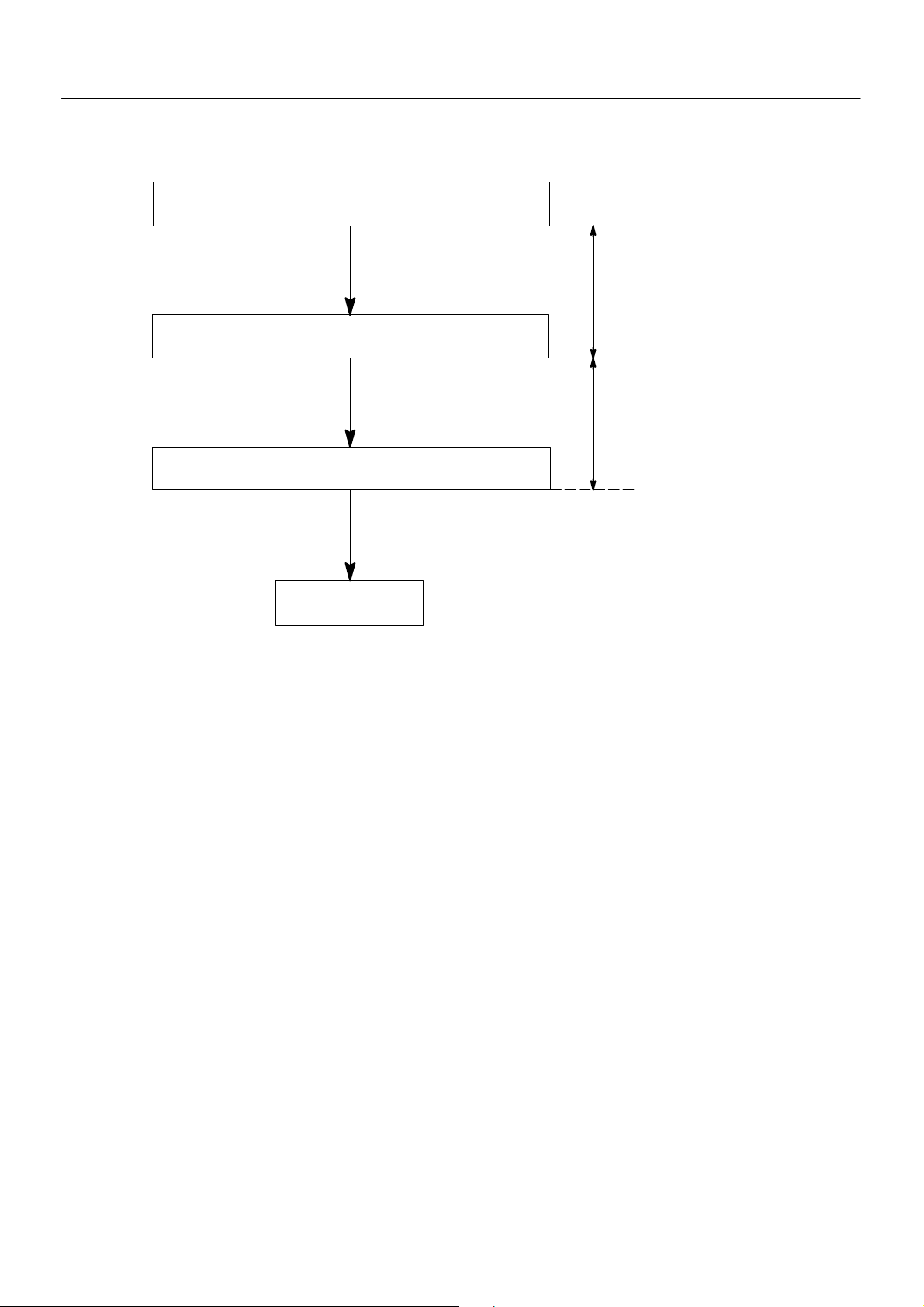
(2) Using LEXUS hand–held tester:
Insert already registered master key in the key cylinder.
Using LEXUS hand–held tester select master key registration.
Remove the master key.
–BODY ELECTRICAL ENGINE IMMOBILISER SYSTEM
Within 120 sec.
Within 20 sec.
Within
10 sec.
Within 10 sec.
Insert key to be registered in key cylinder.
(Security indicator blinks)
After 60 sec., additional master key is registered.
(Security indicator OFF)
Yes
Will you register the
next key?
No
The registration mode completes when pulling
out the key and depressing and releasing the
brake pedal once or more within 10 sec. after indicator has been off or 10 sec. have passed.
2000 LEXUS LS400 (RM717U)
2111Author!: Date!:
Page 12
BE–249
–BODY ELECTRICAL ENGINE IMMOBILISER SYSTEM
4. REGISTRATION OF ADDITIONAL SUB–KEY
There are 2 ways for registration of additional sub–key, one way is depressing brake pedal and acceleration
pedal and the other way is using LEXUS hand–held tester.
HINT:
! It is possible to register up to 3 sub–key codes including the already registered key code.
! When any operation time described below is over, registration mode completes.
! When the next procedure is performed while the timer is working, the timer completes counting time,
then next timer starts.
(1) Depressing brake pedal and acceleration pedal:
Insert already registered master key in the key
cylinder
Within 10 sec.
Depress and release the acceleration pedal 4
times.
Depress and release the brake pedal 5 times,
and remove the master key.
Insert key to be registered in key cylinder.
Depress and release the acceleration pedal 1
time. (Security indicator blinks)
After 60 sec. additional sub–key is registered.
(Security indicator is OFF)
Within 15 sec.
Within 20 sec.
Within 10 sec.
Within 10 sec.
2000 LEXUS LS400 (RM717U)
Yes
The registration mode completes when pulling
out the key and depressing and releasing the
brake pedal once or more within 10 sec. after indicator has been off or 10 sec. have passed.
Will you register the
next key?
No
2112Author!: Date!:
Page 13

BE–250
(2) Using LEXUS hand–held tester:
Insert already registered master key in the key cylinder.
Using LEXUS hand–held tester select sub–key registration.
Remove the master key.
–BODY ELECTRICAL ENGINE IMMOBILISER SYSTEM
Within 120 sec.
Within 20 sec.
Within
10 sec.
Within 10 sec.
Insert key to be registered in key cylinder.
(Security indicator blinks)
After 60 sec., additional master key is registered.
(Security indicator OFF)
Yes
Will you register the
next key?
No
The registration mode completes when pulling
out the key and depressing and releasing the
brake pedal once or more within 10 sec. after indicator has been off or 10 sec. have passed.
2000 LEXUS LS400 (RM717U)
2113Author!: Date!:
Page 14
BE–251
–BODY ELECTRICAL ENGINE IMMOBILISER SYSTEM
5. ERASURE OF TRANSPONDER KEY CODE
There are 2 ways for erasure of transponder key code, one way is depressing brake pedal and acceleration
pedal and the other way is using LEXUS hand–held tester.
NOTICE:
Delete all other master and sub–key codes leaving the master key code to use the operation. When
using the key which was used before deletion, it is necessary to register the code again.
HINT:
! When any operation time described below is over, registration mode completes.
! When the next procedure is performed while the timer is working, the timer completes counting time,
then next timer starts.
(1) Depressing brake pedal and acceleration pedal:
1. Insert master key in the key cylinder.
Within 15 sec.
2. Depress and release the acceleration pedal 6 times.
3. Depress and release the brake pedal 7 times.
4. Remove the master key.
5. Leave the vehicle more than 20 sec. without any
operation.
Within 20 sec.
Within 10 sec.
HINT:
If the key cannot be pulled out within 30 sec. from the first brake
depression in the step 3, the key code deletion is canceled.
2000 LEXUS LS400 (RM717U)
END
(Key code erased)
2114Author!: Date!:
Page 15
BE–252
(2) Using LEXUS hand–held tester:
1. Insert master key in the key cylinder.
2. Require key code deletion from hand–held tester.
(Security indicator blinks)
3. Remove the master key.
–BODY ELECTRICAL ENGINE IMMOBILISER SYSTEM
Within 120 sec.
Within 10 sec.
END
(Key code erased)
HINT:
When the key cannot be pulled out in the step 3, key code deletion is canceled.
(Security indicator is OFF.)
2000 LEXUS LS400 (RM717U)
2115Author!: Date!:
Page 16

–
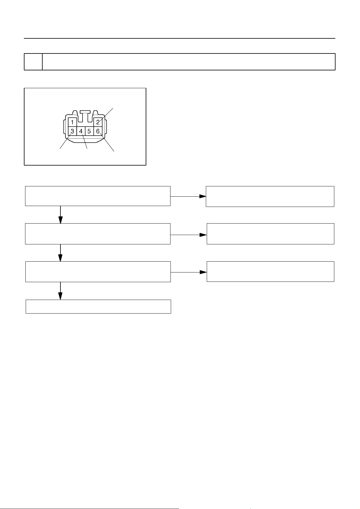
INSTALLATION
1. INSTALL GARAGE DOOR OPENER
(a) Connect the wire harness to the terminal 4 and 5.
(b) Install the 3 screws.
2. INSTALL FRONT PERSONAL LIGHT
(a) Connect the 2 connectors.
(b) Install the 3 screws.
3. INSTALL FRONT PERSONAL LIGHT LENS
BE–243
BE0D6–01
2106Author!: Date!:
Page 17
I03241
I03242
BE–241
–BODY ELECTRICAL GARAGE DOOR OPENER SYSTEM
BE0D5–01
INSPECTION
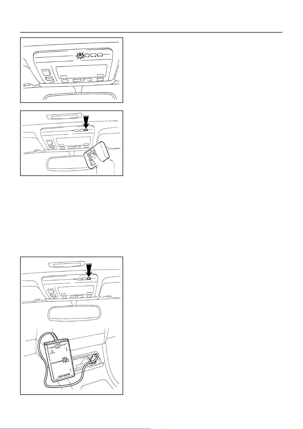
1. INSPECT GARAGE DOOR OPENER
Press the switch and check that each LED (red) lights up.
Even if only one switch is found not to light up, replace it.
2. INSPECT GARAGE DOOR OPENER REGISTRATION
AND TRANSMITTING
HINT:
Use the home link tester made by KENT MORE for this test.
As it is necessary to record the code of the hand held transmitter, customer’s code will be erased. When the inspection completes, please register the customer’s again.
(a) Check that the code of hand held transmitter for inspec-
tion can be recorded.
(See page
If the code can not be registered, replace garage door opener.
2000 LEXUS LS400 (RM717U)
(b) Press the switch which an inspection code has been reg-
istered for and check that LED (green) of the home link
tester lights up.
If the LED (green) does not light up, replace the garage door
opener.
I03244
2104Author!: Date!:
Page 18
BE–242
–BODY ELECTRICAL GARAGE DOOR OPENER SYSTEM
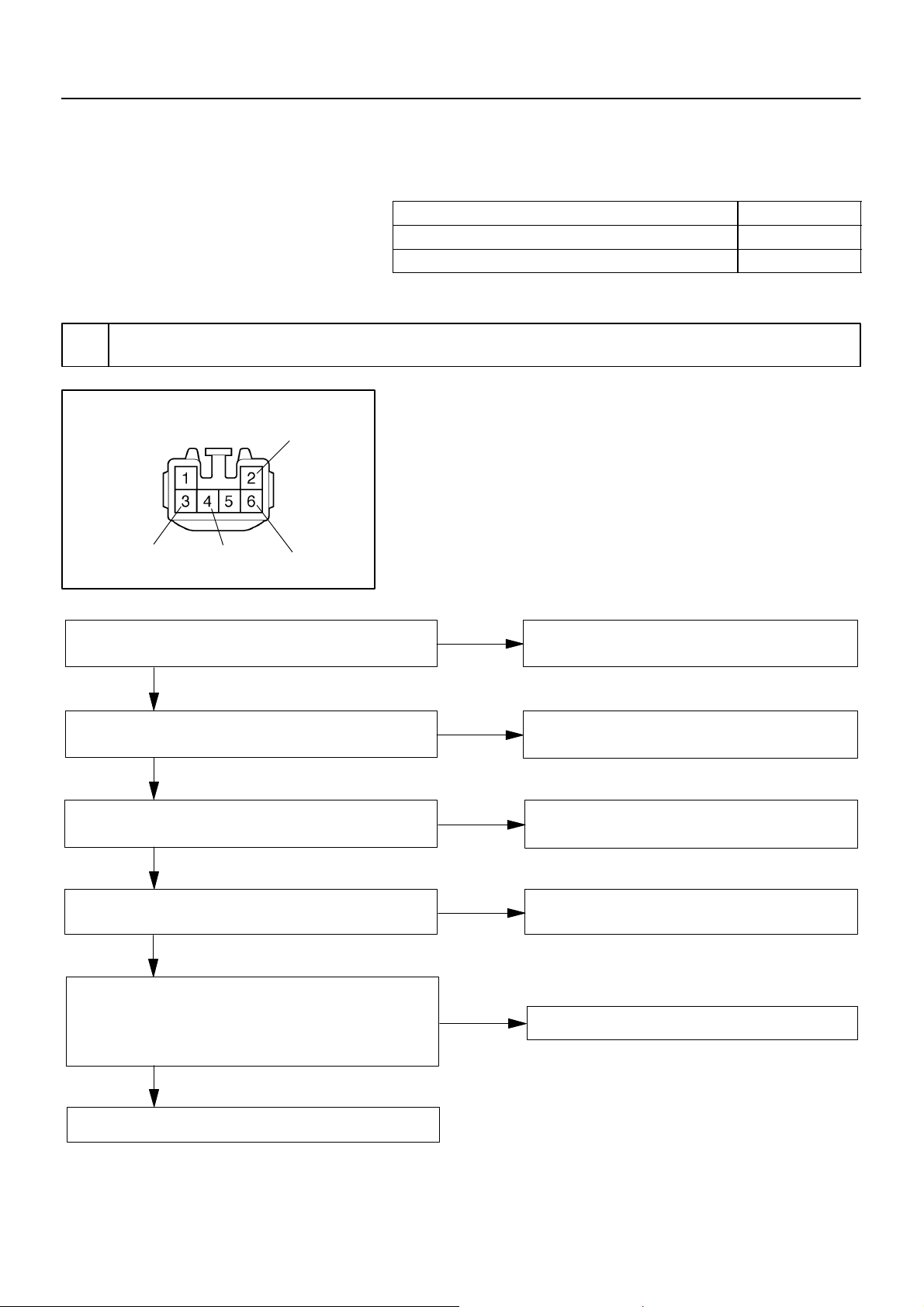
Wire Harness Side
3. INSPECT GARAGE DOOR OPENER CIRCUIT
Disconnect the connector from the switch and inspect the connector on the wire harness side, as shown.
I03432
Te s te r c o nn e c t i on Condition Specified condition
5 – Ground Constant Continuity
4 – Ground Constant Battery positive voltage
2000 LEXUS LS400 (RM717U)
2105Author!: Date!:
Page 19
BE–240
I03419
–
BE0D4–01
REMOVAL
1. REMOVE FRONT PERSONAL LIGHT LENS
2. REMOVE FRONT PERSONAL LIGHT
(a) Remove the 3 screws.
(b) Disconnect the 2 connectors.
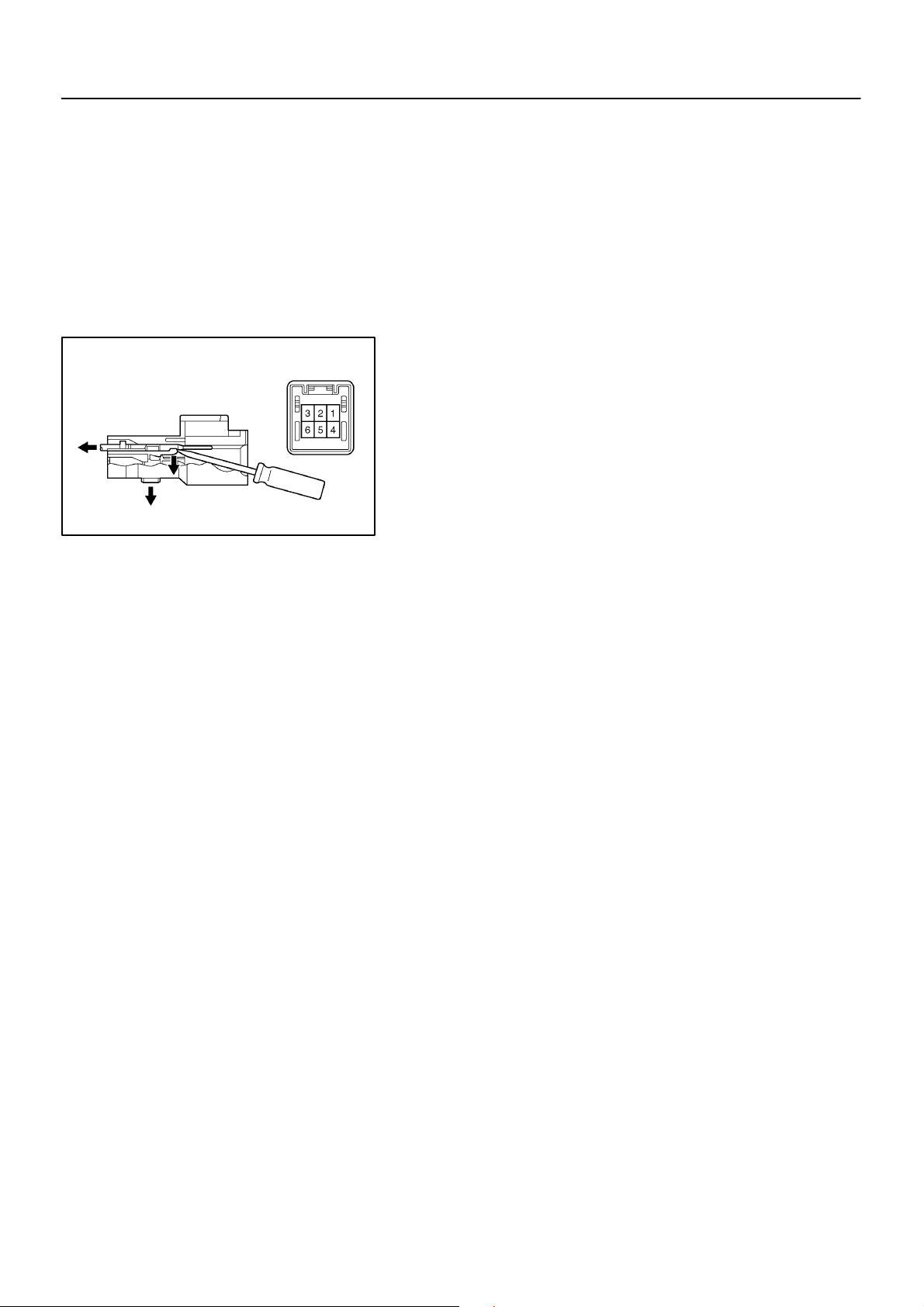
3. REMOVE GARAGE DOOR OPENER
(a) Remove the 3 screws.
(b) Remove the garage door opener connector from the per-
sonal light.
(c) Disconnect the secondary locking device.
(d) Release the locking plug of the terminal 4 and 5, and pull
the terminals out from the rear.
HINT:
Use a small screw driver.
2103Author!: Date!:
Page 20
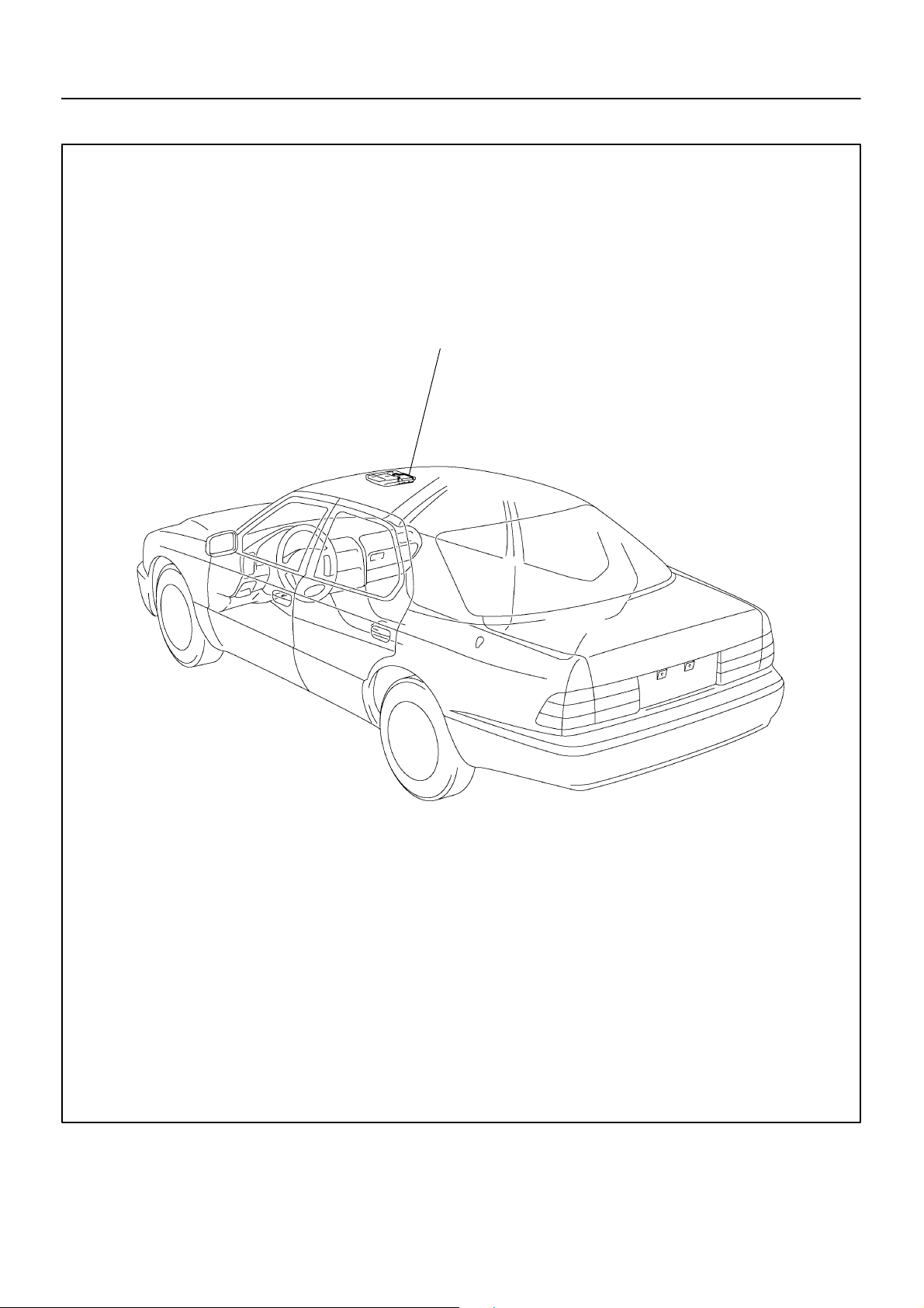
LOCATION
BE–239
–
BE0D3–01
Garage Door Opener
I03403
2102Author!: Date!:
Page 21
BE–236
–BODY ELECTRICAL GARAGE DOOR OPENER SYSTEM
GARAGE DOOR OPENER SYSTEM
BE0D2–01
REGISTRATION PROCEDURE
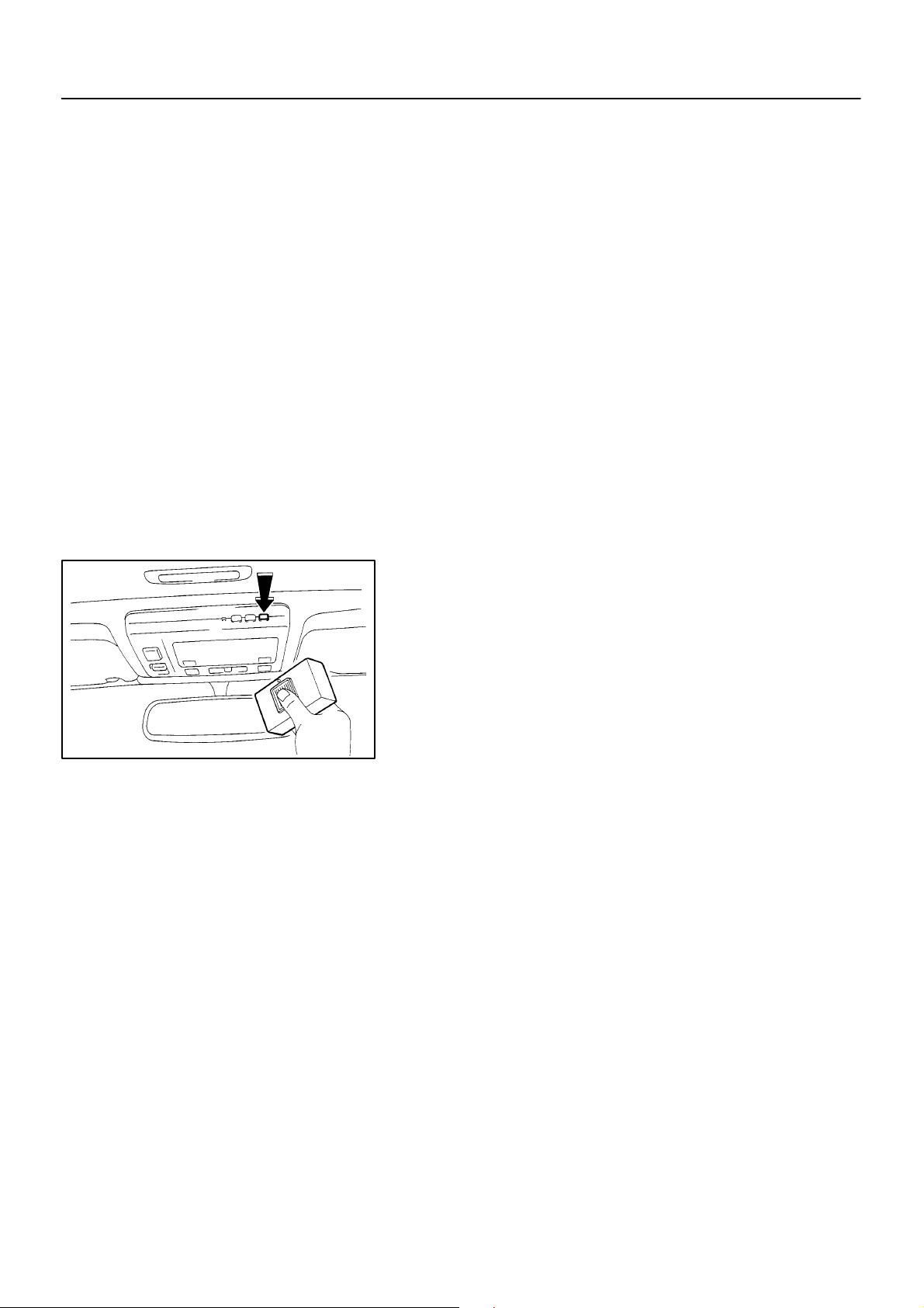
1. NEW CODE REGISTRATION
NOTICE:
! If pressing the switch of the original transmitter to
register the code, the system might operate.
! When registering the transmitter codes such as for
garage or gate, check that there is nobody around
those places then register.
(a) Press the switch for the item to be registered for 20 se-
conds
HINT:
When transferring to registration mode, LED (red) blinks in 1 Hz
cycle.
(b) In the condition of (a), bring the original transmitter to with-
in 1–inch area around the garage door opener and press
the switch. (code transmitting).
HINT:
When code registration completes correctly, LED (red) blinks in
5.6 Hz cycle.
I03243
2000 LEXUS LS400 (RM717U)
2099Author!: Date!:
Page 22
–BODY ELECTRICAL GARAGE DOOR OPENER SYSTEM
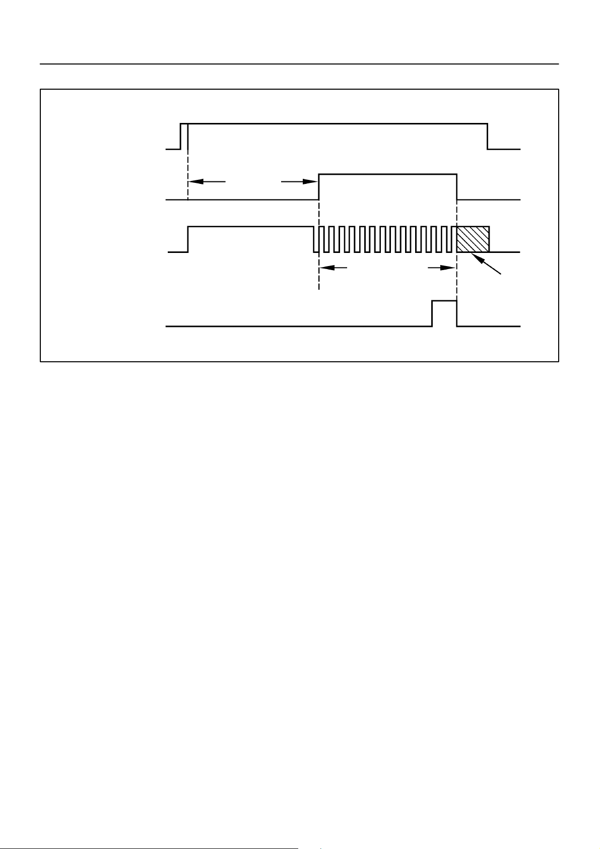
New code registration timing chart
BE–237
GARAGE DOOR
OPENER SWITCH
LEARN MODE
LED
OPERATION
ORIGINAL
TRANSMITTER
PRESSED
RELEASE
ENTER
EXIT
ON
OFF
ON
OFF
20 sec
LED flashes
at a rate of 1 Hz
LED flashes at a
rate of 5.6 Hz
I03487
If a code can not be registered, observe the following conditions.
HINT:
! If the battery of original transmitter is consumed.
! Press the switch of the transmitter repeatedly in registra-
tion mode, as some transmitters stop transmitting for 1 to
2 seconds.
! This system is not applicable to the garage door opener
which had been made before 1982.
2. CODE DELETION
(a) Press the switches at both ends of garage door opener
simultaneously for 20 seconds.
HINT:
When transferring to deletion mode, LED (red) blinks in 6 Hz
cycle.
(b) When releasing the switch within 10 seconds after trans-
ferring to deletion mode, all the registered codes will be
erased.
HINT:
Press the switch until blinking in 6 Hz cycle stops, so that the
default code for check is set.
2000 LEXUS LS400 (RM717U)
2100Author!: Date!:
Page 23
BE–238
–BODY ELECTRICAL GARAGE DOOR OPENER SYSTEM
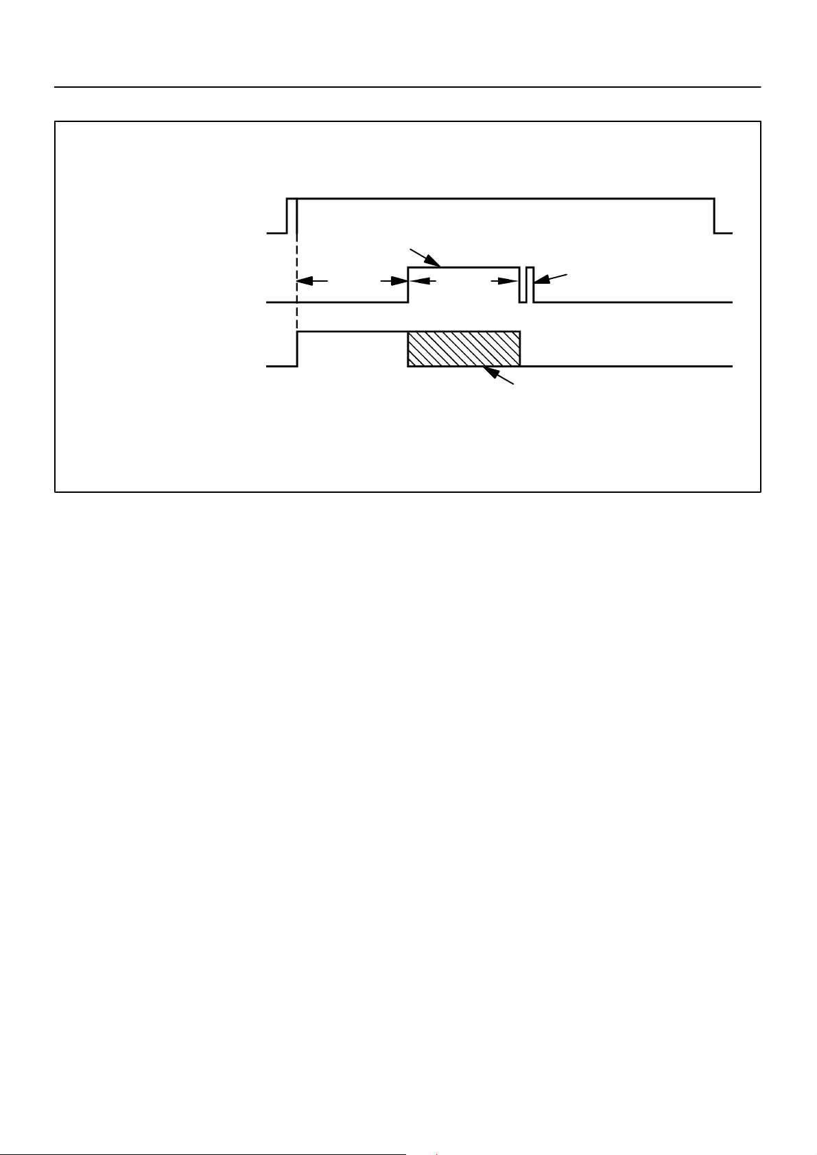
Code deletion timing chart
GARAGE DOOR
OPENER SWITCH
(Switch at both end)
CLEAR/DEFAULT
MODE
LED
OPERATION
PRESSED
RELEASE
ON
OFF
ON
OFF
Enter erase mode to erase all 3 channels
20 SEC
10 SEC
LED flashes at a rate of 6 HZ
LOAD DEFAULT
I03488
2000 LEXUS LS400 (RM717U)
2101Author!: Date!:
Page 24
BE–234
–BODY ELECTRICAL CLOCK
1. PROBLEM No.1
1 CLOCK WILL NOT OPERATE
+B
e–6–1
GND
ACC
IG
I03486
CLOCK
BE0D1–02
TROUBLESHOOTING
HINT:
Problem No.
Clock will not operate 1
Clock loses or gains time 2
± 1.5 seconds / da
(a) Turn the ignition switch ON.
(b) Check that the battery positive voltage is 10 – 16 V.
If voltage is not as specified, replace the battery.
(c) Check that the DOME FR, GAUGE and FR CIG fuses in
not below.
If the fuse is blown, replace the fuse and check for short.
(d) Troubleshoot the clock as follows.
HINT:
Inspect the connector on the wire harness side.
Is there battery positive voltage between terminal
+B and body ground?
Yes
Is there battery positive voltage between terminal
IG and body ground?
Yes
Is there battery positive voltage between terminal
ACC and body ground?
Yes
Is there continuity battery terminal GND and body
ground?
Yes
Is there battery positive voltage between terminal
ILL and body ground when rheostat knob is turned
to any position except fully clockwise? (Taillight
switch ON)
Yes
No
No
No
No
No
Open or short circuit in wire harness between
terminal +B and DOME fuse.
Open or short circuit in wire harness between
terminal IG and GAUGE fuse.
Open or short circuit in wire harness between
terminal ACC and FR CIG fuse.
Open circuit in wire harness between terminal
GND and body ground.
Rheostat light control or wire harness faulty.
Replace clock assembly.
2000 LEXUS LS400 (RM717U)
2097Author!: Date!:
Page 25
2. PROBLEM No.2
2 CLOCK LOSES OR GAINS TIME
IG
+B
e–6–1
GND
ACC
I03486
BE–235
–BODY ELECTRICAL CLOCK
(a) Check that the battery positive voltage is 10 – 16 V.
If voltage is not as specified, replace the battery.
(b) Inspect the error of the clock.
Allowable error (per day): ± 2.0 seconds
If the error exceeds the allowable error, replace the clock assembly.
(c) Check if the clock adjusting button is sticking in position
and has failed to return.
(d) Troubleshoot the clock as follows.
HINT:
Inspect the connector on the wire harness side.
Is there 10 – 16 V between terminal +B and body
ground?
Yes
Is there 10 – 16 V between terminal IG and body
ground?
Yes
Is there 10 – 16 V between terminal ACC and body
ground?
Yes
Adjust or replace clock assembly.
Bellow 10 V
Bellow 10 V
Bellow 10 V
Locate cause and repair, or recharge battery.
Locate cause and repair, or recharge battery.
Locate cause and repair, or recharge battery.
2000 LEXUS LS400 (RM717U)
2098Author!: Date!:
Page 26
Antenna Nut
Twist
BE4671
BE5781
BE5780
BE4674
BE–233
–
BE11Z–01
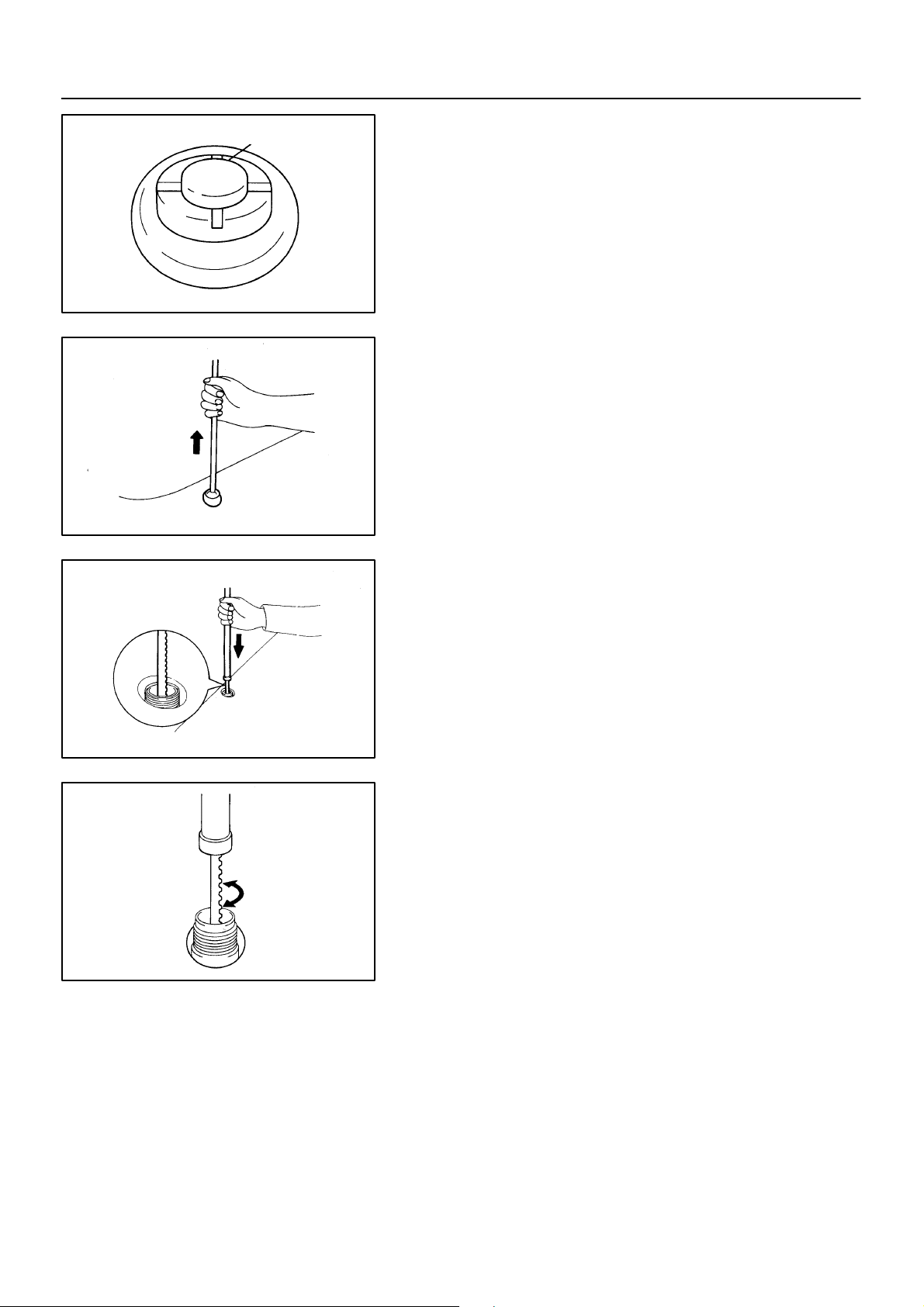
REPLACEMENT
1. Auto Antenna Models:
REMOVE ANTENNA ROD
HINT:
Do this operation with the battery negative (–) cable connected
to the battery terminal.
(a) Turn the ignition switch to ”LOCK” position.
(b) Remove the antenna nut.
(c) Press the ”AM, FM” buttons on the radio receiver, and si-
multaneously turn the ignition switch to ”ACC” position.
HINT:
! The rod will extend fully and be released form the motor
antenna.
! After removing the antenna rod, leave the ignition switch
as ”ACC”.
NOTICE:
To prevent body damage when the antenna rod is released,
hold the rod while it comes out.
2. IAuto Antenna Models:
NSTALL ANTENNA ROD
(a) Insert the cable of the rod until it reaches the bottom.
HINT:
! When inserting the cable, the teeth on the cable must face
toward the rear of the vehicle.
! Insert the antenna approx. 300 mm (11.8 in.).
(b) Wind the cable to retract the rod by turning the ignition
switch to ”LOCK” position.
HINT:
! If the ignition switch is already in ”LOCK” position, do step
1 (c) first, then turn the ignition switch to ”ACC” position.
! In case the cable is not wound, twist it, as shown in the
illustration.
! Even if the rod has not retracted fully, install the antenna
nut and inspect the antenna rod operation. It will finally retract fully.
(c) Inspect the antenna rod operation by pushing the radio
wave band select buttons.
2096Author!: Date!:
Page 27
BE–232
–
BE11Y–01
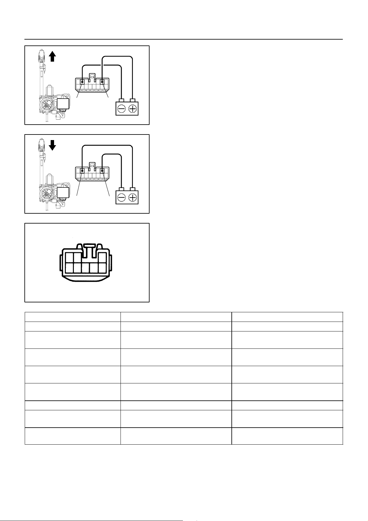
INSPECTION
1. Auto Antenna Models:
INSPECT ANTENNA MOTOR
(a) Connect the positive (+) lead from the battery to terminal
2 and the negative (–) lead to terminal 5.
(b) Check that the motor turns (moves upward).
25
I05587
25
I05580
NOTICE:
These tests must be done quickly (within 3 – 5 seconds) to
prevent the coil from burning out.
(c) Then, reverse the polarity, check that the motor turns the
opposite way (moves downward).
NOTICE:
These tests must be done quickly (within 3 – 5 seconds) to
prevent the coil from burning out.
Wire Harness Side
213
45 768
Te s te r c o nn e c t i on Condition Specified condition
7 – Ground Constant Continuity
1 – Ground
1 – Ground
2 – Ground
2 – Ground
3 – Ground Constant Battery voltage
5 – Ground
5 – Ground
2. Auto Antenna Models:
INSPECT ANTENNA MOTOR CONTROL RELAY CIRCUIT
Disconnect the connector from the relay and inspect the connector on wire harness side, as shown in the chart below.
Z08688
Ignition switch ACC or ON,
and radio switch ON and Others
Ignition switch ACC or ON,
and radio switch ON and AM
Ignition switch ACC or ON,
and radio or tape or CD switch OFF
Ignition switch ACC or ON,
and radio or tape or CD switch ON
Ignition switch ACC or ON,
and radio switch OFF
Ignition switch ACC or ON,
and radio switch ON
No voltage
Battery voltage
No voltage
Battery voltage
No voltage
Battery voltage
2095Author!: Date!:
Page 28
ANTENNA
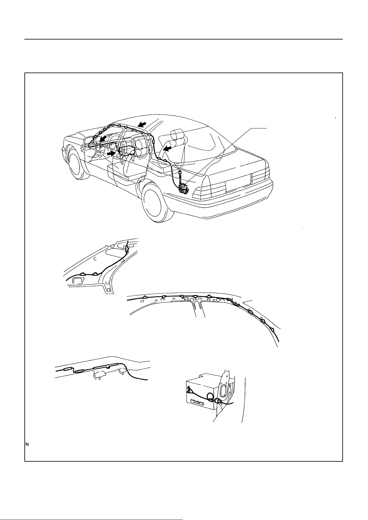
LOCATION
BE–231
–
BE11X–01
B
View ”A”
C
A
D
View ”B”
Antenna
View ”C”
View ”D”
I10507
2094Author!: Date!:
Page 29
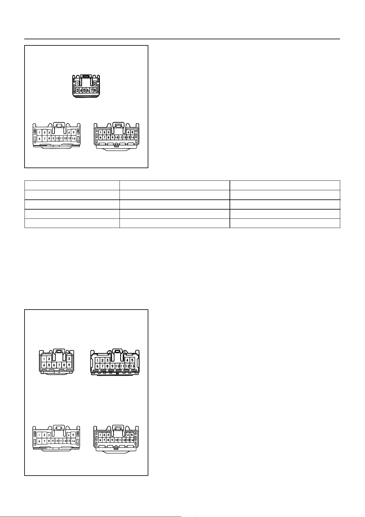
BE–226
Wire Harness Side
Connector ”A”
Connector ”B” Connector ”C”
Te s te r c o nn e c t i on Condition Specified condition
B14 – Ground Constant Continuity
B6 – Ground Ignition switch position ACC or ON Battery positive voltage
B6 – Ground Ignition switch position LOCK No voltage
B1 – Ground Constant Battery positive voltage
–BODY ELECTRICAL AUDIO SYSTEM
BE0D0–01
INSPECTION
1. Nakamichi made:
INSPECT RADIO RECEIVER ASSEMBLY CIRCUIT
Disconnect the connectors from the radio receiver assembly.
And inspect the connector on the wire harness side, as shown.
Z14756
If circuit is not as specified, inspect the circuits connected to other parts.
HINT:
Check the wire harness between radio receiver assembly and
the CD auto changer, between radio receiver assembly and
power amplifier.
Wire Harness Side
Connector ”A” Connector ”B”
Connector ”C”
e–9–1 e–13–1–A
eh–14–1 h–14–1–A
2000 LEXUS LS400 (RM717U)
Connector ”D”
2. Nakamichi made:
INSPECT POWER AMPLIFIER CIRCUIT
Disconnect the connector from the power amplifier and inspect
the connector on the wire harness side, as shown.
Z14757
2089Author!: Date!:
Page 30
–BODY ELECTRICAL AUDIO SYSTEM
Te s te r c o nn e c t i on Condition Specified condition
A4 – Ground Constant Continuity
A5 – Ground Constant Battery positive voltage
A6 – Ground Ignition switch position ACC or ON Battery positive voltage
D6 – Ground
Ignition switch position ACC or ON
Radio, Tape or CD switch ON
Battery positive voltage
If circuit is not as specified, inspect the circuits connected to other parts.
BE–227
Wire Harness Side
h–14–1–A
Te s te r c on n e c t i on t o
terminal number
5 – Ground Constant Battery positive voltage
4 – Ground Ignition switch LOCK No voltage
4 – Ground Ignition switch ACC or ON Battery positive voltage
3. Nakamichi made:
INSPECT CD AUTO CHANGER CIRCUIT
Disconnect the connectors from the controller and inspect the
connector on the wire harness side, as shown.
Z14758
Condition Specified condition
If circuit is not as specified, inspect the circuits connected to other parts.
HINT:
Since the signals to and from the AP+, AP–, SGND, GND1 terminals are serial signals, they cannot ordinarily be measured
with a tester.
2000 LEXUS LS400 (RM717U)
2090Author!: Date!:
Page 31

BE–228
–BODY ELECTRICAL AUDIO SYSTEM
Wire Harness Side
Connector ”A”
Connector ”B”
Te s te r c o nn e c t i on Condition Specified condition
B1 – Ground Constant Continuity
A6 – Ground Ignition switch position ACC or ON Battery positive voltage
A6 – Ground Ignition switch position LOCK No voltage
A1 – Ground Constant Battery positive voltage
4. Pioneer made:
INSPECT RADIO RECEIVER ASSEMBLY CIRCUIT
Disconnect the connectors from the radio receiver assembly.
And inspect the connector on the wire harness side, as shown.
I03482
If circuit is not as specified, inspect the circuits connected to other parts.
HINT:
Check the wire harness between power amplifier and the CD
auto changer, between radio receiver assembly and power amplifier.
Wire Harness Side
Connector ”A”
Connector ”C”
Connector ”E”
2000 LEXUS LS400 (RM717U)
Connector ”B”
Connector ”D”
5. Pioneer made and LEXUS navigation system:
INSPECT POWER AMPLIFIER CIRCUIT
Disconnect the connector from the power amplifier and inspect
the connector on the wire harness side, as shown.
I03483
2091Author!: Date!:
Page 32

–BODY ELECTRICAL AUDIO SYSTEM
Te s te r c o nn e c t i on Condition Specified condition
B7 – Ground Constant Continuity
B4 – Ground Constant Battery positive voltage
C12 – Ground Ignition switch position ACC or ON Battery positive voltage
If circuit is not as specified, inspect the circuits connected to other parts.
BE–229
Wire Harness Side
Te s te r c on n e c t i on t o
terminal number
5 – Ground Constant Battery positive voltage
12 – Ground Ignition switch LOCK No voltage
12 – Ground Ignition switch ACC or ON Battery positive voltage
6. Pioneer made and LEXUS navigation system:
INSPECT CD AUTO CHANGER CIRCUIT
Disconnect the connectors from the controller and inspect the
connector on the wire harness side, as shown.
I03484
Condition Specified condition
If circuit is not as specified, inspect the circuits connected to other parts.
HINT:
Since the signals to and from the AP+, AP–, SGND, GND1 terminals are serial signals, they cannot ordinarily be measured
with a tester.
2000 LEXUS LS400 (RM717U)
2092Author!: Date!:
Page 33

BE–230
–BODY ELECTRICAL AUDIO SYSTEM
Wire Harness Side
Connector ”A”
Connector ”B” Connector ”C”
Te s te r c o nn e c t i on Condition Specified condition
B2 – Ground Constant Continuity
B1 – Ground Ignition switch position ACC or ON Battery positive voltage
B1 – Ground Ignition switch position LOCK No voltage
B4 – Ground Constant Battery positive voltage
7. LEXUS navigation system:
INSPECT RADIO RECEIVER ASSEMBLY CIRCUIT
Disconnect the connectors from the radio receiver assembly.
And inspect the connector on the wire harness side, as shown.
I03485
If circuit is not as specified, inspect the circuits connected to other parts.
HINT:
Check the wire harness between power amplifier and the CD
auto changer, between radio receiver assembly and power amplifier.
8. INSPECT GLASS PRINTED ANTENNA
(Use same procedure as for ”INSPECT DEFOGGER WIRES”
on page BE–116)
9. REPAIR GLASS PRINTED ANTENNA
(Use same procedure as for ”REPAIR DEFOGGER WIRES” on
page BE–116)
2000 LEXUS LS400 (RM717U)
2093Author!: Date!:
Page 34

LOCATION
BE–225
–
BE0CZ–01
Engine Room Junction Block
! DOME Fuse
! RADIO No.1 Fuse
Tweeter
Speaker
Ignition Switch
Tweeter Speaker
Instrument Panel
Junction Block
! RADIO No.2 Fuse
Power Amplifier
Front Door Speaker
Rear Door Speaker
CD Auto
Changer
Radio Receiver
Assembly
Front Door Speaker
Rear Door Speaker
Woofer Speaker
I03405
2088Author!: Date!:
Page 35

BE–207
–BODY ELECTRICAL AUDIO SYSTEM
BE0CY–01
TROUBLESHOOTING
NOTICE:
When replacing the internal mechanism (computer part) of the audio system, be careful that no part
of your body or clothing comes in contact with the terminals of the leads from the IC, etc. of the replacement part (spare part).
HINT:
This inspection procedure is a simple troubleshooting which should be carried out on the vehicle during system operation and was prepared on the assumption of system component troubles (except for the wires and
connectors, etc.).
Always inspect the trouble taking the following items into consideration.
! Open or short circuit of the wire harness
! Connector or terminal connection fault
Problem No.
Radio No power coming in. 1
Power coming in, but radio not operating. 2
Noise present, but AM – FM not operating. 3
Either speaker does not work. 4
Either AM or FM does not work. 5
Reception poor (Volume faint). 5
Few preset tuning bands. 5
Sound quality poor. 6
Cannot set station select button. 7
Preset memory disappears. 7
Ta p e P l a y er Cassette tape cannot be inserted. 8
Cassette tape inserts, but no power. 9
Power coming in, but tape player not operating. 10
Either speaker does not work. 11
Sound quality poor (Volume faint). 12
Ta p e j a m me d , m al f u n ct i o n wi t h ta p e s pe e d or a u to – r e v er s e . 13
Cassette tape will not eject. 14
CD Player CD cannot be inserted. 15
CD inserts, but no power. 16
Power coming in, but CD player not operating. 17
Sound jumps. 18
Sound quality poor (Volume faint). 19
Either speaker does not work. 20
CD will not eject. 21
Amplifier No power coming in. 22
Either speaker does not work. 23
Noise Noise produced by vibration or shock while driving. 24
Noise produced when engine starts. 25
Noise occurs 26
2000 LEXUS LS400 (RM717U)
2070Author!: Date!:
Page 36

BE–208
1
Radio NO POWER COMING IN
–BODY ELECTRICAL AUDIO SYSTEM
Is tape player operating normally?
Yes
Radio receiver assembly faulty.
No
No
Check if RADIO No.2 fuse is OK.
Replace fuse.
Yes
Is ACC applied to radio receiver assembly?
No
ACC wire harness faulty.
Yes
Check if DOME fuse is OK?
No
Replace fuse.
Yes
Is +B applied to radio receiver assembly?
No
+B wire harness faulty.
Yes
Check if GND (wire harness side) to radio is
No
GND faulty.
OK?
Yes
Radio receiver assembly faulty.
2 Radio POWER COMING IN, BUT RADIO NOT OPERATING
If radio side faulty
Is tape player operating normally?
Yes
Go to No. 23.
No
Is there continuity in speaker wire harness?
No
Speaker wire harness faulty.
Yes
Te mp or ar il y i ns ta ll a no the r sp ea ke r.
Function OK?
Yes
speaker faulty.
No
Radio receiver assembly faulty.
3 Radio NOISE PRESENT, BUT AM–FM NOT OPERATING
Go to No. 23
Radio receiver assembly faulty.
If radio side faulty
Radio receiver
assembly faulty.
V06272
2000 LEXUS LS400 (RM717U)
2071Author!: Date!:
Page 37

–BODY ELECTRICAL AUDIO SYSTEM
4 Radio EITHER SPEAKER DOES NOT WORK
BE–209
Is tape player operating normally?
No
Is hiss produced by non–functioning speaker?
No
Check if GND to power amplifier is OK?
Yes
Are +B and +B2 applied to power amplifier?
Yes
Is AMP applied to power amplifier?
Yes
Is there continuity in wire harness? (Radio receiver
to power amplifier)
Yes
Is there continuity in speaker wire harness?
Yes
Te mp or ar il y i ns ta ll a no the r sp ea ke r.
Functions OK?
Yes
Yes
No
No
No
No
No
Yes
Radio receiver assembly faulty.
Radio receiver assembly faulty.
GND fault.
+B and +B2 wire harness faulty.
Check the radio receiver assembly.
Wire harness faulty.
Speaker wire harness faulty.
Speaker faulty.
No
Radio receiver assembly faulty.
2000 LEXUS LS400 (RM717U)
V06273
2072Author!: Date!:
Page 38

BE–210
–BODY ELECTRICAL AUDIO SYSTEM
5 Radio
FEW PRESET TUNING BANDS
Problem with radio wave signals or location?
(See page BE–203)
No
Are both AM and FM defective?
Yes
Go to No.28
If radio side faulty
Is tape player operating normally?
No
Temporarily install another speaker. Functions
OK?
No
Radio receiver assembly faulty.
EITHER AM OR FM DOES NOT WORK, RECEPTION POOR (VOLUME FAINT),
Yes
No
Yes
Yes
Poor signals, poor location.
Radio receiver assembly faulty.
Radio receiver assembly faulty.
Speaker faulty.
6
Radio SOUND QUALITY POOR
Is sound quality always bad?
Yes
Is tape player operating normally?
No
Is speaker properly installed?
Yes
Temporarily install another speaker. Functions
OK?
6–A.
Is sound quality bad in certain areas only?
No
No
Yes
No
Yes
No
Yes
Go to step 6–A.
If radio side faulty
Go to No.28.
Radio receiver
assembly faulty.
Install properly.
Speaker faulty.
Radio receiver assembly faulty.
Poor signals, poor location.
Radio receiver assembly faulty.
2000 LEXUS LS400 (RM717U)
V03663
2073Author!: Date!:
Page 39

BE–211
–BODY ELECTRICAL AUDIO SYSTEM
7 Radio CANNOT SET STATION SELECT BUTTON, PRESET MEMORY DISAPPEARS
Can cassette tape be inserted in tape player?
Yes
Radio receiver assembly faulty.
No
No
Check if DOME and RADIO No.2 fuses are OK.
Replace fuse.
Yes
Are ACC and +B applied to radio receiver assem-
No
ACC and +B wire harness faulty.
bly?
Yes
Check if GND (wire harness side) to radio is OK.
No
GND faulty.
Yes
Radio receiver assembly faulty.
8 Tape Player CASSETTE TAPE CANNOT BE INSERTED
Is there a foreign object inside tape player? Remove foreign object.
Yes
No
Is auto search button of radio operating normally?
No
Check if DOME and RADIO No.2 fuses are OK.
Yes
Are ACC and +B applied to radio receiver assembly?
No
ACC and +B wire harness faulty.
Yes
No
Yes
Radio receiver assembly faulty.
Replace fuse.
Check if GND (wire harness side) to radio receiver
assembly is OK?
No Yes
GND faulty.
Radio receiver
assembly faulty.
2000 LEXUS LS400 (RM717U)
V06275
2074Author!: Date!:
Page 40

BE–212
–BODY ELECTRICAL AUDIO SYSTEM
9 CASSETTE TAPE INSERTS, BUT NO POWER
Tape Player
Is tape operating normally?
No
Check if DOME and RADIO No.2 fuses are OK.
Yes
Is ACC applied to radio receiver assembly?
No
ACC wire harness faulty.
10 POWER COMING IN, BUT TAPE PLAYER NOT OPERATINGTape Player
Functions OK if different cassette tape inserted?
No
Is radio operating normally?
Yes
No
Yes
Yes
Yes
Radio receiver assembly faulty.
Replace fuse.
Radio receiver assembly faulty.
Cassette tape faulty.
Radio receiver assembly faulty.
No
Is there continuity in speaker wire harness?
Yes
Te mp or ar il y i ns ta ll a no the r sp ea ke r.
Functions OK?
No
Radio receiver assembly faulty.
No
Yes
Speaker wire harness faulty.
Speaker faulty.
2000 LEXUS LS400 (RM717U)
V06276
2075Author!: Date!:
Page 41

–BODY ELECTRICAL AUDIO SYSTEM
BE–213
11
Tape Player
EITHER SPEAKER DOES NOT WORK
Check if RADIO No.1 and RADIO No.2 fuses are
OK.
Yes
Is radio operating normally?
No
Check if GND to power amplifier is OK.
Yes
Are +B and +B2 applied to power amplifier?
Yes
Is AMP applied to power amplifier?
Yes
Is there continuity in wire harness? (Radio receiver
to power amplifier)
Yes
Temporarily install another woofer speaker.
Functions OK?
No
Yes
No
No
No
No
Yes
Replace fuse.
Radio receiver assembly faulty.
GND faulty.
+B and +B2 wire harness faulty.
Check the radio receiver assembly.
Wire harness faulty.
Woofer speaker faulty.
No
Is there continuity in speaker wire harness?
Yes
Te mp or ar il y i ns ta ll a no the r po we r am pli fi er.
Functions OK?
Yes
Power amplifier faulty.
No
No
Speaker wire harness faulty.
Radio receiver assembly faulty.
2000 LEXUS LS400 (RM717U)
V06277
2076Author!: Date!:
Page 42

BE–214
–BODY ELECTRICAL AUDIO SYSTEM
Tape Player
SOUND QUALITY POOR (VOLUME FAINT)12
Functions OK if different cassette tape inserted?
No
Operates normally after cleaning the heads?
(See page BE–203)
No
Is radio operating normally?
No
Is speaker properly installed?
Yes
Te mp or ar il y i ns ta ll a no the r sp ea ke r.
Functions OK?
No
Radio receiver assembly faulty.
Yes
Yes
Yes
No
Yes
Cassette tape faulty.
Head dirty.
Radio receiver assembly faulty.
Install properly.
Speaker faulty.
TAPE JAMMED, MALFUNCTION WITH TAPE SPEED OR AUTO–REVERSETape Player13
Functions OK if different tape (less than 120 mins.)
is inserted?
No
Is there a foreign object inside tape player?
No
Operates normally after cleaning the heads?
(See page BE–203)
No
Radio receiver assembly faulty.
Yes
Yes
Yes
Cassette tape faulty.
Remove foreign object.
Head dirty.
2000 LEXUS LS400 (RM717U)
V03671
2077Author!: Date!:
Page 43

–BODY ELECTRICAL AUDIO SYSTEM
BE–215
14 Tape Player
Is tape player operating normally?
CASSETTE TAPE WILL NOT EJECT
No
Cassette tape jammed.
Yes
Is auto search button of radio operating normally?
Yes
Radio receiver assembly faulty.
No
Check if DOME fuse is OK? Replace fuse.
No
Yes
Is +B applied to radio receiver assembly?
Yes
Radio receiver assembly faulty.
No
+B wire harness faulty.
CD CANNOT BE INSERTED15 CD Player
Yes
Is CD already inserted?
Eject CD.
No
Is 3.2 in. (8 cm) disc being used?
No
Is auto search button of radio operating normally?
Yes
Is +B applied to CD auto changer?
Yes
Is ACC applied to CD auto changer?
Yes
Check if GND (wire harness side) to CD auto
changer is OK?
Yes
Is there continuity in CD auto changer wire harness? (to radio receiver assembly)
Yes
Temporarily install another CD auto changer.
Functions OK?
Yes
No
No
No
No
No
No
Use 4.7 in. (12 cm) disc.
Check if RADIO No.1 and
RADIO No.2 fuses are OK?
No
Replace
fuse.
Yes
+B wire harness faulty.
ACC wire harness faulty.
GND wire harness faulty.
Wire harness faulty. (to radio receiver assembly)
Radio receiver assembly faulty.
Yes
CD auto changer faulty.
2000 LEXUS LS400 (RM717U)
V06279
2078Author!: Date!:
Page 44

BE–216
–BODY ELECTRICAL AUDIO SYSTEM
CD INSERTS, BUT NO POWER16 CD Player
Is radio operating normally?
Yes
Is +B applied to CD auto changer?
Yes
Is ACC applied to CD auto changer?
Yes
Check if GND (wire harness side) to CD auto
changer is OK.
Yes
Is there continuity in CD auto changer wire harness? (to radio receiver assembly)
Yes
Temporarily install another CD auto changer.
Functions OK?
Check if RADIO No.1 and RADIO No.2 fuses are
No
OK?
NoYes
Replace fuse.
No
+B wire harness faulty.
No
ACC wire harness faulty.
GND wire harness faulty.
No
Wire harness faulty. (to radio receiver assembly)
No
No
Radio receiver assembly faulty.
Yes
CD auto changer faulty.
2000 LEXUS LS400 (RM717U)
V06280
2079Author!: Date!:
Page 45

–BODY ELECTRICAL AUDIO SYSTEM
BE–217
17
CD Player
POWER COMING IN, BUT PLAYER NOT OPERATING
Is CD inserted correct side up?
Yes
Is 3.2 in. (8 cm) disc being used?
No
Functions OK if different CD inserted?
No
Is radio operating normally?
Yes
Is temperature inside luggage compartment hot?
No
Does sudden temperature changer occur inside
luggage compartment?
No
No
Yes
Yes
No
Yes
Yes
Insert correctly.
Use 4.7 in. (12 cm) disc.
CD faulty.
Go to step 17–B.
Protective circuit in operation.
Formation of condensation due to temp.
change.
Go to step 17–A.
17–A.
Is +B applied to CD changer?
Yes
Is ACC applied to CD auto changer?
Yes
Check if GND (wire harness side) to CD auto
changer is OK?
Yes
Is there continuity in CD auto changer wire harness? (to radio receiver assembly)
Yes
Temporarily install another CD auto changer.
Functions OK?
Yes
CD auto changer faulty.
No
+B wire harness faulty.
No
ACC wire harness faulty.
GND wire harness faulty.
No
Wire harness faulty. (to radio receiver assembly)
No
Radio receiver assembly faulty.
No
2000 LEXUS LS400 (RM717U)
V06281
2080Author!: Date!:
Page 46

BE–218
17–B.
Is there continuity in speaker wire harness?
Yes
–BODY ELECTRICAL AUDIO SYSTEM
No
Speaker wire harness faulty.
Te mp or ar il y i ns ta ll a no the r sp ea ke r.
Functions OK?
Yes
Go to step 17–A.
SOUND JUMPS18 CD Player
Does sound jump only during strong vibration?
No
Is CD auto changer properly installed?
Yes
Functions OK if different CD inserted?
No
Does sudden temperature changer occur in luggage compartment?
Yes
Yes
No
Yes
Yes
speaker faulty.
Jumping caused by vibration.
Install properly.
CD faulty.
Formation of condensation due to temp.
change.
No
Is +B applied to CD auto changer?
Yes
Is ACC applied to CD auto changer?
Yes
Check if GND (wire harness side) to CD auto
changer is OK?
Yes
Is there continuity in CD auto changer wire harness? (to radio receiver assembly)
Yes
Temporarily install another CD auto changer.
Functions OK?
Yes
CD auto changer faulty.
No
+B wire harness faulty.
No
ACC wire harness faulty.
GND wire harness faulty.
No
Wire harness faulty. (to radio receiver assembly)
No
Radio receiver assembly faulty.
No
2000 LEXUS LS400 (RM717U)
V06282
2081Author!: Date!:
Page 47

BE–219
–BODY ELECTRICAL AUDIO SYSTEM
SOUND QUALITY POOR (VOLUME FAINT)19 CD Player
Functions OK if different CD inserted?
No
Is radio operating normally?
No
Is speaker properly installed.
Yes
Temporarily install another speaker. Functions
OK?
No
Is +B applied to CD auto changer?
Yes
Is ACC applied to CD auto changer?
Yes
Check if GND (wire harness side) to CD auto
changer is OK?
Yes
Yes
No
Yes
No
No
No
CD faulty.
Install properly
Speaker faulty.
+B wire harness faulty.
ACC wire harness faulty.
GND wire harness faulty.
Yes
Is there continuity in CD auto changer wire harness? (to radio receiver assembly)
Yes
Temporarily install another CD auto changer.
Functions OK?
Yes
CD auto changer faulty.
Wire harness faulty.
No
(to radio receiver assembly)
Radio receiver assembly faulty.
No
2000 LEXUS LS400 (RM717U)
V03678
2082Author!: Date!:
Page 48

BE–220
–BODY ELECTRICAL AUDIO SYSTEM
EITHER SPEAKER DOES NOT WORK20 CD Player
Is radio operating normally? Go to step 20–A.
Yes
No
Yes
Is power amplifier operating normally?
Go to step 20–A.
No
Yes
Is hiss produced by non–functioning speaker?
Go to step 20–A.
No
Is there continuity in speaker wire harness?
No
Speaker wire harness faulty.
Yes
Te mp or ar il y i ns ta ll a no the r sp ea ke r.
Yes
Speaker faulty.
Functions OK?
No
Go to step 20–A.
20–A
Is +B applied to CD auto changer? +B wire harness faulty.
No
Yes
Is ACC applied to CD auto changer?
No
ACC wire harness faulty.
Yes
Check if GND (wire harness side) to CD auto
changer is OK?
Yes
Is there continuity in CD auto changer wire harness? (to radio receiver assembly)
Yes
Te mp or ar il y i ns ta ll a no the r CD a ut o cha ng er ?
Functions OK?
Yes
CD auto changer faulty.
GND wire harness faulty.
No
Wire harness faulty. (to radio receiver assembly)
No
Radio receiver assembly faulty.
No
2000 LEXUS LS400 (RM717U)
V06283
2083Author!: Date!:
Page 49

–BODY ELECTRICAL AUDIO SYSTEM
BE–221
CD Player
CD WILL NOT EJECT21
Is auto search button of radio operating normally?
Yes
Is +B applied to CD auto changer?
Yes
Is ACC applied to CD auto changer?
Yes
Check if GND (wire harness side) to CD auto
changer is OK?
Yes
Is there continuity in CD auto changer wire harness? (to radio receiver assembly)
Yes
Check if RADIO No.1 and RADIO No.2 fuses are
No
OK?
Yes
No
Replace fuse.
No
+B wire harness faulty.
No
ACC wire harness faulty.
GND wire harness faulty.
No
Wire harness faulty. (to radio receiver assembly)
No
Temporarily install another CD auto changer.
Functions OK?
Yes
CD auto changer faulty.
Amplifier
NO POWER COMING IN22
Are +B and +B2 applied to power amplifier?
Yes
AMP fuse is OK?
Yes
Is ACC applied to power amplifier?
Yes
Is there continuity in wire harness? (Radio receiver
to power amplifier)
Yes
Check if GND to body is OK.
Radio receiver assembly faulty.
No
No
No
No
No
No
Power amplifier faulty.
Replace fuse.
Power amplifier.
Wire harness faulty.
GND faulty.
Yes
Radio receiver assembly faulty.
2000 LEXUS LS400 (RM717U)
V06285
2084Author!: Date!:
Page 50

BE–222
–BODY ELECTRICAL AUDIO SYSTEM
EITHER SPEAKER DOES NOT WORK23 Amplifier
Is power amplifier operating normally?
No
Is hiss produced by non–functioning speaker?
No
Is there continuity in speaker wire harness?
Yes
Te mp or ar il y i ns ta ll a no the r sp ea ke r.
Functions OK?
No
Power amplifier faulty.
NOISE PRODUCED BY VIBRATION OR SHOCK WHILE DRIVING24 Noise
Is speaker properly installed?
Yes
Yes
No
Yes
No
Radio receiver assembly faulty.
Radio receiver assembly faulty.
Speaker wire harness faulty.
Speaker faulty.
Install properly.
Yes
No
Is each system correctly installed?
Install properly.
Yes
With vehicle stopped, lightly tap each system.
Yes
Each system faulty.
Is noise produced?
No
Noise produced by static electricity accumulating in the vehicle body.
2000 LEXUS LS400 (RM717U)
V06286
2085Author!: Date!:
Page 51

BE–223
–BODY ELECTRICAL AUDIO SYSTEM
NOISE PRODUCED WHEN ENGINE STARTS25 Noise
Whistling noise which becomes high– pitched when
accelerator strongly depressed, disappears shortly
after engine stops.
No
Whining noise occurs when A/C is operation.
No
Scratching noise occurs during sudden acceleration, driving on rough roads or when ignition switch
is turned on.
No
Clicking sound heard when horn button is pressed,
then released. Whirring/grating sound when
pushed continuously.
No
Murmuring sound, stops when engine stops.
No
Tick–tock noise, occurs in co–ordination with blinking of flasher.
No
Alternator noise.
Yes
Yes
Yes
Yes
A/C noise.
Fuel gauge noise.
Horn noise.
Yes
Ignition noise.
Yes
Turn signal noise.
Noise occurs during window washer operation.
No
Scratching noise occurs while engine is running
and continues a while even after engine stops.
No
Scraping noise in time wiper beat.
No
Other type of noise.
Yes
Yes
Yes
Washer noise.
Engine coolant temp. gauge noise.
Wiper noise.
2000 LEXUS LS400 (RM717U)
V06356
2086Author!: Date!:
Page 52

BE–224
26 Noise NOISE OCCURS
–BODY ELECTRICAL AUDIO SYSTEM
Does the noise occur only in the radio?
Yes
Does the noise occur in a particular place?
No
Is there any additional installation part
around the glass imprinted antenna?
(Sun shade film, telephone antenna etc.)
No
Does the noise occur even pulling out the
antenna cord from the radio?
No
Does the noise occur even pulling out the
antenna terminal on the glass surface?
No
Isn’t there any adhesive (Butyl rubber)
stuck on the bases of the antenna
terminal, defogger terminal and bus bar?
No
(It occurs in the cassette
and CD.)
Yes
Yes
An electric environment.
Does the noise stop by removing it?
Yes
Influence of the film or the noise radiation
of the additional installation part.
Yes
Yes
Yes
Check the radio.
Mixing into the antenna cable.
Failure of glass installation.
Muse plane the butyl rubber.
Refer to No.25.
No
Does the noise occur even pulling out
the defogger terminal?
No
Check the grounding of the antenna,
antenna cord, coke coil, and noise filter.
(See page BE–203)
OK
Does the condition get better by exchanging
the choke coil?
No
Does the condition get better by exchanging
the antenna cord.
No
Radiate directly to the antenna from the
generation source.
Yes
NG
Yes
Yes
Interfering noise from the defogger line
and choke coil.
Grounding failure.
Exchange the choke coil.
Exchange the antenna cord.
2000 LEXUS LS400 (RM717U)
V08552
2087Author!: Date!:
Page 53

BE–202
–BODY ELECTRICAL AUDIO SYSTEM
AUDIO SYSTEM
DESCRIPTION
1. RADIO WAVE BAND
The radio wave bands used in radio broadcasting are as follows:
Frequency
Designation
Radio wave
Modulation method
LF: Low frequency MF: Medium Frequency HF: High Frequency VHF: Very High Frequency
30 kHz
300 kHz
LF
AM FM
Amplitude modulation
2. SERVICE AREA
There are great differences in the size of the service area for AM
and FM monaural. Sometimes FM stereo broadcasts cannot be
received even through AM can be received in very clearly.
Not only does FM stereo have the smallest service area, but it
FM (Stereo)
FM (Monaural)
AM
also picks up static and other types of interference (”noise”)
easily.
3 MHz 30 MHz 300 MHz
MF
HF
BE0CX–03
VHF
Frequency modulation
Fading
Ionosphere
BE2818
3. RECEPTION PROBLEMS
Besides the problem of static, there are also the problems
called ”fading”, ”multipath” and ”fade out”. These problems are
caused not by electrical noise but by the nature of the radio
waves themselves.
(1) Fading
Besides electrical interference, AM broadcasts are
also susceptible to other types of interference, especially at night. This is because AM radio waves
bounce off the ionosphere at night. These radio
waves then interfere with the signals from the same
transmitter that reach the vehicle’s antenna directly.
This type of interference is called ”fading”.
BE2819
2000 LEXUS LS400 (RM717U)
2065Author!: Date!:
Page 54

–BODY ELECTRICAL AUDIO SYSTEM
BE–203
Multipath
Fade Out
(2) Multipath
One type of interference caused by the bounce of
radio waves off of obstructions is called ”multipath”.
Multipath occurs when a signal from the broadcast
transmitter antenna bounces off buildings and
mountains and interferes with the signal that is received directly.
BE2820
(3) Fade Out
Because FM radio waves are of higher frequencies
than AM radio waves, they bounce off buildings,
mountains, and other obstructions. For this reason,
FM signals often seem to gradually disappear or
fade away as the vehicle goes behind a building or
other obstruction. This is called ”fade out”.
BE2821
4. NOISE PROBLEMS
(a) Questionnaire for noise:
It is very important for noise troubleshooting to have good
understanding of the claims from the customers, so that
make the best use of following questionnaire and diagnose the problem accurately.
AM
FM
Noise occurs at a specific place.
Noise occurs when listening to
faint broadcasting.
Noise occurs only at night.
Noise occurs while driving and
at a specific place.
Strong possibility of foreign noise.
There is a case that the same program is broadcasted
from each local station and that may be the case you are
listening different station if the program is the same.
Strong possibility of the beat from a distant broadcasting.
Strong possibility of multipath noise and fading noise
caused by the changes of FM waves.
HINT:
In the case that the noise occurrence condition does not meet
any of the above questionnaire, check based on the ”Trouble
Phenomenon”.
Refer to above descriptions for multipath and fading.
2000 LEXUS LS400 (RM717U)
2066Author!: Date!:
Page 55

BE–204
–BODY ELECTRICAL AUDIO SYSTEM
(b) Matters that require attention when checking:
! Noise coming into the radio usually has no harm for
practical use as the noise protection is taken and it
is hardly thinkable for an extremely loud noise to
come in. When extremely loud noise comes into the
radio, check if the grounding is normal where the
antenna is installed.
! Check if all the regular noise prevention parts are
properly installed and if there is any installation of
non–authorized parts and non–authorized wiring.
! If you leave the radio under out of tune (not tuning),
it is easy to diagnose the phenomenon as noise occurs frequently.
Noise
Noise
to Radio
Battery
Glass Printed Antenna
Noise
Signal
Noise
Noise
Choke Coil
Radio
N21545
(c) Antenna and noise:
Electronic signal received by the antenna will reach to the
radio transmitting through the core wire of the coaxial
cable. Any noise wave other than radio wave is mixed into
this core wire, that naturally causes noise in the radio and
poor sound quality. In order to prevent these noises from
mixing into the radio, the core wire inside the coaxial cable
is covered with a mesh wire called shield wire. This shield
wire shelters the noise and transmits it to the ground, thus
preventing noise from mixing in.
If this shield wire has grounding failure, that causes noise.
(d) Choke coil and noise:
The choke coil is connected in the rear window defogger
circuit. This is connected so to prevent noise from mixing
into the radio by making the noise current included in the
power source of the rear window defogger flow to the
ground.
Noise
2000 LEXUS LS400 (RM717U)
N21546
2067Author!: Date!:
Page 56

–BODY ELECTRICAL AUDIO SYSTEM
BE–205
Antenna
Ter mi n al
Plug (Main)
1
3 4
Plug (Sub)
(Main)
Antenna
Terminal
(Sub)
I04609
(e) Antenna code continuity check and grounding point:
HINT:
During troubleshooting, in case that the antenna code continuity check, grounding check and grounding check of the choke
2
coil are needed, please check referring to the following illustration.
Te r mi n a l c o n ne c t i o n Normal condition
(1) ↔ (2) Continuity
(3) ↔ (4) No continuity
5. COMPACT DISC PLAYER
Compact Disc Players use a laser beam pick–up to read the digital signals recorded on the CD and reproduce analog signals
of the music, etc.
HINT:
Never attempt to disassemble or oil any part of the player unit.
Do not insert any object other than a disc into the magazine.
NOTICE:
CD players use an invisible laser beam which could cause
hazardous radiation exposure. Be sure to operate the player correctly as instructed.
Example :
Head
Pinch Roller
2000 LEXUS LS400 (RM717U)
Capstan
N17398
BE4331
6. Tape Player/Head Cleaning:
MAINTENANCE
(a) Raise the cassette door with your finger.
Next, using a pencil or similar object, push in the guide.
(b) Using a cleaning pen or cotton applicator soaked in clean-
er, clean the head surface, pinch rollers and capstans.
7. CD Player/Disc Cleaning:
MAINTENANCE
If the disc gets dirty, clean the disc by wiping the surface from
the center to outside in the radial directions with a soft cloth.
NOTICE:
Do not use a conventional record cleaner or anti–static preservative.
2068Author!: Date!:
Page 57

BE–206
–BODY ELECTRICAL AUDIO SYSTEM
8. OUTLINE OF AVC–LAN
(a) What is AVC–LAN?
AVC–LAN is the abbreviation, which stands for Audio Visual Communication–Local Area Network.
This is a unified standard co–developed by 6 audio manufactures associated with Toyota Motor Corporation.
The Unified standard covers signals, such as audio signal, visual signal, signal for switch indication
and communication signal.
(b) Objectives
Recently the car audio system has been rapidly developed and functions have been changed drastically. The conventional system has been switched to the multi–media type such as a navigation system. At the same time the level of customers needs to audio system has been heightened. This lies
behind this standardization.
The concrete objectives are explained below.
! When products by different manufactures were combined together, there used to be a case
that malfunction occurred such as sound did not come out. This problem has been resolved
by standardization of signals.
! Various types of after market products have been able to add or replace freely.
! Thanks to the above (2), each manufacture has become able to concentrate on developing
products in their strongest field. This has enabled many types of products provided inexpensively.
! Conventionally, a new product developed by a manufacture could not be used due to a lack
of compatibility with other manufactures products. Thanks to this new standard, users can
enjoy compatible products provided for them timely.
The above descriptions are the objectives to introduce AVC–LAN. By this standardization, development of
new products will no longer cause systematic errors. Thus, this is very effective standard for a product in the
future.
HINT:
! When +B short or GND short is detected in AVC–LAN circuit, communication stops. Accordingly the
audio system does not function normally.
! When audio system is not equipped with a navigation system, audio head unit is the master unit.
! The car audio system using AVC–LAN circuit has a diagnosis function.
! Each product has its own specified numbers called physical address. Numbers are also allotted to
each function in one product, which are called logical address.
2000 LEXUS LS400 (RM717U)
2069Author!: Date!:
Page 58

ON
BE–201
–
BE0CW–01
INSPECTION
1. INSPECT FUEL LID OPENER SWITCH CONTINUITY
(a) Check that there is continuity between terminals with the
switch ON (Lever pulled).
(b) Check that there is no continuity between terminals with
the switch OFF (Lever free).
If continuity is not as specified, replace the switch assembly.
N13319
2. INSPECT FUEL LID OPENER SOLENOID OPERATION
(a) Apply battery positive voltage to the terminals.
(b) Check that the solenoid operates in the open direction.
If operation is not as specified, replace the solenoid.
N06769
2064Author!: Date!:
Page 59

BE–200
FUEL LID OPENER SYSTEM
LOCATION
–
BE0CV–01
Fuel Lid Opener Switch
Instrument Panel Junction Block
! FUEL OPN Fuse
Fuel Lid Opener Solenoid
I03237
2063Author!: Date!:
Page 60

Z14905
BE–197
–BODY ELECTRICAL SEAT HEATER SYSTEM
BE0CU–01
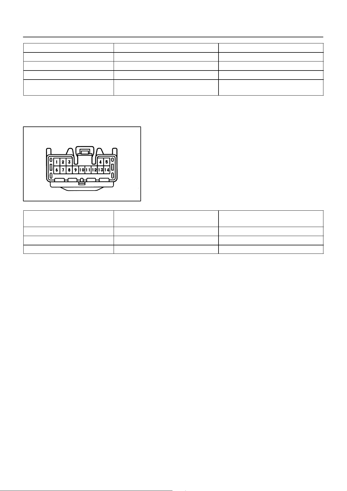
INSPECTION
1. INSPECT SEAT HEATER SWITCH CONTINUITY
Condition Te s te r c o nn e c t i on Specified condition
OFF – No continuity
ON (Left) 8 – 9 – 11 Continuity
ON (Right) 8 – 11 – 13 Continuity
Illumination 10 – 12 Continuity
If continuity is not as specified, replace the switch or bulb.
2. INSPECT SEAT HEATER SWITCH INDICATOR
(a) Connect the positive (+) lead from the battery to terminal
11 and the negative (–) lead to terminal 8.
(b) Push the switch and check that the indicator light lights
up.
If operation is not as specified, replace the switch.
Wire Harness Side
Te s te r c on n e c t i on t o
terminal number
8 – Ground Constant Continuity
9 – Ground Constant * Continuity
13 – Ground Constant * Continuity
11 – G round Ignition switch turned to ON Battery positive voltage
N13349
3. INSPECT SEAT HEATER SWITCH CIRCUIT
Disconnect the switch connector and inspect the connector on
the wire harness side, as shown.
Z14753
Condition Specified condition
*: There is resistance because this circuit is grounded through
the relay coil.
If circuit is not as specified, inspect the circuits connected to other parts.
2000 LEXUS LS400 (RM717U)
2060Author!: Date!:
Page 61

BE–198
Z08901
–BODY ELECTRICAL SEAT HEATER SYSTEM
4. INSPECT ENGINE MAIN RELAY CONTINUITY
Condition Te s te r c o nn e c t i on Specified condition
Constant
Apply B+ between
terminals 1 and 3.
1 – 3
2 – 4
4 – 5 Continuity
Continuity
If continuity is not as specified, replace the relay.
5. INSPECT ENGINE MAIN RELAY CIRCUIT
Remove the relay and inspect the connector on the junction
block side, as shown.
BE4730
Te s te r c o nn e c t i on Condition Specified condition
2 – Ground Constant Continuity
3 – Ground Constant Continuity
1 – Ground Ignition switch ON Battery positive voltage
5 – Ground Constant Battery positive voltage
If circuit is not as specified, inspect the circuits connected to other parts.
2000 LEXUS LS400 (RM717U)
2061Author!: Date!:
Page 62

–BODY ELECTRICAL SEAT HEATER SYSTEM
BE–199
Seat Cushion Side
6. Seat Cushion:
INSPECT SEAT HEATER CONTINUITY
(a) Heat the thermostat with a light.
(b) Inspect the seat heater continuity between terminals.
Connector ”A”
Connector ”B”
Te s te r c o nn e c t i on Condition Specified condition
A2 – B3 Constant Continuity
A1 – B1 Seat heater temperature bellow 25°C (77°F) Continuity
B1 – B2 Seat heater temperature bellow 25°C (77°F) Continuity
A1 – B2 Seat heater temperature bellow 25°C (77°F) Continuity
A1 – B1
B1 – B2
A1 – B2
Z14754
Seat heater temperature above
55°C (131°F)
Seat heater temperature above
45°C (113°F)
Seat heater temperature above
45°C (113°F)
No continuity
No continuity
No continuity
If continuity is not as specified, replace the seat cushion pad.
Seat Back Side
Te s te r c o nn e c t i on Condition Specified condition
1 – 3 Constant Continuity
2 – 3 Constant Continuity
2000 LEXUS LS400 (RM717U)
7. Seat Back:
INSPECT SEAT HEATER CONTINUITY
Inspect the seat heater continuity between terminals, as
shown.
Z14755
If continuity is not as specified, replace the seat back pad.
2062Author!: Date!:
Page 63

BE–196
SEAT HEATER SYSTEM
LOCATION
–
BE0CT–01
Engine Room Junction Block
! FR S/HTR Fuse
! Engine Main Relay
Seat Heater
(Seat Back)
Seat Heater
(Seat Cushion)
Seat Heater Switch
I03404
2059Author!: Date!:
Page 64

BE–194
–BODY ELECTRICAL ELECTRO CHROMIC MIRROR SYSTEM
BE0CS–01
INSPECTION
1. INSPECT ELECTRO CHROMIC INNER MIRROR OPERATION
(a) Connect the positive (+) lead from the battery to terminal
1 and the negative (–) lead to terminal 4.
(b) Connect the positive (+) leaf from the voltmeter to terminal
2 and the negative (–) lead to terminal 3.
(c) Shine an electric light on the mirror, and check that there
is battery positive voltage and mirror surface becomes
”bright” to ”dark”.
If operation is not as specified, replace the inner mirror.
Wire Harness Side
Te s te r c o nn e c t i on Condition Specified condition
4 – Ground Constant Continuity
1 – Ground Ignition switch LOCK or ACC No voltage
1 – Ground Ignition switch ON Battery positive voltage
N16074
2. INSPECT ELECTRO CHROMIC INNER MIRROR CIRCUIT
Disconnect the connector from the mirror and inspect the connector on the wire harness side, as shown.
If circuit is not as specified, inspect the circuits connected to other parts.
Z14965
2000 LEXUS LS400 (RM717U)
2057Author!: Date!:
Page 65

–BODY ELECTRICAL ELECTRO CHROMIC MIRROR SYSTEM
BE–195
”Bright”
”Dark”
”Bright”
”Dark”
w/o Memory
w/ Memory
4
3
N17035
I04603
3. INSPECT ELECTRO CHROMIC OUTER MIRROR OPERATION
w/o Driving position memory:
(a) Disconnect the outer mirror connector.
(b) Connect the positive (+) lead from the dry through battery
to terminal 2 and the negative (–) lead to terminal 1, then
check that the mirror surface become ”dark”.
(c) Reconnect to the dry through battery by the reverse order,
then check that the mirror surface become ”bright”.
If operation is not as specified, replace the mirror assembly.
4. INSPECT ELECTRO CHROMIC OUTER MIRROR OPERATION
w/ Driving position memory:
(a) Disconnect the outer mirror connector.
(b) Connect the positive (+) lead from the dry through battery
to terminal 4 and the negative (–) lead to terminal 3, then
check that the mirror surface become ”dark”.
(c) Reconnect to the dry through battery by the reverse order,
then check that the mirror surface become ”bright”.
If operation is not as specified, replace the mirror assembly.
2000 LEXUS LS400 (RM717U)
2058Author!: Date!:
Page 66

–
ELECTRO CHROMIC MIRROR SYSTEM
LOCATION
Ignition Switch
BE–193
BE0CR–01
Instrument Panel
Junction Block
! ECU–IG Fuse
Electro Chromic Inner Mirror
I03408
2056Author!: Date!:
Page 67

Slider
Upward
4
Downward
1
4
BE–187
–BODY ELECTRICAL POWER SHOULDER BELT ANCHORAGE SYSTEM
BE0CQ–01
(b)(a)
1
INSPECTION
1. INSPECT DRIVER’S HEIGHT ADJUSTABLE ANCHOR
MOTOR AND SENSOR OPERATION
(a) Connect the positive (+) lead from the battery to terminal
4 and the negative (–) lead to terminal 1, and check that
the slider moves upward.
(b) Reverse the polarity and check that the slider moves
downward.
N13338
If operation is not as specified, replace the height adjustable anchor motor.
2. Inspection using an ammeter:
4
1
INSPECT DRIVER’S HEIGHT ADJUSTABLE ANCHOR
MOTOR AND SENSOR PTC THERMISTOR OPERATION
(a) Connect the positive (+) lead from the battery to terminal
1, the positive (+) lead from the ammeter to terminal 4,
and the negative (–) lead to battery negative (–) terminal,
then move the slider to end position.
N13339
(b) Continue to apply voltage and check the current changes
to less than 0.1 A within 6 to 46 seconds.
(c) Disconnect the leads from terminals.
4
1
(d) Approximately 60 seconds later, connect the positive (+)
lead from battery to terminal 4 and the negative (–) lead
to terminal 1, and check that the slider moves to the opposite side.
If operation is not as specified, replace the height adjustable anchor motor.
N13340
2000 LEXUS LS400 (RM717U)
2050Author!: Date!:
Page 68

BE–188
–BODY ELECTRICAL POWER SHOULDER BELT ANCHORAGE SYSTEM
3. Inspection using an ammeter with a current–measur-
4
1
ing probe:
INSPECT DRIVER’S HEIGHT ADJUSTABLE ANCHOR
MOTOR AND SENSOR PTC THERMISTOR OPERATION
(a) Connect the positive (+) lead from the battery to terminal
1 and the negative (–) lead to terminal 4.
(b) Attach a current–measuring probe to the negative (–)
N13380
lead, and move the slider to the end position.
(c) Check the current changes to less than 0.1 A with 6 to 46
seconds.
Slider
Upward
2
4
Downward
2
1
1
1
N13340
N13341
(d) Disconnect the leads from terminals.
(e) Approximately 60 seconds later, reverse the polarity, and
check that the slider moves to the opposite side.
If operation is not as specified, replace the height adjustable anchor motor.
4. INSPECT PASSENGER’S HEIGHT ADJUSTABLE ANCHOR MOTOR AND SENSOR OPERATION
(a) Connect the positive (+) lead from the battery to terminal
2 and the negative (–) lead to terminal 1, and check that
the slider moves upward.
(b) Reverse the polarity and check that the slider moves
downward.
If operation is not as specified, replace the height adjustable anchor motor.
2000 LEXUS LS400 (RM717U)
2051Author!: Date!:
Page 69

BE–189
–BODY ELECTRICAL POWER SHOULDER BELT ANCHORAGE SYSTEM
5. Inspection using an ammeter:
2
1
INSPECT PASSENGER’S HEIGHT ADJUSTABLE ANCHOR MOTOR AND SENSOR PTC THERMISTOR OPERATION
(a) Connect the positive (+) lead from the battery to terminal
1, the positive (+) lead from the ammeter to terminal 2,
and the negative (–) lead to battery negative (–) terminal,
then move the slider to end position.
N13342
(b) Continue to apply voltage and check the current changes
to less than 0.1 A within 6 to 46 seconds.
(c) Disconnect the leads from terminals.
(d) Approximately 60 seconds later, connect the positive (+)
2
1
lead from battery to terminal 2 and the negative (–) lead
to terminal 1, and check that the slider moves to the opposite side.
If operation is not as specified, replace the height adjustable anchor motor.
N13343
6. Inspection using an ammeter with a current–measur-
2
1
ing probe:
INSPECT PASSENGER’S HEIGHT ADJUSTABLE ANCHOR MOTOR AND SENSOR PTC THERMISTOR OPERATION
(a) Connect the positive (+) lead from the battery to terminal
1 and the negative (–) lead to terminal 2.
(b) Attach a current–measuring probe to the negative (–)
N13344
lead, and move the slider to the end position.
(c) Check the current changes to less than 0.1 A within 6 to
46 seconds.
2000 LEXUS LS400 (RM717U)
2052Author!: Date!:
Page 70

BE–190
Up
Down
–BODY ELECTRICAL POWER SHOULDER BELT ANCHORAGE SYSTEM
(d) Disconnect the leads from terminals.
2
1
(e) Approximately 60 seconds later, reverse the polarity and
check that the slider moves to the opposite side.
If operation is not as specified, replace the height adjustable anchor motor.
N13343
7. INSPECT DRIVER’S SHOULDER BE LT ADJUST
SWITCH CIRCUIT (See page DI–755)
8. INSPECT DRIVER’S SHOULDER BE LT ADJUST
SWITCH CONTINUITY
Switch position Te s te r c o nn e c t i on Specified condition
UP 2 – 3 Continuity
OFF – No continuity
Z08899
9. INSPECT PASSENGER’S SHOULDER BELT ADJUST
DOWN 1 – 3 Continuity
SWITCH CONTINUITY
Wire Harness Side
h–7–1
Te s te r c o nn e c t i on Condition Specified condition
6 – Ground Constant Continuity
7 – Ground Constant Continuity
Switch position Te s te r c o nn e c t i on Specified condition
UP 1 – 7 Continuity
OFF – No continuity
DOWN 2 – 6 Continuity
If continuity is not as specified, replace the switch.
10. INSPECT PASSENGER’S SHOULDER BELT ADJUST
SWITCH CIRCUIT
Disconnect the connector from the switch and inspect the connector on the wire harness side, as shown.
Z08795
If circuit is not as specified, inspect wire harness.
2000 LEXUS LS400 (RM717U)
2053Author!: Date!:
Page 71

BE–191
–BODY ELECTRICAL POWER SHOULDER BELT ANCHORAGE SYSTEM
11. Upward:
1
4
INSPECT SHOULDER BELT ANCHOR RELAY OPERATION
(a) Connect the positive (+) lead from the battery to terminal
7
5
4 and the negative (–) lead to terminal 5 and 7.
(b) Connect the positive (+) lead from the voltmeter to termi-
nal 1 and negative (–) lead to battery negative (–) terminal, and check that there is battery positive voltage.
N13346
8
Wire Harness Side
S–8–1
3
12. Downward:
INSPECT SHOULDER BELT ANCHOR RELAY OPERA-
4
TION
(a) Connect the positive (+) lead from the battery to terminal
7
4 and the negative (–) lead to terminal 7 and 8.
(b) Connect the positive (+) lead from the voltmeter to termi-
nal 3 and negative (–) lead to battery negative (–) terminal, and check that there is battery positive voltage.
N13347
If operation is not as specified, replace rheostat light control.
13. INSPECT SHOULDER BELT ANCHOR RELAY CIRCUIT
Disconnect the connector from the rheostat light control and inspect the connector on the wire harness side, as shown.
Z14752
Te s te r c o nn e c t i on Condition Specified condition
5 – Ground Seat belt adjust switch position UP Continuity
7 – Ground Constant Continuity
8 – Ground Seat belt adjust switch position DOWN Continuity
4 – Ground Constant Battery positive voltage
2000 LEXUS LS400 (RM717U)
If circuit is not as specified, inspect the circuits connected to other parts.
2054Author!: Date!:
Page 72

BE–192
–BODY ELECTRICAL POWER SHOULDER BELT ANCHORAGE SYSTEM
Wire Harness Side
Connector ”A”
Connector ”B”
e–12–1
h–22–1
Te s te r c o nn e c t i on Condition Specified condition
A7 – Ground
B9 – Ground
A4 – Ground
B22 – Ground
B15 – Ground Ignition switch turned to ON Battery positive voltage
A6 – B8
B8 – B17 Constant Approx. 4 – 6 kΩ
14. INSPECT TILT AND TELESCOPIC ECU CIRCUIT
Disconnect the ECU connector, and inspect the connector on
wire harness side, as shown.
Z14981
Constant Continuity
Constant Battery positive voltage
Move the driver’s height adjustable
anchor sensor
Resistance changes from Approx. 0 to 5 kΩ
If circuit is not as specified, inspect the circuit connected to other parts.
2000 LEXUS LS400 (RM717U)
2055Author!: Date!:
Page 73

BE–186
–
POWER SHOULDER BELT ANCHORAGE SYSTEM
LOCATION
Tilt and Telescopic ECU
BE0CP–01
Driver Door ECU
Drive Position Memory
and Return Switch
! Shoulder Belt Adjust Switch
Ignition Switch
Power Shoulder
Belt Anchor Relay
Shoulder Belt Adjust Switch
Height Adjustable Anchor Motor
I03235
2049Author!: Date!:
Page 74

BE–182
Left/Right Adjustment Switch
9
8
7
6
5
Mirror Switch
I04167
–BODY ELECTRICAL POWER MIRROR CONTROL SYSTEM
BE11W–01
INSPECTION
1. INSPECT MIRROR SWITCH CONTINUITY
Switch position Te s te r c o nn e c t i on Resistance (Ω)
LEFT 8 – 9 100
RIGHT 8 – 9 0
Illumination 5 – 6 Continuity
If continuity is not as specified, replace the switch.
2. INSPECT MIRROR SWITCH RESISTANCE
Measure resistance between terminals 7 and 9 at each switch
position, as shown in the chart.
Switch position Resistance (Ω)
UP Approx. 100
RIGHT 250
DOWN 470
LEFT 800
If resistance is not as specified, replace the switch.
3. INSPECT MIRROR SWITCH CIRCUIT
(See page DI–452)
6
5
RETURN RETRACT
3
N13659
2
1
I09236
4
4. INSPECT MIRROR SWITCH INDICATOR LIGHT OPERATION
Connect the positive (+) lead from the battery to terminal 5 and
the negative (–) lead to terminal 6, and check that the indicator
light does not light up, replace the switch.
5. CANADA and TAIWAN models only:
INSPECT RETRACT SWITCH CONTINUITY
Switch position Te s te r c o nn e c t i on Specified condition
RETURN – No continuity
RETRACT 1 – 2 Continuity
6. CANADA and TAIWAN models only:
INSPECT RETRACT SWITCH INDICATOR OPERATION
Connect the positive (+) lead from the battery to terminal 4 and
negative (–) lead to terminal3 and check that the indicator does
no light up, replace the switch.
2000 LEXUS LS400 (RM717U)
I09237
2045Author!: Date!:
Page 75

N13476
BE–183
–BODY ELECTRICAL POWER MIRROR CONTROL SYSTEM
7. INSPECT MIRROR MOTOR OPERATION
w/o Driving position memory:
(a) Connect the positive (+) lead from the battery to terminal
6 and negative (–) lead to terminal 5, then check that the
mirror turns to left side.
(b) Reverse the polarity and check that the mirror turns to
right side.
(c) Connect the positive (+) lead from the battery to terminal
4 and negative (–) lead to terminal 5, then check that the
mirror turns upward.
(d) Reverse the polarity and check that the mirror turns down-
ward.
12 11
11 10
12 11
11 10
N13477
8. INSPECT MIRROR MOTOR OPERATION
w/ Driving position memory:
(a) Connect the positive (+) lead from the battery to terminal
11 and negative (–) lead to terminal 12, then check that
the mirror turns to left side.
(b) Reverse the polarity and check that the mirror turns to
right side.
I04601
(c) Connect the positive (+) lead from the battery to terminal
11 and negative (–) lead to terminal 10, then check that
the mirror turns upward.
(d) Reverse the polarity and check that the mirror turns down-
ward.
I04602
7
13
11
10
2000 LEXUS LS400 (RM717U)
9. INSPECT MIRROR POSITION SENSORS
HINT:
Strip off the vinyl tape of the connector and remove terminals
6, 7, 10, 11, 12, 13 and 14 from the connector housing.
6
(a) Connect a series of three 1.5 V dry cell batteries.
(b) Connect the positive (+) lead from the dry cell batteries to
terminal 7 and the negative (–) lead to terminal 6.
(c) Connect the positive (+) lead from the voltmeter to termi-
I04605
nal 13 and the negative (–) lead to terminal 6.
2046Author!: Date!:
Page 76

BE–184
14
12
14
12
13
11
–BODY ELECTRICAL POWER MIRROR CONTROL SYSTEM
(d) Apply battery positive voltage to terminals 10 and 11, then
check that the voltage gradually changes according to the
7
table below while the mirror moves between the uppermost position and lowermost position.
10
6
I04606
Mirror
position
Voltage 2.8 – 5.0
Lowermost
If voltage value is not as specified, replace the motor assembly.
Mirror
position
Changes
gradually
Uppermost
0 – 0.9
(e) Disconnect the 4 leads of the battery and voltmeter.
(f) Connect the positive (+) lead from the voltmeter to termi-
7
nal 14 and negative (–) lead to terminal 6.
(g) Apply battery positive voltage to terminals 11 and 12, then
6
inspect that the voltage gradually changes according to
the table below while the mirror moves between the left–
11
I04607
7
most position and right–most position.
Mirror
position
Voltage
LEFT
Voltage
RIGHT
Left–most
2.8 – 5.0
0 – 0.9
Mirror
position
Changes
gradually
Changes
gradually
Right–most
0 – 0.9
2.8 –5.0
If voltage value is not as specified, replace the motor assembly.
6
11
SW1
SW2
SET Switch
I04608
N13484
10. INSPECT DRIVING POSITION MEMORY AND RETURN SWITCH CONTINUITY
Switch position Te s te r c o nn e c t i on Specified condition
SET switch ON 3 – 4 Continuity
Return SW1 ON 3 – 7 Continuity
Return SW2 ON 3 – 6 Continuity
If continuity is not as specified, replace the switch.
If continuity is as specified, inspect the switch circuit.
11. INSPECT DRIVING POSITION MEMORY AND RETURN SWITCH CIRCUIT (See page DI–755)
2000 LEXUS LS400 (RM717U)
2047Author!: Date!:
Page 77

BE–185
–BODY ELECTRICAL POWER MIRROR CONTROL SYSTEM
12. INSPECT ELECTRICAL RETRACT MOTOR CONTINU-
2
1
ITY
(a) Connect the positive (+) lead from the battery to terminal
2 and negative (–) lead to terminal 1, check that the no
continuity exists in folding position.
(b) Reverse the polarity, check that no continuity exists in
driving position.
If operation is not as specified, replace the mirror assembly.
I09238
13. INSPECT ELECTRICAL RETRACT MOTOR CONTINU-
2
1
ITY
At drive position:
(a) Connect the positive (+) lead from the battery to terminal
2 and negative (–) lead to terminal 1, check that continuity
exists in folding position.
(b) Reverse the polarity, check that no continuity exists in
driving position.
I09239
If operation is not as specified, replace the mirror assembly.
14. INSPECT ELECTRICAL RETRACT MOTOR CONTINU-
2
1
ITY
Between drive position and retract position:
(a) Connect the positive (+) lead from the battery to terminal
2 and negative (–) lead to terminal 1, check that continuity
exists in folding position.
(b) Reverse the polarity, check that no continuity exists in
driving position.
I09240
If operation is not as specified, replace the mirror assembly.
15. INSPECT MIRROR MOTOR OPERATION
1
2
(a) Connect the positive (+) lead from the battery to terminal
2 and negative (–) lead to terminal 1.
(b) Check that the motor turns (moves to folding position).
NOTICE:
These tests must be performed quickly (within 5 – 10 seconds) to prevent the coil from burning out.
I09241
(c) Connect the positive (+) lead from the battery to terminal
2
1
1 and negative (–) lead to terminal 2.
(d) Check that the motor turns (moves to driving position).
NOTICE:
These tests must be performed quickly (within 5 – 10 seconds) to prevent the coil from burning out.
If operation is not as specified, replace the mirror assembly.
2000 LEXUS LS400 (RM717U)
I09242
2048Author!: Date!:
Page 78

–
POWER MIRROR CONTROL SYSTEM
LOCATION
BE–181
BE0CN–01
Engine Room Junction Block
! HORN Fuse
Ignition Switch
Tilt & Telescopic ECU
Body ECU
Driver Door ECU
Instrument Panel Junction Block
! RADIO No.2 Fuse
Front Passenger Door ECU
Driving Position Memory
& Return Switches
I03406
2044Author!: Date!:
Page 79

Front vertical Rear vertical
UP
DOWN
Slide
UP
DOWN
BACKFRONT
Z16936
–BODY ELECTRICAL POWER SEAT CONTROL SYSTEM (w/o Driving
Position Memory)
BE–171
BE121–01
INSPECTION
1. INSPECT FRONT POWER SEAT SWITCH CONTINUITY
Slide switch
Switch position Te s te r c o nn e c t i on Specified condition
FRONT
OFF
BACK
Front vertical switch
Switch position Te s te r c o nn e c t i on Specified condition
UP
OFF
DOWN
Rear vertical switch
11 – 14
12 – 13
11 – 13
12 – 13
11 – 13
12 – 14
9 – 14
10 – 13
9 – 13
10 – 13
9 – 13
10 – 14
Continuity
Continuity
Continuity
Continuity
Continuity
Continuity
Reclining
FORWARD
DOWN
UP
REAR
Head Rest
Switch position Te s te r c o nn e c t i on Specified condition
UP
OFF
DOWN
5 – 14
6 – 13
5 – 13
6 – 13
5 – 13
6 – 14
Continuity
Continuity
Continuity
Reclining switch
Switch position Te s te r c o nn e c t i on Specified condition
FORWARD
OFF
REAR
4 – 14
3 – 13
4 – 13
3 – 13
4 – 13
3 – 14
Continuity
Continuity
Continuity
Headrest switch
Switch position Te s te r c o nn e c t i on Specified condition
UP
OFF
DOWN
14 – 15
13 – 16
13 – 15
13 – 16
13 – 15
14 – 16
Continuity
Continuity
Continuity
If continuity is not as specified, replace the switch.
2000 LEXUS LS400 (RM717U)
Z16937
2034Author!: Date!:
Page 80

BE–172
–BODY ELECTRICAL POWER SEAT CONTROL SYSTEM (w/o Driving
Position Memory)
Wire Harness Side
1
2
7
5
6
13
11
12
Te s te r c o nn e c t i on Condition Specified condition
13 – Ground Constant Continuity
14 – Ground Constant Battery positive voltage
14
2. INSPECT POWER SEAT SWITCH CIRCUIT
(a) Disconnect the switch connector and connect the seat
wire harness to the floor wire harness.
(b) Inspect the connector on the wire harness side, as
4
3
8
10
9
16
15
Z09315
shown.
If circuit is not as specified, inspect the circuits connected to other parts.
3. INSPECT LUMBAR SUPPORT SWITCH CONTINUITY
( ): Passenger’s Seat
FORWARD RELEASE
Z07464
Switch position Te s te r c o nn e c t i on Specified condition
FORWARD
OFF
RELEASE
1(1) – 4(4)
2(2) – 3(3)
1(2) – 3(3)
2(2) – 3(4)
1(1) – 3(3)
2(2) – 4(4)
Continuity
Continuity
Continuity
If continuity is not as specified, replace the switch.
2000 LEXUS LS400 (RM717U)
2035Author!: Date!:
Page 81

–BODY ELECTRICAL POWER SEAT CONTROL SYSTEM (w/o Driving
Position Memory)
BE–173
Wire Harness Side
4. INSPECT LUMBAR SUPPORT SWITCH CIRCUIT
(a) Disconnect the switch connector and connect the seat
wire harness to the floor wire harness.
(b) Inspect the connector on the wire harness side, as
shown.
Z06678
( ): Passenger’s Seat
Te s te r c o nn e c t i on Condition Specified condition
3 – Ground (2 – Ground) Constant Continuity
4 – Ground (1 – Ground) Constant Battery positive voltage
If circuit is not as specified, inspect the circuits connected to other parts.
5. INSPECT SLIDE MOTOR OPERATION
(a) Connect the positive (+) lead from the battery to terminal
2 and the negative (–) lead to terminal 1 and check that
the motor turns counterclockwise.
(b) Reverse the polarity and check that the motor turns clock-
wise.
21
–+
N07798
If operation is not as specified, replace the motor.
2000 LEXUS LS400 (RM717U)
2
–
+
2
–+
1
–+
1
Z14972
Z07885
6. Driver’s seat:
INSPECT SLIDE MOTOR PTC THERMISTOR OPERATION
(a) Connect the positive (+) lead from the battery to terminal
2, the positive (+) lead from the ammeter to terminal 1,
and the negative (–) lead to battery negative (–) terminal,
then move the seat to front position.
(b) Continue to apply voltage and check that the current
changes to less than 1 ampere with 4 to 90 seconds.
(c) Disconnect the lead from terminals.
(d) Approximately 60 seconds later , connect the positive (+)
lead from battery to terminal 1 and the negative (–) lead
to terminal 2 and check that the seat begins to move backwards.
If operation is not as specified, replace the motor.
2036Author!: Date!:
Page 82

BE–174
(a) (b)
–BODY ELECTRICAL POWER SEAT CONTROL SYSTEM (w/o Driving
Position Memory)
7. INSPECT FRONT VERTICAL MOTOR OPERATION
(a) Connect the positive (+) lead from the battery to terminal
2 and the negative (–) lead to terminal 1 and check that
the motor turns clockwise.
(b) Reverse the polarity and check that the motor turns coun-
terclockwise.
If operation is not as specified, replace the motor.
21
–+
21
2
–+
Z14969
1
Z14970
8. Driver’s Seat:
INSPECT FRONT VERTICAL MOTOR PTC THERMISTOR OPERATION
(a) Connect the positive (+) lead from the battery to terminal
1, the positive (+) lead from the ammeter to terminal 2 and
the negative (–) lead to battery negative (–) terminal, then
move the front edge of seat cushion to the highest position.
(b) Continue to apply voltage, and check the current changes
to less than 1 ampere with 4 to 90 seconds.
(c) Disconnect the leads from terminals.
(d) Approximately 60 seconds later, connect the positive (+)
lead from battery to terminal 2 and the negative (–) lead
to terminal 1, and check that the seat cushion begins to
descend.
If operation is not as specified, replace the motor.
21
2000 LEXUS LS400 (RM717U)
Z07887
9. INSPECT REAR VERTICAL MOTOR OPERATION
(a) Connect the positive (+) lead from the battery to terminal
2 and the negative (–) lead to terminal 1, and check that
the motor turns clockwise.
(b) Reverse the polarity, and check that the motor turns coun-
terclockwise.
If operation is not as specified, replace the motor.
–+
N07798
2037Author!: Date!:
Page 83

2
2
–+
1
–+
1
Z14971
–BODY ELECTRICAL POWER SEAT CONTROL SYSTEM (w/o Driving
Position Memory)
BE–175
10. Driver’s seat:
INSPECT REAR VERTICAL MOTOR PTC THERMISTOR OPERATION
(a) Connect the positive (+) lead from the battery to terminal
2, the positive (+) lead from the ammeter to terminal 1 and
the negative (–) lead to battery negative (–) terminal, then
move the rear edge of seat cushion to the highest position.
(b) Continue to apply voltage, and check that the current
changes to less than 1 ampere with 4 to 90 seconds.
(c) Disconnect the leads from terminals.
(d) Approximately 60 seconds later, connect the positive (+)
lead from battery to terminal 1 and the negative (–) lead
to terminal 2, and check that the seat cushion begins to
descend.
If operation is not as specified, replace the motor.
(a) (b)
21
–+
21
Z07469
11. Driver’s Seat:
INSPECT RECLINING MOTOR OPERATION
(a) Connect the positive (+) lead from the battery to terminal
2 and the negative (–) lead to terminal 1, and check that
the motor turns counterclockwise.
(b) Reverse the polarity, and check that the motor turns
clockwise.
If operation is not as specified, replace the motor.
–+
Z14969
2000 LEXUS LS400 (RM717U)
12. Driver’s Seat:
2
1
INSPECT RECLINING MOTOR PTC THERMISTOR OPERATION
(a) Connect the positive (+) lead from the battery to terminal
1, the positive (+) lead from the ammeter to terminal 2 and
the negative (–) lead to battery negative (–) terminal, then
–
+
–+
Z14973
recline the seat back to the most forward position.
(b) Continue to apply voltage, and check that the current
change to less than 1 ampere with 4 to 90 seconds.
2038Author!: Date!:
Page 84

BE–176
(c) Disconnect the lead from terminals.
21
(d) Approximately 60 seconds later, connect the positive (+)
If operation is not as specified, replace the motor.
–+
Z07474
13. INSPECT LUMBAR SUPPORT MOTOR OPERATION
21
(a) Connect the positive (+) lead from the battery to terminal
–BODY ELECTRICAL POWER SEAT CONTROL SYSTEM (w/o Driving
Position Memory)
lead from battery to terminal 2 and the negative (–) lead
to terminal 1, check that the seat back starts to fall backwards.
1 and the negative (–) lead to terminal 2, and check that
the lumbar support moves release side.
N21675
(b) Reverse the polarity, and check that the lumbar support
21
If operation is not as specified, replace the motor.
N21676
14. Driver’s Seat:
21
(a) Connect the positive (+) lead from the battery to terminal
N13487
2
1
(b) Continue to apply voltage, and check that the current
(c) Disconnect the leads from terminals.
(d) Approximately 60 seconds later, connect the positive (+)
If operation is not as specified, replace the motor.
moves forward.
INSPECT LUMBAR SUPPORT MOTOR PTC THERMISTOR OPERATION
1, the positive (+) lead from the ammeter to terminal 2 and
the negative (–) lead to battery negative (–) terminal, then
move the front edge of seat cushion to the highest position.
changes to less than 1 ampere with 4 to 90 seconds.
lead from battery to terminal 2 and the negative (–) lead
to terminal 1, and check that the seat cushion begins to
descend.
2000 LEXUS LS400 (RM717U)
N13488
2039Author!: Date!:
Page 85

FRONT
UP
DOWN
REAR
Connector ”A”
FRONT
REAR
Connector ”B”
I09308
–BODY ELECTRICAL POWER SEAT CONTROL SYSTEM (w/o Driving
Position Memory)
15. Taiwan Models Only:
INSPECT REAR POWER SEAT SWITCH CONTINUITY
Slide switch LH:
Switch position Te s te r c o nn e c t i on Specified condition
FRONT
OFF
REAR
B1 – B5
B5 – B7
B1 – B7
B5 – B7
B1 – B7
B5 – B6
Continuity
Continuity
Continuity
Slide switch RH:
Switch position Te s te r c o nn e c t i on Specified condition
FRONT
OFF
REAR
B4 – B6
B9 – B7
B4 – B7
B7 – B10
B4 – B7
B7 – B10
Continuity
Continuity
Continuity
Headrest switch LH (for vertical):
BE–177
Switch position Te s te r c o nn e c t i on Specified condition
UP
OFF
DOWN
B2 – B6
B7 – B8
B2 – B7
B7 – B8
B2 – B7
B6 – B8
Continuity
Continuity
Continuity
Headrest switch RH (for vertical):
Switch position Te s te r c o nn e c t i on Specified condition
UP
OFF
DOWN
B3 – B6
B7 – B9
B3 – B7
B7 – B9
B3 – B7
B6 – B9
Continuity
Continuity
Continuity
Headrest switch LH (for turning)
Switch position Te s te r c o nn e c t i on Specified condition
FRONT A4 –B7 Continuity
OFF – No continuity
REAR A5 –B7 Continuity
Headrest switch RH (for turning)
2000 LEXUS LS400 (RM717U)
Switch position Te s te r c o nn e c t i on Specified condition
FRONT A4 –B7 Continuity
OFF – No continuity
REAR A5 –B7 Continuity
If continuity is not as specified, replace the switch.
2040Author!: Date!:
Page 86

BE–178
–BODY ELECTRICAL POWER SEAT CONTROL SYSTEM (w/o Driving
Position Memory)
Wire Harness Side
Connector ”A”
Te s te r c o nn e c t i on Condition Specified condition
B7 – Ground Constant Continuity
B8 – Ground Constant Battery positive voltage
21
Connector ”B”
–+
16. INSPECT REAR POWER SEAT SWITCH CIRCUIT
(a) Disconnect the switch connector and connect the seat
wire harness to the floor wire harness.
(b) Inspect the connector on the wire harness side, as
shown.
I10509
If circuit is not as specified, inspect the circuits connected to other parts.
17. INSPECT SLIDE MOTOR OPERATION
(a) Connect the positive (+) lead from the battery to terminal
2 and the negative (–) lead to terminal 1 and check that
the motor turns counterclockwise.
(b) Reverse the polarity and check that the motor turns clock-
wise.
If operation is not as specified, replace the motor.
N07798
2000 LEXUS LS400 (RM717U)
18. INSPECT SLIDE MOTOR PTC THERMISTOR OPERA-
2
1
TION
(a) Connect the positive (+) lead from the battery to terminal
2, the positive (+) lead from the ammeter to terminal 1,
and the negative (–) lead to battery negative (–) terminal,
then move the seat to front position.
(b) Continue to apply voltage and check that the current
changes to less than 1 ampere with 4 to 90 seconds.
I09301
(c) Disconnect the lead from terminals.
2
1
(d) Approximately 60 seconds later , connect the positive (+)
lead from battery to terminal 1 and the negative (–) lead
to terminal 2 and check that the seat begins to move backwards.
If operation is not as specified, replace the motor.
I09300
2041Author!: Date!:
Page 87

(a) (b)
21
21
–BODY ELECTRICAL POWER SEAT CONTROL SYSTEM (w/o Driving
Position Memory)
BE–179
19. INSPECT HEADREST MOTOR OPERATION
(For vertical)
(a) Connect the positive (+) lead from the battery to terminal
2 and the negative (–) lead to terminal 1, and check that
the motor turns counterclockwise.
(b) Reverse the polarity, and check that the motor turns
clockwise.
If operation is not as specified, replace the motor.
To ”DOWN”
I09261
20. INSPECT HEADREST MOTOR CIRCUIT BREAKER
1
OPERATION (For vertical)
(a) Connect the positive (+) lead from the battery to terminal
1 and negative (–) lead to terminal 2 on the motor connec-
2
I09282
tor and move the headrest to DOWN position.
(b) Continue to apply voltage, check that there is a circuit
1
breaker operation noise within 4 to 60 seconds.
(c) Reverse the polarity check that the headrest begins to
move UP side within approx. 60 seconds.
2
I09281
If operation is not as specified, replace the headrest.
2000 LEXUS LS400 (RM717U)
2042Author!: Date!:
Page 88

BE–180
–BODY ELECTRICAL POWER SEAT CONTROL SYSTEM (w/o Driving
Position Memory)
FRONT
REAR
2
1
21. INSPECT HEADREST MOTOR OPERATION
(For turning)
(a) Connect the positive (+) lead from the battery to terminal
2 and negative (–) lead to terminal 4.
4
3
(b) Connect the negative (–) lead to each terminal and check
that the headrest turns at each position, as shown in the
chart.
Te s te r c o nn e c t i on Position
I09283
1 FRONT
3 REAR
If operation is not as specified, replace the headrest.
2000 LEXUS LS400 (RM717U)
2043Author!: Date!:
Page 89

–BODY ELECTRICAL POWER SEAT CONTROL SYSTEM (w/o Driving
Position Memory)
POWER SEAT CONTROL SYSTEM (w/o Driving Position
Memory)
LOCATION
Engine Room
Junction Block
! FR S/HTR Fuse
BE–169
BE120–01
Lumbar Support Motor
Lumbar Support Switch
Poser Seat Switch
Front Vertical Motor
Slide Motor
Reclining Motor
Lumbar Support
Motor
Lumbar Support Motor
Lumbar Support Switch
Rear Vertical Motor
Poser Seat Switch
Slide Motor
Front Vertical Motor
I03262
2000 LEXUS LS400 (RM717U)
2032Author!: Date!:
Page 90

BE–170
TAIWAN models:
–BODY ELECTRICAL POWER SEAT CONTROL SYSTEM (w/o Driving
Position Memory)
Headrest Motor RH
(for turning)
Headrest Motor RH
(for vertical)
Rear Power Seat Switch
Headrest Motor LH
(for turning)
Headrest Motor LH
(for vertical)
Slide Motor RH
Slide Motor LH
I09274
2000 LEXUS LS400 (RM717U)
2033Author!: Date!:
Page 91

BE–164
I04154
–BODY ELECTRICAL WIRELESS DOOR LOCK CONTROL SYSTEM
BE0CK–01
REPLACEMENT
1. REPLACE TRANSMITTER (LITHIUM) BATTERY
NOTICE:
Special caution should be taken for handling each component as they are precision electronic components.
(a) Using a screwdriver, remove the screw and cover.
NOTICE:
Do not pry out the cover forcibly.
HINT:
Push the cover with a finger as shown in the illustration, so that
there becomes clearance, then pry out the cover from that
clearance.
(b) Remove the transmitter.
O–Ring
Terminal
I04155
I04156
(c) Using a screwdriver, remove the 2 screws and cover.
(d) Remove the battery (lithium battery).
NOTICE:
! Do not push the terminals with a finger.
! If prying up the battery (lithium battery) forcibly to re-
move, the terminals are deformed.
(e) Install a battery (lithium battery) as shown in the illustra-
tion.
NOTICE:
Face the battery upward. Take care not to deform the terminals.
(f) Check that O–ring is not distorted or slipped off, and
install the cover.
(g) Using a screwdriver, tighten the 2 screws.
NOTICE:
When the shrews are tightened loosely, it might cause
faulty contact of battery (lithium battery) and terminals.
(h) Assemble the transmitter to the key plate and the cover.
(i) Using a screwdriver, tighten the screw.
2000 LEXUS LS400 (RM717U)
2027Author!: Date!:
Page 92

BE–165
–BODY ELECTRICAL WIRELESS DOOR LOCK CONTROL SYSTEM
2. REPLACE DOOR CONTROL RECEIVER AND TRANSMITTER
NOTICE:
When replacing the door control receiver and transmitter,
registration of recognition code is necessary because they
are provided as a single components.
(a) Select the operation mode to perform from the following
operation modes.
! Add mode
! Rewrite mode
! Prohibition mode
! Confirmation mode
HINT:
! The add mode is used to retain codes already registered
while you register new recognition codes. This mode is
used when adding a transmitter. However, if the number
of registered codes exceeds 4 codes, previously registered codes are correspondingly erased in order, starting
from the first registered code.
! The rewrite mode is used to erase all previously regis-
tered codes and register only new recognition codes.
! The prohibition mode is used to erase all registered codes
and cancels the wireless door lock function. Use this
mode when the transmitter is lost.
! The confirmation mode is for confirming few many recog-
nition codes ar already registered before you register
additional recognition codes.
(b) Follow the chart on the following page to register the
transmitter recognition code at the wireless door lock control receiver.
HINT:
! When procedure is out of the specified, the operation re-
turns to normal operation.
! Maximum 4 recognition codes can be registered.
2000 LEXUS LS400 (RM717U)
2028Author!: Date!:
Page 93

BE–166
–BODY ELECTRICAL WIRELESS DOOR LOCK CONTROL SYSTEM
Start registration of recognition code
The vehicle should be in the following conditions.
" The key is not inserted in the ignition key cylinder.
" Driver’s door is OPEN. (Other doors are CLOSED)
" Driver’s door is UNLOCKED. (Other doors are CLOSED)
Insert the key into the ignition key cylinder, then pull it out.
Press the door lock control switch (for manual operation) 5 times to
LOCK/UNLOCK at approx. 1 sec. interval.
1st time 2nd time 3rd time 4th time 5th time
Within
40 secs.
Within
40 secs.
LOCK
OFF
UNLOCK
LOCK
OFF
UNLOCK
Approx.
1 sec.
Approx.
1 sec.
Close the driver’s door, then open it.
Again press the door lock control switch (for manual operation) 5 times to
LOCK/UNLOCK at approx. 1 sec. interval.
1st time 2nd time 3rd time 4th time 5th time
Approx.
1 sec.
Approx.
1 sec.
2000 LEXUS LS400 (RM717U)
Insert the key into the ignition key cylinder.
2029Author!: Date!:
Page 94

BE–167
–BODY ELECTRICAL WIRELESS DOOR LOCK CONTROL SYSTEM
Turn the ignition switch from ON to LOCK at approx. 1 sec. interval 1 to 5 times to select the mode.
Add mode
ON – LOCK change occurs 1 time
Approx. 1 sec.
ON
LOCK
Rewrite mode
ON – LOCK change occurs 2 times
Approx.
1 sec.
Approx.
1 sec.
ON
LOCK
Pull out the key plate from the ignition key cylinder.
When add mode or rewrite mode
is selected.
ON
LOCK
ON
LOCK
Confirmation mode
ON – LOCK change occurs 3 times
Approx.
1 sec.
Approx.
1 sec.
Prohibition mode
ON – LOCK change occurs 5 times
Approx.
1 sec.
Approx.
1 sec.
When prohibition
mode is selected.
When confirmation
mode is selected.
Within
3 secs.
MPX body ECU automatically performs
the LOCK–UNLOCK operation once
or twice at 1 sec, interval to inform the
operator that either the add mode or
rewrite mode has been selected.
LOCK–UNLOCK occurs once
Indicates that add mode has been selected.
1 sec.
LOCK
UNLOCK
LOCK–UNLOCK occurs twice
Indicates that rewrite mode has been
selected.
1 sec.
1 sec.
LOCK
UNLOCK
MPX body ECU automatically performs the
LOCK–UNLOCK operation 1 to 4 times at
2 sec. interval to inform the operator of
the number of the registered codes.
HINT:
When the number of the registered code
is 0, the operation is automatically
performed 5 times.
Example:
When the operation is performed twice, it
directs that 2 type of recognition code
have been registered.
1st time 2nd time
2 secs. 2 secs.
LOCK
UNLOCK
Registration of recognition code (Confirmation
mode and probation mode) is completed.
2000 LEXUS LS400 (RM717U)
2030Author!: Date!:
Page 95

BE–168
–BODY ELECTRICAL WIRELESS DOOR LOCK CONTROL SYSTEM
When prohibition
mode is selected.
Within
40 secs.
Within 3 secs.
Within
3 secs.
MPX body performs operates LOCK–UNLOCK operation 5 times at a 1 sec.
interval to inform the operator that prohibition mode has been selected.
Approx.
Approx.
1 sec.
1 sec.
ON
LOCK
Press the lock and unlock switches on the transmitter simultaneously within 1.5 sec.
Press again either of switches on the transmitter for more than 1 sec.
MPX body ECU automatically performs LOCK–UNLOCK operation once or
twice at a 1 sec. interval to inform the operator that it has received the signal
from the transmitter.
LOCK–UNLOCK occurs once
Registration of recognition code is completed
LOCK–UNLOCK occurs twice
Registration of recognition code has not been completed.
" Recognition code received first time and second time did not match.
If they are not performed, the mode returns to the normal mode, then start with
”Start registration of recognition code”.
Proceed to finish registration
Proceed to continue registration
Within 40 secs.
If even one of the following conditions is satisfied, registration of recognition
codes in completed.
" 40 secs. elapses since the MPX body ECU response.
" The driver’s door is closed.
" The key plate is inserted in the ignition key cylinder.
" 4 types recognition codes are registration at one time.
Registration of recognition codes (add mode or rewrite mode) is completed.
2000 LEXUS LS400 (RM717U)
2031Author!: Date!:
Page 96

BE–160
I04149
–BODY ELECTRICAL WIRELESS DOOR LOCK CONTROL SYSTEM
BE0CJ–01
INSPECTION
1. INSPECT WIRELESS DOOR LOCK TRANSMITTER
OPERATION
HINT:
Refer to ”Wireless door lock control receiver and transmitter replacement”.
(a) Using a screwdriver, remove the screw and cover.
(b) Remove the battery (lithium battery).
(c) Install a new or normal battery (lithium battery).
HINT:
When a new or normal battery can not be obtained, connect 2
new 1.5 V batteries in series, connect the battery (+) to the battery receptacle side terminal and battery (–) to the bottom terminal, then apply 3 V voltage to the transmitter.
(d) In the location where is approx. 1 M away from driver’s
outside handle in the right direction, face the key plate of
the transmitter to the vehicle, and check the transmitter
operation when pressing transmission switch on the side
of the transmitter body.
Standard:
! Remote control of vehicle door lock can be operated.
! LED lights up more than once.
HINT:
! The minimum operation distance differs according to op-
erator, the way of holding, and location.
! As weak wave is used, operation distance might be short-
ened when noise is detected in strong wave or used frequency.
(e) Install the battery (lithium battery).
(f) Install a cover so that O–ring is not distorted or slipped off.
(g) Using a screwdriver, tighten the screw.
2000 LEXUS LS400 (RM717U)
2023Author!: Date!:
Page 97

BE–161
–BODY ELECTRICAL WIRELESS DOOR LOCK CONTROL SYSTEM
2. CHECK BATTERY CAPACITY
HINT:
! Make sure to use the TOYOTA electrical tester.
! With the battery unloaded, judge can not be made wheth-
er the battery is available or not on the test.
! When the transmitter is faulty, the energy amount left in
the battery might not be checked correctly.
! On the lithium battery used for the transmitter, the voltage
more than 2.5 V with the battery unloaded is shown on the
tester until the energy is completely consumed.
Accordingly when inspecting the energy amount left in the
battery, it is necessary to measure the voltage when the
battery is loaded. (1.2 kΩ).
I04150
I04151
(a) Remove the screws and cover using a (–) driver.
(b) Remove the battery (lithium battery) from the transmitter.
(c) Connect the lead to the (–) terminal of the transmitter and
install the battery.
(d) Connect the (+) tester to the (+) battery (lithium battery),
and (–) tester to the lead respectively.
(e) Press one of the transmitting switches on the transmitter
for approx. 1 second.
(f) Press the transmitting switch on the transmitter again to
check the voltage.
Standard: 2.1 V or more
2000 LEXUS LS400 (RM717U)
2024Author!: Date!:
Page 98

BE–162
–BODY ELECTRICAL WIRELESS DOOR LOCK CONTROL SYSTEM
HINT:
! When the temperature of the battery is low, the judge can
not be made correctly.
When the outcome of the test is less than 2.1 V, conduct
the test again after leaving the battery in the place at 18
°C for more than 30 minutes.
! By auto power off function, the voltage becomes no load
voltage (more than 2.5 V) condition after 0.8 seconds
from the switch was pressed.
Make sure to read the voltage before of it.
! High voltage might be shown 1 to 2 times after leaving the
battery, judge should be made with the voltage shown at
the 3rd time or later.
(g) Disconnect the lead.
(h) Set the battery (lithium battery) in the transmitter.
(i) Install the cover, so that the O–ring is not distorted or
slipped off.
(j) Using a screwdriver, tighten the screws.
N13470
21
I04935
3. INSPECT WIRELESS DOOR LOCK CONTROL CANCEL SWITCH
Switch position Te s te r c o nn e c t i on Specified condition
OFF – No continuity
ON 1 – 2 Continuity
If continuity is not as specified, replace the switch.
If continuity is as specified, inspect the switch circuit.
4. INSPECT WIRELESS DOOR LOCK CONTROL CANCEL SWITCH CIRCUIT (See page DI–689)
5. INSPECT WIRELESS DOOR LOCK BUZZER OPERATION
Connect the positive (+) lead from the ohmmeter to terminal 1
and the negative (–) lead to terminal 2, and measure resistance
approx. 1 kΩ.
If resistance is not as specified, replace the buzzer.
6. INSPECT WIRELESS DOOR LOCK BUZZER CIRCUIT
(See page DI–689)
2000 LEXUS LS400 (RM717U)
2025Author!: Date!:
Page 99

–BODY ELECTRICAL WIRELESS DOOR LOCK CONTROL SYSTEM
BE–163
Wire Harness Side
Te s te r c o nn e c t i on Condition Specified condition
7 – Ground Constant Continuity
1 – Ground Constant Battery positive voltage
From Back Side
7. Connector disconnected:
INSPECT WIRELESS DOOR LOCK CONTROL RECEIVER CIRCUIT
Disconnect the connector from the receiver and inspect the
connector on the wire harness side, as shown.
I04152
If the circuit is not as specified, inspect the circuit connected to
other parts.
8. Connector connected:
INSPECT WIRELESS DOOR LOCK CONTROL RECEIVER CIRCUIT
Connect the wire harness side connector to the receiver and inspect the wire harness side connector from the back side, as
shown.
I04153
Te s te r c o nn e c t i on Condition Specified condition
Ignition switch position OFF
3 – Ground
3 – Ground
4 – Ground
Key removed
Transmitter OFF → ON
Ignition switch position OFF
Key removed
Transmitter OFF → ON
Ignition switch position OFF
Key removed
Transmitter OFF
4.5 – 5.5 V → below 1 V
4.5 – 5.5 V → below 1 V
10 – 14 V
If circuit is as specified, replace the receiver.
If the circuit is not as specified, inspect the circuit connected to
other parts.
2000 LEXUS LS400 (RM717U)
2026Author!: Date!:
Page 100

–BODY ELECTRICAL WIRELESS DOOR LOCK CONTROL SYSTEM
PRE–CHECK
Only wireless function (Remote control) will not operate.
1
(If a new transmitter or a transmitter of the same type that works properly with the vehicle is not available.)
Make the vehicle in the initialized condition:
The initialized condition is the condition when the following conditions are satisfied.
(1) Key plate has not been inserted in the ignition key cylinder.
(2) All the doors are closed. (Door warning light is off.)
(3) All the doors are locked.
(4) Wireless door lock control switch (Buzzer switch) is ON.
Basic function check:
Under the standard operation, when repeating the operation of UNLOCK and LOCK switch 3 times or more alternately, check the UNLOCK–LOCK operation from 3rd time onward.
! Following procedures are standard operation.
(1) Keep about 1 M away to the right direction from the outside handle of a driver’s seat.
(2) Face the transmitter toward the vehicle and press one of transmitter switches for about 1 sec.
<Reference>
! As of the security function, even the wireless function is normal, there may be the case that only UNLOCK operation will not work.
! As of the UNLOCK operation times adjustment function of body customize function, when using LEXUS hand–
held tester to set ”operation twice”, only driver’s seat is unlocked by unlock operation performed once.
BE–153
BE0CI–01
No Yes
Transmitter LED inspection:
Check when pressing UNLOCK switch
and LOCK switch under standard
operation, that the transmitter LED
lights up one more once.
No
Yes
Normal
<Reference>
! Operative distance may differ according to
an operator, the way of holding the transmitter
or position.
! Because weak electric wave is used, when
there is strong wave or noise in the used
frequency ,operation distance might be
shortened.
2000 LEXUS LS400 (RM717U)
2016Author!: Date!:
 Loading...