

Page 1

• Table of Contents
• Start Diagnostics
• Safety and Notices
LexmarkTM X7500
4036-501
• Trademarks
• Index
• Manuals Menu
Lexmark and Le x m ark with dia mo nd des ig n are
trademarks of Lexmark International, Inc., registered
in the United States and/or other countries.
Page 2

©
4036-501
Edition: October 2001
The following paragraph does not apply to any country where such provisions are inconsistent with local law:
LEXMARK INTERNATIONAL, INC. PROVIDES THIS PUBLICATION “AS IS” WITHOUT WARRANTY OF ANY KIND,
EITHER EXPRESS OR IMPLIED, INCLUDING, BUT NOT LIMITED TO, THE IMPLIED WARRANTIES OF
MERCHANTABILITY OR FITNESS FOR A PARTICULAR PURPOSE. Some states do not allow disclaimer of express or
implied warranties in certain transactions; therefore, this statement may not apply to you.
This publication could include technical inaccuracies or typographical errors. Changes are periodically made to the
information herein; these changes will be incorporated in later editions. Improvements or changes in the products or the
programs described may be made at any time.
Comments may be addressed to Lexmark International, Inc., Department D22A/032-2, 740 West New Circle Road,
Lexington, Kentucky 40550, U.S.A or e-mail at ServiceInfoAndTraining@Lexmark.com. Lexmark may use or distribute any
of the information you supply in any way it believes appropriate without incurring any obligation to you. You can purchase
additional copies of publications related to this product by calling 1-800-553-9727. In other countries, contact your point of
purchase.
Lexmark and Lexmark with diamond design are trademarks of Lexmark International, Inc., registered in the United States
and/or other countries.
Other trademarks are the property of their respective owners.
Copyright Lexmark International, Inc. 2001.
All rights reserved.
UNITED STATES GOVERNMENT RESTRICTED RIGHTS
This software and documentation are provided with RESTRICTED RIGHTS. Use, duplication or disclosure by the
Government is subject to restrictions as set forth in subparagraph (c)(1)(ii) of the Rights in Technical Data and Computer
Software clause at DFARS 252.227-7013 and in applicable FAR provisions: Lexmark International, Inc., Lexington, KY
40550. U.S.A.
U.S.A. P/N 12G9083 Japanese P/N
Page 3

1234-XXX
Table of Contents
Notices and Safety Information . . . . . . . . . . . . . . . . . . . . . . . . . . . . . . . . . . . . . . . . . . vii
Safety Information . . . . . . . . . . . . . . . . . . . . . . . . . . . . . . . . . . . . . . . . . . . . . . . . . . iv-vii
Preface . . . . . . . . . . . . . . . . . . . . . . . . . . . . . . . . . . . . . . . . . . . . . . . . . . . . . . . . . . . . . . . x
General Information . . . . . . . . . . . . . . . . . . . . . . . . . . . . . . . . . . . . . . . . . . . . . . . . . . . . . . . . . . . . . 1-1
Maintenance Approach . . . . . . . . . . . . . . . . . . . . . . . . . . . . . . . . . . . . . . . . . . . . . . . 1-1
Tools Required for Service . . . . . . . . . . . . . . . . . . . . . . . . . . . . . . . . . . . . . . . . . . . . 1-1
Acronyms . . . . . . . . . . . . . . . . . . . . . . . . . . . . . . . . . . . . . . . . . . . . . . . . . . . . . . . . . 1-2
Preparing the scanner for shipping . . . . . . . . . . . . . . . . . . . . . . . . . . . . . . . . . . . . . . 1-3
Duplex Auto Document Feeder (DADF) Power Principles of Operation . . . . . . . . . . 1-4
DADF Control . . . . . . . . . . . . . . . . . . . . . . . . . . . . . . . . . . . . . . . . . . . . . . . . . . 1-4
Scanner Principles of Operation . . . . . . . . . . . . . . . . . . . . . . . . . . . . . . . . . . . . . . . 1-23
Scanner Power . . . . . . . . . . . . . . . . . . . . . . . . . . . . . . . . . . . . . . . . . . . . . . . . 1-23
Scanner Control . . . . . . . . . . . . . . . . . . . . . . . . . . . . . . . . . . . . . . . . . . . . . . . 1-24
Mechanical Drive . . . . . . . . . . . . . . . . . . . . . . . . . . . . . . . . . . . . . . . . . . . . . . . 1-28
Scanning Methods . . . . . . . . . . . . . . . . . . . . . . . . . . . . . . . . . . . . . . . . . . . . . 1-30
Diagnostic Information . . . . . . . . . . . . . . . . . . . . . . . . . . . . . . . . . . . . . . . . . . . . . . . . . . . . . . . . . . 2-1
Start . . . . . . . . . . . . . . . . . . . . . . . . . . . . . . . . . . . . . . . . . . . . . . . . . . . . . . . . . . . . . 2-1
Scanner Errors . . . . . . . . . . . . . . . . . . . . . . . . . . . . . . . . . . . . . . . . . . . . . . . . . 2-2
MFD Controller Cage Errors . . . . . . . . . . . . . . . . . . . . . . . . . . . . . . . . . . . . . . . 2-4
Symptom Tables . . . . . . . . . . . . . . . . . . . . . . . . . . . . . . . . . . . . . . . . . . . . . . . . 2-7
Diagnostic Aids . . . . . . . . . . . . . . . . . . . . . . . . . . . . . . . . . . . . . . . . . . . . . . . . . . . . . . . . . . . . . . . . . 3-1
DADF Repair Procedures. . . . . . . . . . . . . . . . . . . . . . . . . . . . . . . . . . . . . . . . . . . . . . . . . . . . . . . . 4-1
Preparation . . . . . . . . . . . . . . . . . . . . . . . . . . . . . . . . . . . . . . . . . . . . . . . . . . . . . . . . 4-1
Notations in the Removal Replacement text . . . . . . . . . . . . . . . . . . . . . . . . . . . . . . . 4-2
Adjustments . . . . . . . . . . . . . . . . . . . . . . . . . . . . . . . . . . . . . . . . . . . . . . . . . . . . . . . 4-3
DADF Assembly Height Adjustment . . . . . . . . . . . . . . . . . . . . . . . . . . . . . . . . . 4-3
DADF Assembly Paper Skew Adjustment . . . . . . . . . . . . . . . . . . . . . . . . . . . . . 4-4
Adjusting the Position of Full Rate/Half Rate Carriages . . . . . . . . . . . . . . . . . . 4-6
Configuring the MFD Controller Card . . . . . . . . . . . . . . . . . . . . . . . . . . . . . . . . . . . . 4-8
DADF Repair Procedures . . . . . . . . . . . . . . . . . . . . . . . . . . . . . . . . . . . . . . . . . . . . . 4-9
DADF Assembly Removal . . . . . . . . . . . . . . . . . . . . . . . . . . . . . . . . . . . . . . . . . 4-9
DADF Front Cover, Handle, and Magnet Removal . . . . . . . . . . . . . . . . . . . . . 4-11
DADF Cushion Removal . . . . . . . . . . . . . . . . . . . . . . . . . . . . . . . . . . . . . . . . . 4-12
DADF Exit/Reverse Solenoid Removal . . . . . . . . . . . . . . . . . . . . . . . . . . . . . . 4-14
DADF Input Tray Assembly Removal . . . . . . . . . . . . . . . . . . . . . . . . . . . . . . . 4-15
DADF Jam Access Door Assembly Removal . . . . . . . . . . . . . . . . . . . . . . . . . 4-16
DADF Top Cover Removal . . . . . . . . . . . . . . . . . . . . . . . . . . . . . . . . . . . . . . . 4-18
DADF Rear Cover Removal . . . . . . . . . . . . . . . . . . . . . . . . . . . . . . . . . . . . . . 4-19
iii
Page 4

1234-XXX
DADF Jam Door Open Switch Removal . . . . . . . . . . . . . . . . . . . . . . . . . . . . . 4-20
Mylar Paper Guide Strip Removal . . . . . . . . . . . . . . . . . . . . . . . . . . . . . . . . . . 4-21
DADF Left and Right Hinge Removals . . . . . . . . . . . . . . . . . . . . . . . . . . . . . . 4-22
DADF Controller Card Assembly Removal . . . . . . . . . . . . . . . . . . . . . . . . . . . 4-24
DADF Registration Roll Drive Motor Assembly Removal . . . . . . . . . . . . . . . . 4-26
DADF Main Drive Motor Assembly Removal . . . . . . . . . . . . . . . . . . . . . . . . . . 4-28
DADF Separator Pad Assembly Removal . . . . . . . . . . . . . . . . . . . . . . . . . . . . 4-30
DADF Separator Pad Remov a l . . . . . . . . . . . . . . . . . . . . . . . . . . . . . . . . . . . . 4-31
DADF #1 and #2 Linkage Removals . . . . . . . . . . . . . . . . . . . . . . . . . . . . . . . . 4-32
Linkage Cover Removal . . . . . . . . . . . . . . . . . . . . . . . . . . . . . . . . . . . . . . . . . . 4-33
Paper Stop Spring and Paper Stop Removal . . . . . . . . . . . . . . . . . . . . . . . . . 4-34
DADF Roller Engagement Shaft Assembly Removal . . . . . . . . . . . . . . . . . . . 4-36
DADF Paper Present Sensor Removal . . . . . . . . . . . . . . . . . . . . . . . . . . . . . . 4-38
DADF Paper Present Indicator Card Assembly Removal . . . . . . . . . . . . . . . . 4-39
Paper Present Sensor Flag Removal . . . . . . . . . . . . . . . . . . . . . . . . . . . . . . . 4-40
DADF Pick Roller with Separator Pad Kit Assembly Removal . . . . . . . . . . . . . 4-41
Registration Sensor Removal . . . . . . . . . . . . . . . . . . . . . . . . . . . . . . . . . . . . . 4-42
DADF Gear #3 Bearing Removal . . . . . . . . . . . . . . . . . . . . . . . . . . . . . . . . . . 4-43
Tension Roller Spring and Tension Roller Removal . . . . . . . . . . . . . . . . . . . . . 4-44
DADF Upper Paper Guide Removal . . . . . . . . . . . . . . . . . . . . . . . . . . . . . . . . 4-45
DADF #4 Gear Removal . . . . . . . . . . . . . . . . . . . . . . . . . . . . . . . . . . . . . . . . . 4-46
Scanner Repair Procedures . . . . . . . . . . . . . . . . . . . . . . . . . . . . . . . . . . . . . . . . . . 4-48
User Interface Panel Removal . . . . . . . . . . . . . . . . . . . . . . . . . . . . . . . . . . . . . 4-49
Flatbed Scanner T op Co ver Assembly Removal . . . . . . . . . . . . . . . . . . . . . . . 4-50
Flatbed Center Platen Glass Plate Removal . . . . . . . . . . . . . . . . . . . . . . . . . . 4-52
Left DADF Platen Glass Plate Removal . . . . . . . . . . . . . . . . . . . . . . . . . . . . . 4-54
Scanner Main Drive Motor Assembly Removal . . . . . . . . . . . . . . . . . . . . . . . . 4-55
Scanner Motor Card Assembly Removal . . . . . . . . . . . . . . . . . . . . . . . . . . . . . 4-56
Flatbed Open Sensor Removal . . . . . . . . . . . . . . . . . . . . . . . . . . . . . . . . . . . . 4-57
Registration Sensor Assembly Removal . . . . . . . . . . . . . . . . . . . . . . . . . . . . . 4-58
Plate Switch Assembly Removal . . . . . . . . . . . . . . . . . . . . . . . . . . . . . . . . . . . 4-59
Scanner System Card Assembly Removal . . . . . . . . . . . . . . . . . . . . . . . . . . . 4-60
Charge Couple Device Card Assembly Removal . . . . . . . . . . . . . . . . . . . . . . 4-62
Automatic Paper Size Sensor Removal . . . . . . . . . . . . . . . . . . . . . . . . . . . . . . 4-64
Full Rate Carriage Lamp Assembly Removal . . . . . . . . . . . . . . . . . . . . . . . . . 4-65
Cable Assembly-Scan, Rear Removal . . . . . . . . . . . . . . . . . . . . . . . . . . . . . . . 4-66
Full Rate Carriage Lamp Cable Removal . . . . . . . . . . . . . . . . . . . . . . . . . . . . 4-71
Connector Locations . . . . . . . . . . . . . . . . . . . . . . . . . . . . . . . . . . . . . . . . . . . . . . . . . . . . . . . . . . . . 5-1
Location Maps . . . . . . . . . . . . . . . . . . . . . . . . . . . . . . . . . . . . . . . . . . . . . . . . . . . . . . 5-2
Wiring Diagrams and Signal Information . . . . . . . . . . . . . . . . . . . . . . . . . . . . . . . . . . 5-8
DADF Master Wiring Diagram . . . . . . . . . . . . . . . . . . . . . . . . . . . . . . . . . . . . . 5-9
Scanner Master Wiring Diagram . . . . . . . . . . . . . . . . . . . . . . . . . . . . . . . . . . 5-17
iv
Page 5

1234-XXX
Preventive Maintenance. . . . . . . . . . . . . . . . . . . . . . . . . . . . . . . . . . . . . . . . . . . . . . . . . . . . . . . . . 6-1
Maintaining Your Multifunction Product (MFP) . . . . . . . . . . . . . . . . . . . . . . . . . . . . . 6-1
CleaNing the touch screen . . . . . . . . . . . . . . . . . . . . . . . . . . . . . . . . . . . . . . . . 6-1
Cleaning the scanner bed . . . . . . . . . . . . . . . . . . . . . . . . . . . . . . . . . . . . . . . . . 6-1
Cleaning the scanner rollers . . . . . . . . . . . . . . . . . . . . . . . . . . . . . . . . . . . . . . . 6-1
Cleaning the scanner pick pads . . . . . . . . . . . . . . . . . . . . . . . . . . . . . . . . . . . . 6-3
Parts Catalog. . . . . . . . . . . . . . . . . . . . . . . . . . . . . . . . . . . . . . . . . . . . . . . . . . . . . . . . . . . . . . . . . . . . 7-1
How to Use This Parts Catalog . . . . . . . . . . . . . . . . . . . . . . . . . . . . . . . . . . . . . . . . . 7-1
Assembly 1: DADF Cover and Solenoid . . . . . . . . . . . . . . . . . . . . . . . . . . . . . . . . . 7-2
Assembly 2: DADF Cover, Switch, and Hinge (Rear) . . . . . . . . . . . . . . . . . . . . . . . 7-4
Assembly 3: DADF Control Board and DADF Registration Roll Drive Motor Assembly
7-6
Assembly 4: DADF Separator Pad Asm. and Paper Stop . . . . . . . . . . . . . . . . . . 7-8
Assembly 5: DADF Pick Roller . . . . . . . . . . . . . . . . . . . . . . . . . . . . . . . . . . . . . 7-10
Assembly 6: DADF Document Registration . . . . . . . . . . . . . . . . . . . . . . . . . . . . 7-12
Assembly 7: DADF Wiring Harness . . . . . . . . . . . . . . . . . . . . . . . . . . . . . . . . . . 7-14
Assembly 8: Scanner Platen Glass and IPS PWB . . . . . . . . . . . . . . . . . . . . . . 7-16
Assembly 9: Scanner Lens Assembly and CCD Card . . . . . . . . . . . . . . . . . . . . 7-18
Assembly 10: Scanner Carriage Motor and Cable . . . . . . . . . . . . . . . . . . . . . . . . 7-20
Assembly 11: Scanner Full Rate and Half Rate Carriage . . . . . . . . . . . . . . . . . 7-22
Assembly 12: Scanner Top Cover . . . . . . . . . . . . . . . . . . . . . . . . . . . . . . . . . . . 7-24
Assembly 13: Multifunction Device Controller Cage Electronics. . . . . . . . . . . . . . 7-26
Index . . . . . . . . . . . . . . . . . . . . . . . . . . . . . . . . . . . . . . . . . . . . . . . . . . . . . . . . . . . . . . . . . 1
v
Page 6

1234-XXX
vi
Page 7

4036-501
Notices and Safety Information
Safety Information
• This product is designed, tested and approved to meet strict global safety standards
with the use of specific Lexmark components. The safety features of some parts may
not always be obvious. Lexmark is not responsible for the use of other replacement
parts.
• The maintenance information for this product has been prepared for use by a
professional service person and is not intended to be used by others.
• There may be an increased risk of electric shock and personal injury during
disassembly and servicing of this product. Professional service personnel should
understand this and take necessary precautions.
Consignes de Sécurité
• Ce produit a été conçu, testé et approuvé pour respecter les normes strictes de
sécurité globale lors de l'utilisation de composants Lexmark spécifiques. Les
caractéristi que s de sécurité de certains éléments ne sont pas toujours évidentes.
Lexmark ne peut être tenu responsable de l'utilisation d'autres pièces de rec ha nge.
• Les consignes d'entretien et de réparation de ce produit s'adressent uniquement à
un personnel de maintenance qualifié.
• Le démontage et l'entretien de ce produit pouvant présenter certains risques
électriques, le personnel d'entretien qualifié devra prendre toutes les précautions
nécessaires.
Norme di sicurezza
• Il prodotto è stato progettato, testato e approvato in conformità a severi standard di
sicurezza e per l’utilizzo con componenti Lexmark specifici. Le caratteristiche di
sicurezza di alcune parti non sempre sono di immediata comprensione. Lexmark
non è responsabile per l’utilizzo di parti di ricambio di altri produttori.
• Le informazioni riguardanti la manutenzione di questo prodotto sono indirizzate
soltanto al personale di assistenza autorizzato.
• Durante lo smontaggio e la manutenzione di questo prodotto, il rischio di subire
scosse elettriche e danni alla persona è più elevato. Il personale di assistenza
autorizzato, deve, quindi, adottare le precauzioni necessarie.
Notices and Safety Information vii
Page 8

4036-501
Sicherheitshinweise
• Dieses Produkt und die zugehörigen Komponenten wurden entworfen und getestet,
um beim Einsatz die weltweit gültigen Sicherheitsanforderungen zu erfüllen. Die
sicherheitsrelevanten Funktionen der Bauteile und Optionen sind nicht immer
offensichtlich. Sofern Teile eingesetzt werden, die nicht von Lexmark sind, wird von
Lexmark keinerlei Verantwortung oder Haftung für dieses Produkt übernommen.
• Die Wartungsinformationen für dieses Produkt sind ausschließlich für die
Verwendung durch einen Wartungsfachmann bestimmt.
• Während des Auseinandernehmens und der Wartung des Geräts besteht ein
zusätzliches Risiko eines elektrischen Schlags und körperlicher Verletzung. Das
zuständige Fachpersonal sollte entsprechende Vorsichtsmaßnahm en tre ffen.
Pautas de Seguridad
• Este producto se ha diseñado, verificado y aprobado para cumplir los más estrictos
estándares de seguridad global usando los componentes específicos de Lexmark.
Puede que las características de seguridad de algunas piezas no sean siempre
evidentes. Lexmark no se hace responsable del uso de otras piezas de recambio.
• La información sobre el mantenimiento de este producto está dirigida
exclusivamente al personal cualificado de mantenimiento.
• Existe mayor riesgo de descarga eléctrica y de daños personales durante el
desmontaje y la reparación de la máquina. El personal cualificado debe ser
consciente de este peligro y tomar las precauciones necesarias.
Informações de Segurança
• Este produto foi concebido, testado e aprovado para satisfazer os padrões globais
de segurança na utilização de componentes específicos da Lexma rk. As funções de
segurança de alguns dos componentes podem não ser sempre óbvias. A Lexmark
não é responsável pela utilização de outros componentes de substituição.
• As informações de segurança relativas a este produto destinam-se a profissionais
destes serviços e não devem ser utilizadas por outras pessoas.
• Risco de choques eléctricos e ferimentos graves durante a desmontagem e
manutenção deste produto. Os profissionais destes serviços devem estar avisados
deste facto e tomar os cuidados necessários.
viii Service Manual
Page 9
4036-501
Informació de Seguretat
• Aquest producte està dissenyat, comprovat i aprovat per tal d'acomplir les estrictes
normes de seguretat globals amb la utililització de components específics de
Lexmark. Les característiques de seguretat d'algunes peces pot ser que no sempre
siguin òbvies. Lexmark no es responsabilitza de l'us d'altres peces de recanvi.
• La informació pel manteniment d’aquest producte està orientada exclusivament a
professionals i no està destinada a ningú que no ho sigui.
• El risc de xoc elèctric i de danys personals pot augmentar durant el procés de
desmuntatge i de servei d’aquest producte. El personal professional ha d’estar-ne
assabentat i prendre les mesures convenients.
Notices and Safety Information ix
Page 10

4036-501
Preface
This manual describes the Lexmark X7500 Scanner (4036-501) and contains
maintenance procedures for service personnel only. It is divided into the following
chapters:
1. General Information contains a general description of the scanner and the
maintenance approach used to repair it. Special tools and test equipment are listed
in this chapter, as well as general environmental and safety instructions.
2. Diagno stic Information contains error indicator tables, and troubleshooting tables
used to isolate failing field replaceable units (FRUs).
3. Diagnostic Aids - this scanner does not contain diagnostic aids.
4. Repair Information provides instructions for making scanner adjustments and
removing and installing FRUs.
5. Connector Locations uses illustrations to identify the connector locations and test
points on the scanner.
6. Preventive Maintenance contains recommendations to prevent problems.
7. Parts Catalog contains illustrations and part numbers for individual FRUs.
x Service Manual
Page 11

4036-501
1. General Information
The Lexmark X7500 (4036-501) scanner option is a multifunction solution for the
Lexmark W820 printer that adds copy, fax, and monochrome network scanning
capabilities for increased corporate productivity.
With the X7500 scanner option you can:
• Copy:
Up to 45 ppm, scan once print many, duplex in/out, job building, book copy,
reduce/enlarge, brightness adjustment.
• Fax:
33.6 KBS, JBIG, speed dial, memory send, retry, fax server support, memory
send, fax from workstation, LDAP for fax number lookup.
• Scan:
Up to 40 ppm mono simplex scanning, reversing duplex scanning, TIFF, JPEG,
PDF file formats, scan to E-mail, scan to FTP, scan to workstation, LDAP for Email address lookup, ad hoc scanning.
Maintenance Approach
The diagnostic information in this manual leads you to the correct field replaceable unit
(FRU) or part for the scanner. Use the error code tables, service checks, and symptom
tables determine the corrective action necessary to repair a malfunctioning scanner
system.
Tools Required for Service
The removal and replacement procedures described require the following tools and
equipment:
• Magnetic tip Phillips screwdrivers, large and small
• Flat-blade screwdrivers
• Analog volt ohmmeter (a digital volt ohmmeter may also be used)
General Information 1-1
Page 12

4036-501
Acronyms
ADF Automatic Direction Finder
AGC Automatic Gain Control
AOC Abnormal Operating Condition
APS Automatic Paper Size
CCD Charged Couple Device
CPU Central Processing Unit
DADF Duplex Automatic Document Feeder
DIMM Dual Inline Memory Module
EE-ring
FTP File Transfer Protocol
GND Ground
HDD Hard Disk Drive
I/O Input/Output
JBIG Joint Bitonal Image Group
JPEG Joint Photographic Experts Group
KBS Knowledge Based System
KL Clip
LDA P Lightweight Directory Access Protocol
LVPS Low Voltage Power Supply
MFD Multifunction Device
MFP Multifunction Product
PDF Portable Document Format
PPM Pages Per Minute
PWBA Printed Wiring Board Assembly
ROM Read Only Memory
SScrew
SE System Engineer
TIFF Tagged Image File Format
TTY Teletypewriter
UI User Interface
VAC V olts alternating current
VDC Volts direct current
1-2 Service Manual
Page 13

4036-501
Preparing the scanner for shipping
The following procedure parks the carriages in a safe position to prevent damage, and
clears memory of customer settings.
1. From the home screen of the scanner system enter the following sequence on the
numeric keypad: **411
2. After a short pause the service engineer (SE) menu is displayed.
3. Press 9 on the numeric keypad to select the scanner menu.
4. Press 1 to select the Carriage Lock Screen.
5. Press the green Start button three times to move the carriage all the way to the left.
6. Press the red Stop button to leave the Carriage lock screen.
7. Press 2 to select the NVM Clear screen.
8. Press Start to clear NVM. The scanner resets.
General Information 1-3
Page 14
4036-501
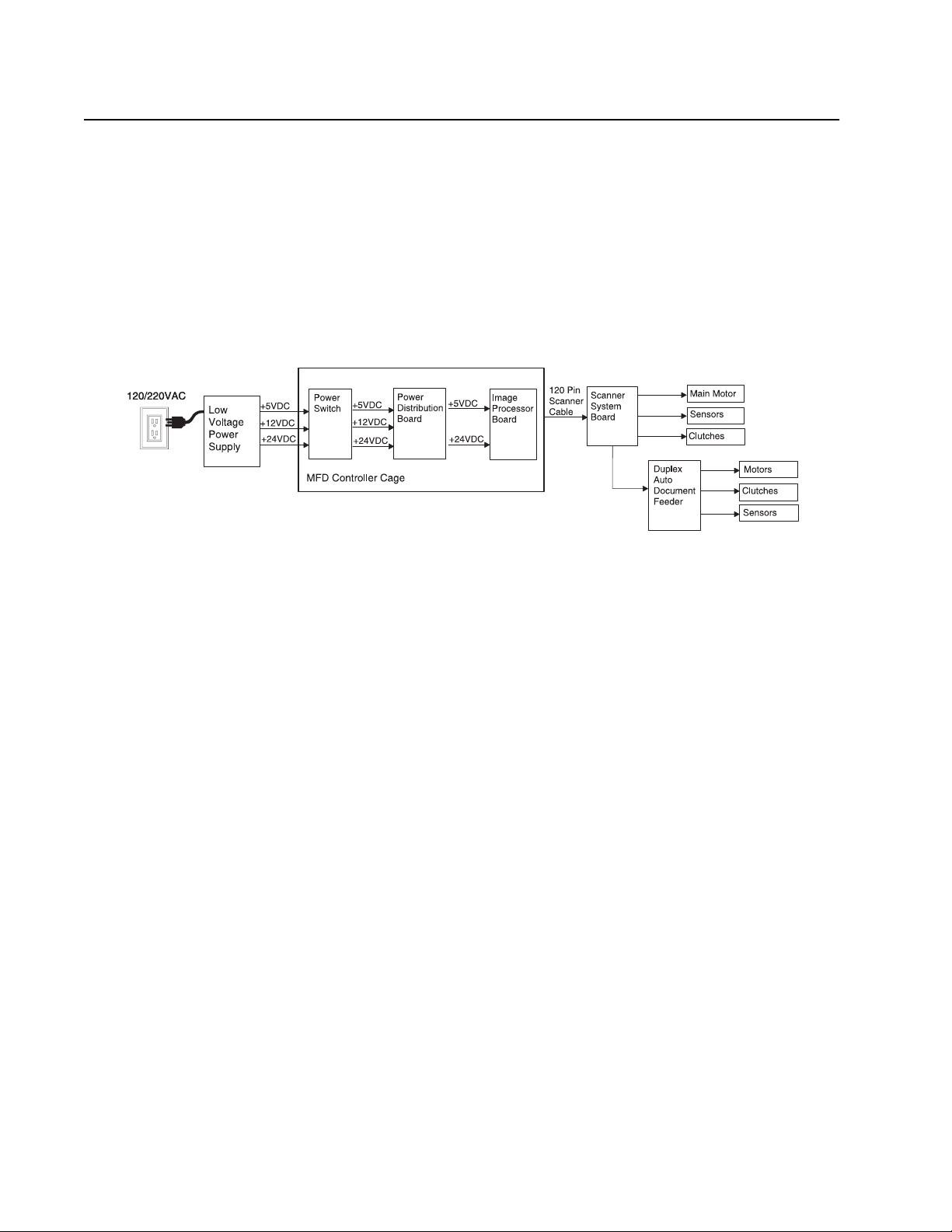
Duplex Auto Document Feeder (DADF) Power Principles of Operation
The power cord carries AC line voltage to the external low voltage power supply (LVPS).
The LVPS converts the 120/220VAC to regulated +5VDC, +12VDC, and +24VDC
voltages. The LVPS sends these voltages to the main power switch in the Multifunction
Device (MFD) controller cage. The voltage is then sent to the power distribution board.
The +5VDC and +24VDC voltages are sent through the image processing board and onto
the scanner through the 120 pin scanner cable. The voltage travels from the scanner
cable into the scanner system board where it passes onto the DADF.
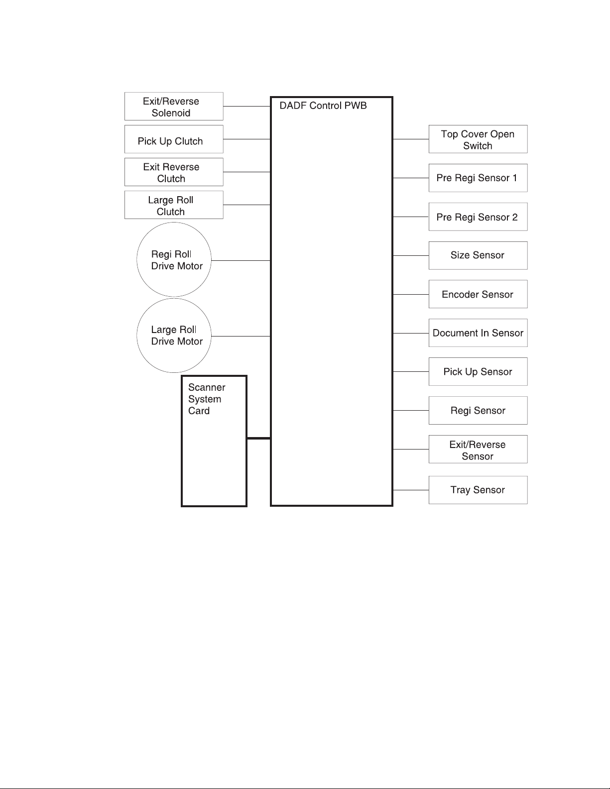
DADF Control
The DADF control card provides the logic and information processing that is necessary
for the DADF to function. Every electrical component within the DADF is connected to the
control card. Sensors in the DADF send status information to the control card. The control
card processes that information, shares it with the MFD controller cage, and compares it
to timing tables stored in ROM. Acting on the results of the processing, the control card
sends commands to the various DADF components
.
1-4 Service Manual
Page 15
4036-501
General Information 1-5
Page 16
4036-501
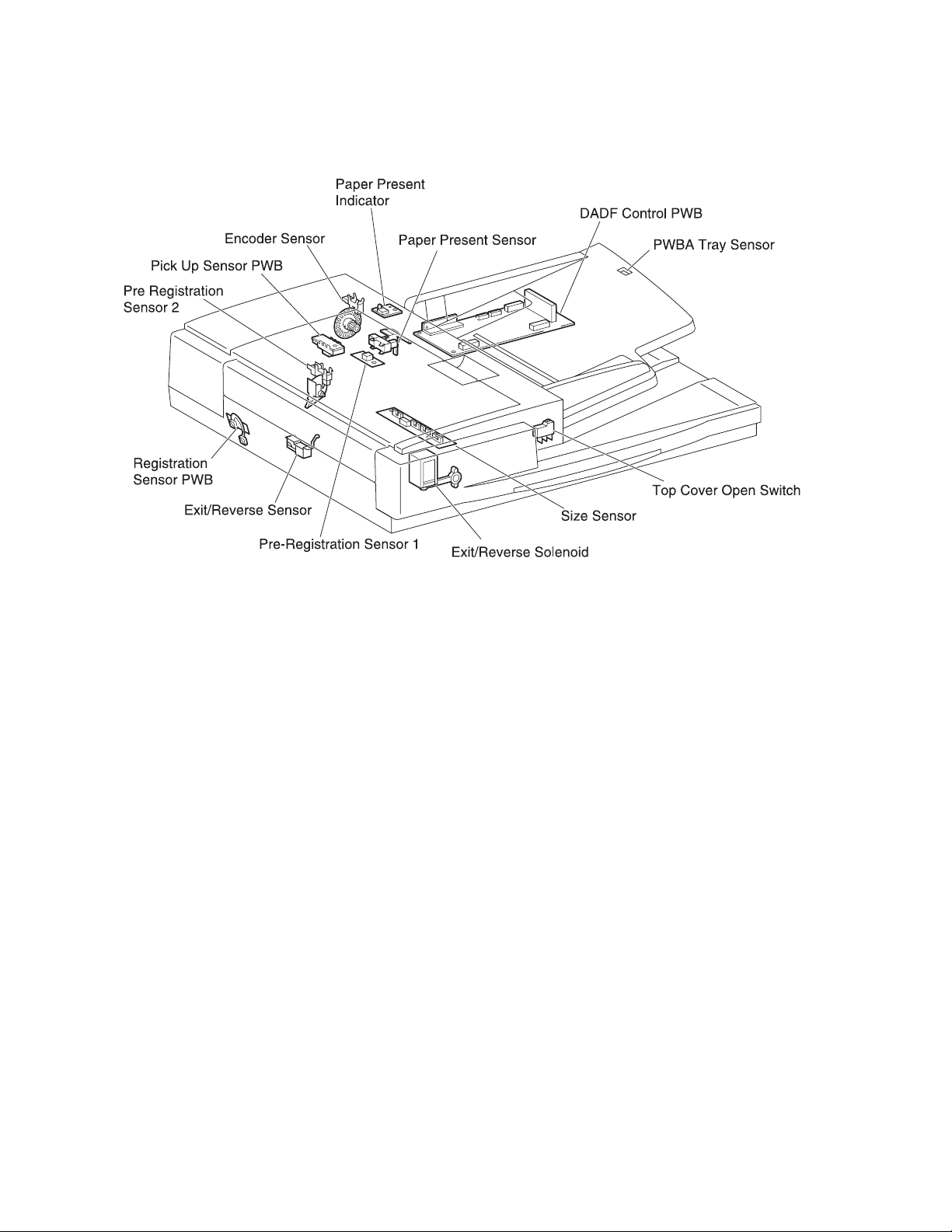
DADF Control Components
• DADF Control Card
The card controls all DADF functions, executes commands sent from the MFD
controller cage, and sends information back to the MFD controller cage.
• Top Cover Open Switch
The switch detects the jam access door assembly in the DADF is either opened or
closed.
• Pre-registration Sensor 1
This sensor detects top of paper and sends a signal for making the paper standby
just before the registration roll.
• Pre-registration Sensor 2
This sensor detects top of paper and sends a signal for making the paper standby
just before the large roll.
• Size Sensor
The sensor detects paper size. The passing paper uses three actuators on the size
sensor card and turns them on and off respectively. The originated signal is
transmitted to the MCU card.
• Encoder Sensor
The sensor detects the number of registration roll drive motor rotations.
• Paper Present Sensor
This sensor detects the paper loaded in the DADF.
• Pick Up Sensor
The sensor detects the existence of paper. This sensor utilizes a timing control of the
paper conveyance as well as analyzes and recognizes the length of paper.
1-6 Service Manual
Page 17

4036-501
• Registration Sensor
This sensor detects top of paper. The sensor uses the on/off control of the large roll
clutch to match up the timing of paper scanning with the timing of paper convey ance.
• Exit/Reverse Sensor
The sensor detects the paper passing it. This sensor also uses a timing control of
the paper conveyance.
• PWBA Tray Sensor
The tray sensor detects paper length set on the tray as being longer than the
specified length.
General Information 1-7
Page 18
4036-501
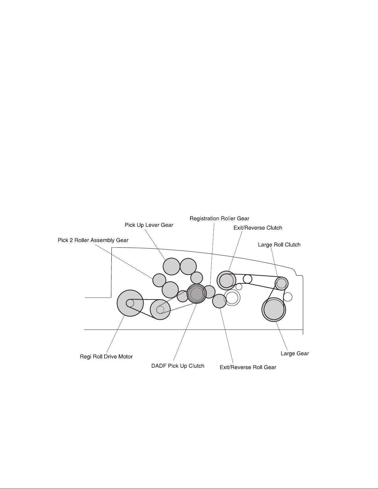
Mechanical Drive
Mechanical drive describes both the rotation of the motor and the action of the gears,
belts, and clutches that are used to transmit and control drive to the various components
throughout the DADF. The major purpose of the drive is to provide the dynamic energy
required for the paper conveyance throughout the DADF.
The registration roll drive motor provides the rotation power with the center gear of the
frame assembly through the belt (6 mm). The center gear of the frame assembly delivers
the rotation power to the gear (23T/48T) through the belt (6 mm). With the rotation of the
gear (23T/48T), the rotation power is distributed to the gears of the registration roll gear
and the pick 2 roller assembly respectively. The DADF pick up clutch distributes the drive
power to the pick up gear when activated, and then the power is delivered to the roller
engagement shaft assembly.
The DADF large roll drive assembly provides the rotation power with the each gear of the
large roll drive motor assembly through the belt (6 mm) and the belt (4 mm). The drive
power is delivered to the pulley 1 through the belt (6 mm) when the DADF large roll clutch
is actuated, and also to the large gear through the belt (6 mm). The further drive power is
delivered to the gear of the exit/reverse roll through the belt (4 mm) when the exit/ reverse
clutch is actuated.
1-8 Service Manual
Page 19

4036-501
DADF Mechanical Drive Components
The DADF mechanical drive is one major component, with numerous belts, pulleys, and
clutches that transmit drive to the various DADF transport rolls.
• DADF Registration Roll Drive Motor
There is +24VDC on the registration roll drive motor. This motor is part of the DADF
registration roll drive motor assembly.
• DADF Main Drive Motor
There is +24VDC on the step motor. This motor provides drive power to the DADF
main drive motor assembly.
• Pick Up Clutch
The clutch delivers drive power from the roller engagement shaft to the gears.
• Exit/Reverse Clutch
The clutch delivers drive power from the main drive motor to the exit/reverse roll.
• Large Roll Clutch
The clutch delivers drive power from the main drive motor to the large roll.
General Information 1-9
Page 20

4036-501
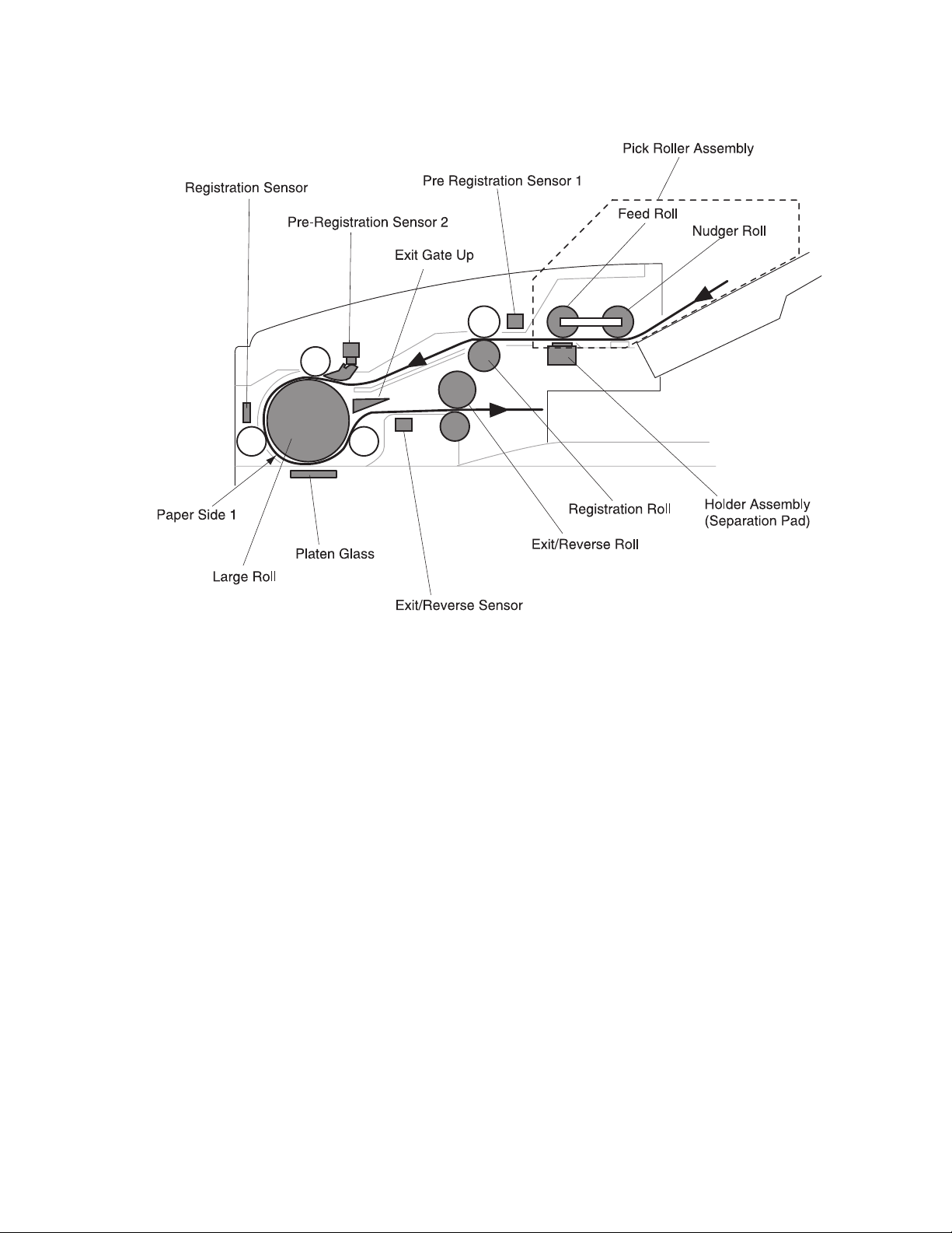
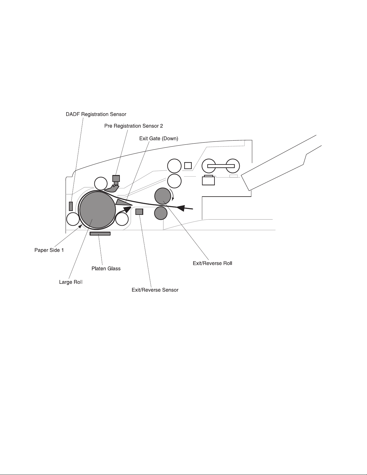
DADF Paper Path
The DADF moves the paper along the paper path using a combination of rolls, solenoids,
clutches and gears. The DADF adjusts the scanning timing to the specified paper
movement speed and fixing the cartridges of the scanner at the DADF position. The
DADF also allows the scanner to scan page 2 of the paper following page 1 using the
gate change mechanism of the duplex function.
1. Simplex Paper Path
• The rotation of the nudger roll, moves the paper on the DADF tray to the feed
roll.
• The paper moves to the registration roll by the rotation of the feed roll.
• When the pre–registration sensor 1, located just in front of the registration roll,
detects the passing of the top of the paper, the paper movement is interrupted
for the specified time to synchronize with the paper feed timing.
• The paper restarts toward the registration roll.
• After passing on the DADF upper paper guide, the top of the paper reaches and
actuates the paper present sensor of the pre-registration sensor.
• At the position just in front of the large roll, the paper movement is interrupted
again for the specified time to synchronize with the paper feed timing.
• The paper is moved to the DADF platen glass by rotation of the large roll.
• Along the way, the DADF registration sensor card interrupts the movement for
the specified time to synchronize with the scanning timing of the scanner.
• The sensor restarts to move the paper to the platen glass by the rotation of the
large roll.
• The image of the paper is scanned at the platen glass.
• After scanning, the paper passes the gate through the lower path and is moved
to the exit/reverse roll.
• The rotation of the exit/reverse roll discharges the paper onto the DADF output
tray.
1-10 Service Manual
Page 21
4036-501
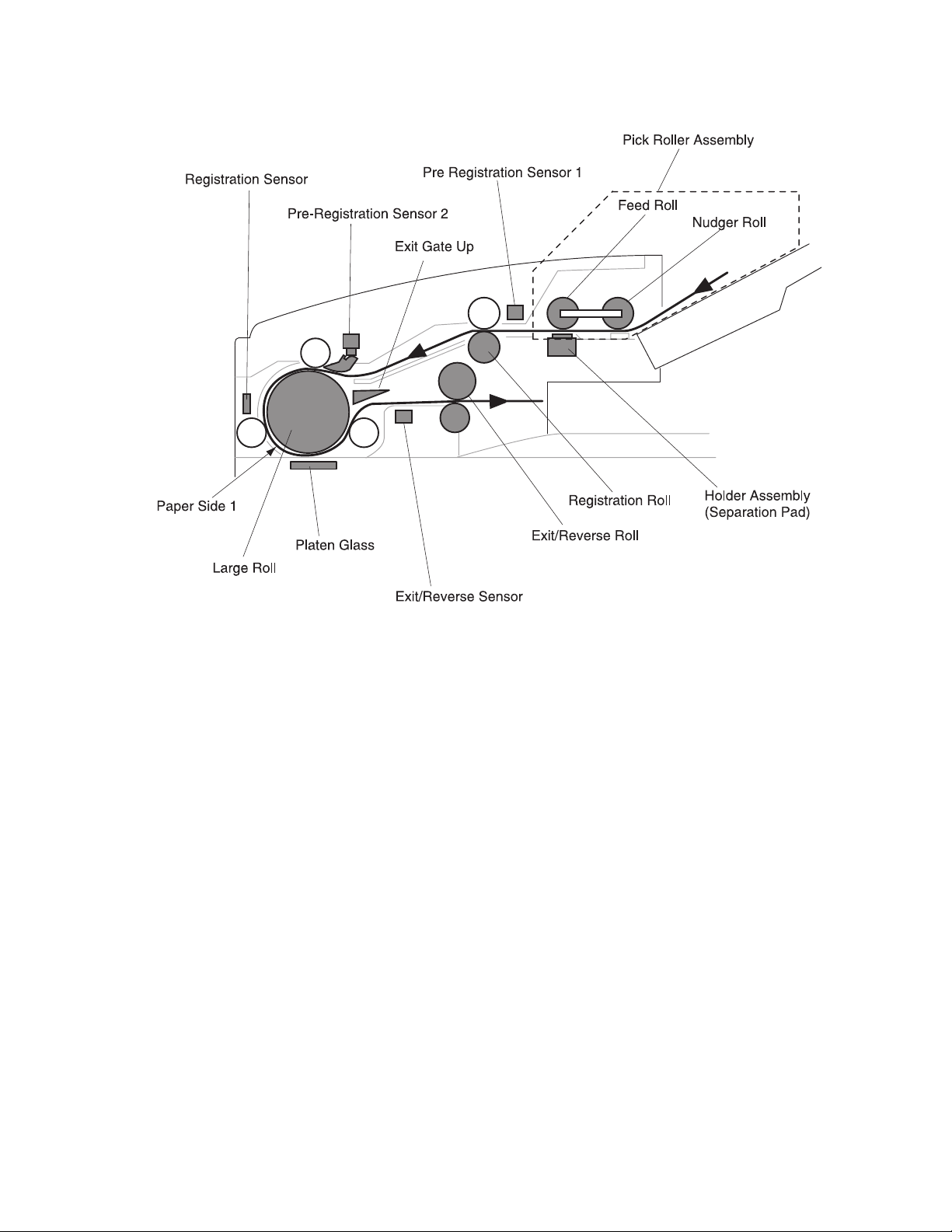
2. Duplex Paper Pa th
Note: The duplex paper path may be able to utilize two operational patterns due to its
mechanical configuration design. Those patterns are described in this section.
General Information 1-11
Page 22

4036-501
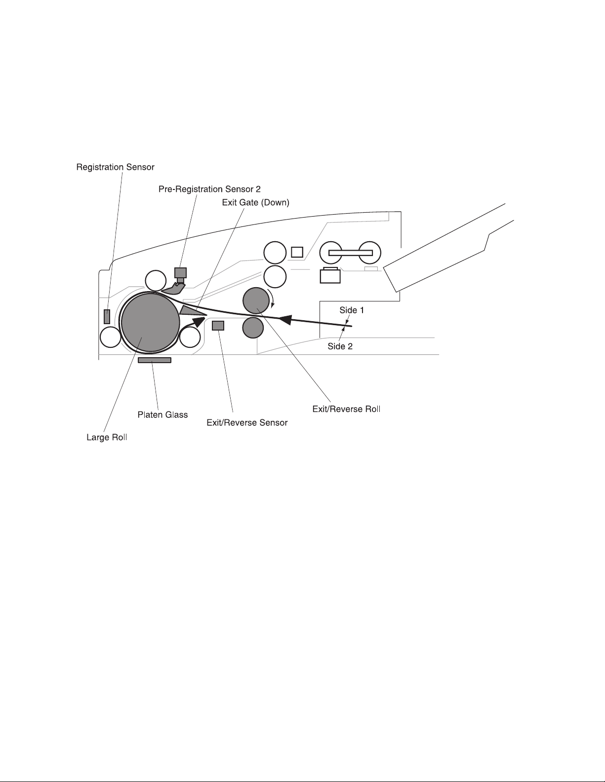
Operational Pattern 1
Step 1: Scan of side 1
• The rotation of the nudger roll moves the paper on the DADF tray to the feed
roll.
• The paper moves to the registration roll by the rotation of the feed roll and the
pad in the DADF individual separator pad.
• When the pre-registration sensor 1, located just in front of the registration roll,
detects the passing of the top of the paper, the paper movement is interrupted
for the specified time to synchronize with the paper feed timing.
• The paper restarts toward the registration roll.
• After passing the DADF upper paper guide, the top of the paper reaches and
actuates the paper present sensor flag of the pre–registration sensor 2.
• At the position just in front of the large roll, the paper movement is interrupted
again for the specified time to synchronize with the paper feed timing.
• The paper is moved to the DADF platen glass by rotation of the large roll.
• The DADF registration sensor card interrupts the movement for the specified
time to synchronize with the scanning timing of the scanner.
• The scanner restarts to move the paper to the platen glass by rotation of the
large roll. Utilizing the combined mechanism of the large roll rotation and the
scanner full rate carriage, side 1 of the paper is scanned.
• After scanning, the paper passes the gate through the lower path and moves to
the exit/reverse roll.
• Along the way, the timing of the exit/reverse sensor detects the pass of the top
of the paper.
• The paper is stopped by the exit/reverse roll and the reverse roll.
• The paper movement is stopped at the time when the end of the paper passes
on the exit/reverse sensor.
1-12 Service Manual
Page 23
4036-501
General Information 1-13
Page 24

4036-501
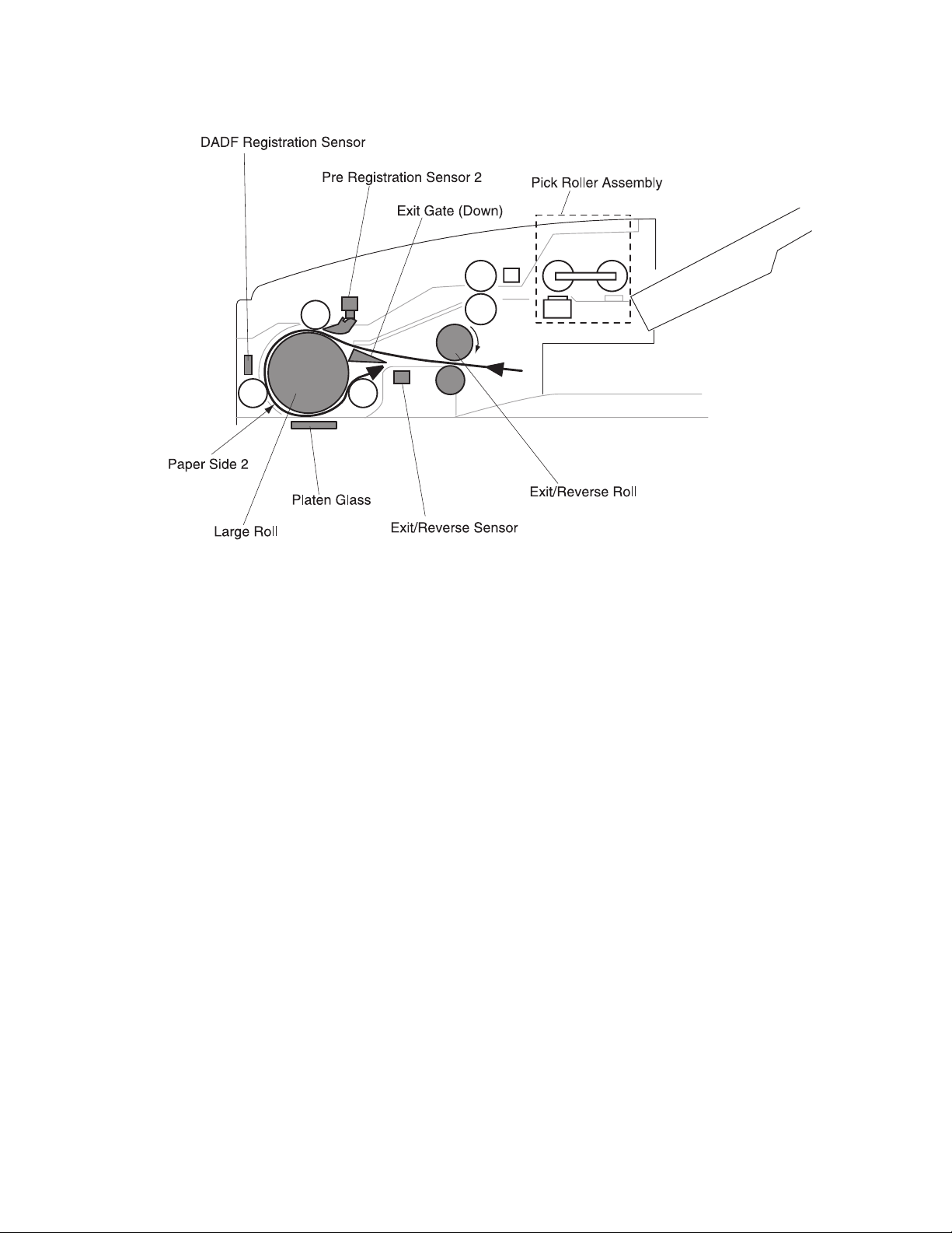
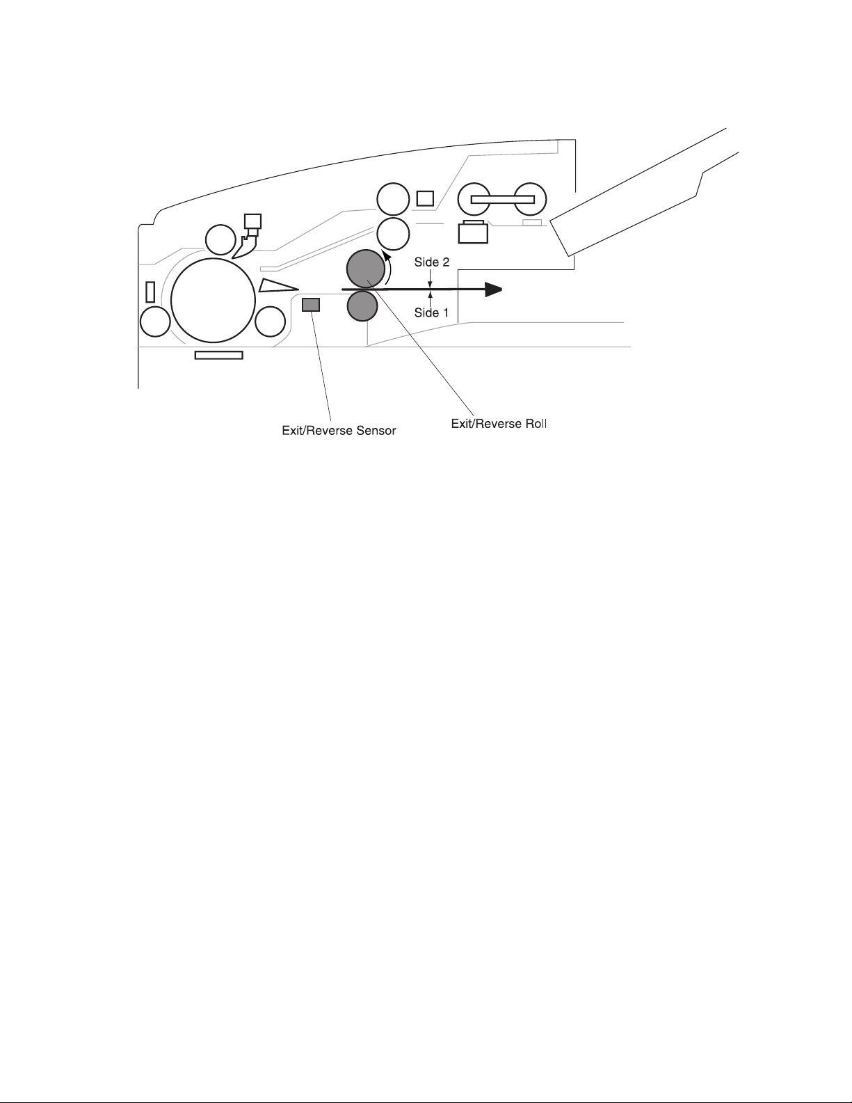
Step 2: Scan of side 2
• The paper is re–fed to the large roll by the counterclockwise rotation of the
exit/reverse roll.
• After the paper passes the gate through the upper path and at the timing when
the top of the paper actuates the paper present sensor flag of the pre–
registration sensor 2, the movement is interrupted for the specified time to
synchronize the paper feed timing and then restarted.
• The paper is moved toward the DADF platen glass.
• The paper it is interrupted to synchronize the feed timing with the scanning
timing of the scanner by the command signal sent from the DADF registration
sensor card.
• Paper is conveyed on to the platen glass by the rotation of the large roll, and
side 2 of the paper is scanned at the platen glass.
• After scanning, paper is moved toward the exit/reverse roll passing the gate
through its lower path.
• Paper movement is interrupted for a specified time when the end of the paper
passes on the exit/reverse sensor.
1-14 Service Manual
Page 25
4036-501
General Information 1-15
Page 26
4036-501
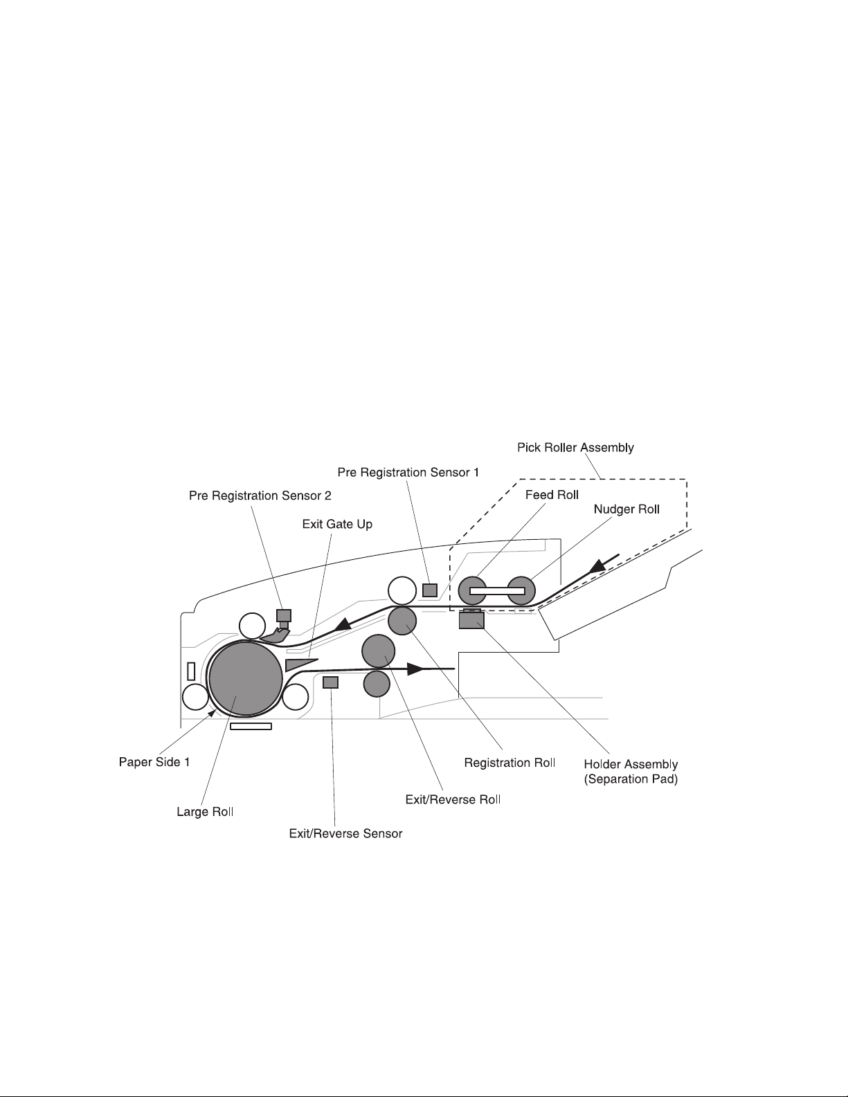
Step 3: High speed reverse rotation
• The paper is re–fed to the large roll by the counterclockwise rotation of the
exit/reverse roll.
• After passing over the upper side of the exit gate, the paper actuates the pre-
registration sensor #2. Movement of the paper is then interrupted for a specific
amount of time to synchronize paper feed timing.
1-16 Service Manual
• The paper moves toward the DADF platen glass. The rotation of the
exit/reverse roll stops.
• The paper moves toward the exit/reverse roll by the rotation of the large roll
passing the gate through the lower path.
• Passing the exit/reverse sensor, paper discharges to the DADF output tray by
the rotation of the exit/reverse roll.
Page 27
4036-501
General Information 1-17
Page 28
4036-501
Operational Pattern 2
Step 1: High speed paper feed
• The rotation of the nudger roll causes the paper on the DADF tray to feed into
the feed roll.
• A sheet of paper moves to the registration roll by the rotation of the feed roll.
When the pre-registration sensor 1, located just in front of the registration roll,
detects the passing the top of the paper, the paper movement is interrupted for
the specified time to synchronize with the paper feed timing.
• After the timing adjustment, the paper restarts toward the registration roll.
• After passing the chute, the paper moves by the rotation of the large roll
through the lower path of the gate toward the exit/reverse roll.
• When the exit/reverse sensor detects the passing of the top of the paper, the
paper is nipped by the exit/reverse roll.
• The paper movement is interrupted for a specified time when the end of the
paper passes to the exit/reverse sensor.
1-18 Service Manual
Page 29
4036-501
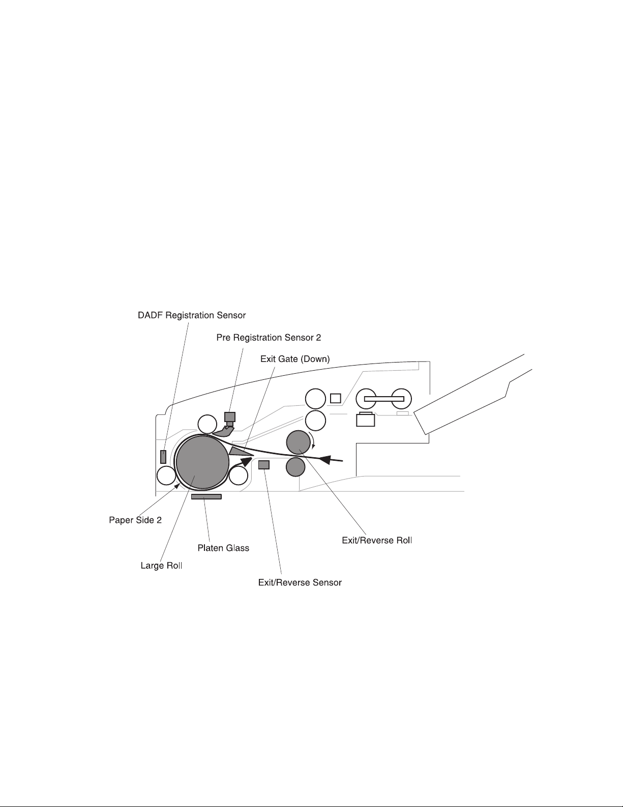
Step 2: Scan of side 2
• The paper is re–fed to the large roll by the counterclockwise rotation of the
exit/reverse roll.
• After passing over the upper side of the exit gate, the paper actuates the pre-
registration sensor #2. Movement of the paper is then interrupted for a specific
amount of time to synchronize paper feed timing.
• The paper moves toward the DADF platen glass. The paper is interrupted to
synchronize the feed timing with the scanning timing of the scanner by the
command signal sent from the DADF registration sensor card.
• The paper moves to the platen glass by the rotation of the large roll. Side 2 of
the paper is scanned at the platen glass.
• After scanning, the paper moves toward the exit/reverse roll passing the gate
through the lower path. The paper is nipped by the exit/reverse roll.
• The paper movement is interrupted for a specified time when the end of paper
passes on the exit/reverse sensor.
General Information 1-19
Page 30
4036-501
Step 3: Scan of side 1
• The paper is re–fed into the large roll by the CW rotation of the exit/reverse roll.
• After passing over the upper side of the exit gate, the paper actuates the pre-
registration sensor #2. Movement of the paper is then interrupted for a specific
amount of time to synchronize paper feed timing.
1-20 Service Manual
Page 31

4036-501
• The paper moves toward the DADF platen glass. The movement is interrupted
for the specified time by the DADF registration sensor card in order to
synchronize the paper feed timing with the scanning time.
• The paper is restarted toward the platen glass by the rotation of the large roll.
The image of side 1 is scanned at the platen glass.
• The paper moves toward the exit/reverse roll by the rotation of the large roll
passing the gate through the lower path.
• The paper discharges to the DADF output tray by the rotation of the exit/reverse
roll.
General Information 1-21
Page 32

4036-501
DADF Paper Path Components
The DADF paper path is made up of transport rolls and paper sensors.
• Nudger Roll (subassembly of pick roller assembly)
The roll moves paper toward the feed roll utilizing a combination of mechanisms
between the rotation of the roll and the friction of the separation pad.
• Feed Roll (subassembly of pick roller assembly)
The roll moves a sheet of paper toward the registration roll utilizing a combination of
mechanisms between the rotation of the roll and the friction of the separation pad.
• Registration Roll
The roll moves paper toward the large roll by its rotation, after the skew correction.
• Large Roll
The roll moves paper, by its rotation, toward the platen glass of the scanner for
scanning, and then moves toward the exit/reverse roll.
• Exit/Reverse Roll
The roll moves printed papers to the tray or turns over and sends the paper in the
direction of the large roll to duplex.
• Exit/Reverse Solenoid
This solenoid separates the reverse roll from the upper exit roll.
1-22 Service Manual
Page 33

4036-501
Scanner Principles of Operation
Scanner Power
The power cord carries AC line voltage to the external low voltage power supply (LVPS).
The L VPS conv erts the 120/220VAC to regulated 5VDC, +12VDC, and +24VDC voltages.
The LVPS sends these voltages to the main power switch in the Multifunction Device
(MFD) controller cage. The voltage is then sent to the power distribution board. The
+5VDC and +24VDC voltages are sent through the image processing board and onto the
scanner through the 120 pin scanner cable. The voltage travels from the scanner cable
into the scanner system board where it uses these voltages to run internal logic sensors,
clutches, and the main motor assembly.
General Information 1-23
Page 34

4036-501
Scanner Control
The scanner system card provides the logic and information processing that is necessary
for the scanner to function. Every electrical component within the scanner is connected to
the scanner system card. Sensors in the scanner send status information to the system
card. The system card processes that information, shares it with the MFD controller cage,
and compares it to timing tables stored in ROM. Acting on the results of the processing,
the system card sends commands to the various scanner components; switching on/off
the motor and exposure lamp.
1-24 Service Manual
Page 35

4036-501
General Information 1-25
Page 36

4036-501
Scanner Control Components
• Scanner System Card
The card controls all scanner functions, executes commands sent from the MFD
box, and sends information back to the MFD box.
• Registration Sensor
The sensor detects the paper present sensor flag at the side of the carriage and is
used to detect carriage home position.
• Charged Couple Device (CCD) Card
The card transmits video data read by the CCD card lens to the scanner system
card.
• PS-Lamp
The lamp provides the electric power to light the exposure lamp.
• Scanner Motor Card
The card controls the rotation of the scanner motor.
1-26 Service Manual
Page 37

4036-501
General Information 1-27
Page 38

4036-501
Mechanical Drive
Mechanical drive describes both the rotation of the scanner motor assembly and the
action of the gears, belts, and pulley that are used to transmit and control drive to the
various components throughout the scanner. The purpose of the drive is to provide
energy for movement of the full and half rate carriages while maintaining the focus
distance to the CCD card lens.
1-28 Service Manual
Page 39

4036-501
Mechanical Drive Components
• Scanner Motor
The +24VDC motor provides the drive power to the timing pulley.
• Timing Pulley
A pulley which dampens rotational pulses from the scanner motor while providing
rotational energy to the drive shaft assembly.
• Scanner Cable Assemblies, Front And Rear
Cables which move the full rate carriage by rotation of the drive shaft assembly. The
cables also move the half rate carriage half the displacement of the full rate carriage.
• Half Rate Carriage
A component which transfers the optical image from the full rate carriage to the CCD
card lens using two mirrors.
• Full Rate Carriage
A component used for scanning the image of the paper on the platen glass by
turning on the exposure lamp and scanning the image through the mirror
combination.
General Information 1-29
Page 40

4036-501
Scanning Methods
1. Platen Mode
Scans the document placed on the platen glass by movement of the full rate
carriage. The half rate carriage moves at half the rate of the full rate carriage to
maintain the proper focal length from the document to the CCD card lens.
2. DADF Mode
Scans the document being fed through the DADF through the left side DADF
platen glass. The half and full rate carriages are in a fixed position during this
type of scan. Only the image projected through the left side DADF platen glass
is obtained.
1-30 Service Manual
Page 41

4036-501
2. Diagnostic Information
Start
CAUTION: Remove power from the scanner system before you connect or disconnect
any cable or electronic board or assembly for personal safety and to prevent damage to
the scanner system.
Warning: It is extremely important not to connect or disconnect the 120-pin scanner
cable to the MFD controller cage while the power is on as doing so greatly increases the
chance of damaging the Low Voltage Digital Signaling devices in the image processor
card and user interface cards.
Use the service error codes and service checks in this chapter to determine the
corrective action necessary to repair a malfunctioning scanner system.
Service error codes for the printer attached to this scanner system can be viewed on the
printer's operator panel display. Refer to the printer's service manual for appropriate
repair actions.
The service error codes for the scanner system are divided into two main categories:
Scanner errors and MFD errors.
Scanner errors detected by the MFD controller card are displayed to the user interface
panel. If an error is reported to the user interface, go to “Scanner Errors” on page 2-2 to
determine the corrective action necessary to perform the repair.
MFD errors detected by the MFD controller card are displayed to the user interface panel
along with an audible beep code and LED code visible on the MFD controller card. If the
malfunction is associated with the user interface panel (preventing error messages to be
displayed), the beep and LED codes can further assist the servicer in diagnosing the
problem.
During a full Power-On Self Test, a beep and LED code are generated if a malfunction is
detected. Refer to “MFD Controller Cage Errors” on page 2-4 to read the codes and
determine the corrective action necessary to perform the repair.
If a problem exists with the scanner system unrelated to any of the error codes, go to
“Symptom Tab les” on page 2-7 to troubleshoot the problem and determine appropriate
repair action.
Diagnostic Information 2-1
Page 42

4036-501
Scanner Errors
Scanner Errors refers to errors detected within the flatbed scanner and duplexing autodocument feeder (DADF). These errors are displayed on the user interface touch screen.
Error message displ ayed to user
interface
Main scanner board memory error Replace the main scanner board.
Scanner RAM R/W error Replace the main scanner board.
Scanner EEPROM broken Replace the main scanner board.
Scanner EEPROM R/W error Replace the main scanner board.
Scanner to MFD cage
framing/overrun/parity error
Scanner to MFD cage
BCC error
Scanner to MFD cage
No communication
Scanner to MFD cage
Communication not established
Carriage registration sensor not
cleared
Corrective action
Check the connection of the scanner
to MFD controller cage cable.
Replace if defective.
Check the connection of the scanner
to MFD controller cage cable.
Replace if defective.
Check the connection of the scanner
to MFD controller cage cable.
Replace if defective.
Check the connection of the scanner
to MFD controller cage cable.
Replace if defective.
Inspect/replace the registration sensor
in the scanner.
Carriage registration sensor failed Inspect/replace the registration sensor
Motor pulse gap between scan and
return
AGC fail Replace the flatbed lamp. If problem
AOC fail 1 Replace the flatbed lamp. If problem
AOC fail 2 Replace the flatbed lamp. If problem
Shading calibration write failed Replace the flatbed lamp. If problem
2-2 Service Manual
in the scanner.
Inspect/replace the scanner motor.
persists, replace the lamp power
inverter.
persists, replace the lamp power
inverter.
persists, replace the lamp power
inverter.
persists, replace the lamp power
inverter.
Page 43

4036-501
Error message displ ayed to user
interface
DADF motor failed Inspect/replace the registration motor
DADF pre-registration sensor 1 failed Inspect/replace the pre-registration
DADF pre-registration sensor 2 failed Inspect/replace the pre-registration
DADF registration sensor failed Inspect/replace the registration sensor
DADF exit sensor failed Inspect/replace the exit sensor in the
DADF memory error Replace the DADF controller card
DADF EEPROM R/W error Replace the DADF controller card
Scanner to DADF
initial communication error
Scanner to DADF
framing/overrun/parity error
Corrective action
in the DADF.
sensor 1 in the DADF.
sensor 2 in the DADF.
in the DADF.
DADF .
assembly.
assembly.
Check the connection of the scanner
to DADF cable. Replace if defective.
Check the connection of the scanner
to DADF cable. Replace if defective.
Scanner to DADF
BBC error
Scanner to DADF
no communication
Scanner to DADF
communication not established
Scanner software error This error occurs when the controller
Check the connection of the scanner
to DADF cable. Replace if defective.
Check the connection of the scanner
to DADF cable. Replace if defective.
Check the connection of the scanner
to DADF cable. Replace if defective.
card in the MFD cage receives
information from the scanner it doesn't
expect. Turn off the power to the
scanner system and restart. If the
problem persists, replace the main
scanner board in the flatbed scanner.
If the problem continues, replace the
image processor card in the MFD
controller cage.
Diagnostic Information 2-3
Page 44

4036-501
MFD Controller Cage Errors
MFD controller cage errors are errors detected by the MFD controller card within the MFD
cage pertaining to electronic cards associated within the cage. All errors are posted to the
user interface touch screen along with audible beep codes and LED codes (visible on the
lower left side of the MFD controller card). During the Power-On Self Test procedure,
errors detected cause a number of audible beeps to be produced three times. The
corresponding LED pattern continuously displays on the controller card until the system is
powered down. Use the following tables to read the beep/LED codes and follow the
recommended repair action.
There are two rows of four LEDs. The LEDs are visible with the MFD controller cage lid
removed. The LED pattern shown depicts which LEDs are illuminated in the two rows.
Use caution when removing the lid while the system is powered up.
Error
number
21 2 Modem not found Modem on the MFD
22 2 PCI Bus failure Replace the MFD
24 2 Serial Port failure Problem with TTY/
28 2 Problem with the CPU Replace the MFD
Number
of beeps
LED pattern
Error message
displayed to user
interface
Corrective action
controller card is not
found. Replace the
MFD controller board.
controller board.
Serial P ort. Replac e the
MFD controller board.
controller board.
2-4 Service Manual
Page 45

4036-501
Error
number
31 3 (No Hard Drive Found)
32 3 (Missing VM Linux)
34 3 Hard drive failure There was an error
Number
of beeps
LED pattern
Error message
displayed to user
interface
Note: Error code
message not displayed
on the user interface.
Only beep code and
LED patterns are
generated for this error.
Note: Error code
message not displayed
on the user interface.
Only beep code and
LED patterns are
generated for this error.
Corrective action
Check connections to
the hard disk drive and
associated cables for
continuity . Check power
going to the hard disk
drive. Replace the
power distribution card
if no power is present. If
power is present,
replace the hard disk
drive.
The Linux kernal is not
found. Replace or
reformat the hard disk
drive.
writing to the hard drive
or the Linux code is
corrupt. Replace or
reformat the hard disk
drive.
41 4 Scanner interface not
found
42 4 Scanner interface failed
self-diagnostics
51 5 (No memory)
Note: Error code
message not displayed
on the user interface.
Only beep code and
LED patterns are
generated for this error.
The scanner image
processing board was
not found. Check
connections to the
interface board. If
connections are good,
replace the image
processor board.
The image processor
board is defective.
Replace the image
processor board.
The memory DIMM was
not detected or non–
functional. Replace the
memory DIMM.
Diagnostic Information 2-5
Page 46

4036-501
Error
number
52 5 Not enough memory The memory DIMM was
61 6 Scanner
62 6 Scanner ADF failed The DADF on the
64 6 Scanner main unit failed The flatbed scanner
Number
of beeps
LED pattern
Error message
displayed to user
interface
communication fault
Corrective action
found, but not enough
memory is present.
Replace the memory
DIMM.
Check the connection
and condition of the
120 pin scanner cable.
Replace as necessary.
If problem persists ,
check scanner and
repair as necessary.
scanner failed. Check
connection of the DADF
cable to the scanner.
Repair or replace the
DADF as necessary.
experienced a failure.
Repair or replace
scanner as necessary.
71 7 User interface failure A proble m was detect ed
with the user interface.
Check the connection
of the 120 pin scanner
cable and user interface
cables. If cables are
okay, replace the user
interface. If problem
persists, replace MFD
controller board.
2-6 Service Manual
Page 47

4036-501
Symptom Tables
Power does not come on.
Cause Relevant unit Check method*
Unplugged from
outlet
AC power unplugged
at power supply
Power switch is off MFD controll er cage Visual check Turn the power
Power supply power
distribution board
connection failure
Power supply output
voltage failure
Power distribution
board failure
MFD controller board MFD controller board None If problem persists,
None Visual check Insert the AC plug
None Visual check Insert the AC cable
None Visual check Connect the
LVPS Tester check the
LVPS (+5V, +12V,
+24V, GND)
Power distribution
board
Te ster check
(+5V, GND)
Maintenance
method
into the outlet.
into power supply.
switch on.
connector.
Replace the power
supply.
Replace the failed
power distribution
board.
replace MFD
controller board.
Note: *= check method explains how to check the failed item. T
• he visual check can be made by physically observing the part or observing the
offline test display on the front panel.
• The tester check is made by checking the voltage levels of the relevant units.
• See “Connector Locations” on page 5-1 for more information.
Diagnostic Information 2-7
Page 48

4036-501
Strange sound generated (DADF)
Cause Relevant unit Check method
Paper setting failure Operation error Is the paper correctly
set in the upper
paper guide?
Paper failure Operation error Is the specified
paper used?
ADF pick roller
improperly ins tal le d
Motor assembly
failure
Pick roller assembly Visual check of pick
roller.
• DADF registra t i on
roll drive motor
assembly
Visual check or
motor rotation.
• DADF main drive
motor assembly
Gear failure DADF gear 1, 2, 2B,
3 or 4.
Main drive m otor
assembly
Dirt on carriage
guides
Main drive assembly Visual check Replace the motor.
None Visual check Clean the carriage
Visual check of gear
rotation.
Maintenance
method
Teach users to
properly position the
paper.
None
Re-install pick roller
assembly.
Replace the failure
motor assembly.
Replace the failing
gear.
guides with isopropyl
alcohol.
2-8 Service Manual
Page 49

4036-501
Frequent paper jam, double feed or skew
Cause Relevant unit Check method
Paper setting failure Operation error Is the paper correctly
set in the upper
paper guide?
Paper failure Operation error Is the specified
paper used?
Paper debris None Check for paper
fragments in paper
path.
DADF pick roller
failure
Separator pad
assembly failure
Improper registration
roller adjustment
ADF pick roller
assembly
Separator pad
assembly
Registration rollers Is paper skewing
Check the pick roller
assembly for dirt and
wear.
Check the pad for
wear and tear.
inside the DADF?
Maintenance
method
Teach users to
properly position the
paper.
None
Clean paper path of
dirt and debris.
Clean or replace the
pick roller assembly.
(See “Maintaining
Your Multifunction
Product (MFP)” on
page 6-1 for more
information.
Clean or replace the
separator pad
assembly.
Adjust for paper
skew. See “DADF
Assembly Paper
Skew Adjustment”
on page 4-4 for
more information.
Improper DADF
assembly height
adjustment
DADF hinge Is the paper jamming
at the flatbed-toDADF interface?
Adjust hinges. See
“DADF Assembly
Height Adjustment”
on page 4-3 for
more information.
Diagnostic Information 2-9
Page 50

4036-501
Image unclea r
Cause Relevant unit Check method
Lamp too dark Lamp Visual check. Replace lamp.
Dirt on calibration
reference
Dirt on the mirrors Mirrors Visual check. Clean the mirrors
Dirt on the lens Lens Visual check. Clean the lens with
Flatbed platen glass Visual check of white
calibration strip on
underside of flatbed
glass.
Maintenance
method
Clean the flatbed
platen glass with
isopropyl alcohol.
with isopropyl
alcohol.
isopropyl alcohol.
Large jitter
Cause Relevant unit Check method
Main drive m otor
assembly connection
failure
None Visual check. Connect the
Maintenance
method
connector.
Main drive m otor
failure
Dynamic motor
damper failure
Main drive motor Visual check. Replace the motor.
Dynamic motor
damper
Visual check. Replace the dynamic
damper.
2-10 Service Manual
Page 51

4036-501
Image does not appear
Cause Relevant unit Check method
Image processor
board failure
Lamp power invertor
failure
Lamp failure Lamp Visual check. Replace the lamp.
CCD board-scanner
system board
connection failure
CCD board fails CCD board Visual check. Replace the CCD
Image processor
board
Lamp power invertor Visual check. Replace the lamp
None Visual check. Connect the
Visual check. Replace the image
Maintenance
method
processor board.
power invertor.
connector.
board.
Diagnostic Information 2-11
Page 52

4036-501
2-12 Service Manual
Page 53

4036-501
3. Diagnostic Aids
The Lexmark X7500 does not have any onboard diagnostic aids available.
Diagnostic Aids 3-1
Page 54

4036-501
3-2 Service Manual
Page 55

4036-501
4. DADF Repair Procedures
There are two sections containing the removal and replacement procedures for the major
parts within the duplex automatic document feeder (DADF) and the scanner.
Preparation
Before you begin any removal and replacement procedure:
1. Switch off the power to the entire scanner system.
2. Disconnect the AC power cord from the electrical outlet.
3. Ensure that all external devices are powered off and unplugged from wall outlets.
4. Wear an electrostatic discharge wrist strap to protect sensitive parts from damage.
Warning: Never disconnect a cable while the power is on. This can easily damage
sensitive circuit boards in the DADF, scanner, and MFD controller cage.
DADF Repair Procedures 4-1
Page 56

4036-501
Notations in the Removal Replacement text
Locations, such as R (right), assumes you are facing the scanner user interface panel.
• Arrows in an illustration show direction of movement when removing a component.
• Slashes in a part name indicate that numerous components share the same heading
and function. For example, “gears in/feed/out” refers to gear in, gear feed, and gear
out.
• The notation (P/Jx) indicates a plug and jack connection with the number being ‘x.’
• KL=clip
• E=E-ring
• S=screw
4-2 Service Manual
Page 57

4036-501
Adjustments
DADF Assembly Height Adjustment
Adjusts the height of the counterbalance to ensure correct paper feeds.
To ensure the adjustment is correct, make sure the two projections of the lower frame
touch the DADF platen glass slightly when the DADF assembly is shut under its own
weight.
Make sure there is no space between the DADF platen cushion and the platen glass
when the DADF asse mbly is shut under its own weight.
1. Loosen the nuts on both sides of the counterbalance.
2. Adjust the height and the slope of the DADF assembly by turning the set screws.
3. Turn the set screw in the direction of A.
The front side of the DADF is up and the rear side is down.
4. Turn the set screw in the direction of B.
The front side of the DADF is down and the rear side is up.
Note: After adjusting, tighten the nuts.
DADF Repair Procedures 4-3
Page 58

4036-501
DADF Assembly Paper Skew Adjustment
Moves the adjustment plate in
direction A.
4-4 Service Manual
Moves the adjustment plate in
direction B.
Page 59

4036-501
Adjusts the feeder which controls paper skew in the DADF assembly.
Note: Attach the adjustment plate by fitting its projection into the center of the feeder.
1. Move registration rollers 1 and 2 parallel to each other.
2. Loosen the screws in the adjustment plate and move the plate in the direction of A or
B to adjust the paper skew.
Note: After adjusting, tighten the screws.
DADF Repair Procedures 4-5
Page 60

4036-501
Adjusting the Position of Full Rate/Half Rate Carriages
1. Remove the flatbed center platen glass plate.
2. Loosen the two (2) screws that secure the full rate carriage.
3. Move the half rate carriage until it rests against the stopper.
Note: When the half rate carriage rests against the paper stop (2 pieces), a gap may be
generated on either the In or Out side stopper. Before you move to the next step, loosen
the two (2) screws on the rear pulley-capstan, and again tighten the screws with the
carriage pushed against the paper stop on either the In or Out side.
4. While the half rate carriage rests against the steppers, move the full rate carriage
until it rests against the right side frame.
5. Tighten the two (2) screws in the full rate carriage.
6. Mount the flatbed center platen glass plate.
4-6 Service Manual
Page 61

4036-501
DADF Repair Procedures 4-7
Page 62

4036-501
Configuring the MFD Controller Card
Anytime the MFD controller card is installed for the Lexmark X7500 and X4500, a
geography configuration must be performed in order for the fax modem to work properly.
Once the card is installed, follow the instructions below to set the appropriate fax modem
setting.
1. Turn on the power to the complete system.
Allow the system to go through the initial booting procedure.
2. Enter the SE menu by pressing **441.
3. Select Fax Setting on the main SE menu.
4. Select Modem Type from the fax setting menu.
5. Select the appropriate geography from the list.
6. Reboot the system.
4-8 Service Manual
Page 63

4036-501
DADF Repair Procedu res
DADF Assembly Removal
1. Remove the connector (P/J700), located at the rear side of the DADF assembly.
2. Open the DADF assembly.
3. Remove the two (2) thumbscrews.
4. Remove the black hinge loading plate from the right counterbalance.
5. Slide the DADF assembly toward the rear and lift up.
DADF Repair Procedures 4-9
Page 64

4036-501
Note: Follow the steps in the order shown to install the DADF.
4-10 Service Manual
Page 65

4036-501
DADF Front Cover, Handle, and Magnet Removal
1. Remove the DADF top cover. See “DADF Top Cover Removal” on page 4-18 for
more information.
2. Remove the two (2) screws in the DADF handle.
Note: The left screw, in the DADF handle, is shorter.
3. Remove the DADF handle.
4. Remove the two (2) screws in the DADF front cover.
5. Remove the DADF front cover.
6. Remove the screw in the DADF magnet.
7. Remove the DADF magnet.
Note: When reinstalling the DADF magnet, the white paint side must face out.
DADF Repair Procedures 4-11
Page 66

4036-501
DADF Cushion Removal
1. Open the DADF Assembly.
Note: The DADF cushion is stuck with two-sided tape.
2. After removing the DADF cushion, completely remove the two-sided tape remaining.
3. Remove the DADF cushion.
4-12 Service Manual
Page 67

4036-501
To replace the DADF cushtion:
1. Lay the DADF cushion, with seals facing up, on the platen glass of the scanner.
2. Peel the seals and align the DADF cushion to the rear of the scanner.
3. Lower the DADF assembly and push against the DADF cushion.
DADF Repair Procedures 4-13
Page 68

4036-501
DADF Exit/Reverse Solenoid Remo val
1. Remove the DADF top cover. See “DADF Top Cover Removal ” on page 4-18 for
more information.
2. Remove the DADF front cover. See “DADF Front Cover, Handle, and Magnet
Removal” on page 4-11 for more information.
3. Disconnect the two harnesses (P/J26).
4. Remove an E-ring.
5. Remove the screw.
6. Remove the exit/reverse solenoid.
4-14 Service Manual
Page 69

4036-501
DADF Input Tray Assembly Removal
1. Remove the DADF top cover. See “DADF Top Cover Removal” on page 4-18 for
more information.
2. Remove the DADF front cover. See “DADF Front Cover, Handle, and Magnet
Removal” on page 4-11 for more information.
3. Disconnect connector (P/J30).
4. Unclamp the input tray assembly harness from the frame.
5. Remove the screw and washer (toothed) from the ground wire.
6. Remove the screw from the retaining bracket.
7. Remove the retaining bracket.
8. Open the input tray assembly upward.
9. Remove the screw.
Note: This is a shorter screw.
10. Remove the plate.
11. Raise the front side of the input tray assembly, and pull out diagonally upward.
DADF Repair Procedures 4-15
Page 70

4036-501
DADF Jam Access Door Assembly Removal
1. Remove the DADF top cover. See “DADF Top Cover Removal ” on page 4-18 for
more information.
2. Remove the DADF front cover. See “DADF Front Cover, Handle, and Magnet
Removal” on page 4-11 for more information.
3. Disconnect (P/J13) and (P/J14).
4. Remove the screw from the jam access door lever.
5. Remove the screw from the jam access door assembly.
6. Push the door assembly toward the rear.
7. Raise the front side and pull out diagonally upward.
4-16 Service Manual
Page 71

4036-501
8. Remove six (6) screws in the lower cover of the door assembly as shown.
9. Remove the lower cover of the door assembly along with the jam access door lever.
When replacing the jam access door lever, align the key with the keyway in the lower
cover as shown.
DADF Repair Procedures 4-17
Page 72

4036-501
DADF Top Cover Removal
1. Open the jam access door assembly. See “DADF Jam Access Door Assembly
Removal” on page 4-16 for more information.
2. Remove four (4) screws in the DADF top cover.
3. Remove the top cover.
4-18 Service Manual
Page 73

4036-501
DADF Rear Cover Removal
1. Remove the DADF top cover. See “DADF Top Cover Removal” on page 4-18 for
more information.
2. Open the input tray cover assembly. See “DADF Input Tray Assembly Removal”
on page 4-15 for more information.
3. Loosen the two (2) screws.
4. Remove the rear cover.
DADF Repair Procedures 4-19
Page 74

4036-501
DADF Jam Door Open Switch Removal
1. Remove the DADF top cover. See “DADF Top Cover Removal ” on page 4-18 for
more information.
2. Remove the DADF front cover. See “DADF Front Cover, Handle, and Magnet
Removal” on page 4-11 for more information.
3. Disconnect (P/J32).
4. Unclamp the harness.
5. Remove the screw from the switch bracket.
6. Remove the switch.
4-20 Service Manual
Page 75

4036-501
Mylar Paper Guide Strip Removal
1. Remove the DADF top cover. See “DADF Top Cover Removal” on page 4-18 for
more information.
2. Remove the DADF front cover. See “DADF Front Cover, Handle, and Magnet
Removal” on page 4-11 for more information.
3. Remove the DADF rear cover . See “DADF Rear Cover Remov al” on page 4-19 for
more information.
4. Remove the eight (8) screws in the top half of the DADF assembly.
5. Release the cables from the two (2) harnesses.
6. Disconnect all the cables from the DADF controller card.
7. Remove the top half of the DADF assembly from the DADF base.
8. Fold the input tray assembly up.
9. Tilt the top half of the DADF assembly up on end.
10. Remove the screw in the paper stop.
11. Remove the paper bracket.
12. With the spring attached, rotate the paper stop and set aside.
13. Remove the mylar paper guide strip with a screwdriver.
DADF Repair Procedures 4-21
Page 76

4036-501
DADF Left and Right Hinge Removals
1. Remove the DADF top cover. See “DADF Top Cover Removal ” on page 4-18 for
more information.
2. Remove the DADF front cover. See “DADF Front Cover, Handle, and Magnet
Removal” on page 4-11 for more information.
3. Remove the DADF rear cover . See “DADF Rear Cover Remov al” on page 4-19 for
more information.
4. Remove the DADF main drive motor assembly. See “D ADF Main Drive Motor
Assembly Removal” on page 4-28 for more information.
5. Remove the two (2) screws in the DADF left hinge.
6. Remove the DADF left hinge.
4-22 Service Manual
Page 77

4036-501
7. Place the DADF assembly upside down.
8. Remove four (4) screws in the DADF right hinge.
9. Remove the DADF right hinge.
DADF Repair Procedures 4-23
Page 78

4036-501
DADF Controller Card Assembly Removal
1. Remove the DADF top cover. See “DADF Top Cover Removal ” on page 4-18 for
more information.
2. Remove the DADF rear cover . See “DADF Rear Cover Remov al” on page 4-19 for
more information.
3. Unlatch the cables from harnesses.
4. Disconnect (P/J2) on the DADF control card.
5. Disconnect (P/J3).
6. Disconnect (P/J4).
7. Disconnect (P/J6).
8. Disconnect (P/J7).
9. Disconnect (P/J8).
10. Disconnect (P/J9).
11. Remove the four (4) screws from the DADF controller card.
12. To remove the controller card from the bracket, remove the two (2) screws on each
side of the connector.
13. Remove the DADF controller card assembly.
4-24 Service Manual
Page 79

4036-501
DADF Repair Procedures 4-25
Page 80

4036-501
DADF Registration Roll Drive Motor Assembly Removal
1. Remove the DADF top cover. See “DADF Top Cover Removal ” on page 4-18 for
more information.
2. Remove the DADF front cover. See “DADF Front Cover, Handle, and Magnet
Removal” on page 4-11 for more information.
3. Remove the DADF rear cover . See “DADF Rear Cover Remov al” on page 4-19 for
more information.
4. Remove the KL clip from the rear roller engagement shaft assembly.
5. Slide and remove the bearing from the registration roll drive motor assembly.
6. Raise the rear side of the roller engagement shaft assembly, and move it toward the
left.
4-26 Service Manual
Page 81

4036-501
7. Disconnect the sensor connector (P/J25).
8. Disconnect the motor connector (P/J27).
9. Disconnect the clutch connector (P/J18).
10. Release all harnesses from the clamps on the DADF registration roll drive motor
assembly.
11. Remove three (3) screws from the DADF assembly to the DADF registration roll
drive motor assembly.
12. Remove the DADF registration roll drive motor assembly.
13. Remove the E-ring.
14. Remove the (DADF #2) gear.
15. Remove the (DADF #1) gear.
DADF Repair Procedures 4-27
Page 82

4036-501
DADF Main Drive Motor Assembly Removal
1. Remove the DADF top cover. See “DADF Top Cover Removal ” on page 4-18 for
more information.
2. Remove the DADF rear cover . See “DADF Rear Cover Remov al” on page 4-19 for
more information.
3. Release all harnesses from 3 clamps from the DADF main drive motor assembly.
4. Loosen the screw that adjusts the tension roller.
5. Remove the tension spring, and shift the tension roller toward the slackened belt.
6. Disconnect the registration sensor.
7. Thread the cable through the drive motor bracket.
8. Disconnect (P/J20).
9. Disconnect (P/J19).
10.Disconnect (P/J28).
11. Remove the screw (left side) from the ground wire.
12. Remove the screw (right side) from the ground wire.
13. Remove five (5) screws from the DADF assembly.
14. Remove the assembly.
4-28 Service Manual
Page 83

4036-501
When replacing the assembly:
1. Leave the drive motor belt off the gear until the bearing mates with the hole in the
frame.
2. Make sure the tension roller contacts the outside of the DADF main drive motor belt.
3. Mesh the teeth of the belt with the gear, and rotate the knob of the DADF main drive
motor assembly to engage the belt with the gear.
DADF Repair Procedures 4-29
Page 84

4036-501
DADF Separator Pad Assembly Removal
1. Open the input tray assembly.
2. Remove the two (2) screws from the separator pad assembly.
3. Pull out the assembly.
4-30 Service Manual
Page 85

4036-501
DADF Separator Pad Removal
1. Open the input tray cover. See “DADF Input Tray Assembly Removal” on
page 4-15 for more information.
2. Remove the two (2) screws from the assembly.
3. Slide the assembly to the right and out of the DADF assembly.
4. Remove the screw and slide the separator pad assembly toward the front, and raise
to remove it.
DADF Repair Procedures 4-31
Page 86

4036-501
DADF #1 and #2 Linkage Removals
1. Remove the DADF top cover. See “DADF Top Cover Removal ” on page 4-18 for
more information.
2. Remove the DADF front cover. See “DADF Front Cover, Handle, and Magnet
Removal” on page 4-11 for more informat ion.
3. Remove an E-ring from the DADF #1 linkage.
4. Pull out the linkage.
5. Remove an E-ring from the DADF #2 linkage.
6. Pull out the linkage.
4-32 Service Manual
Page 87

4036-501
Linkage Cover Removal
1. Remove the DADF top cover. See “DADF Top Cover Removal” on page 4-18 for
more information.
2. Remove the DADF front cover. See “DADF Front Cover, Handle, and Magnet
Removal” on page 4-11 for more informat ion.
3. Remove the screw from the frame.
4. Remove the cover.
DADF Repair Procedures 4-33
Page 88

4036-501
Paper Stop Spring and Paper Stop Removal
1. Remove the DADF top cover. See “DADF Top Cover Removal ” on page 4-18 for
more information.
2. Remove the DADF front cover. See “DADF Front Cover, Handle, and Magnet
Removal” on page 4-11 for more informat ion.
3. Remove the two (2) screws to drop down the DADF individual separator pad. See
“DADF Separator Pad Removal” on page 4-31 for more information.
4. Remove the linkage cover. See “Linkage Cover Removal” on page 4-33 for more
information.
5. Unhook the paper stop spring at both lower ends.
6. Remove the spring.
7. Fold the DADF input tray assembly up.
8. Remove the E-ring from the rear shaft of the paper stopper.
4-34 Service Manual
Page 89

4036-501
9. Slide the paper stop toward the rear until the front shaft of the stop is released from
the bearing.
10. Pull the paper stop out diagonally.
DADF Repair Procedures 4-35
Page 90

4036-501
DADF Roller Engagement Shaft Assembly Removal
1. Remove the DADF top cover. See “DADF Top Cover Removal ” on page 4-18 for
more information.
2. Remove the DADF front cover. See “DADF Front Cover, Handle, and Magnet
Removal” on page 4-11 for more informat ion.
3. Unhook the tension spring from the roller engagement shaft assembly.
4. Remove the KL clip from the front side of the shaft assembly to the bearing.
5. Remove the KL clip from the rear side of the shaft assembly to the bearing.
6. Slide the bearings on both sides of the shaft assembly toward the inside to release.
7. Remove the shaft assembly.
4-36 Service Manual
Page 91

4036-501
When replacing the shaft assembly, ensure it is oriented correctly.
DADF Repair Procedures 4-37
Page 92

4036-501
DADF Paper Present Sensor Removal
1. Remove the DADF top cover. See “DADF Top Cover Removal ” on page 4-18 for
more information.
2. Remove the screw from the DADF paper present sensor card and mylar cover.
3. Disconnect the paper present sensor connector (P/J15).
4. Remove the sensor.
4-38 Service Manual
Page 93

4036-501
DADF Paper Present Indicator Card Assembly Removal
1. Remove the DADF top cover. See “DADF Top Cover Removal” on page 4-18 for
more information.
2. Disconnect the connector (P/J29) from the DADF paper present indicator card.
3. Remove the screw.
4. Remove the indicator card.
DADF Repair Procedures 4-39
Page 94

4036-501
Paper Present Sensor Flag Removal
1. Remove the DADF top cover. See “DADF Top Cover Removal ” on page 4-18 for
more information.
2. Remove the DADF paper present indicator card assembly. See “DADF Paper
Present Indicator Card Assembly Removal” on page 4-39 for more information.
3. Remove the KL clip from the paper present sensor flag.
4. Raise the input tray assembly to 90° angle.
5. Slide the sensor toward the rear to remove.
4-40 Service Manual
Page 95

4036-501
DADF Pick Roller with Separator Pad Kit Assembly Removal
1. Remove the DADF top cover. See “DADF Top Cover Removal” on page 4-18 for
more information.
Note: Ensure the roller engagement shaft assembly pins are in the up position.
2. Remove two (2) KL clips from the shaft of the pick roller.
3. Release the two (2) springs.
4. Slide the rear bearing toward the inside.
5. Slightly lift the DADF pick roller assembly.
6. Slide the front bearing toward the inside until it releases from the frame.
7. Pull out the shaft toward the rear.
8. Lift the roller assembly from the left side and remove.
DADF Repair Procedures 4-41
Page 96

4036-501
Registration Sensor Removal
1. Remove the DADF top cover. See “DADF Top Cover Removal ” on page 4-18 for
more information.
2. Remove the DADF front cover. See “DADF Front Cover, Handle, and Magnet
Removal” on page 4-11 for more informat ion.
3. Remove the DADF jam access door assembly. See “DADF Jam Access Door
Assembly Removal” on page 4-16 for more information.
4. Disconnect the connector (P/J24) in the DADF registration sensor.
5. Release the harness from the three (3) clamps.
6. Remove the screw from the bracket.
7. Remove the bracket together with the DADF registration sensor.
4-42 Service Manual
Page 97

4036-501
DADF Gear #3 Bearing Removal
1. Remove the DADF top cover. See “DADF Top Cover Removal” on page 4-18 for
more information.
2. Remove the DADF rear cover. See “DADF Rear Cover Removal” on page 4-19 for
more information.
3. Remove the DADF main drive motor assembly. See “DADF Main Drive Motor
Assembly Removal” on page 4-28 for more information.
4. Remove the DADF left hinge. See “DADF Left and Right Hinge Removals” on
page 4-22 for more information.
5. Press the large roll from the upper side,
6. Remove the screw and a toothed washer from the DADF #3 gear.
7. Pull the gear off the shaft.
8. Pull the bearing off the shaft.
DADF Repair Procedures 4-43
Page 98

4036-501
Tension Roller Spring and Tension Roller Removal
1. Remove the DADF top cover. See “DADF Top Cover Removal ” on page 4-18 for
more information.
2. Remove the DADF rear cover. See “DADF Rear Cover Removal” on page 4-19 for
more information.
3. Unhook the tension roller spring.
4. Remove the spring.
5. Remove the two (2) screws from the tension roller.
6. Remove the roller.
4-44 Service Manual
Page 99

4036-501
DADF Upper Paper Guide Removal
1. Open the DADF jam access door assembly. See “DADF Jam Access Door
Assembly Removal” on page 4-16 for more information.
2. Open the DADF upper paper guide to a 90° angle.
3. Pull the front hook of the paper guide out of the stud.
4. Slide the rear hook of the paper guide, and pull it out of the stud.
DADF Repair Procedures 4-45
Page 100

4036-501
DADF #4 Gear Removal
1. Remove the DADF top cover. See “DADF Top Cover Removal ” on page 4-18 for
more information.
2. Open the DADF upper paper guide. See “DADF Upper Pap er G u i de R emov al ” on
page 4-45 for more information.
3. Remove the screw from the plate to the DADF assembly.
4. Remove the plate.
5. Remove the KL clip from the roller in the upper front side of the DADF assembly.
6. Slide the upper roller toward the front.
7. Remove the roller along with the bearing.
Note: Pass through an opening on the rear side of the DADF assembly between the
bearing and the gear.
4-46 Service Manual
 Loading...