

Page 1

• Table of Contents
• Start Diagnostics
• Safety and Notices
• Trademarks
Optra™ E
4026-0XX
• Index
Lexmark and Optra are trademarks of
Lexmark International, Inc., registered
in the United States and/or other
countries.
Page 2

4026-0XX
Third Edition (April 1997)
The following paragraph does not apply to the United Kingdom or any country
where such provisions are inconsistent with local law: LEXMARK
INTERNATIONAL, INC. PROVIDES THIS PUBLICATION “AS IS” WITHOUT
WARRANTYOFANYKIND,EITHER EXPRESS OR IMPLIED, INCLUDING, BUT
NOT LIMITED TO, THE IMPLIED WARRANTIES OF MERCHANTABILITY OR
FITNESS FOR A PARTICULAR PURPOSE. Some states do not allow disclaimer
of express or implied warranties in certain transactions, therefore, this statement
may not apply toyou.
This publication could include technical inaccuracies or typographical errors.
Changes are periodically made to the information herein; these changes will be
incorporated in later editions of the publication. Improvements or changes in the
products or the programs described in this publication may be made at any time.
Publications are not stocked at the address given below; requests for publications
should be made to your point of purchase.
Comments may be addressed to Lexmark International, Inc., D22A/035-3,
740 New Circle Road NW,Lexington, Kentucky40550, U.S.A. Lexmark may use
or distribute any of the information you supply in any way it believes appropriate
without incurring any obligation to you.
Lexmark and Optra are trademarks of Lexmark International, Inc., registered in the
United States and/or other countries.
Other trademarks are the property of their respective owners.
Copyright Lexmark International, Inc. 1995, 1997
All rights reserved.
UNITED STATES GOVERNMENT RESTRICTED RIGHTS
This software and documentation are provided with RESTRICTED RIGHTS. Use,
duplication or disclosure by the Government is subject to restrictions as set forth in
subparagraph (c)(1)(ii) of theRights in Technical Data and Computer Software
clause at DFARS 252.227-7013 and in applicable FAR provisions: Lexmark
International, Inc., Lexington, KY 40550.
Page 3

4026-0XX
Contents 1
NoticesandSafetyInformation ..........................vi
LaserNotice....................................... vi
SafetyInformation.................................. xvi
OzoneInformation................................. xix
Preface .............................................xx
GeneralInformation...................................1-1
Options.......................................... 1-1
Maintenance Approach.............................. 1-1
Tools Required For Service .......................... 1-1
Acronyms........................................ 1-2
DiagnosticInformation ................................2-1
Start............................................ 2-1
ServiceErrorCodes............................. 2-2
UserErrorMessageTable........................ 2-6
UserSecondaryErrorMessageTable............... 2-8
Power-OnSelfTest(POST)...................... 2-10
POSTSymptomTable.......................... 2-12
SymptomTable............................... 2-13
ServiceChecks................................... 2-15
ChargeBrushServiceCheck..................... 2-15
CoverInterlockServiceCheck.................... 2-16
D-RollAssemblyServiceCheck................... 2-16
ExitSensorServiceCheck....................... 2-17
FanServiceCheck............................. 2-17
ColdFuserServiceCheck....................... 2-18
HotFuserServiceCheck........................ 2-20
Input Sensor Service Check...................... 2-20
Low Voltage Power Supply Service Check . . . ....... 2-22
MainDriveMotorServiceCheck.................. 2-25
Operator Panel Service Check.................... 2-27
Optional Paper Tray Two Service Check............ 2-28
Paper Take-Up Solenoid Service Check ............ 2-32
ParallelPortServiceCheck...................... 2-34
Paper Feed Service Check ...................... 2-34
Paper Feed Frame Assembly Service Check . ....... 2-37
PrintQualityServiceCheck...................... 2-38
RegistrationServiceCheck...................... 2-44
TransferAssemblyServiceCheck................. 2-44
TransferCoronaServiceCheck................... 2-45
ROMSIMMServiceCheck ...................... 2-45
iii
Page 4

DiagnosticAids ......................................3-1
Power-OnSelfTest(Post)........................... 3-1
Diagnostic Tests . ................................. 3-3
Printer Diagnostic Test . . ........................ 3-3
Service Diagnostic Test Page ..................... 3-4
UserModePrintTestPage....................... 3-6
Paper Feed Timing ............................. 3-8
FuserOperation................................ 3-9
ConfigurationMode............................ 3-10
Configuration Mode Operator Panel Overlay . . . ..... 3-10
Operator Panel Configuration Mode Button Definition . 3-11
HexTrace................................... 3-12
RestoringFactoryDefaults...................... 3-13
RepairInformation....................................4-1
Handling ESD-Sensitive Parts........................ 4-1
Adjustment Procedures ............................. 4-2
PrintRegistrationAdjustment..................... 4-2
RemovalProcedures............................... 4-3
Screw Identification Table........................ 4-3
BoardCageRemoval........................... 4-4
CoverRemovals............................... 4-4
ControllerBoardRemoval........................ 4-5
D-RollRemoval................................ 4-6
EngineBoardRemoval.......................... 4-6
ExitSensorRemoval............................ 4-6
ExitSensorFlagRemoval........................ 4-6
Exit Paper Feed Roller Assembly Removal........... 4-7
FanRemoval.................................. 4-7
FuserLampRemoval........................... 4-7
FuserLowerFrameAssemblyRemoval............. 4-8
Fuser Upper Frame Assembly Removal ............. 4-8
Fuser Paper Separator Removal................... 4-8
HVPSBoardRemoval........................... 4-9
HVPSCoverRemoval........................... 4-9
LeftSidePlateRemoval......................... 4-9
LVPSRemoval............................... 4-10
MainDriveMotorRemoval...................... 4-10
MainDrive/PaperFeedGearsRemoval............ 4-10
Manual Paper Feed Guide Plate Removal .......... 4-10
Operator Panel Removal. ....................... 4-11
Paper Entry Sensor Removal .................... 4-11
Paper Entry Sensor Flag Removal . . .............. 4-11
Paper Feed Frame Assembly Removal............. 4-12
iv
Page 5

4026-0XX
Removal Procedures (continued)
Paper Feed Solenoid Removal . . . ................ 4-12
Paper Feed Input Tray Assembly Removal . . . ....... 4-12
Paper Lift Plate Assembly Removal................ 4-12
Paper Separator Removal ....................... 4-13
Printhead Removal............................. 4-13
Print Media Selection Lever Removal (06C/06F/071) . . 4-13
Second Paper Tray Option Connector Removal ...... 4-13
Thermal Fuse Removal (06A/06B/06D/06J/070) ...... 4-14
ThermostatRemoval(06C/06F/071)............... 4-14
ThermistorRemoval............................ 4-14
TransferUnitRemoval.......................... 4-14
ConnectorLocations ..................................5-1
Low Voltage Power Supply ....................... 5-1
High Voltage Power Supply ....................... 5-2
EngineBoard.................................. 5-3
SecondPaperTraySensorBoard(Option)........... 5-7
ControllerBoard................................ 5-7
Paper Exit Sensor ............................. 5-11
Paper Entry Sensor . . . ......................... 5-11
Paper Feed Solenoid . . ......................... 5-11
PartsCatalog ........................................6-1
HowToUseThisPartsCatalog....................... 6-1
Assembly1:Covers............................. 6-2
Assembly2:Frame ............................. 6-6
Assembly 3: Printhead. ......................... 6-12
Assembly 4: Paper Feed Input Tray................ 6-14
Assembly 5: Paper Feed Frame. . . ................ 6-16
Assembly6:Fuser............................. 6-18
Assembly7:Electronics......................... 6-22
Assembly8:TransferAssembly................... 6-26
Assembly 9: Option - Second Paper Drawer . . ....... 6-28
Assembly10:Options .......................... 6-34
Assembly 11: Miscellaneous ..................... 6-35
Index .............................................. X-1
v
Page 6

4026-0XX
Notices and Safety Information
Laser Notice
The printer is certified in the U.S. to conform to the requirements of
DHHS 21 CFR Subchapter J for Class I (1) laser products, and
elsewhere is certified as a Class I laser product conforming to the
requirements of IEC 825.
Class I laser products are not considered to be hazardous. The
printer contains internally a Class IIIb (3b) laser that is nominally a 5
milliwatt gallium arsenidelaser operating in the wavelengthregion of
770-795 nanometers. The laser system and printer are designed so
there is never any human access to laser radiation above a Class I
level during normal operation, user maintenance, or prescribed
service condition.
vi Service Manual
Page 7
4026-0XX
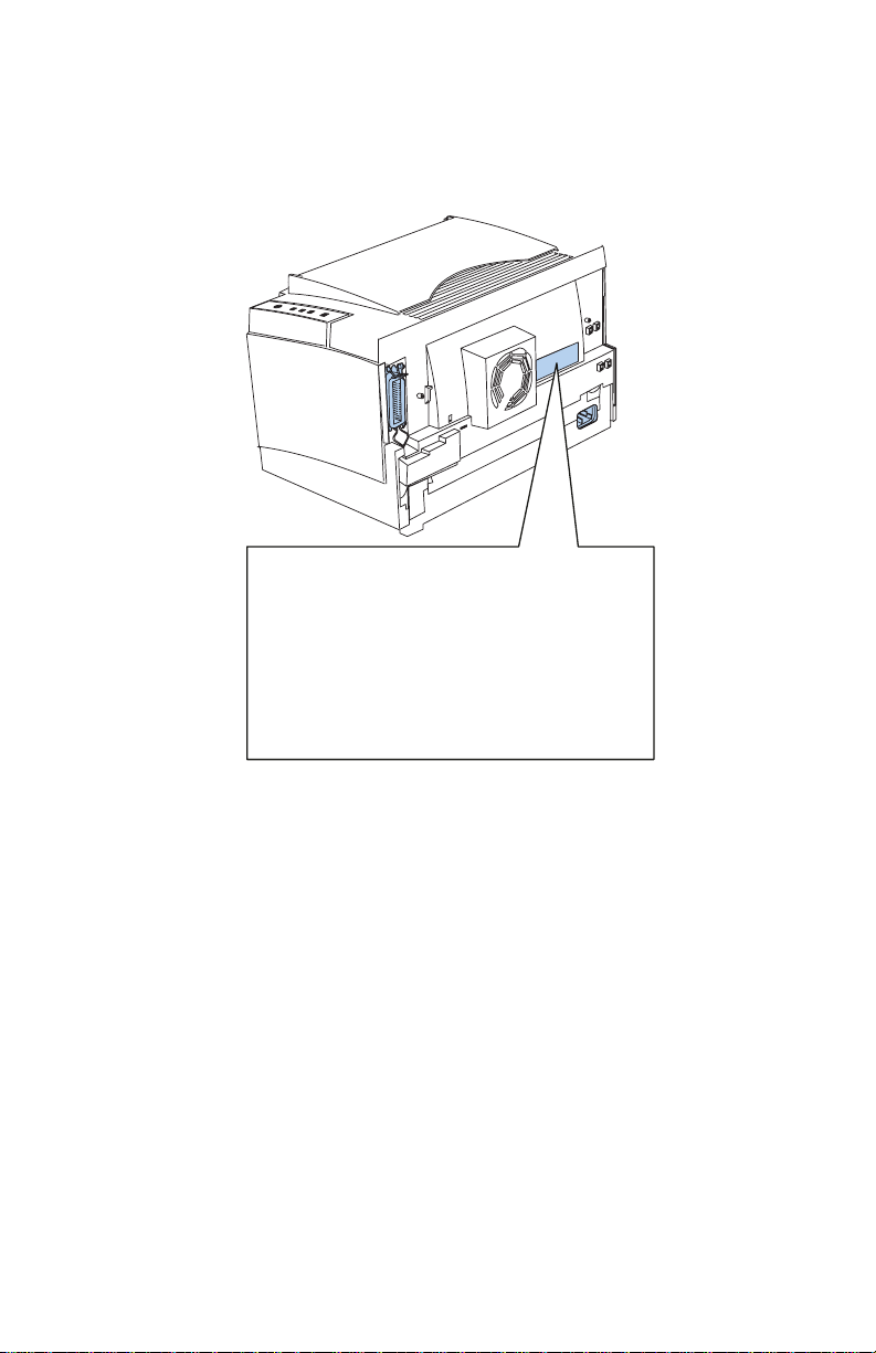
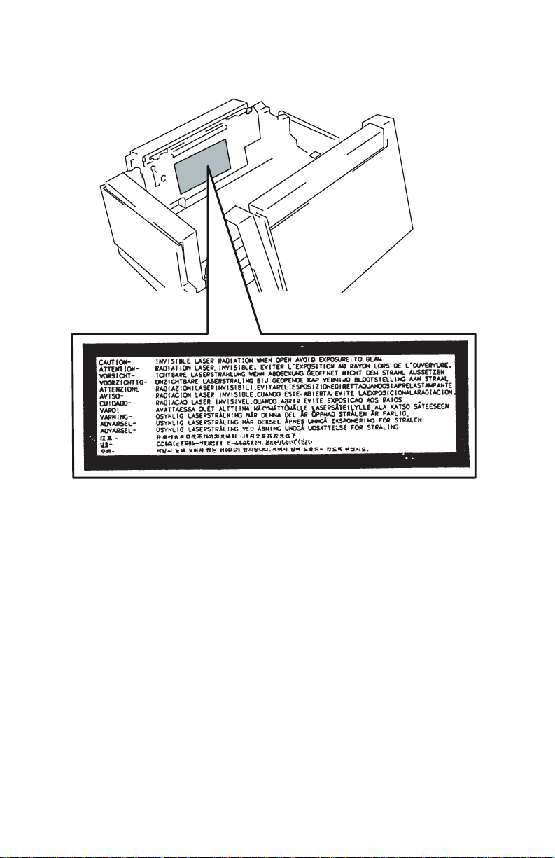
Laser product labels are located on the back of the printer and on
the printhead.
CLASS 1 LASER PRODUCT
LASER KLASSE1 NACH IEC825
LUOKAN 1 LASERLAITE
APPAREIL A LASER DE CLASSE1
TO IEC 825
Notices and Safety Information vii
Page 8
4026-0XX
viii Service Manual
Page 9

4026-0XX
Laser
Der Drucker erfüllt gemäß amtlicher Bestätigung der USA die
Anforderungen der Bestimmung DHHS (Department of Health and
Human Services) 21 CFR Teil J für Laserprodukte der Klasse I (1).
In anderen Ländern gilt der Drucker als Laserprodukt der Klasse I,
der die Anforderungen der IEC (International Electrotechnical
Commission) 825 gemäß amtlicher Bestätigung erfüllt.
Laserprodukte der Klasse I gelten als unschädlich. Im Inneren des
Druckers befindet sich ein Laser der Klasse IIIb (3b), bei dem es
sich um einen Galliumarsenlaser mit 5 Milliwatt handelt, der Wellen
der Länge 770-795 Nanometer ausstrahlt. Das Lasersystem und der
Drucker sind so konzipiert, daß im Normalbetrieb, bei der Wartung
durch den Benutzer oder bei ordnungsgemäßer Wartung durch den
KundendienstLaserbestrahlung, die die Klasse I übersteigen würde,
Menschen keinesfalls erreicht.
Avis relatif à l’utilisation de laser
Pour les Etats-Unis : cette imprimante est certifiée conforme aux
provisions DHHS 21 CFR alinéa J concernant les produits laser de
Classe I (1). Pour les autres pays : cette imprimante répond aux
normes IEC 825 relatives aux produits laser de Classe I.
Les produits laser de Classe I sont considérés comme des produits
non dangereux. Cette imprimante est équipée d’un laser de Classe
IIIb (3b) (arséniure de gallium d’une puissance nominale de 5
milliwatts) émettant sur des longueurs d’onde comprises entre 770
et 795 nanomètres. L’imprimante et son système laser sont conçus
pour impossible, dans des conditions normales d’utilisation,
d’entretien par l’utilisateur ou de révision, l’exposition à des
rayonnements laser supérieurs à des rayonnements de Classe I .
Notices and Safety Information ix
Page 10

4026-0XX
Avvertenze sui prodotti laser
Questa stampante è certificata negli S tati Uniti per essereconforme
ai requisiti del DHHS 21 CFR Sottocapitolo J per i prodotti laser di
classe 1 ed è certificata negli altri Paesi come prodotto laser di
classe 1 conforme ai requisiti della norma CEI 825.
I prodotti laser di classe non sono considerati pericolosi. La
stampante contiene al suo interno un laser di classe IIIb (3b)
all’arseniuro di gallio della potenza di 5mW che opera sulla
lunghezza d’onda compresa tra 770 e 795 nanometri. Il sistema
laser e la stampante sono stati progettati in modo tale che le
persone a contatto con la stampante, durante il normale
funzionamento, le operazioni di servizio o quelle di assistenza
tecnica, non ricevano radiazioni laser superiori al livello della classe
1..
Avisos sobre el láser
Se certifica que, en los EE.UU., esta impresora cumple los
requisitos para los productos láser de Clase I (1) establecidos en el
subcapítulo J de la norma CFR 21 del DHHS (Departamento de
Sanidad y Servicios) y, en los demás países, reúne todas las
condiciones expuestas en la norma IEC 825 para productos láser de
Clase I (1).
Los productos láser de Clase I no se consideran peligrosos. La
impresora contiene en su interior un láser de Clase IIIb (3b) de
arseniuro de galio de funcionamiento nominal a 5 milivatios en una
longitud de onda de 770 a 795 nanómetros. El sistema láser y la
impresora están diseñados de forma que ninguna persona pueda
verse afectada por ningún tipo de radiación láser superior al nivel de
la Clase I durante su uso normal, el mantenimiento realizado por el
usuario o cualquier otra situación de servicio técnico.
x Service Manual
Page 11

4026-0XX
Declaração sobre Laser
A impressora está certificada nos E.U.A. em conformidade com os
requisitos da regulamentação DHHS 21 CFR Subcapítulo J para a
Classe I (1) de produtos laser. Em outros locais, está certificada
como um produto laser da Classe I, em conformidade com os
requisitos da norma IEC 825.
Os produtos laser da Classe I não são considerados perigosos.
Internamente, a impressora contémum produto laser da ClasseIIIb
(3b), designado laser de arseneto de potássio, de 5 milliwatts
,operando numa faixa de comprimento de onda entre 770 e 795
nanómetros. O sistemaeaimpressoralaserforamconcebidosde
forma a nunca existir qualquer possiblidade de acesso humano a
radiação laser superior a um nível de Classe I durante a operação
normal, a manutenção feita pelo utilizador ou condições de
assistência prescritas.
Laserinformatie
De printer voldoet aan de eisen die gesteld worden aan een
laserprodukt van klasse I. Voor de Verenigde Staten zijn deze eisen
vastgelegd in DHHS 21 CFR Subchapter J, voor andere landen in
IEC 825.
Laserprodukten van klasse I worden niet als ongevaarlijk
aangemerkt. De printer is voorzien van een laser van klasse IIIb
(3b), dat wil zeggen een gallium arsenide-laser van 5 milliwatt met
een golflengte van 770-795 nanometer. Het lasergedeelte en de
printer zijn zo ontworpen dat bij normaal gebruik, bij onderhoud of
reparatie conform de voorschriften, nooit blootstelling mogelijk is
aan laserstraling boven een niveau zoals voorgeschreven is voor
klasse 1.
Notices and Safety Information xi
Page 12

4026-0XX
Lasermeddelelse
Printeren er godkendt som et Klasse I-laserprodukt, i
overenstemmelse med kravene i IEC 825.
Klasse I-laserprodukter betragtes ikke som farlige. Printeren
indeholder internt en Klasse IIIB (3b)-laser, der nominelt er en 5
milliwatt galliumarsenid laser,som arbejder på bølgelængdeområdet
770-795 nanometer. Lasersystemet og printeren er udformet
således, at mennesker aldrig udsættes for en laserstråling over
Klasse I-niveau ved normal drift, brugervedligeholdelse eller
obligatoriske servicebetingelser.
Huomautus laserlaitteesta
Tämä kirjoitin on Yhdysvalloissa luokan I (1) laserlaitteiden DHHS
21 CFR Subchapter J -määrityksen mukainen ja muualla luokan I
laserlaitteiden IEC 825 -määrityksen mukainen.
Luokan I laserlaitteiden ei katsota olevan vaarallisia käyttäjälle.
Kirjoittimessa on sisäinen luokan IIIb (3b) 5 milliwatin
galliumarsenidilaser, joka toimii aaltoalueella 770 - 795 nanometriä.
Laserjärjestelmä ja kirjoitin on suunniteltu siten, että käyttäjä ei
altistu luokan I määrityksiä voimakkaammalle säteilylle kirjoittimen
normaalin toiminnan, käyttäjän tekemien huoltotoimien tai muiden
huoltotoimien yhteydessä.
VARO! Avattaessa ja suojalukitus ohitettaessa olet alttiina
näkymättömälle lasersäteilylle. Älä katso säteeseen.
VARNING! Osynlig laserstrålning när denna del är öppnad och
spärren är urkopplad. Betrakta ej strålen.
xii Service Manual
Page 13

4026-0XX
Laser-notis
Denna skrivare är i USA certifierad att motsvara kraven i DHHS 21
CFR, underparagraf J för laserprodukter av Klass I (1). I andra
länder uppfyller skrivaren kraven för laserprodukter av Klass I enligt
kraven i IEC 825.
Laserprodukter i Klass I anses ej hälsovådliga. Skrivaren har en
inbyggd laser av Klass IIIb (3b) som består av en laserenhet av
gallium-arsenid på 5 milliwatt som arbetar i våglängdsområdet 770795 nanometer. Lasersystemet och skrivaren är utformade så att det
aldrig finns risk för att någon person utsätts för laserstrålning över
Klass I-nivå vid normal användning, underhåll som utförs av
användaren eller annan föreskriven serviceåtgärd.
Laser-melding
Skriveren er godkjent i USA etter kravene i DHHS 21 CFR,
underkapittel J, for klasse I (1) laserprodukter, og er i andre land
godkjent som et Klasse I-laserprodukt i samsvar med kravene i IEC
825.
Klasse I-laserprodukter er ikke å betrakte som farlige. Skriveren
inneholder internt en klasse IIIb (3b)-laser, som består av en
gallium-arsenlaserenhet som avgir stråling i bølgelengdeområdet
770-795 nanometer. Lasersystemet og skriveren er utformet slik at
personer aldri utsettes for laserstråling ut over klasse I-nivå under
vanlig bruk, vedlikehold som utføres av brukeren, eller foreskrevne
serviceoperasjoner.
Notices and Safety Information xiii
Page 14

4026-0XX
Avís sobre el Làser
Segons ha estat certificat als Estats Units, aquesta impressora
compleix els requisits de DHHS 21 CFR, apartat J, pels productes
làser de classe I (1), i segons ha estat certificat en altres llocs, és un
producte làser de classe I que compleix els requisits d’IEC 825.
Els productes làser de classe I no es consideren perillosos. Aquesta
impressora conté un làser de classe IIIb (3b) d’arseniür de gal.li,
nominalment de 5 mil.liwats, i funciona a la regió de longitud d’ona
de 770-795 nanòmetres. El sistema làser i la impressora han sigut
concebuts de manera que mai hi hagi exposició a la radiació làser
per sobre d’un nivell de classe I durant una operació normal, durant
les tasques de manteniment d’usuari ni durant els serveis que
satisfacin les condicions prescrites.
xiv Service Manual
Page 15
4026-0XX
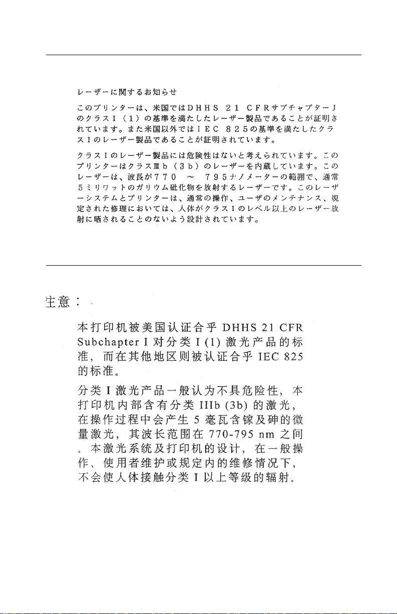
Japanese Laser Notice
Chinese Laser Notice
Notices and Safety Information xv
Page 16
4026-0XX
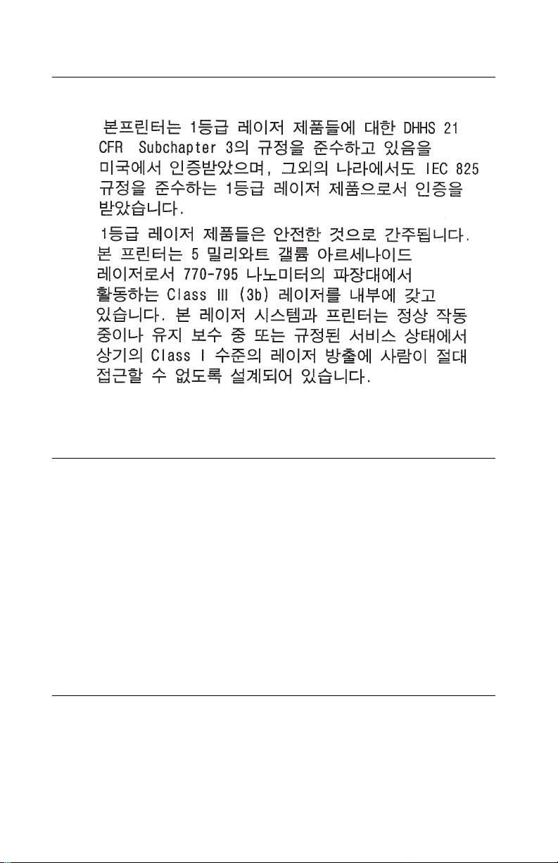
Korean Laser Notice
Safety Information
• The maintenance information for this product has been prepared
for use by a professional service person and is not intended to
be used by others.
• There may be an increased risk of electric shock and personal
injury during disassembly and servicing of this product.
Professional service personnel should understand this and take
necessary precautions.
• The safety features of some parts may not always be obvious.
Therefore, replacement parts must have the identical or
equivalent characteristics as the original parts.
Sicherheitshinweise
• Die Wartungsinformationen für dieses Produkt sind
ausschließlich für die Verwendung durch einen
Wartungsfachmann bestimmt.
xvi Service Manual
Page 17

4026-0XX
• Während des Auseinandernehmens und der Wartung des
Geräts besteht ein zusätzliches Risiko eines elektrischen
Schlags und körperlicher Verletzung. Das zuständige
Fachpersonal sollte entsprechende Vorsichtsmaßnahmen
treffen.
• Ersatzteile müssen gleiche oder gleichwertige Merkmale wie die
Originalteile aufweisen, da nicht immer offensichtlich ist, welche
Teile des Geräts Sicherheitsmerkmale aufweisen.
Consignes de Sécurité
• Les consignes d'entretien et de réparation de ce produit
s'adressent uniquement à un personnel de maintenance
qualifié.
• Le démontage et l'entretien de ce produit pouvant présenter
certains risques électriques, le personnel d'entretien qualifié
devra prendre toutes les précautions nécessaires.
• Les normes de sécurité de certaines pièces n'étant pastoujours
explicites, les pièces de rechange doivent être identiques ou
conformes aux caractéristiques des pièces d'origine.
Norme di sicurezza
• Le informazioni riguardanti la manutenzione di questo prodotto
sono indirizzate soltanto al personale di assistenza autorizzato.
• Durante lo smontaggio e la manutenzione di questo prodotto, il
rischio di subire scosse elettriche e danni alla persona è più
elevato. Il personale di assistenza autorizzato, deve, quindi,
adottare le precauzioni necessarie.
• Poiché non tutti i pezzi di ri cambio garantiscono la stessa
sicurezza, questi devono avere caratteristiche identiche o
equivalenti a quelle dei pezzi originali.
Pautas de Seguridad
• La información sobre el mantenimiento de este producto está
dirigida exclusivamente al personal cualificado de
mantenimiento.
• Existe mayor riesgo de descarga eléctrica y de daños
Notices and Safety Information xvii
Page 18

4026-0XX
personales durante e l desmontaje y la reparación de la
máquina. El personal cualificado debe ser consciente de este
peligro y tomar las precauciones necesarias.
• Los dispositivos de seguridad de algunas piezas no siempre
pueden reconocerse a simple vista. Por lo tanto, los recambios
deben poseer características idénticas o equivalentes a las de
las piezas originales.
Informações de Segurança
• As informações de segurança relativas a este produto destinam-
se a profissionais destes serviços e não devem ser utilizadas
por outras pessoas.
• Risco de choques eléctricos e ferimentos graves durante a
desmontagem e manutenção deste produto. Os profissionais
destes serviços devem estar avisados deste facto e tomar os
cuidados necessários.
• Os dispositivos de segurança de algumas peças poderão não
ser sempre suficientemente evidentes. Assim, as peças
sobressalentes devem possuir características idênticas ou
equivalentes às peças originais.
Informació de Seguretat
• La informació pel manteniment d’aquest producte està orientada
exclusivament a professionals i no està destinada a ningú que
no ho sigui.
• El risc de xoc elèctric i de danys personals pot augmentar durant
el procés de desmuntatge i de servei d’aquest producte. El
personal professional ha d’estar-ne assabentat i prendre les
mesures convenients.
• Les característiques de seguretat d’algunes de les peces poden
no ser òbvies. Pertant, les característiques dels recanvis hauran
de ser idèntiques o equivalents a les de les peces originals.
xviii Service Manual
Page 19
4026-0XX
Chinese Safety Information
Korean Safety Information
Ozone Information
This product does not produce measurable amounts of ozone gas.
Notices and Safety Information xix
Page 20

4026-0XX
Preface
This manual is divided into the following chapters:
• “General Information” contains a general description of the
printer, options, and the maintenanceapproach used to repairit.
General environmental and safety instructions as well as special
tools and test equipment are listed in this chapter.
• “Diagnostic Information” contains error code table, symptom
table, and service checks used toisolate failing field replaceable
units (FRUs).
• “Diagnostic Aids” contains tests and checks used to locate or
repeat symptoms of printer problems.
• “Repair Information” provides instructions for making printer
adjustments and removing and installing FRUs.
• “Connector Locations” uses illustrations to identify the major
components and test points on the printer.
• “Parts Catalog” contains illustrations and part numbers for
individual FRUs.
xx Service Manual
Page 21

4026-0XX
1. General Information
This printer is a letter-quality page printer designed to attach to an
IBM PersonalComputer or other computers compatible with the IBM
Personal Computer (with 386 processor or higher).
The printer is available in models 4026-06A, 06C, 06D, and 06J
without Flash memory and models 4026-06B and 06F with Flash
memory. Model upgrade is not available.
The printer can print in various pitches and has bit image graphics
capability, allowing the user to print advanced graphics. Model
4026-06D has PostScript Level 2 emulation.
The model 4026-070 printer includes a manual input guide,
additional memory and font selections. The 4026-071 is a label
printing model which also includes a manual input guide, additional
memory and font selections.
Options
Memory upgrade options are 1MB, 2MB, and 4MB. The paper tray
option is a 250 sheet secondary paper tray. Contact your point of
purchase for options available in your country.
Maintenance Approach
The diagnostic information in this manual leads you to the correct
field replaceable unit (FRU) or part. Use the error code charts,
symptom index, service checks, and diagnostic aids to determine
the symptom and repair the failure. After you complete the repair,
perform tests as needed to verify the repair.
Tools Required For Service
Magnetic Phillips Screwdriver
General Information 1-1
Page 22

4026-0XX
Acronyms
CSU Customer Setup
DRAM Dynamic Random Access Memory
EP Electrophotographic Process
EPROM Erasable, Programmable Read-Only
Memory
ESD Electrostatic Discharge
FRU Field Replaceable Unit
HVPS High Voltage Power Supply
LASER Light Amplification by Stimulated Emission
of Radiation
LCD Liquid Crystal Display
LED Light-Emitting Diode
LVPS Low Voltage Power Supply
MROM Masked Read Only Memory
NVRAM Nonvolatile Random Access Memory
OEM Original Equipment Manufacturer
PC Photoconductor
POST Power-On Self Test
ROM R ead Only Memory
SIMM Single In-Line Memory Module
SRAM Static Random Access Memory
UPR Used Parts Return
V ac Volts alternating current
V dc Volts direct current
1-2
Page 23

4026-0XX
2. Diagnostic Information
Start
CAUTION:
interlock switch and the printhead shutter actuator at the same
time. To perform some of the service checks and tests, such as
troubleshooting paper feed problems, you need to actuate the top
coverinterlock switch with the covers opened or removed and power
applied to the machine. It is important for personal safety that you
DO NOT, FOR ANY REASON
when power is on.
Remove power from the printer before you connect or disconnect
any cable or electronic board or assembly for personal safety and to
prevent damage to the printer.
Use the service error code, user error message, symptom table,
service checks, and diagnostic aids in this chapter to determine the
corrective action necessary to repair a malfunctioning printer.
The lights on the operator panel can indicate either a user error
message or service error message. When a service error occurs the
printer stops printing and all operator panel LEDs blink in a
continuous pattern, indicating a service error, until the printer is
powered off. If all operator panel LEDs are blinking, go to the
“Service Error Codes” on page 2-2.
When a user error message occurs, one or two operator panel LEDs
are on solid or blinking. Go to the “User Error Message Table” on
page 2-6.
NEVER
manually actuate or disable the top cover
, disable the printhead shutter actuator
If your machine does not have a service error code and does not
completePOST,gotothe“POST Symptom Table” on page 2-12.If
your machine completes POST without an error, and you have a
symptom, go to the “Symptom Table” on page 2-13. Locate your
symptom and take the appropriate action.
If a service error code appears while you are working on the
machine, go to the “Service Error Codes” on page 2-2 andtakethe
indicated action for that error.
Diagnostic Information 2-1
Page 24
4026-0XX
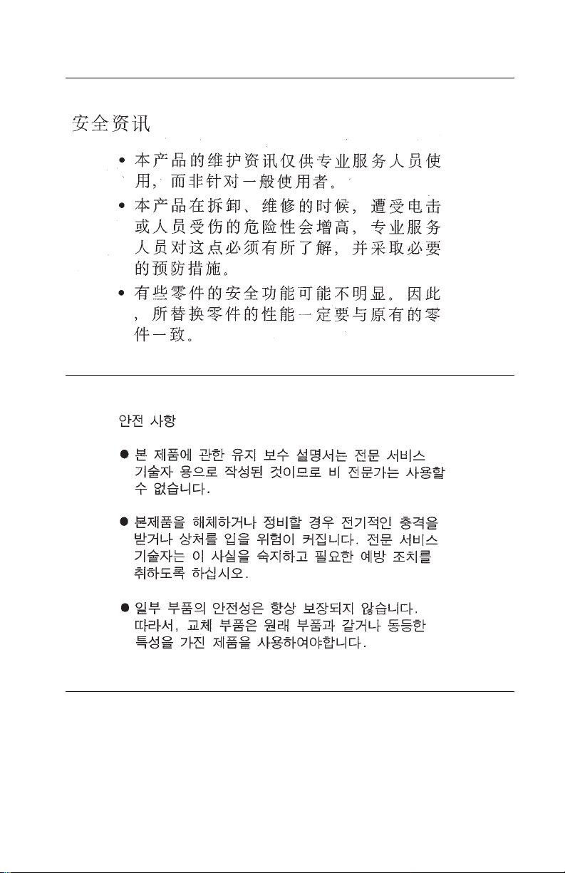
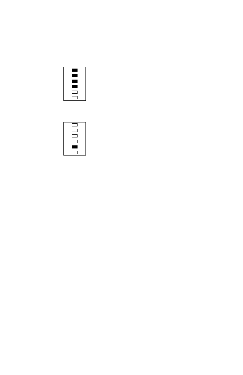
Service Error Codes
When a service error occurs the printer stops printing and all
operator panel LEDs blink in a continuous pattern, indicating a
service error, until the printer is powered off.
Press and release the operator panel button to display the service
error code. Locate the blinking LEDs in the following table and take
the indicated action.
Blinking Operator Panel LED Action
Software Service Error Code Run the Printer Diagnostic Test to
diagnose between the ROM SIMM
and the controller board. If no other
error code displays after the test
completes, replace the controller
board.
Fuser Failure Error Go to the “Cold Fuser Service
Mirror Motor Error The Polygon Mirror Motor is not
Laser Diode Failure Replace the printhead assembly. If
Check” on page 2-18.
rotating during printing. Replace the
engine board. If this does not correct
the problem, replace the printhead
assembly.
this does not correct the problem,
replace the engine board.
2-2
Page 25
4026-0XX
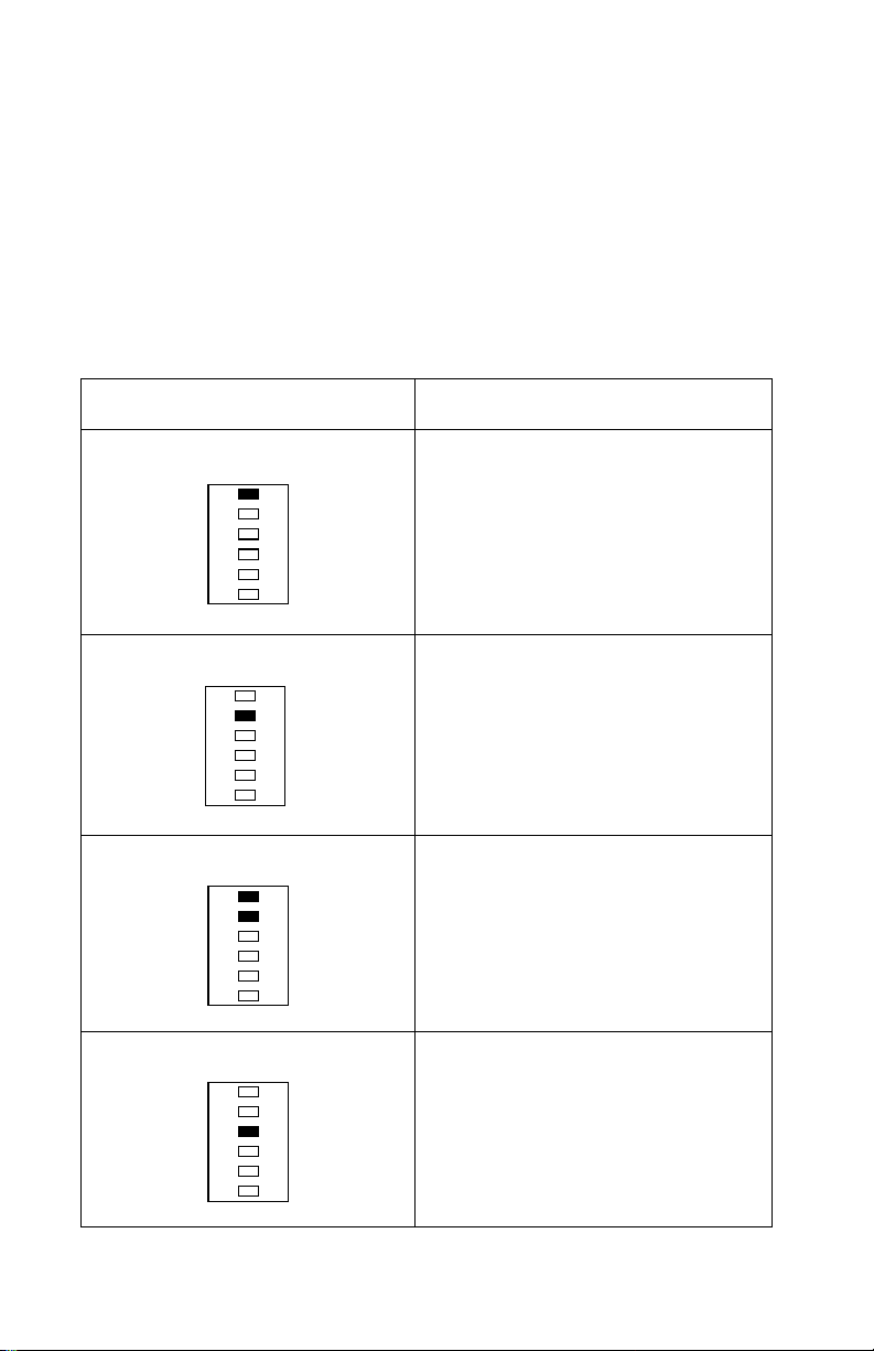
Blinking Operator Panel LED Action
Controller Card Failure Replace Controller board
Optional Memory Error Replace the optional memory SIMM.
If this does not correct the problem,
replace the controller board.
Fan Failure Error Go to the “Fan Service Check” on
page 2-17.
ROM Checksum Error Replace the ROM SIMM. If this does
not correct the problem, replace the
controller board.
Base Memory Error Replace Controller board
Diagnostic Information 2-3
Page 26
4026-0XX
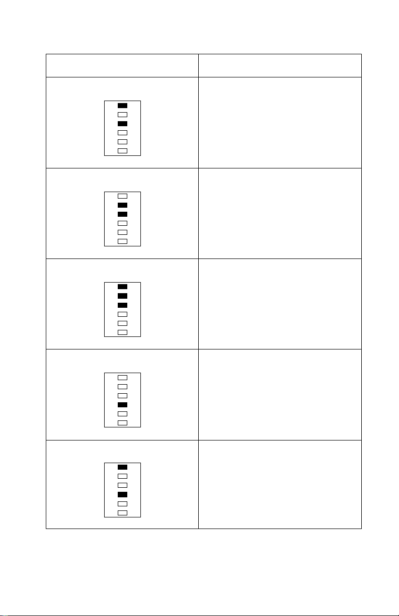
Blinking Operator Panel LED Action
NVRAM Failure Error Replace Controller board
ASIC Register Failure Error Replace Controller board
ASIC SRAM Failure Error Replace Controller board
Flash Memory Failure Error Replace the ROM SIMM w/Flash. If
this does not correct the problem,
replace the controller board.
Font Checksum Failure Error Replace the ROM SIMM. If this does
not correct the problem, replace the
controller board.
2-4
Page 27
4026-0XX
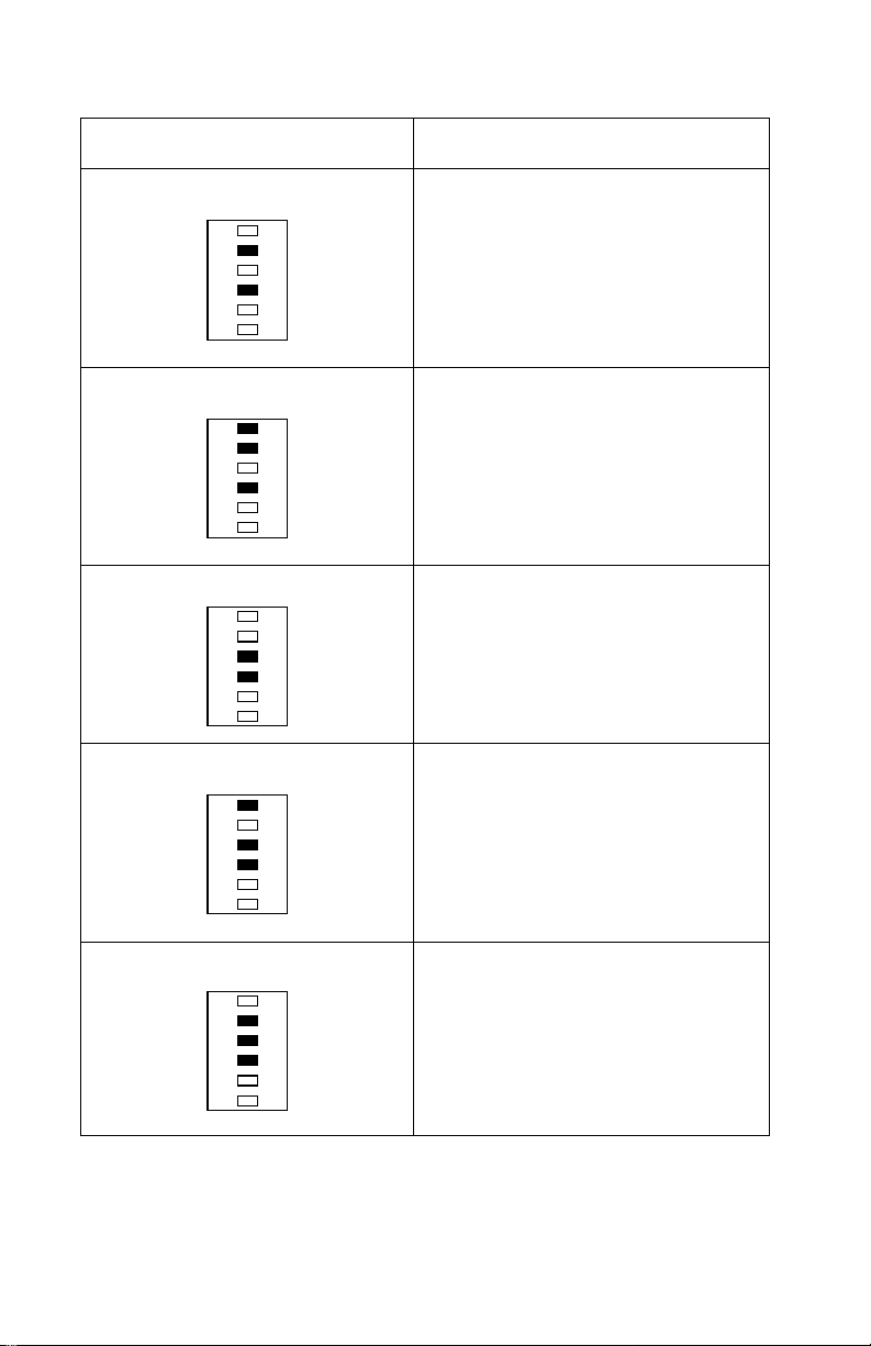
Blinking Operator Panel LED Action
Engine Board Communications
Failure Error
Controller SRAM Failure Error Replace Controller board
Replace the engine board. If this
does not correct the problem,
replace the controller board.
Diagnostic Information 2-5
Page 28

4026-0XX
User Error Message Table
When a user error message occurs the printer stops printing and
one or two operator panel LEDs are on solid or blinking until the
printer is powered off. Locate the printer’s LED Status in the
following table and take the indicated action.
User Error Message LED Status Action
Paper Jam Paper Jam on solid Open cover and clear
anypaperjams.Close
the top cover. If the
error message is still
present, go to the
“Paper Feed Service
Check” on page 2-34.
Load Manual Paper/
Envelope
Load Paper/Load
Envelope
Top Cover Open Error on solid Close the top cover.If
LoadPaperblinksand
Press Button on solid
Load Paper on solid
andPressButtonon
solid
Load media into the
manual slot and push
the operator panel
buttontoresume
printing or do a front
panel reset by pressing and holding the
operator panel button
for more than three
seconds.
Load media in the
appropriate paper tray
and push the operator panel button to
resume printing or do
a front panel reset by
pressing and holding
the operator panel
button for more than
three seconds.
the error LED remains
on solid and POST
does not continue, go
to the “Cover Inter-
lock Service Check”
on page 2-16
2-6
Page 29

4026-0XX
User Error Message LED Status Action
Memory Full/Complex Page/Resolution
Reduction Warning/
Data Transmission
Error
Flash Memory Full Error blinks and Press
Error on solid and
Press Button on solid
Buttononsolid
The printer memory is
full or the page is too
complex to print. The
printer is forced to
reduce the resolution
of a formatted page to
300 dpi before printing, or the printer is
unableto maintain the
required data transfer
rate. Go to the “User
Secondary Error Message Table” on
page 2-8.
This condition only
occurs when the
Flash SIMM is
installed. (4026-06B
or 4026-06F) Go to
the “User Secondary
Error Message Table”
on page 2-8.
Diagnostic Information 2-7
Page 30

4026-0XX
User Secondary Error Message Table
Press and release the operator panel button two times to display the
user secondary error LED status. Each press and release action
must be performed within a half second. Locate the printer’s LED
status in the following table and take the indicated action.
User Error Message LED Status Action
Complex Page Ready, Error, and
Press Button on solid
Memory Full Ready, Data, Error,
andPressButtonon
solid
Switch the printing
mode to a different
printing mode using
the Lexmark driver for
Windows, or push the
operator panel button
to resume printing, or
do a front panel reset
by pressing and holding the operator panel
button for more than
three seconds.
Change the printing
mode to Quick Print
Plus or reduce the
complexity of the job
or the resolution, or
push the operator
panel button to
resume printing, or do
a front panel reset by
pressing and holding
the operator panel
button for more than
three seconds.
2-8
Page 31

4026-0XX
User Error Message LED Status Action
Resolution Reduction Ready, Data blinking
and the Error, Press
Buttononsolid
Data Transmission
Error
Data,Error,andPress
Buttononsolid
Switch from the GL/2
or raster mode to
QuickPrint Plus mode
using the Lexmark
driver for Windows, or
press the operator
panel button to
resume printing, or do
a front panel reset by
pressing and holding
the operator button for
more than three seconds.
Switch to Print Accelerator using the Lexmark driver for
Windows i f 2MB of
memory or more is
installed, or switch to
the GL/2 printing
mode using the Lexmark driver for Windows, or push the
operator panel button
to resume printing, or
do a front panel reset
by pressing and holding the operator panel
button for more than
three seconds.
Flash Memory Full Error blinking and
Press Button on solid
This condition only
occurs when the
Flash memory is full.
Diagnostic Information 2-9
Page 32

4026-0XX
Power-On Self Test (POST)
When you turn the printer on, it performs a Power-On Self Test.
Check for correct POST functioning by observing the following:
1. All LEDs come on solid.
2. The fan turns on for 2 seconds.
3. All the LEDs turn off.
4. The engine board checks the status of the cover interlock
switch.
5. The LEDs begin to turn on then off sequentially.
6. The fan turns off.
7. The engine board checks the status of the paper exit sensor.
8. The engine board checks the status of the thermistor.
9. The fuser lamp turns on.
Note: The printer may be idle for up to 40 seconds asthe fuser
warms to operating temperature. Printer idle time is shorter if
the fuser is already warm.
10. The polygon motor (printhead motor) turns on.
11. The main motor turns on.
12. The paper feed gears turn.
13. The print cartridge drive gear engages.
14. The paper feed take-up shaft and D-roll assembly rotates to
home position. (The paper feed lift plate assembly is in the
down position).
15. All the LEDs turn off.
16. Models 4026-06A, 06C, 06D and 06J,070 and 071 - The Ready
LED turns on solid and the Data LED blinks. Go to Step 17.
Models 4026-06B and 06F- The Ready LED turns on solid and
theDataLEDblinks.
• The controller board checks flash ROM installation.
• The controller board verifies that flash is formatted.
• The controller board attempts to format flash if unformatted.
• The Data LED blinks during format.
• The printer continues POST after format is complete.
• If format fails, a “Flash Memory Failure” error displays.
17. The main drive motor turns off.
2-10
Page 33

4026-0XX
18. The polygon motor (printhead motor) turns off.
19. The Data LED turns off.
20. The Ready LED stays on solid.
If your printer did not successfully complete POST, locate the
symptom in the “POST Symptom Table” on page 2-12 and take the
appropriate action.
If the printer completes all these steps and no error indications are
displayed, the printer has successfully completed the POST. If the
printer has completed POST withoutan error anda symptom exists,
go to the “Symptom Table” on page 2-13.
Diagnostic Information 2-11
Page 34

4026-0XX
POST Symptom Table
Symptom Action
POST completes except one or
more LEDs do not come on.
None of the LEDs come on. Goto the “Operator Panel Service
The printer is dead (No LEDs
come on, no motor turns)
The fan does not come on. Go to the “Fan Service Check” on
The fuser lamp does not come on. Go to the “Cold Fuser Service
Thepolygon motor does not come
on.
The main drive motor does not
come on.
The paper feed gears do not turn. Go to the “Paper Feed Service
The paper feed solenoid picks
and tries to feed paper.
The toner/print cartridge gears do
not turn.
Go to the “Operator Panel Service
Check” on page 2-27.
Check” on page 2-27.
Go to the “Low Voltage Power Sup-
ply Service Check” on page 2-22.
page 2-17
Check” on page 2-18.
Replace the printhead assembly. If
this does not fix the problem, replace
the engine board.
Go to the “Main Drive Motor Service
Check” on page 2-25.
Check” on page 2-34.
Go to the “Paper Feed Service
Check” on page 2-34.
Go to the “Main Drive Motor Service
Check” on page 2-25.
2-12
Page 35

4026-0XX
Symptom Table
Locate your symptom in the following table and take the appropr i ate
action
Symptom Action
Dead printer Go to the “Low Voltage Power Sup-
ply Service Check” on page 2-22.
Fan not working Go to the “Fan Service Check” on
page 2-17.
Fan noisy Go to the “Fan Service Check” on
page 2-17
Fuser parts melted Go to the “Cold Fuser Service
Check” on page 2-18.
Fuser Lamp doesn’t light Go to the “Cold Fuser Service
Check” on page 2-18.
Toner not fused to the paper Go to the “Cold Fuser Service
Check” on page 2-18.
Blank page Go to the “Print Quality Service
Check” on page 2-38.
Black page Go to the “Print Quality Service
High or heavy background Go to the “Print Quality Service
Offset print (image around characters)
Poor image (characters washed
out)
Paper jams Go to the “Paper Feed Service
Main Drive Motor noisy Go to the “Main Drive Motor Service
Main Drive Motor does not move Go to the “Main Drive Motor Service
Main Drive Motor runs backward Replace the Engine board.
Check” on page 2-38.
Check” on page 2-38.
Go to the “Print Quality Service
Check” on page 2-38.
Go to the “Print Quality Service
Check” on page 2-38.
Check” on page 2-34.
Check” on page 2-25.
Check” on page 2-25.
Diagnostic Information 2-13
Page 36

4026-0XX
Symptom Action
Paper is not picked or never
leaves the primary tray
Paper is not picked or never
leaves the optional paper tray
(Tray 2)
Paper feeds continuously Goto the “Paper Feed Service
Paper fails to exit printer or stack
in output bin
Paper skew Go to the “Paper Feed Service
Toner on theback of the page Go to the “Transfer Assembly Ser-
Poor print quality Go to the “Print Quality Service
Incorrect characters print Go to the “Print Quality Service
Printer not communicating with
host
White or black lines or bands Go to the “Print Quality Service
Go to the “Paper Feed Frame
Assembly Service Check” on
page 2-37.
Go to the “Optional Paper Tray Two
Service Check” on page 2-28.
Check” on page 2-34.
Go to the “Paper Feed Service
Check” on page 2-34.
Check” on page 2-34.
vice Check” on page 2-44.
Check” on page 2-38.
Check” on page 2-38.
Go to the “Parallel Port Service
Check” on page 2-34.
Check” on page 2-38.
Paper wrinkled or bent Go to the “Paper Feed Service
Top cover will not close Go to the “Cover Interlock Service
Light print Go to the “Print Quality Service
Check” on page 2-34.
Check” on page 2-16.
Check” on page 2-38
2-14
Page 37

4026-0XX
Service Checks
Charge Brush Service Check
Note: The charge brush charges the photoconductor and is located
inside the photoconductor unit.
FRU Action
1
Photoconductor Unit
Spots and marks can be caused by a defective
charge brush inside the
If there are any spots or marks, especially ones
that appear in the same spot on the printed
page, replace the
photoconductor unit.
photoconductor unit.
Check the
charge brush contact.
2
Main Drive
Motor Gears
3
ChargeBrush
Bias Contact
(right side
frame)
4
Photoconductor Unit
Ground Contact
5
HVPS board Unplug the machine andcheck the HVPS for
Be sure the main drive motor and gears are
operating correctly and turning the charge
brush.
Check the charge brush bias contact located on
the right side frame for damage, corrosion, wear
or pitting. Intermittent failure of the charge brush
contact can cause an all black page, horizontal
black bars or lines. If any of these are found,
replace the charge brush bias contact.
Check the photoconductorunit ground contact
on the right side frame for damage. Intermittent
failureof the photoconductor unit ground contact
can cause print quality problems such as an all
black page, horizontal black bars or lines. If any
of these are found, replace the photoconductor
unit ground contact.
correct mounting, pitted or discolored contacts.
If the HVPS is damaged, replace as necessary.
If no problems are found replace the photoconductor unit assembly.
photoconductor unit for a damaged
Diagnostic Information 2-15
Page 38

4026-0XX
Cover I nterlock Service Check
FRU Action
1
Right Hand
Transfer
Bracket
Check the right hand transfer bracket actuator
arm to be sure it contacts theinterlock switch
actuator mounted in the LVPS.
Replace the bracket if the arm is damaged or
broken.
2
Top Cover
Interlock
Switch
If the interlock switch is being actuated correctly,
check the continuityof the switch between
CN7A-1andCN7A-2onthecableasyouactivate the switch. If incorrect, replace the LVPS.
3
LVPS Be sure the voltage at CN7-1 measures +24 V
dc. If incorrect, turn the printer power off and
disconnect the LVPS cable from theengine
board. Turnthe printer power on. The voltage on
the LVPS cable pin 1 should measure approximately+24Vdc.Ifincorrect,replacetheLVPS.
If correct, go to the “Low Voltage Power Supply
Service Check” on page 2-22.
D-Roll Assembly Service Check
FRU Action
1
D-Roll Check the D-roll for wear, broken, or worn parts.
Replace as necessary.
2
3
4
2-16
D-Roll Clutch
Assembly
Be sure the clutch assembly operates correctly.
Replace as necessary.
Solenoid Be sure the paper feed solenoid operates cor-
rectly. If the solenoid fails to pick, go to the
“Paper Take-Up Solenoid Service Check” on
page 2-32.
Paper Feed
Drive Gears
Be sure the main drive/paper feed gears operate
correctly. Check for broken teeth or damaged
gears. Replace as necessary.
Page 39

4026-0XX
Exit Sensor Service Check
FRU Action
1
2
3
4
Engine Board Disconnect the exit sensor cable from the
Exit Sensor Be sure the exit sensor is snapped in place and
Exit Sensor
Flag
Exit Sensor
Cable
Fan Service Check
FRU Action
1
Engine Board Turn the printer power off. Disconnect CN11
engine board. Check for +4.5 V dc to+5.5 V dc
at CN8-1. If incorrect, replace the engine board.
the cable is firmly connected.
Check the flag for damage and free movement
and replace as necessary. Be sure the exit sensor spring is properly installed and notdisconnected, damaged, or missing.
Reconnect the exit sensor cable and check the
voltage at CN8-3on the engine board as you
press the exit sensor flag. The voltage should
change as the flag is moved in and out of the
sensor.Ifincorrect,replacetheexitsensor.
Check the continuity of the cable. If incorrect,
replace the exit sensor cable.
on the engine board. Turn the printer on and
measure the voltage between CN11-1 and
CN11-2. The voltage should read approximately +24 V dc. If incorrect, replace the
engine board.
If correct, turn the printer off and connect
CN11. Monitor the voltage between ground
and CN11-1 (FAN*)immediately as you power
on the printer.The voltage should go from +24
V dc with the fan motor off to approximately 0
V dc when the motor turns on. If incorrect,
replace the fan motor and cable assembly.
2
Fan Motor/
Cable
Be sure the fan is properly installed if the fan
is noisy. If correct, replace the fan motor
assembly.
Diagnostic Information 2-17
Page 40

4026-0XX
Cold Fuser Service Check
If all the Cold Fuser Service Check items are correct, go to the “Hot
Fuser Service Check” on page 2-20
Note: Toner buildupon the fuser input guide, paper separator, hot
roll and backup roll causes paper jams.
When toner is partially fused to the paper it is usually caused by low
fuser temperature.
Avoid handling the lamp as much as possible as it is easily broken.
Be careful not to touch the glass housing with bare hands as the skin
contains acids that can weaken the glass.
When making checks and handling the fuser lamp make sure you
allow enough time for the fuser l amp and associated parts to cool.
FRU Action
1
2
Line Voltage The voltage to the printer must be within the fol-
lowing limits.
100 V ac (90 V ac - 110 V ac) Japan
120 V ac (108 V ac - 132 V ac) U.S.
220/230 V ac (207 Vac - 253 V ac) W.T.
Fuser Lamp Turn off the printer and wait a few minutes for
thefuserlamptocool.Turnthemachineonand
observe the lamp turning on during POST. You
can see the lamp through the left rear vents of
the top cover. If the lamp lights, be sure the correct voltage lamp is installed. The voltage rating
is stamped on one of the ceramic end pieces.
2-18
Page 41

4026-0XX
FRU Action
3
Thermistor If thefuser lamp comes on and a fuser failure
LED error code displays, be sure the thermistor
is contacting the hot roll and the thermistor
cableisfirmlyseatedinconnectorCN2onthe
engine board.
Checkforexcessivetoner buildup on the surface
of the thermistor. Clean or replace as necessary.
Turn the printer power off and disconnect the
thermistor cable from CN2 on the engine board.
Measure the resistance of the thermistor
between CN2-1 and CN2-2. The resistance
should measure 250K ohms or less. If incorrect,
replace the thermistor and cable assembly. If
correct, replace the engine board.
Note: The thermistor assembly is fragile. Use
care when handling to avoid damage.
4
Fuser Lamp
Cable
If the fuser lamp does not come on and a fuser
failure LED error codedisplays, unplug the
printer power cord and check the continuity
between the fuser cable contacts in the lower
fuser cover. If incorrect, check the continuity of
the fuser lamp, thermal fuse and terminals.
Repair or replace as necessary.If correct, check
the continuity of the fuser lamp cable. If incorrect, replace the cable. If correct, replace the following FRUs one at a time in theorder shown:
Engine Board
LVPS
If the lamp does not come on and the Error LED
is on solid, go to the “Fan Service Check” on
page 2-17
5
Fuser Thermostat (402606C and 06F)
Check the fuser thermostat if the fuser lamp
does not come on or if it comes on and does not
go off. Unplug the printer power cord and check
the thermostat to be sure that it opens and
closes properly.Replace as necessary.
Diagnostic Information 2-19
Page 42

4026-0XX
Hot Fuser Service Check
Note: If you replace the fuser assembly for overheating, also
replace the engine board.
CAUTION: FUSER PARTS MAY BE HOT.
FRU Action
1
2
Fuser Assembly
Engine Board Replace the engine board if the fuser continues
Check for melted or damaged hot roll bearings,
drive gear, paper separators, thermistor, hot roll,
backup roll or frame parts. If the fuser assembly
shows evidence of overheating or thermal damage, repair as necessary.
Note: If the lower fuser frame is damaged,
replace the complete assembly.
to operate erratic or overheats.
Input Sensor Service Check
If the paper never leaves the tray or fails to be picked from the tray,
go to the “Paper Feed Service Check” on page 2-34.
FRU Action
1
2
Paper Check the paper for rough edges, creases,
tears, or folds.
Be sure the paper leaves the paper tray as soon
as it is picked by the D-Roll. If it does not, go to
the “Paper Feed Service Check” on page 2-34.
Envelopes (if
being used)
Be sure no more than 10 envelopes are stacked
in the input paper tray. They may not pick or may
jam at the input sensor or paper separator.
2-20
Note: Coated papers, synthetic papers, multi-sheet
forms, thermal papers, envelopes with windows,
holes, cutouts, perforations, string-ties, metal
fasteners, exposed flap adhesive, excessive curl, bent
corners and some labels cause problems.
Page 43

4026-0XX
FRU Action
3
Input Sensor
Flag
Check the flag for damage, especially at the
front edge, Be sure the flag moves freely.
Replace the flag as necessary.
4
Input Sensor Be sure the input sensor is correctly installed
and the sensor/solenoid cable is properly connected.
Disconnect the input sensor cable from the CN3
connector on the engine board. The voltage at
CN3-1 measures between +4.5 V dc and +5.5 V
dc. If incorrect, replace the engine board.
If correct, reconnect the input sensor cable at
CN3. Monitor the voltage at CN3-3 while moving
the sensor flag in and out. The voltage changes
from +2 V dc to 0 V dc. Ifincorrect, check the
input sensor/solenoid cable continuity. If cable
continuity is incorrect, replace the paper feed
frame assembly. If cable continuity is correct,
replace the following FRUs one at a time in the
order shown:
Input Sensor
Engine Board
Diagnostic Information 2-21
Page 44

4026-0XX
Low Voltage Power Supply Service Check
Note: The controller board, HVPS and printhead assembly receive
power from the LVPS through the engine board.
If the machine is dead, be sure the controller board i s correctly
seated in the engine board connector.
Check and reseat all c ables.
Dead Printer
FRU Action
1
2
3
4
Line Voltage Check the AC line voltage. The voltages should
be within the following limits:
100 V ac (90 V ac - 110 V ac) Japan
120 V ac (108 V ac - 132 V ac) U.S.
220/230 V ac (207 V ac - 253 V ac) W.T.
LVPS The voltage measures approximately +5 V dc
between CN7-4 and ground on the engine
board. If incorrect, disconnect CN7 on the
engine board and measure the voltage between
CN7-4 (+5 V dc) and CN7-3 (+5 V ground). The
reading should measure approximately +5 V dc.
If +5 V dc is not present, unplug the printer line
cord and check fuse F1. If the fuse is open,
replace the fuse. If the fuse is not open, replace
the LVPS.
Engine Board If +5 V dc is present when CN7 is disconnected
then disconnect CN2, CN4, CN5, CN9 and
CN10 from the engine board. Also disconnect
the controller board and remove the ROM SIMM
and any optional memory SIMMs. Reconnect
CN7 and check for +5 V dc. If incorrect, replace
the engine board.
Controller
Board
Reinstall the controller board. Check for +5 V dc
atCN7-4.Ifincorrect,replacethecontroller
board.
2-22
Page 45

4026-0XX
FRU Action
5
ROM SIMM
and Optional
Reinstall the ROM SIMM. Check for +5 V dc at
CN7-4. If incorrect, replace the ROM SIMM.
Memory
SIMM
Reinstall the optional memory SIMM if one was
installed. Check for +5 V dc at CN7-4. If incor-
rect, replace the optional memory SIMM.
6
HVPS Reconnect CN4 and check for +5 V dc at CN7-
4. If incorrect, replace the HVPS.
7
Printhead
Assembly
Reconnect CN5 and CN10. Check for +5 V dc at
CN7-4. If incorrect, replace the printhead
assembly.
8
Thermistor Reconnect CN2 and check for +5 V dc at CN7-
4. If incorrect, replace the thermistor/cable
assembly.
Post Incomplete - ERROR LED remains on solid
Note: Be sure the top cover is closed when doing the following
checks.
FRU Action
1
LVPS Disconnect the LVPS cable from the engine
board.The voltage measures approximately +24
V dc between pin 1 (+24 V dc) and pin 2 (+24 V
dc ground). If incorrect, replace the LVPS.
2
Engine Board Reconnect the LVPS cable and measure the
voltage on CN7-1. The readingshould measure
approximately +24 V dc. If incorrect, disconnect
CN3, CN4, CN6, CN9, CN10 and CN11 from the
engine board. The voltage on CN7-1 measures
+24 V dc. If incorrect, r eplace the engine board.
If correct, reconnect one cable at a time check-
ing the voltage at CN7-1 until the FRU causing
the problem is found. Replace the failing FRU.
If the CN3 or CN9 are causing the problem, it is
necessary to disconnect each solenoid and
check the voltage at CN7-1. Replace the failing
FRU.
Diagnostic Information 2-23
Page 46

4026-0XX
Fuse F1 continues to open after being replaced
FRU Action
1
Fuse F1 If fuse F1 continues to open after being
replaced, disconnect CN7 from the engine
board and turn the printer poweron. If F1 opens,
replace the LVPS.
If F1 does not open with CN7 disconnected,
check the following:
Turn the printer power off and disconnect all the
cables connected tothe engine board and
remove the controller board. Reconnecteach
cable and the controller board one at a time until
the FRU causing F1 toopen is found. Replace
thefailingFRU.
2-24
Page 47

4026-0XX
Main Drive Motor Service Check
FRU Action
1
2
Main Drive
Motor
Left Side
Frame Gears
Disconnect CN6 from the engine board. Check
the motor for shorts between each pin on CN2
and the motor case. If continuity is indicated,
replace the motor.
Check the resistance between the following pins
on the cable connector. If incorrect, replace the
motor. If correct, replace the engineboard.
CN2-1 to CN2-2, 8 - 10 ohms
CN2-1 to CN2-1, 8 - 10 ohms
CN2-1 to CN2-4, 8 - 10 ohms
CN2-2 to CN2-3, 8 - 10 ohms
CN2-2 to CN2-4, 8 - 10 ohms
CN2-3 to CN2-4, 8 - 10 ohms
CN2-1 to CN2-5, 3 - 5 ohms
CN2-2 to CN2-5, 3 - 5 ohms
CN2-3 to CN2-5, 3 - 5 ohms
CN2-4 to CN2-5, 3 - 5 ohms
Remove the toner cartridge and print cartridge.
Manually rotate the paper feed gears on the left
side frame assembly and check for smooth
movement with no binds. If there are binds or
the gears do not turn, repairas necessary.
3
4
Paper Feed
Frame
Assembly
Associated
Gears
Besurethepaperfeedframeassemblyiscor-
rectly installed and the drive gear is engaging
correctly.
Check the fuser gears, print cartridge, transfer
roll gear and photoconductor unit gears to make
sure they turn freely.Repair as necessary.
Diagnostic Information 2-25
Page 48

4026-0XX
FRU Action
5
Motor Noise Checkthe motor for proper mounting, tight
mounting screws, and gearmesh. If incorrect,
repair as necessary.If correct, replace the main
drive motor.
If the motor continues to make noise after the
motor is replaced, replace the engine board.
2-26
Page 49

4026-0XX
Operator Panel Service Check
FRU Action
1
Operator
Panel Assembly
LEDs
Be sure the operator panel cable is properly
seated in J5 on the controller board.
Run POST and check each LED for proper
operation.
If more than one LED does not light or an indi-
vidual LED stays on solid during POST, replace
the following FRUs one at a time in the order
shown:
Controller board
Operator panel
If all LEDs are very dim and operate erratically
during POST or all LEDs come on andstay on
solid during POST replace the following FRUs
one at a time in the order shown:
Operator panel assembly
Controller board
If none of the LEDs are on, be sure +5 V dc is
present at J1-2 on the controller board. If cor-
rect, replace the operator panel assembly. If
incorrect, replace the controller board.
If all the LEDs come on and remain on, replace
the following FRUs one at a time in the order
shown:
Operator Panel Assembly
Controller Board
Button Inoperative
Disconnect the operatorpanel cable at J5 on the
controller board. Check the continuity between
J5-5andJ5-6onthecableasyoupressthebut-
ton. The meter should read from approximately
10K ohms to approximately zero ohms when the
button is pressed.
If the continuity is incorrect, replace the operator
panel assembly. If correct,replace the following
FRUs one at a timein the order shown:
Operator Panel Assembly
Controller Board
Diagnostic Information 2-27
Page 50

4026-0XX
Optional Paper Tray Two Service Check
Check the following before servicing tray two:
• Be sure tray one is working correctly.
• Be sure the second paper tray is correctly installed and the sec-
ond paper tray connector on the base printer properly contacts
the second paper tray connector in the second paper tray.
• Be sure the second paper tray is selected in the user’s applica-
tion and no other application is on the selected port.
• Be sure the base printer and tray two connectors are not dam-
aged.
• Be sure the second paper tray drive gear in the base printer
operates correctly.
• Check the paper feed frame assembly for any obstruction or
damage in the area of the second paper tray feed slot that can
cause the paper to catch or jam.
Note: Only paper can feed from tray two. Envelopes, label sheets,
and transparencies must feed from tray one or manual feed.
Wrinkled or damaged paper
FRU Action
1
2
Paper Check the paper supply for wrinkled, damaged
or out of specification paper. Correct as necessary.
Paper Path Check the paper feed lift plate assembly, paper
empty flag, paper separators, paper feed rollers
or anything in the paper path that might catch
the paper or cause the paper to wrinkle.
Paper fails to leave Paper Tray Two - Solenoid never picks
FRU Action
1
Paper Check the paper supply for any paper that may
cause a problem.
2-28
Page 51

4026-0XX
FRU Action
2
Paper Lift
Plate Assembly
Check the liftplate assembly, release button,
button spring, release arm and all related hard-
ware for proper operation. Be sure thelift plate
D-roll pad mounted on the top of the lift plate is
not worn, contaminated or missing. Repair as
necessary.
3
Paper Empty
Sensor Flag
Check the paper sensor flag for damage and
proper operation. Repair or replace as neces-
sary.
4
Paper Empty
Sensor
Be sure the voltage at CN9-4 on the engine
board is between +4.5 V dc and +5.5 V dc.If
incorrect, replace the engine board. If correct,
check the voltage at CN9-6. The voltage
changes from approximately +2.00 V dc to 0 V
dc as you manually move the sensor flag in and
out of the sensor. If incorrect,be sure tray two
cable measures continuity. If incorrect, replace
the cable. If correct, replace the tray two sensor
board.
5
Second
Paper Tray
Solenoid/
Be sure the solenoid cable is connected to the
paper sensor board cable and the cable is prop-
erly connected to the sensor board.
Engine
Board/Solenoid Cable/
Tray Two
Cable
Disconnect CN9 at the engine board. The volt-
age measures approximately +24 V dc at
CN9-1. If incorrect, replace the engine board. If
correct, reconnect CN9 and measure the volt-
age again at CN9-1. If the voltage continues to
be incorrect, check the resistance of the sole-
noid at the solenoid cable connector which mea-
sures from 60 to 90 ohms. If incorrect, replace
the tray two solenoid. If correct, be sure the
solenoid to sensor board cable measures conti-
nuity. If incorrect, replace the sensor board and
cable assembly. If correct, be sure the tray two
to engine board cable measures continuity. If
incorrect, replace the cable. If correct, replace
the tray two sensor board.
Diagnostic Information 2-29
Page 52

4026-0XX
Paper Tray Two feeds paper. - Paper does not reach the input
sensor in the base printer.
FRU Action
1
2
Second
Paper Tray
Gear Assembly
Second
Paper Tray
Be sure the second paper tray drive assembly
operates properly by manually feeding paper
through the second paper tray. Repair as necessary.
Be sure the D-roll assembly operates properly.
Repair as necessary.
D-Roll
3
Second
Paper Tray
Be sure the D-roll clutch assembly operates
properly. Repair as necessary.
D-Roll Clutch
Assembly
4
Paper Feed
Shaft, Gear
Be sure the paper feed gear, shaft and roller
operate properly. Repair as necessary.
and Roller
5
Paper Feed
Roller,Holder
and Spring
Be sure the paper feed roller, holder and spring
that is mounted on the tray two base frame oper-
ates properly. Repair as necessary.
Assembly
6
Base Printer
Paper Feed
Frame
Be sure there is no obstruction or damage at the
traytwo feed slot in the bottom of the paper feed
frame. Repair as necessary.
Assembly
Note: If the problem appears to be with the base
printer paper feed frame, go to the “Paper Feed
Frame Assembly Service Check” on page 2-37
2-30
Page 53

4026-0XX
Paper Tray Two selected in the application. Paper does not feed
from Tray Two but instead feeds from Tray One. Tray Two reset to
Tray One in printer utility.
FRU Action
1
Engine Board Be sure the voltage at CN9-8 on the engine
board measures approximately 0 V dc. If incorrect, turn the printer power off and measure the
resistance between ground and CN9-8. Be sure
the resistance measures 0 ohms. If incorrect, be
sure the tray two cable measures continuity. If
incorrect, replace the cable. If correct, replace
the following FRUs one at a time in the order
shown:
Engine Board
Tray Two Sensor Board
Diagnostic Information 2-31
Page 54

4026-0XX
Paper Take-Up Solenoid Service Check
FRU Action
1
Solenoid Be sure the solenoid/engine board cable is
firmly seated in connector CN3 on theengine
board.
Be sure the solenoid cable is firmly seated in the
solenoid/engine board cable connector at the
solenoid.
Check the solenoid for proper mechanical oper-
ation and that the solenoid spring is not broken,
loose, or stretched. Replace parts as necces-
sary.
Be sure the solenoid to paper lift plate ground
strap is installed correctly.
Disconnect the solenoid cable from CN3 on the
engine board. Check the resistance of the sole-
noid between CN3-5 and CN3-6 on the cable.
The resistance should measure between 60 to
90 ohms.
Check the continuity of the solenoid/engine
board cable. If the cable continuity is correct,
replace the solenoid. If the cable continuity is
incorrect, replace the paper feed frame assem-
bly.
Disconnect the solenoid from the solenoid/
engine board cable at the solenoid and check
the resistance between each pin on the solenoid
connector and the solenoid frame.If continuity is
indicated, replace the solenoid assembly.
2-32
Page 55

4026-0XX
FRU Action
2
Engine Board Disconnect the solenoid/input sensor cable from
CN3 on the engine board. Check the voltage at
CN3-5. The voltage should measure approximately +24 V dc. If incorrect, replace the engine
board.
If the voltage reads approximately +24 V dc,
check the voltage at CN3-6 while running a test
page. The voltage should measure0 V dc and
read approximately 1 V dc at the time the solenoid should pick. If incorrect, replace the engine
board.
Diagnostic Information 2-33
Page 56

4026-0XX
Parallel Port Service Check
1. Do a print test to be sure the printer prints correctly.
2. Be sure the printer parallel cable is designed for bi-directional
printing.
3. Be sure the user application is set up correctly. Improper set up
can prevent establishing a communication link with the printer.
4. Be sure controller board jumper J3 is located on pins two and
three. J3 in this position causes the parallel port pull-up resistors to be disabled. Some computers have open collector outputs which require enabling the parallel port pull-up resistors.
Do the following to enable the pull-up resistors:
Turn the printer power off.
Place J3 between pins one and two.
Turn the printer power on and run POST.
Run a print test page from the host.
5. If the printer still does not print, return J3 tothe original position.
6. If the internal print test page prints correctly, the user application
and printer driver is set up correctly and the correct printer parallel bi-directional cable is installed.If the printer fails to print on
command from the host, replace the controller board.
Paper Feed Service Check
CAUTION: To check the paper feed it may be necessary to run the
machine with the covers removed and the top cover interlock disabled. If this is necessary, NEVER disable both the top cover interlock and the printhead shutter actuator at the same time.
If it is necessary to run the machine to check for paper feed
problems, open the top cover and disable the top cover interlock
switch. You can feed paper after POST has completed by running
the Normal Mode Print Test. To check some of the paper feed for
proper operation, it may be necessary to remove the toner cartridge
and photoconductor unit assemblies. Do not expose the
photoconductor unit to direct sunlight. Keep it covered. The
photoconductor will be damaged if exposed to light for any length of
time.
2-34
Page 57

4026-0XX
Wrinkled Paper/Envelope/Transparency
FRU Action
1
Paper Checkthe paper supply forwrinkled or damaged
paper, out of specification paper, envelopes or
transparency material. Correct as necessary.
2
Paper Path Check the paper feed lift plate assembly, input
sensor actuator, paper separators, paper feed
rollers or anything in the paper path that might
catch the paper or cause the paper to wrinkle.
Paper Never Leaves The Tray or Fails To Reach The Input Sensor
Note: Remove the Optional Second Paper Tray if installed before
performing the following checks.
FRU Action
1
2
3
Paper Check the paper supply for any paper, envelope,
transparency, label, or index cards that may be
causing a problem.
Paper TakeUp Solenoid
Be sure the paper take-up solenoid is picking. If
incorrect go to the “Paper Take-Up Solenoid
ServiceCheck”onpage2-32.
Paper Frame
Assembly
Checkthe paper feed frame assembly forproper
operation. If incorrect go to the “Paper Feed
Frame Assembly Service Check” on page 2-37.
4
D-Roll
Assembly
Check the D-Roll assembly for proper operation.
If incorrect go to the “D-Roll Assembly Service
Check” on page 2-16
5
6
Paper Lift
Plate Assembly
Print Media
Selection
Lever
Check the paper lift plate assembly for proper
operation. If incorrect, replace the paper lift plate
assembly.
Check the print media selection lever on models
06C and 06F for the correct setting. This is
determined by the media being used ( labels,
card stock, paper, etc. ).
(Models 06C
and 06F)
Diagnostic Information 2-35
Page 58

4026-0XX
Paper Never Reaches The Exit Sensor
FRU Action
1
Input Sensor Check the input sensor for proper operation. If
incorrect, go to the “Input Sensor Service
Check” on page 2-20.
2
D-Roll
Assembly
Check the D-Roll assembly for proper operation.
If incorrect go to the “D-Roll Assembly Service
Check” on page 2-16.
3
Paper Feed
Frame
Assembly
Check the paper feed frame assembly. Ifpaper
is not being fed to the fuser assembly, go to the
“Paper Feed Frame Assembly Service Check”
on page 2-37.
4
Fuser Assembly
Be sure the fuser assembly is free of excessive
toner or other contamination and is operating
correctly. Repair as necessary.
Paper Jam In The Fuser Assembly
FRU Action
1
2
Fuser Assembly
Check the fuser assembly for excessive toner
build-up on the input paper guide, paper separators, hot roll, backup roll and any signs of damage, overheating, or broken and damaged parts.
Repair as necessary.
Exit Sensor Go to the“Exit Sensor Service Check” on
page 2-17.
Any Jam After The Exit Sensor
FRU Action
1
Fuser Assembly
Manually turn the fuser drive gear and be sure
the fuser drive assembly is working correctly.Be
sure the paper feed exit shaft and gearare also
operating properly. Repair as necessary.
2
Exit Sensor Go to the“Exit Sensor Service Check” on
page 2-17.
2-36
Page 59

4026-0XX
FRU Action
3
Paper Feed
Exit Shaft/
Check the paper feed exit shaft, rollers, and
gear for proper operation. Repair as necessary.
Roller
Assembly
4
Paper Feed
Exit Shaft
Be sure the paper feed exit shaft ground termi-
nal is properly installed.
Ground Terminal
Note: A poor ground contact allows static
buildup on the roller and causes paper feed
problems.
5
Top Cover Check the top cover to be sure it does not inter-
fere with the paper as it exits the fuser.
Paper Feed Frame Assembly Service Check
FRU Action
1
2
Paper Check the paper supply for any problems that
might prevent the paper feeding from the paper
feed lift tray .
Frame
Assembly
Check the paper feed roller shaft gear forproper
operation or damage. If incorrect, repair as nec-
essary.Checkthe paper feed roller assembly for
proper operation or damage.If incorrect, replace
the roller assembly.
Checkthe paper separators for sticking, binding,
or damage. Replace as necessary.
Check the frame for signs of damage or warped
surfaces. If incorrect, replace the frame assem-
bly.
Diagnostic Information 2-37
Page 60

4026-0XX
Print Quality Service Check
Before you perform the Print Quality Service Check, do the
following:
• The toner cartridge can cause a variety of print quality prob-
lems. Be sure the toner cartridge is in good condition, works
correctly, and is not low on toner. If in doubt, install a new toner
cartridge before you proceed. The printer does not have a toner
sensor.If the print is light, remove the tonercartridge and gently
shake it to evenly distribute the toner.
• Turn PQET off.
• Set the print darkness setting to normal.
• Place the printer in the 300 dpi mode.
• Be sure the pr inter is clean, especially around the paper path,
print cartridge, and photoconductor unit.
• Some types of paper can cause print quality problems. Print
quality problems can also be caused by extreme environmental
conditions like high temperature and humidity.
• An incorrect printer driver for the installed software can cause
problems.Incorrect characters could print and thecopy may not
fit the page correctly
• Turn off PostScript on model 4026-06D before performing the
Print Quality Service Check.
1
2
3
2-38
FRU Action
Toner Cartridge
Photoconductor Unit
Transfer
Assembly
Be sure the cartridge is installed correctly and
not low on toner. Be sure the tonercartridge
drive operates correctly.
Be sure the photoconductor unit is correctly
installed and the cartridge drive is operating correctly.
If you have vertical marks or horizontal black
bars on the page and these marks or bars are
126 mm (4.9 inches) or 55 mm (2.2 inches)
apart, check the photoconductor unit.
Replace the transfer assembly if you have a horizontal black bar 57 mm from the top of page.
Page 61

4026-0XX
Spot or Marks At Same Spot On Every Print
Note: Do not expose the photoconductor to light any longer than
necessary when you remove the photoconductor unit from the
printer.
FRU Action
1
2
Photoconductor Unit
Assembly
Fuser Paper
Separators
Blank Page
FRU Action
1
2
3
Toner Cartridge
Printhead Be sure the printhead actuator in the top cover
Printhead
Assembly
All Black Page
Remove the photoconductor unit assembly and
check the photoconductor for voids, spots, or
damage.
If black spots are observed approximately 70
mm apart, check the fuser paper separators for
toner buildup. Clean or replace as necessary.
Remove the toner cartridge and gently shake
the assembly to evenly distribute the toner.
actuates the printhead switch in the printhead
assembly.
Blank pages can be caused by a defective print-
head assembly or engine board.If the toner car-
tridge is operating correctly,replace the
printhead assembly. If this does not correct the
problem, replace the engine board.
Note: Incorrect laser exposure or incorrect charging of the photoconductor causes an all black page.
FRU Action
1
Right Side
Frame Terminals
Check for a bent, broken, contaminated, or pit-
ted drum charge bias terminal ordrum ground
terminal located on the right side frame.
Replace as necessary.
Diagnostic Information 2-39
Page 62

4026-0XX
FRU Action
2
3
Cables/Connectors
HVPS Contacts
Be sure the printhead cables to the engine
board are properly seated.
Be sure the HVPS is correctly installed. Be sure
the two high voltage contacts and the ground
contact are not damaged. Repair as necessary.
4
HVPS Cover Check the HVPS cover for pitted or damaged
contacts. Replace as necessary.
5
Printhead
Assembly,
If all the previous checks are correct, replace the
following FRUs one at a time in the order shown:
Engine
Board, HVPS
Printhead Assembly
Engine board
HVPS
White or Black Lines or Bands
Note: Poor image development, incorrect charging of the photocon-
ductor, incorrect laser exposure, poor image transfer, or poor fusing
causes white/black bands or lines.
FRU Action
1
2
2-40
Toner Cartridge
Photoconductor Unit
Remove the toner cartridge and gently shake to
evenly distribute the toner. Check the cartridge
drive gear and contacts for damage. Replace
the toner cartridge as necessary.
Check the photoconductor unit for damage to
the drive gear or contact. Replace as necessary.
Page 63

4026-0XX
FRU Action
3
Transfer
Corona
Cleaning
4
Fuser Assembly
5
Transfer
Assembly
6
Printhead If all the previous checks are correct, replace the
Offset Print
FRU Action
1
Fuser Replace the lower fuser assembly.
Clean the corona wire to remove any toner that
has accumulated. Open the top cover and locate
the cleaning tool. Unsnap the cleaning tool from
its holder. The corona wire is located directly in
front of the transfer unit. Hook the cleaning tool
under the transfer unit with the clear “needle’
facing you. As you slide the cleaning tool back
and forth a few times to remove any toner
buildup, you hear a clicking sound. If you do not
hear this sound, the tool is not seated correctly.
Return the cleaning tool to itsmounting in the
topcoverandclosethecover.
Check the fuser for toner buildup. Be sure the
hot roll, backup roll, and thermistor are not damaged. Repair as necessary.
Go to the “Transfer Assembly Service Check” on
page 2-44.
printhead assembly.
Diagnostic Information 2-41
Page 64

4026-0XX
Excessive Background
Note: Poor development or poorly charged toner particles causes
excessive background. This is more noticeable as the toner cartridge nears end of life.
FRU Action
1
Toner Cartridge, Photoconductor
Unit
White Spots
FRU Action
1
Transfer
Assembly
Be sure the toner cartridge and photoconductor
unit are installed correctly.If installed correctly,
try a new toner cartridge and then a new photo-
conductor unit. If a new toner cartridge or photo-
conductor unit does not correct the problem,
replace the following FRUs one at a time in the
order shown:
HVPS
Engine board
Check the transfer assembly for any signs of
broken parts, pitting, contamination or foreign
objects attached to or in the area of thetransfer
roll.
If no problem is found, replace the following
FRUs one at a timein the order shown:
Transfer Assembly
HVPS
Light Print
1
2-42
FRU Action
Photoconductor Unit
Be sure the photoconductor unit is correctly
installed. Check the cartridge for damage and
pitted or contaminated contacts. If no problem is
found, replace the photoconductor unit.
Page 65

4026-0XX
FRU Action
2
3
Toner Cartridge
Transfer
Assembly
Replace the toner cartridge if the cartridge is
nearing the end of life.
Check the transfer roll for toner buildup and contamination. Clean the transfer roll by performing
POST two or three times.
Light print or black vertical streaks can be
caused by an open transfer leakage current circuit. Check the transfer roll right side contact,
TFR board lead and the TFR Leakage board
(PWB-T) for damage or poorcontact.
If light print is still a problem, replace the following FRUs one at atime in the order shown:
HVPS
Transfer Assembly
TFR Leakage board PWB-T
Engine board
Toner on backside of printed page
Note: Toner on the backof the printed page canbe caused by poor
fusing, improper development, or incorrect charging.
FRU Action
1
Fuser Assembly
Check the hot roll and backup roll for toner
buildup. Clean or replace as necessary.
If the fuser assembly is clean and functioning
correctly, replace the following FRUs one at a
time in the order shown:
HVPS
Engine board
Diagnostic Information 2-43
Page 66

4026-0XX
Registration Service Check
Note: Use the Service Test Page to check the registration.
FRU Action
1
2
Paper Be sure the paper is correctly installed in the
paper tray.
Registration
Adjustment
Perform the registration adjustment when the
engine board is replaced.
Transfer Assembly Service Check
Note: The transfer assembly left and right transfer bracket springs
bias the transfer assembly toward the photoconductor unit. Be sure
the transfer assembly is free to move and biased toward the photoconductor unit.
FRU Action
1
Transfer
Assembly
Be sure the transfer assembly is correctly
installed and the left and right transfer brackets
are properly positioned and fastened. Be sure
the left and right transfer bracket spr ings are
correctly installed and the transfer assembly is
free to move.
Check the transfer roll for toner buildup or dam-
age. Check the transfer roll drivegear for dam-
age or broken teeth. Check the transfer roll for
binds or improper operation and the right side
contact for damage. Replace thetransfer
assembly as necessary.
2-44
Replace the transfer assembly if you have a hor-
izontal black bar 57 mm from the top of page.
Check the Transfer Leakage board, wiring, con-
tacts and transfer roll for signs of damage or
poor contact.
Page 67

4026-0XX
Transfer Corona Service Check
FRU Action
1
Transfer
Corona
Be sure the transfer corona is clean. Clean with
the transfer cleaning tool located onthe upper
fuser cover.
Check the high voltage contacts for pitting, contamination, or damage. Be sure the corona
assembly is correctly installed in the transfer
assembly. Replace as necessary.
Be sure the wires T and TRET are not broken or
damaged, and are properly connected to the
transfer assembly and the HVPS. Replace as
necessary.
ROMSIMMServiceCheck
FRU Action
1
ROM SIMM Be sure the correct ROM SIMM is installed.
Models 4026-06B and 06F require ROM SIMM
with flash.
Be sure the ROM SIMM is correctly installed in
location socket (J8).
Diagnostic Information 2-45
Page 68

4026-0XX
3. Diagnostic Aids
This chapter explains the tests and procedures you can r un to
identify printer failures and verify that repairs have corrected the
problem.
Power-On Self Test (Post)
The printer performs the following Power-On Self Test when
powered on:
1. All LEDs come on solid.
2. The fan turns on for 2 seconds.
3. All the LEDs turn off.
4. The engine board checks the status of the cover interlock
switch.
5. The LEDs begin to turn on then off continuously.
6. The fan turns off.
7. The engine board checks the status of the paper exit sensor.
8. The engine board checks the status of the thermistor.
9. The fuser lamp turns on.
Note: The printer may be idle for up to 40 seconds asthe fuser
warms to operating temperature. Printer idle time is shorter if
the fuser is already warm.
10. The polygon motor (printhead motor) turns on.
11. The main motor turns on.
12. The paper feed gears turn.
13. The print cartridge drive gear engages.
14. The paper feed take-up shaft and D-roll assembly rotates to
home position. (The paper feed lift plate assembly is in the
down position).
15. All the LEDs turn off.
Diagnostic Aids 3-1
Page 69

4026-0XX
16. Models 4026-06A, 06C, 06D and 06J,070 and 071 - The Ready
LED turns on solid and the Data LED blinks. Go to Step 17.
Models 4026-06B and 06F- The Ready LED turns on solid and
theDataLEDblinks.
• The controller board checks flash ROM installation.
• The controller board verifies that flash is formatted.
• The controller board attempts to format flash if unformatted.
• The Data LED blinks during format.
• The printer continues POST after format is complete.
• If format fails, a “Flash Memory Failure” error displays.
17. The main drive motor turns off.
18. The polygon motor (printhead motor) turns off.
19. The Data LED turns off.
20. The Ready LED stays on solid.
If the printer completes all these steps and no error indications are
displayed, the printer has successfully completed the POST.
Diagnostic Aids 3-2
Page 70

4026-0XX
Diagnostic Tests
Printer Diagnostic Test
The following tests run sequentially when performing this test:
Standard Memory Test
Optional Memory Test
Microcode Check
LED Test
Read/Write ASIC Register Test
Read/Write ASIC SRAM Test
Read/Write controller board SRAM Test
Perform the following steps to run the Printer Diagnostic Test:
1. Turn the printer off.
2. Open the top cover.
3. Press and hold the operator panel button as you turn on the
printer. Release the button once the printer’s indicator lights
come on.
4. Wait until the Error LED (top cover open indication) comes on.
5. Close the top cover.
6. The Ready LED comes on solid a nd the Data LED blinks. (This
is the printer Busy Mode indication).
7. If all the diagnostic tests run correctly, the Ready LED goes off
and the Data LED continues to blink. If a test fails, the error light
pattern for the service error code displays on the operator
panel.
3-3
Page 71

4026-0XX
Service Diagnostic Test Page
The service diagnostic test page includes registration marks to aid in
adjusting print registration and also includes the installed printer
base code level. The service test page displays the user default
values for the following:
Top Margin Offset
Left Margin Offset
Printer Page Count
Permanent Page Count
Print Darkness Setting
PQET Setting (on/off)
Toner Saver (on/off)
Print Resolution
Perform the following steps to pr int the Service Diagnostic Test
Page:
1. Turn the printer off.
2. Open the top cover.
3. Press and hold the operator panel button as you turn on the
printer.
4. Wait until the Error LED comes on solid.
5. Close the top cover.
6. The Ready LED is on solid and the Data LED blinks continuously.
7. When the test is complete the Ready LED goes off and the Data
LED continues to blink.
8. Press the operator panel button briefly.
9. The Ready and Data LEDs blink and the Service Diagnostic
Test Page prints. The test page requires several seconds to
start printing.
10. When the test page hasfinished printing the ReadyLED comes
on solid and Data LED goes off.
Note: After the diagnostic test page prints, the printer automatically
exits the diagnostic mode and returns to the normal mode.
Diagnostic Aids 3-4
Page 72

4026-0XX
3-5
Page 73

4026-0XX
User Mode Print Test Page
The User Mode Print Test Page displays the user default values,
installed options, printer features, various typefaces, and the
installed printer base code level.
1. Be sure the Ready LED is on solid (printer is in the readystate).
2. Press and release the operator panel button.
3. The Ready and Data LEDs blink continuously.
4. The test page prints and the operator panel Ready LED comes
on solid and the Data light turns off.
5. The printer returns to the ready state.
Diagnostic Aids 3-6
Page 74

4026-0XX
3-7
Page 75

4026-0XX
Paper Feed Timing
The following describes the timing of paper flow through the printer
to aid in diagnosing paper jam problems. Detection of paper in the
printer paper feed path is accomplished by the low or high status
condition of the paper entry and paper exit sensors. The timing of
the paper as it leaves the input paper tray, passes the input sensor,
exit sensor and into the exit tray, determines normal paper flow or a
paper jam.
Single Sheet Printing: When condition twoin the following list is
detected and there is no paper in the paper path the printer powers
down except for the fuser lamp and fan motor.
Multi Sheet Printing: When condition two in the following list is
detected and paper is in the paper path the printer powers down
except for the fan motor.
• Both the paper entry and paper exit sensors are activated
whenever the printer is turned on or the top cover is closed.
• If the paper does not activate the paper entry sensor in the base
printer within two seconds after the D-roll starts rotating or
within four seconds after the D-roll in theoptional second paper
tray, if installed, starts rotating, a paper feed error occurs.
• If the paper entry sensor does not deactivate within eleven sec-
onds after the paper leading edge has activated the sensor, a
paper jam error occurs.
• If the paper exit sensor is not activated within 3.5 to 4.5 seconds
after the leading edge of the paper has activated the paper
entry sensor, a paper jam error occurs.
• If the paper exit sensor is not deactivated within 3.4 to 4.7 sec-
onds by the trailing edge of the paper, a paper jam error occurs.
Diagnostic Aids 3-8
Page 76

4026-0XX
Fuser Operation
Fuser Mode Printer Action
Warm-Up Mode When the printer power is turned on
the fuser lamp turns on until thehot
roll temperature reaches approximately 172 degrees centigrade.
Standby Mode The hot roll temperature reaches
approximately 156 degrees centigrade. If this temperature is maintained for three minutes, the printer
switches to low temperature standby
mode and the hot roll is maintained
at 112 degrees centigrade.
Print Cycle The hot roll is maintained at 172
degrees centigrade if the engine
board receives a print command
from the controller board.
Note: The hot roll temperature is
slightly higher on models 06C and
06F during the print cycle.
Fuser Control
The thermistor detects the hot roll temperature and sends a
corresponding analog signal to the engine board. The engine board
turns the lamp on or off depending on the analog signal from the
thermistor.
If the thermistor detects a high temperature failure but the fuser lamp
does not turn off, the thermal fuse opens (thermostat on models
4026-06C and 06F) and the engine board turns the fuser lamp off.
3-9
Page 77

4026-0XX
Configuration Mode
The configuration mode gives the ability to set the following printer
functions through the operator panel:
Hex Trace
NPA Mode (Parallel)
Parallel Protocol
Advanced Status
PPDA Activated
Auto CRLF/LFCR
Perform the following steps to enter the configuration mode:
1. Turn the printer power off.
2. Open the top cover.
3. Turn the printer power on.
4. Top Cover Open (Error LED on) is displayed on the operator
panel.
5. Double-click the operator panel button.
6. The printer is in the configuration m ode. The Ready LED is on
solid. The Data, Load Paper, Paper Jam, Error and Press Button are off.
Note: Closing the top cover causes the printer to exit the configuration mode. Repeat the steps to reaccess the configuration mode.
Configuration Mode Operator Panel Overlay
The following overlay indicates the operator panel LED and button
designations when in the configuration mode.
Hex Trace
NPA Mode
Parallel Protocol
Advance Status
CRLF/LFCR
Off/On/Auto
Press three seconds to save
Diagnostic Aids 3-10
Page 78

4026-0XX
Operator Panel Configuration Mode Button Definition
Term Description Result
Brief Button Press Press the operator
panelbuttonnolonger
than three seconds.
Long Button Press Press and hold the
operator panel button
for more than three
seconds.
Double-Click Button
Press
Press and release the
operator panel button
two times. Each press
and release action
must be performed
within a half second.
This action moves
through the configuration mode value list.
This action selects
and saves the value
for the menu item displayed. To indicate
that the setting is
saved, it is displayed
on the operator panel.
This action moves
through the configuration mode value list.
3-11
Page 79

4026-0XX
Hex Trace
UseHexTracetoisolatethecauseofprintproblems.Whenajobis
printed, the printer operator panel displays the Hex Trace indication,
(Ready LED blinking), showing that the printer remains in the Hex
Trace mode. Turn the printer power off or do a front panel reset (long
button press) to exit the Hex Trace mode.
Perform the following steps to enter the Hex Trace mode:
1. Enter the configuration mode.
2. Doabriefbuttonpress.
3. The Ready LED is on and the Press Button (Off/On/Auto) is
on or off indicating the value selected. A brief button press
causes the printer to cycle through the valid settings for Hex
Trace and the Press Button LED turns on or off.
Operator Panel LED Status Action
Off/On/Auto LED and Hex Trace
LED is off
Off/On/Auto LED and Hex Trace
LED is on
A long button press causes the
printer to exit configuration mode
and enter the normal printing mode
or a demo printing mode.
A double-click button press causes
the next menu item, NPA mode, to
display
A long button press causes the
printer to exit the configuration mode
and enter Hex Trace mode.
A double-click button press causes
the next menu item, NPA mode, to
display.
4. Press and hold the button until the Saved setting indication,
(all LEDs on solid) is posted.
5. When the Error LED comes on, close the top cover.
6. The printer completes POST with the Ready LED blinking
indicating the printer is in the Hex Trace mode.
7. Do a double-click to proceed to the next mode. Do an opera-
tor panel reset or turn the printer off to exit the Hex Trace
mode.
Diagnostic Aids 3-12
Page 80

4026-0XX
Restoring Factory Defaults
Restoring factory defaults returns the printer settings to the original
factory settings.
Perform the following steps to invoke factory defaults:
1. Turn the printer power off.
2. Open the top cover.
3. Turn the printer power on. The printer starts POST.
4. The operator panel Error LED comes on solid.
5. Press and hold the operator panel button until all the LEDs
are on solid indicating the printer isrestoring factory defaults.
6. Release the button. The printer indicates the operation is
complete by turning all the LEDs off except the Error LED.
7. The configuration mode canbe selected by doing a brief button press or closing the top cover which causes the printer to
enter either the normal mode or the demo mode.
3-13
Page 81

4026-0XX
4. Repair Information
WARNING: Read the following before handling electronic parts.
Handling ESD-Sensitive Parts
Many electronic products use parts that are known to be sensitive to
electrostatic discharge (ESD). To prevent damage to ESD-sensitive
parts, follow the instructions below in addition to all the usual
precautions, such as turning offpower before removing logic boards:
• Keep the ESD-sensitive part in its original shipping container (a
special “ESD bag”) until you are readyto install thepart into the
machine.
• Make the least-possible movements with your body to prevent
an increase of static electricity from clothing fibers, carpets, and
furniture.
• Put the ESD wrist strap on your wrist. Connect thewrist band to
the system ground point. This discharges any static electricity in
your body to the machine.
• Hold the ESD-sensitive part by its edge connector shroud
(cover); do not touch its pins. If you are removing a pluggable
module, use the correct tool.
• Do not place the ESD-sensitive part on the machine cover or on
a metal table; if you need toput down the ESD-sensitive part for
any reason, first put it into its special bag.
• Machine covers and metal tables a re electrical grounds. They
increase the risk of damage because they make a discharge
path from your body through the ESD-sensitive part. (Large
metal objects can be discharge paths without being grounded.)
• PreventESD-sensitive parts from being accidentally touched by
other personnel. Install machine covers when you are not working on the machine, and do not put unprotected ESD-sensitive
parts on a table.
• If possible, keep all ESD-sensitive parts in a grounded metal
cabinet (case).
• Be extra careful in working with ESD-sensitive parts when cold-
weather heating is used because low humidity increases static
electricity.
Repair Information 4-1
Page 82

4026-0XX
Adjustment Procedures
CAUTION: Be sure to unplug the power cord whenever you are
working on the printer with one of the covers removed.
Print Registration Adjustment
Print the service diagnostic test page after you replace the engine
board. Check the position of the bottom left and right registration
lines. Adjust VR1 on the engine board to position both lines exactly
on the trailing edge of the page. A slight turn on VR1 produces
significant change in the registration line position. Turning the
adjustment clockwise increases the gap between the registration
lines and the trailing edge of the page and counter clockwise
decreases the gap.
4-2
Page 83

4026-0XX
Removal Procedures
CAUTION: Be sure to unplug the power cord whenever you are
working on the printer with one of the covers removed.
Use caution when the photoconductor unit isout of the machine.Do
not expose it to light formore than 15 - 20 minutes.
Screw Identification Table
Repair Information 4-3
Page 84

4026-0XX
Board Cage Removal
1. Remove the controller board.
2. Remove the engine board.
3. Remove the two remaining screws that hold the board cage to
the mainframe.
4. Note the way the cables are routed to the engine board before
removing the board cage.
5. Remove the board cage.
Cover R emovals
Input Paper Tray
1. Press the left and right tray latches to allow the tray to rest at the
lowest position.
2. Press the center of the input paper tray slightly to release the
left and right side frame tabs.
3. Remove the input paper tray.
Left Side Cover
1. Loosen the two screws on the left side frame.
2. Release the bottom cover tabs.
3. Gently pull up and remove the left side cover.
Right Side Cover
1. Remove the two side cover screws that attach the right side
cover to the board cage.
2. Rotate the right side cover down and remove.
Note: Be sure the lower front side cover mounting is properly
snapped into place when you reinstall the right side cover. If installing a new right side cover on models 06C and 06F, transfer the print
registration information label from the old cover to the new cover.
Front Cover
Pullthefrontcoverupandforwardtoremove.
4-4
Page 85

4026-0XX
Top Cover
1. Unplug the power cord from the machine.
2. Remove the toner cartridge and P.C. drum.
3. Remove the left, right, and front covers.
4. Disconnect CN7, CN11, CN2, and CN8 from the engine board.
5. Remove the fuser lamp cable cover.
6. Remove the cable cover from the LVPS.
7. Disconnect the fuser lamp connector from the LVPS.
8. Remove the transfer assembly from the top cover.
9. Carefully disconnect the red leads.
10. Note the mounting and orientation of the left and right transfer
assembly tension springs.
11. Remove the transfer assembly left and right tension springs.
12. Grasp the top cover. Use a screwdriver to pry the top cover left
and right pivot arms from the main frame mounting pins.
13. Remove the top cover.
Controller Board Removal
1. Unplug the power cord from the machine.
2. Remove the right cover.
3. Disconnect the operator panel cable, J5 from the controller
board.
4. Remove the operator panel.
5. Remove the two screws that mount the board cage.
6. Remove the two screws that mount the Centronix parallel
interface connector to the board cage bracket.
7. Remove the three screws that mount the controller board.
8. Remove the controller board.
Repair Information 4-5
Page 86

4026-0XX
D-Roll Removal
1. Remove the paper feed input tray assembly.
2. Remove the paper lift plate assembly.
3. Remove the m anual feed guide plate.
4. Remove the engine board.
5. Remove the controller board.
6. Remove the paper feed frame assembly.
7. Remove the left side plate assembly.
8. Remove the C-clip from both ends of the D-roll shaft.
9. Remove the D-roll clutch cam assembly.
Note: When you remove the clutch cam assembly, the D-roll shaft
pin can fall from the shaft. Be careful not to lose the pin.
10. Slide the D-roll shaft slightly toward the left.
11. Remove the D-roll shaft by lifting and pulling the shaft toward
the center of the printer.
Engine Board Removal
1. Unplug the power cord from the machine.
2. Remove the controller board.
3. Disconnect all the cables from the engine board.
4. Remove the three board mounting screws and remove the
engine board.
Exit Sensor Removal
1. Remove the fuser upper and lower frame assemblies.
2. Disconnect the exit sensor cable.
3. Unsnap the sensor from the frame and remove.
Exit Sensor Flag Removal
1. Remove the fuser upper and lower frame assemblies. Note how
the exit sensor flag torsion spring is mounted.
2. Unsnap the flag from the frame.
Note: Be careful when you handle the flag and spring. They are
easily damaged.
4-6
Page 87

4026-0XX
Exit Paper Feed Roller Assembly Removal
1. Remove the transfer assembly.
2. Remove the fuser upper and lower frame assemblies.
3. Note the orientation of the notches in the left and right bushings.
Reinstall with the notches facing away from the top cover.
4. Be sure the right end of the shaft contacts the ground strap.
Fan Removal
1. Unplug the power cord from the machine.
2. Disconnect the fan cable from the engine board.
3. Remove the top cover.
4. Remove the transfer assembly.
5. Remove the fuser upper and lower frame assemblies.
6. Remove the top cover cable cover.
7. Remove the screw holding the fan assembly to the rear of the
top cover.
8. Unlatch the fan cover assembly from the top cover.
9. Remove the fan assembly.
CAUTION: Be sure the fuser assembly has cooled before
working on any of the following fuser FRUs.
Fuser Lamp Removal
1. Remove the fuser upper frame assembly.
2. Caution: Hold the left side fuser support plate and carefully
remove the support plate screw. There is pressure against the
other end of the lamp therefore care must be used when you
remove the lamp from the fuser. Grip the lamp by the ceramic
end piece and remove it fromthe fuser assembly. Be careful not
to touch the glass.
3. Remove the fuser lamp.
Repair Information 4-7
Page 88

4026-0XX
Fuser Lower Frame Assembly Removal
1. Remove the top cover.
2. Remove the fuser upper frame assembly.
3. Remove the four fuser lower frame assembly mounting screws.
4. Use a screwdriver to unlatch the left end of the fuser cable cover
and remove the cover.
5. Remove the fuser lower frame assembly.
Fuser Upper Frame Assembly Removal
1. Remove the top cover.
2. Remove the left and right transfer assembly mounting brackets
on models 4026-06A, 06B, 06D, and 06J. Remove the left and
right transfer assembly mounting screws on models 4026-06C
and 06F.
3. Remove the five screws that hold the fuser upper frame
assembly and the left hand gear assembly.
4. Disconnect the exit sensor and thermistor cables.
5. Remove the fuser upper frame assembly.
Fuser Paper Separator Removal
1. Remove the top cover.
2. Remove the fuser upper frame assembly.
3. Note the type and location of each separator. The location and
type are determined during manufacture.
4. Use a screwdriver to release the latch that holds the separator
in position.
5. Remove the paper separator.
4-8
Page 89

4026-0XX
HVPS Board Removal
1. Unplug the power cord from the machine.
2. Remove the HVPS cover.
3. Disconnect CN1 from the HVPS board.
4. Disconnect the transfer assembly high voltage connector from
T1 on the HVPS board.
5. Disconnect the red transfer assembly wire at TRET on the
HVPS board.
6. Remove the four HVPS board mounting screws.
7. Remove the HVPS board.
HVPS Cover Removal
1. Unplug the power cord from the machine.
2. Remove the screw holding the HVPS cover to the main frame.
3. Insert a screwdriver in the HVPS cover slot and release the
cover latch.
4. Remove the HVPS cover.
Left Side Plate Removal
1. Unplug the power cord from the machine.
2. Remove the left, right, and front covers.
3. Remove the printhead assembly.
4. Remove the main drive motor.
5. Remove the four screws holding the left side plate to the main
frame.
6. Slide the left side plate toward the front of the machine and
remove.
Note: The main drive/paper feed gears are free to fall from their
mounting studs with the left side plate removed. Be careful not to
lose the gears.
Repair Information 4-9
Page 90

4026-0XX
LVPS Removal
1. Remove the top cover.
2. Remove the four screws that secure the back of the rear frame
to the LVPS.
3. Remove the two screws that hold the top of the rear frame to the
LVPS and remove the rear frame.
4. Remove the two screws mounting the on/off switch to the main
frame.
5. Remove the four screws holding the LVPS to the main frame.
6. Maneuver and lift the LVPS from the main frame.
Main Drive Motor Removal
1. Unplug the power cord from the machine.
2. Remove the right, left, and front covers.
3. Disconnect the main drive motor cable CN6 from the engine
board.
4. Remove the two screws mounting the main drive motor to the
left side plate.
5. Remove the main drive motor.
Main Drive/Paper Feed Gears Removal
1. Unplug the power cord from the machine.
2. Remove the right, left, and front covers.
3. Remove the printhead assembly.
4. Remove the main drive motor.
5. Remove the left side plate.
6. Remove the main drive/paper feed gears.
Manual Paper Feed Guide Plate Removal
1. Remove the paper feed input tray assembly.
2. Remove the paper lift plate assembly.
3. Remove the s crew holding the manual feed guide plate to the
main frame.
4. Remove the manual paper feed guide plate.
4-10
Page 91

4026-0XX
Operator Panel Removal
1. Unplug the power cord from the machine.
2. Remove the toner cartridge and P.C. drum.
3. Disconnect the operator panel cable from the controller board.
4. Loosen the frontoperator panel mounting screwfrom the board
cage.
5. Remove the rear operator panel mounting screw from the board
cage.
6. Remove the operator panel.
Paper Entry Sensor Removal
1. Remove the paper feed input tray assembly.
2. Remove the paper lift plate assembly.
3. Remove the manual feed guide plate.
4. Remove the engine board.
5. Remove the controller board.
6. Remove the paper feed frame assembly.
7. Disconnect the paper entry sensor cable.
8. Use a screwdriver to release the paper entry sensor latches.
9. Remove the paper entry sensor.
Paper Entry Sensor Flag Removal
1. Remove the paper feed input tray assembly.
2. Remove the paper lift plate assembly.
3. Remove the manual feed guide plate.
4. Remove the engine board.
5. Remove the controller board.
6. Remove the paper feed frame assembly.
7. Use a screwdriver to gently apply outward pressure on the flag
pivots to release the flag from the mounting.
8. Remove the paper entry sensor flag.
Repair Information 4-11
Page 92

4026-0XX
Paper Feed Frame Assembly Removal
1. Unplug the power cord from the machine.
2. Remove the paper feed input tray assembly.
3. Remove the paper lift plate assembly.
4. Remove the m anual feed guide plate.
5. Disconnect the paper feed sensor/solenoid cable CN3 from the
engine board.
6. Remove the engine board.
7. Remove the controller board.
8. Remove the paper feed frame assembly.
Paper Feed Solenoid Removal
1. Remove the paper feed input tray assembly.
2. Remove the paper lift plate assembly.
3. Remove the m anual feed guide plate.
4. Remove the engine board.
5. Remove the controller board.
6. Remove the paper feed frame assembly.
7. Remove the paper feed solenoid mounting screw.
8. Disconnect the solenoid cable.
9. Remove the paper feed solenoid.
Paper Feed Input Tray Assembly Removal
1. Place the printer on it’s back.
2. Remove the four screws holding the paper feed input tray
assembly to the frame.
3. Remove the paper feed input tray assembly.
Paper Lift Plate Assembly Removal
1. Place the printer on it’s back.
2. Remove the paper feed input tray assembly.
3. Press the lift plate assembly to the left.
4. Remove the paper lift plate assembly.
4-12
Page 93

4026-0XX
Paper Separator Removal
1. Remove the paper feed input tray assembly.
2. Remove the lift plate assembly.
3. Remove the manual feed guide plate.
4. Remove the engine board.
5. Remove the controller board.
6. Remove the paper feed frame assembly.
7. Use a screwdriver to release either side of the separator
latches.
8. Remove the paper separator.
Printhead Removal
1. Unplug the power cord from the machine.
2. Remove the left, right, and front covers.
3. Disconnect CN5 and CN10 printhead cables from the engine
board.
4. Remove the four screws from the main frame.
5. Remove the 14 mm screw located in the center of the lower
frame.
6. Gently pry the printhead locator tabs from the left and right main
frame mounting slots and remove the printhead.
Print Media Selection Lever Removal (06C/06F/071)
1. Place the printer on it’s back.
2. Remove the selection lever mounting screw.
3. Remove the print media selection lever.
Second Paper Tray Option Connector Removal
1. Unplug the power cord from the machine.
2. Remove the left, right, and front covers.
3. Disconnect the CN9 cable from the engine board.
4. Remove the two screws holding the option connector to the
main frame.
5. Remove the second paper tray option connector.
Repair Information 4-13
Page 94

4026-0XX
Thermal Fuse Removal (06A/06B/06D/06J/070)
1. Remove the top cover.
2. Remove the fuser upper frame assembly.
3. Remove the two screws mounting the thermal fuse.
4. Remove the thermal fuse.
Thermostat Removal (06C/06F/071)
1. Remove the top cover.
2. Remove the fuser upper frame assembly.
3. Remove the two thermostat mounting screws.
4. Remove the fuser thermostat.
Thermistor Removal
1. Remove the fuser lower frame assembly.
2. Remove the screw that holds the thermistor to the left side of
the fuser lower frame assembly.
3. Note the routing of the thermistor cable and remove the
thermistor.
Transfer Unit Removal
Models 4026-06A, 06B, 06D, 06J and 070
1. Remove the top cover.
2. Remove the screw holding the right transfer assembly bracket.
3. Note the mounting and orientation of the left and right transfer
assembly tension springs.
4. Remove the transfer assembly.
5. Remove the transfer assembly tension springs.
4-14
Page 95

4026-0XX
Models 4026-06C, 06F and 071
1. Open the top cover.
2. Remove the transfer cable cover screw and transfer cable cover.
3. Remove the two screws that hold the transfer unit to the rear of
the top cover.
4. Unplug the wire to the transfer roll assembly. Pay attention to
the wire routing.
5. Remove the transfer unit.
Repair Information 4-15
Page 96

4026-0XX
5. Connector Locations
Low Voltage Power Supply
Connector Pin No. Signal
CN1 Engine Board 1+24Vdc
2GND
3GND
4+5Vdc
5FUSERLAMP*
CN2 Fuser Lamp/
Thermal Fuse
1HEATN
2 NO CONNECTION
3HEATL
Connector Locations 5-1
Page 97

4026-0XX
High Voltage Power Supply
Connector Pin No. Signal
CN1 Engine Board 1HVC
2HVT*
3HVSEL2*
4HVSEL1*
5HVB
6BIASMON
7GND
8+24Vdc
T T HV to TRANSFER
CORONA CHARGE
TRET TRET HV to TRANSFER
CORONA HOUSING
Connector Locations 5-2
Page 98

4026-0XX
Engine Board
CN1A Controller Board
Pin No. Signal Pin No. Signal
1 NO CONNECTION 16 CMD*
2 NO CONNECTION 17 CTBSY*
3 NO CONNECTION 18 PRINT*
4 NO CONNECTION 19 SRCLK*
5GND 20 GND
6 RESET* 21 GND
7 GND 22 VIDEO*
8GND 23 +5Vdc
9GND 24 GND
10 HSYND* 25 +5 V dc
11 EPRDY* 26 GND
12 PRRDY* 27 +5 V dc
13 TDD* 28 CPRDY*
14 ETBSY* 29 +5 V dc
15 STS* 30 TEST*
Connector Pin Signal
CN2A Thermistor 1 THERMISTOR
2+5Vdc
CN3A Paper Entry
Sensor and Paper
Take-up Solenoid
1 ANODE (PC1)
2GND
3PC1*
4 NO CONNECTON
5+24Vdc
6FEED1*
5-3
Page 99

4026-0XX
Connector Pin Signal
CN4A HVPS 1HVC
2HVT*
3HVSEL2*
4HVSEL1*
5HVB
6BIASMON
7GND
8+24Vdc
CN5A Laser Diode
Drive Board
CN6A Main Motor 1PHASEA
CN7A LVPS 1+24Vdc
CN8A Paper Exit Sensor
1SSCAN
2CO
3 LD APC2 (LDVR2)
4 LD APC1 (LDVR1)
5GND
6LDATA*
7+5Vdc
2PHASEA*
3PHASEB
4PHASEB*
2GND
3GND
4+5Vdc
5FUSERLAMP*
1 ANODE (PC3)
2GND
3PC3*
Connector Locations 5-4
Page 100

4026-0XX
Connector Pin Signal
CN9A 2nd Paper Tray
(Option)
CN10A Polygon Motor 1 NO CONNECTION
CN11A Fan Motor 1FAN*
1+24Vdc
2FEED2*
3 NO CONNECTION
4+5Vdc
5GND
6 P EMP2
7PSIZED
8 2NDBIN*
9 MM/INCH
10 CHECK0*
11 CHECK1*
12 CHECK2*
2+24Vdc
3GND
4+5Vdc
5 POLYGON CONTROL
2+24Vdc
5-5
 Loading...