

Page 1

• Table of Contents
• Start Diagnostics
• Safety and Notices
• Trademarks
Optra™ N
4040
•Index
• Main Menu
Lexmark and Optra are trademarks of
Lexmark International, Inc., registered
in the United States and/or other
countries.exmark International, Inc.
Page 2

4040
Second Edition (November, 1996)
The following paragraph does not apply to the united kingdom or any
country where such provisions are inconsistent with local law:
INTERNATIONAL, INC. PROVIDES THIS PUBLICATION “AS IS” WITHOUT
WARRANTY OF ANY KIND, EITHER EXPRESS OR IMPLIED, INCLUDING,
BUT NOT LIMITED T O , THE IMPLIED W ARRANTIES OF MERCHANTABILITY
OR FITNESS FOR A PARTICULAR PURPOSE. Some states do not allow
disclaimer of express or implied warranties in certain transactions, therefore,
this statement may not apply to you.
This publication could include technical inaccuracies or typographical errors.
Changes are periodically made to the information herein; these changes will be
incorporated in later editions of the publication. Improvements or changes in the
products or the programs described in this publication may be made at any
time. Publications are not stocked at the address given below; requests for
publications should be made to your point of purchase.
Comments may be addressed to Lexmark International, Inc., Department D22/
035-3, 740 New Circle Road, Lexington, Kentucky 40550, U.S.A. Lexmark may
use or distribute any of the information you supply in any way it believes
appropriate without incurring any obligation to you.
Lexmark and Optra are trademarks of Lexmark International, Inc., registered in
the United States and/or other countries.
LocalT alk is a trademark of Apple, Inc., registered in the United States and other
countries.
Other trademarks are the property of their respective owners.
© Copyright Lexmark International, Inc. 1996. All Rights Reserved
UNITED STATES GOVERNMENT RESTRICTED RIGHTS
This software and documentation are provided with RESTRICTED RIGHTS.
Use, duplication or disclosure by the Government is subject to restrictions as
set forth in subparagraph (c)(1)(ii) of the Rights in T echnical Data and Computer
Software clause at DFARS 252.227-7013 and in applicable FAR provisions:
Lexmark International, Inc., Lexington, KY 40550.
LEXMARK
.
Page 3

4040
g
Contents
Notices and Safety Information . . . . . . . . . . . . . . . . . . . . . . . . . . xii
Laser Notice . . . . . . . . . . . . . . . . . . . . . . . . . . . . . . . . . . . . . . . xii
Safety Information. . . . . . . . . . . . . . . . . . . . . . . . . . . . . . . . . . . xx
Preface . . . . . . . . . . . . . . . . . . . . . . . . . . . . . . . . . . . . . . . . . . . . xxv
General Information . . . . . . . . . . . . . . . . . . . . . . . . . . . . . . . . . . .1-1
Options . . . . . . . . . . . . . . . . . . . . . . . . . . . . . . . . . . . . . . . . . . 1-1
Maintenance Approach. . . . . . . . . . . . . . . . . . . . . . . . . . . . . . 1-1
Tools. . . . . . . . . . . . . . . . . . . . . . . . . . . . . . . . . . . . . . . . . . . . 1-2
Abbreviations . . . . . . . . . . . . . . . . . . . . . . . . . . . . . . . . . . . . . 1-3
nostic Information . . . . . . . . . . . . . . . . . . . . . . . . . . . . . . . .2-1
Dia
Diagnostic Approach. . . . . . . . . . . . . . . . . . . . . . . . . . . . . . . . 2-1
Start . . . . . . . . . . . . . . . . . . . . . . . . . . . . . . . . . . . . . . . . . . . . 2-1
Initial Check . . . . . . . . . . . . . . . . . . . . . . . . . . . . . . . . . . . 2-1
Troubleshooting . . . . . . . . . . . . . . . . . . . . . . . . . . . . . . . . . . . 2-3
Error Code/Message Tables. . . . . . . . . . . . . . . . . . . . . . . . . . 2-4
Service Error Codes. . . . . . . . . . . . . . . . . . . . . . . . . . . . . 2-4
Operator Codes . . . . . . . . . . . . . . . . . . . . . . . . . . . . . . . . 2-7
Diagnostic Information . . . . . . . . . . . . . . . . . . . . . . . . . . . 2-9
Symptom Tables. . . . . . . . . . . . . . . . . . . . . . . . . . . . . . . . . . 2-11
Print Quality Symptom Table . . . . . . . . . . . . . . . . . . . . . 2-11
Paper Feed Symptom Table . . . . . . . . . . . . . . . . . . . . . 2-12
Other Malfunction Symptom Table. . . . . . . . . . . . . . . . . 2-13
Paper Deck Symptom Table . . . . . . . . . . . . . . . . . . . . . 2-15
Base Machine Service Checks. . . . . . . . . . . . . . . . . . . . . . . 2-16
AC Power Input Service Check . . . . . . . . . . . . . . . . . . . 2-16
DC Power Input Service Check . . . . . . . . . . . . . . . . . . . 2-17
Duplex Horizontal Registration Guide Service Check . . 2-18
Fan Motor Service Check (927) . . . . . . . . . . . . . . . . . . . 2-19
Power Supply Fan (FM1) Check . . . . . . . . . . . . . . . .2-20
Fuser/Printhead Fan (FM2) Check . . . . . . . . . . . . . .2-20
Electrical Assembly Fan (FM3) Check . . . . . . . . . . .2-21
Fuser Fan (FM4) Check . . . . . . . . . . . . . . . . . . . . . .2-21
Fuser (Abnormal Temperature) Service Check (923) . . 2-22
Fuser (Temperature Low) Service Check (920/922) . . . 2-23
Fuser (Wrong Type) Service Check (924) . . . . . . . . . . . 2-24
High-Voltage Power Supply Output Service Check . . . . 2-24
Lifting Plate (Multipurpose Tray) Service Check . . . . . . 2-25
Main Motor Service Check. . . . . . . . . . . . . . . . . . . . . . . 2-25
Paper Pick-Up from Envelope Feeder Service Check . . 2-26
Paper Pick-Up from Cassettes Service Check. . . . . . . . 2-26
Contents iii
Page 4

4040
Base Machine Service Checks (Continued)
Paper Pick-Up from Multipurpose Tray Service Check. 2-27
Printhead Service Check. . . . . . . . . . . . . . . . . . . . . . . . 2-28
Printhead/Laser Service Check. . . . . . . . . . . . . . . . . . . 2-28
Printhead/Scanner Motor Service Check . . . . . . . . . . . 2-29
Registration Roller Service Check. . . . . . . . . . . . . . . . . 2-29
Print Quality Service Checks . . . . . . . . . . . . . . . . . . . . . . . . 2-30
Black Page Service Check:. . . . . . . . . . . . . . . . . . . . . . 2-30
Blank Spots Service Check. . . . . . . . . . . . . . . . . . . . . . 2-30
Blank Page Service Check . . . . . . . . . . . . . . . . . . . . . . 2-31
Dark Image Service Check . . . . . . . . . . . . . . . . . . . . . . 2-32
Dirt on Back of Paper Service Check . . . . . . . . . . . . . . 2-32
Dirty Image Service Check . . . . . . . . . . . . . . . . . . . . . . 2-33
Distorted Print Service Check . . . . . . . . . . . . . . . . . . . . 2-33
Light Image Service Check . . . . . . . . . . . . . . . . . . . . . . 2-34
Poor Fusing Service Check. . . . . . . . . . . . . . . . . . . . . . 2-35
Sharp Black Horizontal Lines Service Check . . . . . . . . 2-35
Smudged Horizontal Bands Service Check. . . . . . . . . . 2-36
Vertical Dots in a Line Service Check . . . . . . . . . . . . . . 2-36
Vertical Streaks/Lines Service Check . . . . . . . . . . . . . . 2-37
White Horizontal Lines Service Check . . . . . . . . . . . . . 2-37
White Vertical Lines Service Check. . . . . . . . . . . . . . . . 2-38
Paper Feed Service Checks . . . . . . . . . . . . . . . . . . . . . . . . 2-39
Bent Leading Edge of Paper Service Check . . . . . . . . . 2-40
Duplexing Assembly Paper Jams Service Check . . . . . 2-41
Envelope Feeder Paper Jams Service Check. . . . . . . . 2-42
Fuser and Delivery, Paper Jams Service Check. . . . . . 2-43
Multiple Paper Feed Service Check . . . . . . . . . . . . . . . 2-44
Paper Jam Sensor Service Check. . . . . . . . . . . . . . . . . 2-45
Paper Jam 20, Paper Deck Tray or Feeder . . . . . . . 2-47
Paper Jam 20 . . . . . . . . . . . . . . . . . . . . . . . . . . . . . . 2-47
Paper Jam 21, Input . . . . . . . . . . . . . . . . . . . . . . . . . 2-48
Paper Jam 22, Fuser . . . . . . . . . . . . . . . . . . . . . . . . 2-48
Paper Jam 23, Top Output/Delivery . . . . . . . . . . . . . 2-49
Paper Jam 25, Duplex . . . . . . . . . . . . . . . . . . . . . . . 2-49
Paper Jam 27, Paper Size/Change Paper . . . . . . . . 2-49
Paper Skew Service Check. . . . . . . . . . . . . . . . . . . . . . 2-50
Pick-Up Assembly Paper Jams Service Check. . . . . . . 2-51
Wrinkled Paper Service Check . . . . . . . . . . . . . . . . . . . 2-52
iv Service Manual
Page 5

4040
g
Paper Deck Service Checks. . . . . . . . . . . . . . . . . . . . . . . . . 2-53
Paper Deck Feed Roller Service Check. . . . . . . . . . . . . 2-53
Paper Deck Lifting Plate Service Check. . . . . . . . . . . . . 2-53
Paper Deck Motor Service Check . . . . . . . . . . . . . . . . . 2-55
Paper Deck Paper Pick-Up Service Check . . . . . . . . . . 2-55
Paper Deck Power Input Service Check . . . . . . . . . . . . 2-57
Paper Deck Registration Roller Service Check . . . . . . . 2-58
Paper Deck Paper Feed Service Checks . . . . . . . . . . . . . . . 2-58
Paper Deck Bent Leading Edge Service Check. . . . . . . 2-58
Paper Deck Left Edge Registration Service Check . . . . 2-59
Paper Deck Multiple Paper Feed Service Check. . . . . . 2-59
Paper Deck Paper Jam Service Check . . . . . . . . . . . . . 2-59
Paper Deck Paper Skew Service Check . . . . . . . . . . . . 2-60
Paper Deck Wrinkled Paper Service Check. . . . . . . . . . 2-60
nostic Aids . . . . . . . . . . . . . . . . . . . . . . . . . . . . . . . . . . . . . .3-1
Dia
Interlock Override. . . . . . . . . . . . . . . . . . . . . . . . . . . . . . . 3-1
Basic Engine Test . . . . . . . . . . . . . . . . . . . . . . . . . . . . . . 3-2
Menu Disable . . . . . . . . . . . . . . . . . . . . . . . . . . . . . . . . . . 3-2
Option-2000 Sheet Paper Deck (Tray 3) Self Test. . . . . . 3-2
Diagnostics Mode. . . . . . . . . . . . . . . . . . . . . . . . . . . . . . . 3-4
Diagnostics Mode Menu Structure. . . . . . . . . . . . . . . . . . 3-4
Diagnostics Mode Tests . . . . . . . . . . . . . . . . . . . . . . . . . . . . . 3-6
Button Test. . . . . . . . . . . . . . . . . . . . . . . . . . . . . . . . . . . . 3-6
Defaults . . . . . . . . . . . . . . . . . . . . . . . . . . . . . . . . . . . . . . 3-6
Disk Test/Clean . . . . . . . . . . . . . . . . . . . . . . . . . . . . . . . . 3-6
Error Log . . . . . . . . . . . . . . . . . . . . . . . . . . . . . . . . . . . . . 3-7
Flash Test. . . . . . . . . . . . . . . . . . . . . . . . . . . . . . . . . . . . . 3-8
LCD Test . . . . . . . . . . . . . . . . . . . . . . . . . . . . . . . . . . . . . 3-8
Memory Tests. . . . . . . . . . . . . . . . . . . . . . . . . . . . . . . . . . 3-8
Page Count . . . . . . . . . . . . . . . . . . . . . . . . . . . . . . . . . . . 3-9
Permanent Page Count . . . . . . . . . . . . . . . . . . . . . . . . . . 3-9
Print Test 1. . . . . . . . . . . . . . . . . . . . . . . . . . . . . . . . . . . . 3-9
Print Test 2. . . . . . . . . . . . . . . . . . . . . . . . . . . . . . . . . . . 3-10
Print Test 3. . . . . . . . . . . . . . . . . . . . . . . . . . . . . . . . . . . 3-10
Print Registration . . . . . . . . . . . . . . . . . . . . . . . . . . . . . . 3-11
Left Margin . . . . . . . . . . . . . . . . . . . . . . . . . . . . . . . .3-11
Top Margin . . . . . . . . . . . . . . . . . . . . . . . . . . . . . . . .3-11
Quick Test . . . . . . . . . . . . . . . . . . . . . . . . . . . . . . . . .3-11
Quick Disk Test . . . . . . . . . . . . . . . . . . . . . . . . . . . . . . . 3-12
Wrap Tests. . . . . . . . . . . . . . . . . . . . . . . . . . . . . . . . . . . 3-12
Contents v
Page 6

4040
Repair Information . . . . . . . . . . . . . . . . . . . . . . . . . . . . . . . . . . . . 4-1
Handling ESD-Sensitive Parts . . . . . . . . . . . . . . . . . . . . . . . . 4-2
Adjustments . . . . . . . . . . . . . . . . . . . . . . . . . . . . . . . . . . . . . . 4-3
Envelope Feeder Separation Guide and Lower Separation
Roller Gap Adjustment . . . . . . . . . . . . . . . . . . . . . . . . . . 4-3
Paper Drawer Cassette Side Registration Adjustment . . 4-4
Service Information . . . . . . . . . . . . . . . . . . . . . . . . . . . . . . . . 4-5
Releasing Plastic Latches . . . . . . . . . . . . . . . . . . . . . . . . 4-5
External Parts Removal Procedures . . . . . . . . . . . . . . . . . . . 4-6
Cover Removal Procedures . . . . . . . . . . . . . . . . . . . . . . 4-6
Face-Down Tray Removal . . . . . . . . . . . . . . . . . . . . . 4-7
Front Cover Removal . . . . . . . . . . . . . . . . . . . . . . . . . 4-8
Upper Cover Removal . . . . . . . . . . . . . . . . . . . . . . . . 4-9
Rear Cover Removal . . . . . . . . . . . . . . . . . . . . . . . . 4-11
Delivery Cover Removal . . . . . . . . . . . . . . . . . . . . . 4-12
MultiPurpose Tray Removal . . . . . . . . . . . . . . . . . . . 4-12
Right Cover Removal . . . . . . . . . . . . . . . . . . . . . . . . 4-13
Left Rear Cover Removal . . . . . . . . . . . . . . . . . . . . . 4-14
Fan Removal Procedures . . . . . . . . . . . . . . . . . . . . . . . 4-15
Power Supply Fan (FM1) Removal . . . . . . . . . . . . . 4-16
Fuser/Scanner Fan (FM2) Removal . . . . . . . . . . . . . 4-17
Electrical Fan (FM3) Removal . . . . . . . . . . . . . . . . . 4-19
Fuser Fan (FM4) Removal . . . . . . . . . . . . . . . . . . . . 4-20
Operator Panel Removal. . . . . . . . . . . . . . . . . . . . . . . . 4-21
Drive System Removal Procedures. . . . . . . . . . . . . . . . . . . 4-22
Drive Unit Removal . . . . . . . . . . . . . . . . . . . . . . . . . . . . 4-22
Main Motor Removal . . . . . . . . . . . . . . . . . . . . . . . . . . . 4-24
Paper Transport System Removal Procedures . . . . . . . . . . 4-25
Pick-Up Unit Removal . . . . . . . . . . . . . . . . . . . . . . . . . . 4-25
Pick-Up Motor Removal . . . . . . . . . . . . . . . . . . . . . . 4-28
Feed Clutch Removal . . . . . . . . . . . . . . . . . . . . . . . . 4-28
Cassette Pick-Up Solenoid Removal . . . . . . . . . . . . 4-29
Delivery Unit Removal. . . . . . . . . . . . . . . . . . . . . . . . . . 4-30
Registration Roller Removal . . . . . . . . . . . . . . . . . . . . . 4-31
Registration Clutch Removal . . . . . . . . . . . . . . . . . . 4-32
Registration Lower Roller Removal . . . . . . . . . . . . . 4-32
Manual Feed Pick-Up Removal. . . . . . . . . . . . . . . . . . . 4-34
Manual Feed Pick-Up Clutch Removal . . . . . . . . . . 4-36
Lifting Plate Solenoid Removal . . . . . . . . . . . . . . . . 4-36
Manual Feeding Pick-Up Roller Removal . . . . . . . . . . . 4-38
Separation Pad Removal. . . . . . . . . . . . . . . . . . . . . . . . 4-39
Pick-Up/Feed/Separation Rollers Removal. . . . . . . . . . 4-40
vi Service Manual
Page 7

4040
Exposure System Removal Procedures. . . . . . . . . . . . . . . . 4-41
Printhead Removal. . . . . . . . . . . . . . . . . . . . . . . . . . . . . 4-42
Electrostatic Imaging/Developing/Cleaning System Removal
Procedures . . . . . . . . . . . . . . . . . . . . . . . . . . . . . . . . . . . . . . 4-43
EP Cartridge. . . . . . . . . . . . . . . . . . . . . . . . . . . . . . . . . . 4-43
Drum Protective Shutter . . . . . . . . . . . . . . . . . . . . . .4-44
Photosensitive Drum . . . . . . . . . . . . . . . . . . . . . . . . .4-44
Transfer Charging Roller Removal. . . . . . . . . . . . . . . . . 4-45
Fuser Removal Procedures . . . . . . . . . . . . . . . . . . . . . . . . . 4-46
Fuser Removal. . . . . . . . . . . . . . . . . . . . . . . . . . . . . . . . 4-47
Fuser Roller Heater Removal. . . . . . . . . . . . . . . . . . . . . 4-48
Thermoswitch Removal . . . . . . . . . . . . . . . . . . . . . .4-49
Thermistor Removal . . . . . . . . . . . . . . . . . . . . . . . . .4-50
Fuser Upper Roller Removal . . . . . . . . . . . . . . . . . .4-51
Fuser Lower Roller Removal . . . . . . . . . . . . . . . . . .4-56
Electronic Components Removal Procedures . . . . . . . . . . . 4-58
Controller Card Removal . . . . . . . . . . . . . . . . . . . . . . . . 4-58
System Board Removal . . . . . . . . . . . . . . . . . . . . . . . . . 4-59
Pick-Up Board Removal. . . . . . . . . . . . . . . . . . . . . . . . . 4-60
Multipurpose Tray Board Removal. . . . . . . . . . . . . . . . . 4-60
Switch/Sensor Board Removal. . . . . . . . . . . . . . . . . . . . 4-61
High Voltage Power Supply Board. . . . . . . . . . . . . . . . . 4-63
Cassette-Size Sensing Boards Removal . . . . . . . . . . . . 4-64
Power Supply Removal . . . . . . . . . . . . . . . . . . . . . . . . . 4-65
Envelope Feeder Removal Procedures . . . . . . . . . . . . . . . . 4-67
Envelope Feeder Cover Removals . . . . . . . . . . . . . . . . 4-67
Rear Cover Removal . . . . . . . . . . . . . . . . . . . . . . . .4-67
Front Cover Removal . . . . . . . . . . . . . . . . . . . . . . . .4-67
Lower Cover Removal . . . . . . . . . . . . . . . . . . . . . . .4-68
Upper Cover Removal . . . . . . . . . . . . . . . . . . . . . . .4-69
Envelope Side Guide Removal . . . . . . . . . . . . . . . . . . . 4-70
Envelope Feeder Pick-Up Motor Removal. . . . . . . . . . . 4-71
Envelope Feeder Driver Board Removal . . . . . . . . . . . . 4-73
Drive Unit Removal . . . . . . . . . . . . . . . . . . . . . . . . . . . . 4-74
Envelope Feeder Pick-Up Roller Removal. . . . . . . . . . . 4-75
Separation Rollers and Torque Limiter Removal . . . . . . 4-75
Contents vii
Page 8

4040
Duplex Assembly Removal Procedures. . . . . . . . . . . . . . . . 4-77
Upper Guide Removal. . . . . . . . . . . . . . . . . . . . . . . . . . 4-77
Lower Guide Removal. . . . . . . . . . . . . . . . . . . . . . . . . . 4-78
Switchback Roller Release Solenoid Removal . . . . . . . 4-80
Duplex Deflector Drive Solenoid Removal . . . . . . . . . . 4-81
Switchback Motor Removal. . . . . . . . . . . . . . . . . . . . . . 4-84
Side Registration Motor Removal . . . . . . . . . . . . . . . . . 4-85
Duplex Feed Clutch Removal . . . . . . . . . . . . . . . . . . . . 4-86
Duplex Driver Board Removal. . . . . . . . . . . . . . . . . . . . 4-87
Paper Deck Removal Procedures . . . . . . . . . . . . . . . . . . . . 4-89
External Covers. . . . . . . . . . . . . . . . . . . . . . . . . . . . . . . 4-89
Front Cover Removal . . . . . . . . . . . . . . . . . . . . . . . . 4-89
Left Cover Removal . . . . . . . . . . . . . . . . . . . . . . . . . 4-89
Right Cover Removal . . . . . . . . . . . . . . . . . . . . . . . . 4-90
Feed Cover Removal . . . . . . . . . . . . . . . . . . . . . . . . 4-91
Rear Cover Removal . . . . . . . . . . . . . . . . . . . . . . . . 4-91
Paper Deck Drive System Removal Procedures . . . . . . . . . 4-92
Drive Assembly Removal . . . . . . . . . . . . . . . . . . . . . . . 4-92
Lifter Clutch Removal . . . . . . . . . . . . . . . . . . . . . . . . 4-93
Deck Motor Removal . . . . . . . . . . . . . . . . . . . . . . . . 4-93
Limit Switch Removal . . . . . . . . . . . . . . . . . . . . . . . . . . 4-94
Paper Transport System Removal Procedures . . . . . . . . . . 4-95
Pick-Up Assembly Removal . . . . . . . . . . . . . . . . . . . . . 4-95
Pick-Up Solenoid Removal . . . . . . . . . . . . . . . . . . . 4-97
Pick-Up Motor Removal . . . . . . . . . . . . . . . . . . . . . . 4-98
Feed Assembly Removal. . . . . . . . . . . . . . . . . . . . . . . . 4-99
Feed Clutch Removal . . . . . . . . . . . . . . . . . . . . . . . 4-100
Registration Clutch Removal . . . . . . . . . . . . . . . . . 4-101
Feed Roller Removal . . . . . . . . . . . . . . . . . . . . . . . 4-102
Registration Roller Removal . . . . . . . . . . . . . . . . . 4-103
Tray Removal . . . . . . . . . . . . . . . . . . . . . . . . . . . . . . . 4-104
Lifter Removal . . . . . . . . . . . . . . . . . . . . . . . . . . . . . . . 4-105
Electronic Component Removal Procedures. . . . . . . . . . . 4-113
Paper Deck Driver Board Removal . . . . . . . . . . . . . . . 4-113
Power Supply Removal. . . . . . . . . . . . . . . . . . . . . . . . 4-113
Paper-size Sensing Switch Board Removal . . . . . . . . 4-114
Paper-level Sensing Switch Board Removal. . . . . . . . 4-115
Locations . . . . . . . . . . . . . . . . . . . . . . . . . . . . . . . . . . . . . . . . . . . 5-1
Parts of the Printer. . . . . . . . . . . . . . . . . . . . . . . . . . . . . . 5-1
Duplexer . . . . . . . . . . . . . . . . . . . . . . . . . . . . . . . . . . . . . 5-3
Envelope Feeder. . . . . . . . . . . . . . . . . . . . . . . . . . . . . . . 5-3
Cross Section View of Printer and Duplexer . . . . . . . . . . 5-4
viii Service Manual
Page 9

4040
Locations (Continued)
Cross Section View of Envelope Feeder . . . . . . . . . . . . . 5-5
Base Machine Sensor and Switch Operation. . . . . . . . . . 5-6
Base Machine Motor and Clutch Operation . . . . . . . . . . . 5-8
Paper Feed. . . . . . . . . . . . . . . . . . . . . . . . . . . . . . . . . . . . 5-9
Duplex Operation . . . . . . . . . . . . . . . . . . . . . . . . . . . . . . 5-10
Paper Deck Sensor and Switch Operation. . . . . . . . . . . 5-12
Switches. . . . . . . . . . . . . . . . . . . . . . . . . . . . . . . . . . . . . 5-14
Sensors . . . . . . . . . . . . . . . . . . . . . . . . . . . . . . . . . . . . . 5-15
Clutches and Solenoids . . . . . . . . . . . . . . . . . . . . . . . . . 5-17
Motor, Fans, and Heaters. . . . . . . . . . . . . . . . . . . . . . . . 5-19
Printed Circuit Boards . . . . . . . . . . . . . . . . . . . . . . . . . . 5-21
Connector Locations . . . . . . . . . . . . . . . . . . . . . . . . . . . 5-23
System Board. . . . . . . . . . . . . . . . . . . . . . . . . . . . . . . . . 5-27
System Board Connector Signals . . . . . . . . . . . . . . . . . 5-28
System Board Connector J201 . . . . . . . . . . . . . . . . .5-28
System Board Connector J201 . . . . . . . . . . . . . . . . .5-30
System Board Connector J202 . . . . . . . . . . . . . . . . .5-30
System Board Connector J203 . . . . . . . . . . . . . . . . .5-30
System Board Connector J204 . . . . . . . . . . . . . . . . .5-30
System Board Connector J205 . . . . . . . . . . . . . . . . .5-32
System Board Connector J206 . . . . . . . . . . . . . . . . .5-32
System Board Connector J207 . . . . . . . . . . . . . . . . .5-32
System Board Connector J208 . . . . . . . . . . . . . . . . .5-32
System Board Connector J209 . . . . . . . . . . . . . . . . .5-33
System Board Connector J210 . . . . . . . . . . . . . . . . .5-33
System Board Connector J212 . . . . . . . . . . . . . . . . .5-33
System Board Connector J213 . . . . . . . . . . . . . . . . .5-33
System Board Connector J214 . . . . . . . . . . . . . . . . .5-35
System Board Connector J215 . . . . . . . . . . . . . . . . .5-35
System Board Connector J216 . . . . . . . . . . . . . . . . .5-35
System Board Connector J217 . . . . . . . . . . . . . . . . .5-36
System Board Connector J218 . . . . . . . . . . . . . . . . .5-36
System Board Connector J219 . . . . . . . . . . . . . . . . .5-36
System Board Connector J220 . . . . . . . . . . . . . . . . .5-38
System Board Connector J221 . . . . . . . . . . . . . . . . .5-38
System Board Connector J222 . . . . . . . . . . . . . . . . .5-38
System Board Connector J223 . . . . . . . . . . . . . . . . .5-40
System Board Connector J225 . . . . . . . . . . . . . . . . .5-40
Switch/Sensor Board . . . . . . . . . . . . . . . . . . . . . . . . . . . 5-40
Cassette Size Sensing Switch Board. . . . . . . . . . . . . . . 5-40
High Voltage Power Supply Board. . . . . . . . . . . . . . . . . 5-41
Contents ix
Page 10

4040
Locations (Continued)
Envelope Feeder Driver Board . . . . . . . . . . . . . . . . . . . 5-41
Paper Deck Switches, Sensors, Clutches, Solenoid, Motors .
5-42
Paper Deck Printed Circuit Boards . . . . . . . . . . . . . . . . 5-43
Paper Deck Connectors . . . . . . . . . . . . . . . . . . . . . . . . 5-44
Paper Deck Driver Board. . . . . . . . . . . . . . . . . . . . . . . . 5-45
Paper Deck Driver Board Connectors. . . . . . . . . . . . . . 5-45
Paper Deck Driver Board Connector J201 . . . . . . . . 5-45
Paper Deck Driver Board Connector J202 . . . . . . . . 5-47
Paper Deck Driver Board Connector J203 . . . . . . . . 5-47
Paper Deck Driver Board Connector J204 . . . . . . . . 5-47
Paper Deck Driver Board Connector J205 . . . . . . . . 5-49
Paper Deck Driver Board Connector J206 . . . . . . . . 5-49
Paper Deck Driver Board Connector J207 . . . . . . . . 5-49
Paper Deck Driver Board Connector J208 . . . . . . . . 5-49
Paper Deck Driver Board Connector J209 . . . . . . . . 5-51
Paper Deck Driver Board Connector J210 . . . . . . . . 5-51
Paper-level Sensing Switch Board . . . . . . . . . . . . . . . . 5-51
Paper-size Sensing Switch Board. . . . . . . . . . . . . . . . . 5-51
Option Controller Interface Connector Locations . . . . . 5-52
Option Controller Interface Connector. . . . . . . . . . . . . . 5-53
Optional I/O Device Interface . . . . . . . . . . . . . . . . . . . . 5-55
Preventive Maintenance . . . . . . . . . . . . . . . . . . . . . . . . . . . . . . . 6-1
Safety Inspection Guide . . . . . . . . . . . . . . . . . . . . . . . . . 6-1
Expected Life of Consumable Parts . . . . . . . . . . . . . . . . 6-1
Maintenance, Customer Checks . . . . . . . . . . . . . . . . . . . 6-2
Service Checkpoints - Printer . . . . . . . . . . . . . . . . . . . . . 6-2
Cartridge - Photosensitive Drum . . . . . . . . . . . . . . . . 6-2
Manual Feeding Pick-Up Roller, Cassette Pick-Up Roller,
Separation Roller, and Feed Roller . . . . . . . . . . . . . . 6-2
Separation Pad . . . . . . . . . . . . . . . . . . . . . . . . . . . . . 6-2
Registration Roller Unit . . . . . . . . . . . . . . . . . . . . . . . 6-2
Transfer Guide . . . . . . . . . . . . . . . . . . . . . . . . . . . . . . 6-3
Transfer Charging Roller . . . . . . . . . . . . . . . . . . . . . . 6-3
Static Charge Eliminator . . . . . . . . . . . . . . . . . . . . . . 6-3
Feed Guide . . . . . . . . . . . . . . . . . . . . . . . . . . . . . . . . 6-3
Fuser . . . . . . . . . . . . . . . . . . . . . . . . . . . . . . . . . . . . . 6-3
Service Checkpoints - Paper Deck . . . . . . . . . . . . . . . . . 6-3
Pick-Up Roller, Separation Roller, Feed Roller . . . . . 6-3
Lubricants and Cleaners . . . . . . . . . . . . . . . . . . . . . . . . . 6-4
x Service Manual
Page 11

4040
g
g
Parts Catalo
. . . . . . . . . . . . . . . . . . . . . . . . . . . . . . . . . . . . . . . .7-1
How To Use This Parts Catalog . . . . . . . . . . . . . . . . . . . . . . . 7-1
Covers and Panels. . . . . . . . . . . . . . . . . . . . . . . . . . . . . . .7-2
Internal Paper Mechanism . . . . . . . . . . . . . . . . . . . . . . . . .7-6
Internal Paper Drawer/Print Cartridge Mtg. . . . . . . . . . . . .7-8
Printhead/System Board . . . . . . . . . . . . . . . . . . . . . . . . .7-12
Power Supply/Fuser Cables. . . . . . . . . . . . . . . . . . . . . . .7-14
Face-Up Solenoid. . . . . . . . . . . . . . . . . . . . . . . . . . . . . . .7-18
High Voltage Power Supply . . . . . . . . . . . . . . . . . . . . . . .7-20
Printer Driver . . . . . . . . . . . . . . . . . . . . . . . . . . . . . . . . . .7-22
Lower Drawer. . . . . . . . . . . . . . . . . . . . . . . . . . . . . . . . . .7-24
Upper Drawer. . . . . . . . . . . . . . . . . . . . . . . . . . . . . . . . . .7-28
Paper Pick-up. . . . . . . . . . . . . . . . . . . . . . . . . . . . . . . . . .7-32
Registration Roller . . . . . . . . . . . . . . . . . . . . . . . . . . . . . .7-42
Feeder . . . . . . . . . . . . . . . . . . . . . . . . . . . . . . . . . . . . . . .7-44
Multipurpose Tray Pick-Up. . . . . . . . . . . . . . . . . . . . . . . .7-46
Multipurpose Tray. . . . . . . . . . . . . . . . . . . . . . . . . . . . . . .7-50
Paper Delivery . . . . . . . . . . . . . . . . . . . . . . . . . . . . . . . . .7-52
Paper Delivery Frame . . . . . . . . . . . . . . . . . . . . . . . . . . .7-54
Fuser . . . . . . . . . . . . . . . . . . . . . . . . . . . . . . . . . . . . . . . .7-56
Controller Card. . . . . . . . . . . . . . . . . . . . . . . . . . . . . . . . .7-60
Envelope Feeder Covers . . . . . . . . . . . . . . . . . . . . . . . . .7-62
Envelope Feeder Drive 1 . . . . . . . . . . . . . . . . . . . . . . . . .7-64
Duplex Option. . . . . . . . . . . . . . . . . . . . . . . . . . . . . . . . . .7-68
Paper Deck, Covers and Frame. . . . . . . . . . . . . . . . . . . .7-76
Paper Deck, Main Body . . . . . . . . . . . . . . . . . . . . . . . . . .7-78
Paper Deck, Paper Drawer . . . . . . . . . . . . . . . . . . . . . . .7-80
Paper Deck Drive. . . . . . . . . . . . . . . . . . . . . . . . . . . . . . .7-86
Paper Deck, Paper Pick-Up . . . . . . . . . . . . . . . . . . . . . . .7-88
Paper Deck, Paper Feed . . . . . . . . . . . . . . . . . . . . . . . . .7-92
Option Controller Card . . . . . . . . . . . . . . . . . . . . . . . . . . .7-96
Options (No Illustration). . . . . . . . . . . . . . . . . . . . . . . . . .7-98
Wirin
Diagram . . . . . . . . . . . . . . . . . . . . . . . . . . . . . . . . . . . . . . .8-1
Index. . . . . . . . . . . . . . . . . . . . . . . . . . . . . . . . . . . . . . . . . . . . . . . X-1
Contents xi
Page 12

4040
Notices and Safety Information
References in this publication to products, programs, or services do
not imply that the manufacturer intends to make these av ailab le in all
countries in which it operates. Any reference to a product, program,
or service is not intended to state or imply that only that product, program, or service may be used. Any functionally equivalent product,
program, or service that does not infringe any existing intellectual
property rights may be used instead. Evaluation and verification of
operation in conjunction with other products, programs, or services,
except those expressly designated by the manufacturer, are the
user’s responsibility.
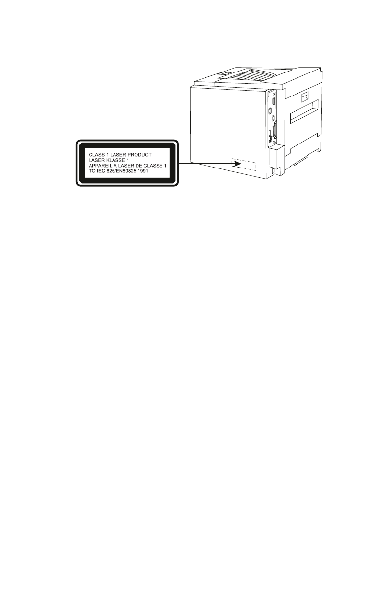
Laser Notice
The printer is certified in the U.S. to conform to the requirements of
DHHS 21 CFR Subchapter J for Class I (1) laser products, and elsewhere is certified as a Class I laser product conforming to the
requirements of IEC 825.
Class I laser products are not considered to be hazardous. The
printer contains internally a Class IIIb (3b) laser that is nominally a 5
milliwatt gallium arsenide laser operating in the wav elength region of
770-795 nanometers. The laser system and printer are designed so
there is never any human access to laser radiation above a Class I
level during normal operation, user maintenance, or prescribed
service condition.
xii Service Manual
Page 13
4040
The Class 1 laser label is attached to the back of the printer.
Laser
Der Drucker erfüllt gemäß amtlicher Bestätigung der USA die
Anforderungen der Bestimmung DHHS (Department of Health and
Human Services) 21 CFR Teil J für Laserprodukte der Klasse I (1).
In anderen Ländern gilt der Drucker als Laserprodukt der Klasse I,
der die Anforderungen der IEC (International Electrotechnical
Commission) 825 gemäß amtlicher Bestätigung erfüllt.
Laserprodukte der Klasse I gelten als unschädlich. Im Inneren des
Druckers befindet sich ein Laser der Klasse IIIb (3b), bei dem es
sich um einen Galliumarsenlaser mit 5 Milliwatt handelt, der Wellen
der Länge 770-795 Nanometer ausstrahlt. Das Lasersystem und der
Drucker sind so konzipiert, daß im Normalbetrieb, bei der Wartung
durch den Benutzer oder bei ordnungsgemäßer Wartung durch den
Kundendienst Laserbestrahlung, die die Klasse I übersteigen würde,
Menschen keinesfalls erreicht.
Avis relatif à l’utilisation de laser
Pour les Etats-Unis : cette imprimante est certifiée conforme aux
provisions DHHS 21 CFR alinéa J concernant les produits laser de
Classe I (1). Pour les autres pays : cette imprimante répond aux
normes IEC 825 relatives aux produits laser de Classe I.
Les produits laser de Classe I sont considérés comme des produits
non dangereux. Cette imprimante est équipée d’un laser de Classe
IIIb (3b) (arséniure de gallium d’une puissance nominale de 5
Notices and Safety Information xiii
Page 14

4040
milliwatts) émettant sur des longueurs d’onde comprises entre 770
et 795 nanomètres. L’imprimante et son système laser sont conçus
pour impossible, dans des conditions normales d’utilisation,
d’entretien par l’utilisateur ou de révision, l’exposition à des
rayonnements laser supérieurs à des rayonnements de Classe I .
Avvertenze sui prodotti laser
Questa stampante è certificata negli Stati Uniti per essere conforme
ai requisiti del DHHS 21 CFR Sottocapitolo J per i prodotti laser di
classe 1 ed è certificata negli altri Paesi come prodotto laser di
classe 1 conforme ai requisiti della norma CEI 825.
I prodotti laser di classe non sono considerati pericolosi. La
stampante contiene al suo interno un laser di classe IIIb (3b)
all’arseniuro di gallio della potenza di 5mW che opera sulla
lunghezza d’onda compresa tra 770 e 795 nanometri. Il sistema
laser e la stampante sono stati progettati in modo tale che le
persone a contatto con la stampante, durante il normale
funzionamento, le operazioni di servizio o quelle di assistenza
tecnica, non ricevano radiazioni laser superiori al livello della classe
1..
Avisos sobre el láser
Se certifica que, en los EE.UU., esta impresora cumple los
requisitos para los productos láser de Clase I (1) establecidos en el
subcapítulo J de la norma CFR 21 del DHHS (Departamento de
Sanidad y Servicios) y, en los demás países, reúne todas las
condiciones expuestas en la norma IEC 825 para productos láser de
Clase I (1).
Los productos láser de Clase I no se consideran peligrosos. La
impresora contiene en su interior un láser de Clase IIIb (3b) de
arseniuro de galio de funcionamiento nominal a 5 milivatios en una
longitud de onda de 770 a 795 nanómetros. El sistema láser y la
impresora están diseñados de forma que ninguna persona pueda
verse afectada por ningún tipo de radiación láser superior al nivel de
la Clase I durante su uso normal, el mantenimiento realizado por el
usuario o cualquier otra situación de servicio técnico.
xiv Service Manual
Page 15

4040
Declaração sobre Laser
A impressora está certificada nos E.U.A. em conformidade com os
requisitos da regulamentação DHHS 21 CFR Subcapítulo J para a
Classe I (1) de produtos laser. Em outros locais, está certificada
como um produto laser da Classe I, em conformidade com os
requisitos da norma IEC 825.
Os produtos laser da Classe I não são considerados perigosos.
Internamente, a impressora contém um produto laser da Classe IIIb
(3b), designado laser de arseneto de potássio, de 5 milliwatts
,operando numa faixa de comprimento de onda entre 770 e 795
nanómetros. O sistema e a impressora laser foram concebidos de
forma a nunca existir qualquer possiblidade de acesso humano a
radiação laser superior a um nível de Classe I durante a operação
normal, a manutenção feita pelo utilizador ou condições de
assistência prescritas.
Laserinformatie
De printer voldoet aan de eisen die gesteld worden aan een
laserprodukt van klasse I. Voor de Verenigde Staten zijn deze eisen
vastgelegd in DHHS 21 CFR Subchapter J, voor andere landen in
IEC 825.
Laserprodukten van klasse I worden niet als ongevaarlijk
aangemerkt. De printer is voorzien van een laser van klasse IIIb
(3b), dat wil zeggen een gallium arsenide-laser van 5 milliwatt met
een golflengte van 770-795 nanometer. Het lasergedeelte en de
printer zijn zo ontworpen dat bij normaal gebruik, bij onderhoud of
reparatie conform de voorschriften, nooit blootstelling mogelijk is
aan laserstraling boven een niveau zoals voorgeschreven is voor
klasse 1.
Notices and Safety Information xv
Page 16

4040
Lasermeddelelse
Printeren er godkendt som et Klasse I-laserprodukt, i
overenstemmelse med kravene i IEC 825.
Klasse I-laserprodukter betragtes ikke som farlige. Printeren
indeholder internt en Klasse IIIB (3b)-laser, der nominelt er en 5
milliwatt galliumarsenid laser, som arbejder på bø lgelængdeområdet
770-795 nanometer. Lasersystemet og printeren er udformet
således, at mennesker aldrig udsættes for en laserstråling over
Klasse I-niveau ved normal drift, brugervedligeholdelse eller
obligatoriske servicebetingelser.
Huomautus laserlaitteesta
Tämä kirjoitin on Yhdysvalloissa luokan I (1) laserlaitteiden DHHS
21 CFR Subchapter J -määrityksen mukainen ja muualla luokan I
laserlaitteiden IEC 825 -määrityksen mukainen.
Luokan I laserlaitteiden ei katsota olevan vaarallisia käyttäjälle.
Kirjoittimessa on sisäinen luokan IIIb (3b) 5 milliwatin
galliumarsenidilaser, joka toimii aaltoalueella 770 - 795 nanometriä.
Laserjärjestelmä ja kirjoitin on suunniteltu siten, että käyttäjä ei
altistu luokan I määrityksiä voimakkaammalle säteilylle kirjoittimen
normaalin toiminnan, käyttäjän tekemien huoltotoimien tai muiden
huoltotoimien yhteydessä.
VARO! Avattaessa ja suojalukitus ohitettaessa olet alttiina
näkymättömälle lasersäteilylle. Älä katso säteeseen.
VARNING! Osynlig laserstrålning när denna del är öppnad och
spärren är urkopplad. Betrakta ej strålen.
xvi Service Manual
Page 17

4040
Laser-notis
Denna skrivare är i USA certifierad att motsvara kraven i DHHS 21
CFR, underparagraf J för laserprodukter av Klass I (1). I andra
länder uppfyller skrivaren kraven för laserprodukter av Klass I enligt
kraven i IEC 825.
Laserprodukter i Klass I anses ej hälsovådliga. Skrivaren har en
inbyggd laser av Klass IIIb (3b) som består av en laserenhet av
gallium-arsenid på 5 milliwatt som arbetar i våglängdsområdet 770795 nanometer. Lasersystemet och skrivaren är utf ormade så att det
aldrig finns risk för att någon person utsätts för laserstrålning över
Klass I-nivå vid normal användning, underhåll som utförs av
användaren eller annan föreskriven serviceåtgärd.
Laser-melding
Skriveren er godkjent i USA etter kravene i DHHS 21 CFR,
underkapittel J, for klasse I (1) laserprodukter, og er i andre land
godkjent som et Klasse I-laserprodukt i samsvar med kravene i IEC
825.
Klasse I-laserprodukter er ikke å betrakte som farlige. Skriveren
inneholder internt en klasse IIIb (3b)-laser, som består av en
gallium-arsenlaserenhet som avgir stråling i bølgelengdeområdet
770-795 nanometer. Lasersystemet og skriveren er utformet slik at
personer aldri utsettes for laserstråling ut over klasse I-nivå under
vanlig bruk, vedlikehold som utføres av brukeren, eller foreskrevne
serviceoperasjoner.
Notices and Safety Information xvii
Page 18
4040
Avís sobre el Làser
Segons ha estat certificat als Estats Units, aquesta impressora
compleix els requisits de DHHS 21 CFR, apartat J, pels productes
làser de classe I (1), i segons ha estat certificat en altres llocs, és un
producte làser de classe I que compleix els requisits d’IEC 825.
Els productes làser de classe I no es consideren perillosos. Aquesta
impressora conté un làser de classe IIIb (3b) d’arseniür de gal.li,
nominalment de 5 mil.liwats, i funciona a la regió de longitud d’ona
de 770-795 nanòmetres. El sistema làser i la impressora han sigut
concebuts de manera que mai hi hagi exposició a la radiació làser
per sobre d’un nivell de classe I durant una operació normal, durant
les tasques de manteniment d’usuari ni durant els serveis que
satisfacin les condicions prescrites.
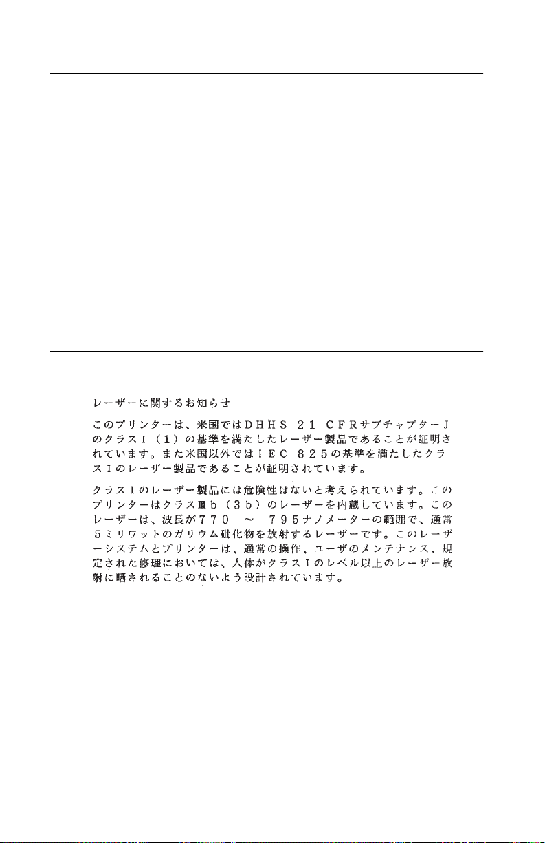
Japanese Laser Notice
xviii Service Manual
Page 19
4040
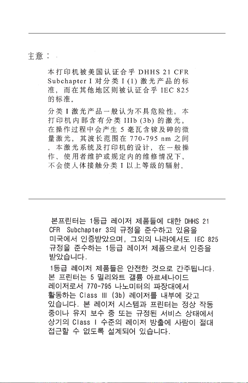
Chinese Laser Notice
Korean Laser Notice
Notices and Safety Information xix
Page 20

4040
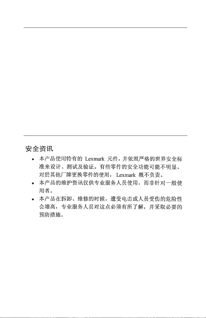
Safety Information
•
This product is designed, tested and approved to meet strict
global safety standards with the use of specific Lexmark
components. The safety f eatures of some parts may not always
be obvious. Lexmark is not responsible for the use of other
replacement parts.
•
The maintenance information for this product has been
prepared for use by a professional service person and is not
intended to be used by others.
•
There may be an increased risk of electric shock and personal
injury during disassembly and servicing of this product.
Professional service personnel should understand this and take
necessary precautions.
Consignes de Sécurité
•
Ce produit a été conçu, testé et approuvé pour respecter les
normes strictes de sécurité globale lors de l'utilisation de
composants Lexmark spécifiques. Les caractéristiques de
sécurité de certains éléments ne sont pas toujours évidentes.
Lexmark ne peut être tenu responsable de l'utilisation d'autres
pièces de rechange.
•
Les consignes d'entretien et de réparation de ce produit
s'adressent uniquement à un personnel de maintenance
qualifié.
•
Le démontage et l'entretien de ce produit pouvant présenter
certains risques électriques, le personnel d'entretien qualifié
devra prendre toutes les précautions nécessaires.
xx Service Manual
Page 21

4040
Norme di sicurezza
•
Il prodotto è stato progettato, testato e approvato in conf ormità a
severi standard di sicurezza e per l’utilizzo con componenti
Lexmark specifici. Le caratteristiche di sicurezza di alcune parti
non sempre sono di immediata comprensione. Lexmark non è
responsabile per l’utilizzo di parti di ricambio di altri produttori.
•
Le informazioni riguardanti la manutenzione di questo prodotto
sono indirizzate soltanto al personale di assistenza autorizzato.
•
Durante lo smontaggio e la manutenzione di questo prodotto, il
rischio di subire scosse elettriche e danni alla persona è più
elevato. Il personale di assistenza autorizzato, deve, quindi,
adottare le precauzioni necessarie.
Sicherheitshinweise
•
Dieses Produkt und die zugehörigen Komponenten wurden
entworfen und getestet, um beim Einsatz die weltweit gültigen
Sicherheitsanforderungen zu erfüllen. Die sicherheitsrelev anten
Funktionen der Bauteile und Optionen sind nicht immer
offensichtlich. Sofern Teile eingesetzt werden, die nicht von
Lexmark sind, wird von Lexmark keinerlei Verantwortung oder
Haftung für dieses Produkt übernommen.
•
Die Wartungsinformationen für dieses Produkt sind
ausschließlich für die Verwendung durch einen
Wartungsfachmann bestimmt.
•
Während des Auseinandernehmens und der Wartung des
Geräts besteht ein zusätzliches Risiko eines elektrischen
Schlags und körperlicher Verletzung. Das zuständige
Fachpersonal sollte entsprechende Vorsichtsmaßnahmen
treffen.
Notices and Safety Information xxi
Page 22

4040
Pautas de Seguridad
•
Este producto se ha diseñado, verificado y aprobado para
cumplir los más estrictos estándares de seguridad global
usando los componentes específicos de Lexmark. Puede que
las características de seguridad de algunas piezas no sean
siempre evidentes. Le xmark no se hace responsable del uso de
otras piezas de recambio.
•
La información sobre el mantenimiento de este producto está
dirigida exclusivamente al personal cualificado de
mantenimiento.
•
Existe mayor riesgo de descarga eléctrica y de daños
personales durante el desmontaje y la reparación de la
máquina. El personal cualificado debe ser consciente de este
peligro y tomar las precauciones necesarias.
Informações de Segurança
•
Este produto foi concebido, testado e aprovado para satisfazer
os padrões globais de segurança na utilização de componentes
específicos da Lexmark. As funções de segurança de alguns
dos componentes podem não ser sempre óbvias. A Lexmark
não é responsável pela utilização de outros componentes de
substituição.
•
As informações de segurança relativas a este produto
destinam-se a profissionais destes serviços e não devem ser
utilizadas por outras pessoas.
•
Risco de choques eléctricos e ferimentos graves durante a
desmontagem e manutenção deste produto. Os profissionais
destes serviços devem estar avisados deste facto e tomar os
cuidados necessários.
xxii Service Manual
Page 23
4040
Informació de Seguretat
•
Aquest producte està dissenyat, comprovat i aprovat per tal
d'acomplir les estrictes normes de seguretat globals amb la
utililització de components específics de Lexmark. Les
característiques de seguretat d'algunes peces pot ser que no
sempre siguin òbvies. Lexmark no es responsabilitza de l'us
d'altres peces de recanvi.
•
La informació pel manteniment d’aquest producte està
orientada exclusivament a professionals i no està destinada a
ningú que no ho sigui.
•
El risc de xoc elèctric i de danys personals pot augmentar
durant el procés de desmuntatge i de servei d’aquest producte.
El personal professional ha d’estar-ne assabentat i prendre les
mesures convenients.
Pautas de Seguridad xxiii
Page 24
4040
xxiv Service Manual
Page 25

4040
Preface
This manual is divided into the following chapters:
•
“General Information” contains a general description of the
printer and the maintenance approach used to repair it. Special
tools, test equipment, and options are listed.
•
“Diagnostic Information” contains error code table, symptom
table, and service checks used to isolate failing field replaceable
units (FRUs).
•
“Diagnostic Aids” contains tests and checks used to locate or
repeat symptoms of printer problems.
•
“Repair Information” provides instructions for making printer
adjustments and removing and installing FRUs.
•
“Locations” uses illustrations to identify the major components
and test points on the printer.
•
“Preventive Maintenance” contains safety inspection guidelines,
lubrication specifications, and maintenance information to
prevent problems and maintain optimum performance.
•
“Parts Catalog” contains illustrations and part numbers for
individual FRUs.
Preface
xxv
Page 26

4040
1. General Information
The OptraTM N, model 4040 is a 600 dpi laser printer designed to
attach to IBM-compatible PC’s and to most types of computer networks.
Options
The following options are available. Some options are not available
in every country. Contact your point of purchase for options available
in your country.
2000-Sheet Paper Deck
Duplexer
Envelope Feeder
Memory upgrade options of 2MB, 4MB, 8MB, 16MB and 32MB.
Flash memory options of 1MB, 2MB and 4MB
Integrated network options
Token-Ring
Ethernet
Internal disk option
LocalTalk
Maintenance Approach
The diagnostic information in this manual leads you to the correct
field replaceable unit (FRU) or part. Use the error code charts,
symptom index, service checks, and diagnostic aids to determine
the symptom and repair the failure.
This printer can be serviced without being connected to a host computer.
After you complete the repair, perform tests as needed to verify the
repair.
1-1
Page 27

4040
Tools
The removal and adjustment procedures described in this manual
require the following tools and equipment:
•
Magnetic tip Phillips screwdrivers large and small
•
Flat-blade screwdriver
•
Analog volt ohmmeter (a digital volt ohmmeter may also be
used).
•
Oiler
•
Grease
•
Cleaning tissue
•
Magnifier
•
Gloves
•
Ruler
Refer to the parts catalog for part numbers of special tools. When
taking voltage readings, always use frame ground unless another
ground is specified.
General Information 1-2
Page 28

4040
Abbreviations
ASIC Application-Specific Integrated Circuit
CSU Customer Setup
DRAM Dynamic Random Access Memory
EEPROM Electrically Erasable Programmable Read-
Only Memory
EP Electrophotographic Process
ESD Electrostatic Discharge
FRU Field Replaceable Unit
HVPS High Voltage Power Supply
LAN Local Area Network
LASER Light Amplification by Stimulated Emission
of Radiation
LCD Liquid Crystal Display
LED Light-Emitting Diode
LVPS Low Voltage Power Supply
NVRAM Nonvolatile Random Access Memory
OEM Original Equipment Manufacturer
PICS Problem Isolation Charts
PIXEL Picture Element
POR Power-On Reset
POST Power-On Self Test
PQET Print Quality Enhancement Technology
RIP Raster Image Processor
ROS Read-Only Storage
SRAM Static Random Access Memory
UPR Used Parts Replacement
VAC Volts alternating current
VDC Volts direct current
1-3
Page 29

4040
2. Diagnostic Information
Diagnostic Approach
This printer can be serviced without being connected to a host computer.
This printer displays both operator correctable errors and service
errors on the front (operator) panel. In addition, there are two tests
available from the base machine and the optional 2000 sheet paper
deck that allow you to b ypass the controller card. You can use these
basic engine function tests to eliminate potential software problems.
See “Diagnostic Aids” on page 3-1.
The diagnostic information in this chapter should lead you to the failing part. Before you replace an entire assembly, determine if just the
defective part is available in the parts catalog. Some diagnostic procedures indicate the parts catalog location of the part to be replaced
by including the assembly number and reference number in parenthesis. Use the error code tables, symptom table, service checks
and the diagnostic aids chapter to determine the symptom and
repair the failure. After you complete the repair, perform the appropriate tests to verify the repair.
Start
Initial Check
Before you start troubleshooting, check the following:
Installation Environment
•
The power supply line voltage is plus or min us 10% of the rated
line voltage.
•
The printer is securely installed on a level surface in a well-ventilated place.
Diagnostic Information 2-1
Page 30

4040
•
The room temperature is between 10 and 32.5 ° C, and the relative humidity between 20 and 80%.
•
Avoid sites generating ammonia gas, high temperature or high
humidity (near water faucets, kettles, humidifiers), cold spaces,
near open flames, and dusty areas.
•
Avoid sites exposed to direct sunlight.
Print Paper Checks
•
Be sure the recommended paper for this printer is being used.
•
Check the paper for dampness. Make a trial print with paper
from a newly opened package, and check the result.
EP Cartridges
If blank spots appear on an output image, there is a chance that the
toner is not evenly mix ed. Rock the toner cartridge and then make a
print to see if the toner has evenly mixed.
Other
If a packaged EP cartridge is opened soon after being moved from a
cold room to a warm room, condensation will appear inside the cartridge; this can cause various image defects. In such cases, be sure
to instruct the customer that it is necessary to leave the cartridge
sealed for one to two hours at room temperature to allow it to acclimatize.
2-2
Page 31

4040
Troubleshooting
Use the error message tables, symptom table, and service checks,
in this chapter and the diagnostic aids in Chapter 3 to diagnose a
failure.
If the operator panel is blank, black, has diamonds across the display, or appears unusual, unplug the controller card and run “Basic
Engine Test” on page 3-2. Go to Chapter 3 “Diagnostic Aids” to diag-
nose this problem because the operator panel or controller card may
have a defect.
If your machine makes it through POST without an error but you
have a symptom, go to the appropriate symptom table, locate your
symptom and take the appropriate action.
If an error is displayed, locate it in the following “Error Message
Tables” and take the appropriate action.
If an error message appears while you are working on the printer , go
to the error message table and take the indicated action.
Diagnostic Information 2-3
Page 32

4040
Error Code/Message Tables
Service Error Codes
Error Symptom or Message Action
900 Unrecoverable Software
920
922
923 Fuser Error, Fuser is too hot
924 Fuser Error, Wrong voltage Go to the “Fuser (Wrong Typ e)
927 Fan stalled Go to the “Fan Motor Service
931
932
933
934
935 Printhead Error If the main motor (MT1) (2-7) runs
Error
Fuser Error, Fuser lamps do
not come on during POR, or
fuser lamps come on but do
not reach operating temperature after 180 seconds.
or warming up abnormally.
Printhead Errors Check the printhead connectors.
Refer to the operator manual
Go to the “Fuser (Temp erature
Low) Service Check (920/922)” on
page 2-23.
Go to the “Fuser (Abnormal Tem-
perature) Service Check (923)” on
page 2-22.
Service Check (924)” on page
2-24.
Check (927)” on page 2-19.
Replace the printhead if necessary. If you still have a failure,
replace the system board (4-9).
during POR, replace the printhead
(4-32). If the motor does not run
during POR, check the connectors
to the motor.
2-4
If necessary, replace the motor
and POR the machine. If you still
have a failure, replace the system
board (4-9).
Page 33

4040
Error Symptom or Message Action
938 Paper Deck Option Card, No
response
939 System Board Error Be sure all cables, SIMM, and
941 Incorrect CHECKSUM
(EPROM)
944
945
946
947
950
953
960 Memory Error, Base DRAM
961 Memory Error, Option
Controller Card Failure Replace the controller card (19-2).
(J3)
DRAM (J2)
Check all connectors on the paper
deck board and be sure all doors
are securely closed. POR the
machine. If you still have a failure,
replace the paper deck option
controller card (29-1). If you still
have a failure, replace the paper
deck driver board (23-41).
option controller riser card are correctly installed, then POR the
machine. If you still have a failure,
replace the system board (4-9).
Replace the EPROM controller
card (J8) (19-3).
Be sure to move the controller
SIMM, memory SIMMS, and
option cards from the old board to
the new one.
Replace memory SIMM J3 (19-
10) on the controller card.
Replace optional memory SIMM
J2 on the controller card.
97X INA Failure Be sure the controller riser card
and the INA are properly installed.
Replace the INA. If you still have a
failure, replace the system board
(4-9).
Diagnostic Information 2-5
Page 34

4040
Error Symptom or Message Action
977 Network Card Error The system processor has
detected an INA card is installed
but cannot communicate with it.
The X after the card indicates
which one has the problem. Network card 1 will always ref er to the
INA in the bottom slot and Network card 2 will always ref er to the
INA card in the top slot.
Be sure the controller card riser
card is properly installed.
980 Device Error, 2000- sheet
paper deck motor.
982 Device Error, Lifter malfunc-
tion in the multipurpose tray.
983 Device Error, Lifter malfunc-
tion, 200-sheet paper deck.
990 Service Duplex Option Be sure the duplex registration
Be sure the motor is securely
installed. If necessary, replace
motor MT31 (26-3).
Be sure J214 is securely installed
to the system board. Be sure the
connectors on the multipurpose
tray board are installed correctly.
If necessary, replace the lifting
plate solenoid SL2 (14-6). If you
still have a failure, replace the
multipurpose tray board (14-20).
Be sure the lifter plate clutch
(CL31) connector (J206) on the
paper deck driver board is
securely installed. Check for broken parts. If necessary replace
the paper deck lifter clutch (26-5).
motor cable is installed correctly.
Check for broken registration
parts. If necessary, replace the
duplex registration motor SMT22
(22-22).
2-6
Page 35

4040
Operator Codes
The following code numbers are operator instructions and messages. In some cases, no action is required; others are operator-correctable; others may require service. An error code may require up
to two minutes to appear. Some symptoms may not generate an
error code. Locate your code in the table and take the appropriate
action.
Code Message or Symptom Action
20
21
22
23
25
27 Change Envelope No service required, refer to oper-
27 Change Paper, Possible
27 Change Paper, Possible
28 Load Envelope Feeder Be sure the correct envelope size
Paper Jam, Clear All Paper
Possible error locations:
20 Tray 1
20 Tray 2
20 Tray 3
21 Input
21 Input Feeder (envelope)
21 Input Multipurpose Tray
22 Fuser
23 Top Output
25 Duplex
locations:
27 Tray 1
27 Tray 2
location:
27 Tray 3
Clear all paper jams and POR the
machine. If the error remains, go
to the “Paper Jam Sensor Service
Check” on page 2-45.
If the paper sensors are good go
to the “Paper Feed Symptom
Table” on page 2-12 or the “Paper
Deck Symptom Table” on page
2-15 and check for mechanical
problems.
ator manual.
Be sure the correct paper size is
installed.
Go to the “Paper Jam 27, Paper
Size/Change Paper” on page
2-49.
Go to the “Paper Deck Lifting
Plate Service Check” on page
2-53.
and weight is installed. Replace
PS931 paper sensor (21-7) on the
envelope driver board.
Diagnostic Information 2-7
Page 36

4040
Code Message or Symptom Action
29 Output Bin Full, top bin only Remove the paper from the output
face-down bin. Check and
replace if necessary:
• Paper Full Lever (16-4)
• Switch Sensor Board (4-18)
32 Print Cartridge Missing Be sure the print cartridge is prop-
erly installed. Clean or replace the
high voltage power supply contacts (7-2).
37 Insufficient Memory No service required, refer to oper-
38 Memory Full No service required, refer to oper-
39 Complex Page No service required, refer to oper-
51 Defective Flash Go to Diagnostic Aids and run the
52 Flash Full No service required, refer to oper-
54 Serial Port Disabled No service required, refer to oper-
56 Parallel Port Disabled No service required, refer to oper-
57 Check Tray 3 Be sure the following are correct:
ator manual.
ator manual.
ator manual.
device tests. Replace Flash SIMM
J-7, on the controller card, if necessary.
ator manual.
ator manual.
ator manual.
• Tray 3, Paper drawer closed
• Power cord plugged in
• Option controller is installed
• Option controller signal cab le is
completely installed.
• If you still have no power to the
paper deck, go to the “Paper
Deck Power Input Service
Check” on page 2-57.
2-8
Page 37

4040
Code Message or Symptom Action
58 Duplex not attached Be sure the duplexer is securely
latched into the printer.
POR to reset the printer.
59 Print Job on Disk No service required, refer to oper-
63 Unformatted Disk Format the disk. Go to “Diagnostic
64 Defective Disk Replace the defective disk. Go to
80 Scheduled Maintenance No service required, refer to oper-
ator manual.
Aids” on page 3-1 and run the
device tests.
“Diagnostic Aids” on page 3-1 to
format the new disk .
ator manual.
The Maintenance Kit must be
ordered and installed by the customer. P art numbers can be found
in the User’s Guide.
This message appears each time
the printer is turned on.
Diagnostic Information
The diagnostic information in this chapter is divided as follows:
•
Base Machine Service Checks
•
Print Quality Service Checks
•
Paper Feed Service Checks
•
Paper Deck Service Checks
•
Paper Deck Paper Feed Service Checks
If you think your symptom is caused by a print quality failure go to
the “Print Quality Symptom Table” on page 2-11.
If you think your symptom is caused by a paper f eed f ailure, go to the
“Paper Feed Symptom Table” on page 2-12.
If you think your problem is caused by a malfunction in the paper
deck go to “Paper Deck Service Checks” on page 2-53.
Diagnostic Information 2-9
Page 38

4040
If you think your symptom is caused by a paper feed problem in the
paper deck go to “Paper Dec k Paper Feed Service Checks” on page
2-58.
If you think your symptom is caused by any other malfunction, go to
the “Other Malfunction Symptom Table” on page 2-13.
2-10
Page 39

4040
Symptom Tables
Print Quality Symptom Table
Symptom Action
Black Page Go to “Black Page Service Check:”
on page 2-30.
Blank Spots Go to “Blank Spots Service Check”
Blank Page Go to “Blank Page Service Check”
Dark Image Go to “Dark Image Service Check”
Dirt on back of paper Go to the “Dirt on Back of Paper
Dirty Image Go to the “Dirty Image Service
Distortion Go to “Distorted Print Service
Light Image Go to “Light Image Service Check”
Poor Fusing Go to “Poor Fusing Service Check”
Sharp Black Horizontal Lines Go to “Sharp Black Horizontal
Smudged Horizontal Bands Go to “Smudged Horizontal Bands
on page 2-30.
on page 2-31.
on page 2-32.
Service Check” on page 2-32.
Check” on page 2-33.
Check” on page 2-33.
on page 2-34.
on page 2-35.
Lines Service Check” on page
2-35.
Service Check” on page 2-36.
Vertically Dots in a Line Go to “Light Image Service Check”
Vertical Streaks/Lines Go to “Vertical Streaks/Lines Ser-
White Horizontal Lines Go to “White Horizontal Lines Ser-
on page 2-34.
vice Check” on page 2-37.
vice Check” on page 2-37.
Diagnostic Information 2-11
Page 40

4040
Symptom Action
White Vertical Lines Go to “White Vertical Lines Service
Check” on page 2-38.
Paper Feed Symptom Table
Symptom Action
Paper Jam in Pick-up Assembly Go to “Pick-Up Assembly Paper
Paper Jam in Fuser and Delivery
Assembly
Paper Jam in Duplexing Assembly Go to “Paper Jam 25, Duplex” on
Paper Jam in Envelope Feeder Go to “Envelope Feeder Paper
Multiple Paper Feed Go to “Multiple Paper F eed Service
Wrinkled Paper Go to “Wrinkled Paper Service
Bent Leading Edge of Paper Go to “Bent Leading Edge of P aper
Skewed Paper Go to “Paper Skew Service Check”
Jams Service Check” on page
2-51.
Go to “Fuser and Delivery, Paper
Jams Service Check” on page
2-43.
page 2-49.
Jams Service Check” on page
2-42.
Check” on page 2-44.
Check” on page 2-52.
Service Check” on page 2-40.
on page 2-50.
2-12
Page 41

4040
Other Malfunction Symptom Table
Symptom Action
Printhead Malfunction
Electrical Assembly Fan (FM3)
Failure
Faulty Main Motor
Fuser Failure (Abnormal Temperature)
Fuser Failure (Abnormal Warmup/Temperature Low)
Fuser Failure (Wrong Type)
Fuser Fan (FM4) Failure
Fuser/Printhead Fan (FM2) F ailure
Horizontal Registration Guide
Failure (Duplexing Installed)
Go to the “Printhead Service
Check” on page 2-28.
Go to “Electrical Assembly Fan
(FM3) Check” on page 2-21.
Go to “Main Motor Service Check”
on page 2-25.
Go to “Fuser (Abnormal Tempera-
ture) Service Check (923)” on page
2-22.
Go to “Fuser (Temperature Low)
Service Check (920/922)” on page
2-23.
Go to “Fuser (Wrong Type) Service
Check (924)” on page 2-24.
Go to “Fuser Fan (FM4) Check” on
page 2-21.
Go to the “Fuser/Printhead Fan
(FM2) Check” on page 2-20.
Go to “Duplex Horizontal Registra-
tion Guide Service Check” on page
2-18.
Printhead/Laser Malfunction
Lifting Plate Failure (Multi-purpose Tray)
No AC Power Input (Dead
Machine)
No DC Power Input (Dead
Machine)
No Paper Pick-Up (From Multipurpose Tray)
Go to the “Printhead/Laser Service
Check” on page 2-28.
Go to the “Lifting Plate (Multipur-
pose Tray) Service Check” on page
2-25.
Go to “AC Power Input Service
Check” on page 2-16.
Go to “DC Power Input Service
Check” on page 2-17.
Go to “Paper Pick-Up from Multi-
purpose Tray Service Check” on
page 2-27.
Diagnostic Information 2-13
Page 42

4040
Symptom Action
No Paper Pick-Up from Upper
or Lower Cassette
No Paper Pick-Up from Envelope Feeder
Poor Output from High-Voltage
Power Supply
Power Supply Fan (FM1) Failure
Registration Roller Does Not
Rotate
Printhead/Scanner Motor Malfunction
Operator Panel Does Not Operate
Properly
Go to “Paper Pick-Up from Cas-
settes Service Check” on page
2-26.
Go to “Paper Pick-Up from Enve-
lope Feeder Service Check” on
page 2-26.
Go to “High-Voltage Power Supply
Output Service Check” on page
2-24.
Go to “Fan Motor Service Check
(927)” on page 2-19.
Go to “Registration Roller Service
Check” on page 2-29.
“Printhead/Scanner Motor Service
Check” on page 2-29.
Go to the Diagnostic Aids Chapter
and run the LCD and Button tests.
If the tests fail, replace the operator
panel. If the display has diamonds
on it or is blank, run the basic
engine test. If the test completes
and the panel remains blank,
replace the operator panel (1-22). If
diamonds remain, check the SIMM
(19-3) for proper installation. If you
still have a problem, replace the
controller card (19-2).
If your machine beeps 5 times and
the screen is blank or all diamonds,
replace the operator panel.
No Side Output Bin Operation Check and replace the face-up
solenoid assembly parts (asm. 6).
Replace the face-up solenoid if
necessary.
2-14
Page 43

4040
Paper Deck Symptom Table
Symptom Action
No power Go to the “Paper Deck Power Input
Wrinkled paper Go to the “Paper Deck Wrinkled
Bent leading paper edge Go to the “P aper Dec k Bent Leading
Paper skew Go to the “Paper Deck Paper Skew
Left edge registration failure Go to the “Paper Deck Left Edge
Paper doesn’t pick-up from the
paper deck
Paper doesn’t exit paper registration roller.
Paper doesn’t exit paper deck ,
jam in feed roller.
Multiple sheets of paper feeding. Go to the “Paper Deck Multiple
Paper deck doesn’t lift properly Go to the “Paper Deck Lifting Plate
Service Check” on page 2-57.
Paper Service Check” on page 2-60.
Edge Service Check” on page 2-58.
Service Check” on page 2-60.
Registration Service Check” on page
2-59.
Go to the “Paper Deck Paper Pick-
Up Service Check” on page 2-55.
Go to the “Paper Deck Registration
Roller Service Check” on page 2-58.
Go to the “Paper Deck Feed Roller
Service Check” on page 2-53.
Paper Feed Service Check” on page
2-59.
Service Check” on page 2-53.
Paper deck does not sense paper
size, paper full, or surface
obstruction.
Faulty paper deck drive motor Go to the “Paper Deck Motor Service
Go to the “Paper Deck Lifting Plate
Service Check” on page 2-53.
Check” on page 2-55.
Diagnostic Information 2-15
Page 44

4040
Base Machine Service Checks
AC Power Input Service Check
FRU Action
1
Voltage The correct voltage may not be present at the
outlet. Inform the customer that the correct
line voltage is not available at the outlet.
2
Power Cord
The power cord may not be firmly plugged into
the printer, the paper deck and the outlet.
3 Circuit Breaker
Push the power plugs in firmly
The circuit breaker may be off. Remove the
.
power supply. Press the circuit breaker button
to set the circuit breaker on.
4 Power Switch The power switch may be defective. Remove the
5
Low Voltage
Power Supply
power supply. Measure the resistance between the
two terminals of the power switch by applying the
tester probes to the terminals. The resistance must
be zero when the power is turned on, and infinity
when the switch is turned off. If it is not, replace the
power supply.
The ac power line in the low voltage power
supply may be defective. Replace the power
supply.
If ac power is present and the machine is dead go to the “DC Power
Input Service Check” on page 2-17.
2-16
Page 45

4040
DC Power Input Service Check
FRU Action
1
AC Power If the ac power is not present, go to “AC Power
Input Service Check” on page 2-16.
2
Overcurrent/
Overvoltage
Detection
Circuit
3
Fuse
4
Power Supply
5 System Board
The overcurrent/overvoltage detection circuit
may be active. If the problem does not disappear when the power switch is turned off and
on again, find the cause of activation of the
overcurrent/over voltage detection circuit of
the power supply. T urn the power s witch off for
2 minutes then turn it on again.
The fuse may be blown. Remove the power
supply and replace the fuse (5-15)
The power supply may be def ectiv e. Turn the power
switch off and remove connector J204 from the system board. Plug in the power cable and turn the
power switch on. Measure the DC power supply
output of connector J204. Do not short the connector. If the correct value is not outout, replace the
power supply (5-10)
.
Turn the power switch off. Check the wiring
from the system board J204 and the power
supply. If they are normal, replace the system
board (4-9)
.
Diagnostic Information 2-17
Page 46

4040
Duplex Horizontal Registration Guide Service Check
FRU Action
1
Connectors The horizontal registration guide home posi-
tion sensor signal line and horizontal registration motor drive signal line connectors may be
loose. Reconnect connectors J2005 and
J2006 on the duplexing driver board.
2
Gears Gears may be damaged. Replace any dam-
aged gears.
3
Sensor
(PS23)
The horizontal registration guide home position sensor (PS23) may be defective. Check
and replace as required (22-53).
4
Horizontal
Registration
Motor
5
Duplexing
Driver Board
The horizontal registration motor may be
defective. Replace the horizontal registration
motor (22-22).
The duplexing driver board could be defectiv e.
Replace the duplexing driver board (22-14).
2-18
Page 47

4040
Fan Motor Service Check (927)
Be sure the power is on, then check the air flow from each fan to
determine which fan is failing. Go to the appropriate fan check
below.
Diagnostic Information 2-19
Page 48

4040
Power Supply Fan (FM1) Check
FRU Action
1
Connector The FM1 drive signal line connector could be
loose. Reconnect connector J208 on the system board.
2
Power Supply Fan
The power supply fan could be defective. Disconnect connector J208 on the system board.
Turn the power switch on and measure the
voltage between connector J208-1 (FAN1D)
and J208-3 (GND) on the system board. If the
voltage changes from 0 to more than 18 V,
replace the power supply fan (5-11).
3
System
The system board could be defective (4-9).
Board
Fuser/Printhead Fan (FM2) Check
FRU Action
1
Connector The FM2 drive signal line connector could be
loose. Reconnect connector J216 on the system board.
2
Fuser/Printhead Fan
The printhead fan could be defective. Disconnect connector J216 on the system board.
Turn the power switch on and measure the
voltage between connector J216-1 (FAN2D)
and J216-3 (GND) on the system board. If the
voltage changes from 0 to more than 18 V,
replace the printhead fan (4-29).
3
System
The system board could be defective (4-9).
Board
2-20
Page 49

4040
Electrical Assembly Fan (FM3) Check
FRU Action
1
FM3 Drive
Signal Line
Connector
2
Electrical
Unit Fan
The FM3 drive signal line connector could be
loose. Reconnect connector J210 on the system board and connectors J12 and J13.
The electrical unit fan could be defective. Disconnect connector J210 on the system board.
Turn the power switch on and measure the
voltage between connector J210-1 (FAN3D)
and J210-3 (GND) on the system board. If the
voltage changes from 0 to more than 18 V,
replace the electrical assembly fan (5-7).
3
System
The system board could be defective (4-9).
Board
Fuser Fan (FM4) Check
FRU Action
1
Connector The FM4 drive signal line connector may be
loose. Reconnect connector J225 on the system board and connectors J25 and J26.
2
Fuser Fan The fuser fan may be defective. Disconnect
connector J225 on the system board. T urn the
power switch on and measure the voltage
between connector J225-1 (FAN4D) and
J225-3 (GND) on the system board. If the voltage changes from 0 to more than 18 V.
replace the fuser fan (16-7).
3
System
Board
The system board could be defective (4-9).
Diagnostic Information 2-21
Page 50

4040
Fuser (Abnormal Temperature) Service Check (923)
FRU Action
1
Thermistor The thermistor could be shorted. Turn the
power off and remove the fuser assembly.
Measure the resistance between the fuser
connector J50B-2 (FSRTH) and J50B-3
(GNDTH). The connector J50B is the lower
terminal of the left connector. If the resistance
is 1k Ohm or less, check the wiring from connector J222-5 and J222-6 on the system
board to the thermistor. If it is normal, replace
the thermistor (18-23).
2Fuser
3
System
Board
The fuser drive circuit in the power supply is
defective. Replace the power supply (5-10).
The system board could be defective (4-9).
2-22
Page 51

4040
Fuser (Temperature Low) Service Check (920/922)
FRU Action
1
Thermistor The thermistor may be dirty. If the thermistor
contact area of the fuser upper roller is dirty,
clean it.
The thermistor may not be installed correctly.
If the thermistor is not evenly contacting the
fixing upper roller, re-install the thermistor correctly.
2 Thermistor
Wire
3
Main Heater
Wire
4
Sub Heater
Wire
5
Thermoswitch
The thermistor wire may be broken. Turn the
power off and remove the fuser assembly.
Measure the resistance between fuser connector J50B-2 (FSRTH) and J50B-3
(GNDTH). If the resistance is not between
150k Ohms and 290k Ohms (normal temperature), check the wiring from connector J222 on
the system board to the thermistor. If it is normal, replace the thermistor (18-23).
The main heater wire could be broken.
Remove the fuser. If there is no continuity
between fuser connector J50-3 (FSRN1: the
upper right terminal of the left connector) and
J51-4 (FSRN2: the upper right terminal of the
right connector), replace the main heater (182A).
The sub heater wire may be broken. Remove
the fuser assembly. If there is no continuity
between fuser connector J50-4 (FSRL1: the
lower right terminal of the left connector) and
J51-3 (FSRL2: the lower right terminal of the
right connector), replace the fuser lamp (182A).
The thermoswitch may be open. Remove the
fuser assembly and wiring cover. If there is no
continuity between thermoswitch connectors,
replace the thermoswitch (18-3).
6
System
Board
The system board could be defective (4-9).
Diagnostic Information 2-23
Page 52

4040
Fuser (Wrong Type) Service Check (924)
FRU Action
1
Fuser The rated voltage of the fuser may not match
the power supply voltage. Replace the fuser
(18-1).
2
Power Supply
The type detection circuit in the power supply
may be defective. Replace the power supply
(5-10).
3
System
The system board could be defective (4-9).
Board
High-Voltage Power Supply Output Service Check
FRU Action
1
High-Voltage
Contacts
A terminal of the high-voltage contacts (7-2)
could be dirty or burned out. Clean the terminals of the high-voltage contact. Replace if it is
burned out.
2
3
2-24
High-Voltage
Power Supply Board
System
Board
The high-voltage power supply board could be
defective. Replace the high-voltage power
supply (Asm. 7).
The system board could be defective (4-9).
Page 53

4040
Lifting Plate (Multipurpose Tray) Service Check
FRU Action
1
Lifting Plate
Drive Assem-
The lifting plate drive assembly could be
defective. Replace any damaged parts.
bly
2
Lifting Plate
Position Sensor (PS1302)
The lifting plate position sensor could be
defective. Check the sensor (PS1302) by
measuring the voltage at J214-3 and J214-6
(+5 V). You should get a lower reading when
the lifter plate rises. If it is defective replace
the multipurpose tray board (14-20).
3
Lifting Plate
Solenoid
(SL2)
The lifting plate solenoid could be defective.
Disconnect lifting plate solenoid connector
J1302. Measure the resistance between connectors J1302-1 and J1302-2 on the cable
side. If it is not about 100 Ohms replace the
lifting plate solenoid (14-6).
4
System
The system board could be defective (4-9).
Board
Main Motor Service Check
FRU Action
1
Main Motor
Drive Line
Connectors
The main motor drive line connectors could be
loose. Reconnect connector J12 of the main motor
and connector J218 on the system board.
2
Door Switch
3
Main Motor
(MT1)
4
System
Board
The door switch in the switch/sensor board could
be defective. Remove connectors J205 and J221
on the system board. If J205-3(+24 V dc) and J2211(+24 VB) on the cable side do not conduct when
the door switch (SW1401) is on, replace the switch/
sensor board (4-18).
The main motor could be defective. If it does not
rotate during POR and no error codes appear,
replace it (2-7).
The system board could be defective (4-9).
Diagnostic Information 2-25
Page 54

4040
Paper Pick-Up from Envelope Feeder Service Check
FRU Action
1
Controller
Card
The controller card could be defective. Run
paper feed test in Diagnostic Aids to determine
which paper path is causing the problem.
envelope is picked up correctly from the envelope feeder, replace the controller card (19-2).
2
Gears Gears could be damaged. Remove the enve-
lope feeder and check the gears. Replace any
damaged gears.
3
Envelope
Feeder Pickup Motor
(SMT11)
4
Envelope
Feeder Driver
Board
5
System
The envelope feeder pick-up motor could be
defective. Run the paper feed test in Diagnostic Aids to rotate the envelope feeder pick-up
motor. If it does not rotate replace it (21-27).
The envelope feeder driver board could be
defective. Replace the envelope feeder driver
board (21-7).
The system board could be defective (4-9).
Board
Paper Pick-Up from Cassettes Service Check
FRU Action
the
If the
1
2
3
2-26
Controller
Card
Pick-up
Drive Assembly
Pick-up
Motor
(SMT1)
The controller card could be defective. Use
the paper feed test in Diagnostic Aids to make
a test print from the cassette with a paper
pick-up failure. If the paper is picked up correctly from the cassette, replace the controller
card.
The pick-up drive assembly could be damaged. Remove the pick-up unit and replace
any damaged parts.
The pick-up motor could be defectiv e . Use the
the paper feed test in Diagnostic Aids to rotate
the paper pick-up motor. If it does not rotate,
replace it (11-46).
Page 55

4040
FRU Action
4
Cassette
Pick-up Solenoid (SL1)
The cassette pick-up solenoid could be defective. Remove the pick-up unit, and disconnect
cassette pick-up solenoid connector J1203
from the pick-up board. Measure the resistance between connectors J1203-1 and
J1203-2 on the cable side. If it is not about
155 Ohms, replace the cassette pick-up solenoid (11-56).
5
6
Pick-up
Board
System
The pick-up board could be defectiv e. Replace
the pick-up board (11-41).
The system board could be defective (4-9).
Board
Paper Pick-Up from Multipurpose Tray Service Check
FRU Action
1
Controller
Card
2
Gears Gears could be damaged. Remove the man-
The controller card could be defective . Make a
test print from the multipurpose tray using the
paper feed test in Diagnostic Aids. If the paper
is picked up correctly, replace the controller
card (19-2).
ual feed pick-up assembly and check the
gears. Replace any damaged gears.
3
Manual Feed
Clutch (SL3)
4
System
Board
The manual feed clutch could be defective.
Remove the manual feed pick-up assembly
and disconnect manual feed clutch connector
J1303 from the multipurpose tray board. Measure the resistance between connectors
J1303-1 and J1303-2 on the cable side. If it is
not about 155 Ohms, replace the manual feed
clutch (14-5).
The system board could be defective (4-9).
Diagnostic Information 2-27
Page 56

4040
Printhead Service Check
Condensation could cause this problem. Leave the printer running
for 10 to 20 minutes.
FRU Action
1
Printhead
Board Signal
Line Connec-
The printhead signal line connector could be
loose. Reconnect connector J6 on the printhead board and J206 on the system board.
tor
2
Printhead The printhead assembly could be defective.
(The BD signal is not output correctly.)
Replace the printhead assembly (4-32).
3
System
The system board could be defective (4-9).
Board
Printhead/Laser Service Check
FRU Action
1
Connectors
2
Printhead The printhead (laser driver circuit) could be
The laser drive signal line connectors may be
loose. Reconnect connector J1001 on the laser
driver board and connector J202 on the system
board.
defective. Replace the printhead (4-32).
3
2-28
System
Board
The system board could be defective (4-9).
Page 57

4040
Printhead/Scanner Motor Service Check
FRU Action
1
Connectors
The scanner motor drive line connectors could
be loose. Reconnect connector J1 on the
scanner driver board, connector J18, and connector J207 on the system board
2
Printhead/
Scanner
Motor Driver
The scanner motor driver could be defective.
Check the connectors on the printhead. Run a
test print. If you still have the problem, replace
the printhead (4-32).
3
System
The system board could be defective (4-9).
Board
Registration Roller Service Check
FRU Action
1
Gears Gears could be damaged. Check and replace
any damaged gears.
2
Registration
Clutch (CL1)
The registration clutch could be defectiv e. Disconnect registration clutch connector J17.
Measure the resistance between connectors
J17-1 and J17-2 on the cable side. If it is not
about 210 Ohms, replace the registration
clutch (12-4).
.
3
System
Board
The system board could be defective (4-9).
Diagnostic Information 2-29
Page 58

4040
Print Quality Service Checks
Black Page Service Check:
FRU Action
1
EP Cartridge The EP cartridge may be defective. Replace
the cartridge.
2 High Voltage
Pow er Supply
Be sure all the mounting screws are in place
and properly tightened. The primary changing
roller-bias contact of the high-voltage power
supply may not be making a good connection
with the cartridge contact (7-2). If the contacts
are dirty, clean them. If the prob lem continues
after cleaning, or parts are deformed or damaged, replace them.
3 High Voltage
Power Supply
The high-voltage power supply board may be
defective. Replace the high-voltage power
supply.
4 System Board
The system board may be defective. (4-9)
Blank Spots Service Check
FRU Action
1 Paper
Be sure the recommended paper is being
used.
The paper may be damp. Replace the paper
and instruct the customer to wrap and store
the paper correctly.
2 Transfer Charg-
ing Roller
2-30
If the blank spots on the paper are uniformly
spaced approximately 56mm apart, the transfer charging roller (2-17) may be dirty or
deformed. The transfer charging roller is a
supply item, replaced by the customer.
Page 59

4040
FRU Action
3 EP Cartridge
If the blank spots on the paper are uniformly
spaced approximately 75mm apart, the EP
cartridge may be defective. The EP cartridge
is a supply item, replaced by the customer.
Blank Page Service Check
FRU Action
1 EP Cartridge
2 • Laser Shut-
ter
• Laser Shutter Arm
3 High Voltage
Power Supply
Contacts
The projection for opening and closing the
laser shutter of the EP cartridge may be damaged. Replace the cartridge.
The laser shutter arm or laser shutter may be
malfunctioning or damaged. If the laser shutter arm (4-4) or laser shutter (4-15) does not
move smoothly, or parts are damaged,
replace them.
The developing bias contact (7-2) of the highvoltage power supply may not be making a
good connection with the cartridge contact. If
the contacts are dirty, clean them. If the problem continues after cleaning, or parts are
deformed or damaged, replace them.
4 High Voltage
Power Supply
5 System Board
The high-voltage power supply board may be
defective. Replace the high-voltage power
supply.
The system board may be defective (4-9).
Diagnostic Information 2-31
Page 60

4040
Dark Image Service Check
FRU Action
1 Image Density
The Image density may not be adjusted correctly. Adjust the Image density through the
host software.
2 High Voltage
Pow er Supply
The drum grounding contact of the high-voltage power supply may not be making a good
connection with the cartridge contact. If the
contacts are dirty, clean them. If the problem
continues after cleaning, or parts are
deformed or damaged, replace them.
The primary changing roller-bias contact (7-2)
of the high-voltage power supply may not be
making a good connection with the cartridge
contact. If the contacts are dirty, clean them. If
the problem continues after cleaning, or parts
are deformed or damaged, replace them.
3 High Voltage
Power Supply
The high-voltage power supply board may be
defective. Replace the high-voltage power
supply (Asm. 7).
4 System Board
The system board may be defective. (4-9)
Dirt on Back of Paper Service Check
FRU Action
1 • Transfer
Charging
Roller
•Lower
Fuser Roller
2-32
Check the rollers for dirt. If they cannot be
cleaned, replace them (18-21). If the dirt spots
on the paper are uniformly spaced approximately 56mm apart, the transfer charging
roller could be dirty or deformed.The transfer
charging roller is a supply item, replaced by
the customer.
Page 61

4040
FRU Action
2 • Transfer
Guide
• Feeder
Guide
• Fuser Entry
Guide
Check for dirt and clean if necessary.
Dirty Image Service Check
FRU Action
1 Paper Make sure the paper is clean.
2•Pick-up
Roller
• Separation
Roller
• Transfer
Charging
Roller
• Upper
Fuser Roller
• EP Cartridge
Clean dirty rollers. If they cannot be cleaned,
replace them (11-20, 2-7, 18-20).
charging roller is a supply item, replaced by
the customer.
If the EP cartridge has more than 15K copies,
replace it.
The EP cartridge is a supply item,
replaced by the customer.
Check for bits of paper that may not have been
removed from a paper jam.
Distorted Print Service Check
The transfer
FRU Action
1
System
Board
2
Printhead
Connectors on the system board could be loose.
Reconnect the J202, J206, and J207 connectors
properly.
The system board could be defective (4-9).
The printhead connectors could be loose. Recon-
nect J1001, J1, and J6. on the 2 boards.
The printhead assembly could be defective (4-32).
Diagnostic Information 2-33
Page 62

4040
Light Image Service Check
FRU Action
1 Image Density
The Image density may not be adjusted correctly. Adjust the Image density by operating
the external device.
2 Toner Low toner. Replace the EP cartridge.
3 Toner Image Open the upper cover and remove the EP cartridge
4 Paper Check the print paper. Replace if necessary.
5
Transfer
Charging
Roller Contact
6
Transfer
Charging
Roller
while a print is being made. Open the drum protective shield of the EP cartridge and check the toner
image on the photosensitive drum. If the toner
Image was not transferred to the paper properly , go
to step 4. If the toner Image on the drum is faint, go
to step 7. Do not open the drum protective shield
for more than 10 seconds.
The transfer charging roller contact (7-2) of the
high-voltage power supply may not be making a
good connection with the contact of the transfer
charging roller shaft. If the contacts are dirty, clean
them. If the problem continues after cleaning, or
parts are deformed or damaged, replace them.
The transfer charging roller may be deformed
or has deteriorated. The transfer charging
roller is a supply item, replaced by the customer.
7
8
2-34
High-voltage
Power Supply
System
Board
The high-voltage power supply board could be
defective. Replace the high-voltage power
supply (Assembly 7).
The system board could be defective. (4-9)
Page 63

4040
Poor Fusing Service Check
FRU Action
1
Envelope
Position
The envelope position levers of the fuser are
raised. Push the levers down (18-6).
Lever
2
Fuser Upper
Roller
If the poorly fused spots are uniformly spaced
approximately 126mm apart, the upper fuser
roller could be defective. Replace the roller
(18-20).
3
Fuser Lower
Roller
If the poorly fused spots are uniformly spaced
approximately 94mm apart, the lower fuser
roller could be dirty. Clean the roller. If it cannot be cleaned, replace it (18-21).
4
Fuser Roller
Pressure
5
Thermistor The thermistor may have deteriorated.
The pressure between the fuser rolls may not be
correct. This pressure cannot be adjusted. Replace
the fuser (18-1).
Replace the thermistor (18-23).
Sharp Black Horizontal Lines Service Check
FRU Action
1
System
Board Connectors
The connectors on the system board could be
loose. Reconnect the J202, J206, and J207
connectors properly.
2
3
Printhead
System
Board
The printhead connectors could be loose. Reconnect J1001, J1, and J6.
The printhead could be defective. Replace it if necessary (4-32).
The system board could be defective (4-9).
Diagnostic Information 2-35
Page 64

4040
Smudged Horizontal Bands Service Check
FRU Action
1
EP Cartridge The EP cartridge could be defective. Replace
it if necessary.
2
Fuser Upper
Roller
The fuser upper roller could be dirty,
deformed, or worn. Replace the fuser upper
roller (18-20).
Vertical Dots in a Line Service Check
FRU Action
1
Static Charge
Eliminator
2 High-Voltage
Power Supply
Contacts
3
Transfer
Charging
Roller
4
High-Voltage
Power Supply
Check the static charge eliminator (12-8) for dirt.
Clean as necessary.
The static charge eliminator contact (7-2) of
the high-voltage power supply is not making a
good connection with the static charge eliminator contact. If the contacts are dirty, clean
them. If the problem continues after cleaning,
or parts are deformed or damaged, replace
them.
The transfer charging roller could be def ormed
or has deteriorated. The transfer charging
roller is a supply item, replaced by the customer.
The high-voltage power supply board could be
defective. Replace the high-voltage power
supply (Asm. 7).
2-36
Page 65

4040
Vertical Streaks/Lines Service Check
FRU Action
1
Photosensitive Drum
2
Fuser Entry
Guide
3
Fuser Upper
Roller
The photosensitive drum could be damaged.
Replace the EP cartridge.
The fuser entry guide could be dirty. Clean the
fuser entry guide.
The fuser upper roller could be scratched.
Remove the cause of the damage and replace
the roller (18-20).
White Horizontal Lines Service Check
FRU Action
1 • EP Car-
tridge
• Upper
Fuser Roller
The EP cartridge or upper fuser roller could be
defective. Replace the EP cartridge or the fuser
upper roller if necessary (18-20).
Diagnostic Information 2-37
Page 66

4040
White Vertical Lines Service Check
FRU Action
1
Toner Lack of toner. Take out the EP cartridge, rock
it to distribute the toner evenly, then reinstall it.
If the problem continues, replace the EP cartridge.
2
Photosensitive Drum
The photosensitive drum could be scratched.
Replace the EP cartridge.
3 • Printhead
Outlet
• Printhead
Inlet
4
Fuser Entry
Guide
5
Fuser Upper
Roller
6
Printhead The mirror in the laser/scanner assembly
Foreign matter could be on the printhead/laser
outlet of the printer or the printhead/laser inlet
of the cartridge. Remove the foreign matter.
The fuser entry guide could be dirty. Clean the
fuser entry guide.
The fuser upper roller surface could be damaged. Replace the fuser upper roller (18-20).
could be dirty. Replace the printhead (4-32).
2-38
Page 67

4040
Paper Feed Service Checks
It is easier to troubleshoot paper feed problems if you override the
top cover and delivery door interlock when you run paper feed tests
in the diagnostic mode. To do this:
1. Access the paper menu through the operator panel and select
submenu Output Bin. Select Side to exit the paper through the
side output bin. Remember to return this to the original setting
when you are finished.
2. Remove the top cover.
3. Locate the long, white, top cover actuator (4-5) at the top right of
the machine. With the toner cartridge installed, this actuator
also opens the laser shutter. To avoid exposure to the laser
beam, keep the laser shutter closed. To do this, insert a screwdriver along the top of, and toward the rear of, the actuator until
it switches the interlock switch on the switch sensor board.
The EP cartridge can be removed when you run any paper feed test
but you must reinstall it before y ou clear any error codes . In order for
paper to pass through all paper stations with the cartridge removed,
you must use legal, or B4 paper . You may ha v e to POR the machine
to clear some error codes.
Paper passes through four major assemblies in the printer:
1. Multipurpose and Envelope Feeder
2. Paper Pick-Up and Registration
3. Duplexer
4. Fuser and Delivery
Diagnostic Information 2-39
Page 68

4040
The following information explains troubleshooting for paper jams in
each of these assemblies. This section also covers multiple paper
feed, wrinkles, bent leading edge, and skewing. Locate your symptom in the “Paper Feed Symptom Table” on page 2-12 and take the
indicated action.
Bent Leading Edge of Paper Service Check
Be sure the recommended paper is being used. The paper should
not be curled or wrinkled.
FRU Action
1
Paper Feed
Tray
2
Paper Guide The paper guide may be worn or deformed.
2-40
There may be too much paper loaded in the
paper feed tray.
Check the paper feed path, and replace the
guide if it is damaged or deformed (15-2, 15-
8).
Page 69

4040
Duplexing Assembly Paper Jams Service Check
FRU Action
1
Feed Guide Foreign matter may be adhering to the feed
guide or it is burred. Remove any foreign matters. If the guide is burred, replace it (22-6).
2 • Switchback
Roller
• Feed Roller
• Duple x Feed
Roller
3
Rollers Paper dust or dirt may be adhering to rollers.
The switchback roller, feed roller, or duplex
feed roller may be worn or def ormed. Replace
worn or deformed rollers. (22-61, 22-50, 22-
51)
Remove the paper dust or dirt.
4
Gears Gears may be worn or damaged. Replace any
worn or damaged gears.
5
Sensor Arms Sensor arms may not move smoothly or may
be damaged. Adjust the arm so that it moves
smoothly. If it is damaged. replace it (22-10,
22-18).
6
Duplexing
Assembly
Sensors
Duplexing assembly sensors could be defective. Be sure all sensors are connected properly to the duplex board. If you suspect a
sensor is bad, replace it. The sensors are:
PS21, J2008 (22-29B)
PS22, J2007 (22-29)
PS23, J2006 (22-53)
PS24, J2007 (22-43)
Diagnostic Information 2-41
Page 70

4040
Envelope Feeder Paper Jams Service Check
FRU Action
1
Envelopes
2
Envelope
Guide
3
Envelope
Feeder Rollers
4 Envelope
Feeder Separation Guide
and Lower
Separation
Roller Gap
Adjustment
Be sure the recommended envelopes are being
used and that there are not too many envelopes in
the feeder.
The envelope guide may be pressing against
the envelopes. Advise the customer not to set
the envelope guide too close to the envelopes.
Envelope feeder rollers may be worn or
deformed. Run
Aids to determine which paper path is causing the
problem.
Replace any worn or deformed enve-
the paper feed test in Diagnostic
lope feeder rollers (21-10, 21-19).
The envelope feeder roller may not rotate
when a print is being made. Go to the “Regis-
tration Roller Service Check” on page 2-29.
Check the “Envelope Feeder Separation
Guide and Lower Separation Roller Gap
Adjustment” on page 4-3.
2-42
Page 71

4040
Fuser and Delivery, Paper Jams Service Check
FRU Action
1
Fuser Roller The fuser roller does not rotate smoothly.
Check for worn or missing gears.
2
Fuser
Entrance
Guide
3
Fuser Separation Guide
4
Fuser Separation Guide
5
Upper Or
Lower Fuser
Roller
6
Fuser Roller
Pressure
7
Fuser Delivery Sensor
Arm
8
Fuser Delivery Roller
The fuser entrance guide is dirty , damaged, or
clogged with toner. Clean the guide.
The fuser separation guide could be dirty,
damaged, or clogged with toner. Clean the
guide.
The fuser separation guide could be worn or
damaged. Replace the guide (18-10).
The upper or lower fuser roller could be
deformed or damaged. Replace deformed or
damaged rollers (18-20, 18-21).
The roller pressure may not be correct.
Replace the fuser (18-1).
The fuser delivery sensor arm may not move
smoothly or is damaged. Adjust the arm so
that it moves smoothly. If it is damaged,
replace it (18-22).
The fuser delivery roller is worn. Replace the
fixing unit delivery roller (18-18).
The fuser delivery roller does not rotate
smoothly. Check for worn or missing gears.
9
Face-Down
Delivery
Roller
The face-down delivery roller does not rotate
smoothly. Check for worn or missing gears
(17-15).
Diagnostic Information 2-43
Page 72

4040
Multiple Paper Feed Service Check
Be sure the recommended paper is being used.
If this problem occurs with the multipurpose tray, perform step 3 and
subsequent steps.
FRU Action
1
Separation
Roller, Tray 1
and 2
2
Separation
Roller Spring,
Tray 1 and 2
3
Separation
Pad, Multipurpose Tray
4
Separation
Pad Spring,
Multipurpose
Tray
The separation roller could be worn or
deformed. Run
Aids to determine which paper path is causing the
problem.
Replace the separation roller (11-20).
the paper feed test in Diagnostic
The spring could be defective. Replace the
spring (11-39) that pulls the separation roller.
The separation pad surface could be worn.
Replace the separation pad (14-10).
The spring could be defective. Replace the
spring of the separation pad (14-10)
.
2-44
Page 73

4040
Paper Jam Sensor Service Check
Paper passes through four major assemblies of the printer:
1. Multipurpose and Envelope Feeder
2. Paper Pick-Up and Registration
3. Duplexer
4. Fuser and Delivery
Paper movement is measured in time intervals. A paper jam error
code is generated when the moving paper fails to arrive at a specific
paper station (PS). This service check addresses only the paper stations that generate specific paper jam error codes.
In general, if a paper jam error code is displayed and the paper is
under the paper station for that error code, the paper station sensor
or adjoining parts have failed. If the paper has not reached the paper
station that generated the error code, there is probably a mechanical
Diagnostic Information 2-45
Page 74

4040
failure, such as a guide, solenoid, clutch, motor, or gear, and you
should go to the appropriate service check.
It is important to know which paper path your printer is using when
the error code is generated. To check, clear all jammed paper and
turn the printer off. Press the two lower buttons on the operator
panel and turn the printer on. This puts the machine in the diagnostic mode and allow you to test each paper path separately. You can
run one sheet of paper at a time to test each paper station. See
Diagnostic Mode in Diagnostic Aids to run the paper feed tests.
Locate your paper jam error code in the following tab les and take the
indicated action.
2-46
Page 75

4040
Paper Jam 20, Paper Deck Tray or Feeder
FRU Action
1 • Tray 1, 2
• Pick-Up
Unit Paper
Sensor
(PS2)
Check PS2 pick-up unit paper sensor J219 on the
system board, pin 8 (+5V) to ground. You should
see a lower reading when the sensor detects paper.
You can actuate this sensor by sliding a sheet of
paper up the paper deck inlet to the printer. If the
reading is incorrect, replace PS2 (11-48).
If the reading is correct, and you still have a jam,
check all actuators for the pick-up unit. If you still
have a problem, the paper pick-up board (11-41)
may be defective or you may have a mechanical
problem. Before you replace the pick-up board, go
to the “Pick-Up Assembly Paper Jams Service
Check” on page 2-51 to determine if you have a
mechanical problem.
Paper Jam 20
FRU Action
1 Tray 3 If the paper has not entered the paper deck feeder,
go to the “Paper Deck Registration Roller Service
Check” on page 2-58.
2 • PS32
• PS31
If the paper is in the paper deck feeder, check
PS32, J207-6 (+5V) and PS31, J207-3 (+5V) on
the paper deck drive board for a lower reading
when the sensor detects paper. Replace as necessary (PS32, 28-33 and PS31, 28-35).
3 Pick-up Unit
Paper Sensor
(PS2)
If paper is in the printer, check PS2 pick-up unit
paper sensor J219 on the system board, pin 8
(+5V) to ground. You should see a lower reading
when the sensor detects paper. You can actuate
this sensor by sliding a sheet of paper up the paper
deck inlet to the printer. If the reading is incorrect,
replace PS2 (11-48).
If the reading is correct, and you still have a jam,
check all actuators for the pick-up unit. If you still
have a problem, replace the paper pick-up board
(11-41). If you think you may have a mechanical
problem go to the “Pick-Up Assembly Paper Jams
Service Check” on page 2-51.
Diagnostic Information 2-47
Page 76

4040
Paper Jam 21, Input
FRU Action
1 Registration
Paper Sensor
(PS1)
Paper Jam 22, Fuser
FRU Action
1 Fuser Paper
Sensor Actuator
Switch Sensor
Board
(PS1403)
Check for paper jams in both the envelope feeder
and the multipurpose tray. Remove any paper.
There are no paper jam sensors in either area.
There is a printer input sensor (PS1) in the registration station.
Remove the jammed paper and POR the machine.
If you still have the error code, leave the machine
on and check PS1 at J209, pin 3 (+5V) to ground.
You should get a lower voltage reading when the
switch is activated. The switch can be accessed by
removing the EP cartridge. It is under the paper
jam station 2 guide. If the reading is incorrect,
replace PS1 (13-4). If you think you may have a
mechanical problem go to the “Pick-Up Assembly
Paper Jams Service Check” on page 2-51.
Remove any paper from the fuser area.
Be sure the actuator on the top, left, rear of the
fuser is not broken.
Test PS1403 (fuser PS) by checking for voltage at
J205 pin 8 (+5V), to ground. If there is no voltage
change when the sensor is activated, replace the
switch sensor board (4-18). If you think you may
have a mechanical problem go to the “Pick-Up
Assembly Paper Jams Service Check” on page
2-51, or the “Wrinkled Paper Service Check” on
page 2-52.
2-48
Page 77

4040
Paper Jam 23, Top Output/Delivery
FRU Action
1 Delivery Sen-
sor
2 Switch Sensor
Board
(PS1402)
Remove paper from the rear paper delivery guide.
Be sure the delivery sensor actuator operates
freely.
Check the delivery paper sensor at J205, pin 9
(+5V) to ground for a higher reading when paper is
detected. If there is no voltage change, replace the
switch sensor board (4-18). If you think you may
have a mechanical problem go to the “Pick-Up
Assembly Paper Jams Service Check” on page
2-51, or the “Wrinkled Paper Service Check” on
page 2-52.
Paper Jam 25, Duplex
FRU Action
1 Duplex (PS21) Clear all paper from the duplex unit.
Check under tray 2 of the printer for loose paper
that may cause interference with the duplex switchback roller.
If you still have the error, go to the “Duplexing
Assembly Paper Jams Service Check” on page
2-41.
Paper Jam 27, Paper Size/Change Paper
FRU Action
1 Paper Tray 1
Paper Tray 2
2 Paper Guides The paper size detection levers may not be pressed
Be sure the trays are correctly installed.
because the paper guides are not properly
inserted. Check the paper guides and replace the
detection levers if they are damaged.
Diagnostic Information 2-49
Page 78

4040
FRU Action
3 Guides Be sure the side and end guides are installed in the
correct paper size slots. Replace the guides if they
are damaged.
4 Front Lock Be sure the front paper size lock is completely
locked. Replace the lock if it is damaged.
5 Paper Size
Sensor Indicators
6 Paper Size
Sensing
Spring
Cassette Size
Board
Be sure the upper (10-4) and lower (9-4) paper size
indicators are not damaged and that they change
when a different paper size is selected.
The paper size sensing indicators come in contact
with the paper size sensing springs (3-2) and then
the cassette size sensing board (3-30). Check for
damaged parts and replace as required. If you still
have a problem, replace the cassette size board (3-
30).
Paper Skew Service Check
Be sure the recommended paper is being used and there is not too
much paper on the paper feed slot.
FRU Action
1
Guide Edge
2
Registration
Rollers
Be sure the paper is aligned with the guide edge of
the multipurpose tray.
Paper dust or dirt may be adhering to the registration rollers (12-6, 12-10) or the feed guide.
Remove the paper dust or dirt.
2-50
Page 79

4040
Pick-Up Assembly Paper Jams Service Check
Be sure the recommended paper is being used and that the paper is
not curled or wrinkled.
If Jams occur in the manual feed pick-up assembly, perform step 3
below and all subsequent steps.
If jams occur in the cassette paper pick-up assembly, perform step 6
and all subsequent steps.
FRU Action
1
Registration
Clutch
2
Registration
Roller
The registration clutch does not work properly .
Go to the “Registration Roller Service Check”
on page 2-29.
The registration roller could be worn,
deformed, or dirty. Clean or replace as
required (12-10).
3 Paper
4
Manual
Feeding PickUp Roller
5
Pick-up
Roller
6
Cassette
There could be too much paper on the multipurpose tray. Check and advise the customer
not to over load the tray with paper.
The manual feed lift plate may be binding due
to excessive lubrication. The manual feeding
pick-up roller could be worn, deformed, or
dirty. Clean the manual f eeding pick-up roller if
it is dirty. Replace if worn or def ormed (14-14).
The pick-up roller may not rotate when a print
is being made. Go to the “Paper Pick-Up from
Multipurpose Tray Service Check” on page
2-27.
The cassette may not be positioned correctly. Reposition the cassette properly.
There could be too much paper in the cassette.
Run the paper feed test in Diagnostic Aids to deter-
mine which paper path is causing the problem.
Diagnostic Information 2-51
Page 80

4040
FRU Action
7 • Cassette
Pick-Up
Roller
• Separation
Roller
• Feed Roller
8
Cassette
Pick-Up
Roller
The cassette pick-up roller (11-20), separation
roller (11-20), or feed roller (11-38) could be
worn or deformed. Replace if worn or
deformed. Run
Aids to determine which paper path is causing the
problem.
the paper feed test in Diagnostic
The cassette pick-up roller may not rotate
when a print is being made. Run
test in Diagnostic Aids to determine which paper
path is causing the problem.
the paper feed
Go to the “Paper
Pick-Up from Cassettes Service Check” on
page 2-26.
Wrinkled Paper Service Check
Be sure the recommended paper is being used and the paper is not
damp.
FRU Action
1
Separation
Roller
The separation roller (11-20) may be worn or
deformed. Run
Aids to determine which paper path is causing the
problem.
Open the upper cover before a sheet
the paper feed test in Diagnostic
of paper enters the fuser. If there are wrinkles
on the paper at this point or the paper is
skewed, check the pick-up assembly.
2
3
4
2-52
Fuser
Entrance
Guide
Fuser Lower
Roller
Fuser Upper
Roller
The fuser entrance guide may be dirty. Clean
the guide.
The fuser lower roller may be dirty. Replace
the fuser lower roller (18-21).
The fuser upper roller may be deformed or
worn. Replace the roller (18-20).
Page 81

4040
Paper Deck Service Checks
Paper Deck Feed Roller Service Check
FRU Action
1
Gears
2
Feed Clutch
(CL33)
Gears could be damaged. Replace any damaged
gears (27-11).
The feed clutch could be damaged. Remove
connector J102. Measure the resistance
between connectors J102-9 and J102-10 on
the clutch side. If it is not about 210 Ohms,
replace the feed clutch (26-5).
3
Paper Deck
Driver Board
The paper deck driver board could be defective. Replace the paper deck driver board (23-
41).
Paper Deck Lifting Plate Service Check
FRU Action
1
Tray The tray may not be correctly installed.
Reload the tray.
2
Paper Guides The paper size detection lever may not be
pressed because the paper guides are not
properly inserted. Insert the paper guides
correctly.
3
Guides
Be sure the side and end guides are installed in
the correct paper size slots.
4 Wire A wire may be cut. Replace the wire (24-2, 24-
11).
5 Gears Check for and replace damaged gears.
6 Lifter Clutch
(CL31)
Remove connector J119 on the paper deck driver
board from the lifter clutch. Measure the resistance between connectors J119-1 and J119-4 on
the clutch side. Replace the lifter clutch (26-5) if
the resistance is not about 155 Ohms.
Diagnostic Information 2-53
Page 82

4040
FRU Action
7
Sensing
Switch
(SW31)
8
Sensor Lever Adjust the lever so it moves smoothly.
Remove connector J121 from the lifter abnormal
position sensing switch. Measure the resistance
between connectors J121-1 and J121-2 on the
switch side. Replace the switch, (26-43) if the
resistance reads infinity when the switch is
closed.
Replace if damaged.
9
Paper Surface Sensor
(PS33,
PS34)
Pull the tray half way out and lower it. Turn
the printer power on. Measure the voltage
between connectors J208-8 (LIFT) and
J208-6 (+5V) on the paper deck driver
board. Replace the sensor (27-30) if the voltage is about 5 V.
10
Paper-Size
Sensing
The paper-size sensing switch board could be
bad. Replace the switch (23-18).
Switch Board
11
Paper Deck
Driver Board
The paper deck driver board could be bad.
Replace the board (23-41).
2-54
Page 83

4040
Paper Deck Motor Service Check
FRU Action
1 Drive Signal
Line Connector
The deck motor drive signal line connector
may not be connected properly. Reconnect
deck motor connector J118 and connector
J204 on the paper deck driver board.
2
Deck Motor
(MT31)
The deck motor may be defective. Measure
the voltage between connectors J204-4
(DCMOT-ON) and J204-2 (GND) on the paper
deck driver board. Pull out the tray. If the measured value changes from 5 V to 0 V, when
you push the tray back in, replace the deck
motor (26-3).
3
Paper Deck
Driver Board
The paper deck driver board could be defective. Replace the paper deck driver board (23-
41).
Paper Deck Paper Pick-Up Service Check
FRU Action
1
Paper Pickup Drive
Assembly
2
Pick-Up
Solenoid
(SL31)
There could be a damaged part in the paper pickup drive assembly. Remove the pick-up assembly
and replace any damaged parts (26-1).
Remove pick-up solenoid connector J115.
Measure thc resistance between connectors
J115-1 and J115-2 on the cable side. If it is
not about 190 Ohms, replace the pick-up solenoid (27-42).
3
Pick-Up
Motor
(SMT31)
4
Paper Deck
Driver Board
The pick-up motor could be defective. Load one
sheet of paper into the paper deck. Then after
shorting jumpers JP201-2 (TEST-1) and JP201-1
(GND) on the paper deck driver board, turn the
printer power switch on. If the pick-up motor does
not rotate at that time, replace the motor (27-48).
Paper deck driver board could be bad.
Replace it (23-41).
Diagnostic Information 2-55
Page 84

4040
FRU Action
5
Paper Deck
Option Controller Card
6
Controller
Card
The option controller card could be defective (29-1).
The controller card could be defective (19-2).
2-56
Page 85

4040
Paper Deck Power Input Service Check
Be sure voltage is present at the outlet and the power cords are
firmly pugged into the printer and paper deck.
FRU Action
1 Connector If the power on signal is not being input, there may
be a poor connection at the interface connector.
Reconnect the interface connector.
2 Power On Sig-
nal
3 Fuse If the fuse is blown, remove the power supply and
4 Overcurrent/
overvoltage
Detection Circuit
5 Power Supply Turn the printer power switch
If the power on signal is not being input:
Turn the printer power switch on. Measure the volt-
age between jumper connectors JP201-1
(PWRON-IN) and JP201-1 (GND) on the paper
deck driver board. If the value is not about 5 V,
replace the option controller card. If this does not
correct the problem, replace the controller card (19-
2).
replace the fuse (23-24).
If the overcurrent/overvoltage detection circuit has
been activated, turn the power switch off and on. If
this does not correct the problem, investigate the
cause of the overcurrent/overvoltage detection circuit being activated. Be sure to turn the power off
for 2 minutes then turn it on again.
off and remove connector J203 from the paper deck driver board.
Plug the power cable into the power supply
and turn the printer power on. Then measure
the dc power supply through connector J203.
While doing this be careful not to short it. If the
correct voltage is not being output replace the
power supply (23-25).
6
Cable, DC
Load and
Paper Deck
Driver Board
Turn the printer power switch off, and check
the lines and dc loads from the paper deck
driver board. If there are no problems with
either of them, replace the paper deck driver
board (23-41).
Diagnostic Information 2-57
Page 86

4040
Paper Deck Registration Roller Service Check
FRU Action
1
Gears
2
Registration
Clutch
(CL32)
3
Paper Deck
Driver Board
Gears could be damaged. Replace any damaged gears
The registration clutch could be defective.
Remove connector J102. Measure the resistance between connectors J102-7 and J102-8
on the clutch side. If it is not about 210 Ohms,
replace the registration clutch (28-13).
The paper deck driver board could be defective. Replace the paper deck driver board (23-
41).
.
Paper Deck Paper Feed Service Checks
Paper Deck Bent Leading Edge Service Check
Be sure the recommended paper is loaded in the machine and the
paper is not curled, wrinkled or deformed. Also be sure the correct
amount of paper is loaded.
FRU Action
1
Paper Guide The paper guide could be scratched or
deformed. Check the paper feed path and
replace the guide if it is scratched or
deformed.
2-58
Page 87

4040
Paper Deck Left Edge Registration Service Check
FRU Action
1
Paper Guide
The paper guide may not be inserted into the correct paper size position.
The upper or lower end of the paper guide may not
be inserted into the same paper size position
Paper Deck Multiple Paper Feed Service Check
Be sure the recommended paper is loaded in the printer.
FRU Action
1
Separation
Roller
2
Spring The spring holding the separation roller could
The separation roller could be worn or
deformed. Replace the separation roller (27-
22)
.
be defective. Replace it.
Paper Deck Paper Jam Service Check
Be sure the paper is loaded correctly and is not bent. Also be sure
there is not too much paper loaded.
FRU Action
1
Guides The side and end guides may not be inserted
correctly. (For example when feeding A4 size
paper, if the end paper guide has not been
inserted the paper deck presumes that A3
paper is to be fed, causing a paper jam due to
a difference in timing. Insert the guides correctly.
2
Pick-Up Separation Or
Feed Roller
The pick-up separation or feed roller may be
worn or deformed. Replace if worn or
deformed. Be sure to replace the separation
and feed rollers together (27-22).
Diagnostic Information 2-59
Page 88

4040
FRU Action
3
Paper Deck
Pick-Up
Roller
The paper deck pick-up roller may not be
rotating during printing. Go to “Paper Deck
Registration Roller Service Check” on page
2-58.
Paper Deck Paper Skew Service Check
Be sure the recommended paper is correctly loaded in the machine
and the paper is not curled, wrinkled or deformed. Also be sure the
correct amount of paper is loaded.
FRU Action
1 • Registration
Roller
• Paper Feed
Guide
There may be paper dust or dirt in the registration
roller assembly (28-26) or on the paper guide (2821, 28-36). Clean any dirty areas.
Paper Deck Wrinkled Paper Service Check
Be sure the recommended paper is loaded in the machine and the
paper is not damp.
FRU Action
1 Rollers
2-60
Check the various rollers in the pick-up and
feed units, replace any that are worn or
deformed.
Page 89

4040
3. Diagnostic Aids
This printer can run internal diagnostics tests. These tests are in the
same format as the other Optra models and are described in this
chapter.
The printer may be tested without the controller card. The basic
engine test will isolate any a failure to either the engine or the controller card.
If the printer is configured with the optional sheet feeder or any of the
internal options, remove the option(s) and run one of the three diagnostic methods to determine where the problem is located.
Interlock Override
It is easier to troubleshoot paper feed problems if you override the
top cover and delivery door interlock when you run paper feed tests
in the diagnostic mode. To do this:
1. Access the paper menu through the operator panel and select
submenu Output Bin. Select Side to exit the paper through the
side output bin. Remember to return this to the original setting
when you are finished.
2. Remove the top cover.
3. Locate the long, white, top cover actuator (4-5) at the top right of
the machine. With the toner cartridge installed, this actuator
also opens the laser shutter. To avoid exposure to the laser
beam, keep the laser shutter closed. To do this, insert a screwdriver along the top of, and toward the rear of, the actuator until
it switches the interlock switch on the switch sensor board.
The EP cartridge can be removed when you run any paper feed test
but you must reinstall it before y ou clear any error codes . In order for
paper to pass through all paper stations with the cartridge removed,
you must use legal, or B4 paper . You may ha v e to POR the machine
to clear some error codes.
Diagnostic Aids 3-1
Page 90

4040
Basic Engine Test
This test eliminates the controller card as the source of a malfunction.
1. Turn the printer off.
2. Disconnect the controller card by sliding it to the rear 1 inch.
The display will not function until the controller card is reconnected.
3. Turn the printer on, and observe the POST sequence. If the
printer completes POST , it is functioning properly. Be sure tray 2
has paper loaded.
4. Insert a small screwdriver through the small 1/4 inch square
hole in the right, top, rear side cover.
5. Press the Engine Test Print switch through the 1/4 inch hole and
verify a machine paper pick-up from tray 2 and output on top
exit with vertical lines running down the page.
6. Turn the printer off and reseat the controller card.
7. POR the machine to continue using the operator panel.
Menu Disable
To disable or lockout the menu press the Return key and top soft button as you turn the printer off and on. The printer will power up and
display the Ready screen without the MENU soft key. This prevents
a user from changing anything from the panel. Status and attendance messages will be displayed normally. To re-enable the menus
repeat the above POR sequence.
Option-2000 Sheet Paper Deck (Tray 3) Self Test
The paper deck has a self test mode that allows paper to feed from
the paper deck without the base printer being activated. To run the
test:
1. Turn the printer off.
2. Remove the back cover of the paper deck.
3. Locate the paper deck driver board near the top, rear.
3-2
Page 91

4040
4. Locate JP201 on the paper deck board.
Jumper
Number
JP201-1 GND
JP201-2 TEST-1: Jumper to enter the test
JP201 -3 TEST-2: reserved
JP201-4 +5V
JP201-5 PWRON-IN signal
Function
mode.
5. Short out TEST -1 and GND, and turn on the printer, to enter test
mode. Once in test mode, the paper pick-up operation runs continuously as long as TEST-1-1 and GND are shorted and paper
is loaded. If TEST-1 and GND are opened the test mode is canceled, stopping the paper pick-up operation. To re-enter the test
mode and continue the pick-up process, short TEST- 1 and
GND again.
6. You must POR the machine after completing this test.
Even though the paper deck enters test mode and runs the pick-up
operation, the printer does not operate. Therefore, if paper is pickedup and fed into the printer itself, a jam will occur. For this reason it is
important that care is taken while operating the test mode to only
load one sheet of print paper at a time in the tray. If multiple sheets
of paper are loaded in the tray, the paper deck will continuously feed
paper into the printer until running out causing a paper jam in the
printer. If you tape a piece of paper over the printer input slot paper
exiting from the paper deck will not enter the printer.
Test mode will not be entered if the power is turned on before shorting TEST- 1 and GND.
Test-1 should be left open.
Diagnostic Aids 3-3
Page 92

4040
Diagnostics Mode
To run the printer diagnostic tests, you must put the printer in
Diagnostics mode. The controller card must be plugged into the
system board (normal state).
Note: Entering the Diagnostic mode clears NVRAM.
To enter Diagnostics mode:
1. Turn the printer off.
2. Press and hold the Ready and Return buttons as you turn on the
machine. The printer performs the Power-On Self Test.
3. Release the buttons when [Performing Self Test] is displayed.
4. You can exit Diagnostics mode without a POR by selecting
[Reset Printer].
Diagnostics Mode Menu Structure
The following is the Diagnostics mode men u structure, The indented
items are submenus availab le under the main menu items, which are
in capital letters on the operator panel. Menu items referring to
options will only be present if those options are installed. Menus with
more than four items will use [MORE] on the fourth operator panel
button to access the next screen of selections.
PRINT TESTS
Print Test 1
Print Test 2
Print Test 3
Envelope Print Test
PRINT REGISTRATION
Left Margin
Top Margin
Quick Test
HARDWARE TESTS
LCD Test
3-4
Page 93

4040
Button Test
Parallel Confidence Test
Wrap Tests
Parallel
Serial
Memory Tests
DRAM
ROM
PAGE COUNTS
Page Count
Permanent Page Count
Maintenance Page Count
PAPER FEED TESTS
Tray 1
Tray 2
Tray 3 (if installed)
Multipurpose
Feeder (if installed)
DUPLEX
Duplex Quick Test
DEVICE TESTS (If Installed)
Disk Test/Clean
Quick Disk Test
Flash Test
PRINTER SETUP
Defaults
ERROR LOG
RESET PRINTER
Diagnostic Aids 3-5
Page 94

4040
Diagnostics Mode Tests
Button Test
To test the operator panel buttons:
1. Enter Diagnostics mode.
2. Select [HARDWARE TESTS].
3. Select [Button Test].
4. Press each button. [Closed] is displayed until the button is
released. Then [Open] is displayed.
5. Press Return to return to the Diagnostics mode main menu.
Defaults
Allows setting the following defaults to U.S. or Non U.S. values.
U.S. NON U.S.
Letter size paper A4 paper
Symbol Set Roman-8 Symbol Set PC-850
1. Enter Diagnostics mode.
2. Select [PRINTER SETUP].
3. Select [Defaults].
4. Select [U.S.] or [NON U.S.].
5. Press Return to return to the Diagnostics mode main menu.
Disk Test/Clean
This is a 90 minute test that should be performed only on a disk that
contains bad data and is therefore unusable.
This test destroys all data on the disk by doing a multi-pass read/
write on every block of the disk. Bad bloc ks are flagged and removed
from use. If over 2000 bad blocks are found, the test stops and the
display indicates the disk must be replaced.
A message describing test progress is displayed during the test.
3-6
Page 95

4040
1. Enter Diagnostics mode.
2. Select [DEVICE TESTS].
3. Select [Disk Test/Clean].
4. Select [CONTINUE] to start the test, or [CANCEL] to return to
Diagnostics mode main menu.
5. Select [CANCEL] to interrupt the test.
6. Press Return to return to the Diagnostics mode main menu.
Duplex Quick Test
Print on both sides with machine specification information on one
side.
Error Log
The list of the six most recent errors is displayed. The newest error is
displayed in position one. In a full log, position six is the oldest error.
If more than six errors are received, the oldest error is discarded. If a
position is all zeros, then not enough errors have occurred to fill up
the log to that position. When a new error is received a check is
done to see if that error is identical to the last error received. If so, it
is not recorded. Identical errors may appear in the log if there were
intervening errors.
The following error messages are stored in the error log.
20 Paper Jam 24 Paper Jam (Short Paper)
21 Paper Jam 25 Paper Jam
22 Paper Jam 26 Paper Jam
23 Paper Jam All 9XX messages
1. Enter Diagnostics mode.
2. Select [ERROR LOG].
3. Select [CLEAR] and then [CONTINUE] to clear the error log.
4. Press Return to return to the Diagnostics mode main menu.
Diagnostic Aids 3-7
Page 96

4040
Flash Test
This test causes the file system to write and read data on the flash to
test the flash device. This test destroys all data on the flash. The
flash is formatted at the end of the test.
1. Enter Diagnostics mode.
2. Select [DEVICE TESTS].
3. Select [Flash Test].
The operator panel displays [Passed] or [Failed].
4. Press Return to return to the Diagnostics mode main menu.
LCD Test
To test the operator panel display:
1. Enter Diagnostics mode.
2. Select [HARDWARE TESTS].
3. Select [LCD Test].
4. Select [Single] or [Continuous].
5. The display goes through a continuous sequence of turning pels
on and off.
6. Press Return to stop continuous LCD test.
7. Press Return to return to the Diagnostics mode main menu.
Memory Tests
1. Enter Diagnostics mode.
2. Select HARDWARE TESTS].
3. Select [Memory Test].
4. Select either [DRAM], or [ROM].
5. Select [Single] or [Continuous].
6. The display indicates [PASSED], or [FAILED].
7. Select [CANCEL] to stop continuous memory test.
8. Press Return to return to the Diagnostics mode main menu.
3-8
Page 97

4040
Paper Feed Tests
Tray 1
Tray 2
Tray 3
Multipurpose
Feeder
Page Count
To view or set the page count:
1. Enter Diagnostics mode.
2. Select [PAGE COUNTS].
3. Select [Page Count].
4. Choose any number between 0000000 and 9999999 by
selecting [Next] to mov e the cursor under each digit. Select [+] or
[-] to select the number you want in each digit.
5. Select [SAVE] to save the page count displayed.
Permanent P age Count
The permanent page count can be only displayed. It cannot be
modified or reset by the customer or servicer.
1. Enter Diagnostics mode.
2. Select [PAGE COUNTS].
3. Select [Permanent Page Count].
4. Press Return to return to the Diagnostics mode main menu.
Print Test 1
Print Test 1 generates one printout similar to the test page. This test
uses paper from tray 1 only.
To run Print Test 1:
Diagnostic Aids 3-9
Page 98

4040
1. Enter Diagnostics mode.
2. Select [PRINT TESTS].
3. Select [Print Test 1].
4. Select [Single] or [Continuous].
5. Select [CANCEL] to stop continuous print.
6. Press Return to return to the main Diagnostics mode main
menu.
Print Test 2
Print Test 2 generates two printouts: a page similar to the test page,
and a fine dot pattern with two black 1 inch squares which can be
used to evaluate banding or other print quality problems. If y ou ha v e
a duplex option installed, the two printouts print on one piece of
paper.
To run Print Test 2:
1. Enter Diagnostics mode.
2. Select [PRINT TESTS].
3. Select [Print Test 2].
4. Select [Single] or [Continuous].
5. Select [Cancel] to stop continuous print.
6. Press Return to return to the main Diagnostic main menu.
Print Test 3
This test generates two printouts: a solid black page, the second
page is a gray scale page. The gray scale can be used to spot
developer band problems.
1. Enter Diagnostics mode.
2. Select [PRINT TESTS].
3. Select [Print Test 3].
4. Select [Single] or [Continuous].
5. Select [Cancel] to stop continuous print.
6. Press Return to return to the Diagnostics mode main menu.
3-10
Page 99

4040
Print Registration
Use the 3 sub menus of this selection to adjust the left margin,
adjust the top margin, and to verify the settings.
Left Margin
When you select Left Margin, the current value of the left margin is
indicated in the display. The value can be set from -23 to 23. Each
unit represents 1/75 inch. Press the + key to mov e the margin to the
right. Press the - key to move the margin to the left. To save the
value, press Save. To cancel, press Return. The default margin is 1/
4 inch.
Top Margin
When you select Top Margin, the current value of the top margin is
indicated in the display. Each unit represents 1/100 inch. Press the +
key to mov e the text do wn the page and widen the top margin. Press
the - key to mov e the text up the page and narrow the top margin. To
save the value, press Save. To cancel, press Return.
Quick Test
Use the quick test page to verify the print registration settings, as
well as to verify the printer can print pages. The page consists of the
alignment box and diamonds from Print Test 1, horizontal lines used
for skew adjustment, the page count setting, printer serial number,
code levels, and print registration settings.
Envelope Print Test
Select Envelope Print to pick an envelope from Manual Envelope if
a Feeder is not installed, an envelope from the Envelope Feeder (if
the Feeder paper size is set for an envelope size). Text prints on the
first envelope. If Single has been selected, the test stops after the
first envelope or sheet of paper. If you select Continuous, en velopes
or paper will continue to feed, but will not be printed, until the test is
cancelled.
Diagnostic Aids 3-11
Page 100

4040
Quick Disk Test
This test performs a non-destructive write/read on one block per
track on the disk. The test will read one bloc k on each track, sa ve the
data, and proceed to write and read four test patterns to the bytes in
the block. If the block is good then the saved data will be written
back out to the disk.
The Quick Disk Test does not destroy data on the disk; existing data
is read and stored prior to the testing of each track, and then
rewritten after the track is tested.
1. Enter Diagnostics mode.
2. Select [DEVICE TESTS].
3. Select [Quick Disk Test].
4. The display will indicate [Test Passed] or [Test Failed].
5. Press Return to return to Diagnostics mode main menu.
Wrap Tests
The Wrap Tests check the circuits used to communicate with the
host computer.
To run the Wrap Test:
1. Turn the printer off.
2. Disconnect the interface cable.
3. Install the wrap plug in one of the interface cable connectors.
Note: Install the parallel wrap plug part no. 1319128 for the par-
allel test or install the 25- pin serial wrap plug part no. 1329048
for the serial test.
4. Enter Diagnostics mode.
5. Select [HARDWARE TESTS].
6. Select [Wrap Test].
7. Select [Parallel] for the parallel port or [Serial] for the 25- pin
serial port.
8. Select [Single] or [Continuous].
9. Select [CANCEL] to stop continuous.
3-12
 Loading...