

Lexmark OptraImage 715, OptraImage 212, OptraImage 312, OptraImage W810p, OptraImage T612s User Manual
...Page 1

OptraImage
Setup and User’s Guide
September 1999
www.lexmark.com
Page 2

First Edition (September 1999)
The following paragraph does not apply to any country where such provisions are inconsistent with local law:
LEXMARK INTERNATIONAL, INC., PROVIDES THIS PUBLICATION “AS IS” WITHOUT WARRANTY OF
ANY KIND, EITHER EXPRESS OR IMPLIED, INCLUDING, BUT NOT LIMITED TO, THE IMPLIED
WARRANTIES OF MERCHANTABILITY OR FITNESS FOR A PARTICULAR PURPOSE. Some states do not
allow disclaimer of express or implied warranties in certain transactions; therefore, this statement may not apply
to you.
This publication could include technical inaccuracies or typographical errors. Changes are periodically made to
the information herein; these changes will be incorporated in later editions. Improvements or changes in the
products or the programs described may be made at any time.
Comments may be addressed to Lexmark International, Inc., Department F95/032-2, 740 West New Circle Road,
Lexington, Kentucky 40550, U.S.A. In the United Kingdom and Eire, send to Lexmark International Ltd.,
Marketing and Se rvices De part ment, Westhorpe House, Westhorpe, Marlow Bucks S L7 3R Q. Lex mar k may u se or
distribute any of the information you supply in any way it believes appropriate without incurring any obligation
to you. You can purchase additional copies of publicat ions r elat ed to thi s prod uct by calling 1-8 00-553 -972 7. In the
United Kingdom and Eire, call 0628- 481500. In other countries, contac t your point of purchase.
References in this publication to products, programs, or services do not imply that the manufacturer intends to
make these available in all countries in which it operates. Any reference to a product, program, or service is not
intended to state or imply that only that product, program, or service may be used. Any functionally equivalent
product, program, or service that does not infringe any existing intellectual property right may be used instead.
Evaluation and verification of operation in conjunction with other products, programs, or services, except those
expressly designated by the manufacturer, are the user’s responsibility.
Lexmark and Lexmark with diamond design, MarkNet, MarkVision, and Optra are trademarks of Lexmark
International, Inc., registered in the United States and/or other countries. OptraImage and MarkTrack are
trademarks of Lexmark International, Inc. PostScript
Other trademarks are the property of their respective owners.
© Copyright 1999 Lexmark International, Inc.
All rights reserved.
UNITED STATES GOVERNMENT RESTRICTED RIGHTS
This software and do cumentati on ar e pr ovided w ith RES TRICTED RIGHTS . Use, du plication or disc losur e by the
Government is subject to restrictions as set forth in subparagraph (c)(1)(ii) of the Rights in Technical Data and
Computer Software clause at DFARS 252.227-7013 and in app licable FAR provisions: Lexmark International, Inc.,
Lexington, KY 4055 0.
®
is a registered trademark of Adobe Systems Incorporated.
Page 3

OptraImage
Setup and User’s Guide
For use with the following models:
OptraImage 212/222
OptraImage 312/322
OptraImage 514/524
OptraImage 715/725
OptraImage Color 1200r
OptraImage Color 1200p
OptraImage W810s
OptraImage W810p
OptraImage T612s
OptraImage T612p
Page 4

Page 5

Contents
Safety Information - - - - - - - - - - vii
Product Overview - - - - - - - - - - - - 1
Chapter 1: Setup - - - - - - - - - - - - - 7
Chapter 2: Copying - - - - - - - - - - 33
Chapter 3: Faxing - - - - - - - - - - - 45
Chapter 4: Network Scanning - - - - - 53
Appendix A: Network Printing - - - - 61
Appendix B: Job Accounting - - - - - 73
Appendix C: Scan Unit Support - - - 77
Appendix D: Notices - - - - - - - - - 99
Customer Support - - - - - - - - - - -107
iii
Page 6

iv
Page 7

Safety Information
Always follow all safety precautions when installing or using telephone equipment to
reduce the risk of fire, electric shock and injury to persons, including the following:
• If your product is NOT marked with this symbol , it MUST be connected to an
electrical outlet that is properly grounded.
• The power supply mu st be connect ed to an elec trica l outle t th at is near th e pr odu ct
and easily accessible.
• Refer service or repairs, oth er t ha n t hos e descr ibed in the operating instruction s, t o
a professional service person.
• This product is designed, tested and approved to meet strict global safety
standards with the use of specific Lexmark components. The safety features of
some parts may not always be obvious. Lexmark is not responsible for the use of
other replacement parts.
Fax/Telephone Safety Instructions
• When installing the MarkNet N2501e print server containing the fax modem port,
follow all safety precautions of any equipment into which the card is being
installed.
• Do not perform the setup procedures in this guide during a lightning storm.
• Never install or use this equipment in wet locati ons.
• Before attempting to access the printer compartment where the option card is
installed, you must remove the fax phone line cable first from the wall outlet, and
then from the fax modem port of the MarkNet print server.
v
Page 8

Consignes de sécurité importantes
Respectez toujours les consignes de sécurité lorsque vous installez ou utilisez des
appareils téléphoniques afin de limiter les risques d’incendie, de choc éléctrique et de
dommages corporels:
• Si le symbole n'apparaît PAS sur votre produit, ce dernier DOIT être branché
sur une prise de courant mise à la terre.
• Le câble d'alimentation doit être connecté à une prise de courant placée près du
produit et facilement accessible.
• Reportez les opérations de réparation ou d’entretien autres que celles décrit es dans
les instructions d’utilisation à un technicien qualifié.
• Ce produit a été conçu, testé et approuvé pour respecter les normes strictes de
sécurité globale lors de l'utilisation de composants Lexmark spécifiques. Les
caractéristiques de sécurité de certains éléments ne sont pas toujours évidentes.
Lexmark ne peut être tenu responsable de l'u tilisation d'autres pièces de rechange.
Télécopie/Téléphone: instructions relatives à la
sécurité
• Respectez toutes les consignes de sécurité de tout appareil dans lequel ce produit
est installé.
• N’installez jamais de câbles téléphoniques en cas de foudre.
• N’utilisez jamais d’équipements ni n’installez de prises téléphoniques à proximité
d’eau ou dans des emplacements humides à moins que la prise ne soit
spécialement conçue pour des emplacements humides.
• Retirez le câble téléphonique du télécopieur du port du fax modem du
MarkNet N2 501e avant d’accéder au compartiment de l’imprimante dans lequel est
installée la carte.
vi
Page 9

Product
Overview
About the product - - - - - - - - - - - - - - - - - - - - - - 2
Supported printers- - - - - - - - - - - - - - - - - - - - - - 2
Guide to models and functions - - - - - - - - - - - - - - - 3
OptraImage multifunction options - - - - - - - - - - - - - - -3
OptraImage multifunc tion solutions - - - - - - - - - - - - - -3
Control panel guide - - - - - - - - - - - - - - - - - - - - - 4
Control panel function modes - - - - - - - - - - - - - - - - 6
1
Page 10

About the product
The OptraImage multifunction solution lets you:
❏ Use your printer as a network printer -- Install the MarkNet N2501e or N2401e print server
and set up your printer on a network.
❏ Use your printer as a copier -- Send copies from the scan unit to your printer using the
OptraImage control panel .
❏ Send and receive faxes -- Configure the fax modem port on the MarkNet N2501e to fax a
scanned document using the scan unit and the OptraImage control panel.
❏ Scan to your network -- Send scanned documents as fi les bac k to yo ur PC, to an FTP server ,
or as e-mail.
Supported printers
• Optra S, Se (xxx5) • Optra SC
• Optra K • Optra Color 1200
• Optra Color 45 • Optra W810
• Optra T • Optra M410
2
Page 11
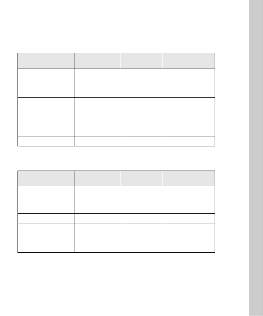
Guide to models and functions
OptraImage multifunction options
Model number Copy function Fax function Scan to network
function
OptraImage 212 X X
OptraImage 222 X X X
OptraImage 312 X X
OptraImage 322 X X X
OptraImage 514 X X
OptraImage 524 X X X
OptraImage 715 X X
OptraImage 725 X X X
OptraImage multifunction solutions
Model number Copy function Fax function Scan to network
function
OptraImage
Color 1200r
OptraImage
Color 1200p
OptraImage W810s X X X
OptraImage W810p X X
OptraImage T612s X X X
OptraImage T612p X X
XX X
X X
3
Page 12
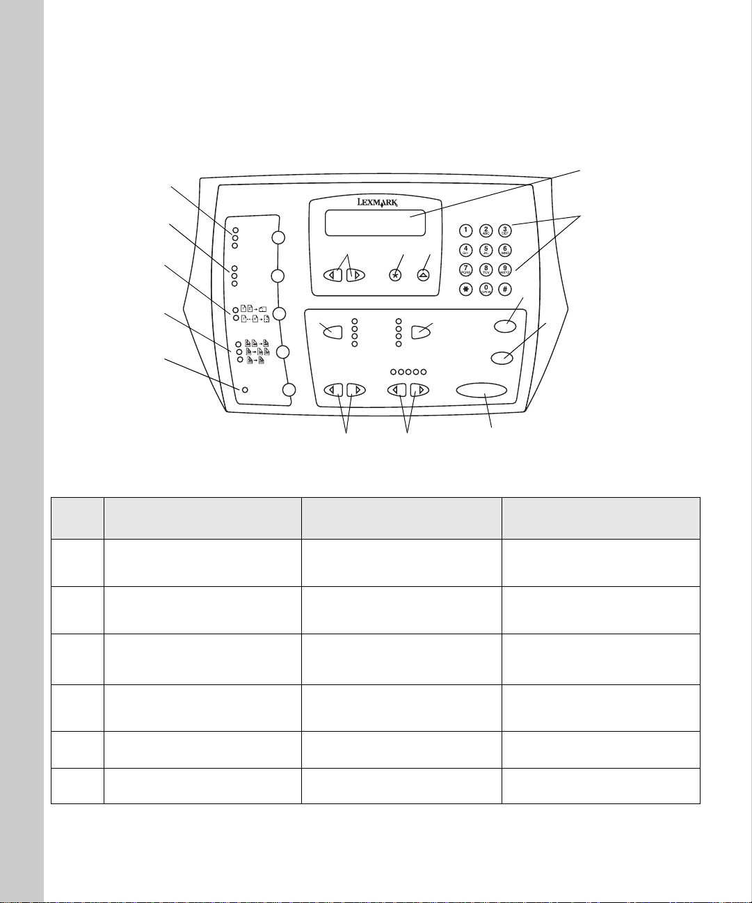
Control panel guide
17
1
2
9
15
14
13
16
3
6
12
4
5
8
7
11
10
Key Function in copy mode Function in fax mode Function in scan to
network mode
1
2 Keypad for entering number of
Control panel status displays for
copying and a
copies to be made.
Ready message
Control panel status displays for
faxing and a prompt to Enter Number.
Keypad for entering out g oi ng fax
phone numbers.
Control panel status displays for
scanning and current scan to
network destination.
Keypad for entering numbers to let
you move around in destinatio n
lists.
3 Menu> and <Menu moves you
forward and backw ard in cop y
menus.
4 Select makes your choice active and
saves your setting.
5 Return takes you back to previous
menu choice.
6 Original Size defines the size of the
original (lette r, legal, A4, ot he r).
Menu> does not apply to fax mode.
Backspace (<Menu) lets you mov e
backward to reent e r information.
Pause lets you insert a two second
dial out pause in a outgoing fax
phone number.
Redial sets the fax modem to redial
the outgoing fax phone number
Original Size defines the size of t he
original (lette r, legal, A4, ot he r).
4
Menu> and <Menu moves you
forward and backward in
destination lists.
Select makes your choice active and
saves your setting.
Return takes you back to previous
menu choice
Original Size defines the size of the
original (letter, legal, A4, other).
Page 13
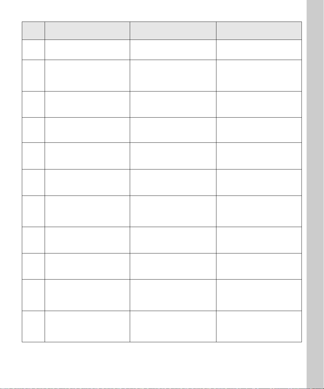
Key Function in copy mode Function in fax mode Function in scan to
network mode
7 Copy Size specifies the size of the
copy (letter, legal, A4, other).
8 Fax/Scan Mode displays a Ready
status message ind ic a t in g y ou are in
copy mode.
This is the control panel d efault
mode.
9 Stop/Clear clears the number of
copies so you can start over or
cancels the copy job being sent.
10 Go/Send starts the process of
11 <Lighter or Darker> adjusts the
scanning an o rigin al and sen ding th e
copy to the printer.
darkness of the copy being made.
For more information, se e “Change
the brightness” on page 37.
12 <Reduce or Enlarge> adjusts the size
of the copy being made.
For more information, se e “Set the
copy size” on page 37.
13 Collation/Finishing collates the
copies being made.
For additional information, see “Set
Collation/Finishing features” on
page 40.
Copy Size does not ap p ly to fax
mode.
Fax/Scan Mode displays an
Number prompt in fax mode.
See “Control panel function modes”
on page 6.
Stop/Clear stops a fax from being
sent or cancels a fax that is already
being sent. Control panel returns to
copy mode.
Go/Send activates the fax dial out
process.
<Lighter or Darker> adjusts the
darkness of the fax being sent.
<Reduce or Enlarge> does not apply
to fax mode.
Collation/Finishing does not apply
to fax mode.
Enter
Copy Size changes the size setting
for the scanned file (letter, legal, A4,
other).
Fax/Scan Mode displays your
custom scan profile name or a list of
e-mail and FTP destinations.
See “Control panel function modes”
on page 6.
Stop/Clear stops the scan job and
returns the control panel to copy
mode.
Scan jobs must be resubmitted.
Go/Send starts the process of
scanning a document and sending it
to a file, as an e-mail, or to a
designated FTP server
<Lighter or Darker> adjusts the
darkness of the copy being made.
See “Change the brightness” on page
37.
<Reduce or Enlarge> does not apply
to scan to network mode.
Collation/Finishing does not apply
to scan to network mode.
14 D uplex specifies the type of duplex
copies being made.
For more information, se e “Set the
duplex option” on page 39.
15 Paper Saver lets you print copies 2-
up or 4-up in order to save paper.
For more information, se e “Save
paper when you print” on page 40.
16 C opy M edia spec ifies the type of
media for your printed copies (plain
paper, transpar enci es, other).
17 Content lets you specify the content
of your original being copied (text,
mixed, photo).
Duplex does not apply to fax mode,
unless you have duplex capabilities
on your scan unit.
Paper Saver does not apply to fax
mode.
Fax Resolution specifies the
resolution of your fax (standard, fine,
super fine, ultra fine).
Standard is the default (no lights).
Content lets you specify the content
of your outgoing fax (text, mixed,
photo).
5
Duplex does not apply to scan to
network mode, unless you have
duplex capabilities on your scan
unit.
Paper Saver specifies the orientati on
(portrait or landscape) of your
original documents (applies only to
PDFs).
Fax Resolution specifies the
resolution and JP EG quality of your
scan to network job (standard, fine,
super fine, ultra fine).
Standard is the default (no lights).
Content lets you specify the content
of the original being scanned (text,
mixed, photo).
See “Custom Scan to PC se ttings” on
page 57.
Page 14
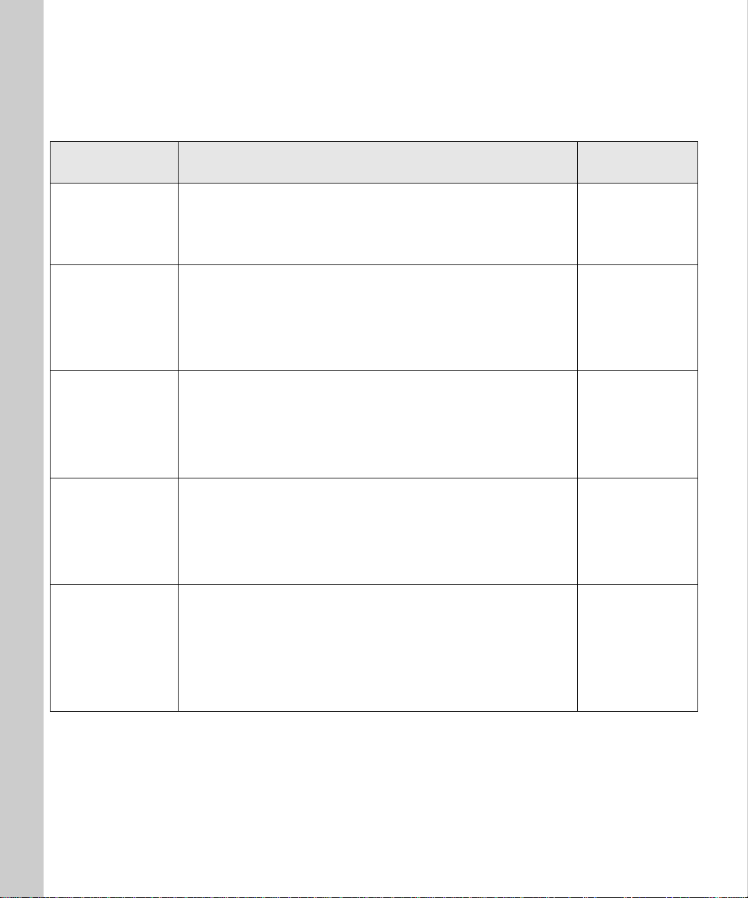
Control panel function modes
Control panel
mode
Copy
Fax
Scan to Profile
(back to PC or to
an e-mail)
Scan to e-mail
(permanent
destinations)
When it appears on the control panel Message
Default mode (you do not need to press Fax/Scan Mode)
In copy mode, you can make a copy simply by placing the document
in the scan unit and pressing Go/Send on the OptraImage control
panel.
If you have a MarkNe t N2501e print server and set the basic fax
information during setup, press Fax/Scan Mod e once to move the
control panel into this mode.
In fax mode, enter the fax phone number of the recipient using the
numeric keypad on the OptraImage control panel, and then press
Go/Send to send the fax.
For your scan profiles to appear on the OptraImage contr ol panel, you
must define your Scan to PC and/or Scan to e-mail job profiles using
the MarkNet resident web server.
In Scan to Profile mode to see your profiles, you must press
Fax/Scan Mode repeatedly until you see
Menu > to advance through your profile names.
For a list of permanent e-mail destinations to appear on the
OptraImage control panel, you must set up each e-mai l recipient
using the MarkNe t res ident web server.
In Scan to e-mail mode to see your e-mail destination list, you must
press Fax/Scan Mode repeatedly until you see
Menu > to advance through your permanent destinations.
Scan → Profile, and then
Scan → e-mail, and then
displayed
Ready
Enter number
→ Profile
Scan
Scan
→ e-mail
Scan to FTP
(FTP servers)
For a list of Scan to FTP servers to appear on the control panel, you
must set up the FTP servers using the MarkNet resident web server.
In Scan to FTP mode to see a list of your configured FTP servers, you
must press Fax/Scan Mode repeatedly until you see
then Menu > to advance through your FTP servers.
Note: You can create multiple FT P servers, but you can only s can to
one server at a time.
Scan → FTP, and
6
Scan
→ FTP
Page 15

Chapter 1:
Setup
Prerequisites - - - - - - - - - - - - - - - - - - - - - - - - - 8
Set up and configure - - - - - - - - - - - - - - - - - - - - - 9
Install the MarkNet print server in the printer - - - - - - - - -9
Attach the co ntrol panel overlays- - - - - - - - - - - - - - - 10
Check control panel and scan unit switch settings - - - - - - 10
Choose a location for the c ontrol panel - - - - - - - - - - - - 11
Remove scan unit shipping retainer or carrier bracket - - - - 12
Install the ADF on your scan unit- - - - - - - - - - - - - - - 14
Attach all the cables- - - - - - - - - - - - - - - - - - - - - - 16
Attach all the power cords and power up - - - - - - - - - - 17
Print a network setup page - - - - - - - - - - - - - - - - - - 18
Set an IP address in the MarkNet pr int server - - - - - - - - 18
Set require d fax informati on - - - - - - - - - - - - - - - - - 20
Configure scan to network functions - - - - - - - - - - - - - 23
Restrict OptraImage usage - - - - - - - - - - - - - - - - - - 28
Verify the set up - - - - - - - - - - - - - - - - - - - - - - - - 30
Solve setup problems - - - - - - - - - - - - - - - - - - - 31
7
Page 16

Prerequisites
Set up your printer
1 Follow the hardware setup instructions in the documentation that shipped
with your printer. This includes setting up all bins and trays, duplex
hardware, and any other options you may have purchased.
2 If you attach your printer to a network during printer setup, save your
network setup page because you will use the information contained on it
during the OptraImage setup.
3 When you have finished, verify the printer hardware setup by printing the
menu settings page. Instructions for printing this page are included in
your printer setup documentation.
IMPORTANT: Turn All Power Off
Before and during the OptraImage setup, all equipment should be turned off.
All power cords, fax/phone cables, and network cables should be unplugged
from their wall outlets. This includes all cords and cables attached to the PC,
printer, MarkNet print server, OptraImage control panel, sca n unit, and any
other peripherals powered from a wall outlet.
Following setup, all equipment may be plugged into properly grounded or
fax/phone wall outlets and turned on.
8
Page 17
Set up and configure
See “Safety Information” on
page v for additional cautions
and warnings.
MarkNet internal print
servers are sometimes called
printer option cards.
1
Install the MarkNet print server in the
printer
❏ If your printer shipped with the MarkNet N2501e or N2401e print server
already installed, or if you installed one of these prin t servers during
your printer setup, skip to the next step.
Caution: Before installing the MarkNet N2501e print server in your printer,
make sure the fax/phone cable is not plugged into the card or the
wall outlet. Make sure your printer is unplugged.
Install the MarkNet N2501e or N2401e pr int server in a n avail able opt ional car d
slot inside your printer. For detailed instructions about installing your print
server, refer to your printer setup documentation abou t installing option cards.
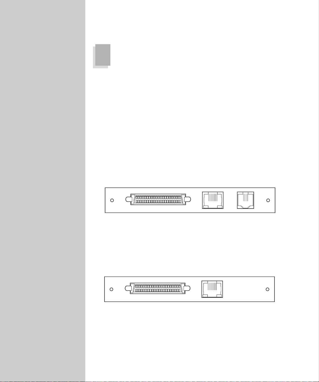
MarkNet N2501e print server ports
SCSI port (OptraImage
control panel attaches
here)
Ethernet 10/100
port (uses RJ-45
cable)
Fax Modem
port (uses RJ-11
cable)
MarkNet N2401e print server ports
SCSI port (OptraImage
control panel attaches
here)
Ethernet 10/100
port (uses RJ-45
cable)
9
Page 18
2
Attach the control panel overlays
❏ If you received a control panel with overlays already applied, skip to
the next step.
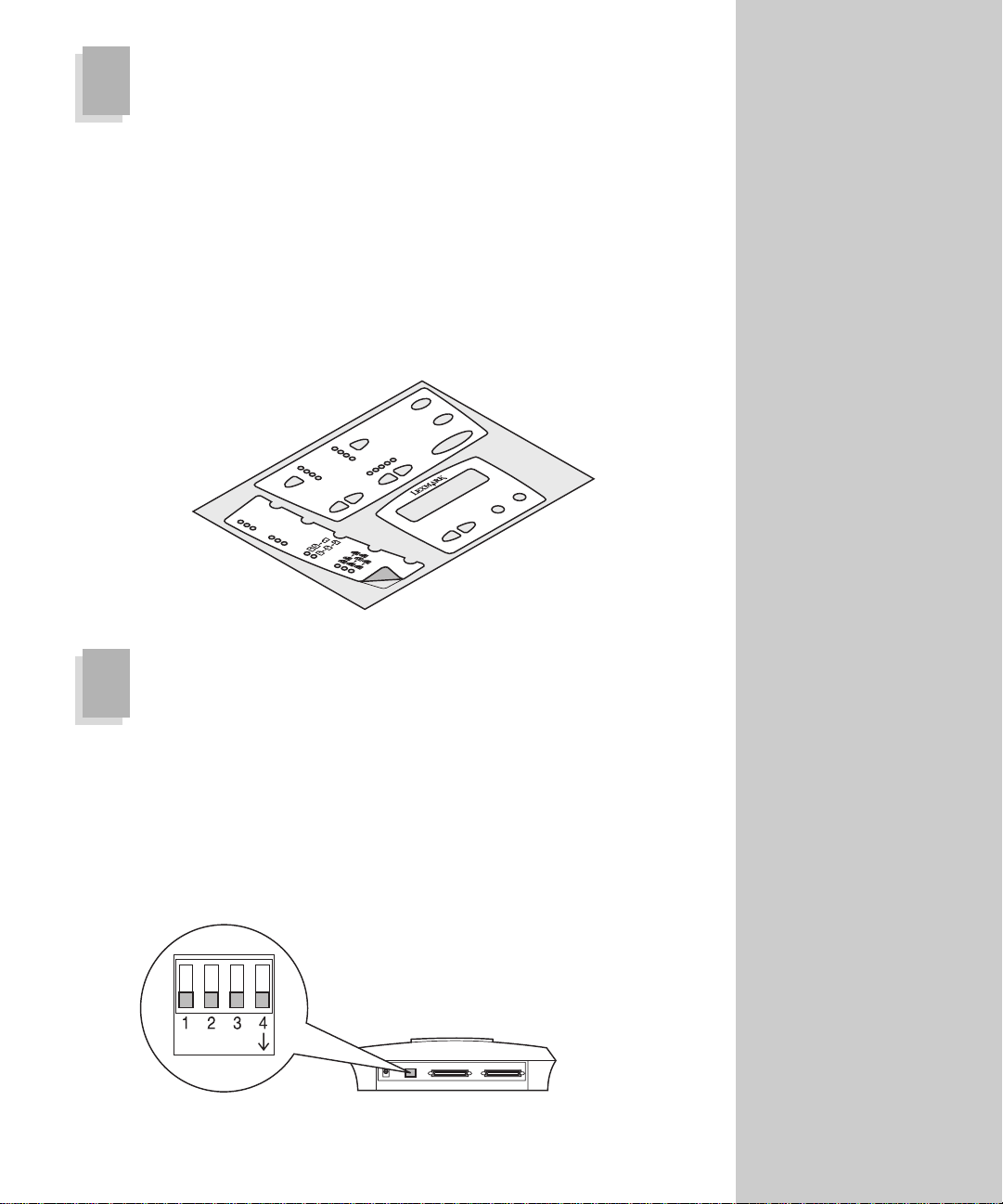
1 Choose the overlays in your language.
2 Peel each section from the backing, and then press it firmly on the
OptraImage control panel.
Important: Because the indicator lights need to shine through the overlay,
carefully align the edges and the holes.
3
Check control panel and scan unit switch settings
Some control panels are
shipped with the English
overlays already attached.
Some are shipped without any
overlays attached.
Control panel switch settings
Before connecting the OptraImage control panel to the other hardware, check
the dip switch settings. Make sure all switches are in the down position (on).
Switch 4 determines the SCSI bus termination setting of the control panel.
10
Page 19
Scan unit SCSI ID and termination settings
If you purchased an
OptraImage 514/524, refer to
the documents that shipped
with your sc an unit for
information about default
switch and termination
settings.
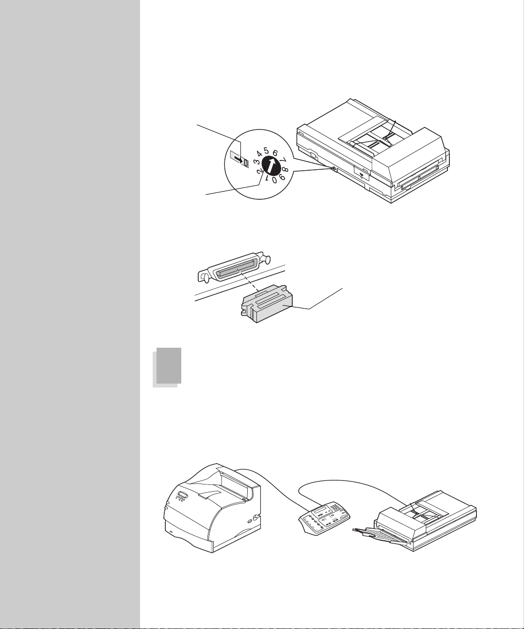
If you purchased an OptraImage 212/222, 312/322, Color 1200r, Color 1200p,
T612s, or T612p, make sure the SCSI ID is set to 6 and the termination switch is
pushed all the way to the right.
Ter mination
switch
SCSI ID
(default is 6)
If you purchased an OptraImage 715 /725, W810s, or W810p, make sure the
terminator is still installed on one the SCSI ports o f th e scan unit.
Terminator
4
Before assembling the system and connecting the cables, choose a good location
for the control panel. Normally, a location near the scan unit works best.
The following illustration is th e recommended OptraImage setup.
Choose a location for the control panel
11
Page 20
5
Remove scan unit shipping retainer or carrier bracket
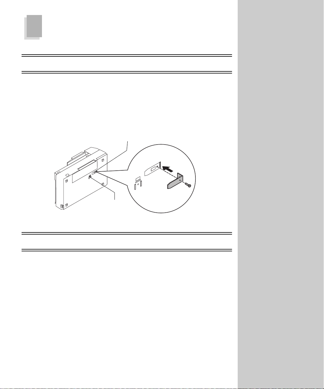
OptraImage 212/222, 312/322, Color 120 0, T6 12
Remove the shipping retainer before using the scan unit.
1 Place the scanner on its side.
2 Remove the retainer screw.
3 Pull out the shipping retainer, and put it in the “use” position.
Use position
Shipping position
OptraImage 514/524
For information about the scan unit you purchased with you r Op traImage
514/524, refer to the documentation that shipped with the scan unit.
Return the shipping retainer
to its original position before
moving the scan unit. For
more information, see
“Moving the scan unit” on
page 83.
12
Page 21
OptraImage 715/725 and W810
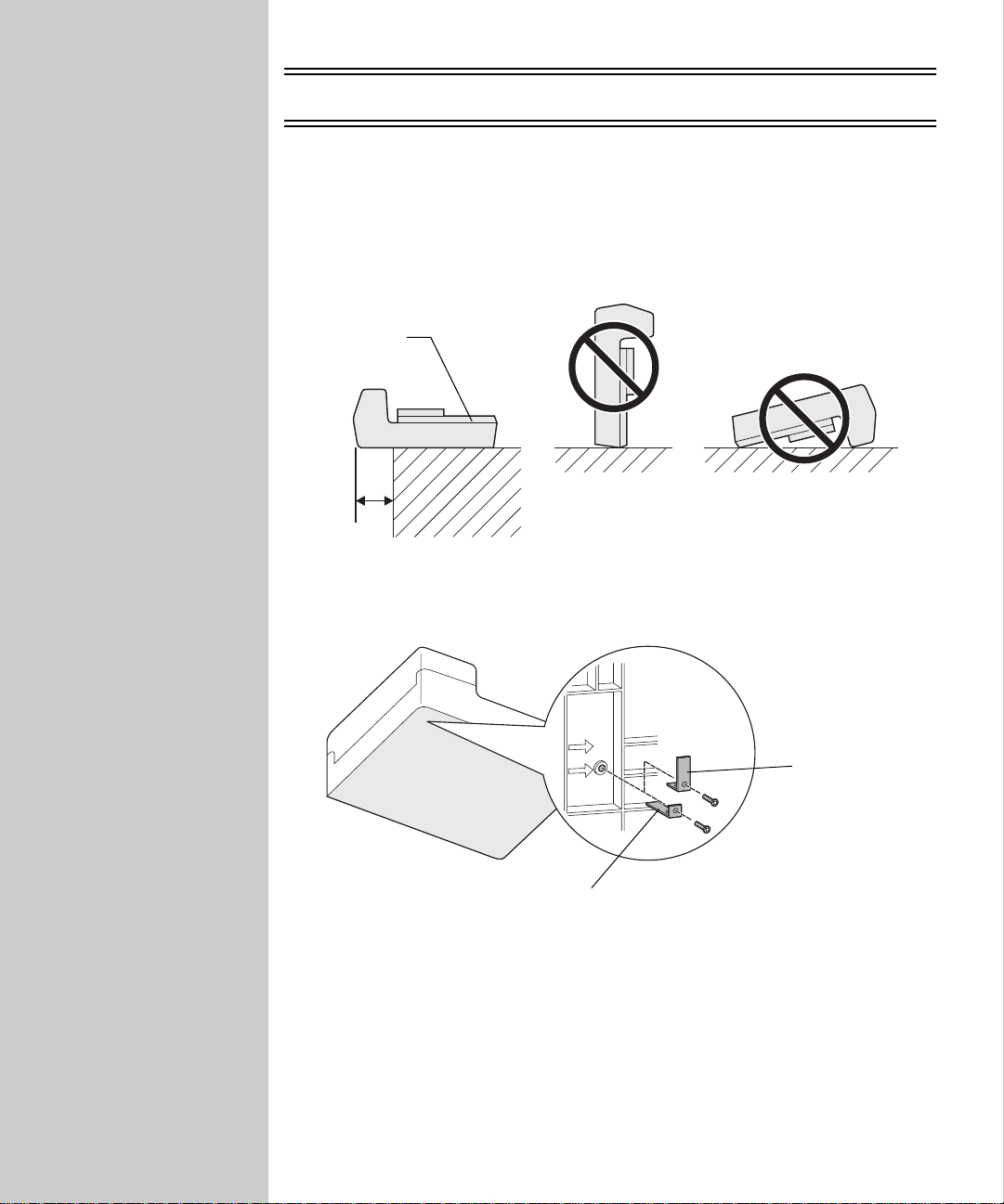
Remove the carrier bracket before using the scan unit.
1 Place the scan unit on the edge of a flat surface with its left side extended
over the edge.
Caution: Do not turn the scan unit upside down or on its side.
Correct
2 Move the carrier bracket from its shipping position to the operation
position.
13
Operation
position
Shipping
position
Page 22
6
Install the ADF on your scan unit
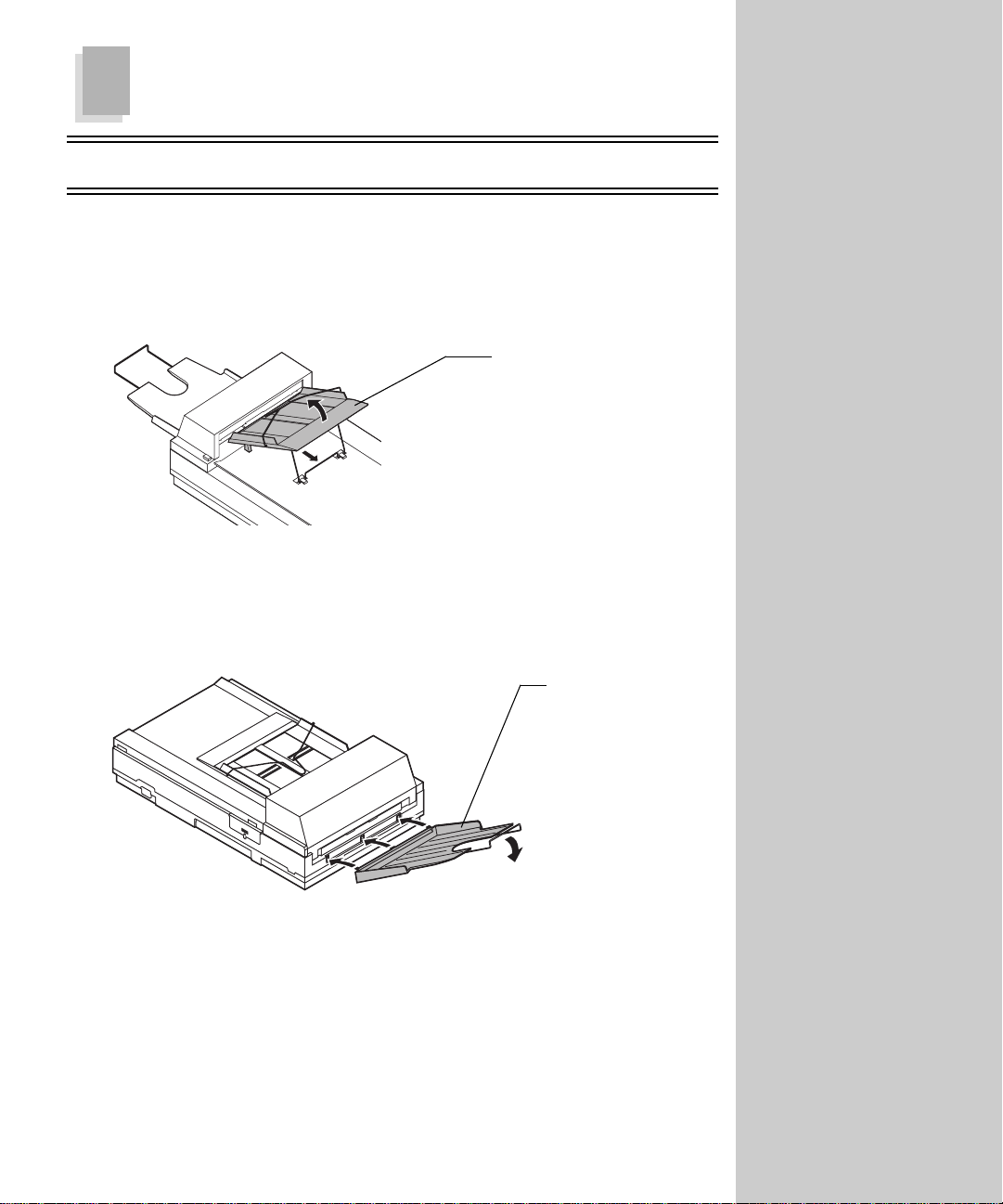
OptraImage 212/222, 312/322, Color 120 0, T6 12
1 Raise the document cover to about 45 degrees.
2 Place the ADF paper chute to about 45 degrees. Insert the ADF paper chute
to auto feeder holes on the document cover as shown.
ADF paper chute
3 Pull out the wire leg under the paper chute and snap it into place.
4 Pull out the paper chute extension to the length you want.
5 Hold the output paper rack to about 30 degrees.
Output paper
rack extension
The ADF is the Automatic
Document Feeder.
6 Insert the three clasp-joints on the output paper rack into the ADF.
7 Release the paper rack gently. Make sure the rack is firmly attached to the
ADF.
8 Pull out the output paper rack extension to the length you want.
14
Page 23
OptraImage 514/524
For information about installing the ADF of your OptraImage 514/524 sc an
unit, refer to the documentation that shipped with the scan unit.
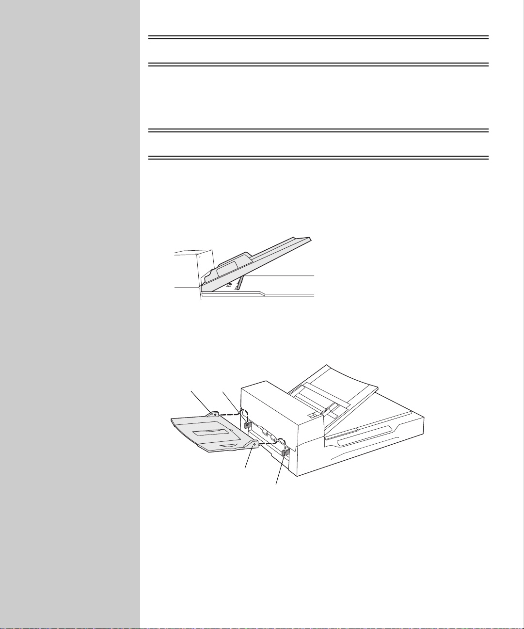
OptraImage 715/725 and W810
1 Raise the ADF and secure it with the metal leg attached.
2 Extend the paper chute enough to accommodate the length of your
originals according to the paper guide settings on the chute.
3 Install the ADF output stacker. Hook the pins in the claws on the scan unit.
Pin
Claw
Pin
Claw
15
Page 24
7
Attach all the cables
Telephone fax line cable
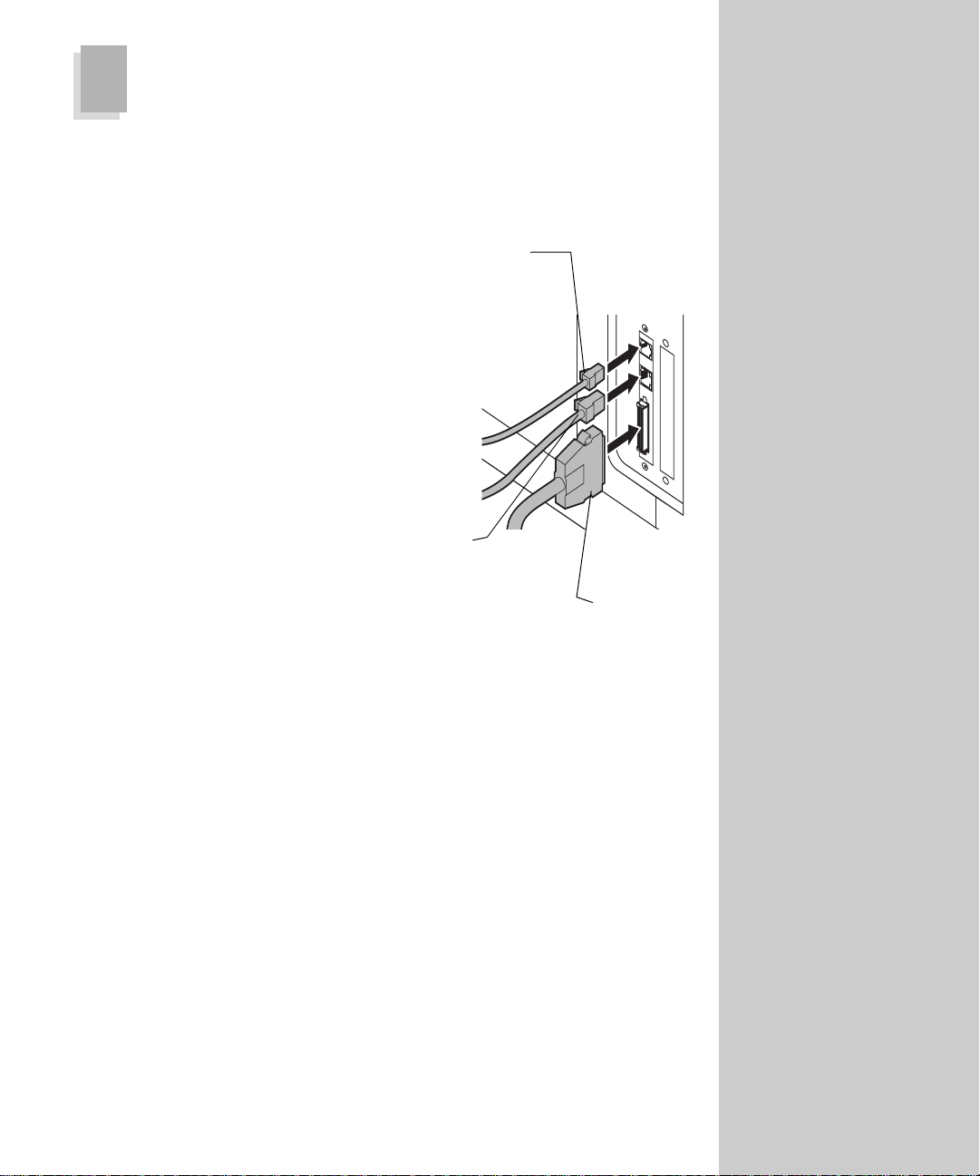
To send or receive faxes, you must
plug the RJ-11 telephone fax line cable
into the fax modem port of the back on
the MarkNet N2501e print server
installed in your printer.
You may have received a telephone
adapter with this product, one
specifically designed for use in your
country. Attach the telephone adapter
to the telephone fax line cable.
However, do not plug the fax telephone
cable into the wall outlet yet.
Network cable
If you want to be able to send network
print jobs to your printer, plug the
Ethernet cable into the Ethernet
network port on the back of the
MarkNet print server installed in your
printer.
Telephone fax
line cable (RJ-11)
Ethernet
network cable
SCSI cable
Use only the German TAE
type F adapter (P/N 14B5123)
shipped with this product
because it contains a billing
tone filter. The adapter is
designed only for the
F connector of the German
wall outlet. This must be the
only device attached to the
NFN wall receptacle.
Use only the Switzerland
adapter (P/N 14B5109)
shipped with this product
because it contains a billing
tone filter.
.
SCSI cables
The SCSI cables connect your scan unit, control panel, and printer to each
other.
Important: Hook up the SCSI cables in this step, but do not connect the
power cords or turn the power on yet. This will be done in the
next step.
16
Page 25
8
Attach all the power cords and power up
Important: The control panel does not have an ON/OFF switch. Be sure to
follow the preferred order of powering on: first the scan unit, and
then the printer.
a Ma ke sure the printer power is turned off and the printer power cord is
unplugged.
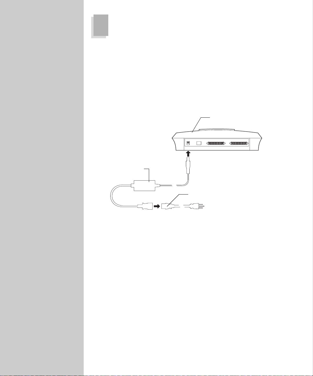
b Using the diagram as a guide, connect the power supply to the control
panel.
OptraImage control panel
Power supply
Power cord
c Connect the power supply to the power cord, but do not plug the
power cord into the wall yet.
d Connect the power supply of the scan unit.
e If you purchased a MarkNet N2501e, plug the telephone fax line cable
into the phone line wall outlet.
f Plug each of the power cords into a properly grounded electrical outlet.
The control panel power comes on automatically.
g Plug the printer power cord back in.
h Turn the scan unit on.
i Turn on the printer.
17
Page 26

9
Print a network setup page
❏ If your printer is not attached to a net work, skip to step 11.
❏ If you completed your network setup during step 1 and already have
your network setup page, skip to step 11.
Use the printer operator panel to print a network setup page (Network Menu/
Network Option x/Network x Setu p/Print/ Print S etup Page ). Save this page because
you will use it in the next step.
10
Set an IP address in the MarkNet print server
❏ If you do not have a TCP/IP environment, skip to the next step and use
the OptraImage control panel method of configuring to set up your fax
function.
Assign an IP address, netmask an d gateway for other network devices to find
the printer on the network.
Networks using DHCP
For more information about
using the printer operator
panel, refer to your printer
documentation.
For instructions about other
ways to set the IP address, look
on the Drivers, MarkVision
and Utilities CD. Click View
Documentation and look for
the MarkNet link.
Some OptraImage functions,
like scanning to your network,
cannot be configured using the
control panel and require that
you use the MarkNet resident
web server.
If you have DHCP, the proper address values are automatically assigned. Look
for the information on your network setup page. Once you find the address, go
to step 11.
Note: Some networks take several minutes to communicate with other
devices on the network. If the network setup page doesn’t contain the
information you think it shou ld , such as an automatically assign ed IP
address, and then wait a few minutes and try printing the page again.
18
Page 27

It doesn’t matter which form of
the UAA you use (MSB or
canonical).
Information on installing,
using and troubleshooting the
utility resides on the CD.
“X” designates which option
card slot in the printer is being
used. For example, if you
install the MarkNet print
server in option slot 2, the
printer operator panel
displays: Network Option 2.
Networks not using DHCP
If you don’t have DHCP, there are other methods you can use to manually
assign address values, such as the printer operator panel, sta tic ARP an d teln et,
RARP and telnet, BOOTP, MarkVision or other Lexmark utility. Two of these
methods follow.
Warning: Manually setting an IP address is a task generally performed by a
network administrator and can affect other network settings. Do not
attempt to manually assign an address unless you are sure it is
appropriate to do so.
Method 1: Print server TCP/IP setup utility
You can use this simple utility to initialize the IP address if your workstation is
running Windows 95, Windows 98, Windows NT, or Windows 2000. You need
to know the 12-digit physical address (UAA) of the print server to use this
method. The UAA is on the network setup page you printed earlier.
To install the utility, launch the Drivers, MarkVision and Utilities CD that
shipped with your hardware, do a custom install to add network support, and
then select Print Server TCP/IP Setup Utility. Follow the in structions on the
screen.
Method 2: Printer operator panel
A simple way to set the IP address inside the MarkNet print server is to use the
printer operator panel. You need to be standing at the printer to use this
method.
1 On the printer operator panel, select Network Menu, Network Option X, Network X
Setup, TCP/IP,
see the menu item, and then press Select.)
2 When the current IP address is displayed (default is zeros), use the buttons
to change the address. (Hint: Pressing Select advances to the next segment in
the address. Pre ssing Menu> increas es the number by one. <Menu decreases the
number by one.)
3 When you finish setting the IP address, press Select repeatedly until the
SAVED appears briefly.
word
4 Print a new network setup page to verify the information was entered as
you intended.
and then Set IP Add ress. (Hint: Press Menu> rep eat edly until you
19
Page 28

11
The Telephone Consumer Protection Act of 1991 makes it unlawful for any
person to use a computer or other electronic device to send any message via a
telephone fax unless the message clearly contains the following information in a
margin at the top or bottom of each transmitted page, or on the first page of the
transmission:
❏ the date and time it is sent
❏ an identification of the business or other entity, or other individual
❏ the telephone number of the sending machine or business, other entity,
Set required fax information
sending the message
or individual
See “Emission Notices” on page 100 and “Telecommunications Notices” on
page 101 for more FCC information.
Two ways to set required fax information
There are two ways to set the required fax information required by the FCC.
❏ MarkNet resident web server (recommended) -- If your printer is
attached to a TCP/IP network, type the IP address in the URL field of
your browser to access the MarkNet resident web server stored on th e
print server and set the required fax information.
❏ OptraImage control panel -- If your printer is not attached to a TC P/IP
network, the required fax information is set using the numeric keypad,
buttons, and menus on the OptraImage control panel. Use this method if
your printer is locally-attached, or if your printer is attached to a
network not running TCP/IP.
The FCC is the Federal
Communications
Commission.
20
Page 29

Use the MarkNet resident web server (IP only)
Configuration is a task usually
performed by a network
administrator or other system
support person. If you are
prompted for a password, see
your support person for help.
During printer power up the
MarkNet print server searches
your network for a Network
Time Protocol (NTP) time
server. If it finds a NTP time
server, and then the current
date and time are provided by
the time server. However, you
must set the country and time
zone to get the correct time.
After the IP address is set (using any method), use your browser to set the
required fax information.
1 Type the IP address of the MarkNet print server in the URL field of your
browser (for example, http://192.168.236.24), and then press Enter.
2 Click Configuration.
3 Under the OptraImage heading, click FAX Set up.
4 Enter the required FCC information:
• Date and Time (change to current date and time)
• Station Name (your personal name or company name)
• Station Number (your fax phone number)
5 Select the Country and Time Zone, such as USA/Can. Ea stern (USA and
Canada, Eastern Standard Time). This sets the required information.
6 Set or change any additional fax settings you want. For detailed
information about these additional settings, see “Chapter 3: Faxing” on
page 45.
7 After entering the information, click Submit.
Create a fax destination list
Instead of entering the entire phone number of a fax recipient on the control
panel each time you want to send a fax, you can create a permanent fax
destination and assign a shortcut. All you need to do to send a fax is press #,
and then enter the assigned shortcut number on the numeric keypad of the
OptraImage control panel.
A list of these shortcuts can be
viewed and printed. See “Print
the shortcut list” on page 60.
1 Click Configuration.
2 Click Manage Destinat io ns.
3 Click FAX Destinations Setup.
4 Enter a unique name for the fax recipient and specify their fax number.
5 Assign a shortcut number (1-89). If you enter a number already in use, you
are prompted to select another number.
6 Click Submit.
21
Page 30

Use the OptraImage control panel
If you have purchased a MarkNet N2501e print server, during power up a
message displays in the control pan e l asking you to
prompt to begin the required fax setup.
Special tips for setting fax information:
• When entering characters or numbers, repeatedly pressing each
number on the numeric keypad changes it from a number , and then to
the uppercase character, and then to the lowercase character , and then
to the next character.
• When entering a specific character or number, pressing Menu> or
<Menu scrolls through all choices. This als o offers you additional
characters not found on the numeric keypad, such as left and right
parenthesis, dashes, quotes, and so on.
• Press the Copy Size
Size button to move to the previous field.
button to move to the next field or the Original
1 On the control panel, press Menu> repeatedly until you see Fax Quick Setup,
and then press
Select.
2 When Country/Zone appears, use Menu> to find your country and time zone
(for example,
US/Can Eastern), and then press Select to save your choice.
3 Set the current date and time:
• If the correct date and time appear on the display, press Return to go
to the next menu item.
• If the default date and time appear (
use the nu meric keyp ad to change the numbers in each field. After the
date and time are set, the next menu item appears.
4 When you see Station Name, enter your name or company name using the
numeric keypad on the panel.
5 Press Return when you have finished entering your Station Name. SAVED
briefly appears.
6 When you see Station Number, enter yo ur fax ph one number using the
numeric keypad on the panel.
7 Press Return after entering your Station Number. SAVED briefly appears.
After the last menu item has been entered, Setup Comp lete appears.
For additional help in understanding the control panel, see the “Control panel
guide” on page 4.
Please Set Time. This is the
1900-01-01 15:35) on the display,
22
Page 31

For more information, see
“Control panel guide” on page
4 and “Control panel function
modes” on page 6.
12
❏ If you do not want to add scan to network functions, skip to the next
In addition to making copies and se nd ing faxes, OptraImage lets you scan
documents and send them to destinations on your network.
There are three scan to network modes:
For the control panel to display menus for
Scan → FTP, you must configure each of these scan to network modes using the
MarkNet resident web server.
Configure scan to network functio ns
step.
• Scan to Profile (for single use scan jobs)
• Scan to e-mail (to a permanent destination)
• Scan to FTP (to an FTP server)
Scan → Profile, Scan → e-mail, or
Scan to network general setup
Configure default scan job settings
After you create a list of
permanent destinations, it
becomes available in the
OptraImage control panel,
these default settings are
active choices for your typical
scan job.
You can configure some default scan job settings th at preset the OptraImage
control panel formats for all Scan to e- mail and Scan to FTP jobs.
1 Browse to the MarkNet resident web server.
2 Click Configuration.
3 Under the OptraImage heading, click Scan to Network General Setup.
4 Set your default scan job settings. Base these settings on the most common
types of originals you will be scanning . H owever, these are just defaults
and can be overridden by changing the control panel before you begin
scanning.
5 Click Submit.
23
Page 32

Limit the available scan to network functions
You can limit the scan to netwo rk fun c tions available on a particular
OptraImage control panel. You can disable one, two, or all three functions.
• Disabling Scan to Profile prevents anyone from creating a profile, plus the
function is not visible in the OptraImage control panel.
• Disabling Scan to e-mail or Scan to FTP lets you create or add permanent
destinations but the mode is not visible in the control panel so the scan job
cannot be sent.
• Disabling the multipage TIFF function places each page of a scan job in a
individual TIFF file rather than placing all pages in a single, multipage
TIFF file.
1 Browse to the MarkNet resident web server.
2 Click Configuration.
3 Under the OptraImage heading, click Scan to Ne twork General Setup.
4 Remove the check mark from any function you want to disable. You can
disable any scan to network mode without affecting the others. You can
also disable the ability to scan to a multi- page TIFF file.
5 Click Submit.
Configure Scan to E-mail
Specify SMTP gateway and other E-mail settings
In addition to identifying your SMTP gateway, you can also enter a generic
subject and message that will be included on all Scan to e-mail jobs.
1 Browse to the MarkNet resident web server.
2 Click Configuration.
3 Under the OptraImage heading, click Scan to E-mail General Setup.
4 Specify the SMTP gateway of your network or internet service provider,
plus your e-mail address for the reply line of the message.
5 Enter a subject (descriptive name) and a generic message suitable for use
on all Scan to e-mail jobs. This information appears on all jo bs scanned to
permanent e-mail destinations.
6 To store scanned documents on a Web site and send only a web link in the
e-mail, complete the Web Link section.
7 After entering your choices, click Submit.
24
Page 33

Before you create a
destination, check the list at
the bottom of the Web page.
Make sure your recipient is
not already listed.
You can rapidly find your
e-mail recipient by pressing #
and entering the shortcut
number on the OptraImage
control panel.
Create permanent E-mail destinations
When creating an e-mail destination, decide what kind of e-mail the recipient
will receive. You can send a document scanned to e-mail as an:
• Attachment -- a copy of the scanned document is sent attached to the
e-mail message to the recipient
• Web Link -- the scanned document is sent to a storage area on a Web site
and a only a Web Link to that site is sent to the e-mail recipient
Create a separate recipient entry for each e-mail type and give them unique
names easily identified in the e-mail destinations list.
1 Click Configuration.
2 Click Manage Destinat io ns.
3 Click E-mail Destinatio ns Setup.
4 Enter a unique name for the e-mail recipient and specify the e-mail
address.
5 Select which type of Scan to e-mail you want to send. Attachment is the
most common choice, but you can avoid sending large scanned images as
e-mail if you use a Web Link.
Here is an example of one recipient with two unique names:
Na me Ad dr es s Ty pe Sh or tc ut #
---------------------------- -------- ----------------------------------- ------------------- --------------Smith, Jane smith@m a ilgw.anywhere.com Attachment 5
Smith, Jane2 [email protected] Web Link 6
6 Enter a shortcut number (1-89) to identify the recipient (optional).
7 Click Add/Modify to add the name to the available list of e-mail addresses.
This new recipient is now visible in the e-mail destination list (and the
entry is also available for selection from the OptraImage control panel
menu).
25
Page 34

Configure Scan to FTP
Create FTP server destinations
You can configure Scan to FTP and create a permanent list of FTP destinations.
Afterward, you can take your original documents to the OptraImage and use
the control panel to scan a job to one of these FTP server destinations.
Note: Although you can create multiple FTP server destinations, a scan job
can only be sent to one destination at a time.
1 Browse to the MarkNet resident web server.
2 Click Configuration.
3 Click Manage Destinat io ns.
4 Click FTP Destinations Setup.
5 Assign a name to the FTP server destinat ion. This is the name that will
appear in the OptraImage control panel.
6 Find the address you want to modify in the FTP destination list, and then
click on the name of the recipient. This displays the current address
information in the setup dialog boxes.
7 Make any necessary changes, and then click Add/Modify to update the
address information.
8 After entering your choices, click Submit.
You can rapidly find your
FTP destination by pressing #
and entering the Shortcut
number on the OptraImage
control panel.
Specify an external destinations file
Instead of creating individual e-mail, FTP, or fax destinations one at a time, you
can create multiple destinations and store them in an external ASCII text file.
The ability to specify an external file lets you store a large list of addresses in a
good location on your network, rather than storing them as permanent
destinations in the OptraImage hardware.
The external list is refreshed every 24 hours or during power up.
26
Page 35

Create an external file
A file of permanent destinations (e- ma il and FTP) can be created manually in
any text editor using the following entries as guides:
Type=1 entries are e-mail
Attachments. Type=2 are set
up to be Web Links. Short=0
means no shortcut number has
been assigned.
% Permanent Destinations List F rom 192.168. 236.24
DESTEMAILADD 1 "NAME=Smith, Jane;[email protected]. com;TYPE=1;S HORT=1;"
DESTEMAILADD 1 "NAME=Robb;[email protected];TYPE=1;SHORT=50;"
DESTEMAILADD 1 "NAME=Doe, John;[email protected];TYPE=1;SHORT=0;"
DESTEMAILADD 1 "NAME=Doe, John2;[email protected];T YPE=2;SHORT=0; ”
DESTFTPADD 1
“NAME=smith;SERVER=smith.com;LOGI N=bob;PAS S1=sno; PAS S2=sno; FN=scan; SHORT=20 ;”
DESTFAXADD 1 “NAME=Sheila;NUMBER=5544;SHORT=88;”
This file can be saved with any name and stored anywhere on the network to be
accessed whenever necessary.
Specify the external file
1
Click Configuration.
2 Click Manage Destinat io ns.
3 Click Specify External Destinations File.
4 Specify the server where the file is being stored, plus the login and
password necessary to gain access to the server. Specify the full path and
filename of the file.
5 Click Submit. The file is accessed from the server location. The e-mail and
FTP destinations stored in the external file are added to the current list of
permanent destinations.
6 Check that the process worked by clicking Back on the Browser menu until
you see one of the destinations setup links, such as E-mail Destinations
Setup.
7 Click E-mail Destinatio ns Setup. The e-mail destinations stored in the file
now appear in the e-mail destinatio n list. Yo u may have to scroll through
the list to find them.
Note: The process works the same for FTP and fax entries.
27
Page 36

13
Restrict OptraImage usage
❏ Setting these restrictions require OptraImage users to enter an account
number before they can scan a document. If you don’t want to restrict
usage, skip to the next step.
OptraImage Job Accounting can require OptraImage users to enter a Job
Account number in the control panel or choose a valid Job Account name from
a list before they scan documents.
There are two necessary parts of this configuration:
• Job Accounts need to be created for each authorized OptraImage user.
• Each user must be notified to enter the assigned Job Account number on
the control panel in order to scan.
Create or add a Job Account
1
Browse to the MarkNet resident web server.
2 Click Configuration.
3 Click OptraImage Job Ac c ounting.
4 Click Manage Job Accounts.
5 Enter a name for the Job Account and assign an account number.
6 Click Add/Modify. The new Job Account appears in the list.
Restrict ions can be configured
later using the information
contained in this step.
Protect the Job Account list
To prevent the Job Account list from being modified by unauthorized
individuals, set a password to protect the information stored on the print
server.
1 Browse to the MarkNet resident web server.
2 Click Configuration.
3 Under the Other heading, click Security.
4 Type a password. You must type it a second time for verification.
5 Click Submit.
28
Page 37

Require all scan jobs to be validated
The highest level of security for the OptraImage control panel requires a valid
Job Account number to be entered. This account number is checked against the
master Job Account list before the OptraImage control panel accepts a scan job.
1 Browse to the MarkNet resident web server.
2 Click Configuration.
3 Click OptraImage Job Accounting.
The default mode is Off. 4 Select Validation as the Job Accounting mode.
5 Specify a timeout. The timeout is the amount of time that passes after a
scan job is complete before the control panel is relocked.
6 Click Submit.
After the Validation mode has taken affect, the OptraImage control panel
displays an
To unlock the control panel, a user must enter a valid account number using the
keypad on the control panel, and then press Select.
Enter Account # prompt.
Use a Courtesy tracking mode to restrict usage
There are other Job Accounting modes used primarily for tracking OptraImage
usage, which may be used to minimize the restrictions placed on authorized
users.
To use one of these modes for this purpose, see “Select a Courtesy tracking
mode” on page 75.
29
Page 38

14
Verify the setup
Make a test copy
Copy mode is the default setting of the control panel.
1 Make sure the Ready status message is displayed.
2 Place your original in the scan unit.
3 Press Go/Send to send a copy to your printer.
See “Solve setup problems” on page 31 if the printer does not print a copy.
Send a test fax
Send a one page test fax to someone and ask for feedback.
1 Press Fax/Scan Mode repeatedly until the Enter Number prompt appears.
2 Use the numeric keypad on the control panel and enter the phone number
of the person receiving the fax.
3 Place your original in the scan unit.
4 Press Go/Send to send a fax.
Press Stop/Clear to stop a fax
from being sent or cancel a fax
that is already being sent. The
control panel resets to copy
mode.
Test your scan functions
Test your scan to network functions by creating Scan Profiles or scanning to
permanent destinations. Detailed instructio ns for using the scan to network
functions c an be found in “Chapter 4: Network Scanning” on page 53.
Important: You can only test the scan to network functions that you added
during setup. For example, to test Scan to e-mail function, you must
have created at least one permanent e-mail destination. Otherwise,
Scan → e-mail does not appear as a scan to network mode in the
OptraImage control panel.
30
Page 39
If your problem is not in the
table, see the documentation
that shippe d w it h yo u r pri n te r.
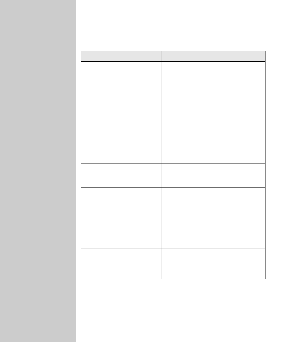
Solve setup problems
Problem Solution
Ready is not displayed on the
control panel display.
The control panel and the printer are not
talking to each o ther, or the printer may be
turned off.
• Turn printer off, and then back on.
• Turn printer and scan unit off. Check that
everything is correctly connected, and
then power up in the correct order. First
turn on the scan unit, and then the prin ter.
A copy of my test document did
not print.
The control panel does not r espond
to any button presses.
I can’t move to next selection when
setting time and date.
The scan unit isn’t working. Turn printer and scan unit off. Check that
I am unable to send or receive
faxes.
• Verify each electrical outlet has power.
• Make sure all cables and line cords are
properly seated.
Make sure the printer is turned on.
Press Copy Size to move to the next selection,
or Original Size to go back. Press Return when
completed.
everything is correctly connected, and then
power up in the correct order. First turn on the
scan unit, and then the printer.
• Ch eck hardware set up. Make sure th e
telephone fax line cable is properly
connected to the fax modem port on the
MarkNet N2501e and to the fax phone
wall outlet.
• The required information may not be set
correctly. Repeat the fax setup. See “Set
required fax inform at ion ” on page 20.
• For more troubleshooting information
about sending or receiving faxes, see
“Solve fax problems” on page 50.
Scan → Profile, Scan → e -mail, and/or
→ FTP doesn’t appear in the
Scan
control panel as modes.
31
Scan to network modes must be configured in
order to show up in the OptraImage control
panel.
See “Configure scan to network functions” on
page 23.
Page 40

32
Page 41

Chapter 2:
Copying
Make copies - - - - - - - - - - - - - - - - - - - - - - - - 34
Simple copies - - - - - - - - - - - - - - - - - - - - - - - - - 34
Examples of typical jobs - - - - - - - - - - - - - - - - - - - 34
Job 1: single copy - - - - - - - - - - - - - - - - - - - - - 34
Job 2: mixed content - - - - - - - - - - - - - - - - - - - - 35
Job 3: use 2-up to save paper - - - - - - - - - - - - - - - 35
Job 4: duplex copies - - - - - - - - - - - - - - - - - - - - 35
Job 5: enlarg e copies - - - - - - - - - - - - - - - - - - - - 36
Job 6: document with color - - - - - - - - - - - - - - - - 36
Adjust copy settings - - - - - - - - - - - - - - - - - - - - 37
Solve copy problems- - - - - - - - - - - - - - - - - - - - 43
33
Page 42

Make copies
Simple copies
1 Make sure you are in copy mode and the Ready status message is
displayed. If necessary, press
2 Place your originals in the ADF of the scan unit, or use the flatbed of the
scanner if you want.
3 Enter the number of copies you want to make using the numeric keypad.
4 Press Go/Send on the control panel to send the copies to your printer.
Note: If you are using the flatbed of the scan unit, watch the control panel
for messages. When prompted to Place next o r stop , press Go/Send to
scan multiple pages or press Stop/Clear to end the scan job.
For additional help in understanding the control panel, see the “Control panel
guide” on page 4.
Examples of typical jobs
Stop/Clear to cancel al l ot her jobs.
The following examples explain how to change the settings on the control panel
to perform specific copying jobs. Each of the examples assumes the necessary
features (duplex, color, and so on) are installed on the scan unit and printer.
Make sure you are in copy mode and the
necessary, press Stop/Clear to cancel all other jobs and reset the control panel.
Ready status message is displayed. If
Job 1: single copy
Make a single copy of a letter-size document.
1 Place your original in the scan unit.
2 Check to see that the display shows 1 as the copy count. If it does not, press
Reset to restore the count to one.
3 Press Go/Send.
34
Page 43

If your scan unit and printer
support duplex, you could also
choose Duplex to save paper.
Job 2: mixed content
Make three copies of a two-page, letter-size document containing one drawing
within the text.
1 Place your originals in the scan unit.
2 Press Collation/Finishing until you see Collate displayed in the control
panel.
3 Press Content until the mixed light comes on.
4 Press 3 on the keypad, and then press Go/Send.
Job 3: use 2-up to save paper
Make eight copies of a four-page document which has some text in color, but
minimize paper usage.
1 Place your originals in the scan unit.
2 Press 8 on the keypad.
3 Press Paper Saver until the 2-up light comes on .
4 Press Collation/Finishing until you see Collate displayed in the control
panel.
5 Press Content until the mixed light comes on, and then press Go/Send.
Job 4: duplex copies
Make a legal-size, two-page document fit on a duplexed, letter-size page for
insertion in a standard-size notebook. The origina ls contain several color
photographs as well as some text.
1 Place your originals in the scan unit.
2 Press Content until the mixed light is on.
3 Press Duplex until the light is on.
4 Press Original Size until the legal light is on.
5 Press Copy Size until the letter light is on.
6 Press Go/Send.
35
Page 44

Job 5: enlarge copies
Enlarge a black-and-white drawing so you can s e e it better and make
annotations.
1 Place your original in the scan unit.
2 Press Enlarge. Hold down the button to rapidly increase the scaling factor.
3 Release the button when 125% appears o n t he display.
4 Press Go/Send.
Job 6: document with color
Make copies of a one page letter-size document containing several small, color
photographs.
1 Place an original page which has a photograph on it in the scan unit.
2 Press Content until the photo light is on, and then press Go to print a copy.
3 Press Content until the mixed light comes on, and then press Go to print a
second copy.
4 Compare the two copies to the original, and then decide which setting
produces the best quality of the photograph. Reset Content to the best
choice (
photo or mixed).
5 Enter the number of copies you want using the numeric keypad.
6 Return the page with the photograph to the scan unit, and then press Go/
Send.
If the scaling factor goes
beyond 125%, use the Reduce
and Enlarge buttons to change
the scaling factor.
Experiment with the Reduce
and Enlarge buttons to get the
copy just the way you want it.
Photo mode is intended to be
used to copy actual
photographs or similar high
quality images.
Photos printed on a printer
should be copied using mixed
mode.
36
Page 45
Adjust copy settings
Change the brightness
Feature Description
Lighter
Darker Produces darker copies.
Produces lighter copies.
Set the copy size
Feature Description
Original Size --
Letter, Legal, A4
Original Size --
Other
T o scr oll to dif ferent paper sizes for the origin al. The paper size
is shown on the display and the indicator light.
• The Other light comes on for paper sizes other than letter ,
legal, and A4. Scroll through the choices and make your
selection.
• If your scan unit supports 11 x 17 or A3 size paper, you can
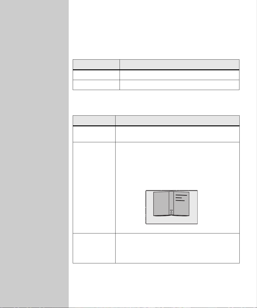
copy a book by pressing Original Size until Book Original
appears in the control panel display.
Place an open book in the scan unit as il lustr at ed. Y o u ca n
copy both pages without repositioning the book.
Copy Size • This selects the size of the copy be ing made from the
available paper sizes in the printer.
• If a particular paper size has not been properly loaded into
the printer, no indication appears on the display for that
paper size.
37
Page 46
Reduce or enlarge
Feature Description
Reduce
To decrease the scaling factor by 1%, press once. Hold this
button down to rapidly decrease the scaling factor.
• If either Reduce or Enlarge is pressed, the Original Size
light is turned off.
• Automa tic scaling between the original and the copy is
used if the paper size selections have been set.
Enlarge To increment the scaling factor by 1%, press once. Hold this
button down to rapidly increase the scaling factor.
• If either Reduce or Enlarge is pressed, the Original Size
light is turned off.
• Automa tic scaling between the original and the copy is
used if the paper size selections have been set.
Select the content
Content defines what kind of original is being copied. The current selection is
indicated by one of the three content lights being on.
Feature Description
text
Select this if the original is composed entirely of text, simple
line-art graphics, or a comb ina t ion of b oth . This choice is the
default.
The highest possible speed is used. Copies are black and
white only, even if the original is color.
One of the content features is
always selected.
mixed Select this if your original has a mix of both text and
graphics.
If both the scan unit and printer are color-capable, this
feature can produce color copies.
photo Select this if your original contai ns extr emely fi ne details and
graphics (actual photographs or similar high quality
images).
If both the scan unit and printer are color-capable, this
feature produces color copies. The h igh est r es oluti on is us ed.
38
Page 47
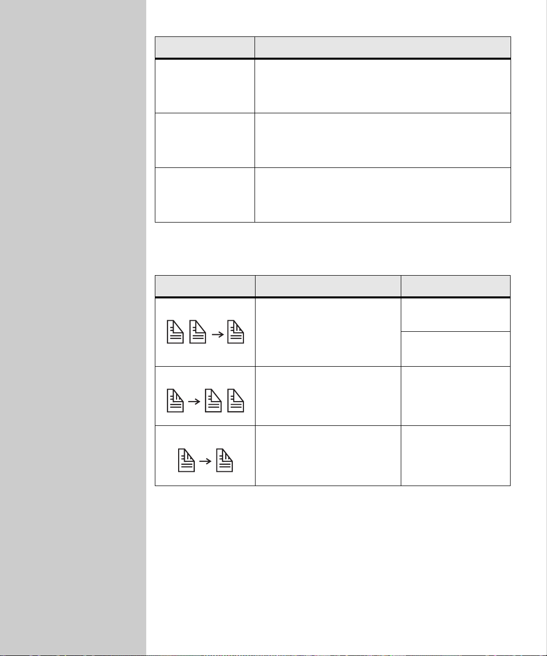
Feature Description
mixed mono
(only available wit h
color scanner/color
printer combinations)
mixed image
(only available wit h
color scanners)
photo mono
(only available wit h
color scanner/color
printer combinations)
Select if the origin al c ontai ns a mi x of b oth text and graphi cs.
Copies are black-and-white only, even if the original is color.
Select if your original has a mix of both text and graphi cs,
but image quality is the highest priority.
If both the scan unit and printer are color-capable, this
featur e can produc e co lor copies.
Select if your original is an a ctual phot ograph or simila r high
quality image.
Copies are black and white only, even if the original is color.
The highest resolution is used.
Set the duplex option
Duplex option Description Display message
Two single-sided originals are
copied to one two-sided copy
(long edge or short edge).
1 > 2
1 > 2 short edge
One double-sided original is
copied to two single-sided
copies.
A double-sided original is co pied
to a double-sided copy.
2 > 1
(available only if scan
unit supports duplex)
2 > 2
(available only if scan
unit supports duplex)
Note: If you press Duplex and no duplex lights come on, no duplex functions
can be performed. This response is normally caused by the scan unit or
printer not having duplex capabilities.
39
Page 48
Set Collation/Finishing features
Collation is turned off by default. To turn Collation on, press
Collation/Finishing until you see
Collate in the control panel display, and then
press Select.
Finishing features (such as stapling or hole punch) are only available if your
printer supports finishing functions. If your prin ter does not support finishing,
and then only collation is supported on the control panel.
Save paper when you print
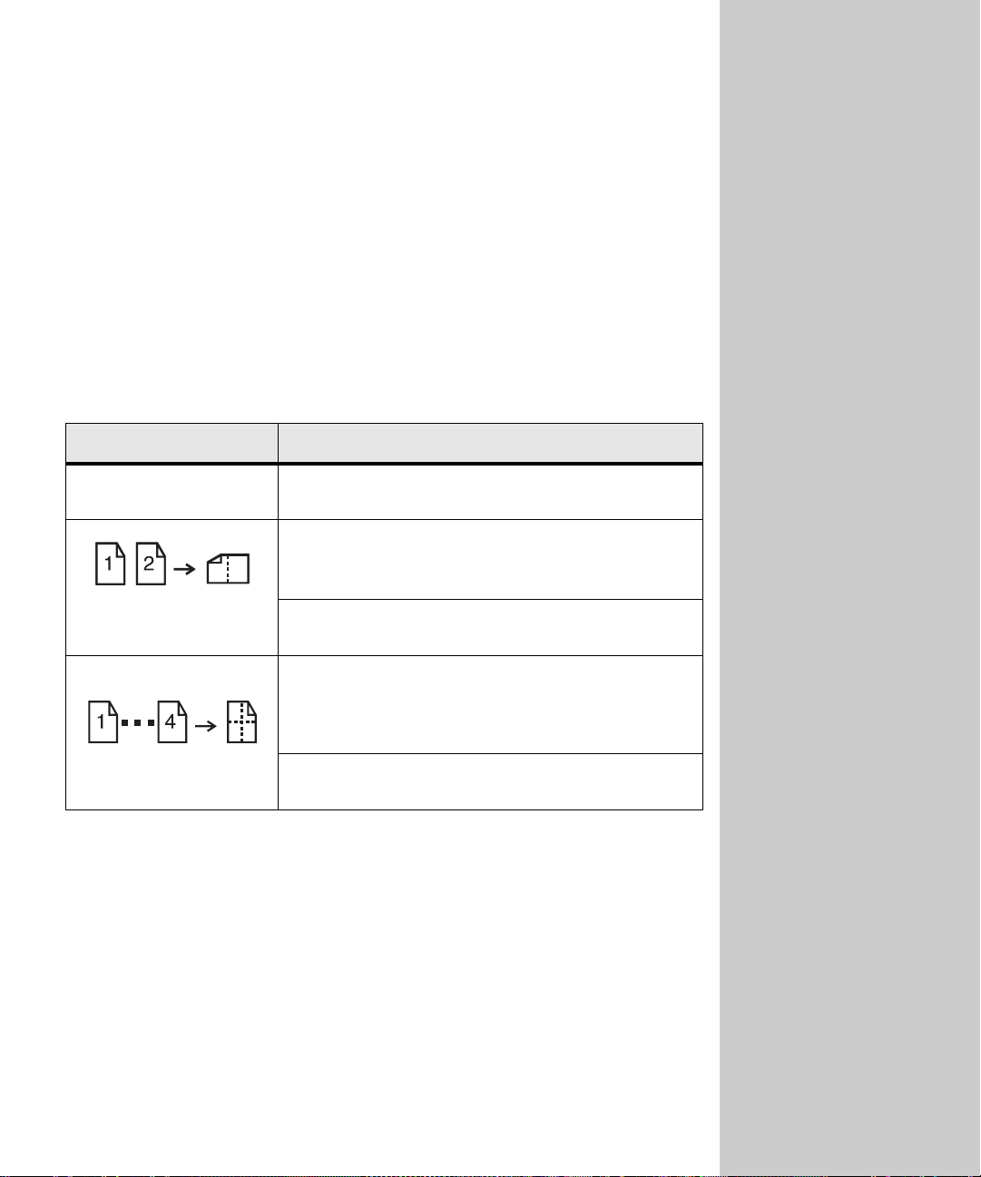
There are five choices available in the Paper Saver menu. Press the Paper Saver
button until your selection appears in the control panel display.
Feature Description
copying is turned off (no choices lit). This is the
Off
N-up
default setting.
2-up copying transfers two originals to one copy.
The two originals are rotated and reduced in size to fit
onto a single sheet, as shown.
2-up Landscape reduces your two originals to fit on a
single sheet of paper in landscape mode.
4-up copying saves even more paper by transferring
four originals to one single-sided copy.
Y our four originals are reduced to fit on a single sheet of
paper in portrait mode.
Turning collation ON
produces complete, ordered
copies of the original.
This process of saving paper is
sometimes referred to as N-up.
Some features share a panel
light. For example, the same
panel light is on for both 4-up
and 4-up Landscape printing.
4-up Landscape reduces your four originals to fit on a
single sheet of paper in landscape mode.
40
Page 49
Select your copy media
The printer may be capable of
using media types other than
plain paper for your copies.
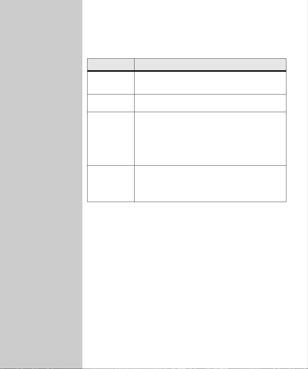
Media type describes the kind of material being printed on, such as plain paper,
transparencies, card stock, and bond paper.
Feature Description
Plain paper
Transparency Choose transparency to draw media from the tray in the printer
Transparency
+Separators
Other T o select fr om other possible copy media. By repea tedly pressing
If plain paper has been loaded properly into the printer, it is
used as the copy media when this light is turned on. Plain paper
is the default for copy media type.
which has been loaded with transparencies.
Press the Copy Media button until the transparency light is lit,
and then press it again until
control panel display.
This feature inserts a plain sheet of paper between
transparencies. For this to work, you must load the
transparencies and paper correctly . The Plain Paper sour ce must
be an automatic tray and the size must be set to be the same size
as the loaded transparencies.
the button, each choice is shown on the display.
Only properly loaded media types are presented as choices.
Refer to your printer documentation for help in loading paper
properly.
Transparency+Sep appears on the
Customize your favorite copy settings
To save time by not having to reenter several button presses, you can customize
your control panel default settings for making copies.
1 Set Content, Duplex and all the other settings the way you typically do.
2 Press Menu > until Copy Menu appears, and then press Select.
3 Press Menu > until Save S etti ngs appears, and then press Select.
4 Press Menu > until =Save appears, and then press Select.
Saving Setting s appears briefly on the display to confirm that the settings have
been entered correctly.
The normal display showing Ready, scaling percentage and number of copies
reappears.
41
Page 50

Restore the factory default copy settings
1 Press Menu > until Copy Menu appears, and then press Select.
2 Press Menu > until you see Factory Defaults displayed, and then press Select.
3 Press Menu > until you see =Restore, and then press Select.
Restoring Factory Defaults appears briefly on the disp lay to confirm that the
settings have been entered correctly.
The control panel displays the Ready status, scaling percentage and number of
copies.
42
Page 51
If your problem is not in the
table, see the documentation
that shippe d w it h yo u r pri n te r.
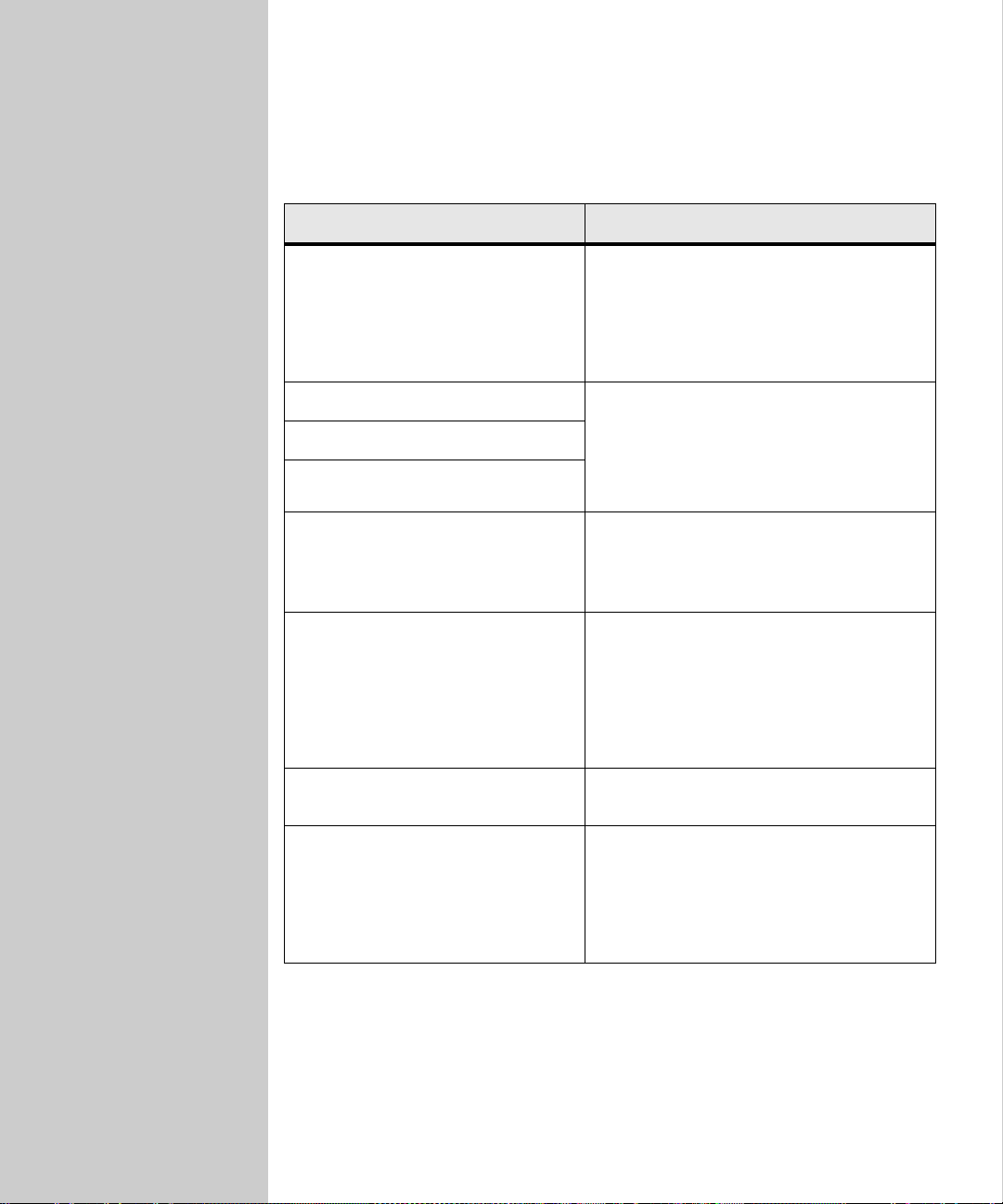
Solve copy problems
Problem Solution
Copy of a color page came out black
and white.
Duplex does not work.
Duplex lights don’t come on.
Can’t select duplex settings.
Ready is not displayed on the c ontrol
panel.
Copy came out on the wrong kind of
paper.
Control panel does not respond to
button presses.
This happens if the scan unit or printer (or
both) can only produce black and white.
If this is not the problem, look in the upper
left corner of the control panel and make
sure Content is set to
and try again.
This usually means the scan unit or printer
(or both) is not capable of duplex.
The control panel and the printer are not
talking to each other or the printer may be
turned off.
Try turning the printer off and back on.
The wrong type of paper is loaded in the
tray containing the copy media you selec ted,
or the printer may not be set up for
automatically selecting the paper type.
Put your special media in the t ra y, check the
paper type setting on the paper menu of the
printer and try again.
The printer is turned off. Turn the printer
back on.
mixed or photo (not text),
Original Size light goes off when
either “Scaling” button is pressed.
43
This action is correct. Setting the Original
Size is done to conveniently select a scaling
factor.
If this setting is overridden by ma nually
setting a scaling factor, the size of the
original is no longer pertinent.
Page 52

Problem Solution
Warning displays on printer operator
panel about collation area.
I pressed “Continue” on the printer
operator panel, my cop ies were n ot in
correct sequence.
Pages were not copied in the correct
order when using Paper Saver mode.
I set Copy Media to transparency,
but when I get A4 size copies
(transparency light goes off and the
plain paper light comes on).
When flatbed scanning a document,
the rotation of my scanned copy is
not correct.
The printer does not have enough memory.
You may have to turn collation off and
manually sort your copies.
Installing additional memory helps all eviat e
this problem.
Rotate the originals a half-turn and try
again.
The control panel uses the last button
pressed as the highest priority. The panel
“knows” that the only A4 size paper loaded
in the printer’s trays is plain paper.
The control panel does not let you select
Copy Media and Paper Size combinations
which do not exist in the printer.
To increase print speeds, some printer
models feed paper in a landscape
orientation.
Place your original in the flatbed of the scan
unit in the same orientation that your printer
uses (for example, landscape instead of
portrait).
Automatic sheet feeders make this
adjustment for you, but the scan process
may take a little l onger.
44
Page 53

Chapter 3:3:
Faxing
Send faxes - - - - - - - - - - - - - - - - - - - - - - - - - 46
Send an outgoing fax - - - - - - - - - - - - - - - - - - - - - 46
Examples of typical faxes - - - - - - - - - - - - - - - - - - - 46
Job 1: one original - - - - - - - - - - - - - - - - - - - - - 46
Job 2: multiple originals - - - - - - - - - - - - - - - - - - 47
Job 3: mixed content - - - - - - - - - - - - - - - - - - - - 47
Job 4: photo (400 x 400 dpi) - - - - - - - - - - - - - - - - 47
Job 5: colore d original (c redit card rece ipt) - - - - - - - - 47
Receive faxes- - - - - - - - - - - - - - - - - - - - - - - - 48
Fax receive setup - - - - - - - - - - - - - - - - - - - - - - - 48
Fax log setup - - - - - - - - - - - - - - - - - - - - - - - - - 49
Solve fax problems- - - - - - - - - - - - - - - - - - - - - 50
Adjust the fax defaults - - - - - - - - - - - - - - - - - - - - 50
Problems send ing faxes - - - - - - - - - - - - - - - - - - - - 51
Problems recei ving faxes - - - - - - - - - - - - - - - - - - - 52
45
Page 54

Send faxes
Send an outgoing fax
There are two ways to send an outgoing fax using the keypad on the control
panel.
Enter a fax recipient number
Place your original document in the scan unit.
1
2 Press Fax Mode on the control panel repeatedly until you see Enter Number
in the display.
3 Enter the telephone number of the person receiving the fax.
4 Press Go/Send. The fax modem dials the number and sends the fax once
the connection is made. Press Stop/Clear to cancel sending a fax.
Use a fax destination shortcut
Place your original document in the scan unit.
1
2 Press #, and then enter the shortcut number of fax destination on the
control panel numeric keypad.
3 Press Go/Send. The fax modem dials the number and sends the fax once
the connection is made.
Note: When you cancel a fax, the control panel resets to copy mode.
When entering the phone
number, press Pause to insert
a three second delay during
dialing.
When you cancel a fax, the
control panel resets to copy
mode. You must restart the fax
sending process.
Press Stop/Clear to cancel
sending a fax.
Examples of typical faxes
The following examples illustrate how to send a fax using the OptraImage
control panel and the scan unit.
Job 1: one original
1
Place your original in the scan unit.
2 Press Fax/Scan Mode repeatedly until Enter Number appears in the display.
3 Enter the fax recipient phone number on the numeric keypad.
4 Press Go/Send.
46
Each of the examples assumes
the basic fax configuration
(date, time, stat ion name and
number) has been done.
Page 55

This type fax job can only done
if you have a scan unit with an
automatic sheet feeder.
The control panel lights
indicate the selected choices.
Job 2: multiple origina ls
1 Place all your originals in the a utomatic sheet feeder of the scan unit.
2 Press Fax/Scan Mode repeatedly until Enter Number appears in the display.
3 Enter the fax recipient phone number on the numeric keypad.
4 Press Go/Send.
Job 3: mixed content
1
Place your original in the scan unit.
2 Press Fax/Scan Mode repeatedly until Enter Number appears in the display.
3 Enter the fax recipient phone number on the numeric keypad.
4 Press Content repeatedly until mixed is selected.
5 Press Fax Resolution repeatedly until fine is selected.
6 Press Go/Send.
Job 4: photo (400 x 400 dpi)
1
Place your original in the scan unit.
2 Press Fax/Scan Mode repeatedly until Enter Number appears in the display.
3 Enter the fax recipient phone number on the numeric keypad.
4 Press Content repeatedly until photo is selected.
5 Press Fax Resolution, and then select ultra fine.
6 Press Go/Send.
Job 5: colored original (credit card receipt)
Make a black and white copy of your original. This often produces a
1
document that is more easily faxed and much clearer.
2 Place the copy of your original in the scan unit.
3 Press Fax/Scan Mode repeatedly until Enter Number appears in the display.
4 Enter the fax recipient phone number on the numeric keypad.
5 Press Content repeatedly until mixed is selected.
6 Press Fax Resolution, and then select fine.
7 Press Go/Send.
47
Page 56
Receive faxes
Fax receive setup
You can configure your OptraImage control pan e l to route faxes received
through the fax modem port on the MarkNet N2501e to an output bin on yo ur
printer. The available choices are determined by what your printer supports.
To set the fax receive options:
1 Press Menu> repeatedly until Fax Menu appears, and then press Select.
2 Press Menu> repeatedly until Fax Receive appears, and then press Select.
3 Press Menu> repeatedly until you see each of the receive fax options.
4 After making your choices, press Select to set each selection.
Fax receive settings
Option Description
For information about what
your printer supports, refer to
your printer documentation.
Fax Storage Determines whether or not the incoming faxes are stored if they
Fax Paper Size Defines the size of paper on which incoming faxes are to be
Fax Paper Type Defines the type of paper on which incoming faxes are to be
Output Bin Defines the output bin where incoming faxes are to be printed
Auto Reduction Sets the printer to fit incoming faxes to the available Fax Paper
Rings to
Answer
When incoming faxes are sent to your printer, they are documented in a
Receive Fax Log. For more information about this log, see “Fax log setup ” on
page 49.
cannot immediately be printed.
The settings are ON or OFF. The default setting is ON.
printed (letter, legal and so on).
This setting is only used when Fax Paper Type is not available.
printed (plain paper, card stock, and so on).
(standard bin, bin 1, or bin 2).
Size.
The choices are Yes and No.
Lets you set the number times the phone rings before th e fa x
answers.
The default for the fax modem port is to answer incoming calls
on the first ring. Other choices range from 1 through 25.
48
Page 57
See your printer
documentation for supported
paper sizes, paper types, and
output bins.
Fax log setup
When you send or receive a fax, an entry of the activity is recorded in a file. You
can print this file when you want, or specify that it be printed automatically.
To set the fax log options:
1 Press Menu> repeatedly until Fax Menu appears, and then press Select.
2 Press Menu> repeatedly until Fax Logs appears, and then press Select.
3 Press Menu> repeatedly until you see each of the fax log options.
4 After making your choices, press Select to set each selection.
Fax log settings
Option Description
Print Send Log Prints a list of faxes sent.
Print Rcv Log Prints a list of received faxes.
Auto Print Logs Automatically prints both fax logs when the log is full. The
Clear Logs Removes all entries from the send and receive logs.
Transmission
Log
Log Paper Size Selects an output paper size (Letter, Legal and so on) for the log.
Log Paper Type Select an output paper type (Plain, Card stock, and so on) for the
Log Output Bin Selects an output bin (Standard, Bin 1, or Bin 2) for the log.
setting must be
When the setting is
automatically printed. Als o, the oldest log entries ar e dropped of f
when the log becomes full.
Specifies that when you send a fax, a transmission log will be
printed to verify the fax was sent correctly.
The settings are A lways (default), Never, or Error Only.
Log Paper Size is only used if the setting for Log Paper Type is
not available.
The choices va ry from printer to printer. For information ab out
what your printer supports, refer to your printer documentation.
log.
The choices va ry from printer to printer. For information ab out
what your printer supports, refer to your printer documentation.
The choices va ry from printer to printer. For information ab out
what your printer supports, refer to your printer documentation.
ON (default).
OFF, the log is m aintained, b ut not
49
Page 58
Solve fax problems
Adjust the fax defaults
1 Press Menu > repeatedly un til Fax Menu appears, and then press Select.
2 Press Menu> repeatedly until Fax Send appe ars, and then press Select.
3 Press Menu> repeatedly until you see each of the fax send options.
4 Make your choices, and then press Select after you finish each one.
5 Press Return to back out of each menu or press Go/Send to reset the control
panel.
Fax send settings
Option Description
Automatic Redial Sets the number of redial attempts the modem makes if the
Redial Frequency Sets the number of minutes bet ween redial attempts (1 - 200
Fax Resolution Adjusts the resolution of the fax being sent.
Default Content Defines the content of the original document being faxed.
phone line is busy.
This can be set for 0 through 14 attempts. The default is 5
redials.
minutes).
The factory default is set redial every three minutes
repeatedly until the number of attempts defined in Auto
Redial have been made.
The choices are:
• Standard 200 x 100 dpi (204 x 98 metric)
• Fine 200 x 200 dpi (204 x 196 metric)
• Super Fine 300 x 300 dpi (204 x 391 metric)
• Ultra Fine 400 x 400 dpi (408 x 391 metric)
Faxes are sent in the specified resolution if that resolution is
supported by the receiving fax machine.
The choices are:
• text
• mixed
• photo
50
Page 59
Option Description
Default Darkness Lightens or darkens the outgoing fax.
Press Menu> to darken and <Menu to lighten.
(-)....*....(+)
Dialing Mode Sets the fax modem to dial out using Tone or Pulse
The default setting is Tone. Pulse dialing is not available in
Europe.
Problems sending faxes
Problem Solution
Some pages were not sent • Check the transmission log for information
No pages were sent
about the problem. The status column
provides information about the sending
problem. The pages column tells you how
many pages were sent successfully.
• Resend the pages that did not get sent, or
resend the entire fax job.
No dial tone for the modem
• Check your fax phone line and the cable
hookup to the MarkNet N2501e card.
• Check the transmission log for information
about the problem.
• Try resending.
Fax received was not cle ar
• Check that the receiving fax un it supports
high quality faxes. It may be automatically
reducing the resolution.
• Adjust the resolution and the content setting,
then try resending.
Data was missing
• If the fax you are sending contains large
pages, check that the receiving fax unit has
automatic reduction tur n ed on .
• Try resending.
51
Page 60
Problems receiving faxes
Problem Solution
Fax was not received • Have the sender resend the fax.
• Make sure you have not dis abled receiving. If
you are attached to a networ k, browse to the IP
address of the MarkNet N2501e and check the
setting. (Hint: Setting/ Co nfigur a tio n, Adv ance d
Settings, and then check the Enable Receive box.)
Fax was printed on two
pages
Fax quality is poor Have the fax sent at a higher resolution.
Automatic reduction is turned off.
Turn automatic reduction on and have the fax resent.
52
Page 61

Chapter 4:
Network
Scanning
Network scanning overview- - - - - - - - - - - - - - - - 54
Create Scan Profiles - - - - - - - - - - - - - - - - - - - - 55
Scan docum ents back to yo ur PC - - - - - - - - - - - - - - - 55
Custom Scan to PC settings- - - - - - - - - - - - - - - - - - 57
Scan documents to e-mail- - - - - - - - - - - - - - - - - - - 58
Scan documents to permanent destinations - - - - - - - - 59
View the destination lists - - - - - - - - - - - - - - - - - 59
Print the destination lists - - - - - - - - - - - - - - - - - 60
Print the shortcut list- - - - - - - - - - - - - - - - - - - - 60
53
Page 62
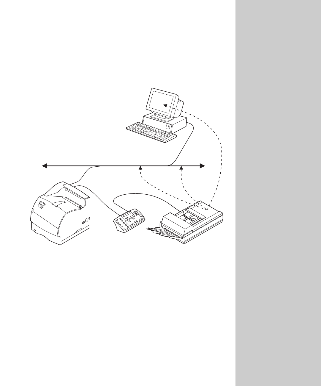
Network scanning overview
In addition to copy and fax functions, the OptraImage office solution lets you
scan documents back to your PC or to e-mail and FTP destinations on your
network.
PC on the
network
TCP/IP network
Printer with print
server installed
OptraImage
Control panel
The easiest method for sending a one-time scan job is to create a scan profile. PC
scan profiles let you send scanned documents in a file back to your PC. E-mail
scan profiles let you send the scanned documents attached to an e-mail, or store
them on a Web site and send only a Web link to the e-mail recipient.
Scan Unit
54
Page 63

For more explanation about
the settings, see “Custom Scan
to PC settings” on page 57.
Create Scan Profiles
Using the MarkNet resident web server, y ou ca n cre ate profiles for scan jobs
before you leave your workstation. A Scan Profile in clud es all the necessary
information about your originals and presets the OptraImage con trol panel to
those settings.
Scan documents back to your PC
Step 1: Set up your PC Scan Profile
Browse to the MarkNet resident web server.
1
2 Click Create Scan Profiles.
3 Click PC Scan Profile.
4 Set your scan job settings. The settings you assign can be overridden by
entering new choices on the control panel.
5 Click Next.
When creating your profile, click the Help button (i f available) for more
information. Help buttons are only available on some web pages.
55
Page 64

Step 2: Select a storage location on your PC
Specify a path and file name for saving the information somewhere on
1
your PC. For example, you can browse to your desktop, find the
appropriate directory, and type in a file name. When you are finished, an
entry similar to the following appears in the Save to dialog box:
C:\WINDOWS\DESKTOP\dc_test.pdf
2 Assign a Profile Name. This is the name that appears in the Scan → Profile
list in the OptraImage control panel.
3 Click Submit.
A Receiving Image window appears on your desktop indicating that your PC is
waiting to receive the scan job. When the job is finished, this window changes
to Image Received.
Once the job appears in the list, you can select it and launch an application to
open the file.
Step 3: Scan your original documents
Depending on the settings
elected, complex images may
take a longer time to s c an .
Check the Receiving Images
dialog on your PC f or the
status of the scan job.
PC Scan Profiles are not
stored. Once they are used,
they no longer appear in the
control panel.
1 Locate the network-attached OptraImage you want to use.
2 Load your document into the scan unit.
3 Find the scan job profile name in the OptraImage control panel. Press
Fax/Scan Mode repeatedly until you see
repeatedly until you see your job name.
Scan → Profile, and press Menu >
4 If you want to override your profile format settings, make those changes
now.
5 Press Go/Send to start sca nning.
Note: If you are using the flatbed of the scan unit, watch the control panel
for messages. When prompted to Place next or stop, press Go/Send to
scan multiple pages or press Stop/Clear to end the scan job.
6 Return to your PC. Your image should be saved in a directory or launched
in the application you specified.
This must be the OptraImage
using the MarkNet print
server. The IP address of the
MarkNet print server must be
the one you browsed to when
you created your scan job
profile.
56
Page 65
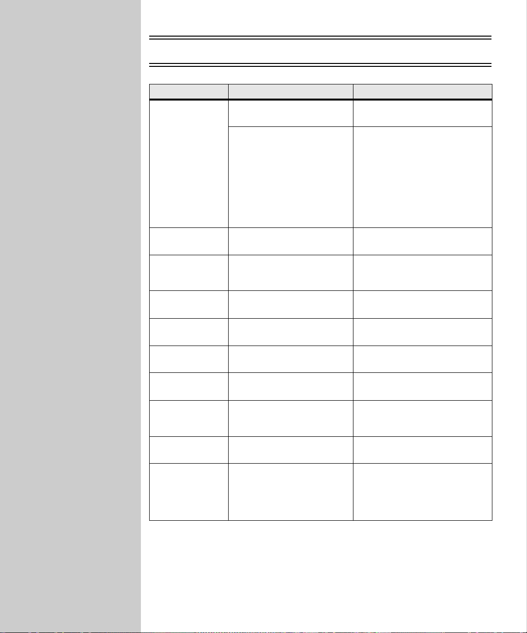
Custom Scan to PC settings
Menu Settings Description
Custom Lets you customize the scan job
Quick Setup
Format Type JPEG, PDF, TIFF Determines the final output
Compression None, JPEG, ZLib, G4 Determines the compression
Contrast Text, Mixed, Photo Describes the content of the
Scan Depth RGB, Gray, BW (Black and
Resolution 150, 200, 300, 400, 600 dpi Sets the resolution of the
Original Size Letter, Legal, A4 Tells the scan unit the paper size
Text Document --BW PDF
Text Document -- BW TIFF
Mixed Content -- Gray PDF
Mixed Content -- Color PDF
Photo -- Color JPEG
Photo -- Color TIFF
Photo -- Gray JPEG
Photo -- Gray TIFF
White)
settings.
List of preset formats.
Lets you only customize the
brightness, set the size of your
originals, and the orientation of
your scan file output.
(Color is only available if your
scan unit supports color)
format of the scanned document.
format used to compress the
scanned document output file.
originals being scanned.
Describes the color scale of the
originals being scanned.
scanned document output file.
of the originals being scanned.
Orientation Portrait, Landscape Determines the orientation of
Save to Type in the p ath or bro wse to
the location
Profile Name Type in a unique name Name that appears in the
your scanned document output
file.
Location path wher e scanned file
is to be located.
OptraImage control panel.
Select this name in the
OptraImage control panel to
activate the scan profile.
57
Page 66

Scan documents to e-mail
Step 1: Set up your E-mail Scan Profile
Browse to the MarkNet resident web server.
1
2 Click Create Scan Profiles.
3 Click E-mail Scan Profile.
4 Specify the recipient and the sender. You can assign a subject and add a
message to the content of the scan job.
5 Select the scan type, resolution, and size of the original. These settings can
later be overridden by entering new choices on the control panel.
6 Select whether the file is to be sent as an Attachment or as a Web Link.
• Attachment -- a copy of the scanned document is sent attached to the
e-mail message to the recipient
• Web Link -- the scanned document is sent to a storage area on a Web
site and a We b link to that site is sent to the e-mail recipient (can save
you from having to attach large scan jobs to email)
7 Assign a Profile name. After job is submitted, this name appears in the
OptraImage control panel.
8 Click Submit.
For more explanation about
the various settings, see
“Custom Scan to PC settings”
on page 57.
A maximum of ten profiles can
be stored. When the eleventh
profile is created, the oldest is
discarded.
Step 2: Scan your original documents
1 Locate the network-attached OptraImage you want to use.
2 Load your document into the scan unit.
3 Find the scan job profile name in the OptraImage control panel. Press
Fax/Scan Mode repeatedly until you see
Menu > repeatedly until you see your job name.
Scan → Profile, and then press
4 If you want to override your profile format settings, make those changes
now.
5 Press Go/Send to start sca nning.
Note: If you are using the flatbed of the scan unit, watch the control panel
for messages. When prompted to Place next o r stop , press Go/Send to
scan multiple pages or press Stop/Clear to end the scan job.
58
This must be the OptraImage
using the MarkNet print
server. The IP address of the
MarkNet print server must be
the one you browsed to when
you created your scan job
profile.
Page 67

Scan documents to permanent destinations
This must be the OptraImage
using the MarkNet print
server. The IP address of the
MarkNet print server must be
the one you browsed to when
you created your scan job
profile.
Once permanent e-mail and/or FTP destinations have been configured, the list
becomes available in the OptraImage control panel.
Take your original documents to the network attached OptraImage you want to
use and follow these steps:
1 Load your document into the scan unit.
2 Find the name of the e-mail recipient or the FTP server destination in the
OptraImage control panel:
a Press Fax/Scan Mode repeatedly until you see Scan → e-mail or
Scan → FTP.
b Press Menu > repeatedly until you see the name of your destination.
3 T o override the default format settings from your Scan to Network General
Setup, make those changes on the control panel now.
4 Press Go/Send to start the Scan to e-mail process.
Note: If you are using the flatbed of the scan unit, watch the control panel
for messages. When prompted to Place next or stop, press Go/Send to
scan multiple pages or press Stop/Clear to end the scan job.
View the destination lists
1 Browse to the MarkNet resident web server.
2 Click Reports.
3 Under the OptraImage heading, click the lin k of the list you want to view
such as FTP Destinations List.
Information about each destination is displayed.
59
Page 68

Print the destination lists
1 Locate the OptraImage. This must be the same OptraImage with the IP
address where the destination lists were created and stored.
2 Press Menu > repeatedly until you see DESTINATIONS, and then press
Select.
3 Press Menu > repeatedly until you see the list you want to print (for
example,
Information about each destina tion is contained in the list. The following
illustration is an example of one type of list.
Na me Ad dr es s Ty pe Sho rt cu t #
---------------------------- ----------- -------------------------------- ------------------- --------------Smith, Jane [email protected] Attachment 5
Smith, Jane2 [email protected] Web Link 6
Doe, John [email protected] Web Link 12
Print E-mail List), and then press Select.
E-Mail Destinations
Print the shortcut list
1 Locate the OptraImage. This must be the same OptraImage with the IP
address where the destination lists were created and stored.
2 Press Menu > repeatedly until you see SHORTCUTS, and then press Select.
3 Press Menu > repeatedly until you see Print List, and then press Select.
This is a numerically ordered list of all permanent destinations with assigned
shortcut numbers.
60
Posting the shortcut list close
to the OptraImage control
panel can reduce the time
spent searching for
destinations in one of the
menus.
Page 69

Appendix A:
Network Printing
MarkNet print server setup - - - - - - - - - - - - - - - - 62
Print a network setup page - - - - - - - - - - - - - - - - - - 62
Configure and print- - - - - - - - - - - - - - - - - - - - - - 62
TCP/IP - - - - - - - - - - - - - - - - - - - - - - - - - - 63
Novell NetWare - - - - - - - - - - - - - - - - - - - - - - 67
AppleTalk - - - - - - - - - - - - - - - - - - - - - - - - - 68
OS/2 Warp Server - - - - - - - - - - - - - - - - - - - - - 68
Solve network print problems - - - - - - - - - - - - - - - 69
TCP/IP - - - - - - - - - - - - - - - - - - - - - - - - - - 69
Novell NetWare - - - - - - - - - - - - - - - - - - - - - - 70
Windows NT Server 4.0 - - - - - - - - - - - - - - - - - - 71
AppleTalk - - - - - - - - - - - - - - - - - - - - - - - - - 72
Other network en vironments - - - - - - - - - - - - - - - 72
61
Page 70
MarkNet print server setup
Print a network setup page
1
During setup, you connected your printer to a network and assigned an IP
address. Verify that the correct TCP/IP and DHCP information is displayed on
the network setup page.
Use the printer operator panel to print the network setup page. (Hint: Network
Menu/Network Optio n x/Netwo r k x Setup/Pr int/Prin t S etup Page) This page shows
the physical address of the MarkNet print server (UAA) and other important
data. Save this page because you will use it later.
❏ If the IP address, netmask, and gateway are correct on the MarkNet
print server network setup page, skip to “Set up to print” on page 65.
❏ If the TCP/IP information on the setup page is not correct, go to the next
step and find the complete set of instructions for TCP/IP.
❏ To connect the printer to a network other than TCP/IP, go on to the next
step and find the configuration for your appropriate network.
For more information about
using the printer operator
panel, refer to your printer
documentation.
Configure and print
2
Network environment Page
TCP/IP
Novell NetWare
AppleTalk
OS/2 Warp Server
63
67
68
68
62
Page 71

For information about
configuring and printing on
other networks, refer to the
Drivers, MarkVision and
Utilities CD. Click View
Documentation and look for
the MarkNet link, and then
find your network
information.
For instructions on other ways
to set the IP address, look on
the Drivers, MarkVision and
Utilities CD. Click View
Documentation and look for
the MarkNet link.
“X” designates which option
slot in the printer is being
used. For example, if you
install the MarkNet print
server in option slot 2, the
operator panel selection would
be: Network Option 2.
About the Drivers, MarkVision and Utilities CD
You may have more than one version of this CD, received at different times
with different Lexmark products. Always use the latest version CD.
TCP/IP
Set the IP address, netmask and gateway
You must assign an IP address, netmask and gateway to the MarkNet print
server for other network devices to find the printer on the network.
❏ If you have DHCP, the proper address values are automatically
assigned. Look for the information on your MarkNet print server
network setup page.
❏ If you don’t have DHCP, there are other methods you can use to
manually assign address values, such as the printer operator panel,
static ARP and telnet, RARP and telnet, BOOTP, MarkVision or other
Lexmark utility. Instructions for three of these methods follow.
Printer operator panel
A simple way to set the IP address, netmask and gateway inside the print server
is to use the printer operator panel. You need to be standing at the printer to use
this method.
1 On the printer operator panel, choose Network Menu, Network Option X,
Network X Setup, TCP/IP, Set IP Address. (Hint: Press Menu> until you see
the right menu item, and then press Select.)
2 When the current IP address is displayed, use the buttons to change the
address. (Hint: Press Select to advance t o the next segment in the address. Press
Menu> to increase the number by one. <Menu decreases the numb er by one.)
3 Repeat steps 1 and 2 to set the netmask and gateway.
4 When you finish setting the IP address, press Select until the word SA VED
appears briefly. Print a new network setup page to verify the parameters
are set as you intended.
63
Page 72

Static ARP and teln et
Use this method from any Windows, OS/2, or UNIX workstation. You need to
know the physical address of the MarkNet print server to use this method.
1 Find the physical addr ess (UAA) of the Mark Net print server (fo r example,
00200022012F) on the network setup page you printed earlier. If you have
an Ethernet network, use the number in the right column (canonical). If
you have a Token-Ring network, use the number in the left column (MSB).
2 Set the IP address in your workstation ARP table. At a command prompt,
type a command similar to the following, inserting the IP address you
want to assign and the UAA:
arp -s 192.168.236.24 00-20-00-22-01-2F
3 Set the IP address, netmask and gateway in the print server. To do this,
telnet to port 9000 on the MarkNet print server by typing a command
similar to the following:
telnet 192.168.236.24 9000
4 Verify the print server is up and running on the network.
ping 192.168.236.24
Print server TCP/IP setup utility
Use this simple utility to initialize the IP address if your workstation is running
Windows 95, Windows 98 or Windows NT. You ne e d the 12-digit physical
address of the print server to use this method.
To install the utility, launch the Drivers, Ma rkVision and Utilities CD, do a
custom install to add network support, and then select Print Server TCP/IP
Setup Utility.
The UAA is a 12 digit
number. The left column is the
number given in MSB form
and the right is canonical.
The workstation and the
printer must be on the same
subnet.
It doesn’t matter which form of
the UAA you use (MSB or
canonical).
Information on installi n g ,
using and trouble s h ooting the
utility is on the CD.
Link to the
MarkNet
resident web
server
Once the IP address has been set (using any method),
you can use your browser to remotely view and
manage the network printer. Functions include
viewing printer status in real time, resetting the
printer, changing settings, and so forth. Type the IP
address of the MarkNet print server in the URL field
of the browser (for example, http: //192.168.236.24),
and then press Enter.
64
Page 73

If you are using Windows NT
Server 4.0 or later and
running TCP/IP, you can use
Network Plug and Print to
automate your printer setup
process.
Set up to print
There are many ways to send a print job, including FTP, TFTP, LPR/LPD ,
point-to-point (LexIP) and various queue-based methods. Instructions for two
of the methods follow.
Print to a queue on a Windows NT server
This section explains the setup for queue-based printing where network users
print to a queue defined on a Windows NT server. The MarkNet print server
services this queue. To use this method, you must have at least one server
running Windows NT Server software and TCP/IP.
The following instructions apply to Windows NT Server versions 4.0 and later.
1 Install the TCP/IP software component on the server that contains the
print queue. This software is necessary to establish the link between the
MarkNet print server and the queue. Look on the Drivers, MarkVision and
Utilities CD for the software. (Hint: Do a custom install to add network
support, and select TCP/IP.)
2 Set up a print queue on the server. Do this by creating a printer object.
a Click Start, Settings, Printers, Add Printer.
b When prompted, select My Computer (not Network printer server).
c Click Add Port.
d Select Lexmark Network Port, and then click New Port. Follow the
instructions on the screen.
e Share the queue.
3 Set up your Windows 95, Windows 98, or Windows NT clients in the usual
way. ( Hint: Start, Settings, Printers, Add Printer.)
65
Page 74

Point-to-point printing (LexIP)
You can print from any Windows 95, Windows 98 or Windows NT workstation
directly to a Lexmark printer located anywhere on the IP network. No server is
required.
1 Install the TCP/IP software component on the workstation. Look on the
Drivers, MarkVision and Utilities CD for the software. (Hint: Do a custom
install to add network support, and select TCP/IP.)
2 Create a printer object on the workstation:
a Click Start, Settings, Printers, Add Printer.
b Windows 95/98: When prompted, select Local Printer (not Network).
This gives you access to the Lexmark Network Printer Monitor later.
Windows NT: When prompted, select My Computer (not Network
Printer Server). This gives you access to the Lexmark Network Prin ter
Monitor later.
c Select the correct printer driver.
d Select any port (LPT, COM, or FILE) for the initial setup. Later, you will
change the port to a logical port.
e Click Next, and then continue following the instructions on the screen
until the printer object has been created.
3 Associate the printer object with the physical printer.
a Select the newly created printer object in the printers folder.
You can obtain the latest
Lexmark printer drivers from
our Web site at:
www.lexmark.com.
b Windows 95/98: Click File, Properties, Details, Add Port.
Windows NT: Click File, Properties, Ports, Add Port.
c Click Other, Lexmark Network Printer Monitor, and then click OK. A
list of available print servers is shown. If your print server does n ot
appear in the list, click Add Adapter and then follow the instructions
on the screen until it appears.
d Find the IP address of your print server in the list, and then select it.
e Specify a logical port name to associate with the printer, and then click
OK.
f Verify that the logical port name you assigned to the printer now shows
in the box labeled Print to the following port.
g Click OK.
66
You can print from DOS
using LexIP if you assign a
logical port name of LPT1,
LPT2, LPT3 or LPT4.
c:\>copy FileName LPT3
Page 75

On the Drivers, MarkVision
and Utilities CD, look for a
subdirectory named NDPS.
This subdirectory contains the
NDPS gateway files and all
supporting documentation
(README file and an
instructional white paper).
The default login name
contains the characters
!LEX plus the UAA
of the MarkNet print
server (for example,
!LEX00200022012F).
Novell NetWare
NDPS (Novell Distributed Print Services)
If you have MarkNet print servers in an NDPS environment, we recommend
that you install the Lexmark NDPS IP Gateway. Your printers are integrated
with NDPS so you can easily monitor, control and print to them. You can get
the gateway plus all support files and installation procedures from the Lexmark
Web site (www.lexmark.com) or from some versions of the Drivers,
MarkVision and Utilities CD.
Non-NDPS (queue-based)
The easiest way to configure the print server for NetWare jobs in a non-NDPS
environment is to use MarkVision. MarkVision can automatically create all the
necessary NetWare objects (print queue objects, print server objects, and printer
objects).
Do the following from a Windo ws NT workstation running Novell NetWare
Client32 software, or from a Windows 95 or Windows 98 workstation running
either Novell Client32 or Microsoft Client for NetWare networks.
1 Install the NetWare software component on the workstation. Look on the
Drivers, MarkVision and Utilities CD for the software. (Hint: Do a custom
install to add network support, and select NetWare.)
2 Launch MarkVision. In the MarkVision main window, find the new
network printer. Look for the line item containing your print server’s
physical address (the MSB form of the print server UAA).
3 Double-click the network printer. Configure the MarkNet print server by
doing the following:
a Set a unique NetWar e login name. This is the name the print server uses
to log in to the NetWare server.
b Enable the MarkNet print server port.
For information about
choosing PSERVER or
RPRINTER mode, look on the
CD. Click View
Documentation and look for
the MarkNet link.
c Select PSERVER mode.
• To manage NDS queues, specify the NDS tree and context where
the MarkNet print server is defined. Afterwards, create or select
queues to be serviced.
• To manage bindery queues, specify the file servers. Afterwards,
create or select queues to be serviced.
4 If prompted to reset the print server, select Yes to im med ia tely begin
servicing the queues.
67
Page 76

AppleTalk
The MarkNet print server works automatically wit h AppleTalk networks. You
simply connect the power and the network cables. However, if you would like
to use a zone and printer name different from the defaults you can use
MarkVision for Macintosh to change these settings.
Each Macintosh user on the AppleTalk network should do the following:
1 In the Chooser, select the LaserWriter 8 driver.
2 If you have a routed network, there is a list of zones you can select from.
The new printer is in the default zone for the network. Select this zone. If
you don’t know which zone to select, look on the network setup page
under AppleTalk for Zone.
3 Select the new printer. If you don’t know which printer to select, look on
the network setup page under AppleTalk. The default name of the printer
is listed beside Name.
4 Click Create.
5 If you are prompted to select a PPD (PostScript Printer Description), you
need to install the proper PPD from the Drivers, MarkVision and Utilities
CD. To do this, launch the CD, click Lexmark Installer, select the
appropriate PPD for your printer, and then click Install. Go back to the
Chooser and try to create the new printer again.
6 Look for an icon to appear in the Chooser next to the printer name. This
means you have successfully set up the new printer. A new desktop
printer icon is placed on your desktop, too.
7 In the Chooser, select the printer you want to use now and close the
Chooser window.
MarkVision for Macin t os h
resides on the Drivers,
MarkVision and Utilities CD.
A PPD describes the printer or
printer family. For example,
the PPD lists which options
are valid for the printer.
OS/2 Warp Server
MarkNet print servers work on OS/2 Warp Server networks. Users can print to
the network printer from any client that can successfully attach to the network.
For instructions on configuring the print server for OS/2 networks, look on the
Drivers, MarkVision and Utilities CD. Click Vi ew Documentation and look for
the MarkNet link.
68
Page 77

The file you use with FTP can
be in PCL or PostScript
emulations, PDF, HTML or
any other language the printer
understands. If the file prints,
this confirms the TCP/IP
protocol is working prop erly in
the MarkNet print server.
To invoke the browser-based
utility, type the IP address of
the MarkNet print server in
the URL field of the browser
and press Enter.
Solve network print problems
For additional troubleshooting info rmation, look on the Drivers, MarkVision
and Utilities CD. Click View Documentation and look for the MarkNet link .
TCP/IP
1 Make sure the TCP/IP protocol is turned on (activated) in the print server.
To find out, print a network setup page and look under TCP/IP.
2 Issue a ping command to the print server.
ping 192.168.236.24
3 Establish an FTP session with the print server.
ftp 192.168.236.24
4 Using the FTP put command, print a file to the network printer.
put mytest.ps
5 Check the port settings on the printer object.
6 Check all settings in the print server, using the browser-based utility or
MarkVision.
7 For non-UNIX networks: Uninstall Lexmark software.
8 For non-UNIX networks: Reinstall Lexmark software. During the
reinstallation, select only those network protocols you actually use (for
example, TCP/IP).
9 Try printing again.
10 If you are still having trouble, call the Lexmark Customer Support Center.
See “Customer Support” on page 107.
69
Page 78

Novell NetWare
NDPS (Novell Distributed Print Services)
1
Make sure the TCP/IP protocol is turned on (activated) in the print server.
To find out, print a network setup page and look under TCP/IP.
2 Make sure your NetWare file server has TCP/IP support configured and
loaded.
3 Make sure you are running NDPS version 2.0 or later.
4 Make sure you’ve created and loaded an NDPS Manager.
5 Read the online documentation about Lexmark’s NDPS support. Look for
a README file or a technical white paper either on the Drivers,
MarkVision and Utilities CD or in the package you downloaded from
Lexmark’s Web site .
6 If you are still having trouble, contact Lexmark for help. See “Customer
Support” on page 107.
Non-NDPS (queue-based)
1
Make sure the NetWare protocol is turned on (activated) in the print server.
To find out, print a network setup page and look under NetWare.
2 Find out if the print server is servicing your NetWare queue.
3 If your queue doesn’t appear in the list of queues being serviced, reset the
printer, wait a few minutes, and then look for the queue again.
4 If your queue still does not appear in the list of queues being serviced, you
have a print server setup problem. Reconfigure the MarkNet print server.
5 Try printing from some other application. If the job prints from the second
application, you’ve narrowed the problem to the first application. Make
sure you are using the current version of the driver for the problem
application.
6 Place a job in the queue using a Novell utility such as PCONSOLE. If the
job doesn’t print, conta c t L e xmark for help. See “Customer Support” on
page 107.
70
Page 79

The file you use with FTP can
be in PCL or PostScript
emulations, PDF, HTML or
any other language the printer
understands. If the file prints,
this confirms the TCP/IP
protocol is working prop erly in
the MarkNet print server.
Windows NT Server 4.0
1 Make sure you are using TCP/IP for communications between the
Windows server and the MarkNet print server.
2 Make sure TCP/IP is turned on (activated) in the print server. To find out,
print a network setup page and look under TCP/IP.
3 Verify that TCP/IP is installed properly on the Windows server. (Hint:
Start, Settings, Control Panel, Network, Protocols).
4 Issue a ping command to the print server.
ping 192.168.236.24
5 Establish an FTP session with the print server.
ftp 192.168.236.24
6 Using the FTP put command, print a file.
put mytest.ps
7 See if the network printer shows up in MarkVision.
• If it doesn’t, the print server may have downlevel firmware.
• If it does but you still cannot prin t, try removing and then
re-adding the Lexmark Network Port on the printer object.
8 Reset both the print server and the printer.
9 If possible, shut down Windows NT Server and restart the server. There
could be a spooler problem that requires a restart.
10 Uninstall, and then reinstall MarkVision. During the reinstallation, select
only the network protocols you actually use (for example, TCP/IP ). Thi s
also helps MarkVision run faster.
11 Try printing again.
12 If you are still having trouble, contact Lexmark for help. See “Customer
Support” on page 107.
71
Page 80

AppleTalk
1 Make sure the AppleTalk protocol is turned on (activated) in the print
server. To find out, print a network s etup page and look under AppleTalk.
2 Make sure the status of the MarkNet print server is “connected”. To find
out, look on the netw ork setup page for Status.
3 Do you see the printer in the Chooser? If not, restart the Macintosh
workstation and look again.
4 If you still don’t see the printer in the Chooser, make sure AppleTalk is
active on the workstation (look in the AppleTalk control panel).
5 If the job prints but the print quality is poor, refer to the printing tips
provided on the CD. These tips can save you a lot of time. To download the
document to your workstation, launch the CD, click Lexmark Installer,
select Documentation, and then click Install. Loo k in the Lexmark Extras
folder for the document titled Optimize Lexmark Printer Output.
6 If you are still having trouble, contact Lexmark for help. See “Customer
Support” on page 107.
Other network environments
If you’re on a non-routed
network, you can only see the
printer if your workstation
connection (LocalTalk,
Ethernet or Token-Ring)
matches the connection on the
printer. For example, if the
Macintosh workstation is on
LocalTalk, you cannot see a
printer on Ethernet unless
there is a router on the
network.
For troubleshooting information about other network enviro nments, look on
the Drivers, MarkVision and Utilities CD. Click View Documentation and look
for the MarkNet link.
72
Page 81

Appendix B:B:
Job Accounting
Track OptraImage usage- - - - - - - - - - - - - - - - - - 74
Create accounts and set restrictions- - - - - - - - - - - - - - 74
Select a Courtesy tracking mode - - - - - - - - - - - - - - - 75
73
Page 82

Track OptraImage usage
MarkTrack™ is software that combines the unique capabilit ies of Lexmark
network printers and MarkVision™ software with an Oracle™ database.
Job Accounting provides MarkTrack users with the ability to accumulate
statistics on copy jobs, outgoing faxes, and scan to network jobs by requiring
OptraImage users to enter a Job Account number on the control panel or choose
a valid Job Account name from a list before being allow e d to sca n documents.
Create accounts and set restrictions
To use Job Accounting to track jobs:
• Create Job Accounts for each authorized OptraImage user.
• Notify each user to enter the assigned Job Account number on the control
panel to be allowed to scan.
For information about setting up this funct ion, see Chapter 1: Setup, “Create or
add a Job Account” on page 28 and “Require all scan jobs to be validated” on
page 29.
Note: Validation mode, when used with MarkTrack, collects statistical data
about copy jobs, scan jobs, and outgoing faxes. However, even if you
don’t use MarkTrack, Validation mode can be used to restrict
OptraImage usage to authorized individuals. Courtesy modes can also
be used to restrict usage, but none are as secure as Validation mode.
To count outgoing faxes, you
must be using a
MarkNet N2501e print server
containing a fax modem port.
74
Page 83
Select a Courtesy tracking mode
1 Browse to the MarkNet resident web server.
2 Click Configuration.
3 Click OptraImage Job Accounting.
4 Select one of the Courtesy modes.
Mode Description
Job Acntg. Off This is the default mode.
Courtesy I Enter an account number on the keypad before the control
Courtesy II There are two methods of entering Job Account information:
Courtesy III There are two methods of enter ing Job Account in formation on
Validation Sets the most security for using the OptraImage control panel.
panel accepts the job information.
The number is not checked against the master Job Account list .
• Enter an account number on the keypad before the control
panel accepts the job information.
• A valid account can also be entered by selecting a name
from the active Job Account menu on the OptraImage
control panel. Press Menu > or < Menu repeat edly until
the name associated with the account is displayed in the
control panel, and then press Select.
the control panel:
• Enter an acco unt number on the control panel keypad;
however, for increased security the account is checked
against the master list and validated.
• A valid account can also be entered by selecting a name
from the active Job Account menu on the OptraImage
control panel. Press Menu > or < Menu repeat edly until
the name associated with the account is displayed in the
control panel, and then press Select.
Enter an account number using the keypad on the OptraImage
control panel. The account is checked against the master Job
Account list and validated before the control panel accepts a
scan job. This choice does not allow a name to be selected from
the Job Account menu.
5 Specify a timeout. The timeout is the amount of time that passes after a
scan job is completed before the control panel is relocked.
6 Click Submit.
75
Page 84

76
Page 85

Appendix C:
Scan Unit
Support
General information - - - - - - - - - - - - - - - - - - - - 78
List of originals not usable in an ADF - - - - - - - - - - - - 78
Information about your scan unit- - - - - - - - - - - - - - - 78
Solve scan unit problems - - - - - - - - - - - - - - - - - 79
OptraImage 212/222, 312/322, Color 1200, T612 - - - - - - - 79
OptraImag e 514/524 - - - - - - - - - - - - - - - - - - - - - 80
OptraImag e 715/725 a n d W810 - - - - - - - - - - - - - - - - 81
Cleaning and maintenance- - - - - - - - - - - - - - - - - 82
OptraImage 212/222, 312/322, Color 1200, T612 - - - - - - - 82
OptraImag e 514/524 - - - - - - - - - - - - - - - - - - - - - 84
OptraImag e 715/725 a n d W810 - - - - - - - - - - - - - - - - 85
Replacement parts - - - - - - - - - - - - - - - - - - - - - 90
OptraImage 212/222, 312/322, Color 1200, T612 - - - - - - - 90
OptraImag e 514/524 - - - - - - - - - - - - - - - - - - - - - 91
OptraImag e 715/725 a n d W810 - - - - - - - - - - - - - - - - 92
77
Page 86

General information
Information about your scan unit
You purchased You have this
OptraImage 212/222 Avision 810c
OptraImage 312/322 Avision 820c
OptraImage 514/524 Ricoh ISO1
OptraImage 715/725 Fujitsu M3097DG
OptraImage Color 1200r/Color 1200p Avision 820C
OptraImage W810s/W810p Fujitsu M3097DG
OptraImage T612s/T612p Avision 820C
List of originals not usable in an ADF
The following cannot be properly fed by the ADF:
• Paper with clip or staple attached
• Paper with ink not totally dry
• Paper with inconsistent thickness, such as envelopes
• Paper with wrinkles, curls, folds or tears
• Tracing paper, coated paper, carbonless paper
• Paper that is too large or too small (use flatbed instead)
• Items other than papers, such as cloth, metal or OHP film
• Notched paper
• Paper with an odd (non-rectangular) shape
• Photographic paper
• Paper with perforations on its side
• Very thin paper
78
The ADF is the automatic
document feeder.
If you are unsure if the
document can be used in the
ADF, we recommend that you
scan it using the flatbed.
Page 87
Solve scan unit problems
OptraImage 212/222, 312/322, Color 120 0, T61 2
Problem Solution
Paper jams during scanning 1 Open the ADF unit.
2 Pull out the jammed paper carefully.
3 Close the ADF unit.
See “Clearing a paper jam in the ADF” on
page 80.
More than one sheet of paper was
fed into the scan unit
Paper skewed in the scan unit
When I power on the scan unit, it
makes noises and will not stand
ready
1 Open the ADF unit.
2 Remove the multifed sheets of paper.
3 Close the ADF unit.
4 Flatten the paper corners and edges;
loosen the paper before r eload ing it in the
paper guide.
5 Check the feeding roller condition. Clean
if necessary.
• Check the feeding roller condition. Clean
if necessary.
• Use the paper guide when feeding the
paper.
Make sure you:
• Remove the shipping retainer from the
scan unit.
• Place the scan unit on a flat desktop
surface.
79
Page 88
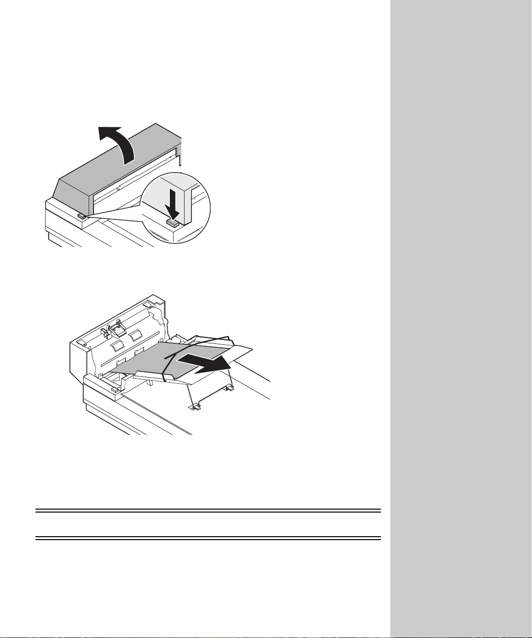
Clearing a paper jam in the ADF
Tu rn off and disconnect the power to the scan unit.
1
2 Open the ADF to its full position.
3 Carefully pull out the jammed piece of paper.
4 Close the ADF.
5 Connect the power and turn the scan unit back on.
OptraImage 514/524
For information about solving problems and other support, refer to the scan
unit documentation that shipped with y our OptraImage.
80
Page 89
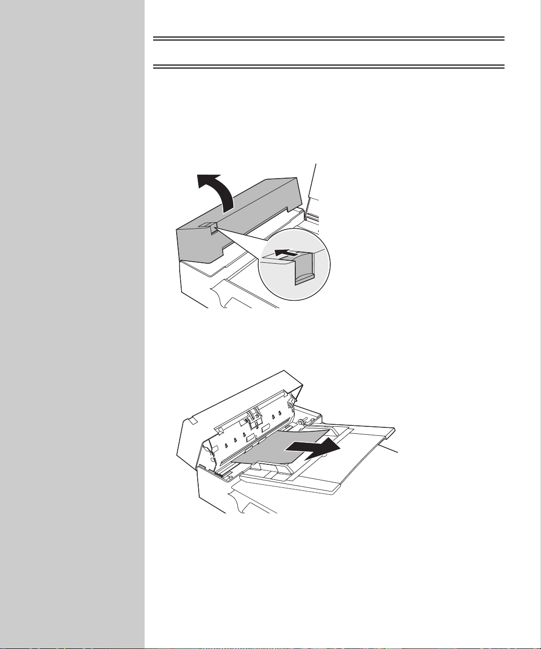
OptraImage 715/725 and W810
Clearing a paper jam
1
Remove any remaining originals from the ADF paper chute.
2 Open the ADF.
3 Remove the jammed documents. Be careful not to dislodge the ADF pad
assembly spring.
4 Check the paper path to see if any staples, paper clips, or other materials
may have caused the jam.
5 Close the ADF.
81
Page 90
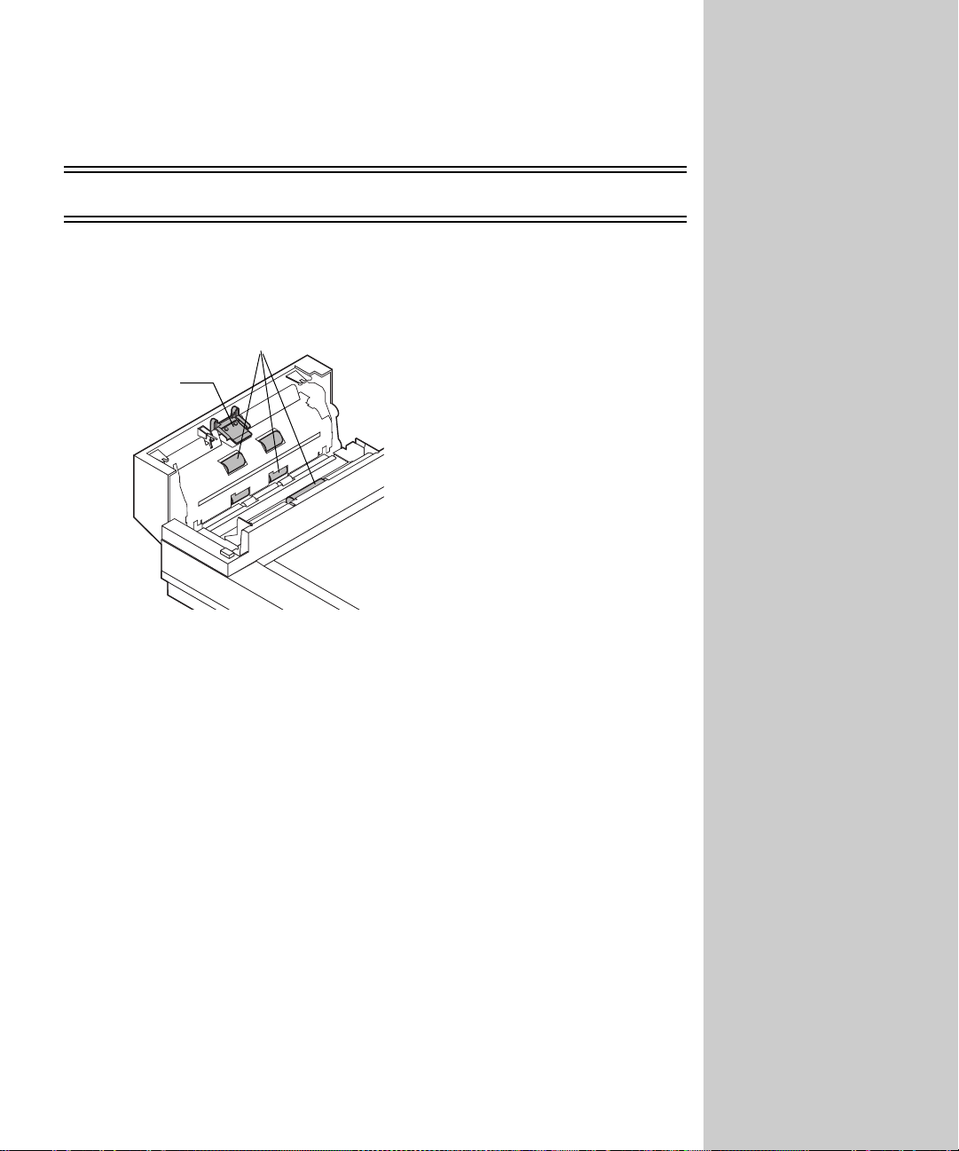
Cleaning and maintenance
OptraImage 212/222, 312/322, Color 120 0, T6 12
Cleaning the ADF
Feeding roller
Pad assembly
Clean the scan unit if documents do not feed smoothly or easily, or if several
documents feed at one time. The scan unit parts may be contaminated with ink,
toner particles or paper coatings.
1 Wet a clean , lint-free cloth or cotton swab with Isopropyl alcohol (95%).
2 Open the ADF unit and wipe the upper feeding roller by moving the swab
from side to side.
3 Rotate the roller forward with your finger and repeat the above cleaning
procedures until the entire roller is cleaned. Be careful not to snag or
damage the pick springs.
4 Wipe the pad in the direction from top to bottom. Be careful not to hook
the pick springs.
5 Close the ADF unit. You r scan uni t is now ready for use.
82
Page 91
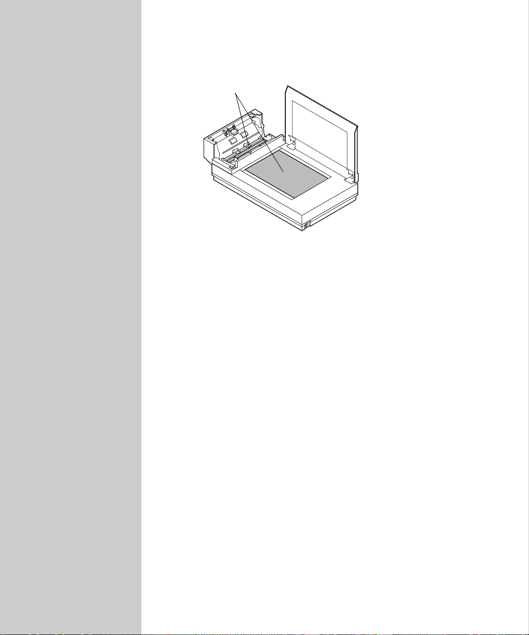
Cleaning the document glass
Glass
1
Wet a clean, lint-free cotton cloth or swab with some Isopropyl alcoh ol
(95%).
2 Open the ADF unit and document cover as shown. Wipe the glass of
flatbed and ADF area by moving the cloth or swab from side to side.
3 Close the ADF unit and document cover. Your scan unit is now ready for
use.
Moving the scan unit
If you need to transport the scanner, follow these instructions to refit the
shipping retainer:
1 Turn off the sc anner.
2 Raise the document cover to see the flatbed glass as well as the reading
engine.
3 Turn on the scan unit. The reading engine moves a few inches forward and
stays there for a few seconds. Turn off the scanner during this pause.
83
Page 92
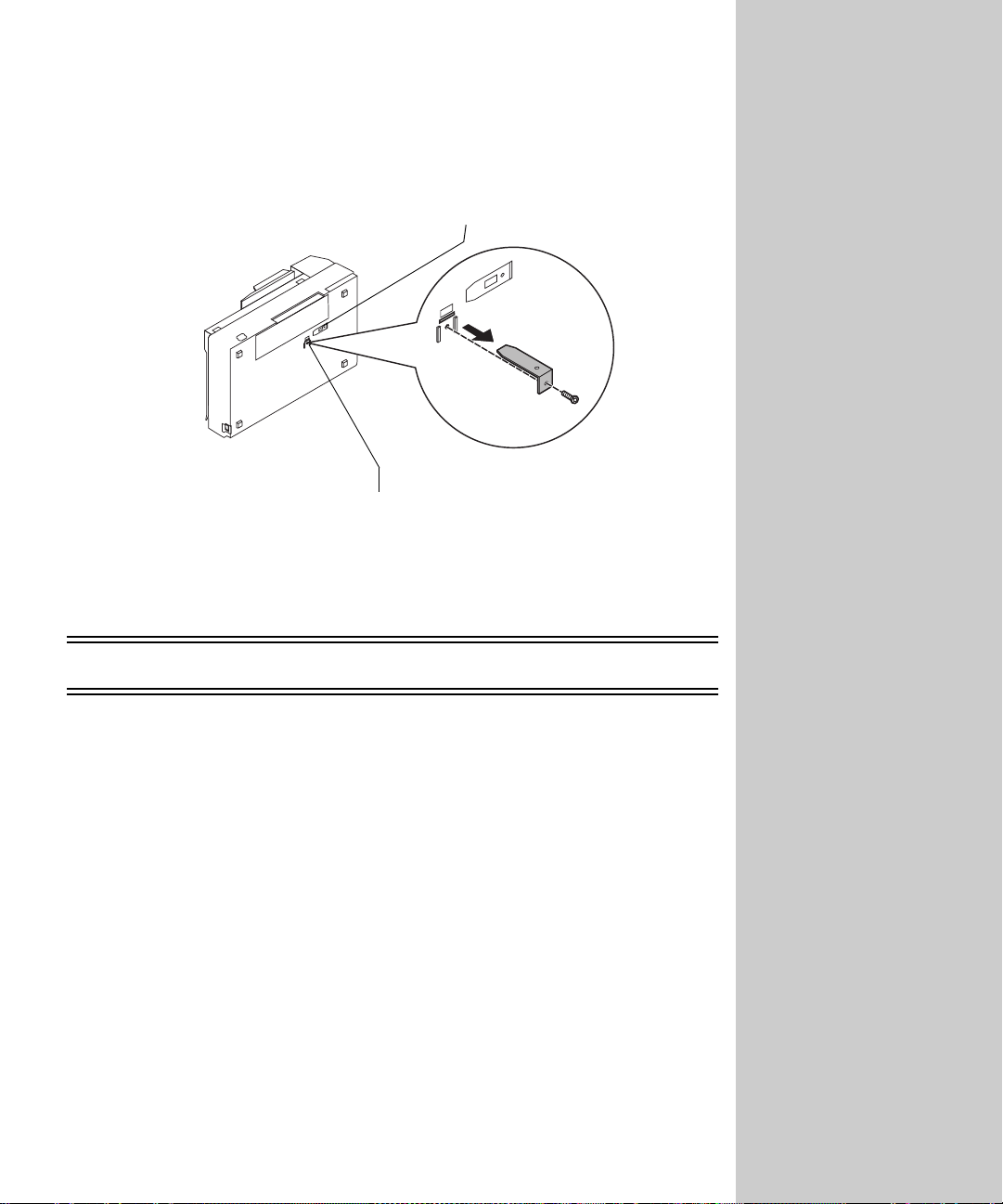
4 Raise the scanner high enough to unscrew the shipping retainer from the
use position and place it back into the shipping position.
Use position
Shipping position
OptraImage 514/524
For information about cleaning, maintenance and other support, refer to the
scan unit documentation that shipped with your OptraImage.
84
Page 93
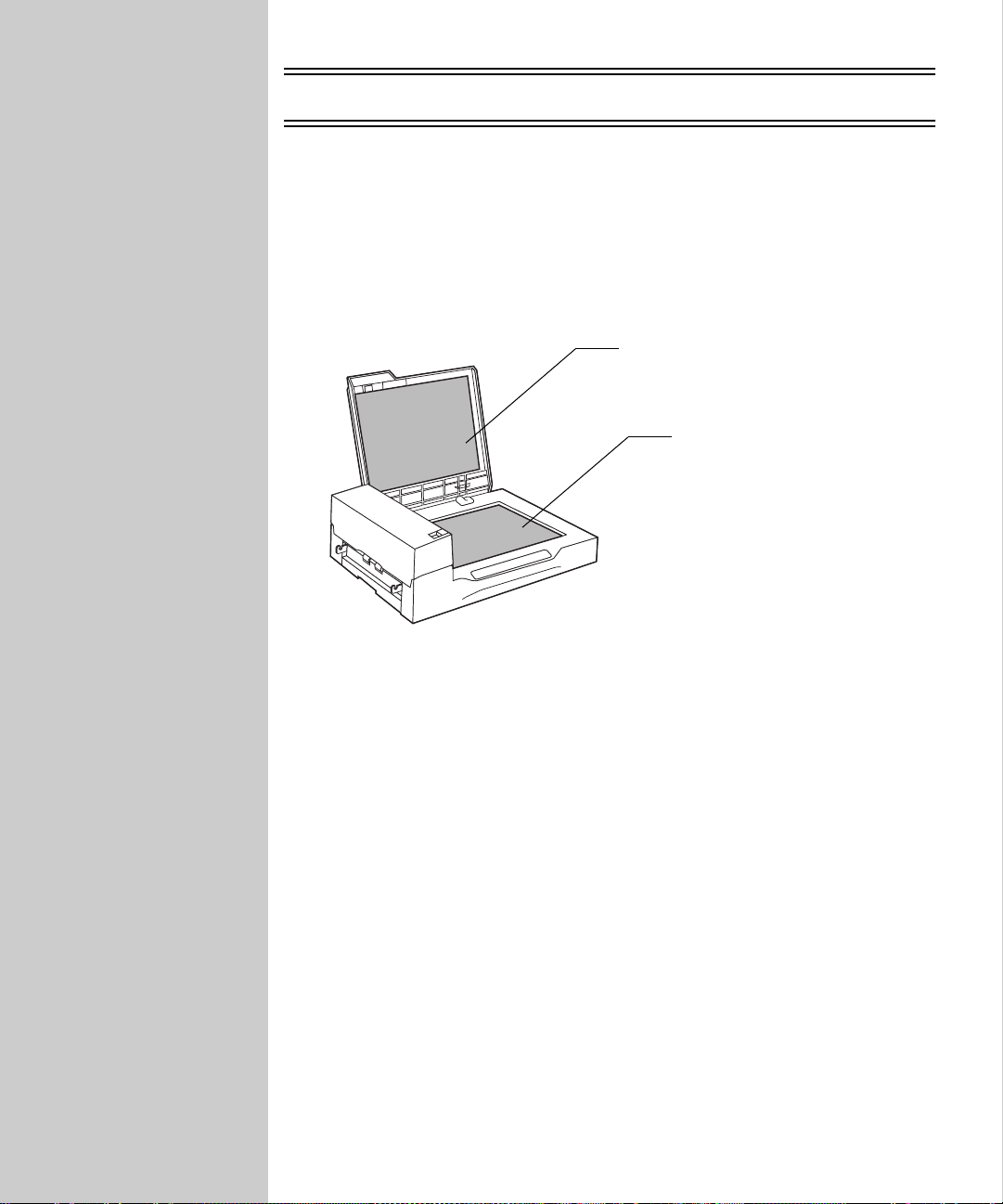
OptraImage 715/725 and W810
Cleaning the flatbed
1
Open the document cover.
2 Wipe the document holding pad and document bed with a clean cloth
dampened with Isopropyl alcohol (95%).
Document
holding pad
Document bed
3 Let it dry completely before scanning.
85
Page 94
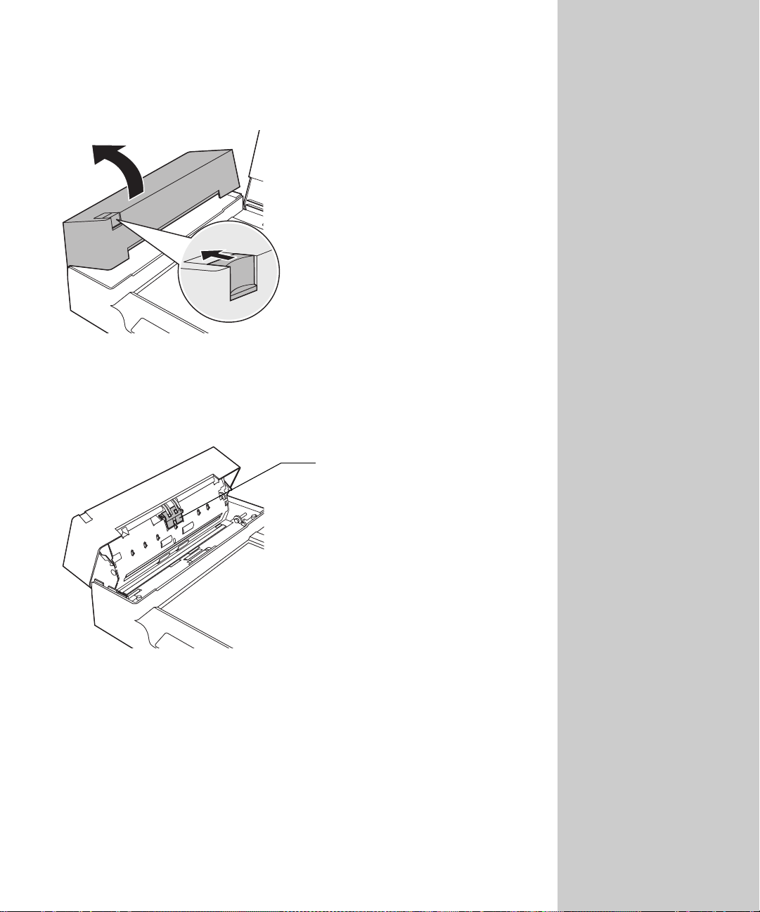
Cleaning the ADF
Open the ADF.
1
2 Clean the pad assembly by wiping in a downward motion using a dry
cloth or a cloth dampened with Isopropyl alcohol (95%). Be careful not to
damage the pick spring.
Pad assembly
86
Page 95
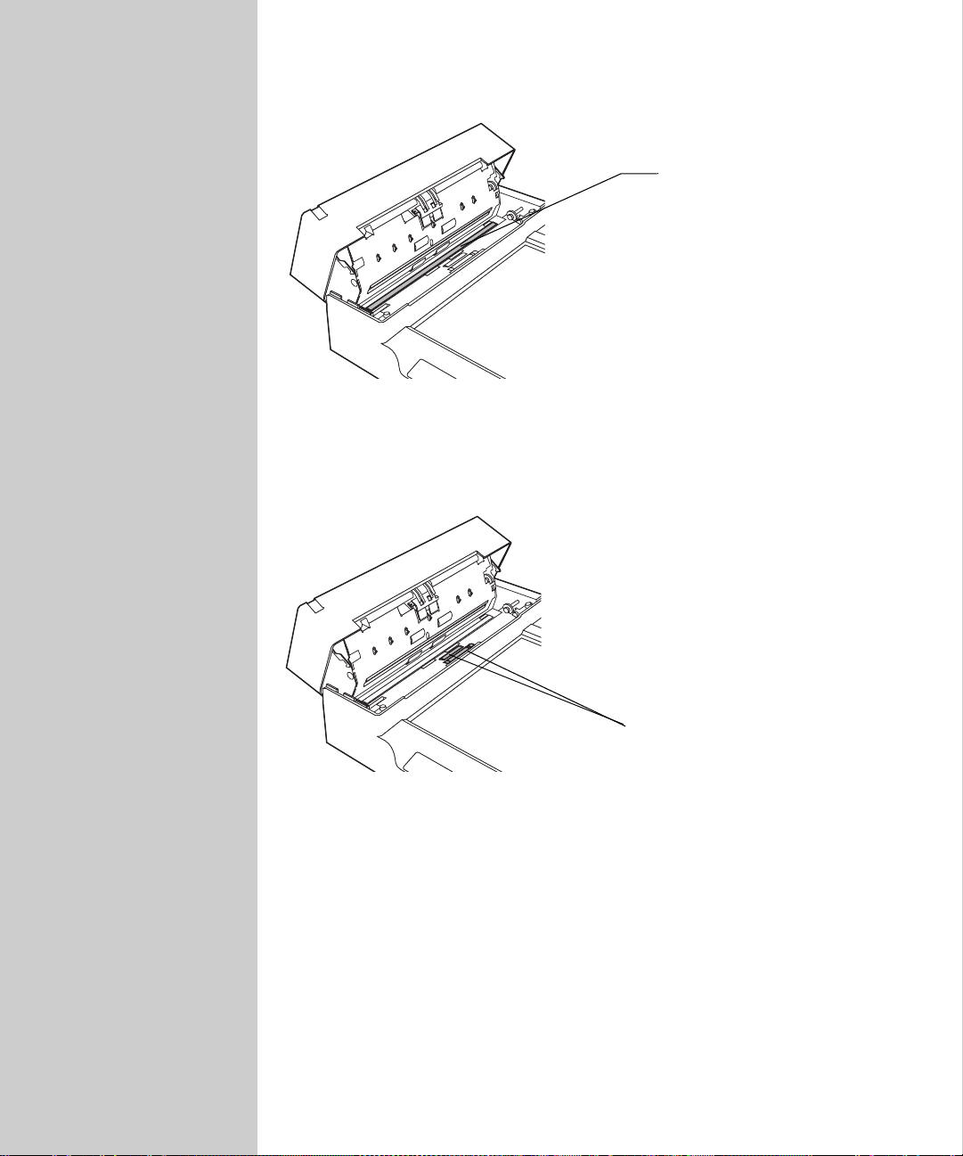
3 Wipe the glass lightly to clean it.
Glass
4 Wipe the pick roller. Be careful not to damage the surface of the roller or
mylar strip above it.
87
Pick roller
Page 96
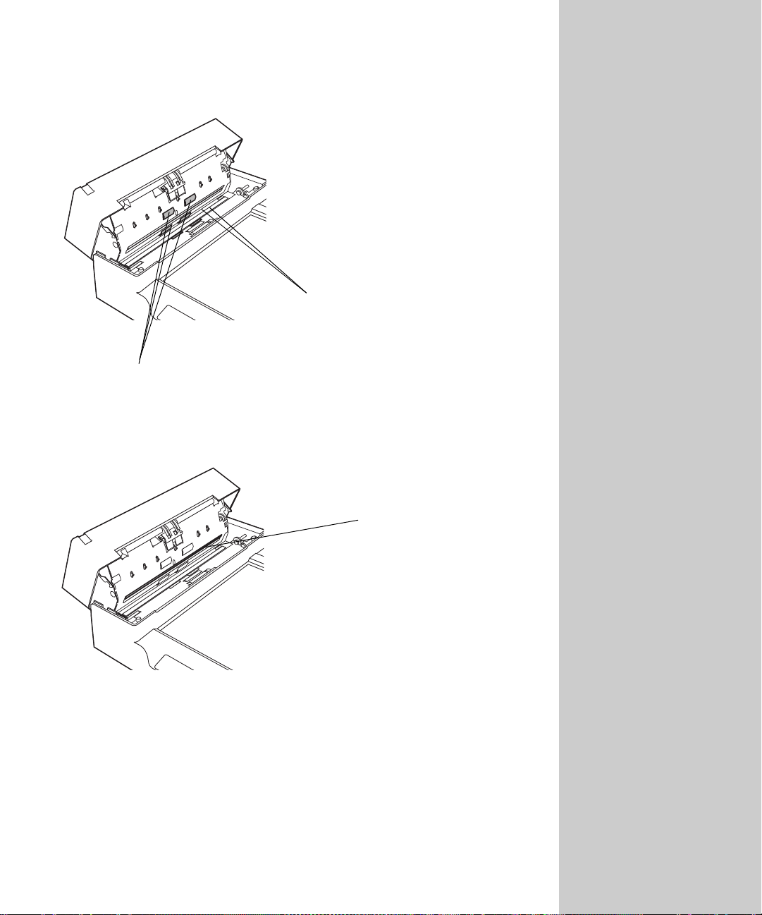
5 Wipe the feed rollers and the plastic rollers. Be careful not to damage their
surfaces.
Plastic rollers
Feed rollers
6 Wipe the sheet guide (white strip).
7 Close the ADF.
Sheet guide
88
Page 97
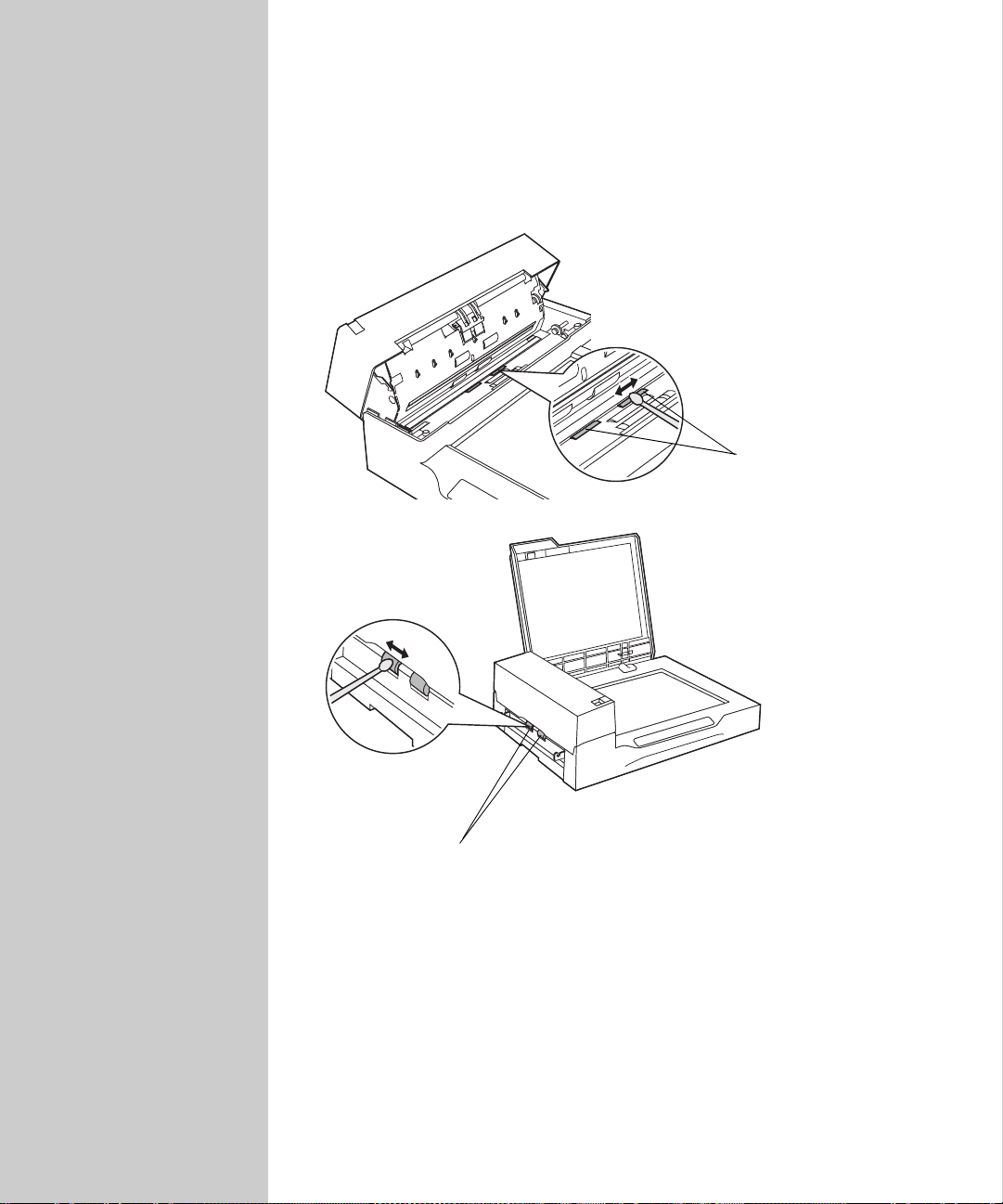
Cleaning the small plastic rollers
Open the ADF.
1
2 Wet a cotton swab with Isopropyl alcohol (95%).
3 Wipe the surfaces of the plastic rollers.
Small plastic rollers
Small plastic rollers
4 Let all surfaces dry completely before scanning.
89
Page 98
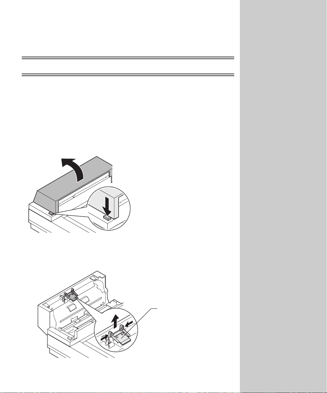
Replacement parts
OptraImage 212/222, 312/322, Color 120 0, T6 12
Replacing the ADF detachable pad assembly
The ADF detachable pad assembly (P/N 1 2G0188) has a frequency life of
150,000 scanned pages. You may experience difficulty with document feeding
when the pad wears out. The worn out pad needs to be replaced with a new
one.
1 Open the ADF front cover.
2 Remove the old ADF detachable pad assembly by pulling out the upper
part of the pad clamp.
To purchase replacement
parts, contact Lexmark or the
place where you purchased
OptraImage. For information
about contacting Lexmark, see
“Customer Support” on page
107.
ADF detachable pad
assembly
90
Page 99
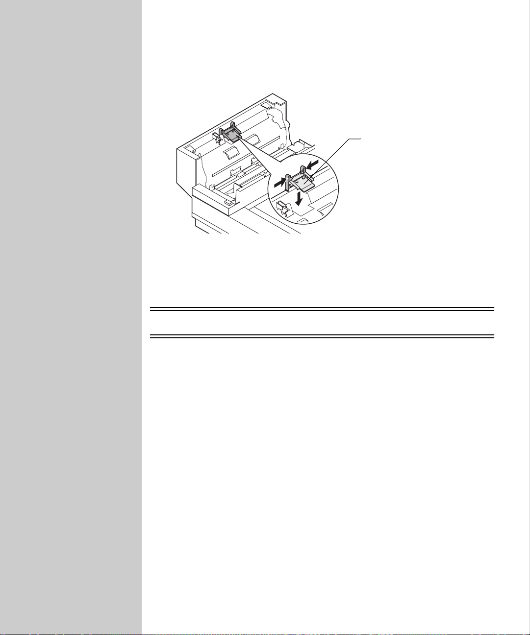
3 Hold the upper part of the new pad clamp, and place it gently in the pad
holder.
ADF detachable pad
assembly
4 Close the ADF.
OptraImage 514/524
For information about replacement parts and other support, refer to the scan
unit documentation that shipped with your OptraImage.
91
Page 100
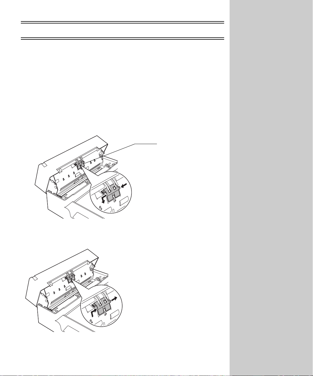
OptraImage 715/725 and W810
Replacing the pad assembly
The life expectancy of the ADF pad assembly (P/N 12G1835) is approximately
100,000 scanned pages or one year. If you experience problems with papers
double-feeding through the ADF, the pad assembly may be worn out and need
to be replaced.
1 Open the ADF.
2 Slide the pad assembly to the left, and then pull it toward you. Remove the
pad assembly carefully to avoid dama ging the hook spring.
Pad assembly
To purchase replacement
parts, contact Lexmark or the
place where you purchased
OptraImage. For information
about contacting Lexmark, see
“Customer Support” on page
107.
3 Insert the new pad assembly, and then slide it to the right.
4 Close the ADF.
92
 Loading...