

Page 1
: ‘16/Feb.
1
INSTALLATION MANUAL
CODE: 00ZMX4070/I4E
DIGITAL MULTIFUNCTIONAL
SYSTEM
MX-3070N/3570N/4070N
MX-3060N/3560N/4060N
MODEL
MX-3050N/3550N/4050N
CONTENTS
Transit, Installation (using) environment, Note . . . . . . . i
[1] CONFIGURATION . . . . . . . . . . . . . . . . . . . . . . . . . .1-1
[2] MX-3070N/3570N/4070N/3060N/3560N/4060N/3050N/
3550N/4050N (MAIN UNIT) . . . . . . . . . . . . . . . . . . .2-1
1
[3] MX-DE25/DE26/DE27/DE29 (STAND/1x550/2x550/
3x550/1x550(Low) SHEET PAPER DRAWER) . . . .3-1
[4] MX-DE28 (STAND/500&2100 SHEET P APER DRA WER)
. . . . . . . . . . . . . . . . . . . . . . . . . . . . . . . . . . . . . . . . .4-1
[5] Dehumidifying heater . . . . . . . . . . . . . . . . . . . . . . . . 5-1
[6] MX-LC17 (LARGE CAPACITY TRAY) . . . . . . . . . . .6-1
[7] MX-FN27 (FINISHER) . . . . . . . . . . . . . . . . . . . . . . .7-1
[8] MX-PN14B/C/D (PUNCH MODULE) . . . . . . . . . . . .8-1
[9] MX-RB25 (PAPER PASS UNIT). . . . . . . . . . . . . . . .9-1
[10] MX-FN28 (FINISHER) . . . . . . . . . . . . . . . . . . . . . .10-1
[11] MX-FN29 (SADDLE STITCH FINISHER). . . . . . . . 11-1
[12] MX-PN15B/C/D (PUNCH MODULE) . . . . . . . . . . .12-1
[13] MX-FN30 (FINISHER) . . . . . . . . . . . . . . . . . . . . . .13-1
[14] MX-FN31 (SADDLE STITCH FINISHER). . . . . . . .14-1
[15] MX-PN16B/C/D (PUNCH MODULE) . . . . . . . . . . .15-1
[16] MX-TR19 (EXIT TRAY UNIT). . . . . . . . . . . . . . . . .16-1
[17] MX-LT10 (LONG PAPER FEEDING TRAY). . . . . .17-1
[18] MX-TU16 (EXIT TRAY CABINET) . . . . . . . . . . . . .18-1
[19] MX-TR20 (JOB SEPARATOR TRAY) . . . . . . . . . . 19-1
[20] MX-PK13 (PS3 EXPANSION KIT). . . . . . . . . . . . . 20-1
[21] MX-PF10 (BARCODE FONT KIT). . . . . . . . . . . . . 21-1
[22] MX-PU10 (DIRECT PRINT EXPANSION KIT) . . . 22-1
[23] MX-FX15 (FACSIMILE EXPANSION KIT). . . . . . . 23-1
[24] AR-SU1 (STAMP UNIT) . . . . . . . . . . . . . . . . . . . . 24-1
[25] MX-FWX1 (INTERNET FAX EXPANSION KIT) . . 25-1
[26] MX-EB11 (ENHANCED COMPRESSION KIT). . . 26-1
[27] MX-FR51U/FR52U (DATA SECURITY KIT)
. . . . . . . . . . . . . . . . . . . . . . . . . . . . . . . . . . . . . . . . 27-1
[28] MX-AMX1 (APPLICATION INTEGRATION MODULE)
. . . . . . . . . . . . . . . . . . . . . . . . . . . . . . . . . . . . . . . . 28-1
[29] MX-AMX2 (APPLICATION COMMUNICATION MOD-
ULE) . . . . . . . . . . . . . . . . . . . . . . . . . . . . . . . . . . . 29-1
[30] MX-AMX3 (EXTERNAL ACCOUNT MODULE). . . 30-1
[31] IC card reader . . . . . . . . . . . . . . . . . . . . . . . . . . . . 31-1
[32] RS232C INSTALLATION KIT . . . . . . . . . . . . . . . . 32-1
[33] MX-UT10 (UTILITY TABLE) . . . . . . . . . . . . . . . . . 33-1
[34] MX-EB18 (Wireless LAN Adaptor) . . . . . . . . . . . . 34-1
[35] Remote operation panel function ENABLE setting 35-1
[36] Setup and adjustment data recording . . . . . . . . . . 36-1
[37] Necessary works before moving the machine. . . . 37-1
Parts marked with " " are important for maint aining the safety of the se t. Be sure to r epl ace thes e parts with
specified ones for maintaining the safety and performance of the set.
This document has been published to be used
SHARP CORPORATION
for after sales service only.
The contents are subject to change without notice.
Page 2

: ‘16/Feb.
1
2
: ‘16/Apr.
CONTENTS
Transit, Installation (using) environment, Note
1. Installing (use) conditions . . . . . . . . . . . . . . . . . . . . . . . . i
2. Transit and delivery . . . . . . . . . . . . . . . . . . . . . . . . . . . . iii
3. Relationship between the model name and the designa-
tion in description of the document . . . . . . . . . . . . . . . . iii
[1] CONFIGURATION
1. System diagram. . . . . . . . . . . . . . . . . . . . . . . . . . . . . . 1-1
2. Option list. . . . . . . . . . . . . . . . . . . . . . . . . . . . . . . . . . . 1-2
[2] MX-3070N/3570N/4070N/3060N/3560N/4060N/3050N/
3550N/4050N (MAIN UNIT)
2
1
1. For enclosed developer shipment
(From April 2016 production). . . . . . . . . . . . . . . . . . . .2-1
2. For bundled developer (bag) shipment . . . . . . . . . . . 2-13
[3] MX-DE25/DE26/DE27/DE29 (STAND/1x550/2x550/3x550/
1x550(Low) SHEET PAPER DRAWER)
1. Unpacking & Installation . . . . . . . . . . . . . . . . . . . . . . . 3-1
2. Adjustment. . . . . . . . . . . . . . . . . . . . . . . . . . . . . . . . . . 3-7
[4] MX-DE28 (STAND/500&2100 SHEET PAPER DRAWER)
1. Unpacking . . . . . . . . . . . . . . . . . . . . . . . . . . . . . . . . . . 4-1
2. Installation . . . . . . . . . . . . . . . . . . . . . . . . . . . . . . . . . .4-1
[5] Dehumidifying heater
1. Parts list . . . . . . . . . . . . . . . . . . . . . . . . . . . . . . . . . . . .5-1
2. Installation . . . . . . . . . . . . . . . . . . . . . . . . . . . . . . . . . .5-6
[6] MX-LC17 (LARGE CAPACITY TRAY)
1. Unpacking . . . . . . . . . . . . . . . . . . . . . . . . . . . . . . . . . . 6-1
2. Installation . . . . . . . . . . . . . . . . . . . . . . . . . . . . . . . . . .6-1
[7] MX-FN27 (FINISHER)
1. Unpacking . . . . . . . . . . . . . . . . . . . . . . . . . . . . . . . . . . 7-1
2. Installation . . . . . . . . . . . . . . . . . . . . . . . . . . . . . . . . . .7-1
[8] MX-PN14B/C/D (PUNCH MODULE)
1. Unpacking . . . . . . . . . . . . . . . . . . . . . . . . . . . . . . . . . . 8-1
2. Installation . . . . . . . . . . . . . . . . . . . . . . . . . . . . . . . . . .8-1
[9] MX-RB25 (PAPER PASS UNIT)
1. Unpacking . . . . . . . . . . . . . . . . . . . . . . . . . . . . . . . . . . 9-1
2. Packed items check. . . . . . . . . . . . . . . . . . . . . . . . . . . 9-1
3. Installation . . . . . . . . . . . . . . . . . . . . . . . . . . . . . . . . . .9-2
[10] MX-FN28 (FINISHER)
1. Unpacking . . . . . . . . . . . . . . . . . . . . . . . . . . . . . . . . . 10-1
2. Installation . . . . . . . . . . . . . . . . . . . . . . . . . . . . . . . . .10-2
[11] MX-FN29 (SADDLE STITCH FINISHER)
1. Unpacking . . . . . . . . . . . . . . . . . . . . . . . . . . . . . . . . . 11-1
2. Installation . . . . . . . . . . . . . . . . . . . . . . . . . . . . . . . . . 11-2
[12] MX-PN15B/C/D (PUNCH MODULE)
1. Unpacking . . . . . . . . . . . . . . . . . . . . . . . . . . . . . . . . . 12-1
2. Installation . . . . . . . . . . . . . . . . . . . . . . . . . . . . . . . . .12-2
[13] MX-FN30 (FINISHER)
1. Unpacking . . . . . . . . . . . . . . . . . . . . . . . . . . . . . . . . . 13-1
2. Installation . . . . . . . . . . . . . . . . . . . . . . . . . . . . . . . . .13-3
[14] MX-FN31 (SADDLE STITCH FINISHER)
1. Unpacking . . . . . . . . . . . . . . . . . . . . . . . . . . . . . . . . . 14-1
2. Installation . . . . . . . . . . . . . . . . . . . . . . . . . . . . . . . . .14-3
[15] MX-PN16B/C/D (PUNCH MODULE)
1. Unpacking . . . . . . . . . . . . . . . . . . . . . . . . . . . . . . . . .15-1
2. Installation . . . . . . . . . . . . . . . . . . . . . . . . . . . . . . . . .15-1
[16] MX-TR19 (EXIT TRAY UNIT)
1. Unpacking . . . . . . . . . . . . . . . . . . . . . . . . . . . . . . . . .16-1
2. Installation . . . . . . . . . . . . . . . . . . . . . . . . . . . . . . . . .16-1
[17] MX-LT10 (LONG PAPER FEEDING TRAY)
1. Unpacking . . . . . . . . . . . . . . . . . . . . . . . . . . . . . . . . .17-1
2. Installation . . . . . . . . . . . . . . . . . . . . . . . . . . . . . . . . .17-1
[18] MX-TU16 (EXIT TRAY CABINET)
1. Unpacking . . . . . . . . . . . . . . . . . . . . . . . . . . . . . . . . .18-1
2. Installation . . . . . . . . . . . . . . . . . . . . . . . . . . . . . . . . .18-1
[19] MX-TR20 (JOB SEPARATOR TRAY)
1. Unpacking . . . . . . . . . . . . . . . . . . . . . . . . . . . . . . . . .19-1
2. Installation . . . . . . . . . . . . . . . . . . . . . . . . . . . . . . . . .19-1
[20] MX-PK13 (PS3 EXPANSION KIT)
1. Unpacking . . . . . . . . . . . . . . . . . . . . . . . . . . . . . . . . .20-1
2. Installation . . . . . . . . . . . . . . . . . . . . . . . . . . . . . . . . .20-1
[21] MX-PF10 (BARCODE FONT KIT)
1. Unpacking . . . . . . . . . . . . . . . . . . . . . . . . . . . . . . . . .21-1
2. Installation . . . . . . . . . . . . . . . . . . . . . . . . . . . . . . . . .21-1
[22] MX-PU10 (DIRECT PRINT EXPANSION KIT)
1. Unpacking . . . . . . . . . . . . . . . . . . . . . . . . . . . . . . . . .22-1
2. Installation . . . . . . . . . . . . . . . . . . . . . . . . . . . . . . . . .22-1
[23] MX-FX15 (FACSIMILE EXPANSION KIT)
1. Unpacking . . . . . . . . . . . . . . . . . . . . . . . . . . . . . . . . .23-1
2. Installation . . . . . . . . . . . . . . . . . . . . . . . . . . . . . . . . .23-1
[24] AR-SU1 (STAMP UNIT)
1. Unpacking . . . . . . . . . . . . . . . . . . . . . . . . . . . . . . . . .24-1
2. Installation for RSPF . . . . . . . . . . . . . . . . . . . . . . . . .24-1
3. Installation for DSPF . . . . . . . . . . . . . . . . . . . . . . . . .24-3
[25] MX-FWX1 (INTERNET FAX EXPANSION KIT)
1. Unpacking . . . . . . . . . . . . . . . . . . . . . . . . . . . . . . . . .25-1
2. Installation . . . . . . . . . . . . . . . . . . . . . . . . . . . . . . . . .25-1
[26] MX-EB11 (ENHANCED COMPRESSION KIT)
1. Unpacking . . . . . . . . . . . . . . . . . . . . . . . . . . . . . . . . .26-1
2. Installation . . . . . . . . . . . . . . . . . . . . . . . . . . . . . . . . .26-1
[27] MX-FR51U/FR52U (DATA SECURITY KIT)
1. Unpacking . . . . . . . . . . . . . . . . . . . . . . . . . . . . . . . . .27-1
2. Installation . . . . . . . . . . . . . . . . . . . . . . . . . . . . . . . . .27-1
[28] MX-AMX1 (APPLICATION INTEGRATION MODULE)
1. Unpacking . . . . . . . . . . . . . . . . . . . . . . . . . . . . . . . . .28-1
2. Installation . . . . . . . . . . . . . . . . . . . . . . . . . . . . . . . . .28-1
[29] MX-AMX2 (APPLICATION COMMUNICATION MODULE)
1. Unpacking . . . . . . . . . . . . . . . . . . . . . . . . . . . . . . . . .29-1
2. Installation . . . . . . . . . . . . . . . . . . . . . . . . . . . . . . . . .29-1
[30] MX-AMX3 (EXTERNAL ACCOUNT MODULE)
1. Unpacking . . . . . . . . . . . . . . . . . . . . . . . . . . . . . . . . .30-1
2. Installation . . . . . . . . . . . . . . . . . . . . . . . . . . . . . . . . .30-1
[31] IC card reader
1. Preparation. . . . . . . . . . . . . . . . . . . . . . . . . . . . . . . . .31-1
2. Installation . . . . . . . . . . . . . . . . . . . . . . . . . . . . . . . . .31-1
3. Setting file for HID card reading. . . . . . . . . . . . . . . . .31-6
Page 3

[32] RS232C INSTALLATION KIT
1. Unpacking . . . . . . . . . . . . . . . . . . . . . . . . . . . . . . . . . 32-1
2. Installation . . . . . . . . . . . . . . . . . . . . . . . . . . . . . . . . .32-1
[33] MX-UT10 (UTILITY TABLE)
1. Unpacking . . . . . . . . . . . . . . . . . . . . . . . . . . . . . . . . . 33-1
2. Installation . . . . . . . . . . . . . . . . . . . . . . . . . . . . . . . . .33-1
[34] MX-EB18 (Wireless LAN Adaptor)
1. Unpacking . . . . . . . . . . . . . . . . . . . . . . . . . . . . . . . . . 34-1
2. Installation . . . . . . . . . . . . . . . . . . . . . . . . . . . . . . . . .34-1
3. Change system setting . . . . . . . . . . . . . . . . . . . . . . . 34-2
[35] Remote operation panel function ENABLE setting
1. General . . . . . . . . . . . . . . . . . . . . . . . . . . . . . . . . . . .35-1
2. Remote operation panel function password setting
procedures. . . . . . . . . . . . . . . . . . . . . . . . . . . . . . . . . 35-1
[36] Setup and adjustment data recording
1. Firmware version check and version upgrade . . . . . .36-1
2. Function and operation check . . . . . . . . . . . . . . . . . .36-1
[37] Necessary works before moving the machine
CONTENTS
Page 4
11-13/16"
(30cm)
11-13/16"
(30cm)
17-23/32"
(45cm)
MX-4070N
T ransit, Installation (using) environment, Note
Service Manual
1. Installing (use) conditions
Before installing the machine, check that the following installing (use)
conditions are satisfied.
If the installing (use) conditions are not satisfied, the machine may not
display full performances, resulting in troubles. It may also cause
safety problems. Therefore, be sure to arrange the installing (use) conditions before setting up the machine.
No. Content
1 Transportation space
2 Installing space
3 Power source (Capacity, fluctuation, safety)
4 Floor strength
5 Direct rays of the sun, dust, temperature, humidity, gases, chemicals
A. Transportation space
For installation of a large size machine, be sure to check that the door
size is wide enough before bringing in.
B. Installing space
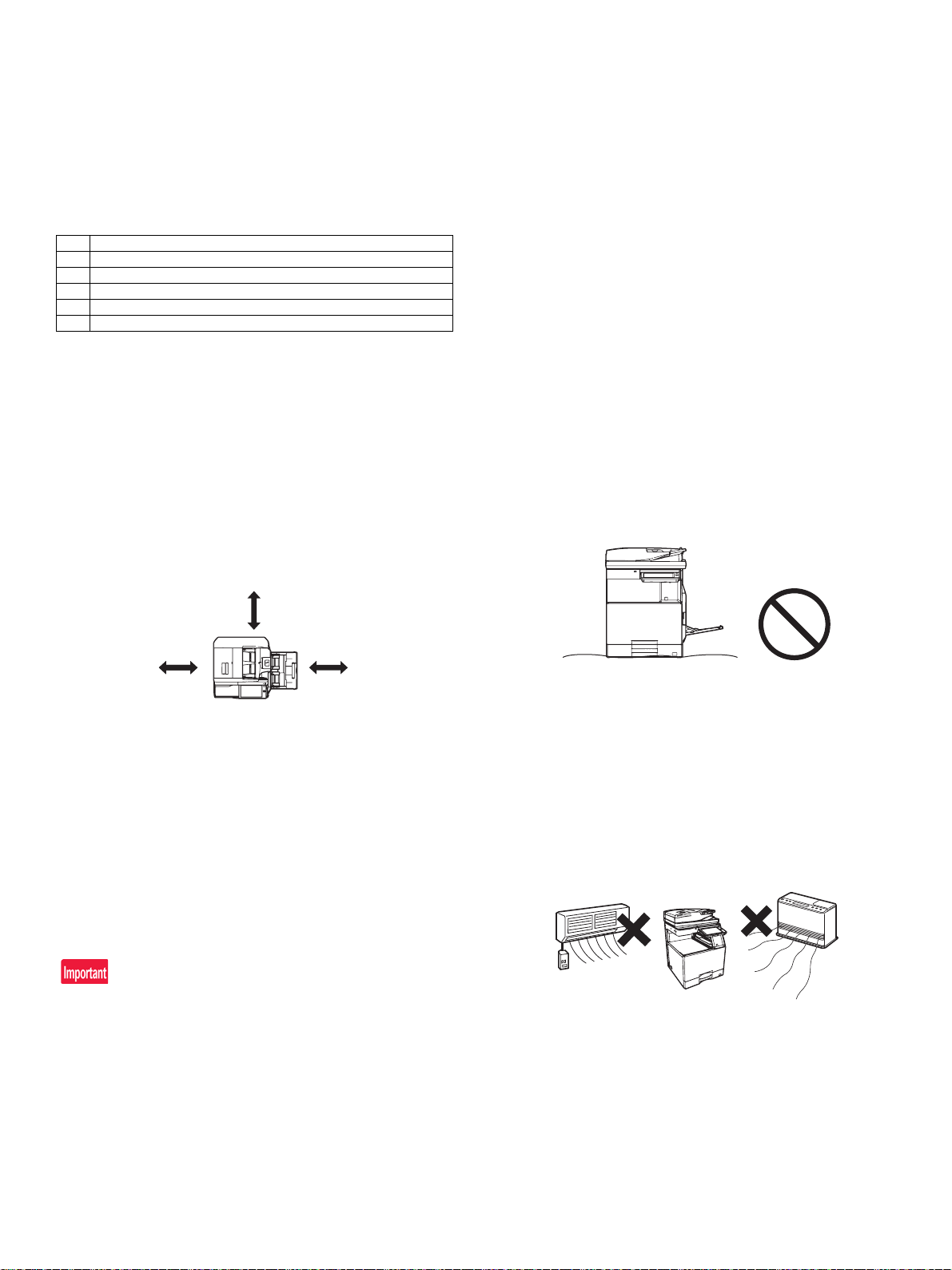
The following space must be provided around the machine in order to
assure machine performances and proper operations.
If any option is installed, provide the additional space for installing it.
Adequate space must be provide behind the machine for proper venti-
lation heat and dust. If not, the machine cannot exhibit functions
against heat and dust, causing some troubles.
Power frequency, waveform
The frequency must be within the range of the specified frequency
2%. If power waveform is deformed, a trouble may occur.
Safety
Be sure to properly ground the machine.
Grounding (earth connection) must be performed before inserting the
power plug into the power outlet.
When disconnecting the earth connection, be sure to disconnect the
power plug from the power outlet in advance.
Power plug
Check the shape of the power plug of the machine, and insert it into a
power outlet of the acceptable shape.
Power plug stated in power capacity.
D. Floor strength and level
This machine is considerably heavy and becomes heavier with an
option installed.
The floor must be strong enough to safely support the weight of the
machine as well as any installed options.
If the unit is not horizontally installed, the toner density control is not
performed normally, degrading the copy quality.
If not, color shift or image distortion may occur.
To assure proper Image quality, make sure the machine is setting
level.
C. Power source (Capacity, voltage, frequency,
safety, plug)
If the power specifications are not satisfied, the machine cannot exhibit
full performances and may cause safety trouble.
Strictly observe the following specifications.
Power capacity
Check that the following power capacity is satisfied. If not, additionally
provide a power source.
Current capacity
Japan: 20A or more
EX 100V: 15A or more
EX 200V: 10A or more
Check the shape of the power plug of the machine, and insert it into a
power outlet of the acceptable shape.
Power voltage
Measure the voltage during copying to check that the voltage is in the
range of the specified voltage 10%.
If the voltage is outside the specified range, please have a certified
electrician upgrade the outlet.
(An electrical work is required.)
Use of a step-up transformer is also available. In this case, the capac-
ity must be great enough for the max. power consumption of the
machine.
E. Direct rays of the sun, dust, temperature,
humidity, gasses, chemicals, vibration
Temperature and humidity (Environmental conditions)
This machine is designed to perform properly under the specified temperature and humidity. If the temperature and humidity exceeds the
specified range, the machine may not operate properly and or cause
equipment failure.
Especially when the humidity is too high, paper absorbs humidity to
cause a paper jam or dirty copy.
Do not install the machine near a heater, a cooler, or a humidifier.
Condensation may form inside the machine causing multiple troubles.
Use enough care for ventilation.
MX-4070N Transit, Installation (using) environment, Note – i
Page 5

Operational environment
85%
Humidity㸦RH㸧
60%
20%
Temperature: 10 to 35C
Humidity: 20 to 85% RH
Atmospheric pressure: 590 to 1013hPa (altitude: 0 to 2000 m)
Contaminates
If dust enters the machine, it may cause dirty copy and a paper jam,
resulting in a shortened lifetime.
F. Note for handling PWB and electronic parts
When handling the PWB and the electronic parts, be sure to observe
the following precautions in order to prevent against damage by static
electricity.
• When in transit or storing, put the parts in an anti-static bag or an
anti-static case and do not touch them with bare hands.
• When and after removing the parts from an anti-static bag (case),
use an earth band as shown below:
• Put an earth band to your arm, and connect it to the machine.
Direct sunlight
If the machine is installed under the rays of the sun, the exterior of the
machine may be discolored and abnormal copies may be produced.
Gases and chemicals
Do not install the machine at a place where there are gases and chemicals. Especially be careful to avoid installation near a diazo-type
copier, which produces ammonium gas.
Copy quality may be adversely affected and a trouble may be caused.
Vibration
Avoid installation near a machine which produces vibrations.
If vibrations are applied to the copier machine, copy images may be
deflected and a trouble may be caused.
• When repairing or replacing an electronic part, perform the proce-
dure on an anti-static mat.
MX-4070N Transit, Installation (using) environment, Note – ii
Page 6

G. Note for proper drum, developing, fusing and
transfer unit handling
When handling the OPC drum, developing and transfer units, observe
the following items.
Drum unit
• To prevent damage to the OPC drum, avoid working on the drum
unit in high intensity light areas.
• When the OPC drum is removed from the machine, cover it with
light blocking material. (When using paper, use about 10 sheets of
paper to cover it.)
• Be careful not to attach fingerprints, oil, grease, or other foreign
material on the OPC drum surface.
Transfer unit
• Be careful not to "leave” fingerprints, oil, grease, or other foreign
material on the transfer roller, primary transfer belt and secondary
transfer roller.
Developing unit
• Be careful not to "leave” fingerprints, oil, grease, or other foreign
material on the developing unit.
Fusing unit
• Be careful not to "leave” fingerprints, oil, grease, or other foreign
material on the fusing roller and the external heating belt.
• Do not leave the fusing roller in contact state for a long time.
If these items are neglected, a trouble may be generated in the copy
and print image quality.
2. Transit and delivery
No. Content Method
1 Implements, facility,
and man power
2 Delivery Transit must be made in packed condition.
Use a forklift. (If no forklift is available,
manpower of two persons is required.)
A. Implements, facility, and manpower
It is recommendable to use a forklift for bringing in the machine for
safety.
If no forklift is available, man-power of two persons is required. The
machine is considerably heavy, and requires safety precautions for
delivery and installation.
Transit of the machine must be made in packed condition to the installing place.
Since the hard disk drive is built in the machine, use care not to exert
vibrations or shocks to the machine when in transit.
B. Delivery
Remove the packing materials prior to installation in the office environment.
3. Relationship between the model name and
the designation in description of the
document
Model name Designation in description
MX-3070N / MX-3060N / MX-3050N 30cpm machine
MX-3570N / MX-3560N / MX-3550N 35cpm machine
MX-4070N / MX-4060N / MX-4050N 40cpm machine
MX-4070N Transit, Installation (using) environment, Note – iii
Page 7
MX-3070N
MX-3570N
MX-4070N
DIGITAL FULL COLOR
MULTIFUNCTIONAL SYSTEM
MX-DE25
STAND/550 SHEET
PAPER DRAWER
MX-DE26
STAND/2x550 SHEET
PAPER DRAWER
MX-DE27
STAND/3x550 SHEET
PAPER DRAWER
MX-LC17
LARGE CAPACITY
TRAY
MX-LT10
LONG PAPER
FEEDING TRAY
MX-DE28
STAND/550&2100 SHEET
PAPER DRAWER
MX-TR19
EXIT TRAY UNIT
MX-TU16
EXIT TRAY CABINET
MX-RB25
PAPER PASS UNIT
MX-TR20
JOB SEPARATOR
TRAY
MX-FN29
SADDLE STITCH
FINISHER (1K)
MX-FN28
FINISHER (1K)
MX-FN30
FINISHER (3K)
MX-FN31
SADDLE STITCH
FINISHER (3K)
MX-FN27
INNER FINISHER
MX-PN15
B/C/D
PUNCH
MODULE
MX-PN14
B/C/D
PUNCH MODULE
MX-PN16
B/C/D
PUNCH
MODULE
MX-3050N
MX-3550N
MX-4050N
MX-3060N
MX-3560N
MX-4060N
DIGITAL FULL COLOR
MULTIFUNCTIONAL SYSTEM
MX-UT10
UTILITY TABLE
MX-DE29
LOW STAND/550
SHEET PAPER
MX-FWX1
INTERNET FAX
EXPANSION KIT
MX-AMX1
APPLICATION
INTEGRATION MODULE
MX-AMX2
APPLICATION
COMMUNICATION MODULE
MX-AMX3
EXTERNAL ACCOUNT
MODULE
MX-PF10
BARCODE FONT KIT
MX-FX15
FACSIMILE EXPANSION
KIT
AR-SU1
STAMP UNIT
MX-USX1
SHARPDESK 1 LICENSE
KIT
MX-USX5
SHARPDESK 5 LICENSE
KIT
MX-US10
SHARPDESK 10 LICENSE
KIT
MX-US50
SHARPDESK 50 LICENSE
KIT
MX-USA0
SHARPDESK 100 LICENSE
KIT
MX-PK13
PS3 EXPANSION KIT
MX-PU10
DIRECT PRINT EXPANSION
KIT
MX-EB11
ENHANCED COMPRESSION
KIT
MX-EB18
WIRELESS LAN ADAPTOR
MX-FR51U/FR52U
DATA SECURITY KIT
1
: ‘16/Feb.
1
MX-4070N
[1] CONFIGURATION
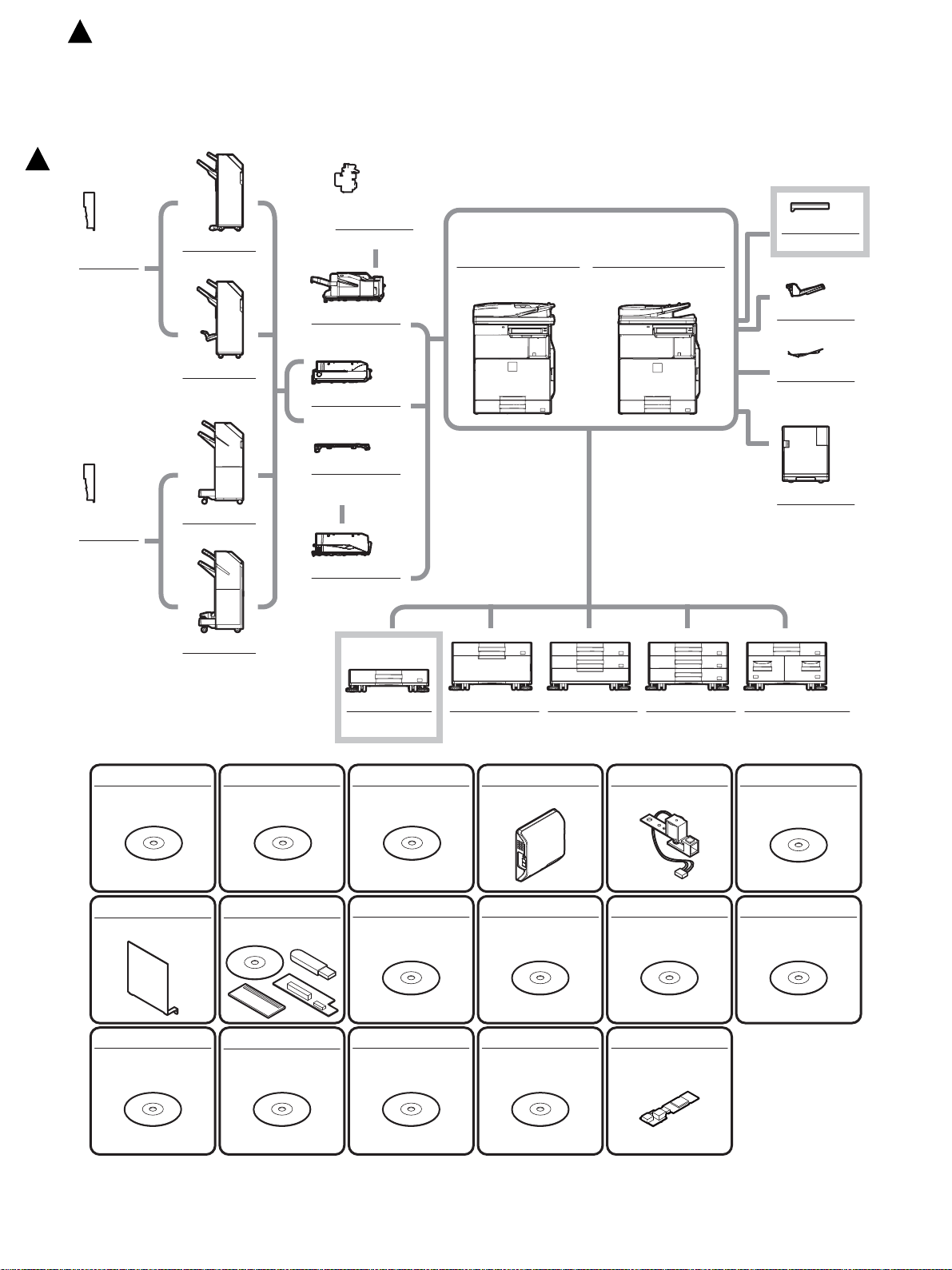
1. System diagram
Service Manual
MX-4070N CONFIGURATION 1 – 1
Page 8
: ‘16/Feb.
1
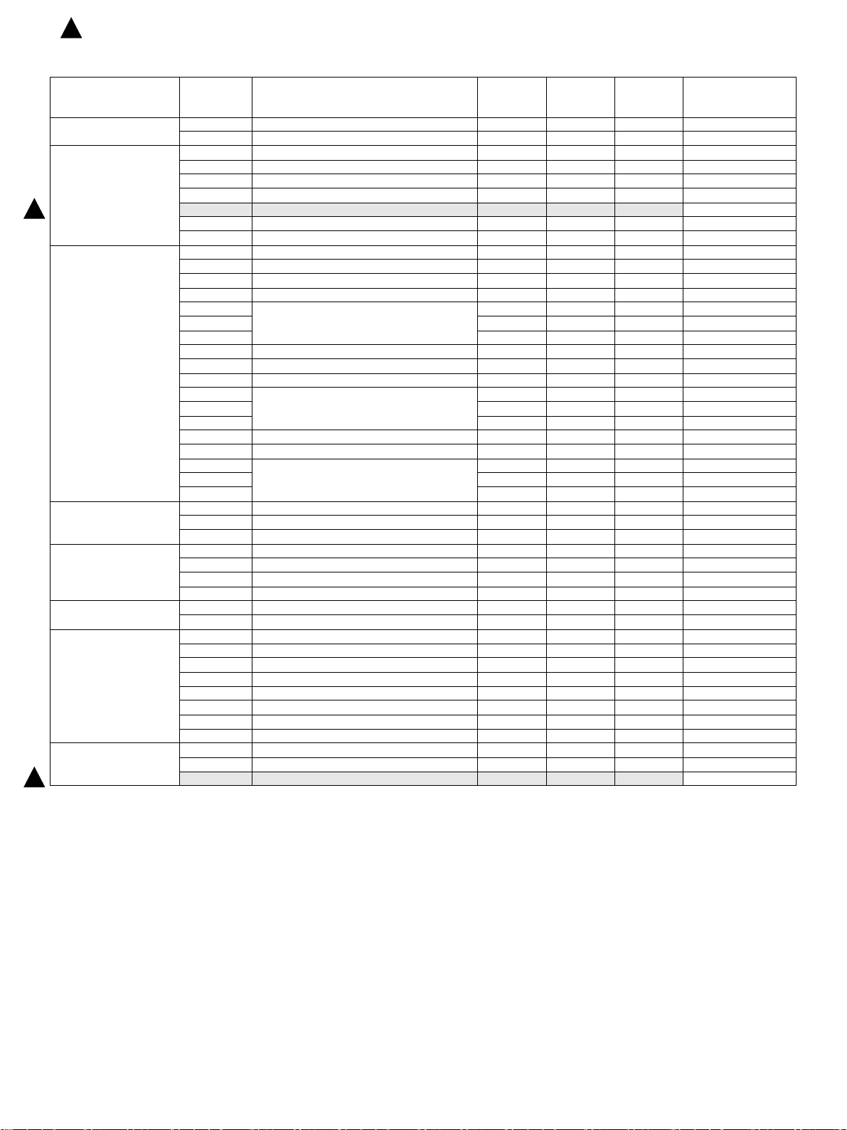
2. Option list
Model name Description
Document Feed System ― REVERSING SINGLE PASS FEEDER ― STD STD
― DUPREX SINGLE PASS FEEDER STD ――
Paper Feed System MX-DE25 STAND/550 SHEET PAPER DRAWER OPT OPT OPT
1
Paper Exit System MX-TR19 EXIT TRAY UNIT OPT OPT OPT
Printer Expansion MX-PK13 PS3 EXPANSION KIT STD OPT OPT
Image Send Expansion MX-FX15 FACSIMILE EXPANSION KIT OPT OPT OPT *2
Authentication / Security MX-FR51U DATA SECURITY KIT ――OPT
Application / Solution MX-USX1 SHARPDESK 1 LICENSE KIT OPT OPT OPT
Other MX-EB18 WIRELESS LAN ADAPTOR STD OPT OPT *2
1
MX-DE26 STAND/2x550 SHEET PAPER DRAWER OPT OPT OPT
MX-DE27 STAND/3x550 SHEET PAPER DRAWER OPT OPT OPT
MX-DE28 STAND/550&2100 SHEET PAPER DRAWER OPT OPT OPT
MX-DE29 LOW STAND/550 SHEET PAPER OPT OPT OPT
MX-LC17 LARGE CAPACITY TRAY OPT OPT OPT
MX-LT10 LONG PAPER FEEDING TRAY OPT OPT OPT
MX-TU16 EXIT TRAY CABINET STD/OPT STD/OPT STD/OPT *1
MX-TR20 JOB SEPARATOR TRAY OPT OPT OPT
MX-FN27 INNER FINISHER OPT OPT OPT
MX-PN14B PUNCH MODULE OPT OPT OPT For MX-FN27
MX-PN14C OPT OPT OPT
MX-PN14D OPT OPT OPT
MX-FN28 FINISHER (1K) OPT OPT OPT
MX-FN29 SADDLE STITCH FINISHER (1K) OPT OPT OPT
MX-RB25 PAPER PASS UNIT OPT OPT OPT
MX-PN15B PUNCH MODULE OPT OPT OPT For MX-FN28/FN29
MX-PN15C OPT OPT OPT
MX-PNX5D OPT OPT OPT
MX-FN30 FINISHER (3K) OPT OPT OPT
MX-FN31 SADDLE STITCH FINISHER (3K) OPT OPT OPT
MX-PN16B PUNCH MODULE OPT OPT OPT For MX-FN30/FN31
MX-PN16C OPT OPT OPT
MX-PN16D OPT OPT OPT
MX-PF10 BARCODE FONT KIT OPT OPT OPT
MX-PU10 DIRECT PRINT EXPANSION KIT STD OPT OPT
AR-SU1 STAMP UNIT OPT OPT OPT
MX-FWX1 INTERNET FAX EXPANSION KIT OPT OPT OPT
MX-EB11 ENHANCED COMPRESSION KIT STD STD OPT
MX-FR52U DATA SECURITY KIT OPT OPT ―
MX-USX5 SHARPDESK 5 LICENSE KIT OPT OPT OPT
MX-US10 SHARPDESK 10 LICENSE KIT OPT OPT OPT
MX-US50 SHARPDESK 50 LICENSE KIT OPT OPT OPT
MX-USA0 SHARPDESK 100 LICENSE KIT OPT OPT OPT
MX-AMX1 APPLICATION INTEGRATION MODULE OPT OPT OPT
MX-AMX2 APPLICATION COMMUNICATION MODULE STD/OPT OPT OPT *1
MX-AMX3 EXTERNAL ACCOUNT MODULE STD/OPT OPT OPT *1
― KEYBOARD STD ――*2
MX-UT10 UTILITY TABLE OPT OPT OPT
MX-3070N
MX-3570N
MX-4070N
MX-3060N
MX-3560N
MX-4060N
MX-3050N
MX-3550N
MX-4050N
STD: Standard equipment
OPT: Installable option
*1: Option in some area
*2: No support in some area
Remarks
MX-4070N CONFIGURATION 1 – 2
Page 9
ĭ
Į
į
Į
MX-4070N
[2] MX-3070N/3570N/4070N/3060N/3560N/4060N/3050N/3550N/4050N
Service Manual
(MAIN UNIT)
1. For enclosed developer shipment (From April 2016 production)
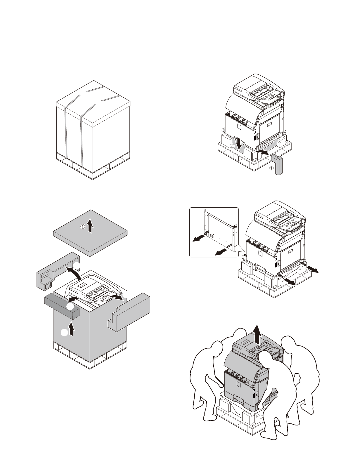
A. Unpacking
1) Cut the polypropylene bands.
3) Remove F -add. Remove the vinyl bag of the main unit.
2) Remove the top case, cushioning materials, and case of the main
unit.
4) Pull out the grips.
5) Lift the main unit slowly by 4 people, and put it gently to the flat
and safety place.
MX-4070N 2 – 1
Page 10
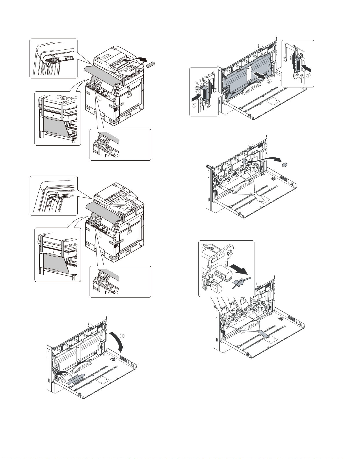
(1) Fixing tape and protection material removal
DSPF Model
EXIT TRAY
CABINET
standard
model
RSPF Model
EXIT TRAY
CABINET
standard
model
2) Remove the waste toner box toward you while pushing the
unlocking levers on both sides of the waste toner box.
3) Remove the transfer unit fixing material.
1) Open the cover and remove the silica gel.
4) Remove the DV sheet.
Insert the DV sheet when the machine will be moved.
MX-4070N 2 – 2
Page 11

Ĭ
Ĭ
ĭ
Ĭ
ĭ
ĭ
Ĭ
ĭ
ĭ
Ĭ
: ‘16/Sep.
3
[For North America from October 2016 production]
3
4-a) Turn the drum cover securing locks (2) to release, and then
raise the drum positioning cover.
4-b) Raise a lever to the left. Pull out the developing unit to
remove.
4-d) Insert the developing unit so as not to give a strong shock to
the main unit gently.Raise a lever to the right.
Slide the developing unit horizontally into the machine, in the
direction of the arrow, until developing unit locks into. place.
Do not push the unit diagonally, as cont act with the drum may
occur causing damage.
When removing or installing the developing unit, put your
hand from below the unit and slide it in parallel along the
guide.
At that time, be careful not to touch the roller surface.
4-c) Remove the fixing tape.
When installing the machine, there is no need to remove or
install the OPC drum unit. If it must be removed or installed
for any reason, follow the procedures below. When removing
or installing the OPC drum unit, put your hand from below the
unit and slide it in parallel along the guide on the right side.
At that time, be careful not to touch the OPC drum surface.
4-e) Close the drum positioning cover, and lock it.
MX-4070N 2 – 3
Page 12
Ĭ
2
1
Ĭ
ĭ
Į
: ‘16/Sep.
3
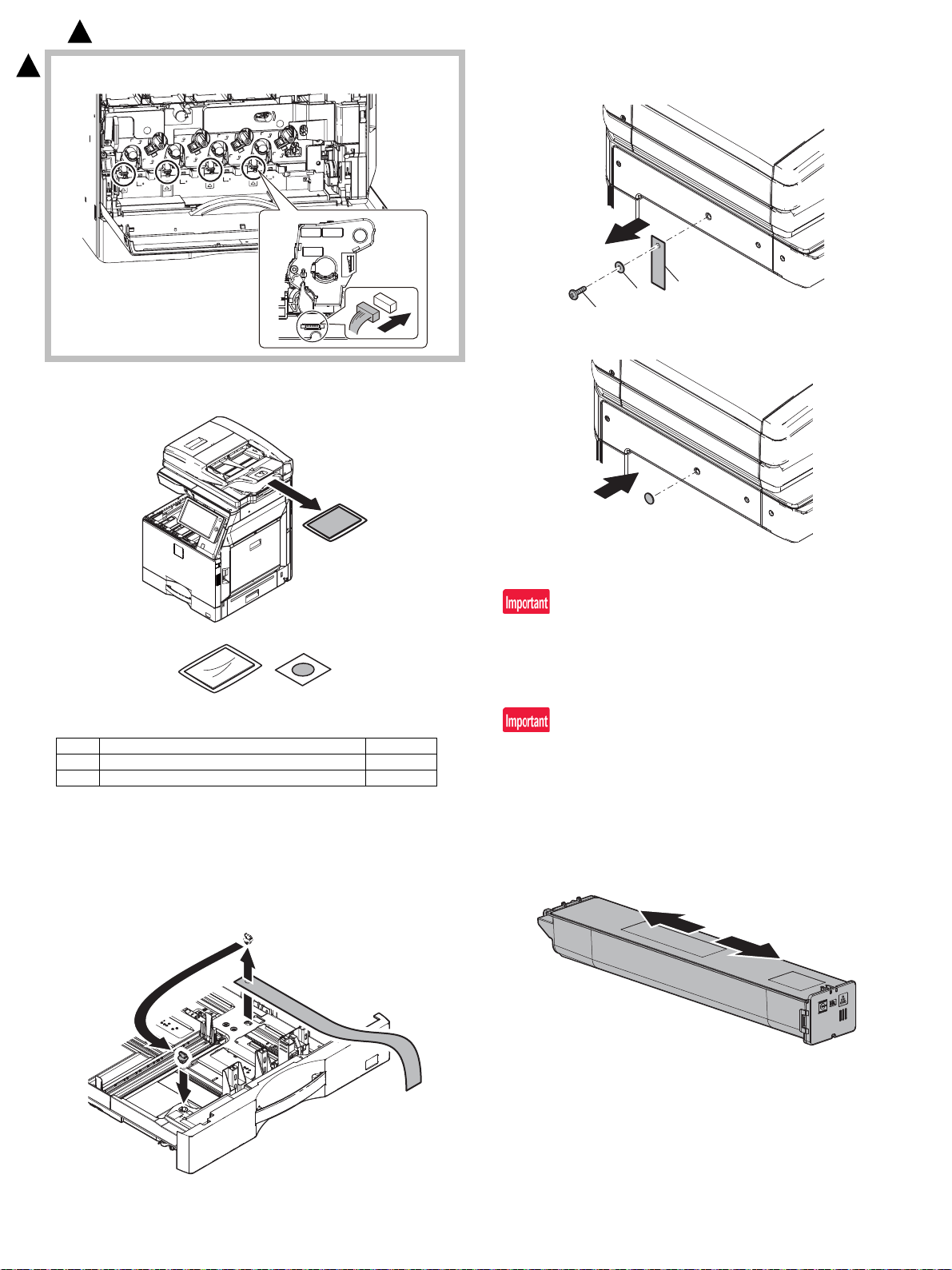
4-f) Connect the connecter.
3
(2) Packed items check
b. Scanner (2/3 mirror unit) lock release
1) Remove the optical unit fixing screw, and remove the note label.
2) Attache the protection sheet.
No. Name Quantity
1 Operation manual 1
2 Protection sheet 1
(3) Lock release
a. Tray rotation plate lock release
1) Pull out the tray. Turn the fixing material and remove it. Remove
the caution label.
Attach the removed fixing material to the position shown in the figure for future use.
Close the tray which was pulled out.
B. Installation
When an optional paper feed desk is connected to the machine,
unpack and install the paper feed desk, then unpack the machine.
Place the machine on the option desk securely, and perform the
installing procedures of the machine.
Place the machine on the optional desk firmly and secure.
This models have been shipped with developer enclosed into the
developer unit and done Sim25-2. Therefore do NOT execute Sim25-2
at machine installation.
If executed Sim25-2, replace all of the developers with new ones and
execute Sim25-2. If the machine have been used without replacing the
new developer. It may be trouble related to the life performance.
(1) Toner cartridge installation
1) Shake the toner cartridge horizontally several times
MX-4070N 2 – 4
Page 13

: ‘16/Sep.
3
2) Open the front cover and insert each toner cartridge
Be sure to install the color cartridge to their proper positions.
Avoid installation to a different color position.
Do not forcibly insert the toner cartridge.
Push it in until the cartridge is securely locked in place.
(2) Cleaning
a. Cleaning of LSU's dust-proof glass and PTC wire
Dust from the transfer belt or shutter or some other adjacent part may
fall onto the LSU during transport or installation. Be sure to clean the
dust-proof glass and PTC wire before checking the image quality.
3
1) Detach the LSU cleaning bar from the front cover.
Developing units removed, be sure to remove the toner cartridges
as well to prevent toner clogging.
Mounting location of the toner cartridge of each color
3) Close the front cover
4) Confirm that "Toner replacement in progress" is displayed and
wait until the display disappears (It takes 30 sec - 6 min)
This procedure is for checking the toner supply operation from the
toner cartridge to the DV unit. The operation time differs depending on the toner quantity in the toner cartridge, uneven distribution
of toner and the internal state of the toner cartridge.
Do not perform operations which interrupt the above operation
such as opening the front cover, entering the Sim mode and turning OFF/ON the power. If this precaution is ignored. Trouble
codes F2-40 - 43 or F2-64 - 67 or a over-toned condition may
occur.
2) Turn the felt side of the cleaning bar downward and insert it. Slide
it back and forth a few times to clean the LSU dust-proof glass.
3) Return the LSU cleaning rod to the front cabinet so that the felt
faces upward. Fit the boss, and fix it with three pawls.
When the main unit is transported after the installation, be sure to
remove the DV unit and the Toner cartridge.
Then, be careful not to make the developer spilled out from the
mouth of the DV unit.
MX-4070N 2 – 5
Page 14
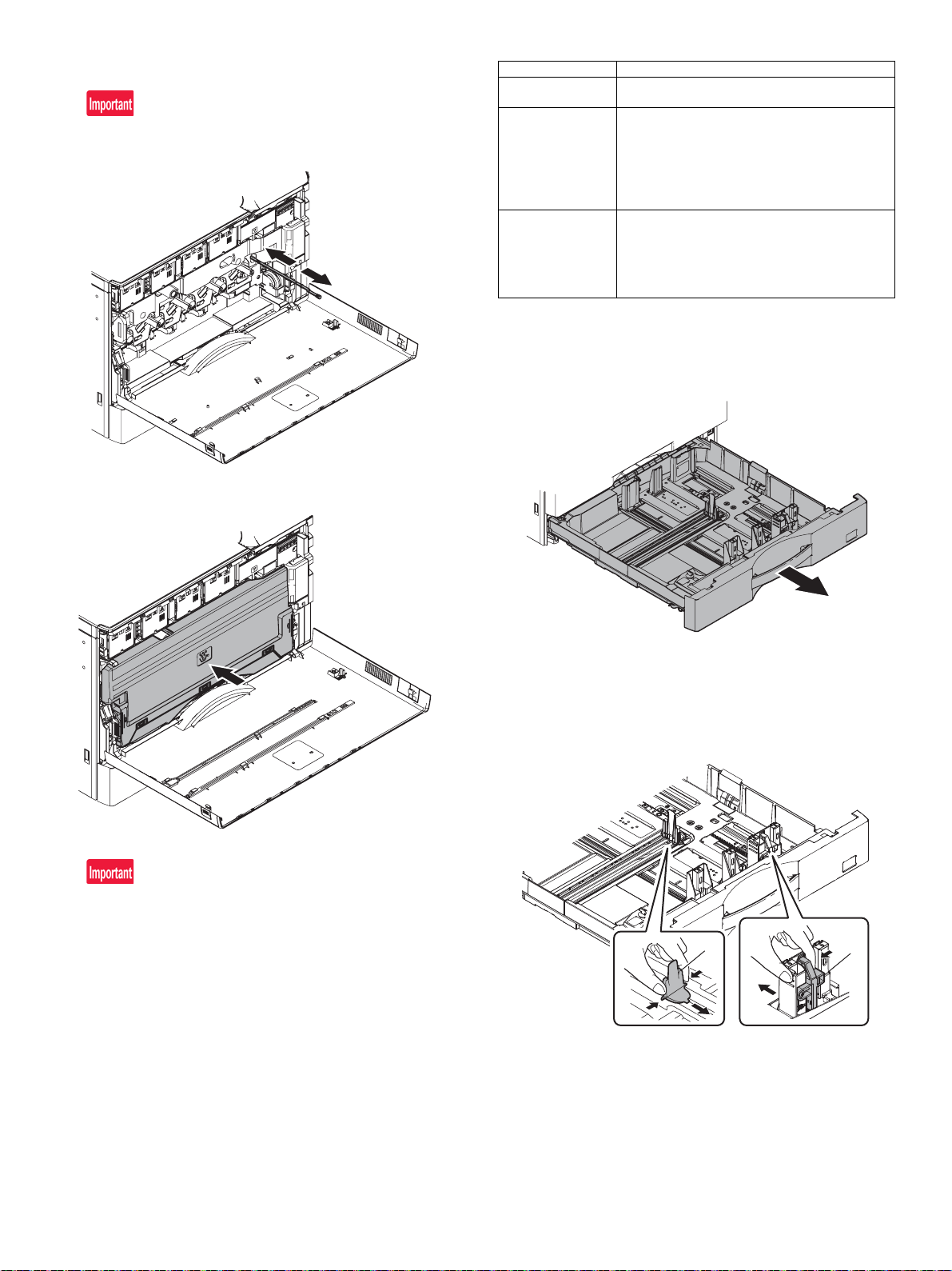
4) Move the PTC cleaning rod back and forth a few times to clean
A
B
the PTC wire.
After completion of cleaning, insert the cleaning rod completely to
the bottom.
5) Attach the waste toner box.
Both ends being locked surely.
Item Description
Type Select the type of p ape r t hat is lo aded in the tr ay. The
Size Select the paper size from the list. The paper sizes
Feeding Approved
Job
paper types that can be selected vary by paper tray.
that can be selected vary by tray. The sizes that can
be selected may also be restricted by the paper type
selected above.
If the desired size does not appear in the list, select
[Custom Size] and directly enter the size (only for the
bypass tray).
Select the modes that can be used. If there is a
function that you do not wish to be used with the
selected tray, disable the funct ion. When the "Type" is
other than plain paper, recycled paper , co lored p aper,
or a user type, [Fax] and [Internet Fax] cannot be
selected.
b. Tray size setup
1) Pull out the paper tray.
Gently pull the tray out until it stops.
If paper remains in the tray, remove it.
6) Close the front cover.
For the destination EXIT TRAY CABINET option.
Finisher or exit tray cabinet have to be installed before turning on
the machine otherwise get L4-11 code will occur.
(3) Paper feed tray setup
a. System setting
1) Press the [SETTINGS] key.
2) Touch the [Init. Install Settings] key.
3) Touch the [Password] key at the Administrator Login.
Enter the password with 10-key. "admin"
4) Touch the [Paper Tray Settings] key to configure the settings.
These settings specify the paper type, paper size, and functions
allowed for each paper tray. When the [Tray Settings] key is
touched, a list appears showing the trays and the current settings.
5) Touch the [Each tray] key in the above screen to change the settings. The following settings can be configured.
2) Adjust the guide plates A and B by squeezing their lock levers and
sliding them to match the vertical and horizontal dimensions of the
paper to be loaded.
The guide plates A and B are slidable. Slide each guide plate
while squeezing its lock lever.
MX-4070N 2 – 6
Page 15
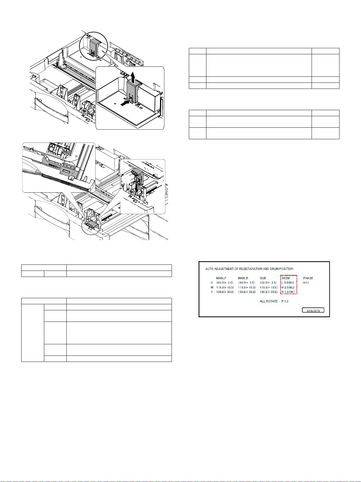
3) Adjust the guide plates A and B by squeezing their lock levers and
Ĭ
ĭ
Į
(4) Specifications setup
Use simulation 26-6 to set the machines destination.
C. Image quality check
(1) Execution items
Execute the following items.
No. Item SIM
1 Print engine image distortion adjustment (Manual
adjustment) / OPC drum phase adjustment
(Automatic adjustment) / Color registration adjustment
(Automatic adjustment)
2 Copy color balance and density check
3 Printer color balance/density check 64-5
When there are defects in a picture by the contents mentioned above,
you carry out the following contents, and confirm a picture.
No. Item SIM
4 Copy/Printer color balance adjustment (Automatic
adjustment)
5 Print/scan image off-center, lead edge position
adjustment
(2) Description
a. Print engine image di storti on ad just men t (Man ual adju stm ent)
/ OPC drum phase adjustment (Automatic adjustment) / Co lor
registration adjustment (Automatic adjustment)
This adjustment performs the print engine image distortion adjustment,
the OPC drum phase adjustment, and the color registration adjustment simultaneously.
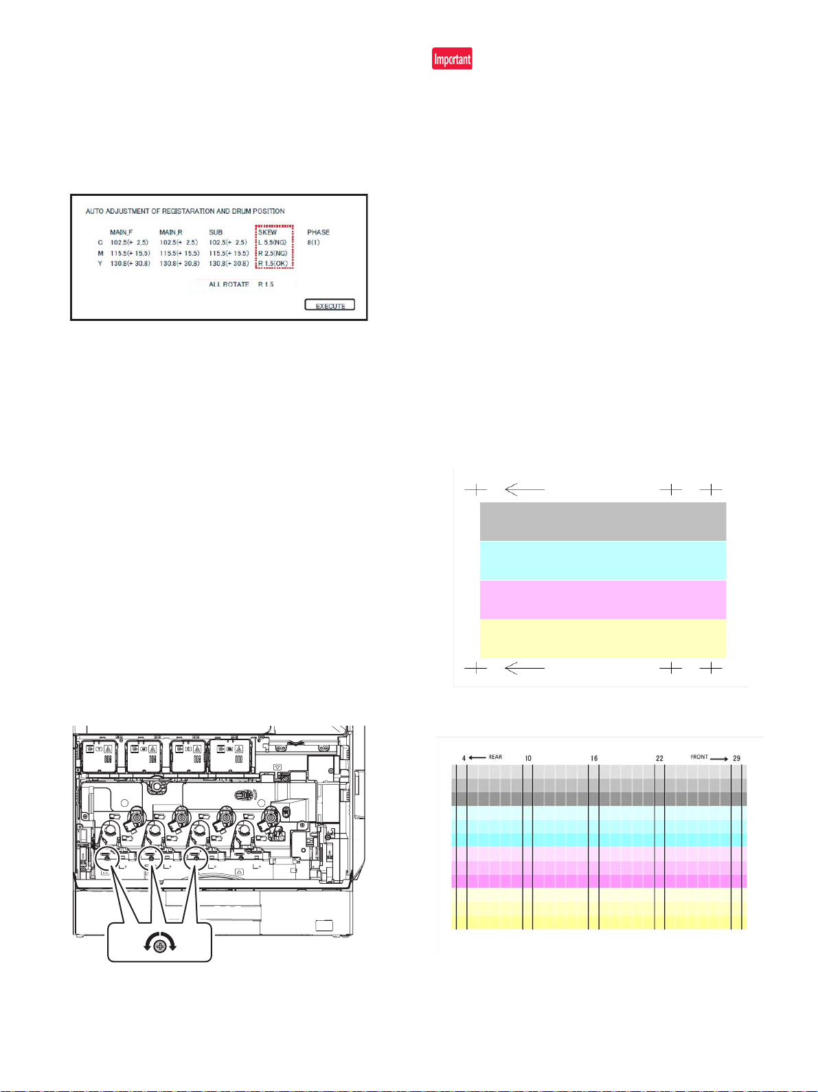
1) Enter SIM50-22 mode.
2) Press [EXECUTE] key.
[EXECUTE] key is highlighted and the image registration auto-
matic adjustment is started. (It takes about 30 sec to complete the
adjustment.)
3) When the adjustment is completed, [EXECUTE] key returns to the
normal display, and the value of the adjustment result is displayed.
The current skew level for each color is displayed on the SKEW
display section.
50-22
46-74
50-10
SIM No Content
26 6 Used to set the destination.
After completion of destination settings, change the set values to customize the following settings.
SIM No Content
26 3 Used to set the auditor specification mode.
5 Used to set the count mode of the total counter an d
the maintenance counter.
18 Used to set YES/NO of the toner save mode (Onl y in
UK and Japan versions)
* For other destination versions, this setup is made
by the user program.
52 Used to set YES/NO of counting when non-print
paper is passed through each counter.
65 Used to set the limit number of sheets for stapling.
MX-4070N 2 – 7
4) Write down the displayed skew level.
(Meaning of the skew level value and the adjustment procedure)
* If "OK" is displayed for all items of SKEW C,
M, and Y, there is no need to perform the adjustment.
* When "R" is displayed at the head of the value, turn the LSU
skew adjustment screw clockwise.
* When "L" is displayed at the head of the value, turn the LSU
skew adjustment screw counterclockwise.
* The turning amount of the adjustment screw corresponds to
each adjustment value. C, M, and Y indicate numbers of clicks.
The display value is rounded at the decimal point.
* "C, M, and Y(SKEW)" shows the number of adjustment click
steps for each adjustment screw of C, M, and Y.
Contents in ( )
MIAN, SUB: Difference from the previous adjustment value of
image registration.
Example:
If 105 for this time and 103 for the previous time,
it is displayed as 105.0 (+2.0).
SKEW: Judgment of the LSU skew adjustment result. OK or NG.
PHASE: OPC drum phase adjustment value of the previous time
Page 16
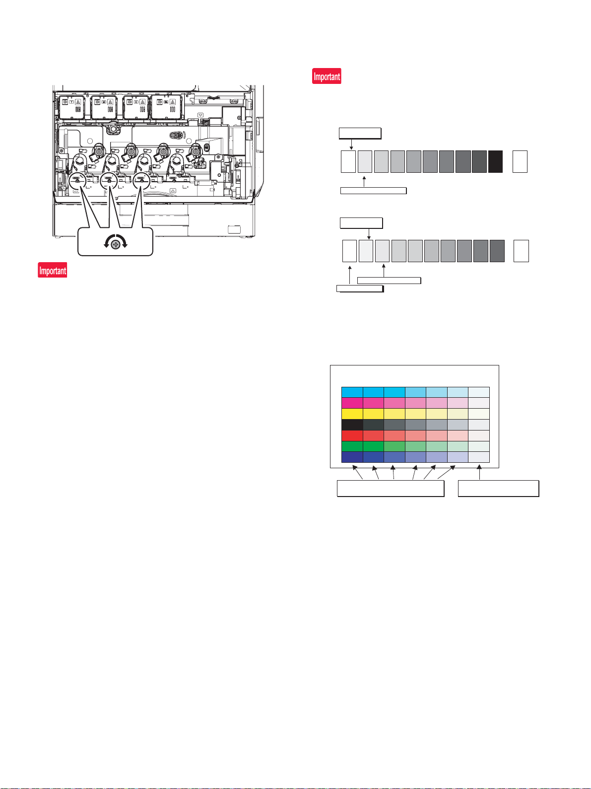
5) The procedures 2) to 4) again, and check to confirm that C, M,
12345678910 W
SHARP GRAY CHART
SHARP gray chart
Patch 1 is
slightly copied.
Patch 2 is copied.
(Color copy)
12345678910 W
SHARP GRAY CHART
SHARP gray chart
Patch 1 is not copied.
Patch 2 is
slightly copied.
Patch 3 is copied.
(Black-and-white copy)
Serviceman chart (Color patch section)
The densities of patches 1 - 6 of
each color are properly balanced.
Patch 7 is slightly
copied or not copied.
(Color copy)
and Y (SKEW) are OK.
If any of them is NG, turn the LSU skew adjustment screw of the
corresponding color to adjust.
When the adjustment is made by turning the LSU skew adjustment
screw of K, the states of C, M and Y (SKEW) are changed. Execute
SIM50-22 to check to confirm that C, M, and Y (SKEW) are OK.
When an abnormality occurs, "ERROR" is displayed.
In this case, check each drive section and the process section.
b. Copy color balance and density check
Method
Make a copy of the gray test chart (UKOG-0162FCZZ) and a copy of
the servicing color test chart (UKOG-0326FCZZ/UKOG-0326FC11),
and check that they are proper.
a. Note for execution of the color balance and density check in the
color copy mode
To check the copy color balance and density, use the gray test chart
(UKOG-0162FCZZ) and the servicing color test chart (UKOG0326FCZZ/UKOG-0326FC11). Set the copy density level to "3" in
the Text/Printed Photo mode (Manual), and make a copy.
At that time, all the color balance adjustments in the user adjustment
mode must be set to the default (center).
In addition, be sure to use the specified paper for color.
b. Note for checking the monochrome copy mode density
To check the density, use the gray test chart (UKOG-0162FCZZ).
Set the copy density level to "Manual 3" in the Text/Pr inted Photo
mode (Manual).
In addition, all the color balance adjustments in the user adjustment
mode must be set to the default (center).
[Check with the gray test chart (UKOG-0162FCZZ)]
In the copy density check with the gray test chart, check to insure the
following conditions.
For the color (gray) balance, use the servicing color test chart (UKOG0326FCZZ/UKOG-0326FC11) to check.
[Check with the servicing color test chart (UKOG-0326FCZZ/UKOG0326FC11)]
In the copy color balance check with the servicing color test chart,
check to insure the following conditions.
MX-4070N 2 – 8
Page 17
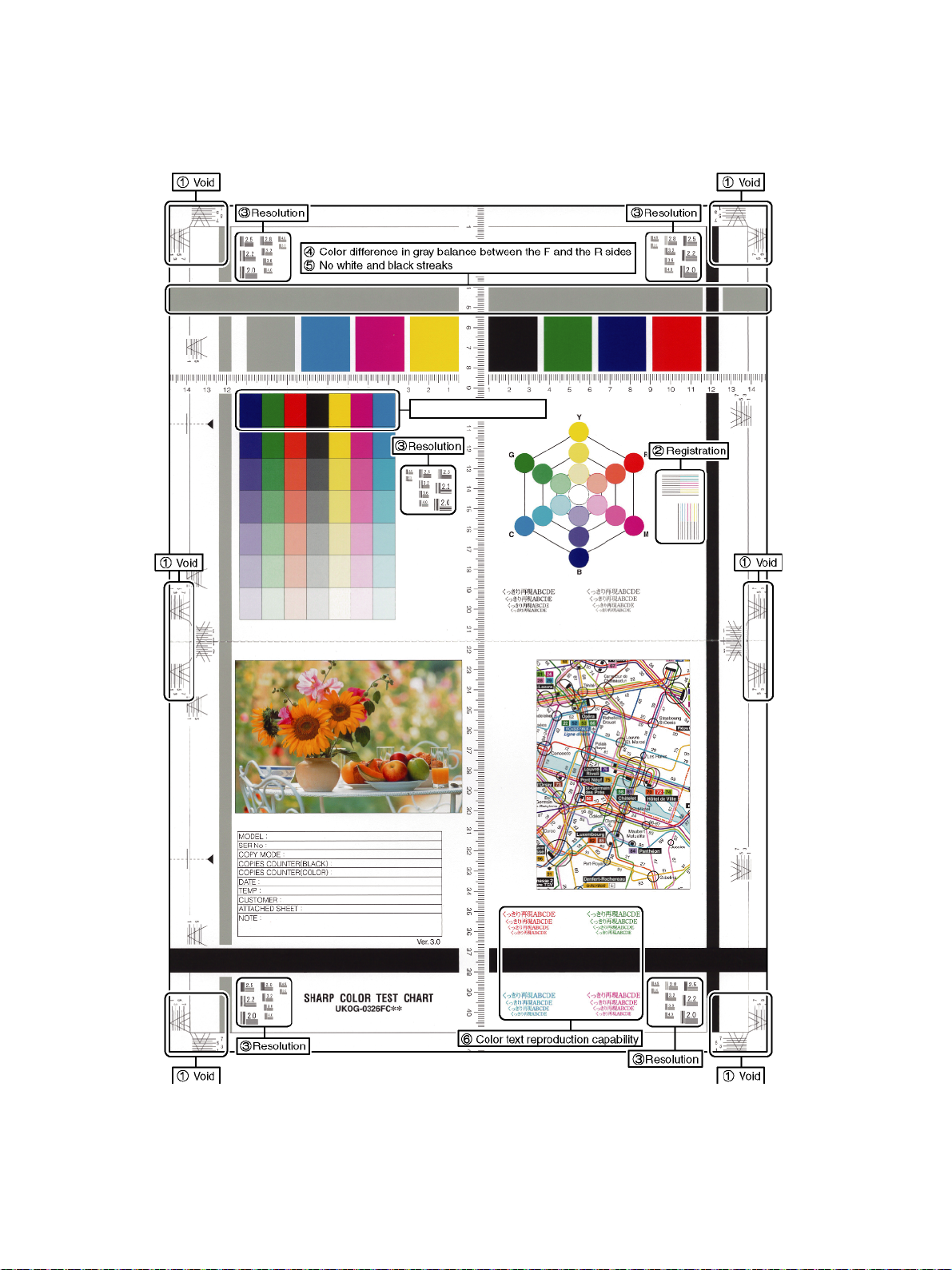
a. Color copy check items (Check to confirm the following:)
Solid density is not so light
IJ
1) There are 12 void areas.
2) Registrations (one point for the main scanning, and one point for
the sub scanning) are not shifted.
3) The resolution of 5.0 (5 points) can be seen.
4) The color difference in gray balance between the F and the R
sides is not so great.
5) There are no white and black streaks.
6) Color texts are clearly reproduced.
7) Solid density is not so light.
MX-4070N 2 – 9
Page 18
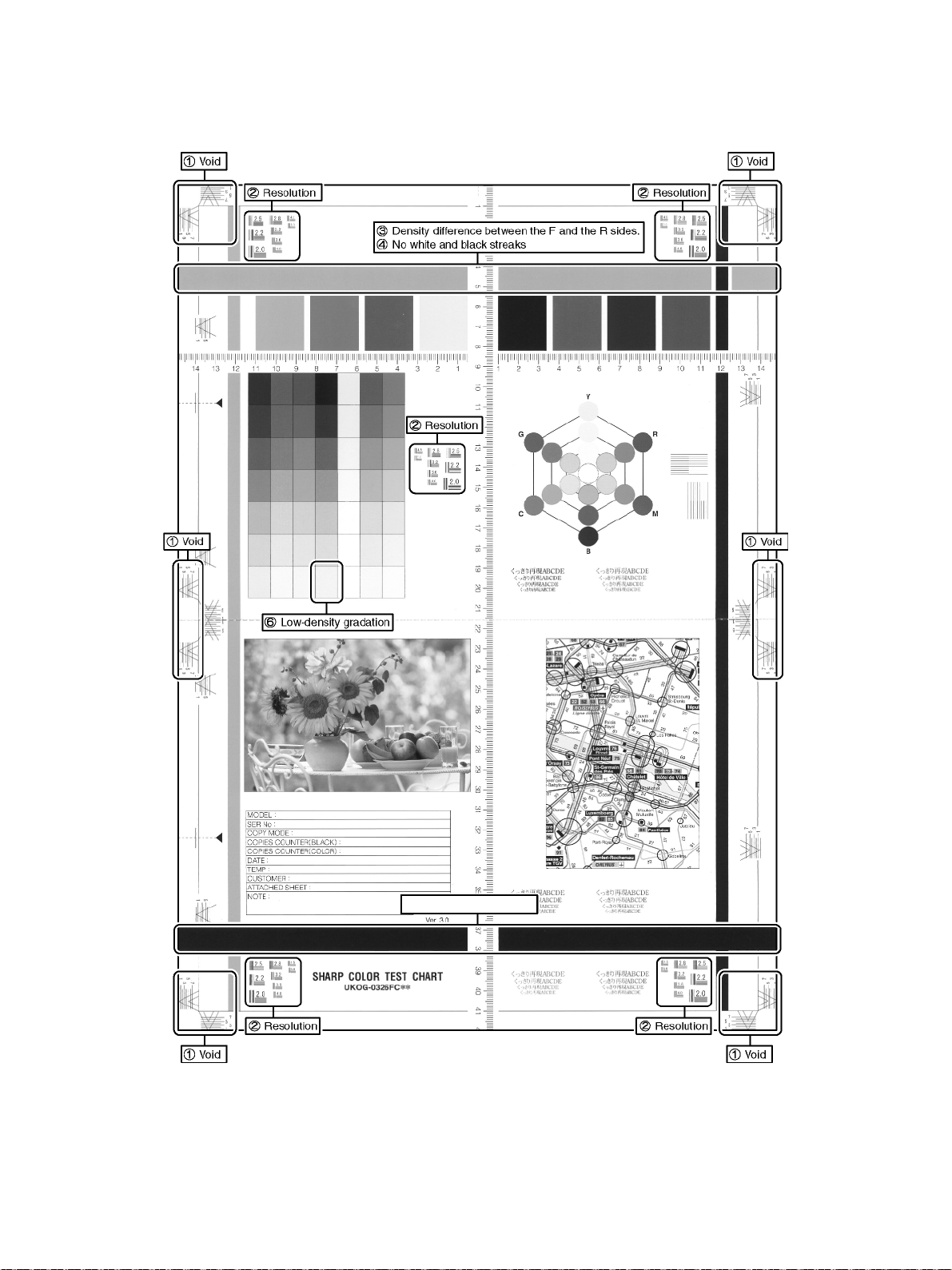
b. Monochrome copy check items (Check to confirm the following:)
Solid density is not so light
İ
1) There are 12 void areas.
2) The resolution of 4.0 (5 points) can be seen.
3) The density difference between the F and the R sides is not so
great.
4) There are no white and black streaks.
5) Solid density is not so light.
6) The black low-density gradation is copied slightly.
MX-4070N 2 – 10
Page 19
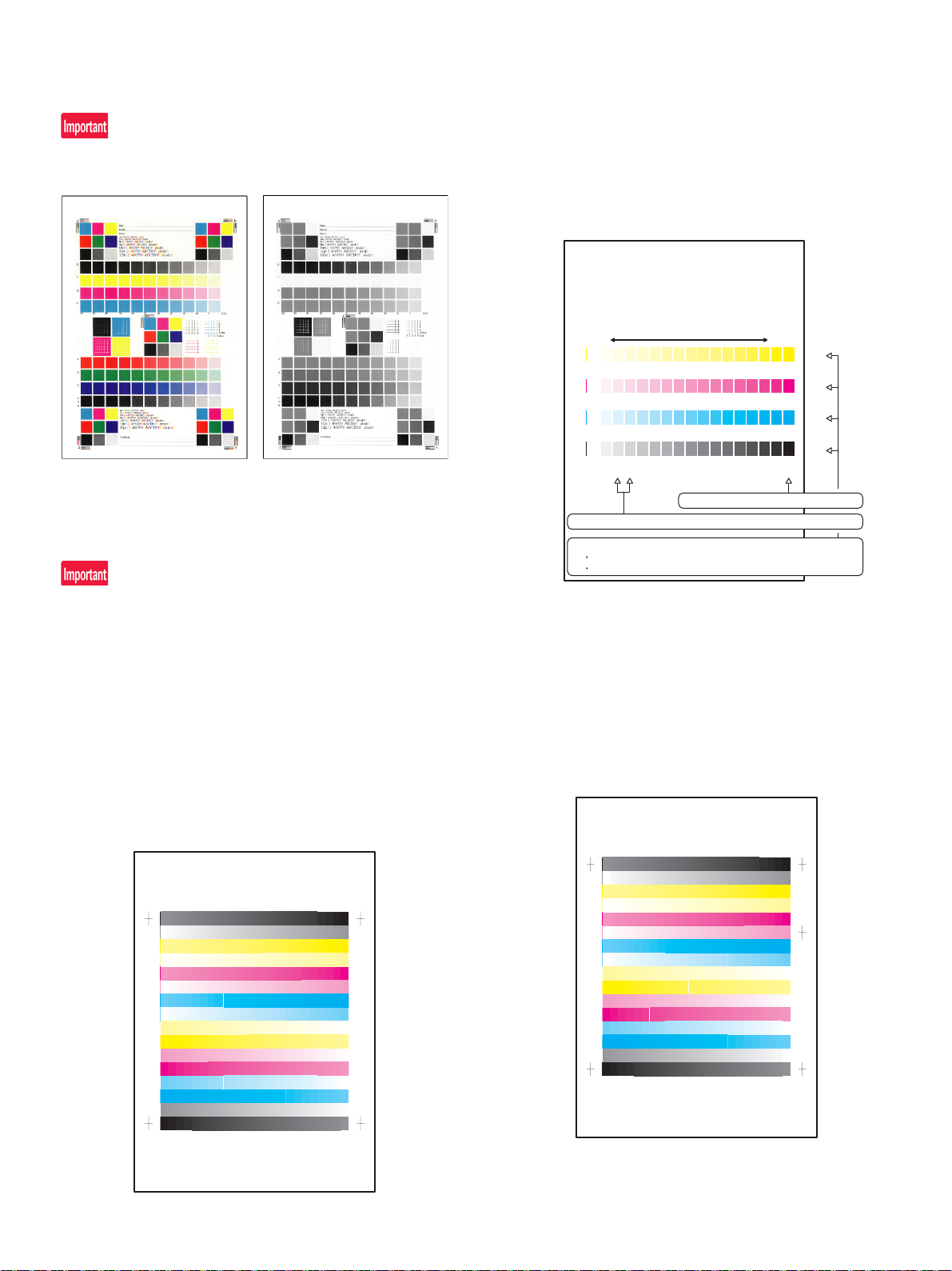
c. Printer color balance/density check
QOPNMLKJIHGFEDCBA
Y
M
C
Bk
High
density
Low
density
1) The max. density section is not blurred.
2) Patch C or D of each of Y, M, C, and BK is very slightly copied.
3) Patch for each of Y, M, C, BK
The patch density is identical between patches or not reversed.
The patch density is changed gradually.
PRINTER CALIBRATION
Method
Execute SIM 64-5 to print the print test pattern.
Set each set value to the default and press [EXECUTE] key. The print
test pattern is printed.
The print density must be changed gradually from the lighter level to
the darker level. The density changing direction must not be reversed.
The density level of each color must be almost at the same level.
d. Copy/Printer color balance and density adjus tment (Aut omat ic
adjustment)
4) Select [FACTORY] target, and press [EXECUTE] key.
When the color balance is customized by the manual color bal-
ance adjustment (SIM 46-21) according to the user's request, and
the color balance is registered with SIM63-7 as the service target,
if the color balance is required to be adjusted, select the [SERVICE] target.
The copy color balance adjustment is automatically executed and
prints the color balance check patch image.
If there is any streak or unclear print on the printed check pattern,
check the print engine for any problems.
When a printer option is installed, be sure to execute the above item.
1) Enter the SIM46-74 mode.
2) Press [EXECUTE] key.
The high density process control is performed, and the copy color
patch image (adjustment pattern) is printed out.
(A4/11" x 8.5" or A3/11" x 17" paper is automatically selected.)
3) Set the color patch image (adjustment pattern) paper printed in
procedure 2) on the document table.
Set the color patch image (adjustment pattern) printed in the procedure 2) on the document table. Place the color patch image so
that the fine lines are on the left side. At that time, place 5 sheets
of white paper on the printed color patch image (adjustment pattern).
5) Press [EXECUTE] key.
The printer color patch image (adjustment pattern) is printed out.
(A4/11" x 8.5" or A3/11" x 17" paper is automatically selected.)
6) Set the color patch image (adjustment pattern) printed in the procedure 5) on the document table.
Set the color patch image (adjustment pattern) printed in the procedure 2) on the document table. Place the color patch image so
that the fine lines are on the left side. At that time, place 5 sheets
of white paper on the printed color patch image (adjustment pattern).
MX-4070N 2 – 11
Page 20

7) Select [FACTORY] target, and press [EXECUTE] key.
PRINTER CALIBRATION
3120/.-,+*)('&%$#
;
/
%
$M
1) The max. density section is not blurred.
2) Patch C or D of each of Y, M, C, and BK is copied.
3) Patch for each of Y, M, C, BK
The patch density is identical between patches or not reversed.
The patch density is changed gradually.
High densityLow density
• Lead edge void amount
(4.0mm terget)
Measure at the center of
paper.
Adjustment value
J : SUB-CS
Print
lead edge
Main scanning magnification ratio (240 0.5mm)
Measure the dimension near the inner frame line
and the paper lead edge in parallel with the line.
Adjustment value A : BK-MAG
• F side void amount (2.0mm terget)
Measure at a position near the
paper lead edge.
Adjustment value
C : MAIN-CS1
When the color balance is customized with the manual color balance adjustment (SIM 67-25) according to the user's request and
the color balance is registered as the service target with SIM 6727, if the color balance is adjusted to that color balance, select the
[SERVICE] target.
The printer color balance adjustment (step 1) is automatically performed and the color balance check patch image is printed out.
If there is any streak or unclear print on the printed check pattern,
check the print engine for any problems.
e. Print/scan image off-center, lead edge position adjustment
Before executing this adjustment, be sure to check the fo llowing
items.
* There must be a tray with A4 (LT) paper in it.
1) Enter the Sim. 50-10 mode.
2) Select a paper feed tray 1.
3) Set A4 (11 X 8.5) paper on the paper feed tray 1.
4) Check to confirm that the inside dimension of the printed half-tone
pattern is 2400.5mm.
5) Measure the void area size of the adjustment pattern in the front/
rear frame direction (F side void amount) and that in the transport
direction (Lead edge void amount).
Check to confirm that all the following conditions are satisfied.
8) The initial setting menu of the half-tone image correction is displayed. Press [OK] key.
The initial setting of the half-tone image correction is performed.
9) Wait until [EXECUTE] key is displayed. When it is displayed,
press it.
The half-tone image correction is performed.
10) When "COMPLETED THIS PROCEDURE" is displayed, the
adjustment operation is completed.
Cancel SIM46-74.
The adjustment result becomes valid only when the both adjustments in the copy mode and in the printer mode are completed.
For example, if the copy color balance adjustment (automatic
adjustment) is performed and the simulation is canceled, the
adjustment result is invalid.
11) Check the copy color balance and density.
(Refer to the item of the copy color balance and density check.)
12) Check the printer color balance and density.
(Refer to the item of the printer color balance and density check.)
If the color balance or density is not in the satisfactory level even after
execution of the automatic and manual adjustments, there may be
another cause.
Troubleshoot the cause, repair or perform necessary works, and
repeat the adjustment from the beginning.
If color balance or density is not satisfied, adjust the copy and printer
color balance by SIM 46-74.
Calculation and input procedures of adjustment values
(Example) Lead edge void amount
(1) Measure by visual inspection.
Measurement result: 4.5mm
(2) Calculate the shift amount.
The target value is the specification value (center value) of
3mm.
* For the F side void amount, the target is 2mm.
[4 – 4.5 = -0.5 (mm)]
(3) Calculate the adjustment value.
Subtract 5 from the shift amount of -0.5mm.
* For the shift amount of 0.1mm, the adjustment value is
varied by 1.
When the current value is 50:
[50 – 5 = 45]
(4) Enter the adjustment value for SUB-CS.
Enter the [45].
6) Enter MAIN-CS1 (F side void) and SUB-CS (Lead edge void), and
press OK button.
Enter the calculated adjustment values for the shift amount to
MAIN-CS1/SUB-CS, and press OK button. (The cursor can be
used instead of the button.)
7) After entering the adjustment values, print again and check to
confirm that the avoid amounts are adjusted to the target range.
MX-4070N 2 – 12
Page 21
2. For bundled developer (bag) shipment
ĭ
Į
į
Į
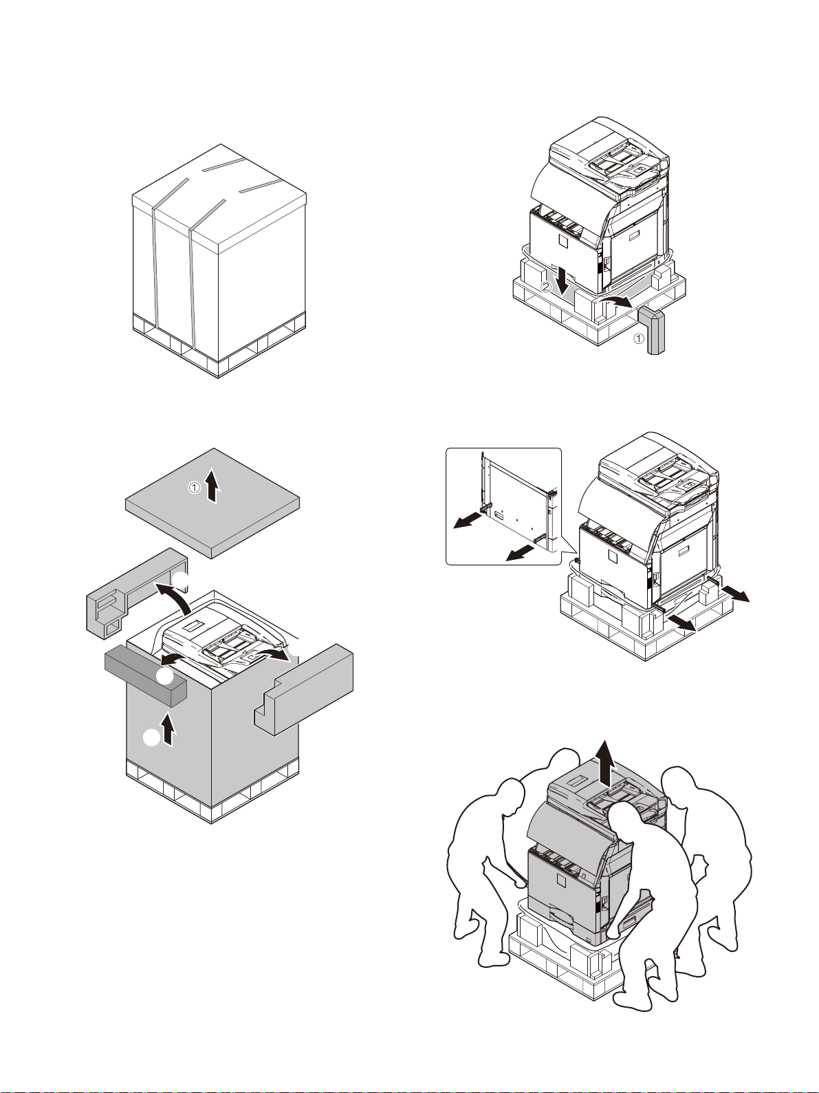
A. Unpacking
(1) Unpacking
1) Cut the polypropylene bands.
3) Remove F -add. Remove the vinyl bag of the main unit.
2) Remove the top case, cushioning materials, and case of the main
unit.
4) Pull out the grips.
5) Lift the main unit slowly by 4 people, and put it gently to the flat
and safety place.
MX-4070N 2 – 13
Page 22
DSPF Model
EXIT TRAY
CABINET
standard
model
RSPF Model
EXIT TRAY
CABINET
standard
model
1
4
3
2
: ‘16/Apr.
2
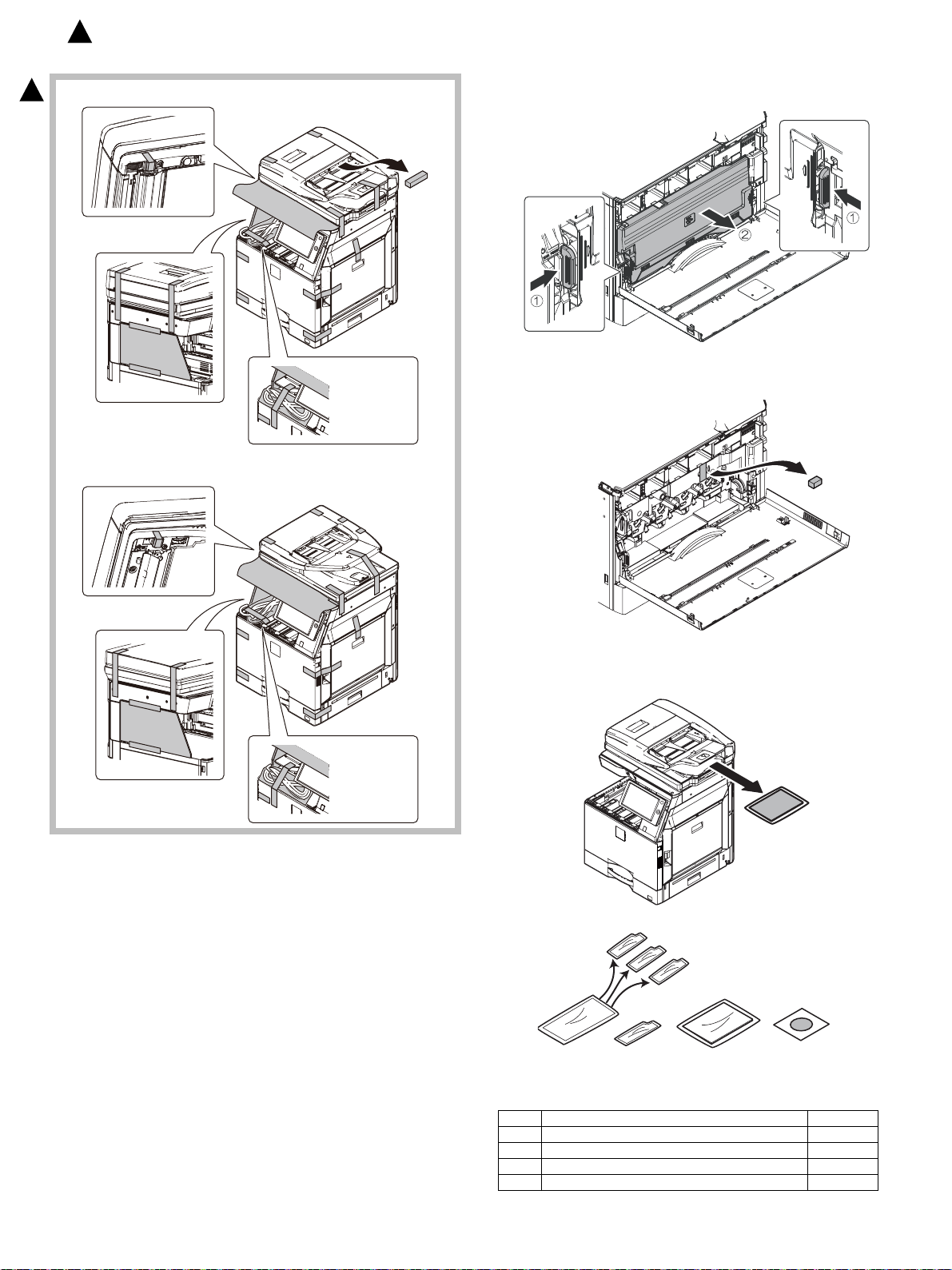
(2) Fixing tape and protection material removal
2
1) Remove the waste toner box toward you while pushing the
unlocking levers on both sides of the waste toner box.
2) Remove the transfer unit fixing material.
(3) Packed items check
No. Name Quantity
1 Developer (Color : C/M/Y) 1
2 Developer (Black) 1
3 Operation manual 1
MX-4070N 2 – 14
4 Protection sheet 1
Page 23
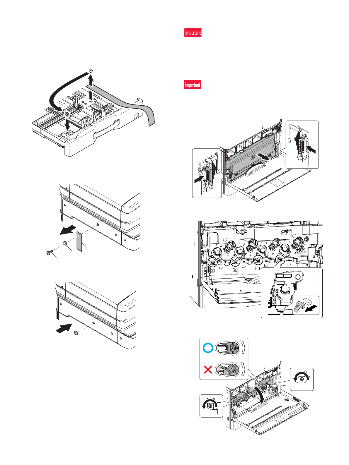
(4) Lock release
Ĭ
ĭ
Į
Ĭ
Ĭ
ĭ
Ĭ
Ĭ
Ĭ
ĭ
a. Tray rotation plate lock release
1) Pull out the tray. Turn the fixing material and remove it. Remove
the caution label.
Attach the removed fixing material to the position shown in the figure for future use.
Close the tray which was pulled out.
b. Scanner (2/3 mirror unit) lock release
1) Remove the optical unit fixing screw, and remove the note label.
B. Installation
When an optional paper feed desk is connected to the machine,
unpack and install the paper feed desk, then unpack the machine.
Place the machine on the option desk securely, and perform the
installing procedures of the machine.
Place the machine on the optional desk firmly and secure.
(1) Developer installation
Be careful not to leave fingerprints or oily dirt on the DV roller surface.
1) Open the front cabinet. Remove the waste toner box toward you
while pushing the unlocking levers on both sides of the waste
toner box.
2) Attache the protection sheet.
2) Remove the connecter.
3) Turn the drum cover securing locks (2) to release, and then raise
the drum positioning cover.
MX-4070N 2 – 15
Page 24
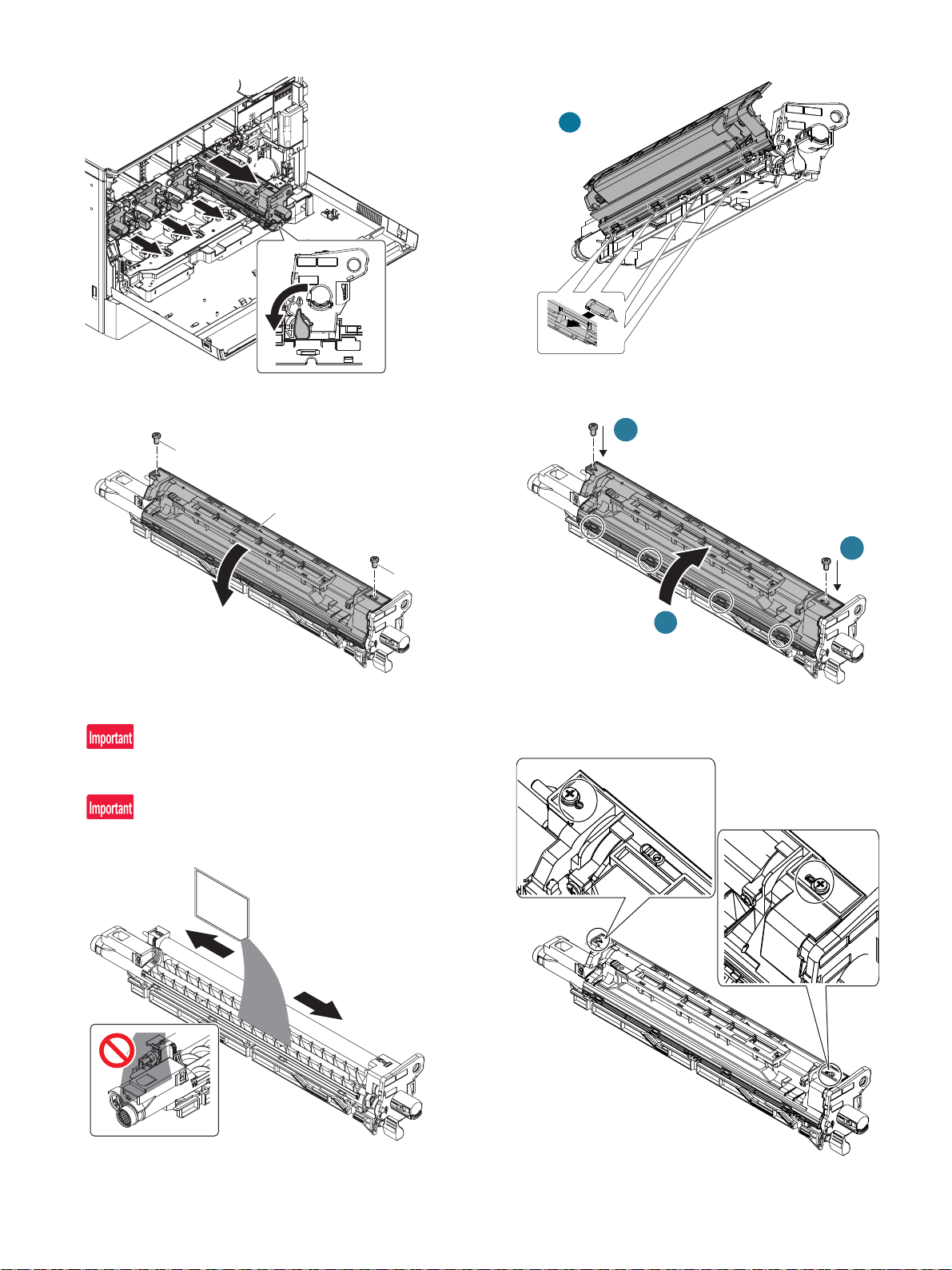
4) Raise a lever to the left. Pull out the developing unit to remove.
Ĭ
ĭ
Ĭ
Ĭ
ĭ
5) Open the cover to remove.
7) Attach the cover.
Close the cover. Fix the two screws. (Tightening torque: 0.5-0.6N/
m)
6) Loading developer to the developing units.
Be sure to shake the bag of developer thoroughly before pouring
into the developing unit.
When pouring the developer into the unit, use care to not get
developer into the drive section.
Check that the boss is fitted with the hole beside the screw on the
cover.
MX-4070N 2 – 16
Page 25
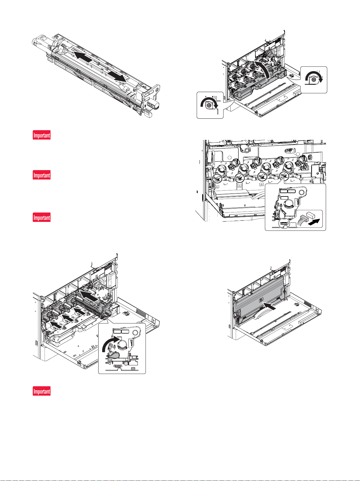
8) Shake the developing unit several times horizontally.
ĭ
Ĭ
ĭ
ĭ
Ĭ
Ĭ
After loading developer to the developing units, be sure to keep
the developing unit level while supplying the developer.
9) Insert the developing unit so as not to give a strong shock to the
main unit gently.Raise a lever to the right.
Slide the developing unit horizontally into the machine, in the
direction of the arrow, until developing unit locks into. place.
Do not push the unit diagonally, as contact with the drum may
occur causing damage.
10) Close the drum positioning cover, and lock it.
11) Connect the connecter.
When removing or installing the developing unit, put your hand
from below the unit and slide it in parallel along the guide.
At that time, be careful not to touch the roller surface.
When installing the machine, there is no need to remove or
install the OPC drum unit. If it must be removed or installed for
any reason, follow the procedures below. When removing or
installing the OPC drum unit, put your hand from below the unit
and slide it in parallel along the guide on the right side.
At that time, be careful not to touch the OPC drum surface.
12) Re-install the waste toner box and lock into place.
Both ends being locked surely.
MX-4070N 2 – 17
Page 26

(2) Set the control level for the reference toner density
Setting of the reference toner density control level must be performed
with the toner cartridge removed.
If setting is performed with the toner cartridge installed, the EE-EL
error or an over toner trouble may occur.
1) With the front cover opened, enter Sim25-2
2) Close the front cover
3) Select a developing unit to be adjusted
4) When [EXECUTE] key is pressed, it is highlighted. The DV roller
rotates and the toner density sensor detects toner density and the
output value is displayed.
The above operation is executed for 1 minutes and the average
value of the toner density sensor detection level is set (saves) as
the reference toner density control value.
When the reference toner density control adjustment operation is
completed [EXECUTE] key returns to normal from highlight.
This makes known about whether the adjustment operation is
completed or not.
The above operation is executed each of the lower speed mode
and the middle speed mode and the reference toner density control value is set for each of them.
8) Open the front cover and insert each toner cartridge
Be sure to install the color cartridge to their proper positions.
Avoid installation to a different color position.
Do not forcibly insert the toner cartridge.
Push it in until the cartridge is securely locked in place.
Developing units removed, be sure to remove the toner cartridges
as well to prevent toner clogging.
If the operation is interrupted within 1 minutes the adjustment
result is not reflected.
When [EXECUTE] key is pressed during the operation, the operation is stopped and [EXECUTE] key returns to the normal display.
If [EE-EU], [EE-EL] or [EE-EC] is displayed, setting of the reference toner density control value is not completed normally.
Troubleshoot the cause, remove the cause and perform setting
again.
Error display Error name Details of error
EE-EL EL abnormality Sensor output level less than 77 or
control voltage over 207
EE-EU EU abnormality Sensor output level over 177 or
control voltage less than 52
EE-EC EC abnormality Sensor output level other than 128
10
5) Exit Sim 25-2
6) Confirm that "Instal the toner cartridge " is displayed and instal the
toner cartridge by the following procedures
7) Shake the toner cartridge horizontally several times
Mounting location of the toner cartridge of each color
9) Close the front cover
10) Confirm that "Toner replacement in progress" is displayed and
wait until the display disappears (It takes 30 sec - 6 min)
This procedure is for checking the toner supply operation from the
toner cartridge to the DV unit. The operation time differs depending on the toner quantity in the toner cartridge, uneven distribution
of toner and the internal state of the toner cartridge.
Do not perform operations which interrupt the above operation
such as opening the front cover, entering the Sim mode and turning OFF/ON the power. If this precaution is ignored. Trouble
codes F2-40 - 43 or F2-64 - 67 or a over-toned condition may
occur.
MX-4070N 2 – 18
When the main unit is transported after the installation, be sure to
remove the DV unit and the Toner cartridge.
Then, be careful not to make the developer spilled out from the
mouth of the DV unit.
Page 27
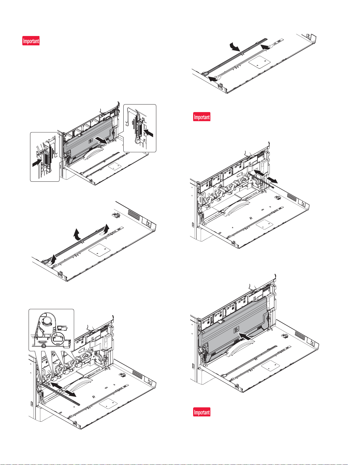
(3) Cleaning
Ĭ
Ĭ
ĭ
a. Cleaning of LSU's dust-proof glass and PTC wire
Dust from the transfer belt or shutter or some other adjacent part may
fall onto the LSU during transport or installation. Be sure to clean the
dust-proof glass and PTC wire before checking the image quality.
1) Open the front cabinet. Remove the waste toner box toward you
while pushing the unlocking levers on both sides of the waste
toner box.
4) Return the LSU cleaning rod to the front cabinet so that the felt
faces upward. Fit the boss, and fix it with three pawls.
5) Move the PTC cleaning rod back and forth a few times to clean
the PTC wire.
After completion of cleaning, insert the cleaning rod completely to
the bottom.
2) Detach the LSU cleaning bar from the front cover.
3) Turn the felt side of the cleaning bar downward and insert it. Slide
it back and forth a few times to clean the LSU dust-proof glass.
6) Attach the waste toner box.
Both ends being locked surely.
7) Close the front cabinet.
For the destination EXIT TRAY CABINET option.
Finisher or exit tray cabinet have to be installed before turning on
the machine otherwise get L4-11 code will occur.
MX-4070N 2 – 19
Page 28

(4) Paper feed tray setup
A
B
Ĭ
ĭ
a. System setting
1) Press the [SETTINGS] key.
2) Touch the [Init. Install Settings] key.
3) Touch the [Password] key at the Administrator Login.
Enter the password with 10-key. "admin"
4) Touch the [Paper Tray Settings] key to configure the settings.
These settings specify the paper type, paper size, and functions
allowed for each paper tray. When the [Tray Settings] key is
touched, a list appears showing the trays and the current settings.
5) Touch the [Each tray] key in the above screen to change the settings. The following settings can be configured.
Item Description
Type Select the type o f p a per tha t is loaded in t he tray. The
Size Select the paper size from the list. The pape r s ize s
Feeding Approved
Job
paper types that can be selected vary by paper tray.
that can be selected vary by tray. The sizes that can
be selected may also be restricted by the paper type
selected above.
If the desired size does not appear in the list, select
[Custom Size] and directly enter the size (only for the
bypass tray).
Select the modes that can be used. If there is a
function that you do not wish to be used with the
selected tray , disa ble the functio n. When th e "Type" is
other than plain paper, recycled paper, color ed p ap er,
or a user type, [Fax] and [Internet Fax] cannot be
selected.
b. Tray size setup
1) Pull out the paper tray.
Gently pull the tray out until it stops.
If paper remains in the tray, remove it.
2) Adjust the guide plates A and B by squeezing their lock levers and
sliding them to match the vertical and horizontal dimensions of the
paper to be loaded.
The guide plates A and B are slidable. Slide each guide plate
while squeezing its lock lever.
3) Adjust the guide plates A and B by squeezing their lock levers and
MX-4070N 2 – 20
Page 29
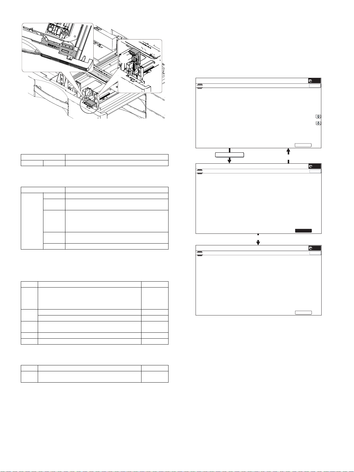
(2) Description
Į
EXECUTE
6,08/$7,21ǂǂ12
$872$'-8670(172)5(*,675$7,21'580326,7,21
12:(;(&87,1*
(;(&87(
$872$'-8670(172)5(*,675$7,21'580326,7,21
35(66>(&(;87(@7267$57
(55257211(5(037<
(;(&87(
$872$'-8670(172)5(*,675$7,21'580326,7,21
0$,1)0$,1568%6.(:3+$6(
&/1*
0/1*
</1*
$//B527$7(/2.
(;(&87(
Adjustment completed
Abnormal end
a. Print engine image di storti on ad just men t (Man ual adju stm ent)
/ OPC drum phase adjustment (Automatic adjustment) / Co lor
registration adjustment (Automatic adjustment)
This adjustment performs the print engine image distortion adjustment,
the OPC drum phase adjustment, and the color registration adjustment simultaneously.
1) Enter SIM50-22 mode.
(5) Specifications setup
Use simulation 26-6 to set the machines destination.
SIM No Content
26 6 Used to set the destination.
After completion of destination settings, change the set values to customize the following settings.
SIM No Content
26 3 Used to set the auditor specification mode.
5 Used to set the count mode of the total counter an d
18 Used to set YES/NO of the toner save mode (Onl y in
52 Used to set YES/NO of counting when non-print
C. Image quality check
(1) Execution items
Execute the following items.
65 Used to set the limit number of sheets for stapling.
the maintenance counter.
UK and Japan versions)
* For other destination versions, this setup is made
by the user program.
paper is passed through each counter.
ǂǂǂ6,08/$7,21ǂǂ12
7(67
ǂǂ
7(67
ǂǂ6,08/$7,21ǂǂ12
7(67
&/26(
&/26(
&/26(
No. Item SIM
1 Print engine image distortion adjustment (Manual
adjustment) / OPC drum phase adjustment
(Automatic adjustment) / Color registration adjustment
(Automatic adjustment)
2 Clear the laser power correction value 61-13
FR density variation correction 61-11
3 Copy/Printer color balance and density adjustment
(Automatic adjustment)
4 Copy color balance and density check
5 Printer color balance/density check 64-5
When there are defects in a picture by the contents mentioned above,
you carry out the following contents, and confirm a picture.
No. Item SIM
6 Print/scan image off-center, lead edge position
adjustment
50-22
46-74
50-10
MX-4070N 2 – 21
Page 30
2) Press [EXECUTE] key.
[EXECUTE] key is highlighted and the image registration auto-
matic adjustment is started. (It takes about 30 sec to complete the
adjustment.)
3) When the adjustment is completed, [EXECUTE] key returns to the
normal display, and the value of the adjustment result is displayed.
The current skew level for each color is displayed on the SKEW
display section.
4) Write down the displayed skew level.
(Meaning of the skew level value and the adjustment procedure)
* If "OK" is displayed for all items of SKEW C,
M, and Y, there is no need to perform the adjustment.
* When "R" is displayed at the head of the value, turn the LSU
skew adjustment screw clockwise.
* When "L" is displayed at the head of the value, turn the LSU
skew adjustment screw counterclockwise.
* The turning amount of the adjustment screw corresponds to
each adjustment value. C, M, and Y indicate numbers of clicks.
The display value is rounded at the decimal point.
* "C, M, and Y(SKEW)" shows the number of adjustment click
steps for each adjustment screw of C, M, and Y.
Contents in ( )
MIAN, SUB: Difference from the previous adjustment value of
image registration.
Example:
If 105 for this time and 103 for the previous time,
it is displayed as 105.0 (+2.0).
SKEW: Judgment of the LSU skew adjustment result. OK or NG.
PHASE: OPC drum phase adjustment value of the previous time
5) The procedures 2) to 4) again, and check to confirm that C, M,
and Y (SKEW) are OK.
If any of them is NG, turn the LSU skew adjustment screw of the
corresponding color to adjust.
When the adjustment is made by turning the LSU skew adjustment
screw of K, the states of C, M and Y (SKEW) are changed. Execute
SIM50-22 to check to confirm that C, M, and Y (SKEW) are OK.
When an abnormality occurs, "ERROR" is displayed.
In this case, check each drive section and the process section.
b. FR density variation correction
Before executing this adjustment, be sure to check the fo llowing
items.
* There must be a tray with A4 (LT) paper in it.
A. Clear the laser power correction value
1) Enter the SIM 61-13 mode.
2) Press [EXECUTE] key. And press [YES] key.
Press [EXIT] key and reboot.
B. FR density variation correction
1) Enter the SIM 61-11 mode.
2) Press [DATA] key. Confirm that all the values become 50.
3) Press [BACK] key and return to SIM61-11 mode screen.
Press [AUTO CORRECTION] key.
4) Press [EXECUTE] key, and self printing of the adjustment patch is
started.
5) Set the printed sample so that the arrow direction is fit with the left
edge section for scanning on the OC in the A4R(LTR) direction,
and press [EXECUTE] key. Place 5 sheets of white paper on the
printed adjustment pattern.
6) After pattern reading for the adjustment, the adjustment result pattern is printed automatically, and adjustment is completed.
MX-4070N 2 – 22
Page 31
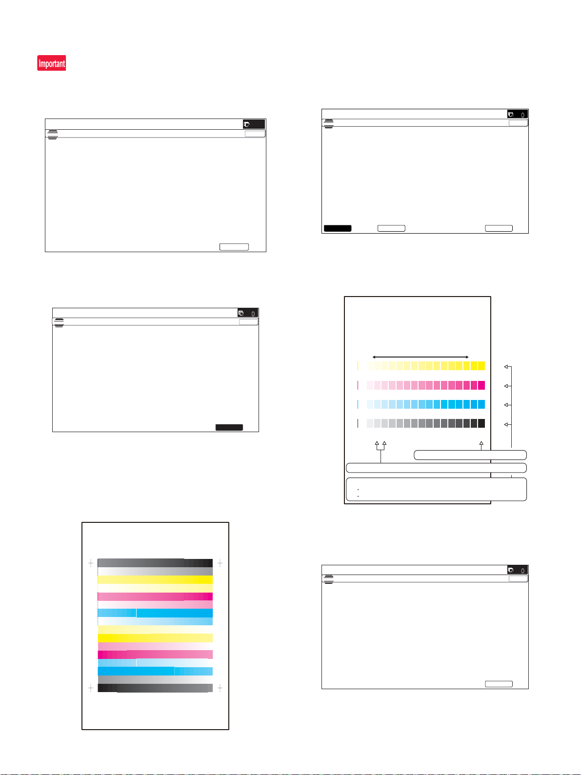
c. Copy/Printer color balance and density adjustment (Automatic
6,08/$7,21ǂǂ12
1*,1($872$'-8670(176(59,&(
(;(&87(
5(66>(;(&87(@72352&21(;(&87,21$1'35,177+(7(673$7&+
)257+,6$'-8670(17
ǂǂǂ6,08/$7,21ǂǂ12
&/26(
7(67
(1*,1($872$'-8670(176(59,&(
(;(&87(
352&21(;(&87,1*
ǂǂǂ6,08/$7,21ǂǂ12
&/26(
7(67
(1*,1($872$'-8670(176(59,&(
3/($6(6(/(&77+(02'()$&725<256(59,&($1'3/$&(
7+(35,17('7(673$7&+21'2&80(17*/$667+(135(66>(;(&87(@
/,*+7$5($$7/()76,'(21'2&80(17*/$66
(;(&87(6(59,&()$&725<
QOPNMLKJIHGFEDCBA
Y
M
C
Bk
High
density
Low
density
1) The max. density section is not blurred.
2) Patch C or D of each of Y, M, C, and BK is very slightly copied.
3) Patch for each of Y, M, C, BK
The patch density is identical between patches or not reversed.
The patch density is changed gradually.
ǂǂǂ6,08/$7,21ǂǂ12
&/26(
7(67
(1*,1($872$'-8670(176(59,&(
&21),507+($'-3$7&+$1'35(66>(;(&87(@72$'-2)5(*,675$7,21(;(
$1'35,177+(7(673$7&+
3/($6(86(63(&,),('7<3(2)$25h6,=(3$3(5
)257+,6$'-8670(17
(;(&87(
adjustment)
When a printer option is installed, be sure to execute the above item.
1) Enter the SIM46-74 mode.
4) Select [FACTORY] target, and press [EXECUTE] key.
When the color balance is customized by the manual color bal-
ance adjustment (SIM 46-21) according to the user's request, and
the color balance is registered with SIM63-7 as the service target,
if the color balance is required to be adjusted, select the [SERVICE] target.
ǂǂǂ
7(67
(
3
3/($6(86(63(&,),('7<3(2)$$25;;6,=(3$3(5
2) Press [EXECUTE] key.
The high density process control is performed, and the copy color
patch image (adjustment pattern) is printed out.
(A4/11" x 8.5" or A3/11" x 17" paper is automatically selected.)
&/26(
The copy color balance adjustment is automatically executed and
prints the color balance check patch image.
If there is any streak or unclear print on the printed check pattern,
check the print engine for any problems.
3) Set the color patch image (adjustment pattern) paper printed in
procedure 2) on the document table.
Set the color patch image (adjustment pattern) printed in the procedure 2) on the document table. Place the color patch image so
that the fine lines are on the left side. At that time, place 5 sheets
of white paper on the printed color patch image (adjustment pattern).
5) Press [EXECUTE] key.
The printer color patch image (adjustment pattern) is printed out.
(A4/11" x 8.5" or A3/11" x 17" paper is automatically selected.)
MX-4070N 2 – 23
Page 32
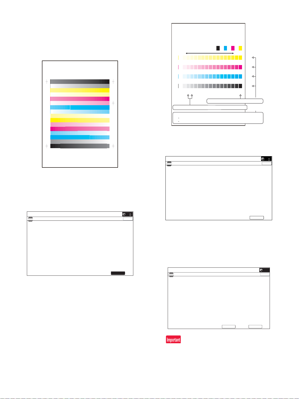
6) Set the color patch image (adjustment pattern) printed in the pro-
PRINTER CALIBRATION
ǂǂǂ6,08/$7,21
ǂǂ12
&/26(
7(67
(1*,1($872$'-8670(176(59,&(
2.
3/($6(:$,7
12:5(*,67(5,1*7+(1(:7$5*(72)+$/)721(352&2167
PRINTER CALIBRATION
3120/.-,+*)('&%$#
;
/
%
$M
1) The max. density section is not blurred.
2) Patch C or D of each of Y, M, C, and BK is copied.
3) Patch for each of Y, M, C, BK
The patch density is identical between patches or not reversed.
The patch density is changed gradually.
High densityLow density
ǂǂǂ6,08/$7,21ǂǂ12
&/26(
7(67
(1*,1($872$'-8670(176(59,&(
&21),507+($'-867('3$7&+$1'35(66>2.@725(*,67(57+,63$7&+'$7$
2.
6,08/$7,21ǂǂ12
1*,1($872$'-8670(176(59,&(
5(75<
203/(7(7+,6352&('85(
/($6(48,77+,602'(
.
5(68/7
cedure 5) on the document table.
Set the color patch image (adjustment pattern) printed in the pro-
cedure 2) on the document table. Place the color patch image so
that the fine lines are on the left side. At that time, place 5 sheets
of white paper on the printed color patch image (adjustment pattern).
8) The initial setting menu of the half-tone image correction is displayed. Press [OK] key.
The initial setting of the half-tone image correction is performed.
7) Select [FACTORY] target, and press [EXECUTE] key.
When the color balance is customized with the manual color bal-
ance adjustment (SIM 67-25) according to the user's request and
the color balance is registered as the service target with SIM 6727, if the color balance is adjusted to that color balance, select the
[SERVICE] target.
The printer color balance adjustment (step 1) is automatically performed and the color balance check patch image is printed out.
If there is any streak or unclear print on the printed check pattern,
check the print engine for any problems.
9) Wait until [EXECUTE] key is displayed. When it is displayed,
press it.
The half-tone image correction is performed.
10) When "COMPLETED THIS PROCEDURE" is displayed, the
adjustment operation is completed.
Cancel SIM46-74.
ǂǂǂ
7(67
(
&
3
2
&/26(
The adjustment result becomes valid only when the both adjustments in the copy mode and in the printer mode are completed.
For example, if the copy color balance adjustment (automatic
adjustment) is performed and the simulation is canceled, the
adjustment result is invalid.
MX-4070N 2 – 24
Page 33
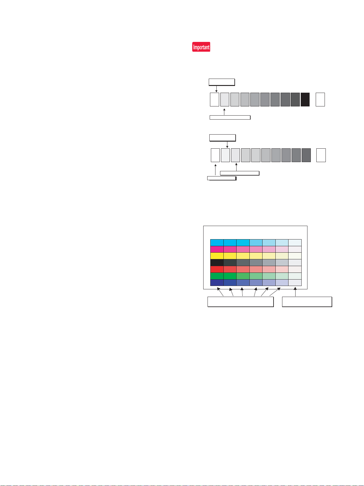
11) Check the copy color balance and density.
12345678910 W
SHARP GRAY CHART
SHARP gray chart
Patch 1 is
slightly copied.
Patch 2 is copied.
(Color copy)
12345678910 W
SHARP GRAY CHART
SHARP gray chart
Patch 1 is not copied.
Patch 2 is
slightly copied.
Patch 3 is copied.
(Black-and-white copy)
Serviceman chart (Color patch section)
The densities of patches 1 - 6 of
each color are properly balanced.
Patch 7 is slightly
copied or not copied.
(Color copy)
(Refer to the item of the copy color balance and density check.)
12) Check the printer color balance and density.
(Refer to the item of the printer color balance and density check.)
If the color balance or density is not in the satisfactory level even after
execution of the automatic and manual adjustments, there may be
another cause.
Troubleshoot the cause, repair or perform necessary works, and
repeat the adjustment from the beginning.
If color balance or density is not satisfied, adjust the copy and printer
color balance by SIM 46-74.
d. Copy color balance and density check
Method
Make a copy of the gray test chart (UKOG-0162FCZZ) and a copy of
the servicing color test chart (UKOG-0326FCZZ/UKOG-0326FC11),
and check that they are proper.
a. Note for execution of the color balance and density check in the
color copy mode
To check the copy color balance and density, use the gray test chart
(UKOG-0162FCZZ) and the servicing color test chart (UKOG0326FCZZ/UKOG-0326FC11). Set the copy density level to "3" in
the Text/Printed Photo mode (Manual), and make a copy.
At that time, all the color balance adjustments in the user adjustment
mode must be set to the default (center).
In addition, be sure to use the specified paper for color.
b. Note for checking the monochrome copy mode density
To check the density, use the gray test chart (UKOG-0162FCZZ).
Set the copy density level to "Manual 3" in the Text/Pr inted Photo
mode (Manual).
In addition, all the color balance adjustments in the user adjustment
mode must be set to the default (center).
[Check with the gray test chart (UKOG-0162FCZZ)]
In the copy density check with the gray test chart, check to insure the
following conditions.
For the color (gray) balance, use the servicing color test chart (UKOG0326FCZZ/UKOG-0326FC11) to check.
[Check with the servicing color test chart (UKOG-0326FCZZ/UKOG0326FC11)]
In the copy color balance check with the servicing color test chart,
check to insure the following conditions.
MX-4070N 2 – 25
Page 34
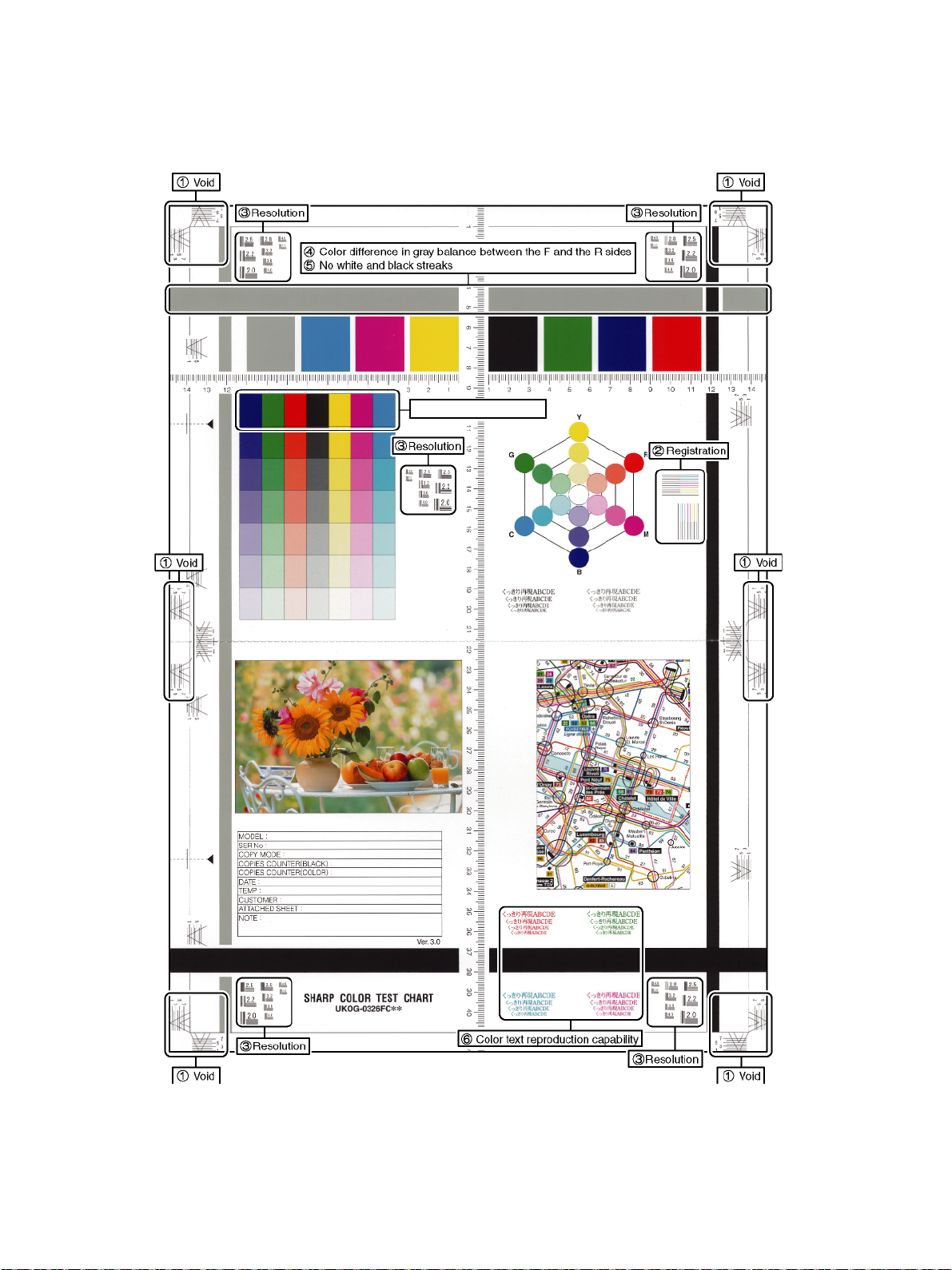
a. Color copy check items (Check to confirm the following:)
Solid density is not so light
IJ
1) There are 12 void areas.
2) Registrations (one point for the main scanning, and one point for
the sub scanning) are not shifted.
3) The resolution of 5.0 (5 points) can be seen.
4) The color difference in gray balance between the F and the R
sides is not so great.
5) There are no white and black streaks.
6) Color texts are clearly reproduced.
7) Solid density is not so light.
MX-4070N 2 – 26
Page 35
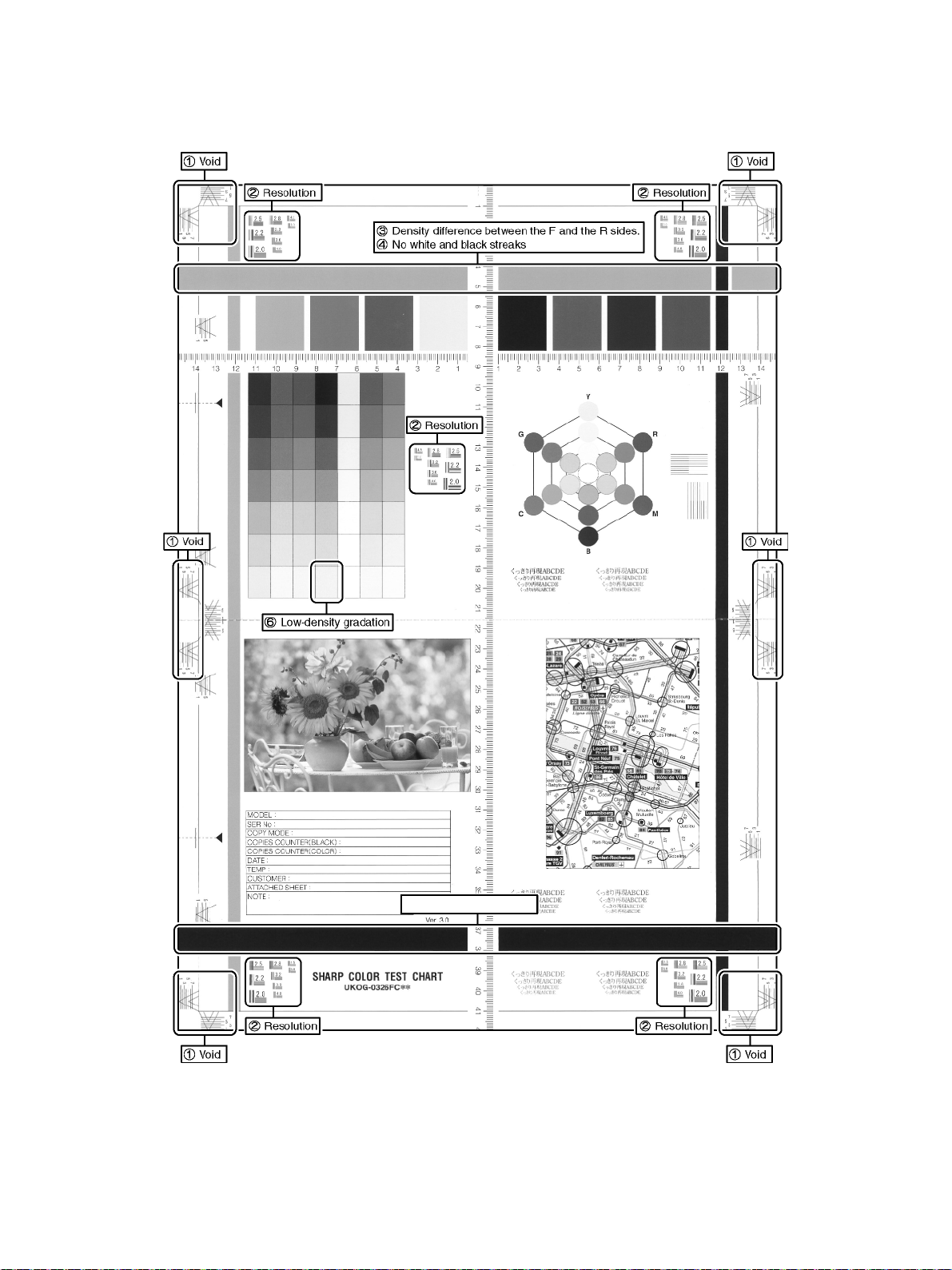
b. Monochrome copy check items (Check to confirm the following:)
Solid density is not so light
İ
1) There are 12 void areas.
2) The resolution of 4.0 (5 points) can be seen.
3) The density difference between the F and the R sides is not so
great.
4) There are no white and black streaks.
5) Solid density is not so light.
6) The black low-density gradation is copied slightly.
MX-4070N 2 – 27
Page 36
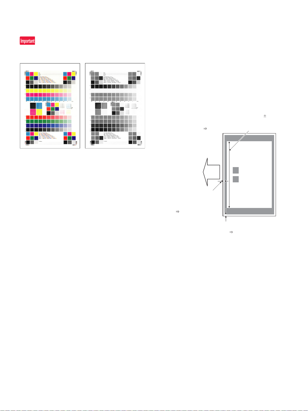
e. Printer color balance/density check
• Lead edge void amount
(4.0mm terget)
Measure at the center of
paper.
Adjustment value
J : SUB-CS
Print
lead edge
Main scanning magnification ratio (240 0.5mm)
Measure the dimension near the inner frame line
and the paper lead edge in parallel with the line.
Adjustment value A : BK-MAG
• F side void amount (2.0mm terget)
Measure at a position near the
paper lead edge.
Adjustment value
C : MAIN-CS1
Method
Execute SIM 64-5 to print the print test pattern.
Set each set value to the default and press [EXECUTE] key. The print
test pattern is printed.
The print density must be changed gradually from the lighter level to
the darker level. The density changing direction must not be reversed.
The density level of each color must be almost at the same level.
f. Print/scan image off-center, lead edge position adjustment
Before executing this adjustment, be sure to check the fo llowing
items.
* There must be a tray with A4 (LT) paper in it.
1) Enter the Sim. 50-10 mode.
2) Select a paper feed source “2“ (CS1).
3) Set A4 (11 X 8.5) paper on the CS1 paper feed tray.
4) Check to confirm that the inside dimension of the printed half-tone
pattern is 2400.5mm.
If the above condition is not satisfied, follow and repeat the procedures of ADJ4A(Service manual) until a satisfactory result is
obtained.
5) Measure the void area size of the adjustment pattern in the front/
rear frame direction (F side void amount) and that in the transport
direction (Lead edge void amount).
Check to confirm that all the following conditions are satisfied.
Calculation and input procedures of adjustment values
(Example) Lead edge void amount
(1) Measure by visual inspection.
Measurement result: 4.5mm
(2) Calculate the shift amount.
The target value is the specification value (center value) of
3mm.
* For the F side void amount, the target is 2mm.
[4 – 4.5 = -0.5 (mm)]
(3) Calculate the adjustment value.
Subtract 5 from the shift amount of -0.5mm.
* For the shift amount of 0.1mm, the adjustment value is
varied by 1.
When the current value is 50:
[50 – 5 = 45]
(4) Enter the adjustment value for SUB-CS.
Enter the [45].
6) Enter MAIN-CS1 (F side void) and SUB-CS (Lead edge void), and
press OK button.
Enter the calculated adjustment values for the shift amount to
MAIN-CS1/SUB-CS, and press OK button. (The cursor can be
used instead of the button.)
7) After entering the adjustment values, print again and check to
confirm that the avoid amounts are adjusted to the target range.
MX-4070N 2 – 28
Page 37
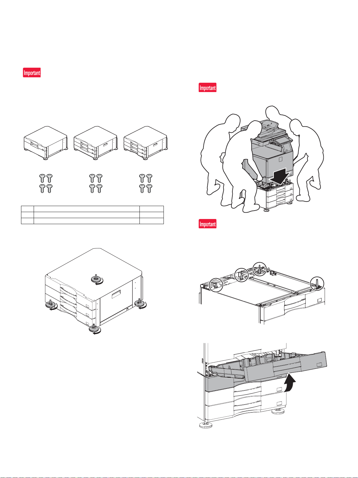
1
MX-DE27MX-DE26MX-DE25
2
1
2
1
2
MX-4070N
[3] MX-DE25/DE26/DE27/DE29 (STAND/1x550/2x550/3x550/1x550(Low) SHEET
Service Manual
PAPER DRAWER)
1. Unp acking & Installation
A. MX-DE25/DE26/DE27
(3) Main unit and desk unit connection
Before installation, be sure to turn both the operation and main power
switches off and disconnect the power plug from the power outlet.
Make double sure that the data lamp on the operation panel does not
light up or blink when performing installation.
(1) Packed items check
1) Put the main unit on the desk unit.
Use man power of four persons or more to lift the main unit.
No. Name Quantity
1 Desk unit 1
2 Fixing screws (M4 x 8) 4
(2) Right adjuster attachment
1) Turn each adjuster to fix the desk unit.
Place the main unit on the desk unit slowly by fitting the external
lines. Check to insure that the positioning pin on the top of the
desk unit is securely engaged in the positioning groove of the
main unit.
2) Remove the tray 1 and the tray 2.
MX-4070N MX-DE25/DE26/DE27/DE29 (STAND/1x550/2x550/3x550/1x550(Low) SHEET PAPER DRAWER) 3 – 1
Page 38
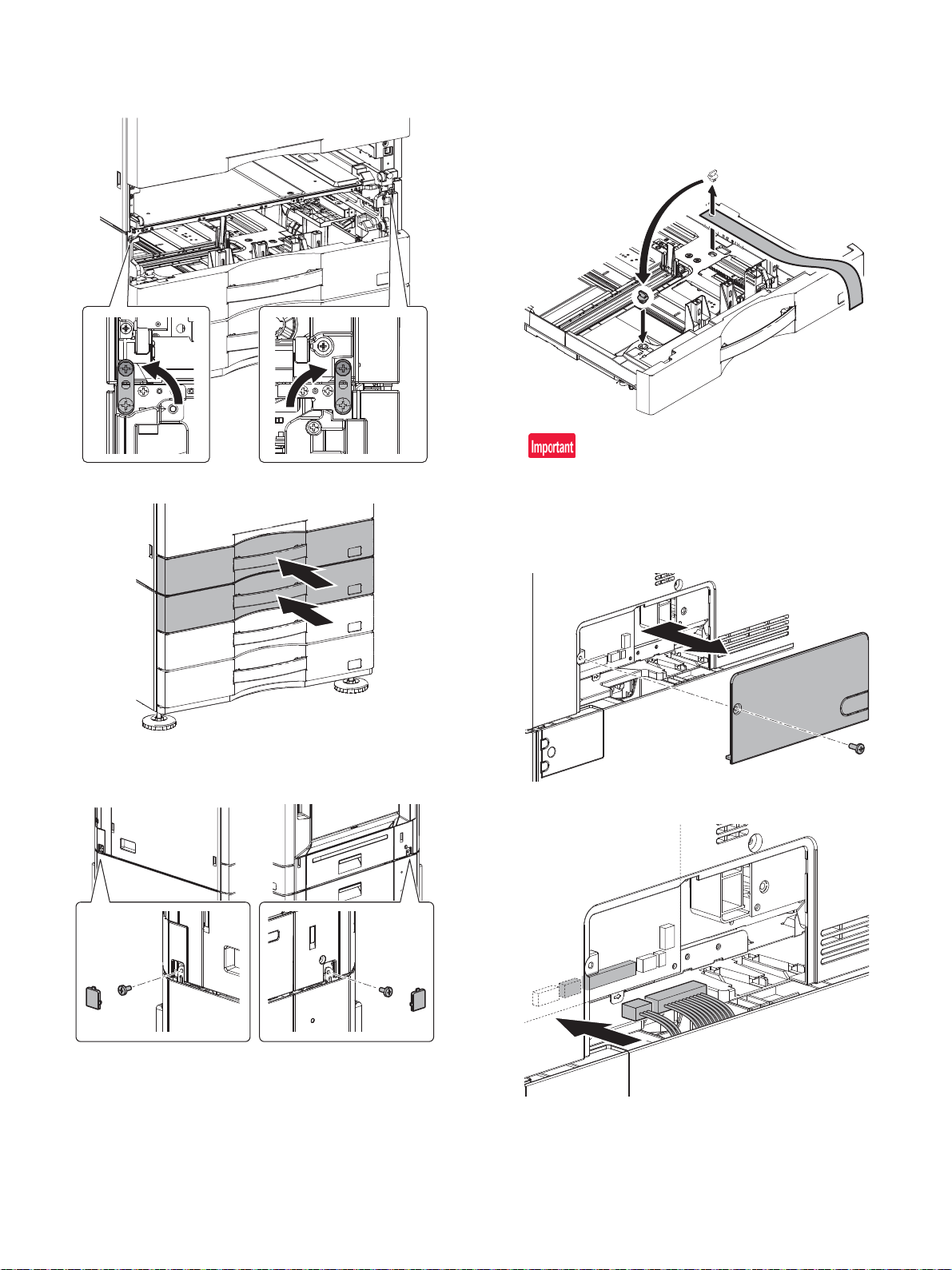
3) Raise the linkage plates on the right and left sides of the front side
of the desk unit, and fix them with the fixing screws included in the
package.
(4) Release the lock
1) Pull out each tray. Turn and remove the fixing material, and
remove the caution sheet.
Attach the removed fixing material to the position shown in the figure for storage.
Close the cassette which was pulled out.
4) Attach the tray 1 and the tray 2.
5) Take off the small cover of right and left sides of the main body
rear. And fix them with the fixing screws included in the package.
Return small covers.
Before turning on the power, check to insure that the fixing material of the tray is disengaged. If the power is turned on without disengaging the fixing material, a trouble may be resulted.
(5) Connector connection
1) Remove the cover from the rear side of the machine.
2) Connect the connector.
MX-4070N MX-DE25/DE26/DE27/DE29 (STAND/1x550/2x550/3x550/1x550(Low) SHEET PAPER DRAWER) 3 – 2
Page 39

3) Separate the base of the cover in nippers.
4) Attach the cover.
MX-4070N MX-DE25/DE26/DE27/DE29 (STAND/1x550/2x550/3x550/1x550(Low) SHEET PAPER DRAWER) 3 – 3
Page 40
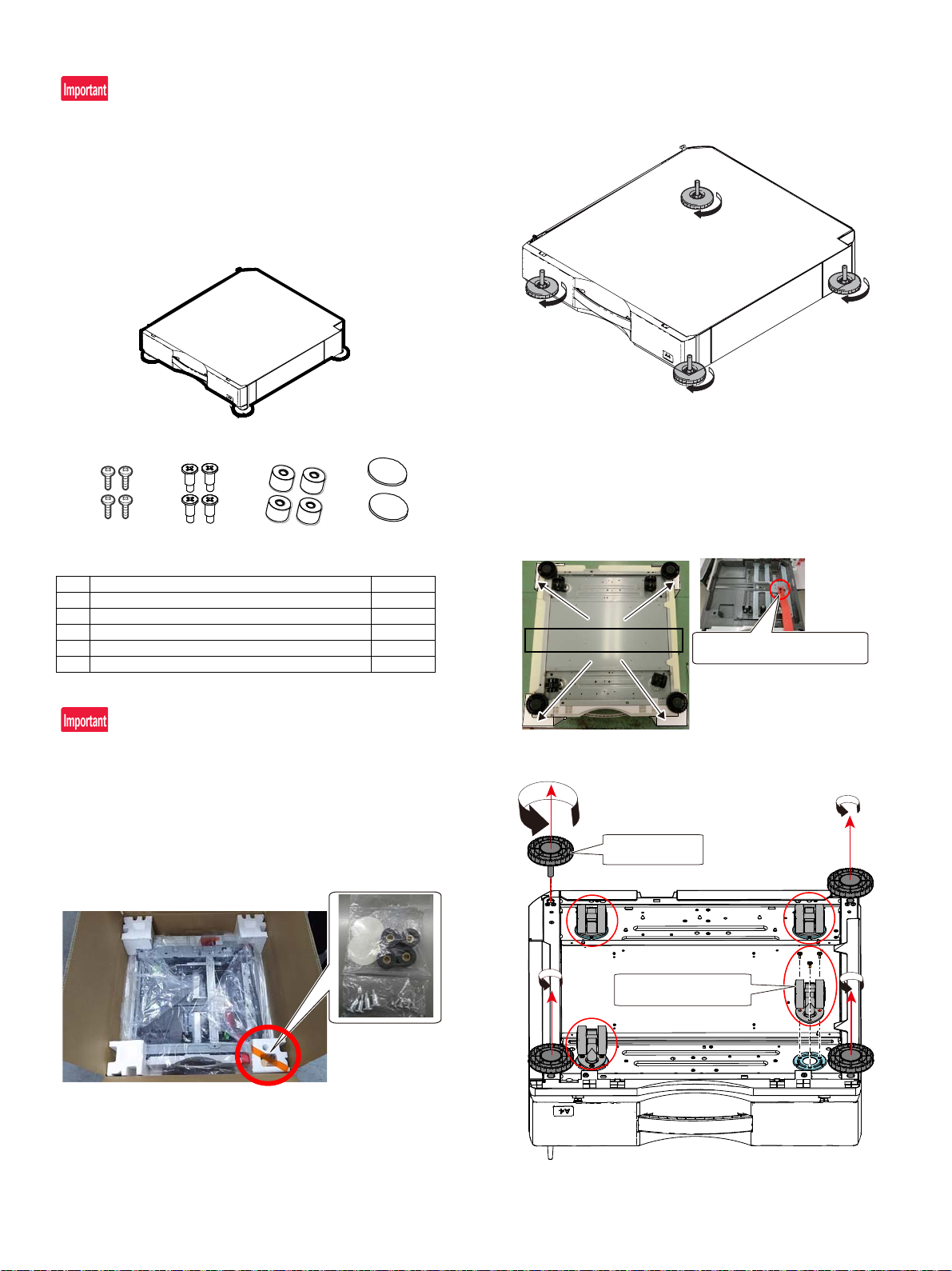
B. MX-DE29
MX-DE29
1
4
3
2
5
Toppackingcushion
Donʼtremovefixingmaterial.
Removescrewsandacaster.
Removeanadjuster.
If a connector is removed out of a plastic bag prior to the connection, it
may get caught in the gap between the drawer and main unit. Do not
remove the connector while unpacking the drawer. Remove it when
connecting the connector after installation to main unit.
(1) Unpacking
a. Packed items check
(2) Installation location
a. For installation on the floor
1) Rotate each adjuster to fix and secure Desk unit.
b. For installation on desktop
1) Place packing material (Top packing cushion for four corners) on
the floor and turn the paper drawer upside down.
*NOTE: Turn the paper drawer upside down without removing fixing material. Otherwise, a rotating plate may damage the paper
drawer.
This work must be done by two or more personnel.
No. Name Quantity
1 Desk unit 1
2 Fixing screws (M4 x 8) 4
3 Fixing stepping screws *1 4
4 Rubber foot*1 4
5 Bottom sheet*1 2
*1: These items will be required for desktop installation.
Before installation, be sure to turn both the operation and main power
switches off and disconnect the power plug from the power outlet.
Make double sure that the data lamp on the operation panel does not
light up or blink when performing installation.
b. Packed items removal
1) Remove the packed items fixed with a tape as follows.
2) Remove all adjusters and casters.
MX-4070N MX-DE25/DE26/DE27/DE29 (STAND/1x550/2x550/3x550/1x550(Low) SHEET PAPER DRAWER) 3 – 4
Page 41
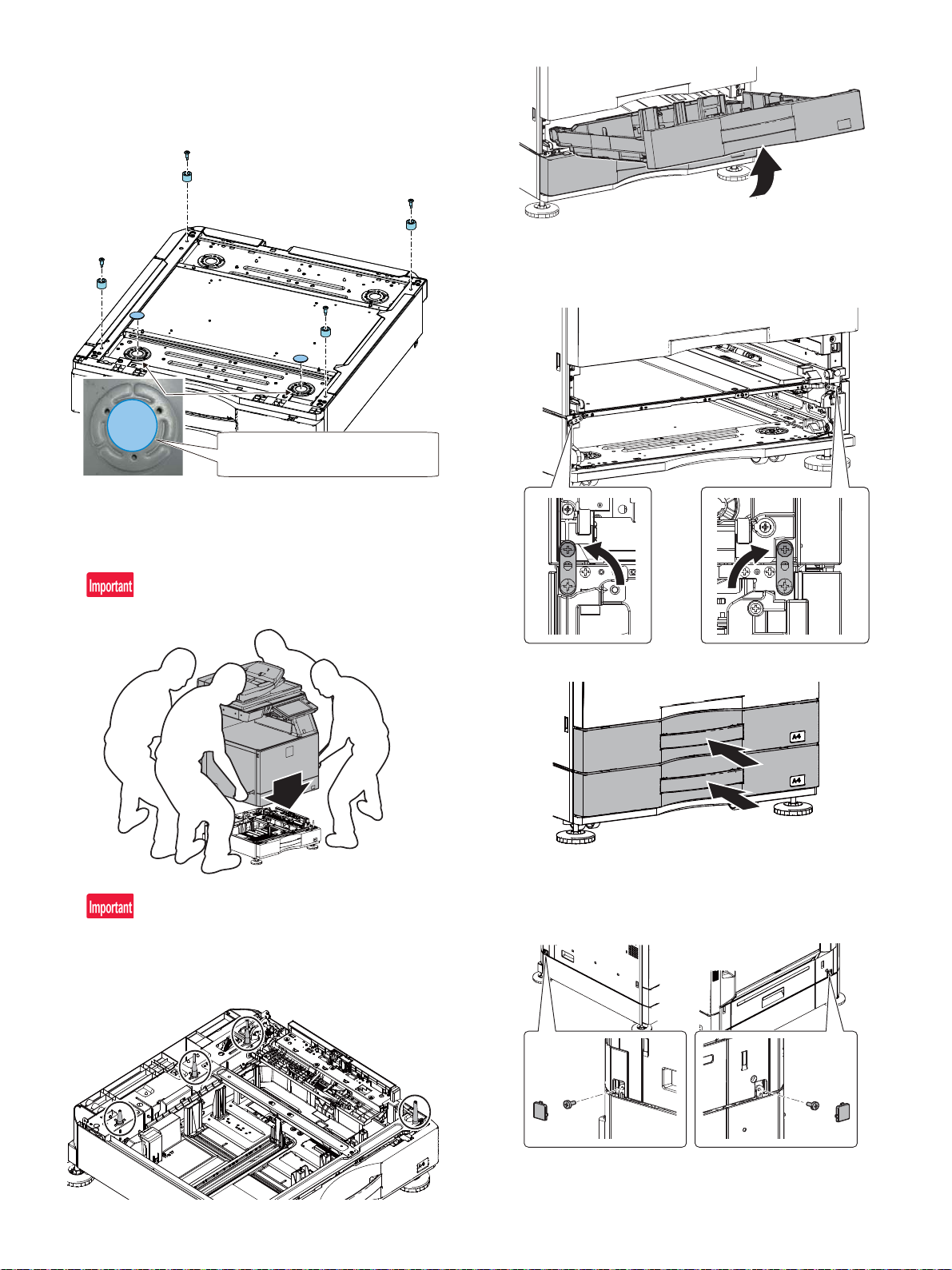
3) Attach the packed Rubber foot (Packed item No.4) using a Fixing
Attachthesheetcoveringahole.
*Setroundingedgeofprocessedmetalasa
reference.
stepping screws (Packed item No.3). Then attach Bottom sheet
(Packed item No.5) to the holes (at two sections) close to the handle.
*The sheet does not need to be attached on rear holes.
4) Turn the paper drawer back to original position and install it to
main unit.
(3) Main unit and desk unit connection
1) Put the main unit on the desk unit.
3) Raise the linkage plates on the right and left sides of the front side
of the desk unit, and fix them with the fixing screws included in the
package.
Use man power of four persons or more to lift the main unit.
Place the main unit on the desk unit slowly by fitting the external
lines. Check to insure that the positioning pin on the top of the
desk unit is securely engaged in the positioning groove of the
main unit.
4) Attach the tray 1 and the tray 2.
5) Take off the small cover of right and left sides of the main body
rear. And fix them with the fixing screws included in the package.
Return small covers.
2) Remove the tray 1 and the tray 2.
MX-4070N MX-DE25/DE26/DE27/DE29 (STAND/1x550/2x550/3x550/1x550(Low) SHEET PAPER DRAWER) 3 – 5
Page 42
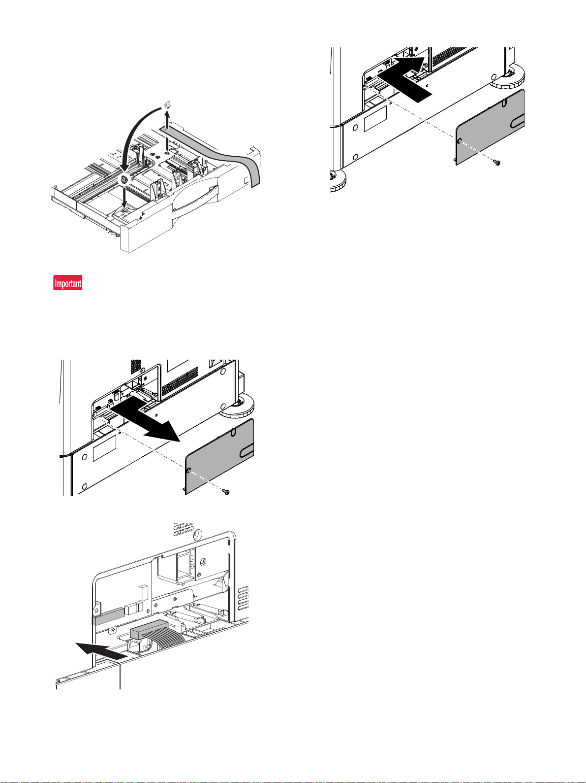
(4) Release the lock
1) Pull out each tray. Turn and remove the fixing material, and
remove the caution sheet.
Attach the removed fixing material to the position shown in the figure for storage.
Close the cassette which was pulled out.
Before turning on the power, check to insure that the fixing material of the tray is disengaged. If the power is turned on without disengaging the fixing material, a trouble may be resulted.
(5) Connector connection
1) Remove the cover from the rear side of the machine.
3) Attach the cover.
2) Connect the connector.
MX-4070N MX-DE25/DE26/DE27/DE29 (STAND/1x550/2x550/3x550/1x550(Low) SHEET PAPER DRAWER) 3 – 6
Page 43
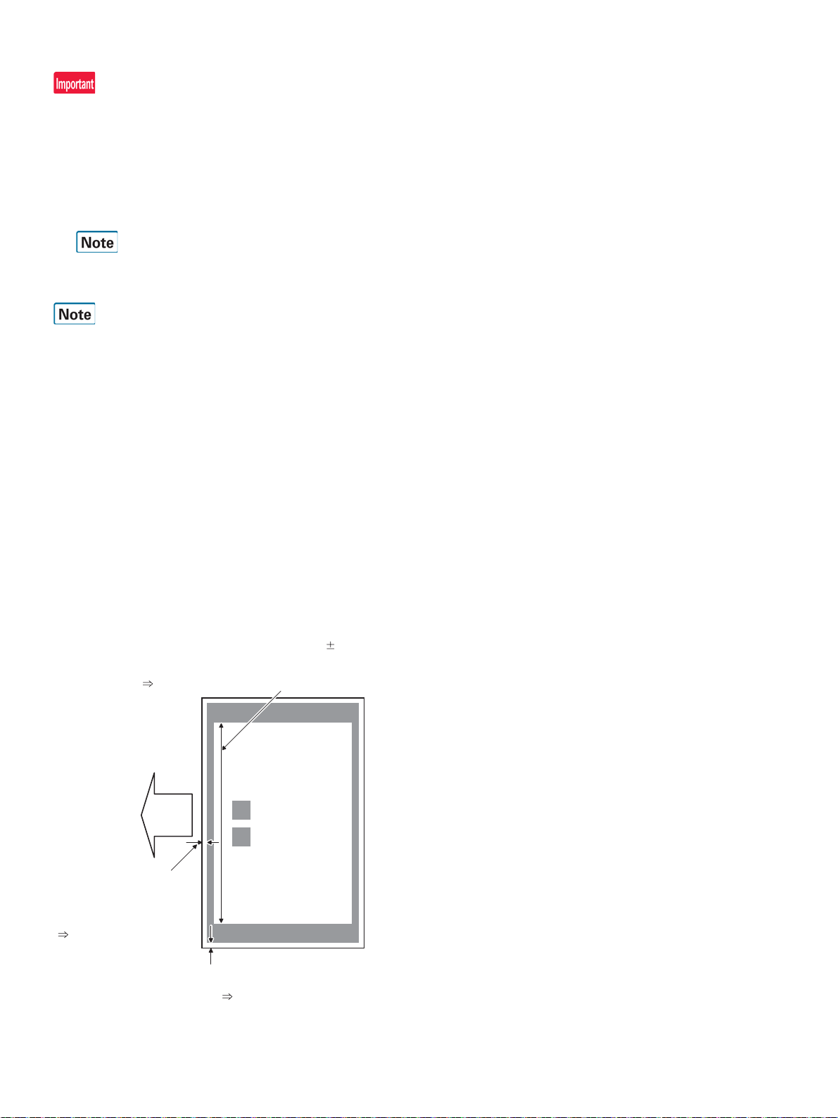
2. Adjustment
• Lead edge void amount
(4.0mm terget)
Measure at the center of
paper.
Adjustment value
K : SUB-DSK
Print
lead edge
Main scanning magnification ratio (240 0.5mm)
Measure the dimension near the inner frame line
and the paper lead edge in parallel with the line.
Adjustment value A : BK-MAG
• F side void amount (2.0mm terget)
Measure at a position near the
paper lead edge.
Adjustment value
D : MAIN-CS2
E : MAIN-CS3
F : MAIN-CS4
Before installation, be sure to turn both the operation and main power
switches off and disconnect the power plug from the power outlet.
Make double sure that the data lamp on the operation panel does not
light up or blink when performing installation.
A. Turn ON the power of the main unit
1) Connect the power plug of the machine to the power outlet, and
turn ON the main power switch and the operation panel power
switch.
For setting the tray size, refer to “Tray size setup” (1-6).
B. Image off-center adjustment
The image lead edge position and the off-center adjustment value of
the desk unit have been set to the average value when shipping from
the factory.
Therefore, this adjustment must be performed only when the judgment
is made to execute it through checking the print image.
* There must be a tray with A4 (LT) paper in it.
1) Enter the Sim50-10 mode.
2) Select a paper feed source “3“ (CS2).
3) Set A4 (11 X 8.5) paper on the CS2 paper feed tray.
4) Check to confirm that the inside dimension of the printed half-tone
pattern is 2400.5mm.
If the above condition is not satisfied, follow and repeat the procedures of ADJ4A(Service manual) until a satisfactory result is
obtained.
5) Measure the void area size of the adjustment pattern in the front/
rear frame direction (F side void amount) and that in the transport
direction (Lead edge void amount).
Check to confirm that all the following conditions are satisfied.
Calculation and input procedures of adjustment values
(Example) Lead edge void amount
(1) Measure by visual inspection.
Measurement result: 4.5mm
(2) Calculate the shift amount.
The target value is the specification value (center value) of
3mm.
* For the F side void amount, the target is 2mm.
[4 – 4.5 = -0.5 (mm)]
(3) Calculate the adjustment value.
Subtract 5 from the shift amount of -0.5mm.
* For the shift amount of 0.1mm, the adjustment value is
varied by 1.
When the current value is 50:
[50 – 5 = 45]
(4) Enter the adjustment value for SUB-DSK.
Enter the [45].
6) Enter MAIN-CS2 (F side void) and SUB-DSK (Lead edge void),
and press OK button.
Enter the calculated adjustment values for the shift amount to
MAIN-CS2/SUB-DSK, and press OK button. (The cursor can be
used instead of the button.)
7) After entering the adjustment values, print again and check to
confirm that the avoid amounts are adjusted to the target range.
Perform procedures 4) to 7) for each paper feed tray.
MX-4070N MX-DE25/DE26/DE27/DE29 (STAND/1x550/2x550/3x550/1x550(Low) SHEET PAPER DRAWER) 3 – 7
Page 44
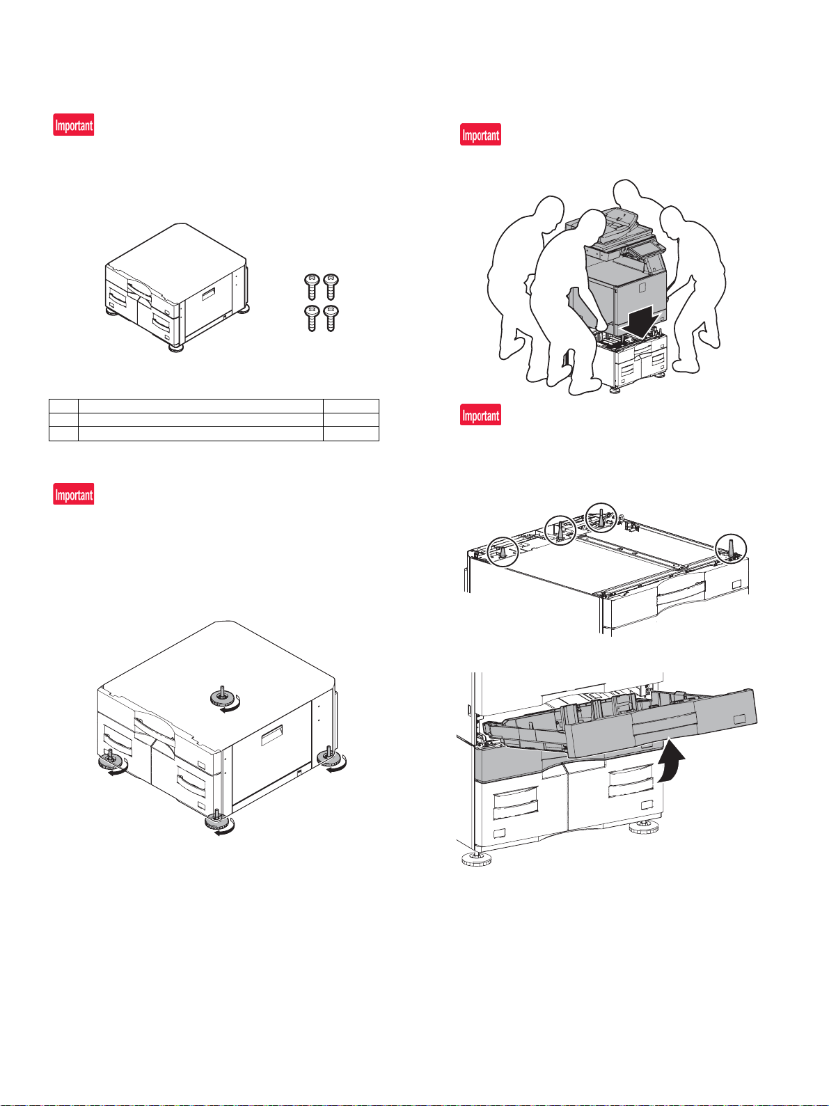
21
MX-4070N
[4] MX-DE28 (STAND/500&2100 SHEET PAPER DRAWER)
Service Manual
1. Unpacking
If the connector is removed first, it may be damaged during the installation procedures. Therefore, keep it packed while un-boxing. and
unpack it only when connecting the connector to the machine.
A. Packed items check
No. Name Quantity
1 Desk unit 1
2 Fixing screws (M4 x 8) 4
2. Installation
B. Main unit and desk unit connection
1) Put the main unit on the desk unit.
Use man power of four persons or more to lift the main unit.
Place the main unit on the desk unit slowly by fitting the external
lines. Check to insure that the positioning pin on the top of the
desk unit is securely engaged in the positioning groove of the
main unit.
Before installation, be sure to turn both the operation and main power
switches off and disconnect the power plug from the power outlet.
Make double sure that the data lamp on the operation panel does not
light up or blink when performing installation.
A. Right adjuster attachment
1) Turn each adjuster to fix the desk unit.
2) Remove the tray 1 and the tray 2.
MX-4070N MX-DE28 (STAND/500&2100 SHEET PAPER DRAWER) 4 – 1
Page 45
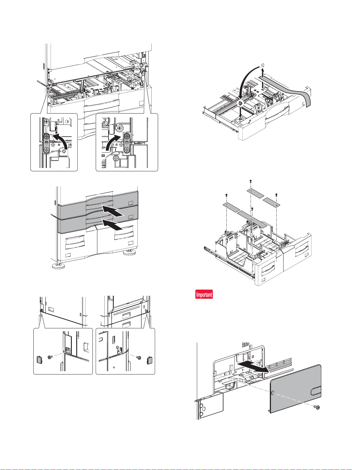
3) Raise the linkage plates on the right and left sides of the front side
of the desk unit, and fix them with the fixing screws included in the
package.
4) Attach the tray 1 and the tray 2.
C. Release the lock
1) Pull out the tray. Turn and remove the fixing material, and remove
the caution sheet.
Attach the removed fixing material to the position shown in the figure for storage.
Close the cassette which was pulled out.
2) Pull out each tandem tray. Turn and remove the fixing material,
and remove the caution sheet.
Attach the removed fixing material to the position shown in the figure for storage.
Close the cassette which was pulled out.
5) Take off the small cover of right and left sides of the main body
rear. And fix them with the fixing screws included in the package.
Return small covers.
Before turning on the power, check to insure that the fixing material of the tray is disengaged. If the power is turned on without disengaging the fixing material, a trouble may be resulted.
D. Connector connection
1) Remove the cover from the rear side of the machine.
MX-4070N MX-DE28 (STAND/500&2100 SHEET PAPER DRAWER) 4 – 2
Page 46
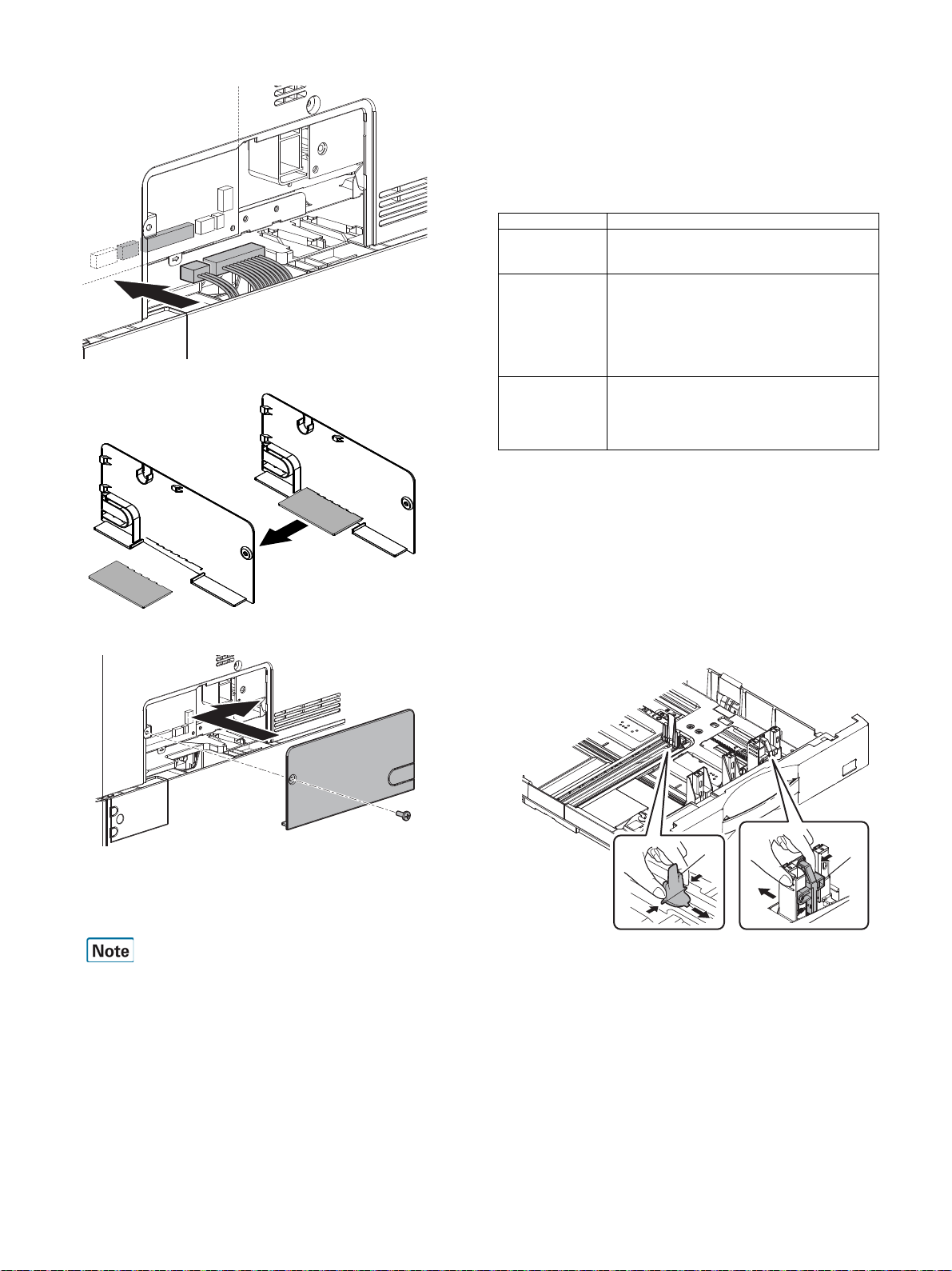
2) Connect the connector.
A
B
3) Separate the base of the cover in nippers.
4) Attach the cover.
F. Tray setup
(1) System Settings
1) Touch [Initial Installation Settings] key on the touch panel.
2) Touch [Tray Settings] for respective setting.Set up paper type,
paper size and Feeding Approved Job for each tray.Touch [Tray
Settings] key to display the list of tray and current settings.
3) Press the respective tray key to display setting screen.The setting
items are as listed below:
Setting Items Description
Type Select the type of paper to be used.
Size Select the size of paper to be used.
Feeding Approved
Job
(2) Tray size setting
a. Tray 2
1) Pull out the paper tray.
Pull out the tray gently until it stops.
Remove the paper loaded into the tray.
2) Adjust guide plates A and B by squeezing their lock levers and
sliding them to match the longitudinal and transversal dimensions
of the paper to be loaded.
The guide plates A and B are slidable. Slide each guide plate
while squeezing its lock lever to adjust to the paper size.
The type of selectable paper type varies depending
on the tray.
The selectable size varies depending on the tray.
The selectable size may be limited depending on the
tray selected in the Type above.
If the appropriate tray is not listed, select [S ize Input]
and designate the size directly. (This is allowed for
Bypass Tray only.)
Select the approved job mode. Disable the feature
do not wish to perform a job using the selected tray .
[Fax] and [Internet Fax] cannot be selected if [Type]
is set to anything other than Plain Paper, Recycle
Paper, Color paper, or User Type.
E. Turn ON the power of the main unit
1) Connect the power plug of the machine to the power outlet, and
turn ON the main power switch and the operation panel power
switch.
For setting the tray size, refer to “Tray size setup” (1-6).
MX-4070N MX-DE28 (STAND/500&2100 SHEET PAPER DRAWER) 4 – 3
Page 47
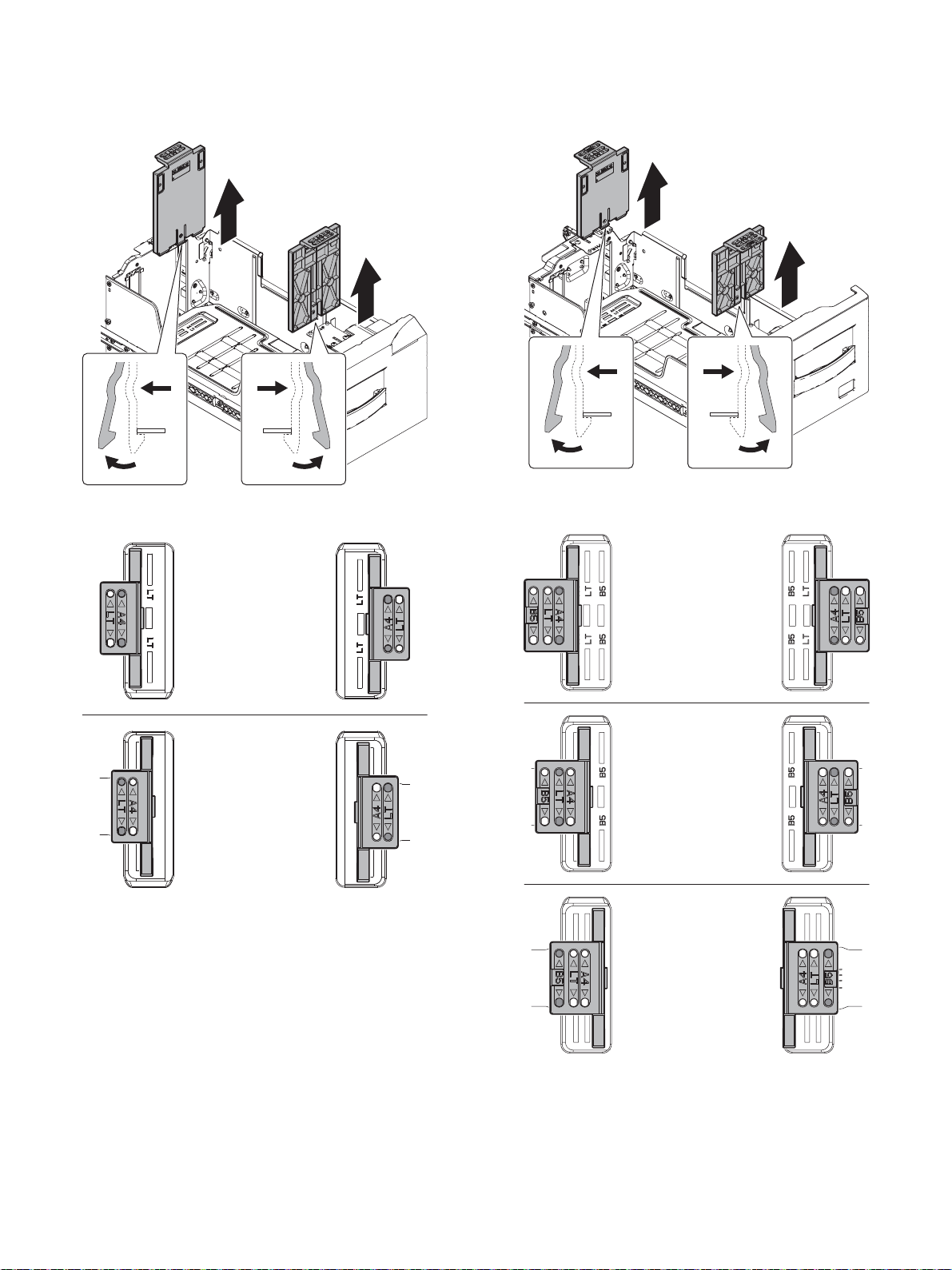
b. Tray 3 (A4/LT)
ĬĬ
ĭ
ĭ
A4
LT
ĬĬ
ĭ
ĭ
A4
LT
B5
1) Pull out the Tandem paper feed tray.
2) Remove the Tandem cassette regulation plate while pressing a
hook.
c. Tray 4 (A4/LT/B5)
1) Pull out the Tandem paper feed tray.
2) Remove the Tandem cassette regulation plate while pressing a
hook.
3) Insert Adjust plate boss to the holes on the Tandem cassette regulation plate for appropriate size.
4) Push the Tandem paper feed tray.
3) Insert Adjust plate boss to the holes on the Tandem cassette regulation plate for appropriate size.
MX-4070N MX-DE28 (STAND/500&2100 SHEET PAPER DRAWER) 4 – 4
Page 48
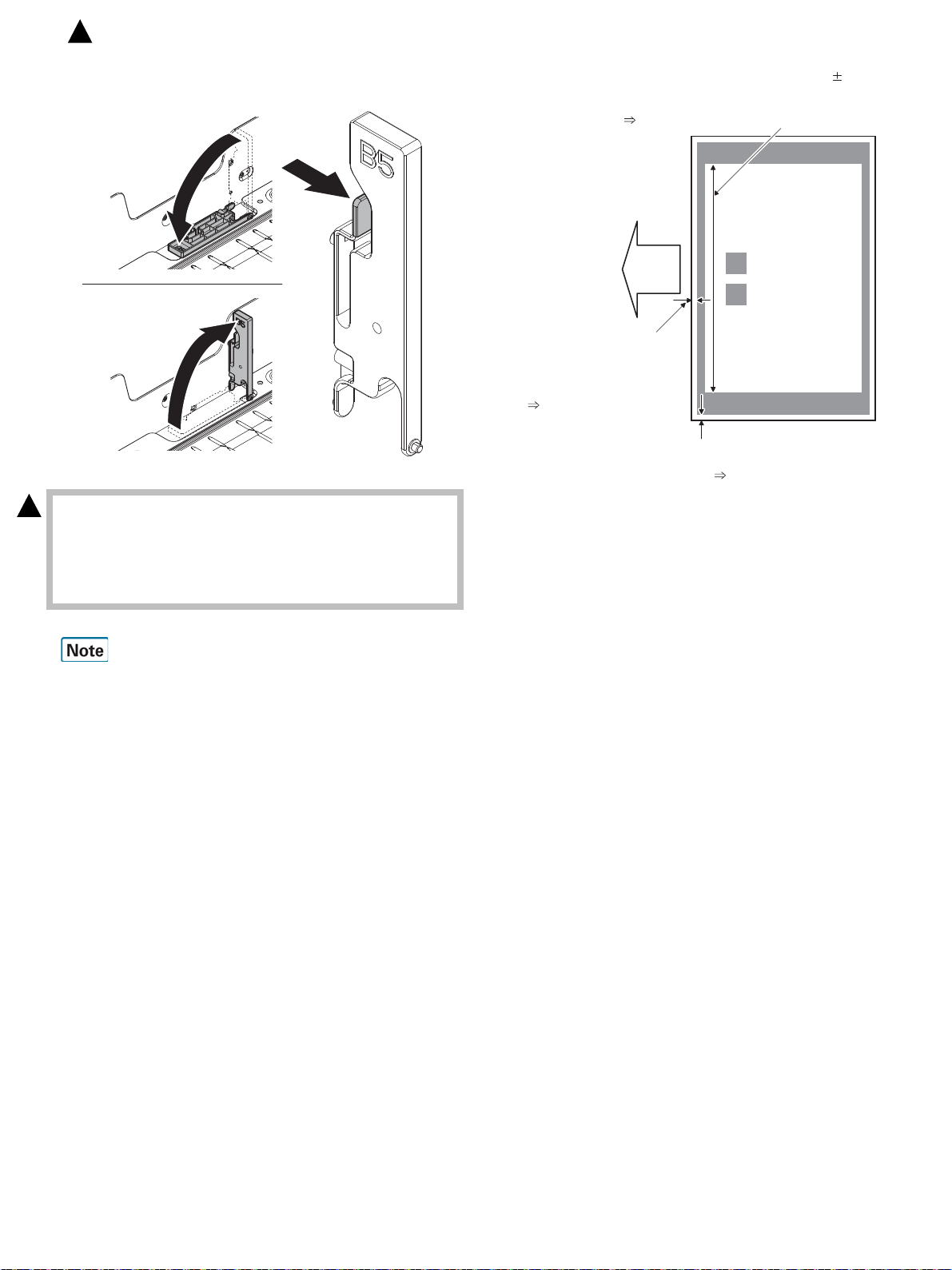
A4 / LT
B5
• Lead edge void amount
(4.0mm terget)
Measure at the center of
paper.
Adjustment value
K : SUB-DSK
Print
lead edge
Main scanning magnification ratio (240 0.5mm)
Measure the dimension near the inner frame line
and the paper lead edge in parallel with the line.
Adjustment value A : BK-MAG
• F side void amount (2.0mm terget)
Measure at a position near the
paper lead edge.
Adjustment value
D : MAIN-CS2
E : MAIN-CS3
F : MAIN-CS4
: ‘16/Feb.
1
4) Lay B5 rear edge regulation plate to set for A4/LT size.Erect the
regulation plate to set for B5 size.
5) Push the Tandem paper feed tray.
(3) Size setting
1
Execute Sim26-2 "Size setting" with the key operations of the main
unit.
1) The size selection menu of the large capacity desk is displayed on
the operation message display.
2) Select a size button to be set on the message screen.
G. Image off-center adjustment
The image lead edge position and the off-center adjustment value of
the desk unit have been set to the average value when shipping from
the factory.
Therefore, this adjustment must be performed only when the judgment
is made to execute it through checking the print image.
* There must be a tray with A4 (LT) paper in it.
1) Enter the Sim. 50-10 mode.
2) Select a paper feed source “3“ (CS2).
3) Set A4 (11 X 8.5) paper on the CS2 paper feed tray.
4) Check to confirm that the inside dimension of the printed half-tone
5) Measure the void area size of the adjustment pattern in the front/
pattern is 2400.5mm.
If the above condition is not satisfied, follow and repeat the proce-
dures of ADJ4A(Service manual) until a satisfactory result is
obtained.
rear frame direction (F side void amount) and that in the transport
direction (Lead edge void amount).
Check to confirm that all the following conditions are satisfied.
Calculation and input procedures of adjustment values
(Example) Lead edge void amount
(1) Measure by visual inspection.
Measurement result: 4.5mm
(2) Calculate the shift amount.
The target value is the specification value (center value) of
3mm.
* For the F side void amount, the target is 2mm.
[4 – 4.5 = -0.5 (mm)]
(3) Calculate the adjustment value.
Subtract 5 from the shift amount of -0.5mm.
* For the shift amount of 0.1mm, the adjustment value is
varied by 1.
When the current value is 50:
[50 – 5 = 45]
(4) Enter the adjustment value for SUB-DSK.
Enter the [45].
6) Enter MAIN-CS2 (F side void) and SUB-DSK (Lead edge void),
and press OK button.
Enter the calculated adjustment values for the shift amount to
MAIN-CS2/SUB-DSK, and press OK button. (The cursor can be
used instead of the button.)
7) After entering the adjustment values, print again and check to
confirm that the avoid amounts are adjusted to the target range.
Perform procedures 4) to 7) for each paper feed tray.
MX-4070N MX-DE28 (STAND/500&2100 SHEET PAPER DRAWER) 4 – 5
Page 49
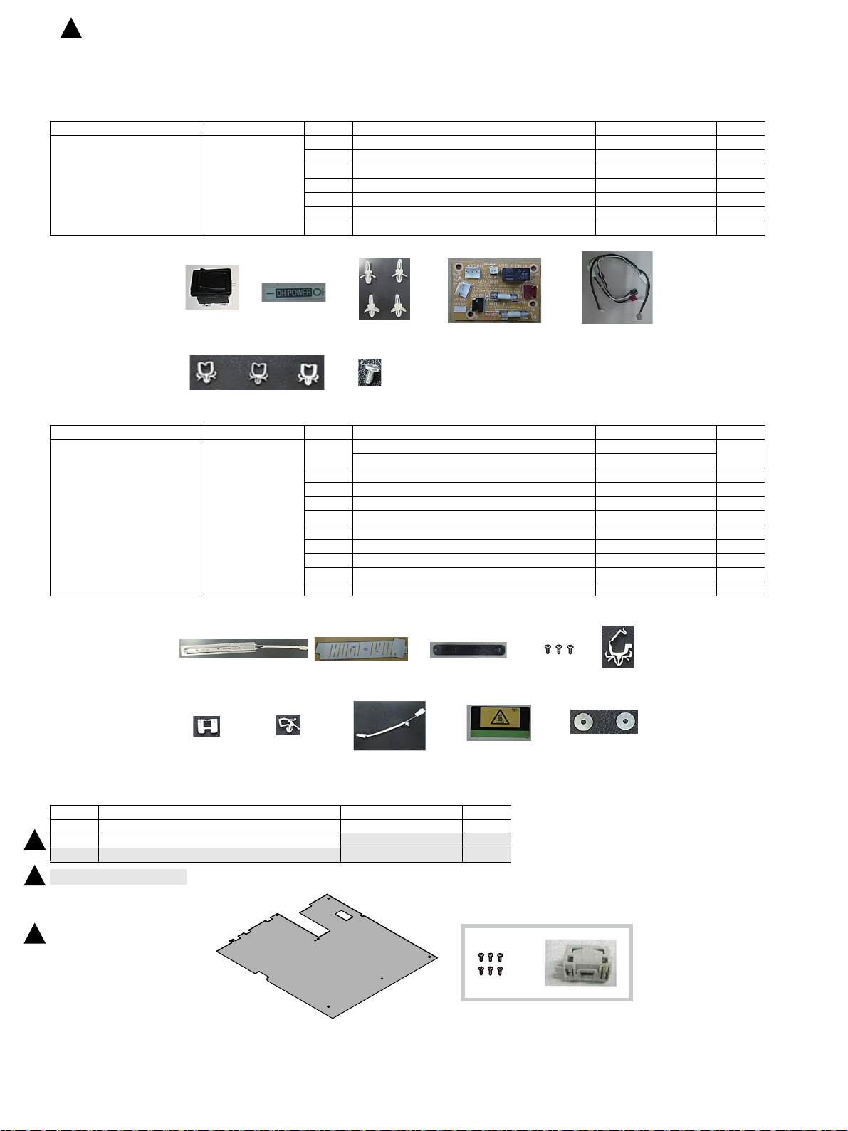
1324
7
5
6
1
8
2345
6
7
9
10
1
23
: ‘16/Sep.
3
MX-4070N
[5] Dehumidifying heater
Service Manual
1. Parts list
Kit name Kit code No. Part name Part code Q'ty
Heater electric component kit DKIT-0454FCZZ 1 Dehumidifier heater control switch QSW-C9294QCZZ 1
2 Dehumidifier heater control switch label TLABZ5256FCZZ 1
3 Support
4 WH PWB CPWBF1935FCE1 1
5 WH harness DHAI-5566FCP1 1
6 Clamp LHLDW2038FCPZ 3
7 Screw XHBS730P06000 1
er LSUPP
0140FCPZ 4
Heater kit DKIT-0455FCZZ
Kit name Kit code No. Part name Part code Q'ty
(100V series)
DKIT-0455FC11
(200V series)
1 Heater (100V series) RHETP0166FCPZ 1
Heater (200V series) RHETP0167FCPZ
2 Heater mounting plate LPLTM9037FCZZ 1
3 Heater mounting plate LHLDZ2598FCZZ 1
4 Screw (M3 x 6 S-tight) XHBS730P06000 3
5 Saddle LHLDW1892FCPZ 1
6 Saddle *1 LHLDW2328FCPZ 1
7 Clamp LHLDW1013FCZZ 1
8 CSS-WH harness DHAI-5567FCP1 1
9 High temperature caution label (200V series only) TLABZ5466FCZ1 1
10 Washer LX-WZ2028SCPZ 2
*1: Not use it for the setting to this model.
These parts are necessary to prepare as service parts before installation.
No. Part name Part code Q'ty
1 LSU plate LPLTM9176FCZZ 1
2 Screw (M3 x 6 P-tight)
3
3* Core RCORF1024MPZZ 1
or Taiwan, South africa.
* F
3
LX-BZ1208FCZZ 6
3
MX-4070N Dehumidifying heater 5 – 1
Page 50
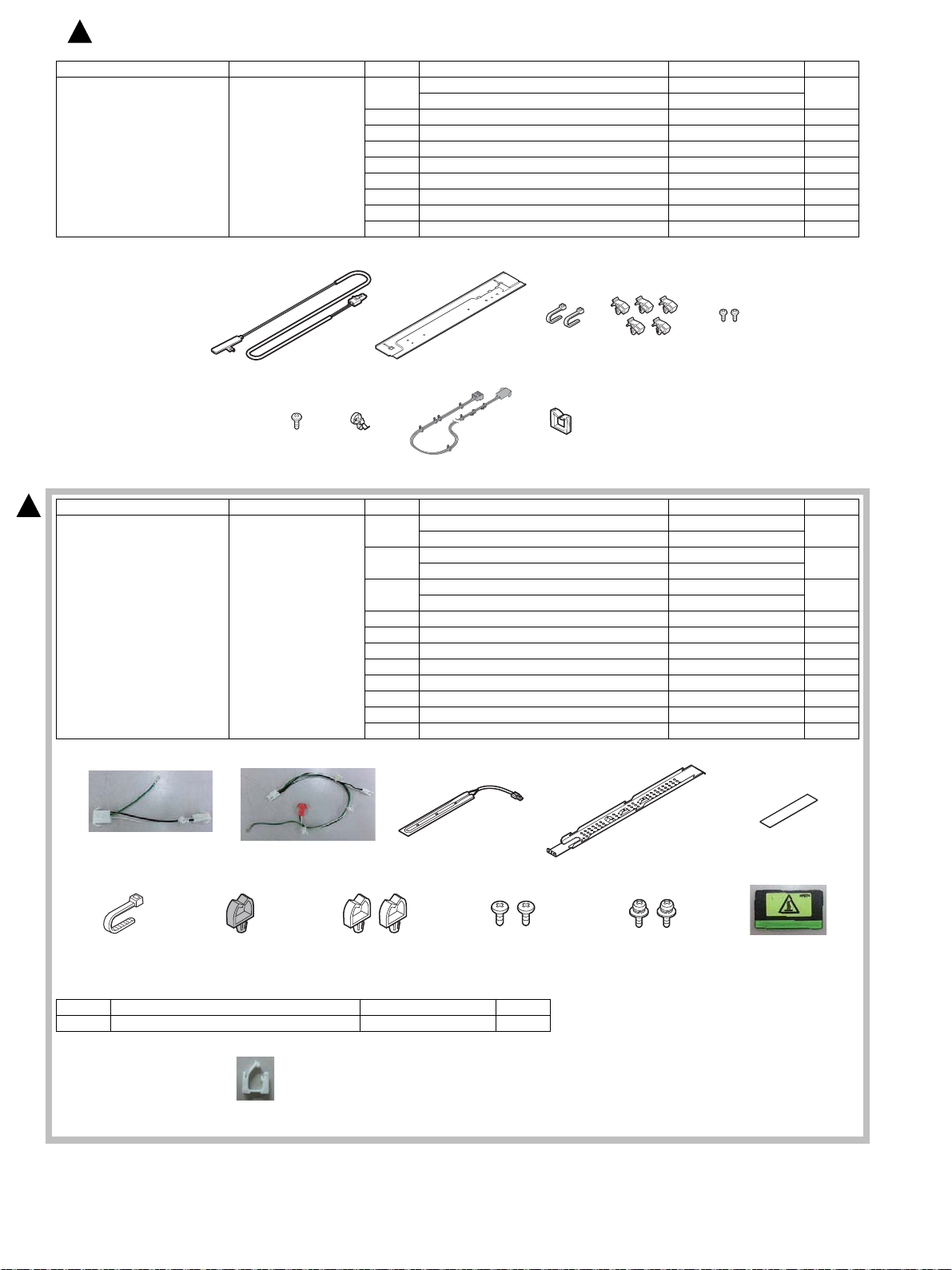
5
67 9
234
8
1
123 4 5
6 7 8 9 10 11
12
: ‘16/Apr.
2
Kit name Kit code No. Part name Part code Q'ty
Scanner heater kit DKIT-0427FC11
(100V series)
DKIT-0427FC12
(200V series)
1 Scanner heater (100V series) RHETP0129FCPZ 1
Scanner heater (200V series) RHETP0130FCPZ
2 Heater fixing plate LPLTM6923FCZZ 1
3 Banding band LBNDJ0013FCZ1 2
4 Clamp LHLDW7011XCZZ 5
5 Screw (M3 x 4 Round-tipped) LX-BZ1041FCZZ 2
6 Screw (M4 x 6 Bind machine screw) XBBS740P06000 1
7 Snap band LBNDJ0043FCZZ 1
8 SCN-WH harness (Not use) DHAI-4702FCPZ 1
9 Edge holder LBSHC0353FCZZ 1
2
One-stage desk heater kit DKIT-0457FCZZ
Kit name Kit code No. Part name Part code Q'ty
(100V series)
DKIT-0457FC11
(200V series)
1 Heater harness (100V series) DHAI-5619FCPZ 1
Heater harness (200V series) DHAI-5672FCPZ
2 Heater harness (100V series) DHAI-5620FCPZ 1
Heater harness (200V series) DHAI-5670FCPZ
3 Heater (100V) RHETP0172FCPZ 1
Heater (200V) RHETP0173FCPZ
4 Heater mounting plate LPLTM9116FCZZ 1
5 Protect sheet PSHEP6815FCZZ 1
6 Binding band LBNDJ0013FCZ1 1
7 Clamp LHLDW1009ACZZ 1
8 Clamp LHLDW1225FCZZ 2
9 Screw (M3×4 S tight bind) XHBS730P04000 2
10 Screw (M4×8) XBPS740P08K00 2
11 Cassette high temperature caution label TLABZ5466FCZ1 1
The parts which are necessary other than a bundling product. *:It is prepared as service parts. Prepare beforehand.
No. Part name Part code Q'ty
10 Edge Saddle (Attach the main body) LHLDW1969FCPZ 1
MX-4070N Dehumidifying heater 5 – 2
Page 51
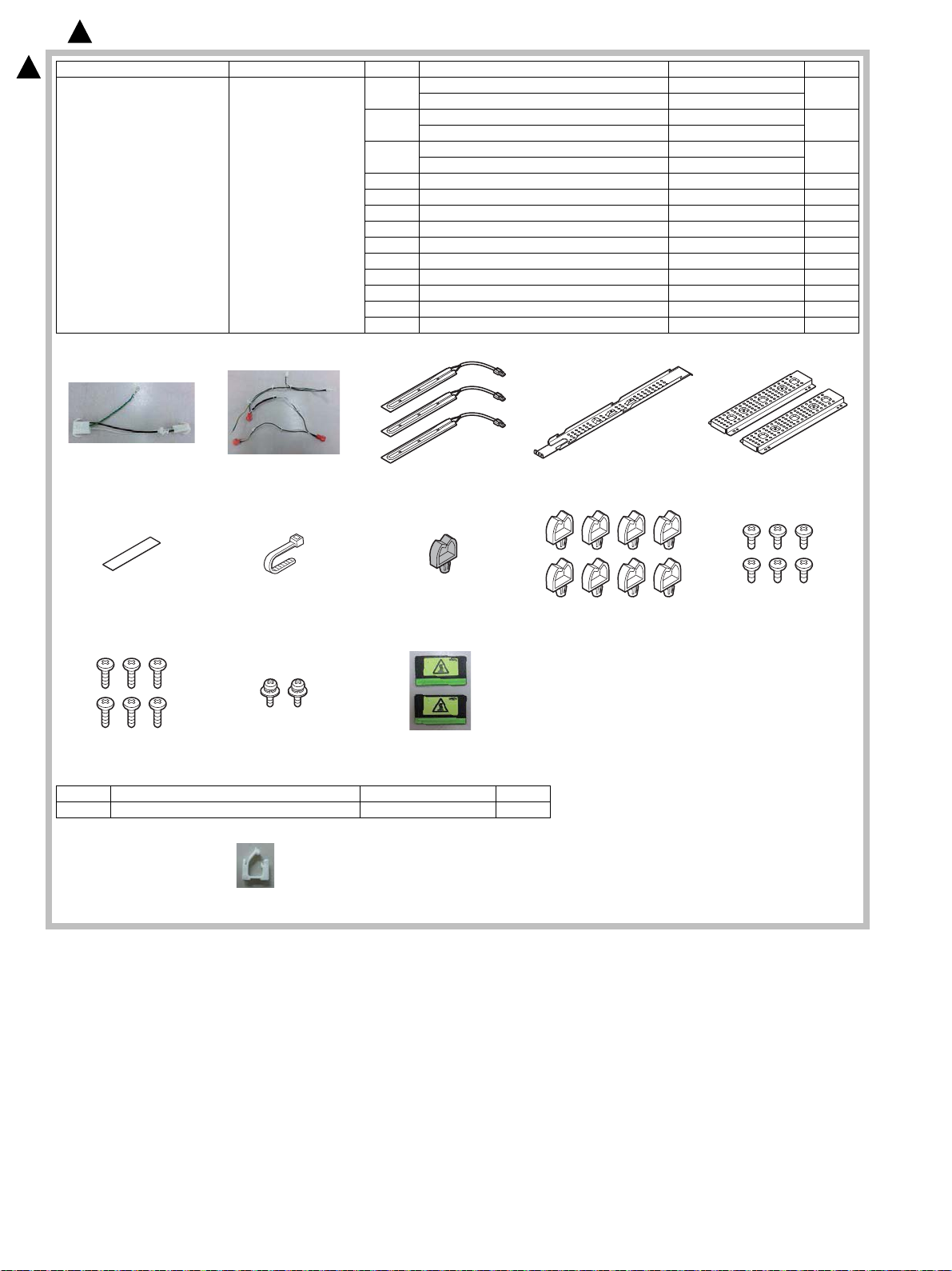
12 3 4 5
67 8 9 10
11
12
13
14
2
: ‘16/Apr.
2
2-/3-stage desk heater kit DKIT-0458FCZZ
Kit name Kit code No. Part name Part code Q'ty
(100V series)
DKIT-0458FC11
(200V series)
1 Heater harness (100V series) DHAI-5619FCPZ 1
Heater harness (200V series) DHAI-5672FCPZ
2 Heater harness (100V series) DHAI-5618FCPZ 1
Heater harness (200V series) DHAI-5671FCPZ
3 Heater (100V) RHETP0172FCPZ 3
Heater (200V) RHETP0173FCPZ
4 Heater mounting plate LPLTM9116FCZZ 1
5 Heater mounting plate LPLTM9118FCZZ 2
6 Protect sheet PSHEP6815FCZZ 1
7 Binding band LBNDJ0013FCZ1 1
8 Clamp LHLDW1009ACZZ 1
9 Clamp LHLDW1225FCZZ 8
10 Screw (M3×4 S tight bind) XHBS730P04000 6
11 Screw (M3×6 S tight bind) XHBS730P06000 6
12 Screw (M4×8) XBPS740P08K00 2
13 Cassette high temperature caution label TLABZ5466FCZ1 2
The parts which are necessary other than a bundling product. *:It is prepared as service parts. Prepare beforehand.
No. Part name Part code Q'ty
16 Edge Saddle (Attach the main body) LHLDW1969FCPZ 1
MX-4070N Dehumidifying heater 5 – 3
Page 52
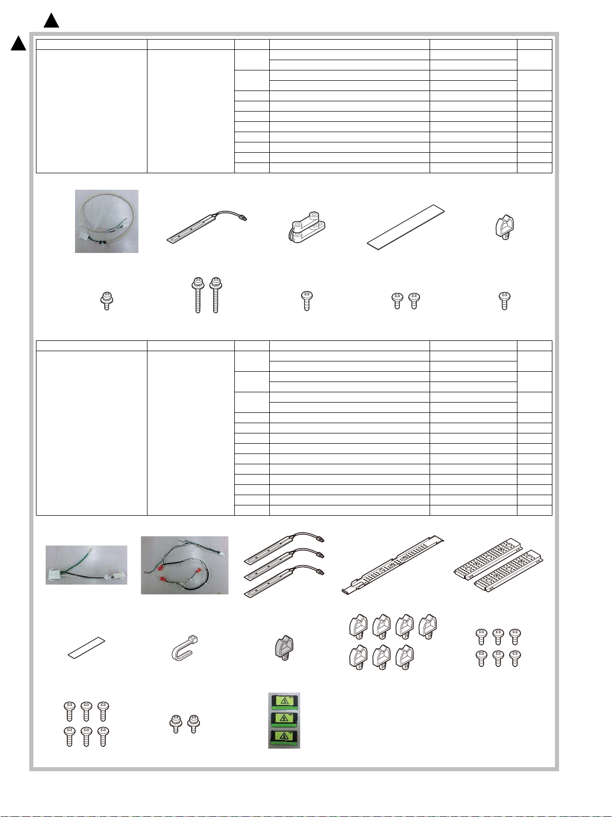
1 2 345
678910
12 3 4 5
67 8 9 10
11
12
13
2
: ‘16/Apr.
2
LCC heater kit DKIT-0460FCZZ
Kit name Kit code No. Part name Part code Q'ty
(100V series)
DKIT-0460FC11
(200V series)
1 Heater harness (100V series) DHAI-5680FCPZ 1
Heater harness (200V series) DHAI-5681FCPZ
2 Heater (100V) RHETP0172FCPZ 1
Heater (200V) RHETP0173FCPZ
3 AC cord fixer LFIX-0016FCZZ 1
4 Protect sheet PFLT-0067FCP1 1
5 Clamp LHLDW1225FCZZ 1
6 Screw (M4×8) XBPS740P08K00 1
7 Screw (M4×28K) XBPS740P28KS0 2
8 Screw (M4×10 P tight bind) XEBS740P10000 1
9 Screw (M3×6 S tight bind) XHBS730P06000 2
10 Screw (M4×8 S tight bind) XHBS740P08000 1
Kit name Kit code No. Part name Part code Q'ty
Tandem desk heater kit DKIT-0459FCZZ
(100V series)
DKIT-0459FC11
(200V series)
1 Heater harness (100V series) DHAI-5619FCPZ 1
Heater harness (200V series) DHAI-5672FCPZ
2 Heater harness (100V series) DHAI-5631FCPZ 1
Heater harness (200V series) DHAI-5673FCPZ
3 Heater (100V) RHETP0172FCPZ 3
Heater (200V) RHETP0173FCPZ
4 Heater mounting plate LPLTM9116FCZZ 1
5 Heater mounting plate LPLTM9118FCZZ 2
6 Protect sheet PSHEP6815FCZZ 1
7 Binding band LBNDJ0013FCZ1 1
8 Clamp LHLDW1009ACZZ 1
9 Clamp LHLDW1225FCZZ 7
10 Screw (M3×4 S tight bind) XHBS730P04000 6
11 Screw (M3×6 S tight bind) XHBS730P06000 6
12 Screw (M4×8) XBPS740P08K00 2
13 Cassette high temperature caution label TLABZ5466FCZ1 3
MX-4070N Dehumidifying heater 5 – 4
Page 53
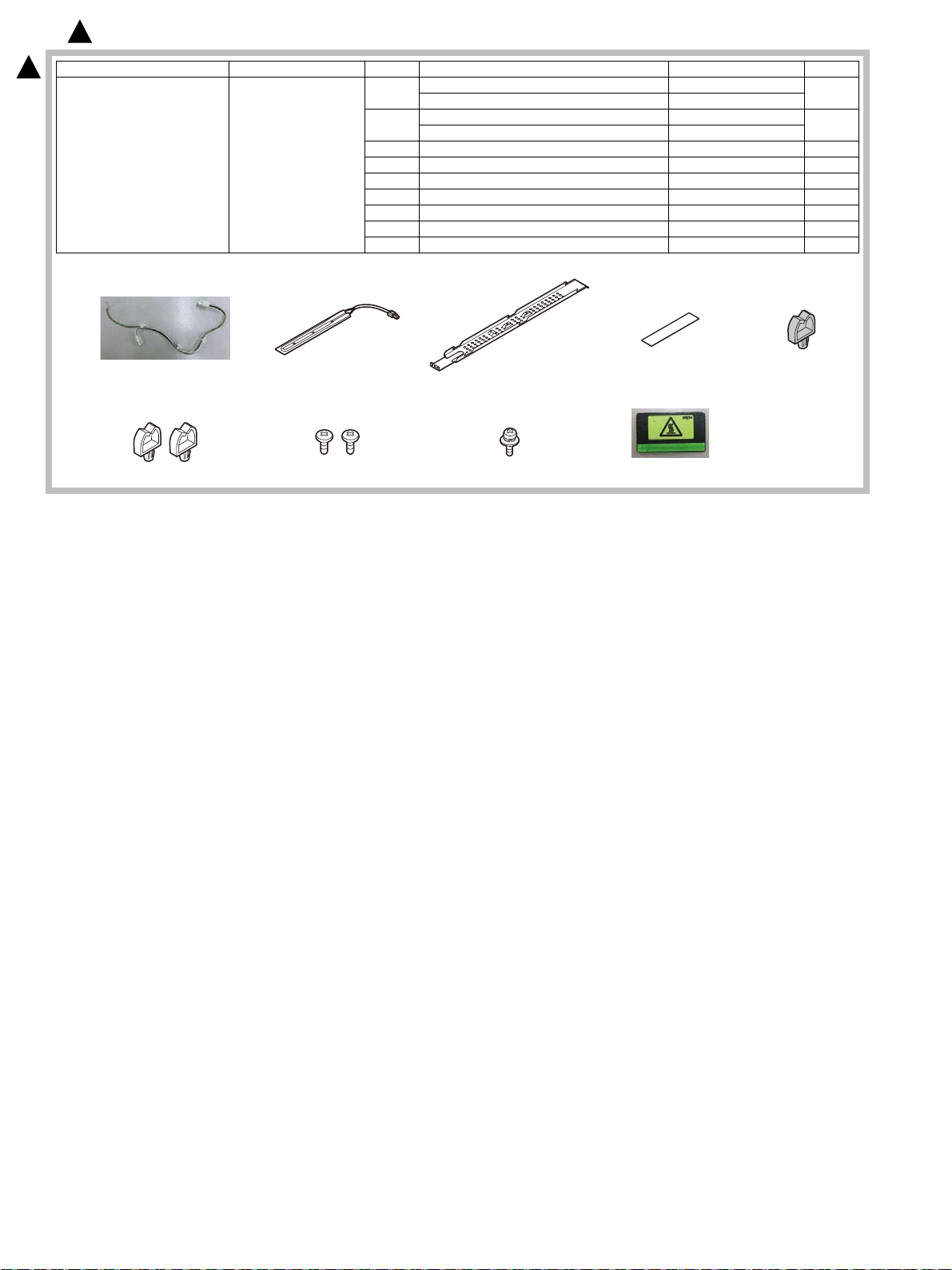
12345
6789
2
: ‘16/Apr.
2
One-stage short desk heater kit DKIT-0462FCZZ
Kit name Kit code No. Part name Part code Q'ty
(100V series)
DKIT-0462FC11
(200V series)
1 Heater harness (100V series) DHAI-5614FCPZ 1
Heater harness (200V series) DHAI-5691FCPZ
2 Heater (100V) RHETP0172FCPZ 1
Heater (200V) RHETP0173FCPZ
3 Heater mounting plate LPLTM9116FCZZ 1
4 Protect sheet PSHEP6815FCZZ 1
5 Clamp LHLDW1009ACZZ 1
6 Clamp LHLDW1225FCZZ 2
7 Screw (M3×4 S tight bind) XHBS730P04000 2
8 Screw (M4×8) XBPS740P08K00 1
9 Cassette high temperature caution label TLABZ5466FCZ1 1
MX-4070N Dehumidifying heater 5 – 5
Page 54
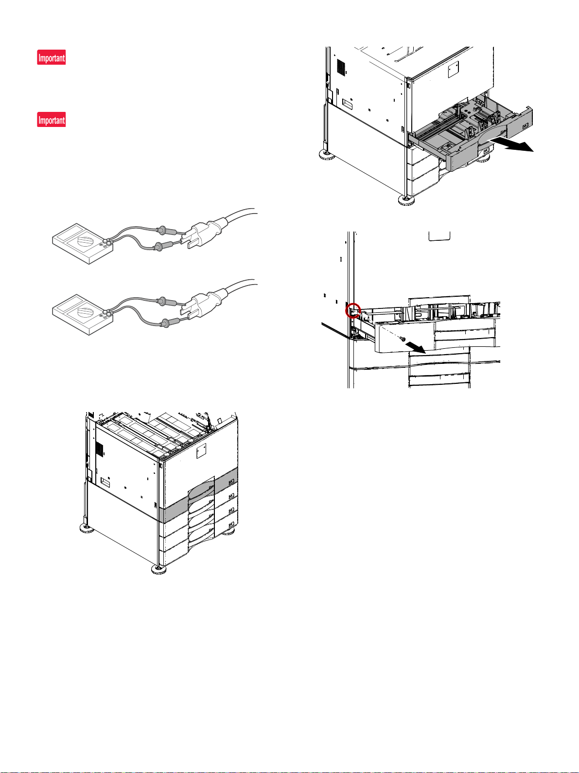
2. Installation
Before installation, be sure to turn both the operation and main power
switches off and disconnect the power plug from the power outlet.
Make double sure that the data lamp on the operation panel does not
light up or blink when performing installation.
Operation check after installation
1) Turn on the dehumidifier heater switch.
2) Measure the resistance value between the earth terminal and the
AC terminal (L side), and between the earth terminal and AC terminal (N side) with the circuit tester, and confirm they are not
short-circuited.
2) Pull the 1casette.
3) Remove the screw of the left cabinet.
3) When not using the dehumidifier heater after checking, turn off the
dehumidifier heater switch.
A. Change the LSU Baseplate
(1) External fixture removal
1) Remove the left cabinet.
MX-4070N Dehumidifying heater 5 – 6
Page 55
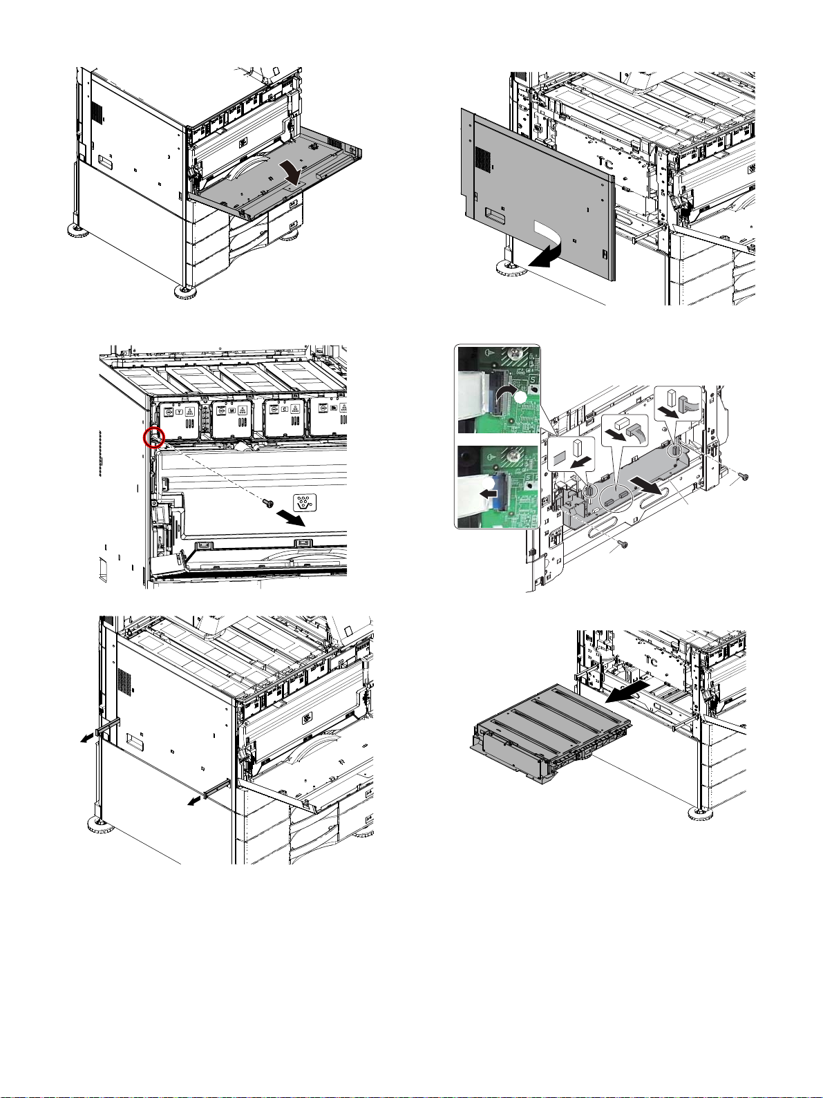
4) Open the front cover.
ĭ
ĭ
Į
Ĭ
Ĭ
Ĭ
Ĭ
ĭ
7) Remove the left cabinet lower.
5) Remove the screw of the left cabinet.
6) Pull the hand lift.
8) Remove the connector and remove the screw. And pull the LSU.
9) Remove the LSU.
MX-4070N Dehumidifying heater 5 – 7
Page 56
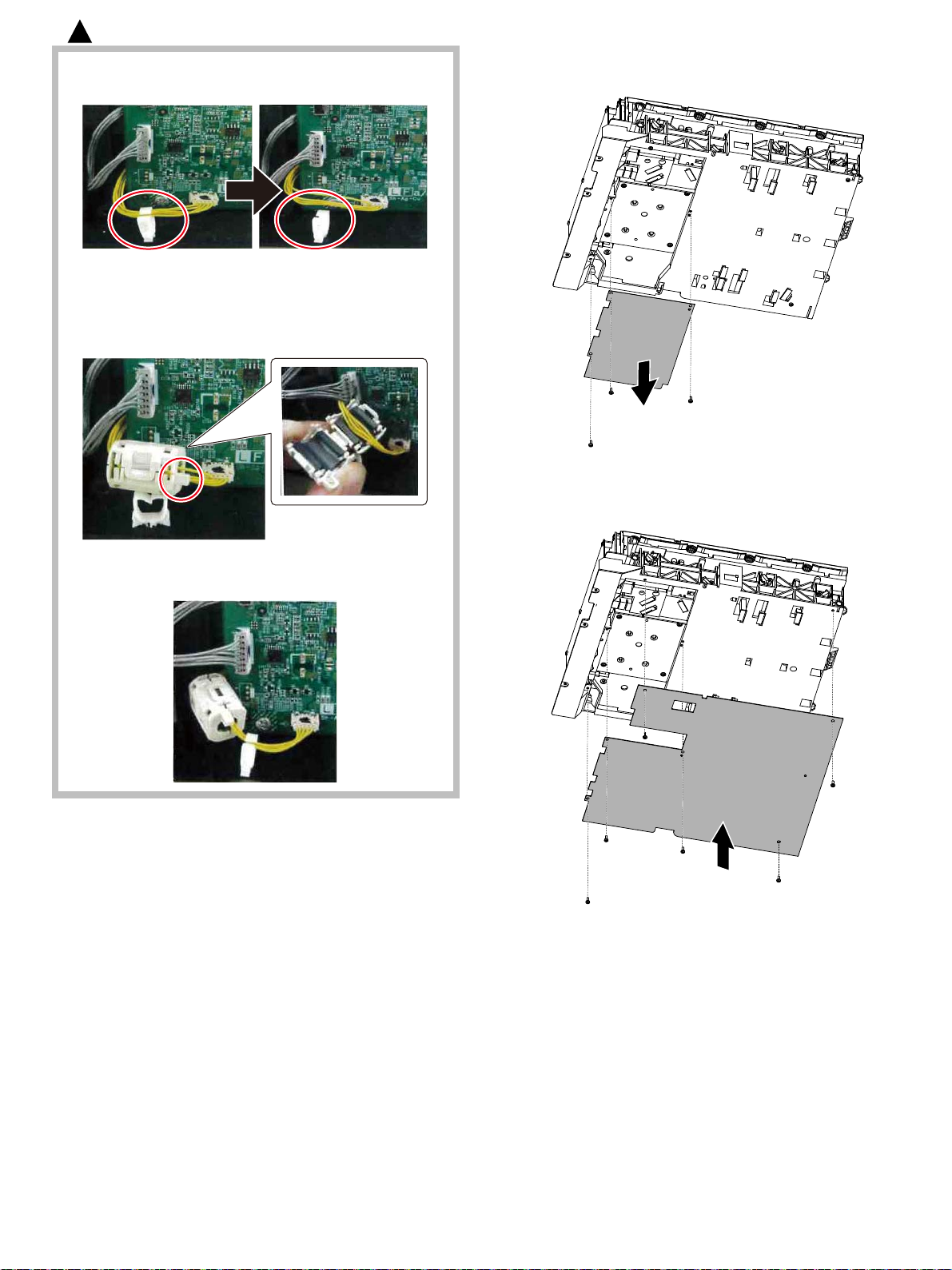
: ‘16/Sep.
3
For Taiwan, South africa.
9-a Remove the harness.
9-b Install the core to the harness. Be aware of the direction
of the core.
Protrusions on the core should be placed in the right
direction.
10) Remove the dark sheet from the LSU.
11) Add the LSU plate to the LSU.
9-c Return the harness to the original position.
MX-4070N Dehumidifying heater 5 – 8
Page 57

12) Re-attach the LSU.
ĭ
ĭ
Į
Ĭ
Ĭ
ĭ
Į
Į
13) Attach the LSU. Secure it with the screw and connect the connectors.
15) Secure the left cabinet cover with the screw.
16) Close the front cover.
14) Attach the cabinet lower.
17) Secure the left cabinet cover with the screw.
MX-4070N Dehumidifying heater 5 – 9
Page 58
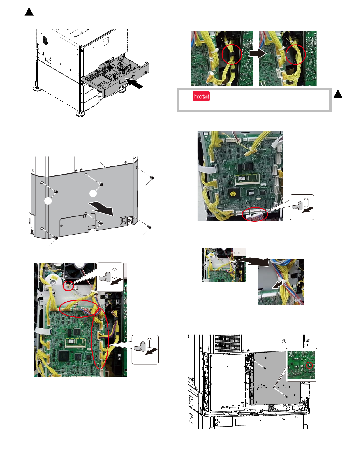
Ĭ
Ĭ
Ĭ
Ĭ
Ĭ
Ĭ
ĭ
: ‘16/Apr.
2
18) Close the 1 cassette.
B. Heater electric component kit installation
(1) WH PWB attachment
1) Remove the rear cabinet.
3) Remove the harness form the guide.
2
Attach the harness to the guide when attach the connector.
4) Disconnect the connector.
2) Disconnect the connector.
5) Remove the harness form the saddle.
6) Remove the three screws.
MX-4070N Dehumidifying heater 5 – 10
Page 59
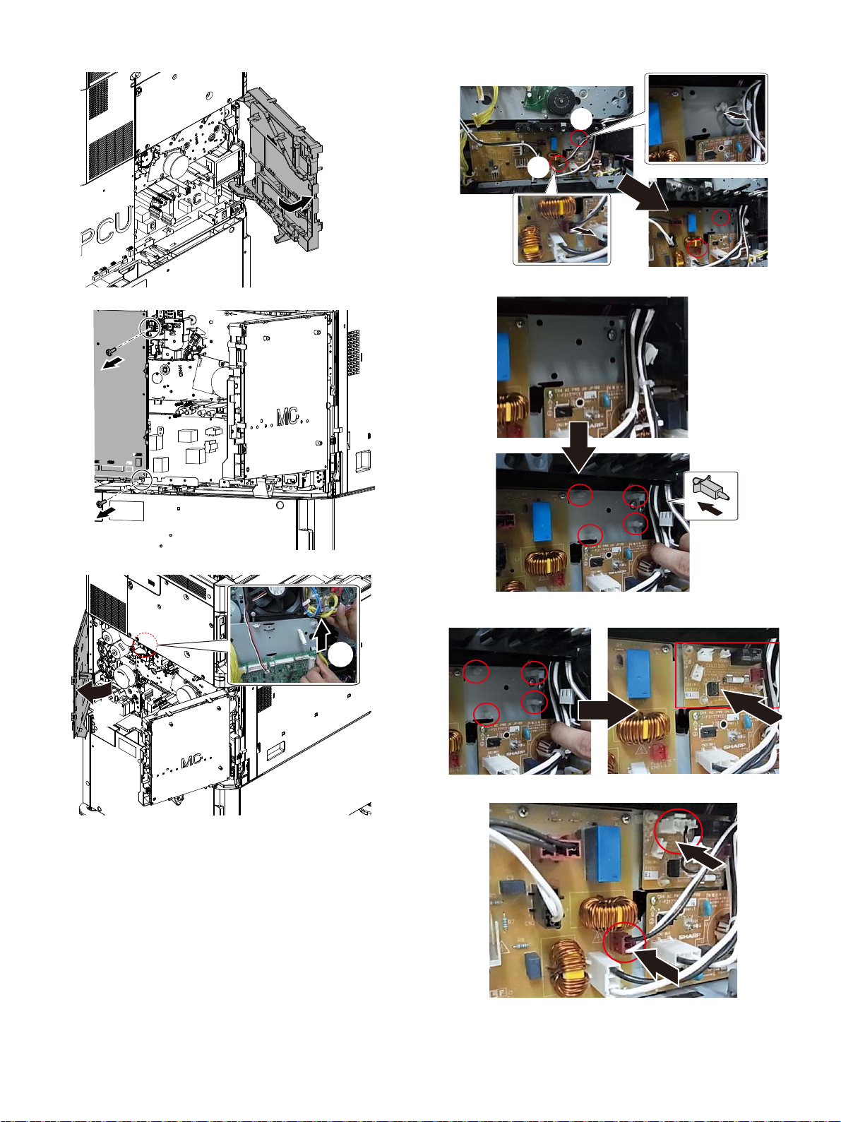
7) Open the MC cover.
Ĭ
ĭ
Ĭ
ĭ
10) Remove the snap band. And remove the connecter.
8) Remove the two screws.
9) Open the PCU cover.
11) Attach the 4 supporters.
12) Attach the WH PWB.
13) Re-connect the connector.
MX-4070N Dehumidifying heater 5 – 11
Page 60
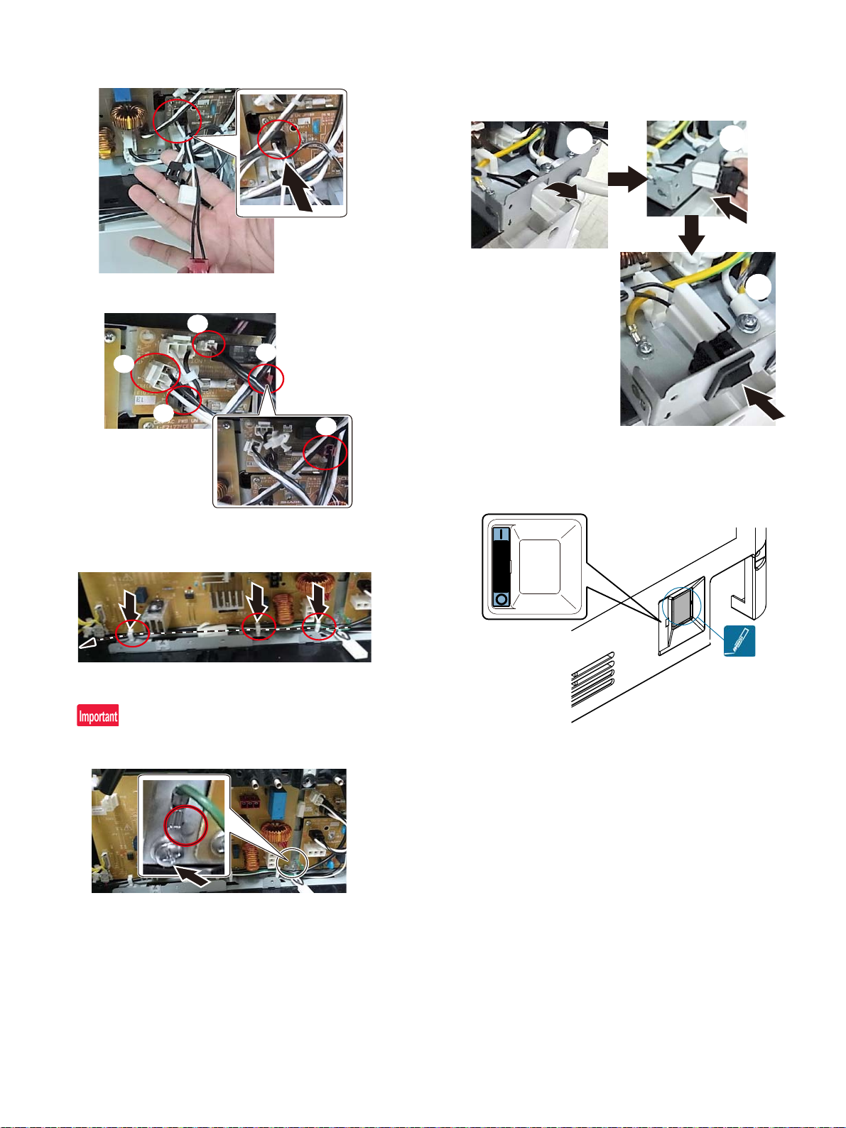
(2) WH harness connection
Ĭ
ĭ
Į
į
į
Ĭ
ĭ
Į
DH POWER
1) Connect the connector on AC PWB.
2) Connect the connector on WH PWB.
(3) Dehumidifier heater control switch attachment
1) Connect the WH harness to the dehumidifier heater control
switch.(Connect to the terminal on the AC cord side.) And attach
the dehumidifier heater control switch.
2) Cut away the dehumidifier heater control switch section on the
rear cabinet.
Attach the dehumidifier heater control switch label to the rear cabinet.
3) Attach the three clumps to the frame. And pass it through the
clamp.
4) Attach the earth wire.
The boss of the rotation stopper come to the right side of the terminal.
MX-4070N Dehumidifying heater 5 – 12
Page 61
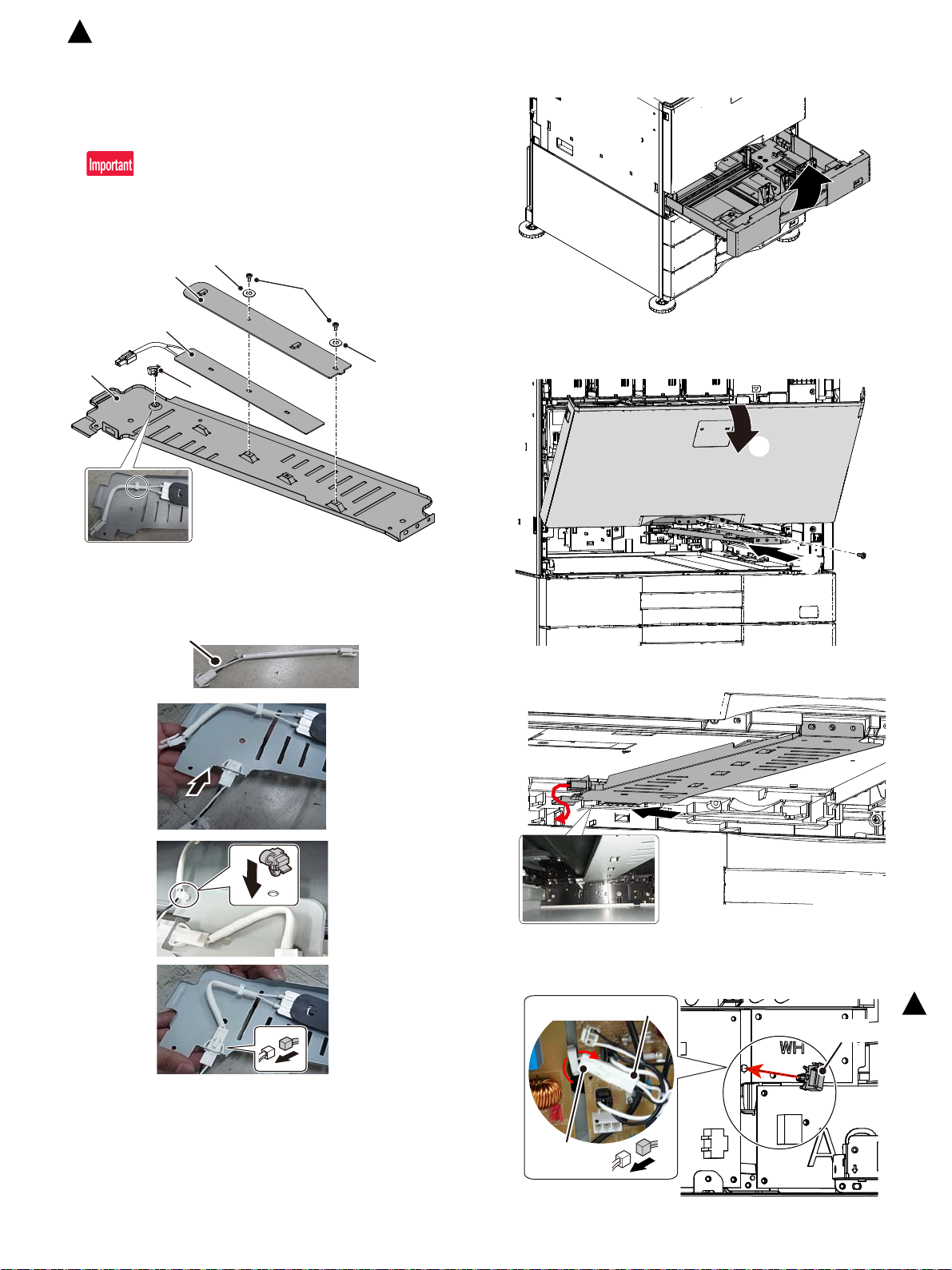
No.1
No.2
No.3
No.7
No.4
No.10
No.10
No.8
Ĭ
ĭ
No.5
ACWH harness
CSS-WH
harness
: ‘16/Apr.
2
C. Heater kit installation
(1) Heater unit assembly
1) Attach the heater to the heater mounting plate and secure it with
the screw (M3 x 6 S-tight).
Attach the clamp, and fix the harness to the clamp.
The direction where the heater is attached to do the indication
side of voltage / electricity specifications listed in a heater in the
bottom.
(2) Heater unit attachment
1) Remove the tray 1.
2) Open the front cover. Attach the heater unit to the main unit, and
secure it with the screw (M4 x 10 P-tight).
2) Attach the CSS-WH harness to the heater mounting plate, and
connect the harness of the dehumidifier heater.
Pass the harness of the heater through the hole on the main unit
frame.
3) Attach the wire saddle to the mein frame. Pass the CCS-WH harness through the wire saddle. Connect the CCS-WH harness to
the AC-WH harness.
2
MX-4070N Dehumidifying heater 5 – 13
Page 62
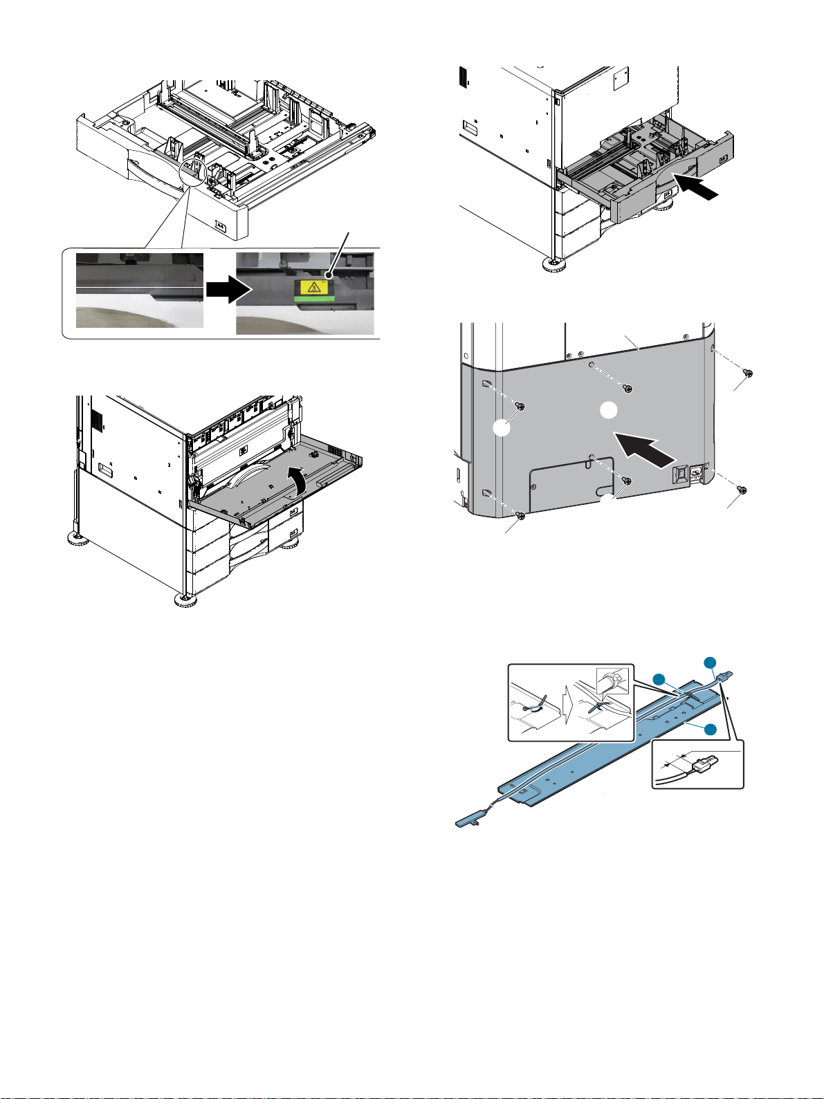
4) Attach the High temperature caution label to the casette 1. (Only
No.9
ĭ
ĭ
Ĭ
ĭ
ĭ
ĭ
ĭ
3
᳸OO
2
1
200V series.)
(3) External fixture attachment
1) Close the front cover.
2) Install the casette 1 to main body.
3) Attach the rear cabinet.
D. Scanner heater kit installation
(1) Scanner heater unit assembly
1) Secure the marking position on the harness of the scanner heater
to the heater fixing plate with the banding band.
2) Extend the harness, and secure the other position of it with banding band.
MX-4070N Dehumidifying heater 5 – 14
Page 63
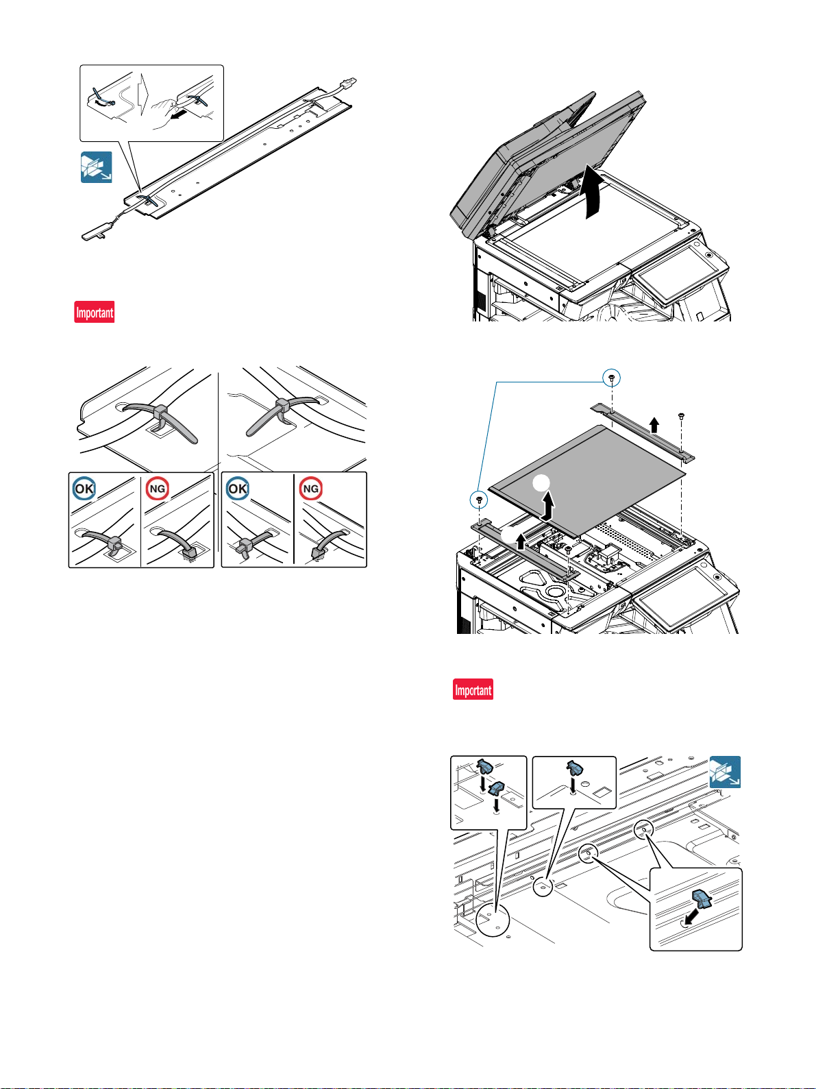
3) Tighten the snap band and cut its tip to approx. 5 mm or less.
DSPFtypeonly
Ĭ
ĭ
Į
Slide the banding band head to the square hole (Part that is
enclosed by the mark).
(2) Table glass removal
1) Open the SPF.
The banding band head and cut tip must not protrude behind the
heater fixing plate.
2) Remove the glass holder. Remove the table glass and the SPF
glass.
(3) Scanner heater unit attachment
1) Attach the clamp to the scanner frame.
When installing, be careful to prevent damage of the wire.
MX-4070N Dehumidifying heater 5 – 15
Page 64
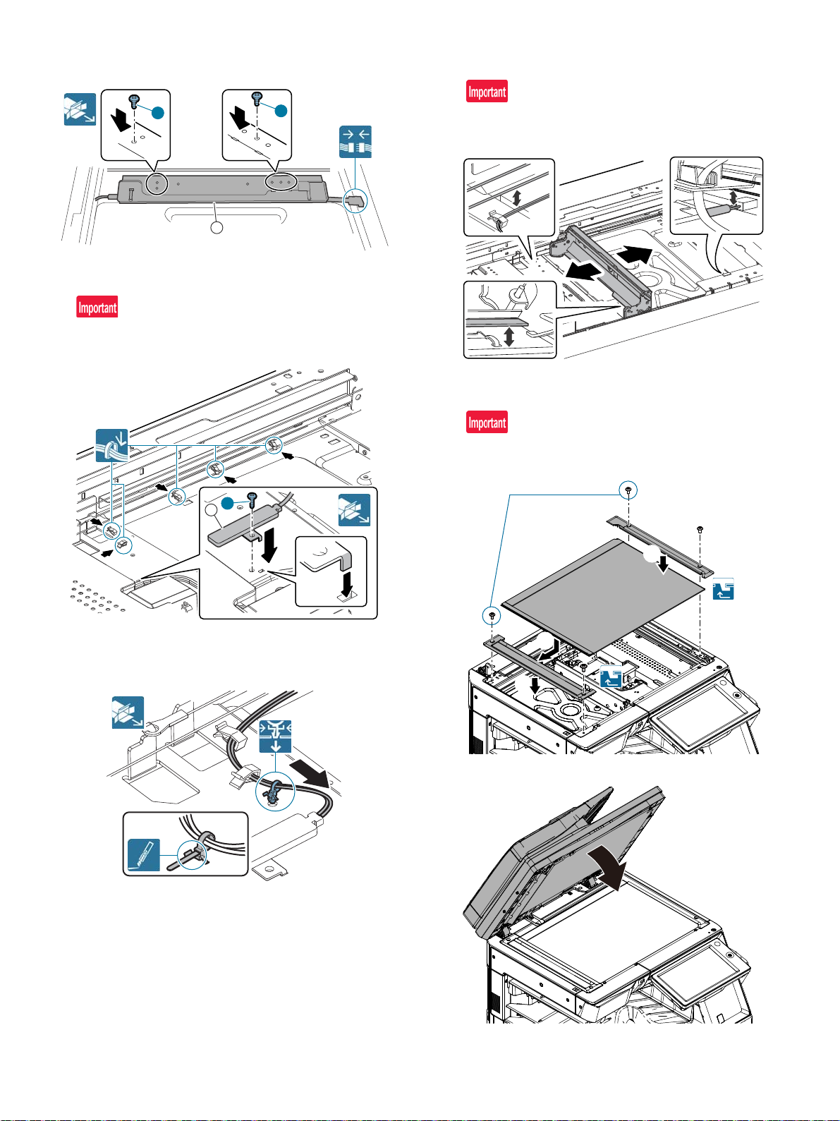
2) Connect the harness of the scanner heater. Attach the scanner
2
2
1
1
2
DSPFtypeonly
Ĭ
ĭ
Į
heater unit, and fixing the screw (M3 x 4 Round-tipped).
3) Attach the scanner heater and secure it with the screw (M4 x 6
Bind machine screw). Pass the harness through the clamp.
The convex part of the scanner heater must be inserted into the
hole of the scanner frame.
5) Move the lamp unit by hand and check that it move smoothly in all
movable area.
Check that there is no interference of the harness of the scanner
heater in the wire and the 2/3 mirror unit.
(4) Table glass attachment
1) Attach the SPF glass and the table glass. Attach the glass holder.
When installing the glass holder, slide it to the left until it clicks,
and fix it with screws.
4) Tighten the loose scanner heater harness by pulling it in the arrow
direction and secure it with the snap band then cut its tip to
approx. 5 mm or less.
2) Close the SPF.
MX-4070N Dehumidifying heater 5 – 16
Page 65
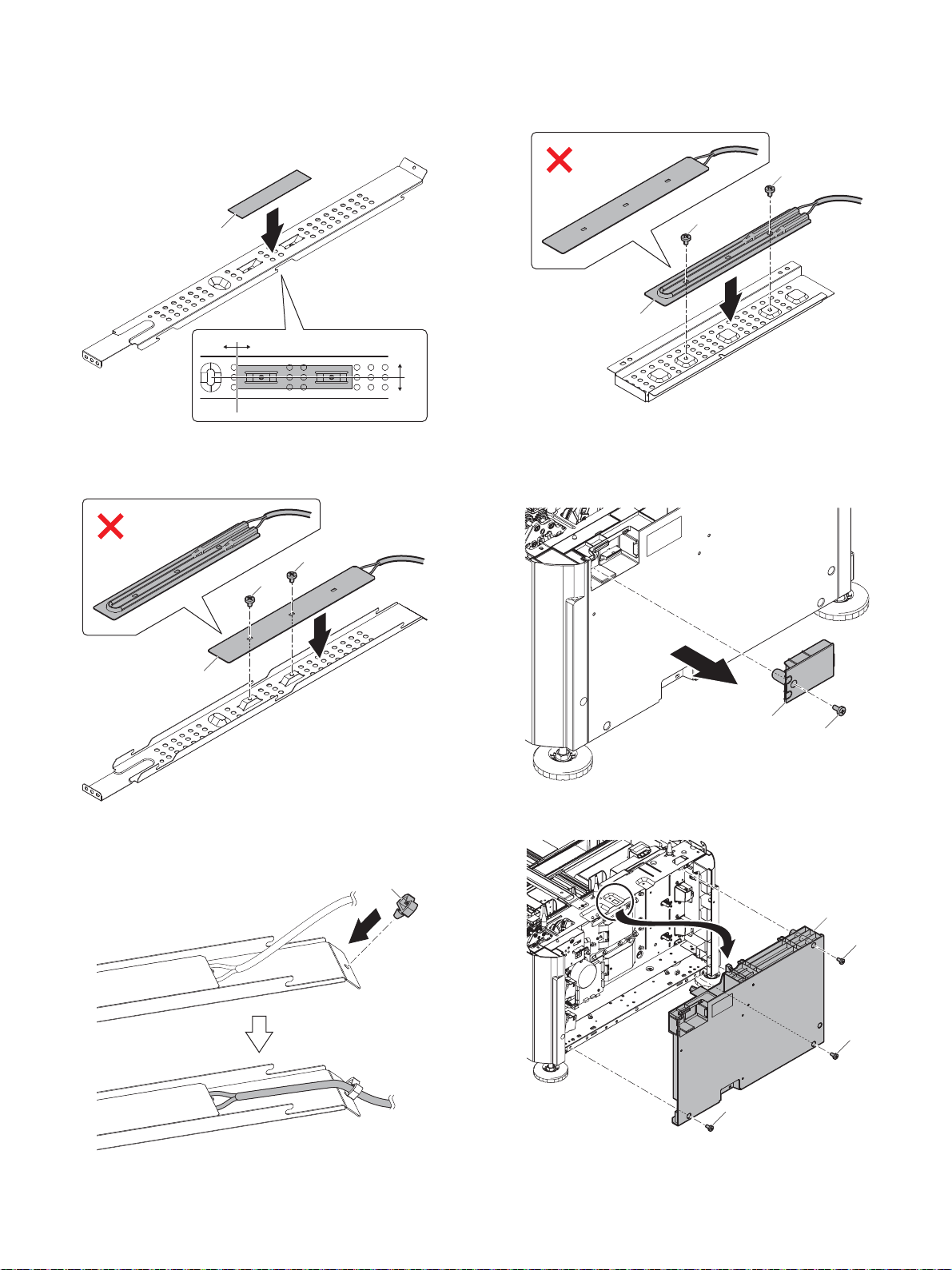
E. Desk heater kit installation
±1mm ±1mm
Ĭ
Ĭ
ĭ
ĭ
Ĭ
Ĭ
ĭ
ĭ
Ĭ
ĭ
Ĭ
Ĭ
Ĭ
ĭ
(1) Tray 2 heater unit assembly
1) Clean the label attaching surface of the desk heater mount plate
upper by the alcohol and attach the desk heater protection sheet.
(2) Tray 3/4 heater unit assembly
1) Attach the desk heater to the heater mounting plate, and fix it with
a screw (M3 x 4 S tight bind).
2) Attach the desk heater to the heater mounting plate, and fix it with
a screw (M3 x 4 S tight bind).
3) Attach the mini clamp on the desk heater mount plate upper and
pass the heater harness through it.
(3) Connector cover, rear cabinet and right rear cabinet
removal
1) Remove the Connector cover.
2) Remove the rear cabinet.
MX-4070N Dehumidifying heater 5 – 17
Page 66
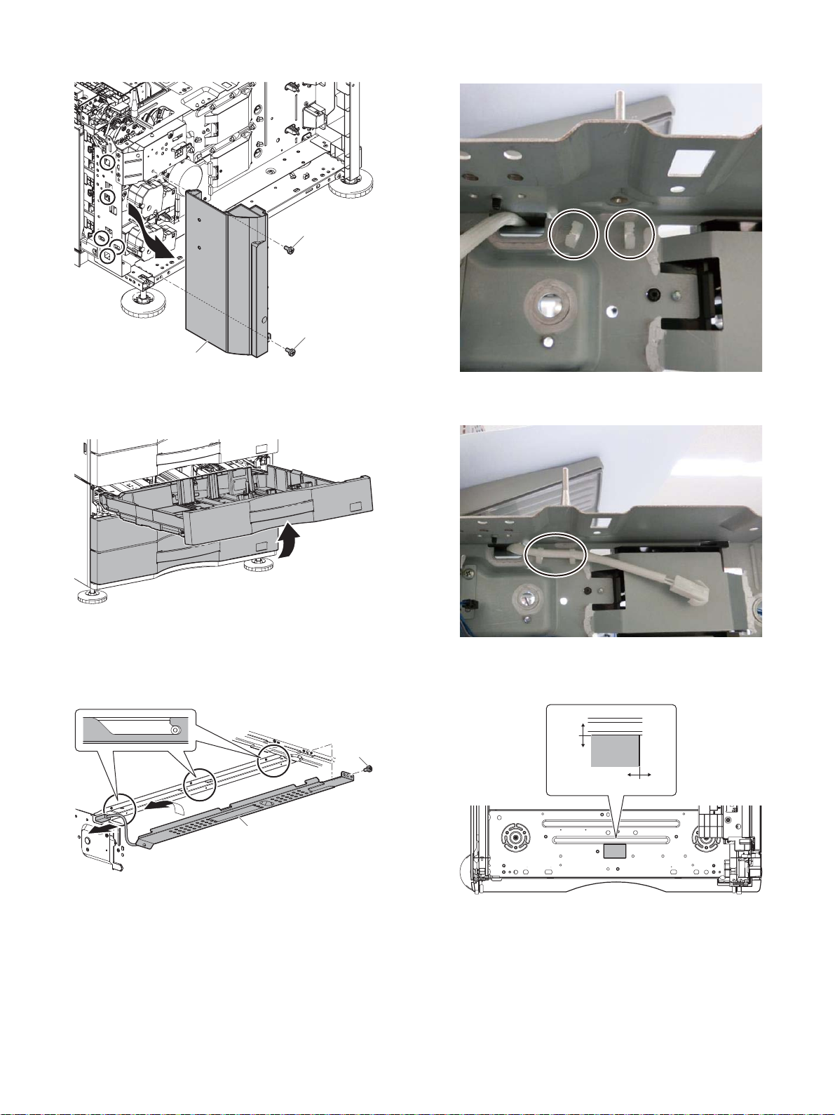
3) Remove the right rear cabinet.
Ĭ
Ĭ
ĭ
Ĭ
ĭ
0mm
0mm
0.5mm
0.5mm
2) Attach the mini clamp on the rear frame.
(4) Paper feed tray removal
1) Pull out the paper feed tray, and lift it to remove.
(5) Tray 2 heater unit attachment
1) Pass the harness of the heater unit for the tray 2 through the hole
in the frame. Attach the heater unit for the tray 2 to the frame, and
fix it with a screw (M3 x 6 S tight bind).
3) Pass the heater harness through the mini clamp.
4) Clean the label attaching surface of the desk bottom by the alcohol and affix the high temperature warning label onto the frame.
MX-4070N Dehumidifying heater 5 – 18
Page 67
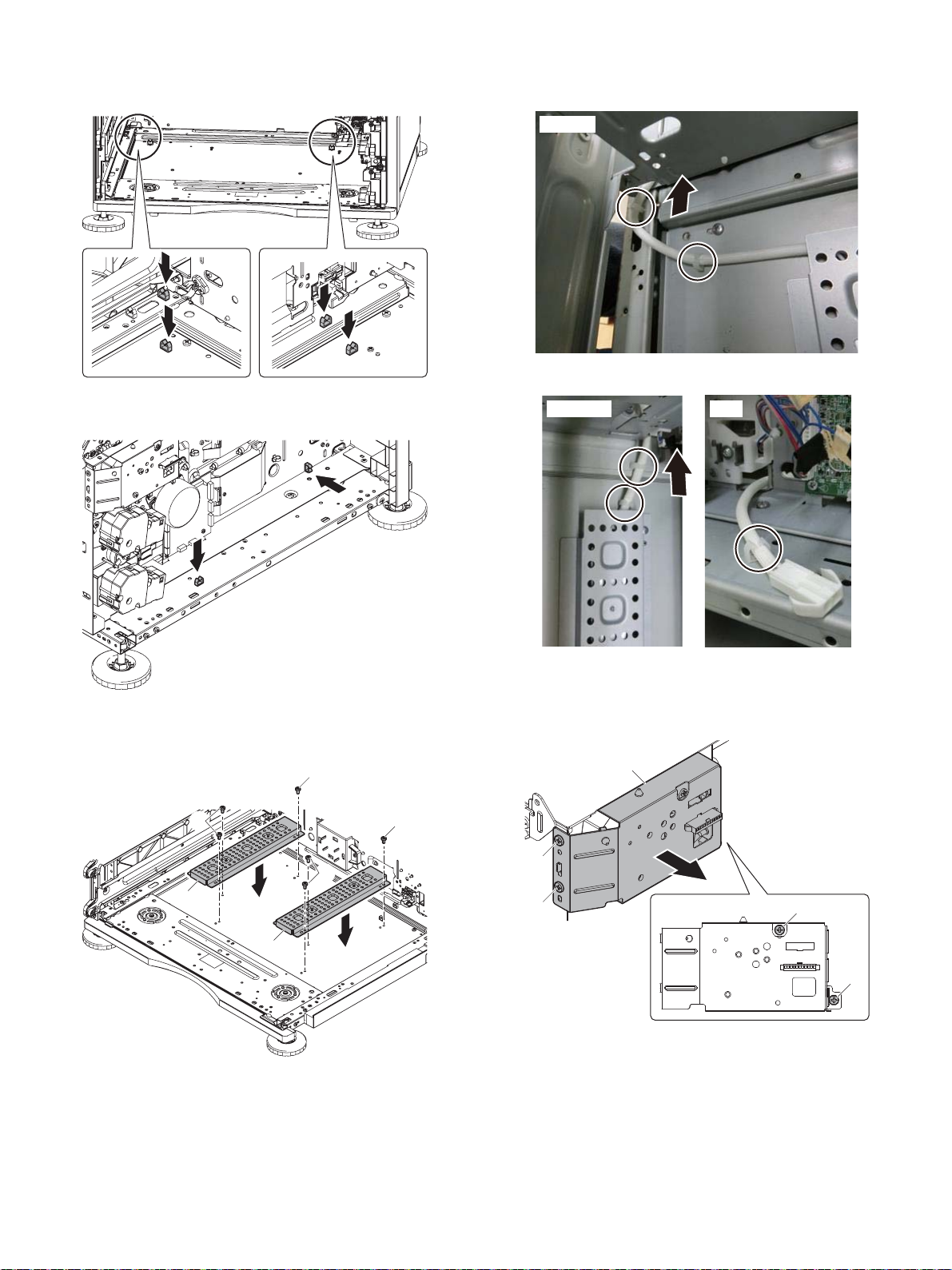
(6) Tray 3/4 heater unit attachment
Ĭ
Ĭ
ĭ
ĭ
ĭ
ĭ
Left side
Right side Rear
Ĭ
Ĭ
ĭ
ĭ
Į
1) Attach the four mini clamps on the desk bottom.
2) Attach the two mini clamps on the rear frame.
4) Pass the harness of the heater unit for the tray 3/4 through the
hole in the frame, and pass it through the clamp.
3) Attach the heater unit for the tray 3/4 to the frame, and fix it with a
screw (M3 x 6 S tight bind).
(7) Heater harness 2 attachment
1) Remove the desk LCC connector fixing plate.
MX-4070N Dehumidifying heater 5 – 19
Page 68
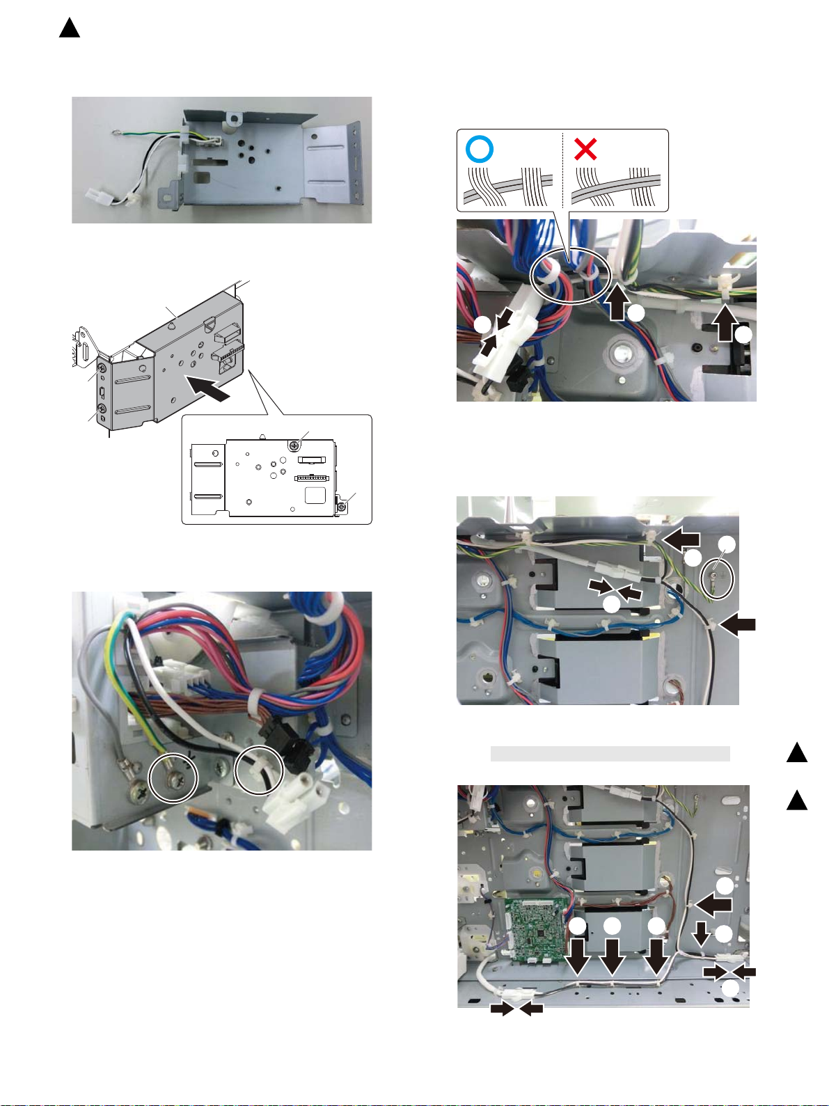
Į
Į
ĭ
ĭ
Ĭ
Ĭ
ĭ
Į
Ĭ
ĭ
Į
į
ĭĮį
İ
ı
ı
Ĭ
: ‘16/Apr.
2
2) Attach the heater harness 2 to the desk LCC connector fixing
plate.
3) Attach the desk LCC connector fixing plate.
(8) Heater harness attachment
1) Attach the reusable band of the heater harness and connect the
connector of the heater harness to the connector of the heater
harness 2.
2) Attach the reusable band of the heater harness and connect the
connector of the heater harness to the connector of the tray 2
heater. Then, attach the circle terminal of heater harness with the
two screws (M4x8)
4) Attach the circle terminal of heater harness 2 with the two screws
(M4x8) and attach the heater frame 2 with the reusable band.
3) Attach the reusable band of the heater harness and connect the
connector of the heater harness to the connector of the tray 3/4
heater, and pass the heater harness through the clamp.
2
2
MX-4070N Dehumidifying heater 5 – 20
Page 69
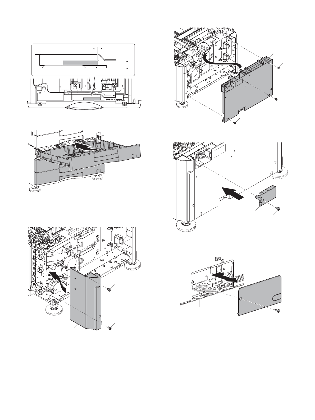
(9) Paper feed tray attachment
0mm0.5mm
0mm
0.5mm
ĭ
ĭ
Ĭ
ĭ
ĭ
ĭ
Ĭ
ĭ
Ĭ
1) Clean the label attaching surface of the tray 2 by the alcohol and
affix the high temperature warning label onto the frame.
2) Attach the paper feed tray.
2) Attach the rear cabinet.
3) Attach the Connector cover.
(10) Right rear cabinet, rear cabinet and Connector cover
attachment
1) Attach the right rear cabinet.
(11) Connector connection
1) Remove the rear cabinet cover of the machine.
MX-4070N Dehumidifying heater 5 – 21
Page 70
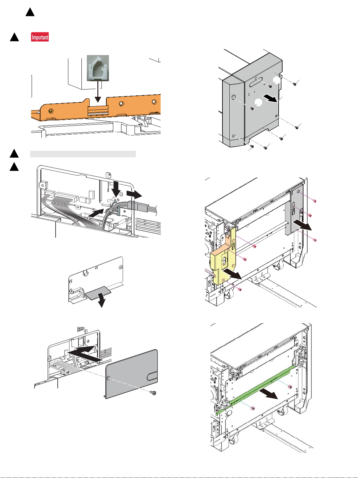
Be careful of the mounting direction.
Open the right side.
1 stage desk: No.12
2/3 stage desk: No.14
Ĭ
ĭ
Į
Ĭ
Ĭ
Ĭ
Ĭ
Ĭ
Ĭ
Ĭ
ĭ
: ‘16/Apr.
2
2) Attach the edge saddle.
2
3) Connect the heater harness to the machine harness.
2
The heater harness are held by the Edge saddle.
2
F. LCC heater kit installation
(1) cabinet removal
1) Remove screws and remove Rear cabinet.
2) Remove screws and remove Left front cabinet and Left rear cabinet.
4) Cut the part of the removed cover shown in the figure.
5) Attach the rear cabinet cover of the machine.
3) Remove screws and remove LCC unlock connecting plate.
MX-4070N Dehumidifying heater 5 – 22
Page 71
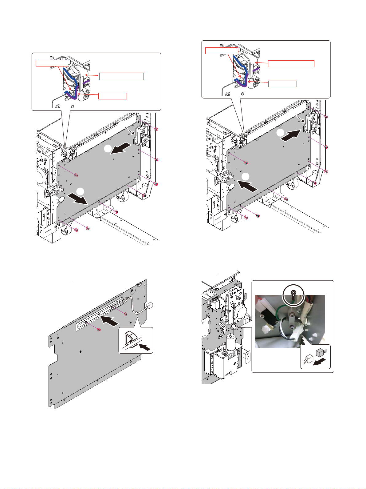
4) Remove the harnesses on Paper feed unit from the Edge saddle.
Ĭ
ĭ
A
*CTPGUUGU
'FIGUCFFNG
2CRGTHGGFWPKV
Ĭ
ĭ
A
*CTPGUUGU
'FIGUCFFNG
2CRGTHGGFWPKV
Remove screws, slightly pull out the rear side of the LCC connecting plate left toward front and slightly slide toward rear side.
Remove the harness avoiding the section A.
2) Attach LCC connecting plate left and put the harnesses through
the Edge saddle on Paper feed unit.
(2) Heater attachment
1) Attach Heater and M clamp. Put the harness through the M
clamp.
(3) Heater harness unit attachment
1) Attach AC cord fixer and Heater harness as shown below and fix
the round terminal with a screw.
Connect the Heater harness connector and Heater connector.
MX-4070N Dehumidifying heater 5 – 23
Page 72
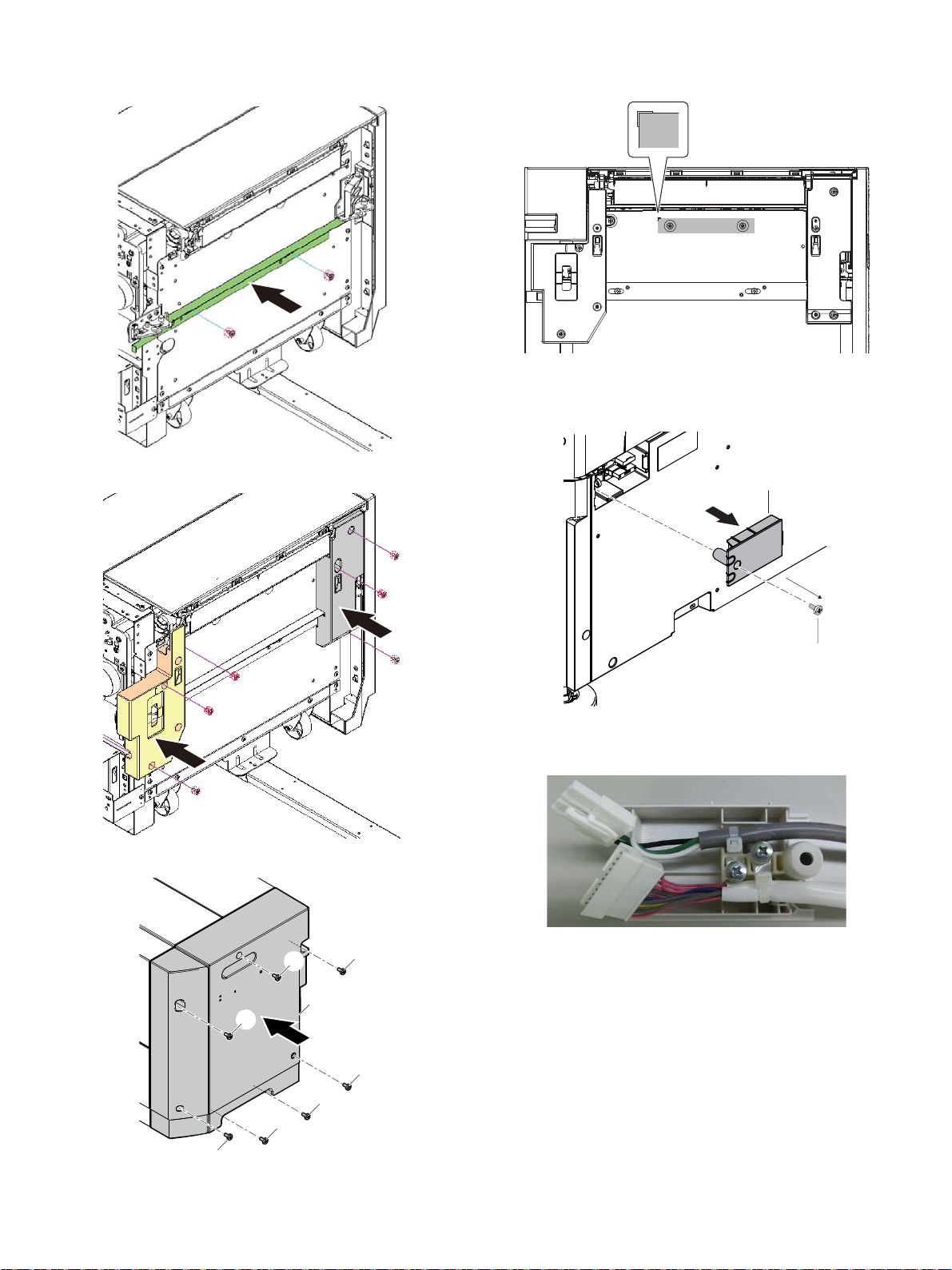
(4) Cabinet attachment
ĭ
ĭ
ĭ
ĭ
ĭ
ĭ
ĭ
Ĭ
Ĭ
ĭ
.%%JCTPGUUKUEQXGTGFYKVJCEQPPGEVQTEQXGT
1) Attach the LCC unlock connecting plate.
2) Attach Left front cabinet and Left rear cabinet.
4) Paste a protection sheet according to the cutout position on the
plate.
(5) Connector connection
1) Remove the connector cover.
Do not use the connector cover removed.
3) Attach Rear cabinet.
2) Connect the connector.
If the dehumidifier heater kit is not installed, there is no need to
connect the dehumidifier heater connector to the connector.
MX-4070N Dehumidifying heater 5 – 24
Page 73
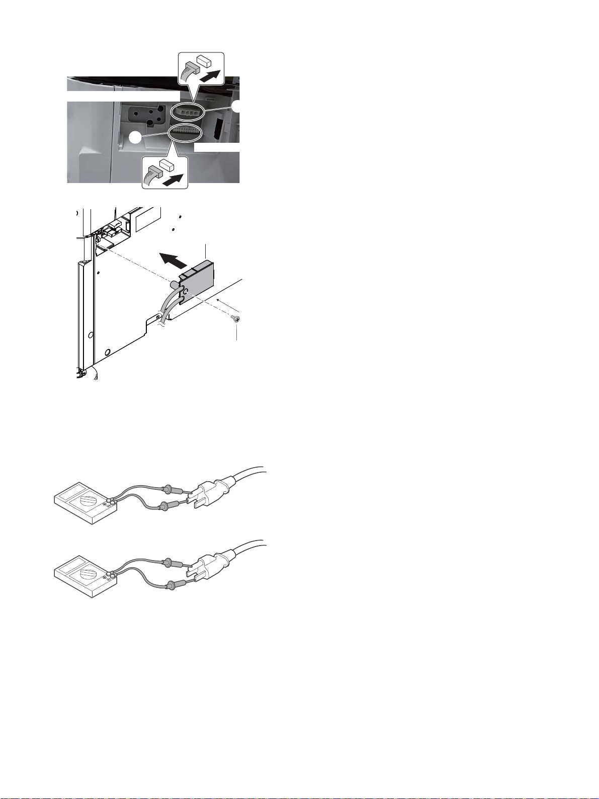
G. Operation check after installation
Thedehumidifierheaterconnector
MX-LC17connector
Ĭ
ĭ
Ĭ
ĭ
1) Turn on the dehumidifier heater switch.
2) Measure the resistance value between the earth terminal and the
AC terminal (L side), and between the earth terminal and AC terminal (N side) with the circuit tester, and confirm they are not
short-circuited.
3) When not using the dehumidifier heater after checking, turn off the
dehumidifier heater switch.
MX-4070N Dehumidifying heater 5 – 25
Page 74
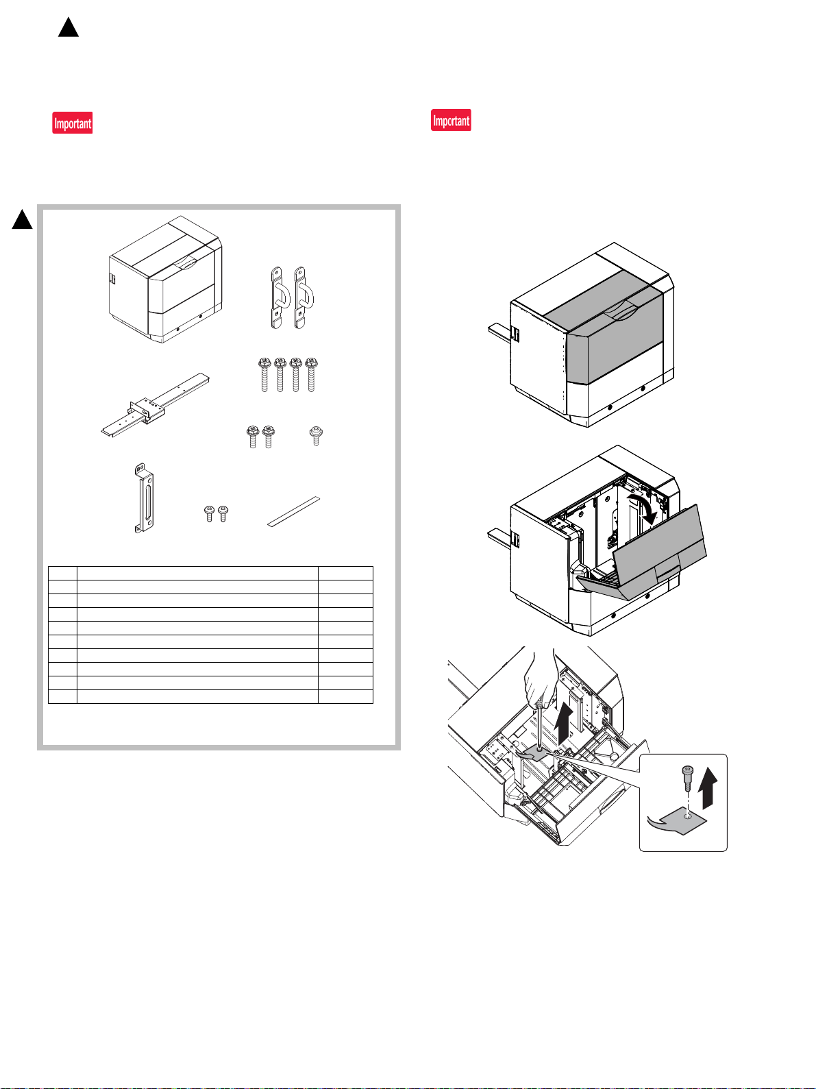
21
3
4
6
78
5
9
: ‘16/Apr.
2
MX-4070N
[6] MX-LC17 (LARGE CAPACITY TRAY)
Service Manual
1. Unpacking
If the connector is removed first, it may be damaged during the installation procedures. Therefore, keep it packed while un-boxing and
unpack it only when connecting the connector to the machine.
A. Packed items check
2
2. Installation
Before installation, be sure to turn both the operation and main power
switches off and disconnect the power plug from the power outlet.
Make double sure that the data lamp on the operation panel does not
light up or blink when performing installation.
A. Release the lock
1) Remove the paper feed desk fixing screw.
No. Name Quantity
1 Large capacity tray 1
2 Mounting plate upper 2
3 Connecting unit 1
4 Fixing screw A (Hex washer S-tight M4x18) 4
5 Fixing screw B (Hex washer S-tight M4x12) 2
6 Fixing screw C (M4x8 cup) 1
7* LCC fixing plate 1
8* Screw (M3x6 S-tight bind) 2
9 LCC Guide sheet 1
* Not used for November 2015 production upward of paper drawer
(MX-DE25/DE26/DE27/DE28).
NOTE: Before turning on the power, check to insure that the fixing
screw of the tray is removed. If the power is turned on without
removing the fixing screw, a trouble may be resulted.
MX-4070N MX-LC17 (LARGE CAPACITY TRAY) 6 – 1
Page 75
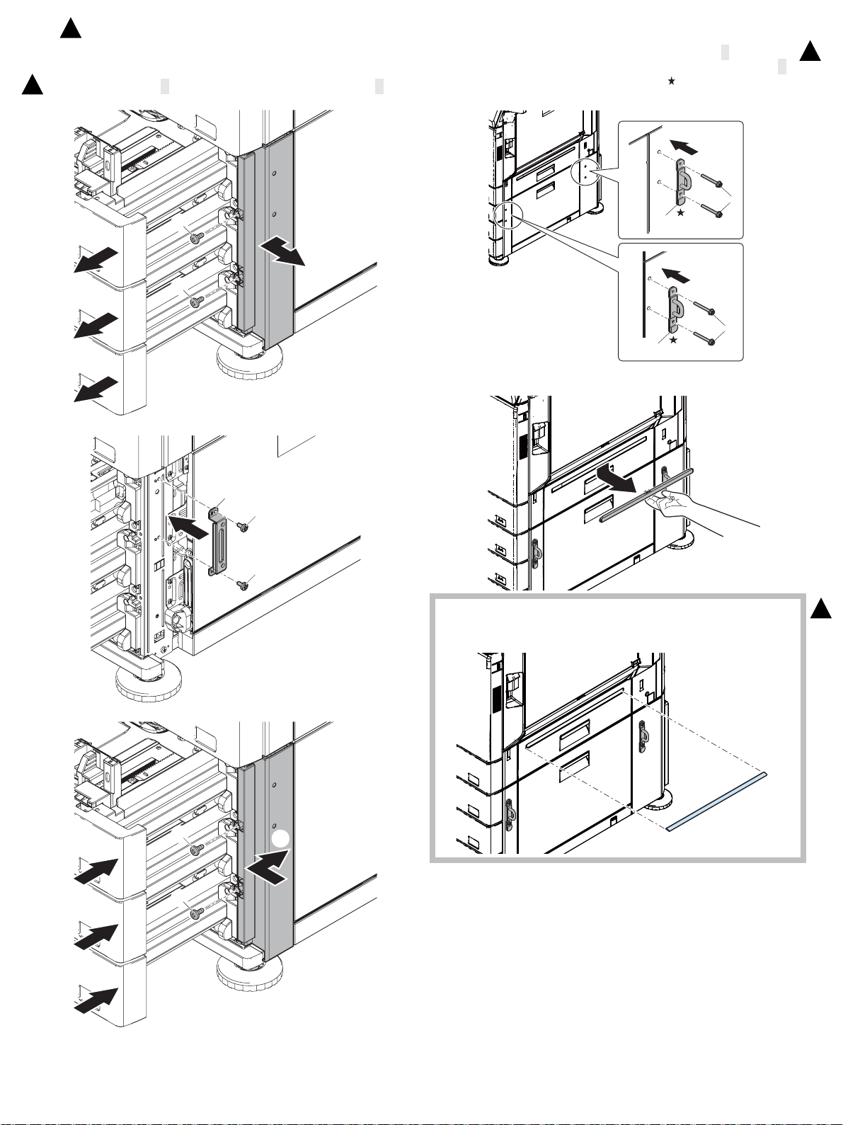
Ĭ
Ĭ
Ĭ
ĭ
ĭ
Į
Ĭ
ĭ
ĭ
Į
Į
Į
ĭ
ĭ
Ĭ
Ĭ
ĭ
Ĭ
ĭ
: ‘16/Apr.
2
B. Main unit and large capacity tray unit connection
1) Remove the Desk left front cabinet. Attach LCC fixing plate
2
(Packed item No. 7) with M3x6S tight bind (Packed item No. 8).
2) Attach the mounting plate upper (Packed item No.2) to the right
side of main unit with the fixing screw A (Packed item No.4).
When installing, put the rubber section ( ) of the mounting plate
upper on the lower side.
3) Remove the right door cover from the machine.
2
4) Attach the LCC guide sheet (Packed item No.9) onto the paper
entering guide.
Clean surface of the LCC guide sheet with alcohol.
2
MX-4070N MX-LC17 (LARGE CAPACITY TRAY) 6 – 2
Page 76
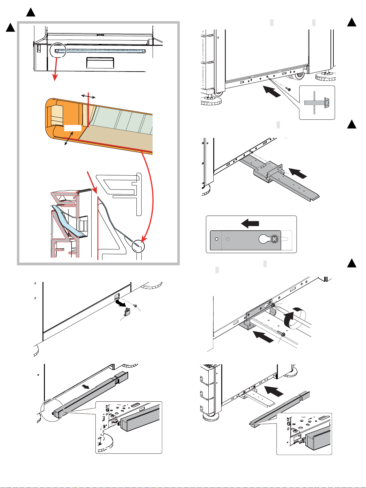
Attachment position of LCC guide sheet.
Be sure no protruding the tip of the sheet
on the paper transportation guide.
Sectional view.
0mm
0.5mm
0mm
0.5mm
Ĭ
ĭ
Ĭ
ĭ
ĭ
Ĭ
: ‘16/Apr.
2
6) Temporarily fix the fixing screw B (Packed item No.5) midway.
2
2
5) Remove the fixing screws (1 pc) of the machine and remove the
screw cap. And remove the right under cover.
7) Insert the temporarily fixed screw B into the key hole in the connection unit and temporarily fix the connection unit.
8) Fix the other fixing screw B and tighten the temporarily fixed
screw B securely.
2
2
9) Attach the right under cover back to the main unit.
MX-4070N MX-LC17 (LARGE CAPACITY TRAY) 6 – 3
Page 77
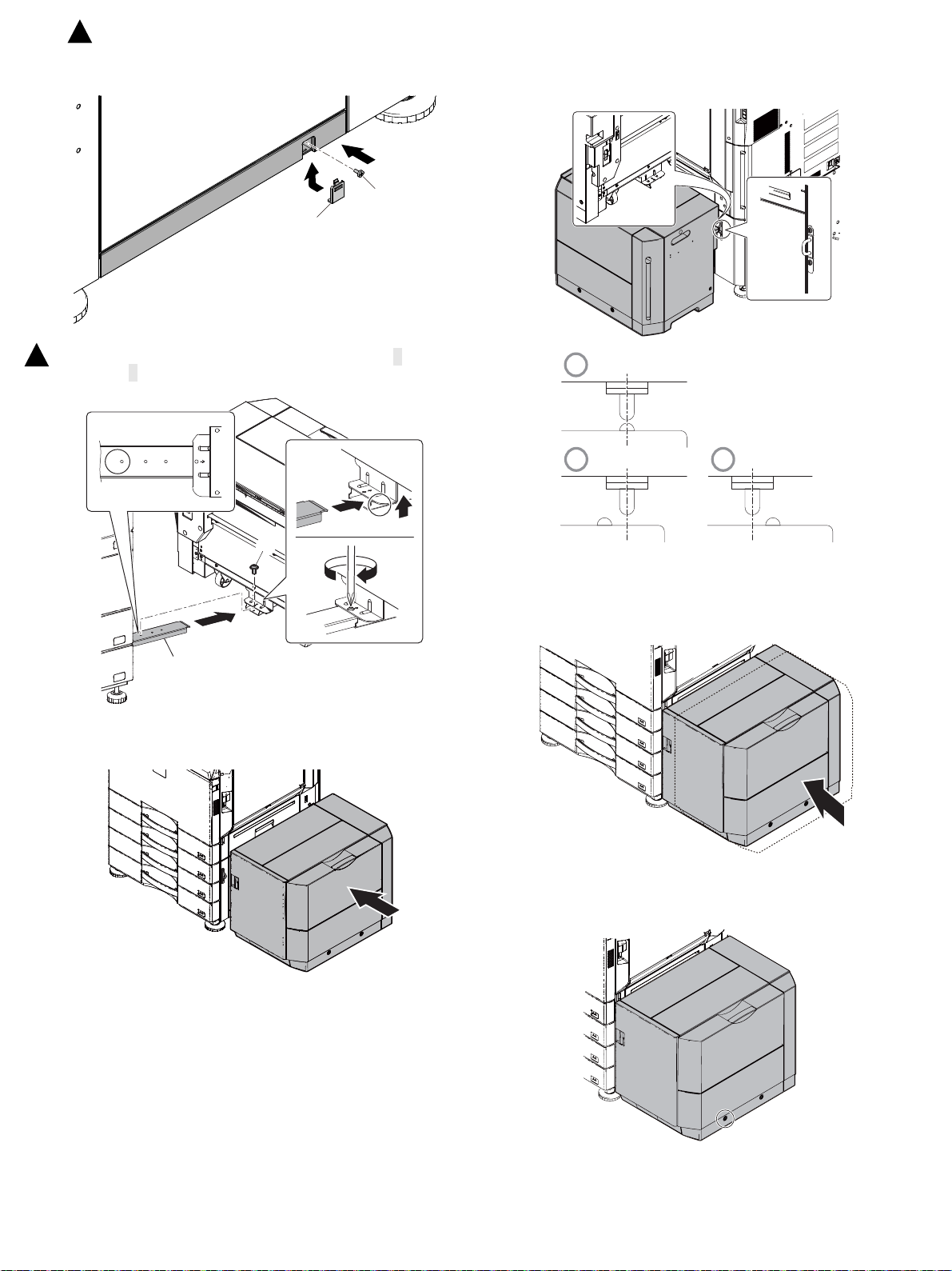
Ĭ
ĭ
Ĭ
Ĭ
ĭ
A
B
OK
NG NG
: ‘16/Apr.
2
10) Fix the fixing screw, and attach the screw cap back to the main
unit.
11) While lifting the section marked with ○ insert the connection unit
2
into the large capacity tray unit and fix the fixing screw C (Packed
item No.6) at the mark A on the connection unit.
2) Check to insure that the height adjustment check rib of the large
capacity tray unit and the axis line of the mounting plate upper
mounted to the main unit are in the same line.
C. Height adjustment
1) Put the large capacity tray unit closer to the main unit.
3) If the height adjustment is not required, insert the large capacity
tray unit further more.
If the height adjustment is required, perform the adjustment procedure from 4).
4) Loosen the adjustment screw on the F side.
NOTE: Use the adjustment screw on the front side for the adjust-
ment. Do not touch the screw on the rear side.
MX-4070N MX-LC17 (LARGE CAPACITY TRAY) 6 – 4
NOTE: If the screw is loosened or removed when servicing, be
sure to execute C Height adjustment after completion of
servicing.
Page 78
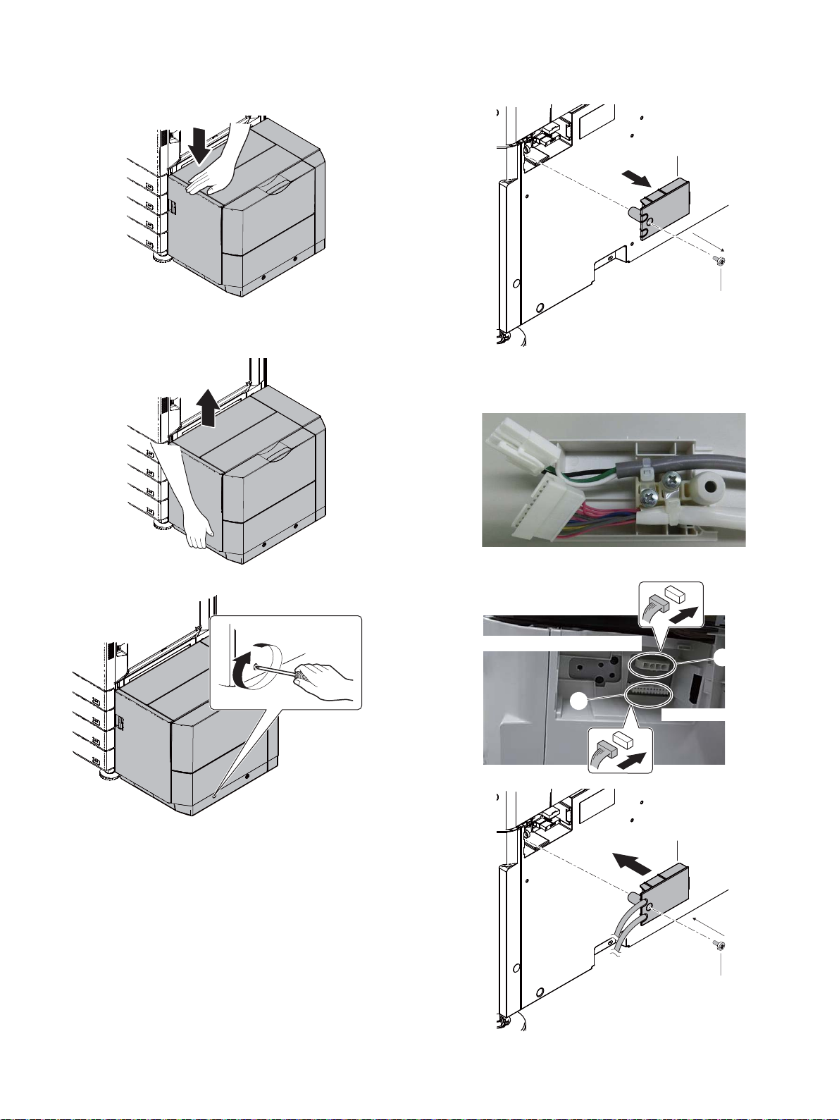
5) In the case of a shift to the right, press the front upper section and
Ĭ
ĭ
.%%JCTPGUUKUEQXGTGFYKVJCEQPPGEVQTEQXGT
Thedehumidifierheaterconnector
MX-LC17connector
Ĭ
ĭ
Ĭ
ĭ
fit the height adjustment check rib so that it is in the same line with
the axis line of the mounting plate upper. Insert the large capacity
tray unit into the main unit.
6) In the case of a shift to the left, lift the grid so that the height
adjustment check rib is in the same line with the axis line of the
mounting plate upper and insert the large capacity tray unit.
D. Connector connection
1) Remove the connector cover.
Do not use the connector cover removed.
2) Connect the connector.
If the dehumidifier heater kit is not installed, there is no need to
connect the dehumidifier heater connector to the connector.
7) Tighten the loosened screw.
MX-4070N MX-LC17 (LARGE CAPACITY TRAY) 6 – 5
Page 79
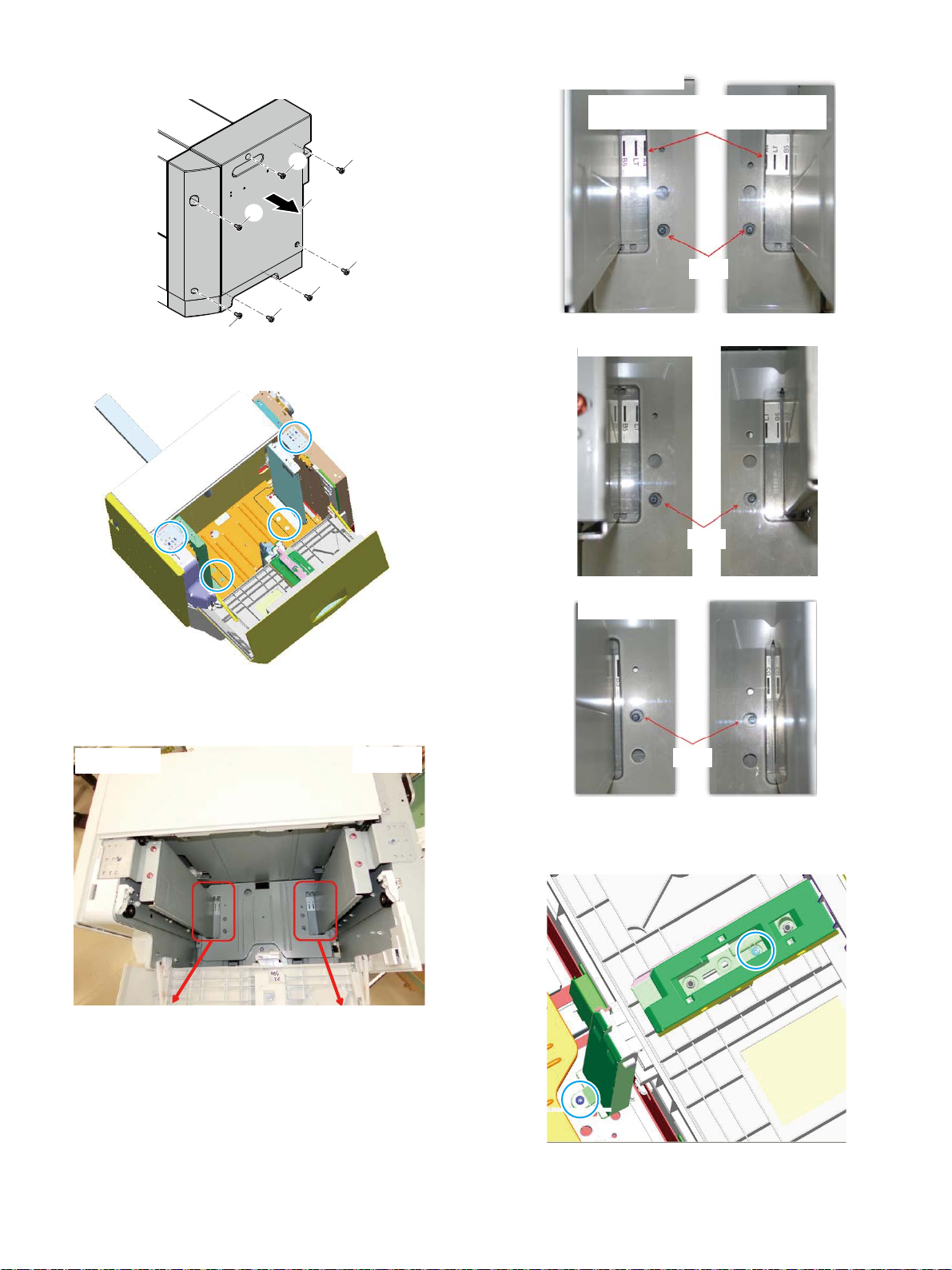
E. Paper size switch
Ĭ
Ĭ
Ĭ
Ĭ
Ĭ
Ĭ
Ĭ
ĭ
Fside
Rside
InthecaseofA4size
Screw
Whenitbesawedfromthetop,thelineoftheholealmost
overlapswithboldlineofeachsizeandseesit.
Screw
Screw
1) Remove Rear cabinet.
2) Remove fixing screw (4 pcs of blue screw) on upper and lower
side of Side plate F and Side plate R.
3) Insert the lower side according to the engraved mark on the lower
side of Side plate F and Side plate R. Tighten upper and lower
side using the fixing screws being removed.
InthecaseofLTsize
InthecaseofB5size
4) Switching Rear edge plate
Remove the blue screws fixing the upper and lower Rear edge
plate respectively.
MX-4070N MX-LC17 (LARGE CAPACITY TRAY) 6 – 6
Page 80
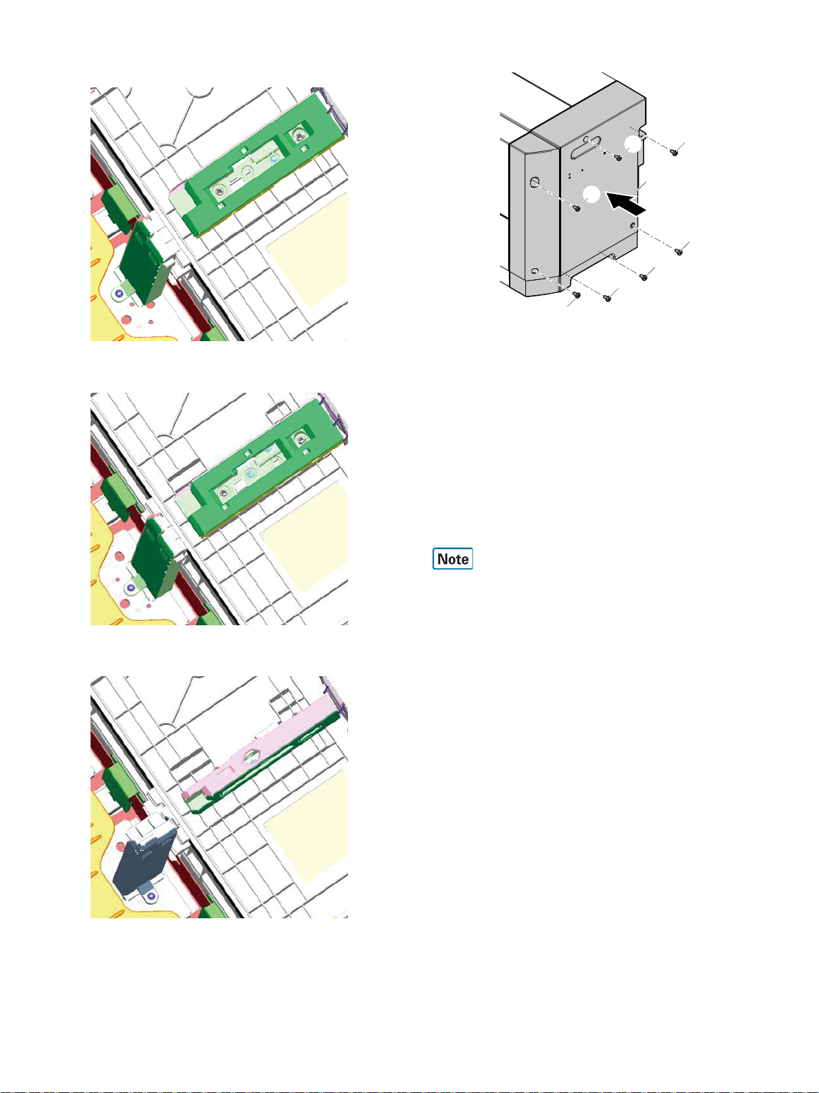
5) Insert Size guide according to the engraved mark. Tighten upper
ĭ
ĭ
ĭ
ĭ
ĭ
ĭ
ĭ
Ĭ
and lower side using the fixing screws being removed (A4).
(LT)
6) Attach Rear cabinet.
F. Turn ON the power of the main unit
1) Connect the power plug of the machine to the power outlet, and
turn ON the main power switch and the operation panel power
switch.
G. Size setting
Execute SIM 26-2 "Size setting" with the key operations of the main
unit.
1) The size selection menu of the large capacity tray is displayed on
the operation message display.
2) Select a size button to be set on the message screen.
H. Image off-center adjustment
(1) Adjustment with the simulation
(B5)
The image lead edge position and the off-center adjustment value of
the desk unit have been set to the average value when shipping from
the factory.
Therefore, this adjustment must be performed only when the judgment
is made to execute it through checking the print image.
* There must be a tray with A4 (LT) paper in it.
1) Enter the Sim. 50-10 mode.
2) Select a paper feed source “6“ (LCC).
3) Set A4 (11 X 8.5) paper on the LCC paper feed tray.
4) Check to confirm that the inside dimension of the printed half-tone
pattern is 2400.5mm.
If the above condition is not satisfied, follow and repeat the procedures of ADJ4A(Service manual) until a satisfactory result is
obtained.
5) Measure the void area size of the adjustment pattern in the front/
rear frame direction (F side void amount) and that in the transport
direction (Lead edge void amount).
Check to confirm that all the following conditions are satisfied.
MX-4070N MX-LC17 (LARGE CAPACITY TRAY) 6 – 7
Page 81
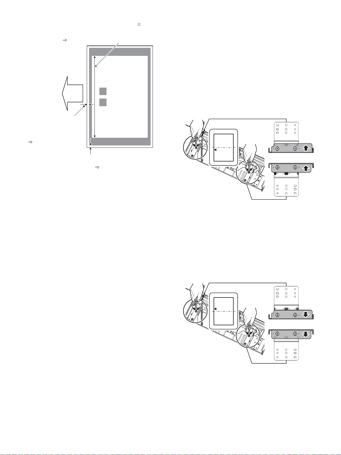
Calculation and input procedures of adjustment values
s,EADEDGEVOIDAMOUNT
MMTERGET
-EASUREATTHECENTEROF
PAPER
!DJUSTMENTVALUE
,35",#
Print
lead edge
Main scanning magnification ratio (240 0.5mm)
Measure the dimension near the inner frame line
and the paper lead edge in parallel with the line.
Adjustment value A : BK-MAG
s&SIDEVOIDAMOUNTMMTERGET
-EASUREATAPOSITIONNEARTHE
PAPERLEADEDGE
!DJUSTMENTVALUE
'-!).,#
A
R side
F side
B
R side
F side
(Example) Lead edge void amount
(1) Measure by visual inspection.
Measurement result: 3.5mm
(2) Calculate the shift amount.
The target value is the specification value (center value) of
3mm.
* For the F side void amount, the target is 2mm.
[3 – 3.5 = -0.5 (mm)]
(3) Calculate the adjustment value.
Subtract 5 from the shift amount of -0.5mm.
* For the shift amount of 0.1mm, the adjustment value is
varied by 1.
When the current value is 50:
[50 – 5 = 45]
(4) Enter the adjustment value for SUB-LC.
Enter the [45].
6) Enter MAIN-LC (F side void) and SUB-LC (Lead edge void), and
press OK button.
Enter the calculated adjustment values for the shift amount to
MAIN-LC/SUB-LC, and press OK button. (The cursor can be used
instead of the button.)
7) After entering the adjustment values, print again and check to
confirm that the avoid amounts are adjusted to the target range.
Perform procedures 4) to 7) for each paper feed tray.
(2) Mechanical adjustment
Since the off-center adjustment is performed when shipping, there is
basically no need to perform this adjustment. If the center is shifted,
however, the simulation is normally used. If the shift is not removed,
perform the following adjustment procedures.
a. When the shift is in the front side
To adjust the print line in the direction A from the paper center as
shown in the figure:
1) Loosen two fixing screws (red screws) of the front/rear size guide
adjustment plate, and move the size guide adjustment plate in the
direction A (R side) by the shift amount, and tighten the red fixing
screws (2 for each).
Then make a copy to check to insure that there is no more shift.
Repeat the procedures until there is no shift.
b. When the shift is in the rear side
To adjust the print line in the direction B from the paper center as
shown in the figure:
1) Loosen two fixing screws (red screws) of the front/rear size guide
adjustment plate, and move the size guide adjustment plate in the
direction B (F side) by the shift amount, and tighten the red fixing
screws (2 for each).
Then make a copy to check to insure that there is no more shift.
Repeat the procedures until there is no shift.
MX-4070N MX-LC17 (LARGE CAPACITY TRAY) 6 – 8
Page 82
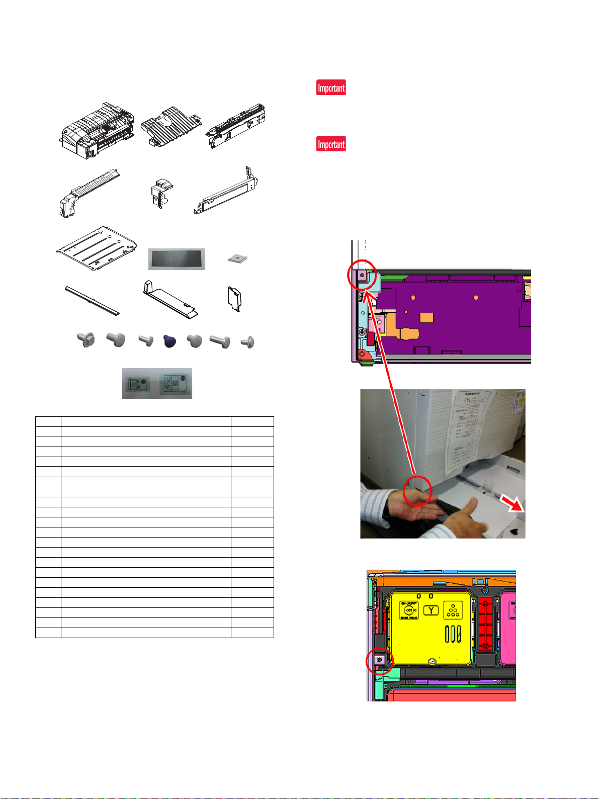
12 3
45 6
45 6
789
10
11
20
13
14
15
16
17
18
19
12
21
MX-4070N
[7] MX-FN27 (FINISHER)
Service Manual
1. Unpacking
A. Packed items check
2. Installation
Check to confirm that the firmware version is later than below.
If the version is older, upgrade the firmware.
Firmware version:
Before installation, be sure to turn both the operation and main power
switches off and disconnect the power plug from the power outlet.
Make double sure that the data lamp on the operation panel does not
light up or blink when performing installation.
A. Attach the Inner Finisher
1) Pull out the paper tray1, and remove the screw (x1) fixing the left
cabinet.
No. Name Quantity
1 Finisher 1
2 Delivery tray 1
3 Dummy punch unit 1
4 Punch unit cover 1
5 Connector cover 1
6 Positioning plate 1
7 Base plate 1
8 Mylar 1
9 Screw bracket 1
10 Front cabinet 1
11 Left cabinet 1
12 Connector cover 1
13 Screw (M4 x 6 RS tight) 2
14 Screw (M4 x 8 Black) 1
15 Screw (M3 x 6) 4
16 Screw (M3 step screw) 1
17 Screw (M4 x 6) 2
18 Screw (M4 x 12 P tight) 2
19 Screw (M3 x 6 RS tight) 1
20 Staple position label (For the scanner) 1
21 Staple position label (For the SPF) 1
2) Open the front cabinet, and remove the screw (x1) fixing the left
cabinet.
MX-4070N MX-FN27 (FINISHER) 7 – 1
Page 83
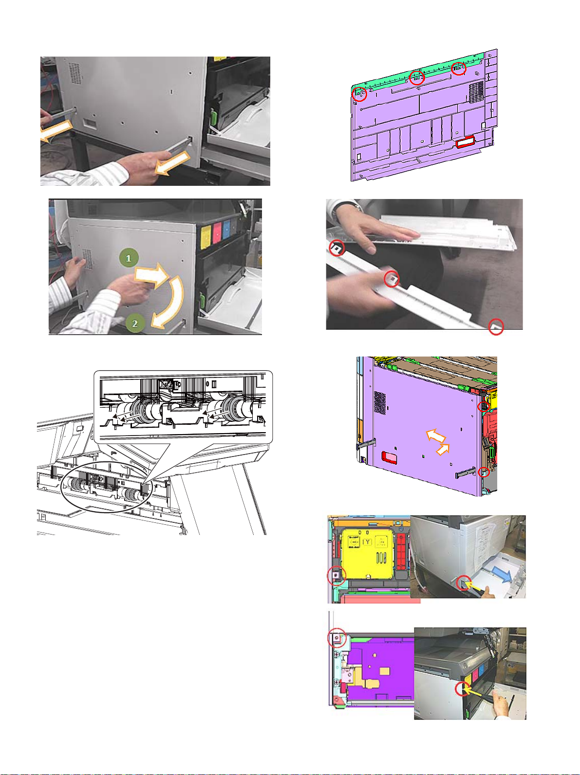
3) Pull out the grip at the left side of the main unit, and remove the
left cabinet while sliding it to the front side.
5) Take off the hooks (x3) and remove the left cabinet.
4) Remove four kick-out sponge rollers.
Be sure not to leave the pieces of the sponge.
6) Mount the left cabinet, and fix it with the screws (x2).
MX-4070N MX-FN27 (FINISHER) 7 – 2
Page 84
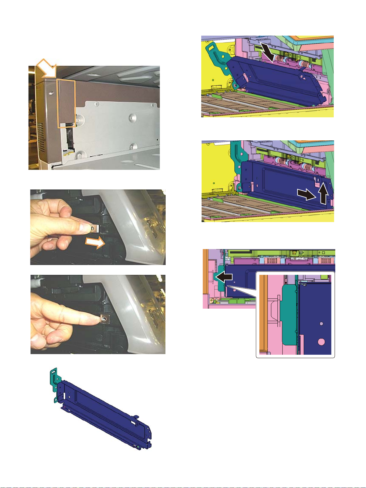
7) Put the grip back to the original position.
8) Close the front cabinet of the main unit.
9) Close the paper tray1.
10) Attach the Mylar to the main unit. (with reference to the edge of
the upper left).
11) Mount the screw bracket to the main unit while sliding it from the
left side.
13) Set the lower part of the positioning plate to the lower part of the
delivery unit.
14) Raise the positioning plate, and then slightly lift up the positioning
plate F side while sliding it to F side.
12) Attach the positioning plate to the main unit.(Package item No.6)
15) Insert the pawl of the positioning plate R side into the socket on
the main unit side.
MX-4070N MX-FN27 (FINISHER) 7 – 3
Page 85
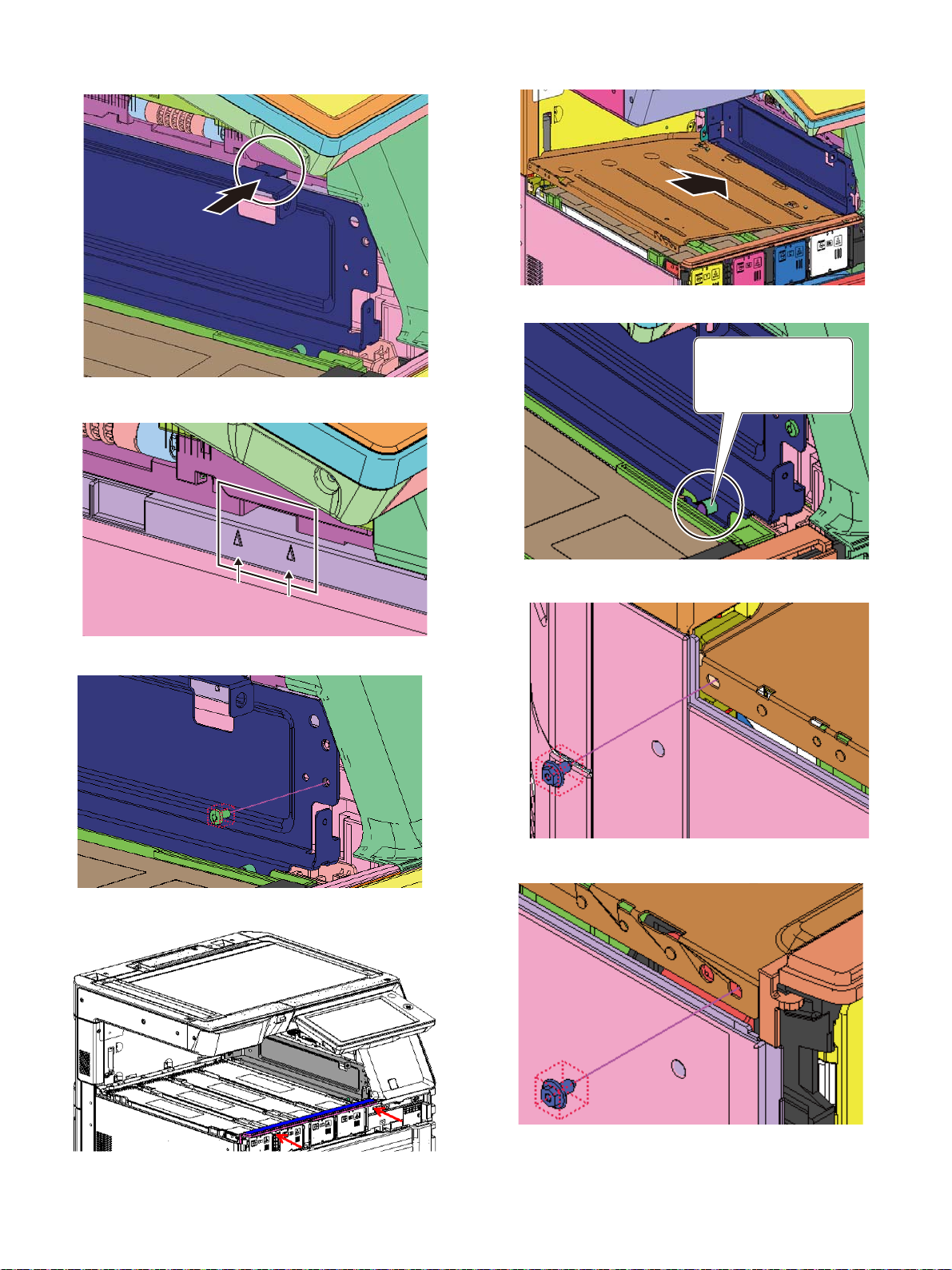
16) Insert the pawl of the plate F side into the socket on the main unit
#NKIPVJGJQNGQHVJGRNCVG
YKVJVJGDQUUQHVJG
RNCVGOQWPVGFHKTUV
side.
17) Insert the pawl into the section between ▲ marks of the main unit
side.
20) Attach the base plate to the main unit (Package item No.7).
18) Fit the plate to the dowel, and fix it with the screw (Package item
No.14).
19) Attach the front cabinet (Package item No.10), and fix it with the
screws (Package item No.18 x2).
21) Fix the plate with the screws (Package item No.13 x2).
Rear side
Front side
MX-4070N MX-FN27 (FINISHER) 7 – 4
Page 86
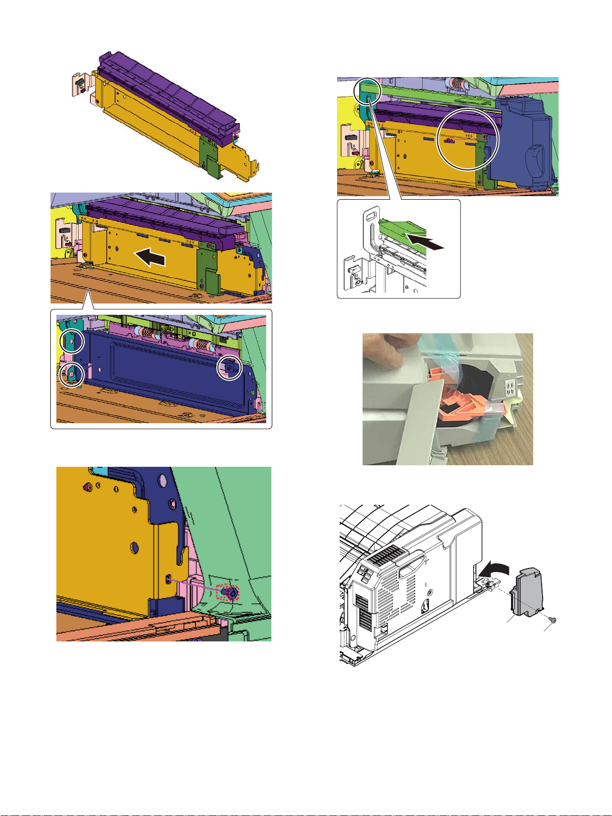
22) Attach the dummy punch unit (Package item No.3).
Ĭ
ĭ
24) Attach the punch unit cover (Package item No.4), and fix it with
the screw (Package item No.15 x1).
25) Take the orange parts(x2) out of the inner finisher.
23) Fix the dummy punch unit with the screws (Package item No. 15
x1).
26) Attach the connector cover (Packed items No.12) to the inner finisher with the screws (Packed items No.15).
MX-4070N MX-FN27 (FINISHER) 7 – 5
Page 87
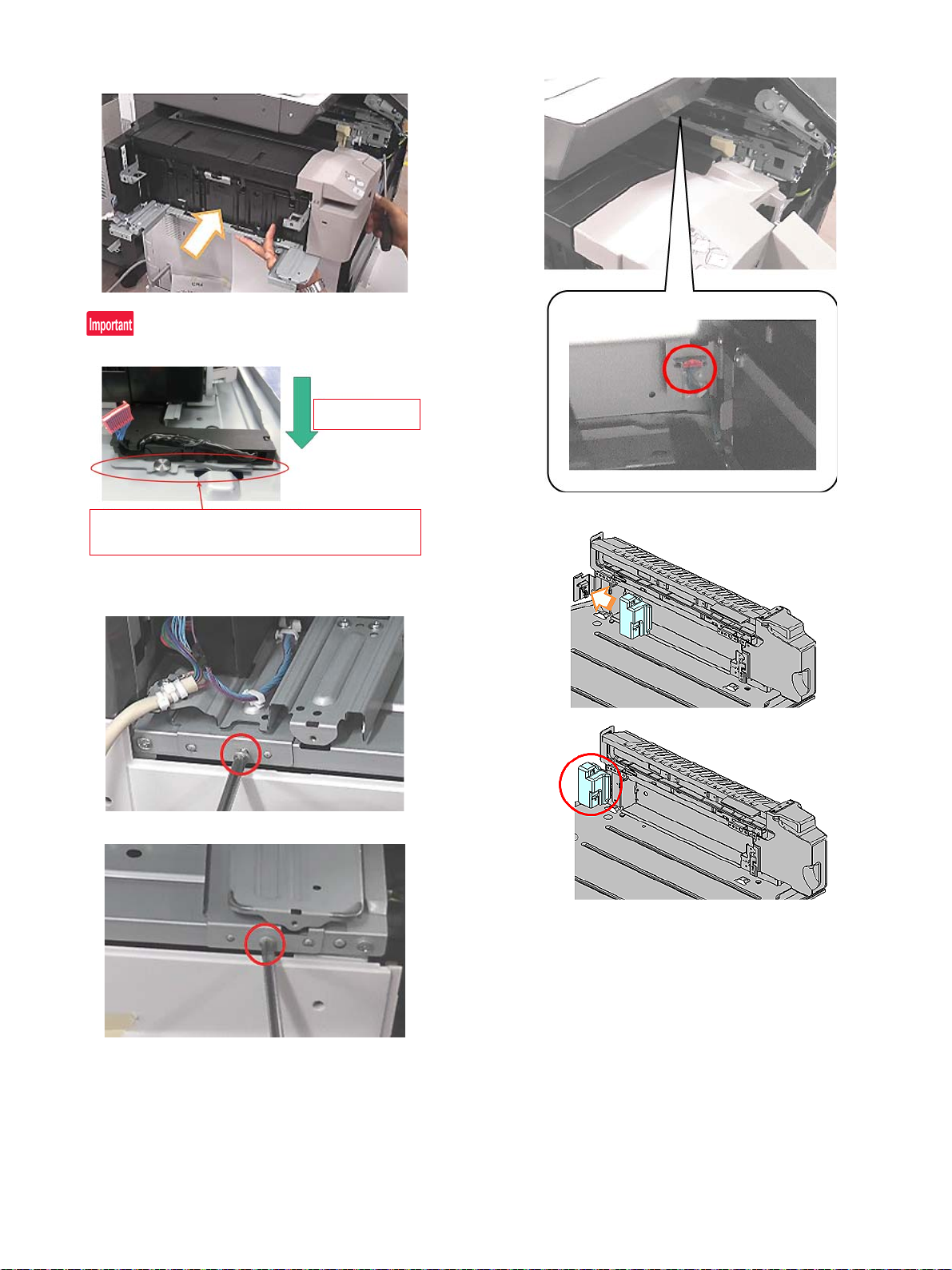
27) Mount the inner finisher while sliding it from the left side of the
Finisher attaching
direction
The harnesses could be pinched at the red frame part
shown in the figure during attaching the finisher and hook
the harness with the rein parts.
main unit.
29) Connect the connector of the inner finisher.
30) Attach the connector cover (Package item No.5).
28) Fix the inner finisher with the screws (Package item No17 x2).
Rear side
Front side
MX-4070N MX-FN27 (FINISHER) 7 – 6
Page 88
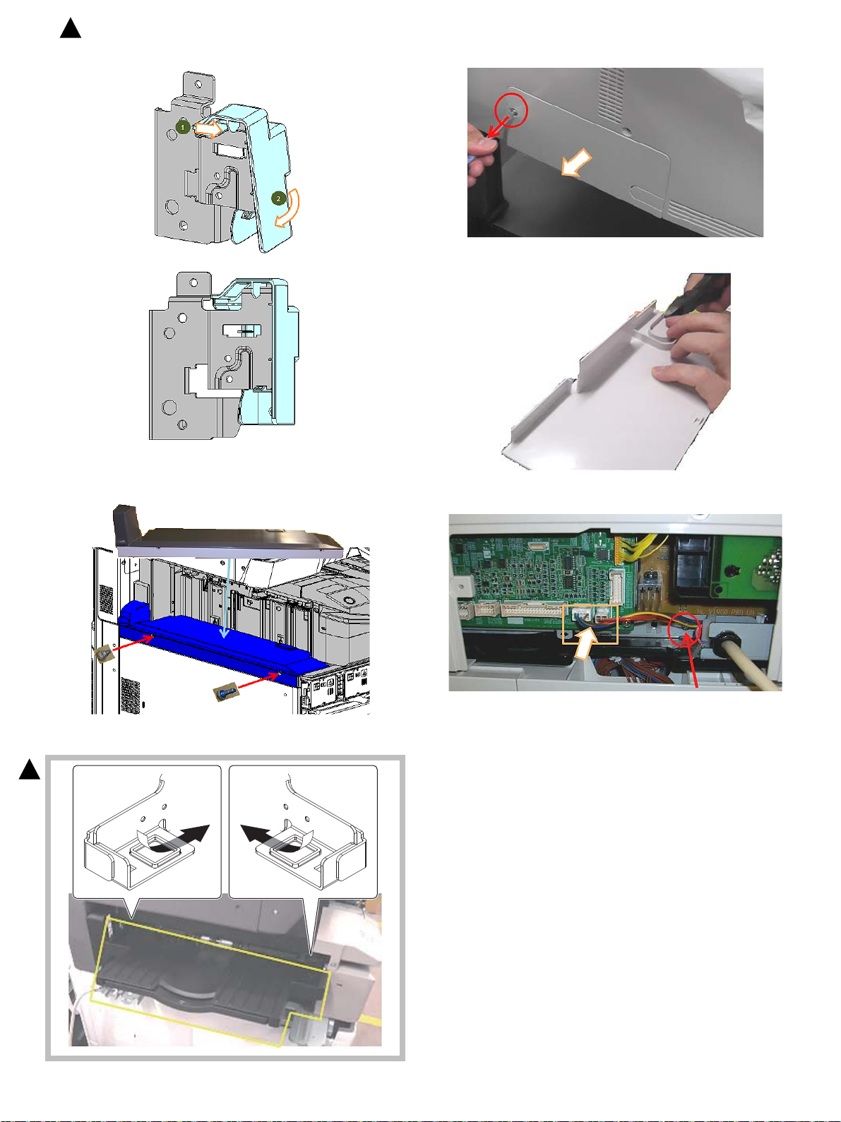
: ‘16/Sep.
3
Rear view
33) Remove the connector cover of the rear side of the main unit.
34) Cut the section where the harness gets through with the nipper.
31) Attach the left cabinet (Package item No.11) and fix it with the
screws (Front side: Package item No.15), (Rear side: Package
item No.16).
32) Attach the delivery tray (Package item No.2). Be careful not to let
a tray sensor creep in under the tray.
3
35) Secure the harness of the interface unit with the screw, and connect the connector (Package item No.19 x2).
36)
se the connector cover.
Clo
MX-4070N MX-FN27 (FINISHER) 7 – 7
Page 89
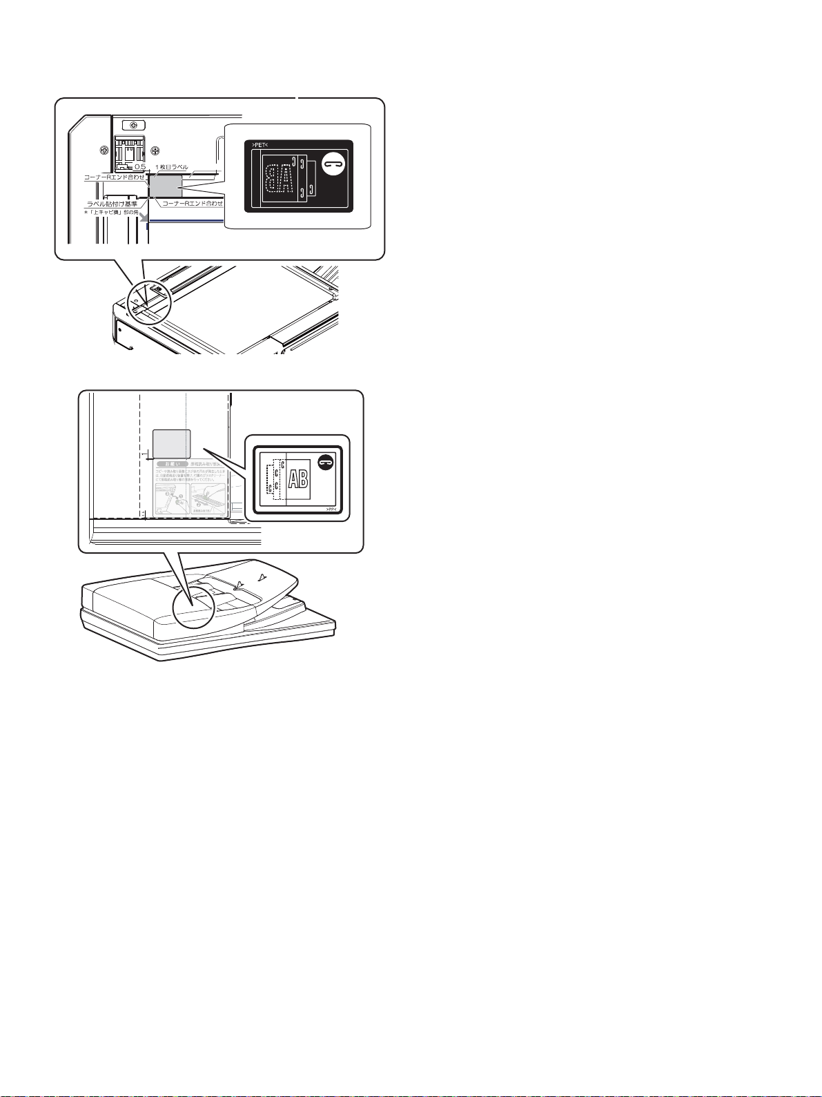
B. Staple position label attachment
1) Attach the staple position label (for the scanner).
2) Attach the staple position label.
C. Turn ON the power of the main unit
1) Connect the power plug of the machine to the power outlet, and
turn ON the main power switch and the operation panel power
switch.
MX-4070N MX-FN27 (FINISHER) 7 – 8
Page 90
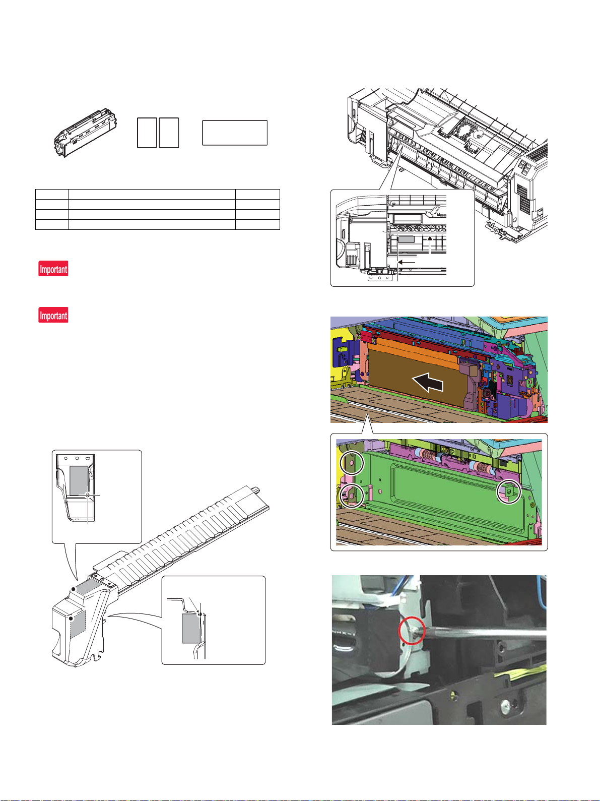
12 3
Reference
line for
affixing
Reference line for
affixing
Reference of intersecting
position
Reference of
end face
push against
Ĭ
MX-4070N
[8] MX-PN14B/C/D (PUNCH MODULE)
Service Manual
1. Unpacking
A. Packed items check
No. Name Quantity
1 Punch unit 1
2 Sound absorbing material 2
3 Cushion 1
2. Installation
Check firmware version.
Upgrade if the firmware version is old.
Turn off the power switch on operation panel and main power switch
prior to the installation.
Disconnect the power plug from the power outlet.
Make sure that data lamp on operation panel is not illuminating or
blinking before the installation.
A. Installation of Punch unit
1) Follow the procedure up to A-21) for MX-FN27.
2) Stick the Sound absorbing material (Packed items No.2) inside
the Punch unit cover.
3) Stick Cushion (Packed items No.3) to the Finisher.
4) Install Punch unit (MX-PN14).
5) Tighten a screw (package item No.15) to fix the Punch unit.
MX-4070N MX-PN14B/C/D (PUNCH MODULE) 8 – 1
Page 91
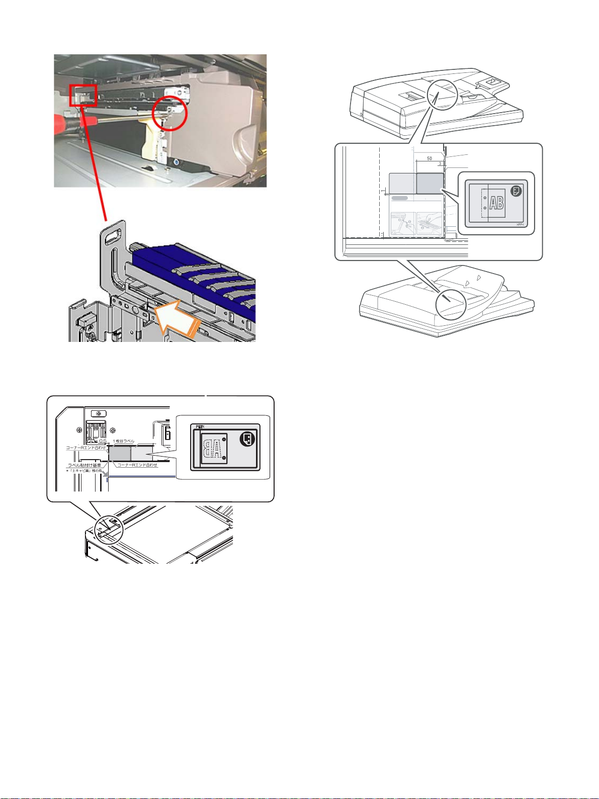
6) Tighten a screw (Package item No.15) to fix the Punch unit cover.
ᯛ┠ࣛ࣋ࣝ
For DSPF/RSPF
$30&
230&
R2.5 connection line
Edge line R 2.5
CAUTION
Cleaning of the document scan section
When streaks appear on copy or scan
images, open the automatic document
feed unit and clean the document scan
section with the glass cleaner (accessory).
Document scan section
7) Follow the procedure from A-25) to A-36) for MX-FN27.
B. Label attachment
1) Attach the punch position label (for the scanner).
2) Attach the punch position label (For DSPF/RSPF).
C. Turn ON the power of the main unit
1) Connect the power plug of the machine to the power outlet, and
turn ON the main power switch and the operation panel power
switch.
MX-4070N MX-PN14B/C/D (PUNCH MODULE) 8 – 2
Page 92
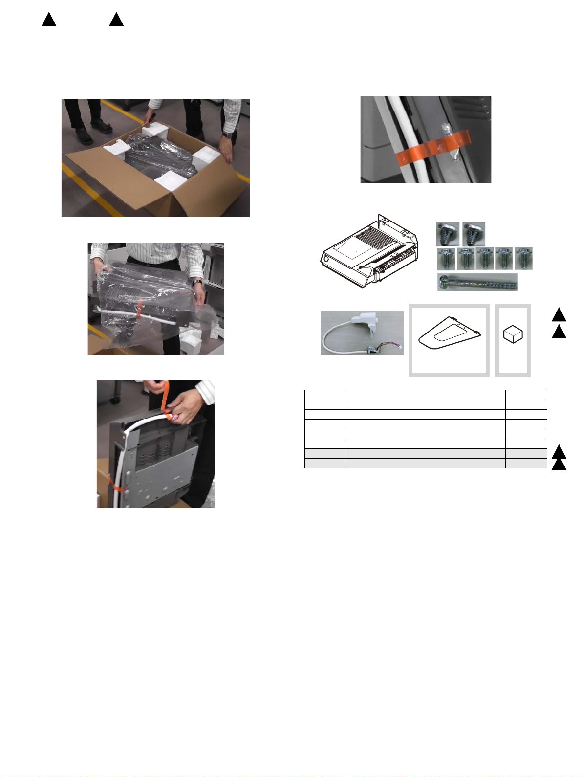
1
2
3
4
5
67
: ‘16/Feb.
1
MX-4070N
[9] MX-RB25 (PAPER PASS UNIT)
2
: ‘16/Apr.
Service Manual
1. Unpacking
1) Open the box.
2) Take the unit out of the box, and remove the plastic bag.
2. Packed items check
Bundled Parts are only the screws.
Bundled parts
1
2
3) Remove the tape.
No. Name QTY
1 Main unit of interface unit 1
2 Screw A (S Tight Bind 4-6) 2
3 Screw B (S Tight Cup 3-8) 5
4 Screw C (S Tight Bind 3-30) 1
5 Fin relay harness unit 1
6 Reverse gate tray 1
7 Base resting cushion 1
1
2
MX-4070N MX-RB25 (PAPER PASS UNIT) 9 – 1
Page 93
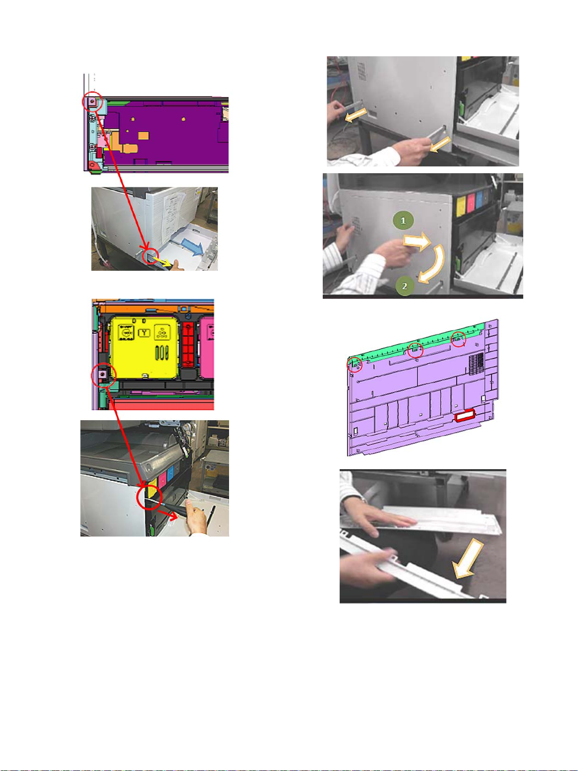
3. Installation
1) Pull out the paper tray1, and remove the screw (x1) fixing the left
cabinet.
2) Open the front cabinet, and remove the screw (x1) fixing the left
cabinet.
3) Pull out the grip at the left side of the main unit, and remove the
left cabinet while sliding it to the front side.
4) Remove the left cabinet upper from the left cabinet.
MX-4070N MX-RB25 (PAPER PASS UNIT) 9 – 2
Page 94
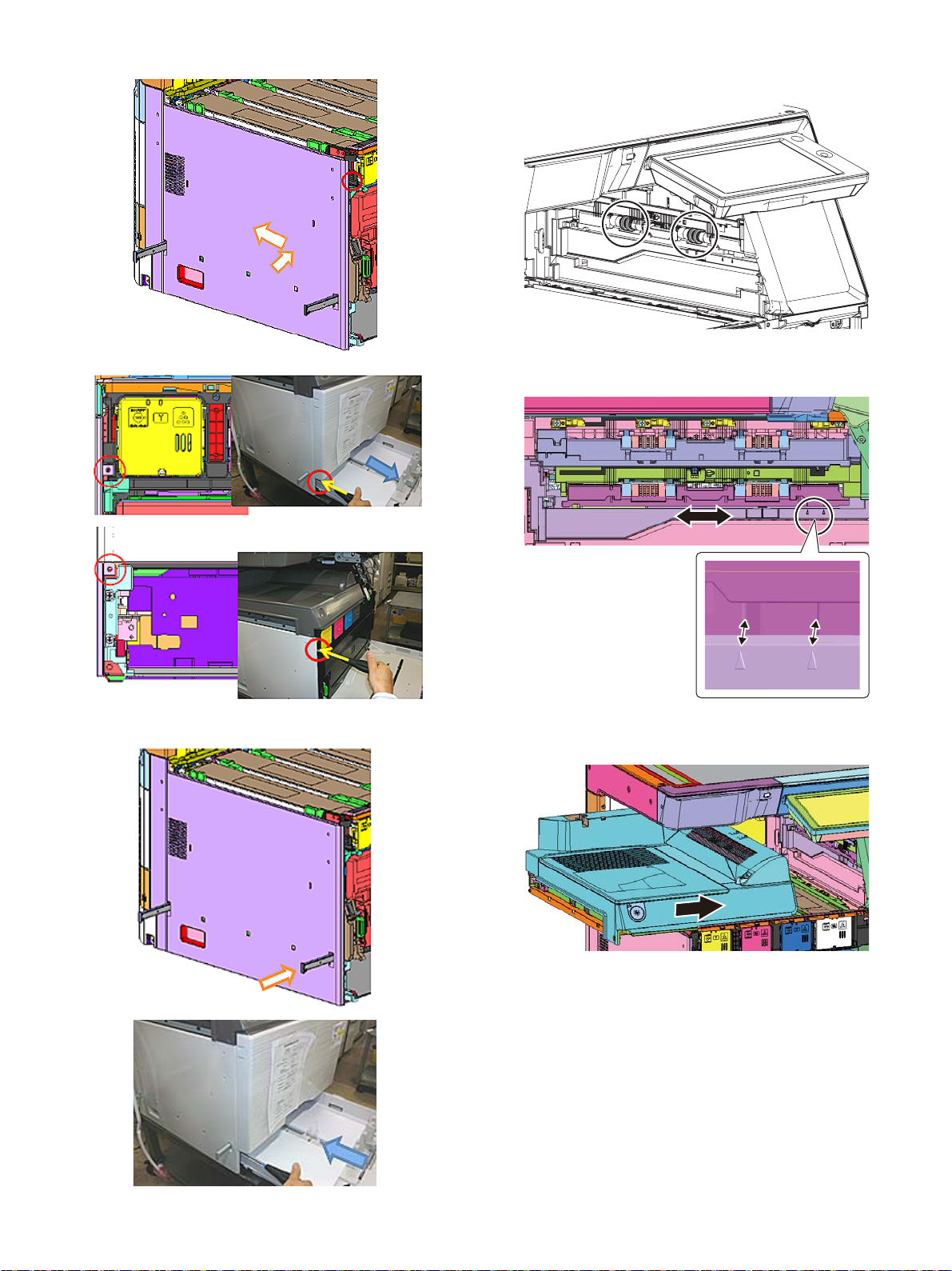
5) Mount the left cabinet, and fix it with the screws (x2).
7) Remove four lower kick-out sponge rollers.
Be sure not to leave the pieces of the sponge.
8) Adjust the front and rear position of the shifter by aligning the
edge of the recessed part with the triangular marking position.
6) Put the grip back to the original position
Close the paper tray1.
9) Mount the interface unit from the left side of main unit while sliding
it on the basis of the back side.
MX-4070N MX-RB25 (PAPER PASS UNIT) 9 – 3
Page 95
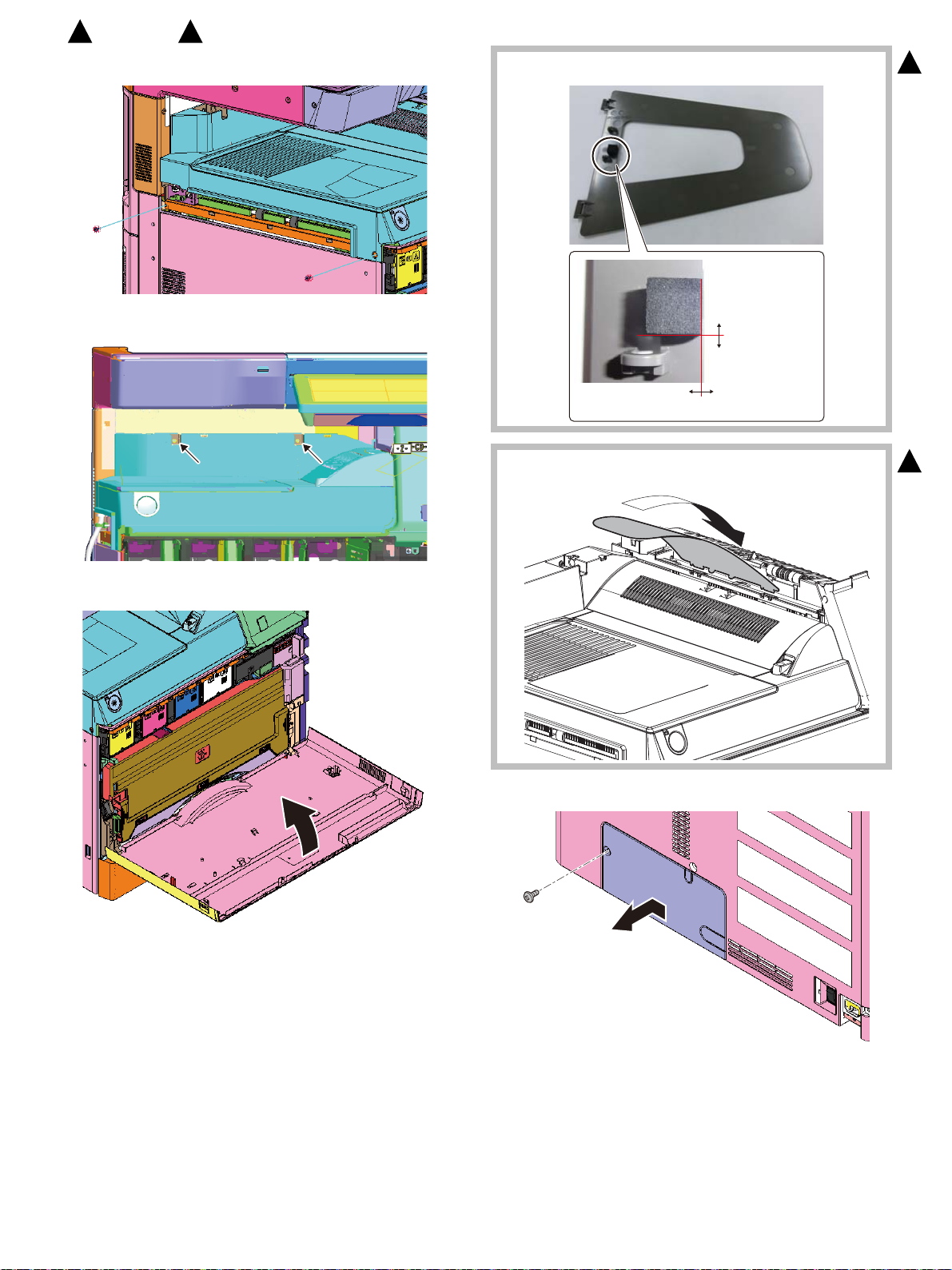
0mm2.0mm
2.0mm
0mm
Reference position
(Hole edge face)
Reference position (Hole edge face)
Ĭ
: ‘16/Feb.
1
10) Fix the interface unit with the screws (Packed items No.2 x2).
11) Fix the interface unit with the screws (Packed items No.3 x2).
2
: ‘16/Apr.
13) Affix base resting cushion on back side of reverse gate tray.
2
12) Close the front cabinet.
14) Attach the reverse gate tray (Packed item No.6)
15) Remove the connector cover of the rear side of the main unit.
1
MX-4070N MX-RB25 (PAPER PASS UNIT) 9 – 4
Page 96
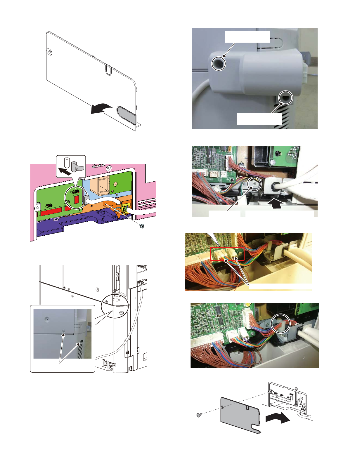
16) Cut the section where the harness gets through with the nipper.
Remove two screws
Fix it with the screwB
(Packed items No.3)
Fix it with the screwC
(Packed items No.4)
Screw B(No.3)
Insert the harness fixing plate to
the groove of main unit.
Connect the connector to the PWB.
19) Fix it with the screw.
17) Secure the harness of the interface unit with the screw (Packed
items No.3 x1), and connect the connector.
18) Remove two screws of the rear cabinet of the main unit and attach
the step screw at one place.
20) Insert the harness fixing plate to the groove of main u nit and fix
the harness fixing plate with the screw B (Packed items No.3).
21) Connect the connector to the PWB.
22) Pass the harness of the relay unit through the wire saddle.
23) Secure the connector cover with the screw (x1).
MX-4070N MX-RB25 (PAPER PASS UNIT) 9 – 5
Page 97
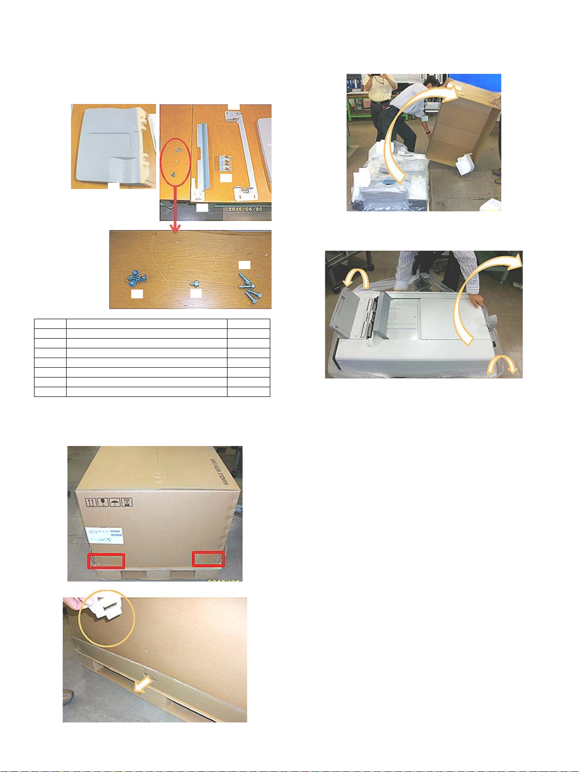
1
2
3
4
5
6
7
MX-4070N
[10] MX-FN28 (FINISHER)
Service Manual
1. Unpacking
A. Packed items check
No. Name Quantity
1 Shift tray 1
2 Guide plate 1
3 Screw (M3x6) 5
4 Screw (M4x8) 1
5 Screw (M4x12) 4
6 Earth plate 1
7 Bracket 1
B. Removal of the finisher
NOTE: It is reco mmendable to work by two or more persons.
1) Cut the tapes at four corners, and remove the fixture.
2) Take off the top case, and remove the cushioning materials.
3) Take out the finisher from the plastic bag.
While holding the upper parts of the finisher by two people, pull up
the finisher, and then make it stand upright.
C. Removal of the fixing tape and protection
material
1) Remove the fixing tape/protection materials.
2) Open the front upper cover, and remove the fixing tape/protection
materials.
MX-4070N MX-FN28 (FINISHER) 10 – 1
Page 98
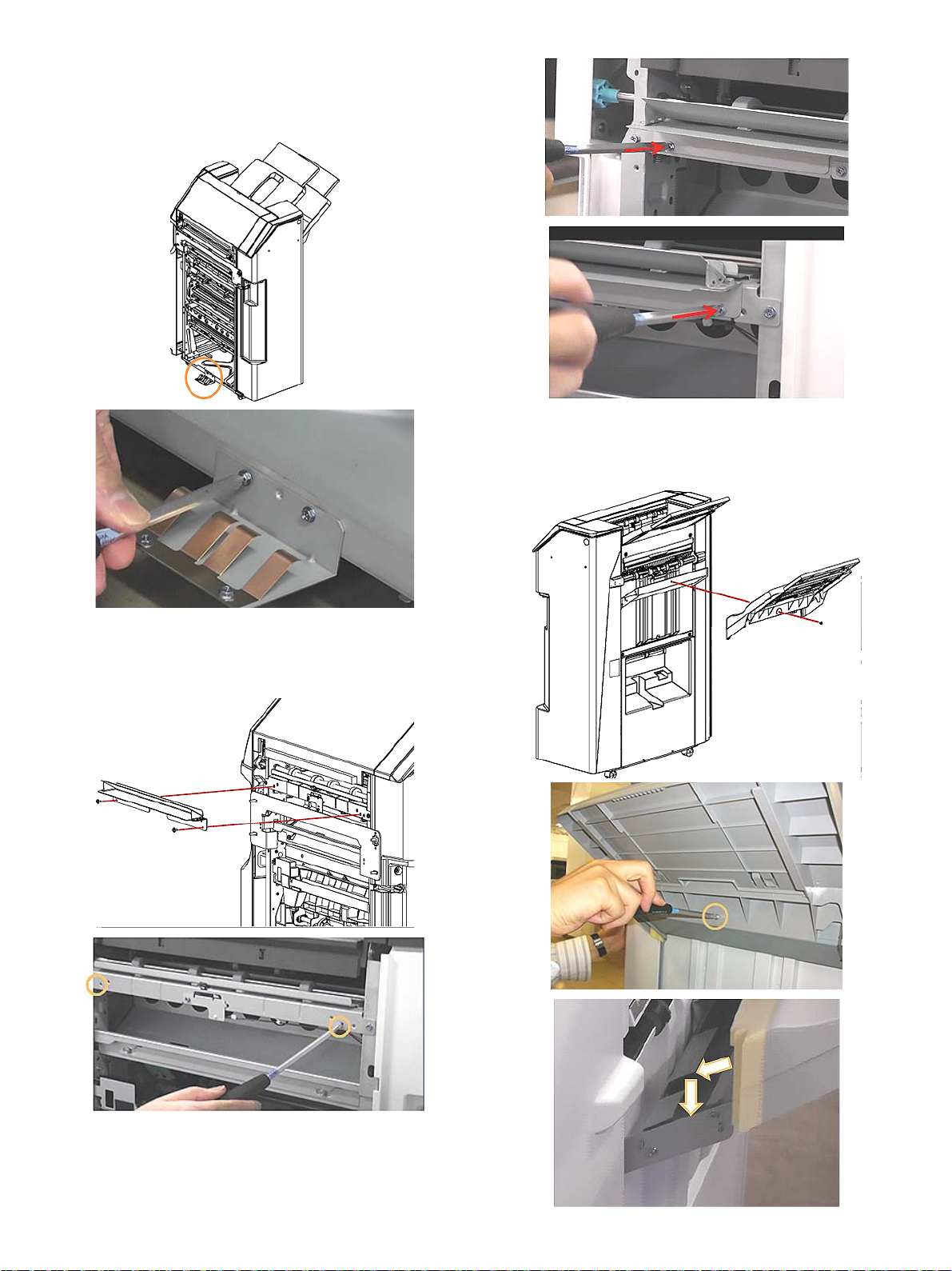
2. Installation
A. Installation of earth plate
1) Install the earth plate (Packed items (No.6)) with the screws
(Packed item (No.3 M3x6)).
C. Installation of the shift tray
1) Insert the shift tray (Packed item No.1) into the finisher of the main
unit, and install the shift tray with the screw (Packed item No.4
M4x8)).
B. Installation of the guide plate
1) Install the guide plate (Packed items (No.2)) with the screws
(Packed item (No.3 M3x6)). For the positions of the screws,
please see the picture below.
MX-4070N MX-FN28 (FINISHER) 10 – 2
Page 99
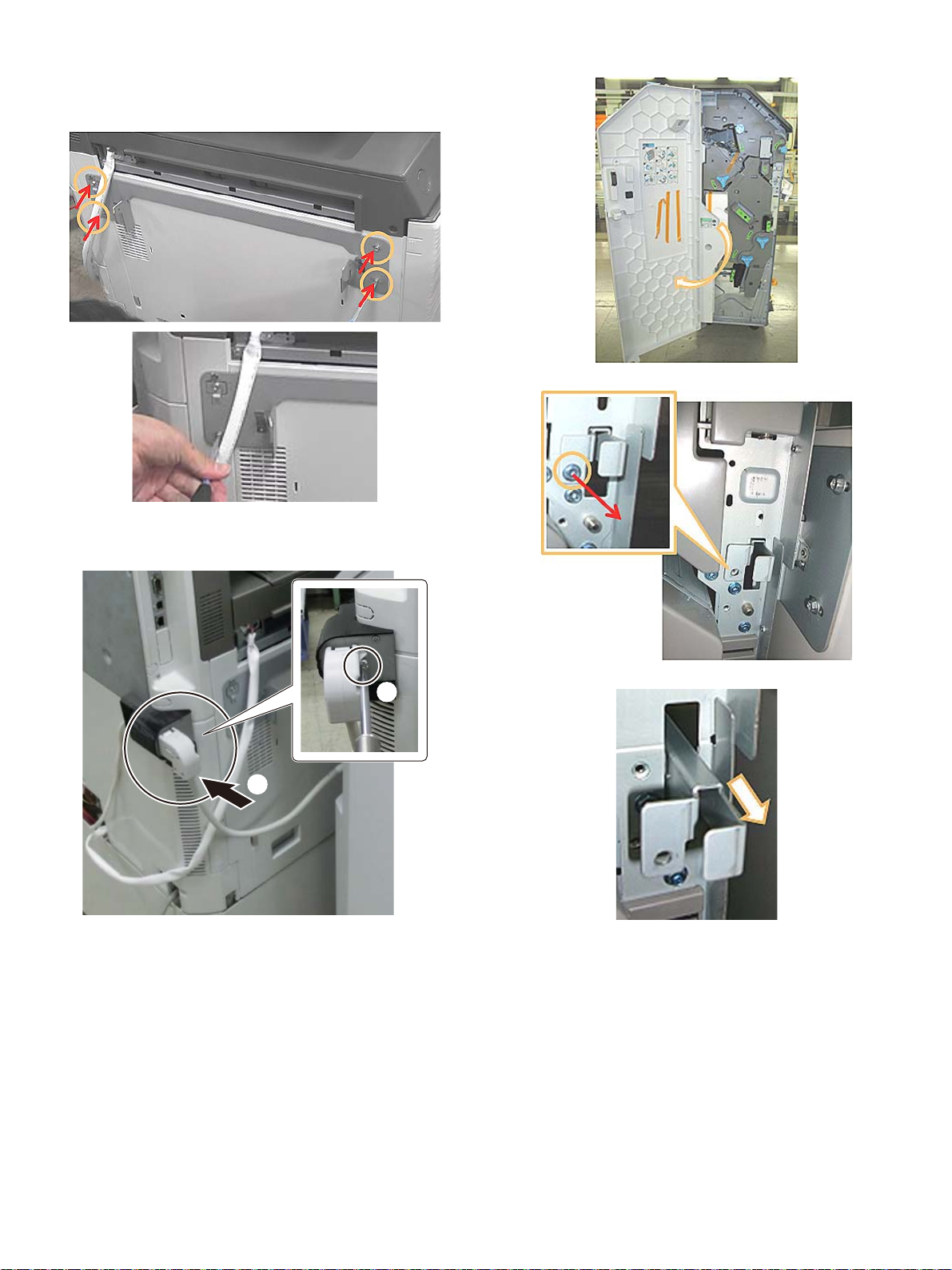
D. Installation of the bracket
Ĭ
ĭ
1) Install the bracket (Packed item No.7) with the screw (Packed
item (No.5 M4x12). Before installing the finisher, be sure to install
the interface unit.
2) Open the front cover.
3) Remove the screw fixing the finisher in the picture below.
E. Installation of the finisher
1) Attach the connector of the finisher and fix it with the screw.
Pull out the lock lever, and lower it
MX-4070N MX-FN28 (FINISHER) 10 – 3
Page 100
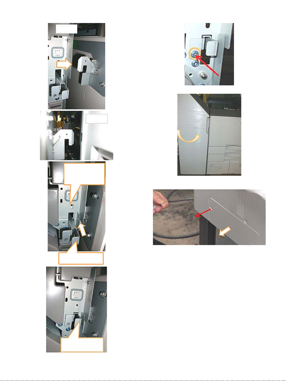
4) Bring the finisher near the main unit, and connect them. 5) Install the finisher fixing screw.
Front
Right side
Be careful not to fix
with the screw here.
Push the lock lever.
Move the lock lever to
the upper side.
6) Close the front cover of the finisher.
7) Unscrew the screw of the connector cover of the man unit, and
remove the connector cover.
MX-4070N MX-FN28 (FINISHER) 10 – 4
 Loading...