

Page 1

Technical Reference
Lexmark and Lexmark with diamond design are trademarks of Lexmark International, Inc.,
registered in the United States and/or other countries.
© 2007 Lexmark International, Inc.
740 West New Circle Road
Lexington, Kentucky 40550
www.lexmark.comMay 2007
Page 2

©
Edition: May 2007
The following paragraph does not apply to any country where such provisions are inconsistent with local law: LEXMARK
INTERNATIONAL, INC., PROVIDES THIS PUBLICATION “AS IS” WITHOUT WARRANTY OF ANY KIND, EITHER EXPRESS OR
IMPLIED, INCLUDING, BUT NOT LIMITED TO, THE IMPLIED WARRANTIES OF MERCHANTABILITY OR FITNESS FOR A PARTICULAR
PURPOSE. Some states do not allow disclaimer of express or implied warranties in certain transactions; therefore, this statement may not
apply to you.
This publication could include technical inaccuracies or typographical errors. Changes are periodically made to the information herein; these
changes will be incorporated in later editions. Improvements or changes in the products or the programs described may be made at any time.
Comments about this publication may be addressed to Lexmark International, Inc., Department F95/032-2, 740 West New Circle Road,
Lexington, Kentucky 40550, U.S.A. In the United Kingdom and Eire, send to Lexmark International Ltd., Marketing and Services
Department, Westhorpe House, Westhorpe, Marlow Bucks SL7 3RQ. Lexmark may use or distribute any of the information you supply in
any way it believes appropriate without incurring any obligation to you. To obtain additional copies of publications related to this product, visit
the Lexmark Web site at www.lexmark.com.
References in this publication to products, programs, or services do not imply that the manufacturer intends to make these available in all
countries in which it operates. Any reference to a product, program, or service is not intended to state or imply that only that product,
program, or service may be used. Any functionally equivalent product, program, or service that does not infringe any existing intellectual
property right may be used instead. Evaluation and verification of operation in conjunction with other products, programs, or services, except
those expressly designated by the manufacturer, are the user’s responsibility.
Lexmark, Lexmark with diamond design, MarkNet, MarkVision, and Optra are trademarks of Lexmark International, Inc., registered in the
United States and/or other countries. ColorGrade, PerfectFinish, and PictureGrade are trademarks of Lexmark International, Inc.
The following terms are trademarks or registered trademarks of other companies:
Albertus The Monotype Corporation plc
Antique Olive Monsieur Marcel OLIVE
Apple-Chancery Apple Computer, Inc.
Arial The Monotype Corporation plc
Candid Agfa Corporation
CG Omega Product of Agfa Corporation
CG Times Based on Times New Roman under
license
from The Monotype Corporation plc, is a
product of Agfa Corporation
Chicago Apple Computer, Inc.
Clarendon Linotype-Hell AG and/or its subsidiaries
Eurostile Nebiolo
Geneva Apple Computer, Inc.
GillSans The Monotype Corporation plc
Helvetica Linotype-Hell AG and/or its subsidiaries
Hoefler Jonathan Hoefler Type Foundry
PCL® is a registered trademark of the Hewlett-Packard Company. PCL 5 and PCL 6 are Hewlett-Packard Company’s designations of a set
of printer commands (language) and functions included in its printer products. These printers are intended to be compatible with the PCL 5
and PCL 6 languages. This means these printers recognize PCL 5 and PCL 6 commands used in various application programs, and that
the printer emulates the functions corresponding to the commands.
Other trademarks are the property of their respective owners.
ITC Avant Garde Gothic International Typeface Corporation
ITC Bookman International Typeface Corporation
ITC Lubalin Graph International Typeface Corporation
ITC Mona Lisa International Typeface Corporation
ITC Zapf Chancery International Typeface Corporation
Joanna The Monotype Corporation plc
Marigold Arthur Baker
Monaco Apple Computer, Inc.
New York Apple Computer, Inc.
Oxford Arthur Baker
Palatino Linotype-Hell AG and/or its subsidiaries
Stempel Garamond Linotype-Hell AG and/or its subsidiaries
Taffy Agfa Corporation
Times New Roman The Monotype Corporation plc
TrueType Apple Computer, Inc.
Univers Linotype-Hell AG and/or its subsidiaries
Wingdings Microsoft Corporation
1998, 2007 Lexmark International, Inc.
All rights reserved.
UNITED STATES GOVERNMENT RIGHTS
This software and any accompanying documentation provided under this agreement are commercial computer software and documentation
developed exclusively at private expense.
Page 3

Contents
Introduction ......................................................................1-1
Overview.............................................................................................................1-1
Navigational Tips................................................................................................1-4
Printing the File...................................................................................................1-4
Bibliography........................................................................................................1-5
PCL Emulation..................................................................2-1
TOC-1
Contents
Selecting PCL Emulation....................................................................................2-1
Using SmartSwitch........................................................................................2-1
Using the Operator Panel or MarkVision Professional..................................2-1
Using Your Software Program ......................................................................2-2
Page Formatting.................................................................................................2-3
Printable Areas..............................................................................................2-3
Lexmark™ E120, E120n, E238, E240, E240n, E250d,
E250dn, E340, E342n, E350d, E352dn, E450dn.......................................... 2-4
Print Area Menu Item..........................................................................................2-6
Font and Symbol Set Support for the Lexmark E120, E120n,
E238, E240, E240n, E250d, E250dn, E340, E342n, E350d,
E352dn, and E450dn..........................................................................................2-8
Forward and Backward Compatibility Modes for the
Lexmark E238, E240, E240n, E250d, E250dn, E340,
E342n, E350d, E352dn, and E450dn............................................................2-9
Selecting Symbol Sets for Lexmark E120, E120n,
E238, E240, E240n, E250d, E250dn, E340,
E342n, E350d, E352dn, E450dn.................................................................2-14
Command Structure .........................................................................................2-48
Control Codes .............................................................................................2-48
Commands..................................................................................................2-49
PCL Emulation Commands ..............................................................................2-51
PCL Emulation Commands by Function ..................................................... 2-52
GL/2 Commands ..............................................................................................2-74
Raster Image Graphics.....................................................................................2-78
Raster Compression Mode .........................................................................2-78
Page 4

TOC-2
Macros..............................................................................................................2-85
Contents
Printer Job Language ......................................................3-1
PJL Command Notation .....................................................................................3-1
Kernel Commands..............................................................................................3-2
Job Separation Commands................................................................................ 3-4
Environment Commands and Variables ............................................................. 3-7
Common Variables for PCL Emulation .......................................................3-48
Status Readback Commands...........................................................................3-54
Status Message Format ...................................................................................3-61
Information Messages.................................................................................3-61
Auto-Continuable Conditions ......................................................................3-63
Attendance Conditions................................................................................ 3-67
Operator Intervention - Paper Handling ...................................................... 3-72
Operator Intervention - Paper Jams............................................................3-75
Service Errors .............................................................................................3-80
Device Attendance Commands ........................................................................ 3-80
Unique PJL Commands....................................................................................3-82
File Commands for Flash or Disk................................................................3-86
File and Device Protection Commands ............................................................ 3-93
Protecting a File or Device.......................................................................... 3-93
Unlocking a Protected File or Device ..........................................................3-95
Re-Locking a Protected File or Device........................................................3-96
Unlocking a Protected File or Device for the Current Job ...........................3-97
Recovering Lost Passwords........................................................................3-98
PostScript Emulation.......................................................4-1
Selecting PostScript Emulation ..........................................................................4-1
Using SmartSwitch........................................................................................4-1
Using the Operator Panel or MarkVision Professional..................................4-1
Using Your Software Program ......................................................................4-2
Paper Tray Support.......................................................................................4-5
Envelope Size Support................................................................................4-10
Envelope Tray Support ...............................................................................4-12
Supplemental Operator Summary...............................................................4-14
Page Device Parameters..................................................................................4-49
Page 5

TOC-3
Interpreter Parameters .....................................................................................4-63
User Parameters.........................................................................................4-63
System Parameters.....................................................................................4-66
Device Parameters......................................................................................4-72
Status and Error Messages.............................................................................. 4-93
Tagged Binary Not Active ...........................................................................4-93
Tagged Binary Active.................................................................................. 4-93
Status Messages.........................................................................................4-94
Contents
Switching Languages ......................................................5-1
SmartSwitch .......................................................................................................5-1
Setting SmartSwitch for Different Interfaces .................................................5-2
Printer Job Language .........................................................................................5-2
Sniffing................................................................................................................5-3
Flash Memory and Disk ...................................................6-1
Resource Data Collection (Download Target) .................................................... 6-2
Storing Resources on Flash Memory or Disk................................................6-3
Viewing the Contents of Flash Memory and Disk...............................................6-3
Password Protection...........................................................................................6-7
Rewriting the Flash Content ...............................................................................6-8
Accessing Files with PostScript Emulation.........................................................6-9
File Naming Conventions .............................................................................. 6-9
Device Search Order...................................................................................6-12
Performance..................................................................................................... 6-13
Job Buffering ....................................................................................................6-13
Creating a Partition .....................................................................................6-14
Enabling Job Buffering................................................................................ 6-14
Disabling Job Buffering ...............................................................................6-15
Recovering from a Power Loss ...................................................................6-15
Printer Specifications ......................................................7-1
Airflow Requirement......................................................................................7-1
Noise Emission Levels .................................................................................. 7-1
Page 6

TOC-4
Electrical Specifications ................................................................................7-2
Power Requirements.....................................................................................7-3
Physical Specifications..................................................................................7-5
Clearance Requirements .............................................................................7-6
Environmental Conditions .............................................................................7-7
Altitude Specifications ................................................................................... 7-7
Atmospheric Pressure...................................................................................7-7
Contents
Printer Interfaces..............................................................8-1
Setting Up the Communications Port .................................................................8-2
Setting Up the Communications Port Using Windows 95/98/Me .................. 8-2
Setting Up the Communications Port Using Windows NT 4.0 ......................8-3
Setting Up the Communications Port Using Windows 2000 ......................... 8-4
Setting Up the Communications Port Using Windows XP ............................8-5
Deciding Which Interface to Use ........................................................................8-6
Parallel Interface.................................................................................................8-7
Standard Parallel Connector.........................................................................8-8
Using the INIT* Signal to Initialize.................................................................8-8
Computer-to-Printer Communications...........................................................8-8
Printer-to-Computer Communication (Advanced Status)............................8-13
Parallel Mode 1 ...........................................................................................8-14
Parallel Mode 2 ...........................................................................................8-15
Signal Descriptions .....................................................................................8-15
Using the RS-232C Serial Interface ............................................................8-21
Network Support...............................................................................................8-30
Input Buffer.......................................................................................................8-31
Page 7

TOC-5
PCL Support .................................................................... A-1
PJL Support..................................................................... B-1
PostScript Support ......................................................... C-1
Contents
Index................................................................................. X-1
Page 8
1-1
CHAPTER 1: Introduction
Overview
The following edition of the Technical Reference contains information about printer
commands and printer languages supported by the following Lexmark printers:
• Lexmark E120, E120n, E238, E240, E240n, E250d, E250dn, E340, E342n, E350d,
E352dn, E450dn
Introduction
To determine which commands and languages your printer supports, see the
appendixes in the back of this document or see your printer documentation.
If your printer is not included in this edition of the Technical Reference, it may be
available in another version. Visit the Lexmark Web site at www.lexmark.com/
publications for more information.
Table 1-1: Technical Reference Documentation Available in Hard Copy
If you need a Technic al R efere nce for the... Order Lexmark part number...
Optra™ K 11A4079
Optra N 11A9979
Optra SC 11C0905
Optra E310 12A2194
The Technical Reference is divided into the following:
Chapter 2: “PCL Emulation”
Shows how to select PCL emulation and discusses PCL emulation commands, GL/2
commands, and resident font and symbol set support.
Page 9

1-2
Chapter 3: “Printer Job Language”
Contains detailed information about certain commands that cause the printer to enter
PCL emulation, PostScript emulation, and Personal Printer Data Stream (PPDS), and
many other types of commands.
Chapter 4: “PostScript Emulation”
Provides information about PostScript emulation and explains PostScript emulation
supplemental operators.
Chapter 5: “Switching Languages”
Describes ways to switch printer languages and explains when you may want to
choose one method over another.
Introduction
Chapter 6: “Flash Memory and Disk”
Provides information about using the flash memory and hard disk. It describes how to
manage printer memory, store resources (such as fonts and macros), and manage
files.
Chapter 7: “Printer Specifications”
Lists printer specifications, including information about hardware and environmental
conditions.
Chapter 8: “Printer Interfaces”
Provides information on printer interfaces, including information about parallel and
serial interface, network support, and communication protocols.
See the tables in the three appendixes to determine if your printer supports a
particular PCL emulation, PJL, or PostScript emulation command. The appendixes
are:
Page 10

1-3
Appendix A: “PCL Support”
Appendix B: “PJL Support”
Appendix C: “PostScript Support”
Introduction
Page 11

Navigational Tips
If you are not familiar with PDF files, the following tips may help you find the
information you need.
• To move forward and backward through this document:
– Select an option under View in the menu bar at the top of the page.
– Use the arrows in the toolbar at the top of the page, or the up arrow and
down arrow keys on the keyboard.
– Press the Page Up and Page Down keys on the keyboard.
– Use the scroll bar to the right of the page.
– Click the page number box on the status bar at the bottom of the page and
type the page you want.
1-4
Introduction
• To increase or decrease the magnification of the pages:
– Select the magnifying glass icon on the toolbar at the top of the page and
– Click the magnification box on the status bar and select an option from the
• To jump directly to a particular section or key word in this document:
– Click one of the bookmarks in the overview window to the left of the page.
– Click a topic in the table of contents.
– Select Tools from the menu bar and then choose Find or Search.
– Click the binoculars icon on the toolbar and then type a word in the text box.
– Click a cross-reference to a figure, page number, or heading in the docu-
Printing the File
then draw a box around the area you want to view.
drop-down menu.
ment itself.
Although this book was designed primarily for online viewing, you can print a hard
copy by clicking File on the toolbar, and then choosing Print. Make sure you’ve
selected the correct printer, range of pages, and number of copies before you click OK.
You should be aware that if you print this document on a color printer, the color you
see on the paper may not match the color you see on your computer monitor.
Page 12

Bibliography
For detailed information about PCL emulation printer commands, PostScript
emulation printer commands and operators, and interfaces, see the following
documentation:
1-5
Introduction
• Hewlett-Packard DeskJet Printer Family Technical Reference, C2121-90101
• Hewlett-Packard LaserJet 4 Typography and Graphics, Random House
Electronic Publishing
• Hewlett-Packard PCL 5 Printer Language Technical Reference Manual,
5961-0509
• Hewlett-Packard PostScript SIMM Technical Reference, I/O Device Operators
and Parameters, C2080-90921
• Hewlett-Packard Printer Job Language Technical Reference Manual,
5961H0512
• IBM Personal System/2 Hardware Interface Technical Reference, S68X-2330
• Interface between Data Terminal Equipment and Data Communications
Equipment Employing Serial Binary Data Interchange, Electronic Industries
Association, publications EIA RS-232C and EIA\TIA-232-E
• Network Printing Alliance Protocol, A Printer/Host Control Specification
Developed by the NPA, Level 1, Revision N
• PostScript Language Reference Manual (Third Edition), Adobe Systems
Incorporated, Addison-Wesley Publishing
Page 13

2-1
CHAPTER 2: PCL Emulation
When you select PCL emulation as the printer language, the printer supports the
Hewlett-Packard Company’s LaserJet Printer Command Language. This chapter
shows how to select PCL emulation and discusses PCL emulation commands, along
with resident PCL emulation font and symbol set support.
To determine which commands your printer supports, see Appendix A: “PCL Support”
on page A-1.
PCL
Selecting PCL Emulation
Using SmartSwitch
When SmartSwitch is enabled for both printer languages on an interface (for example,
Parallel, USB, Serial Option 1, or Network Option 1), the printer automatically switches
to the printer language being sent by your software program. The printer is shipped
with SmartSwitch enabled for both printer languages in all interfaces. The printer
examines all print jobs and switches dynamically between PostScript emulation and
PCL emulation.
Using the Operator Panel or MarkVision Professional
If SmartSwitch is set to Off for both printer languages, you can select PCL emulation
from your printer operator panel or from MarkVision™ Professional. See your printer
documentation for information on changing menu settings.
Page 14

Using Your Software Program
To select PCL emulation, use the Printer Job Language (PJL) Enter Language
Command. See “ENTER LANGUAGE Command” on page 3-3 for more information.
See “Printer Job Language” on page 3-1 for the syntax and use of PJL.
Warning: When you change printer languages, you may lose some or all previously
downloaded resources, unless
are stored in flash memory or on disk.
2-2
Resource Save is set to On or the resources
PCL
Page 15
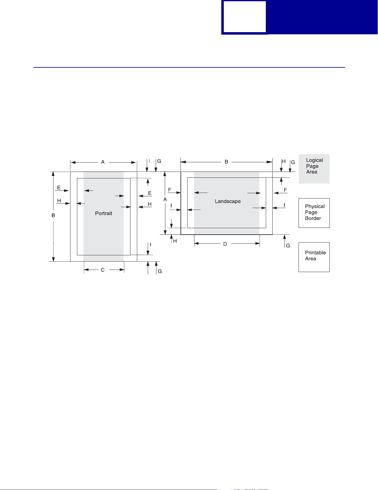
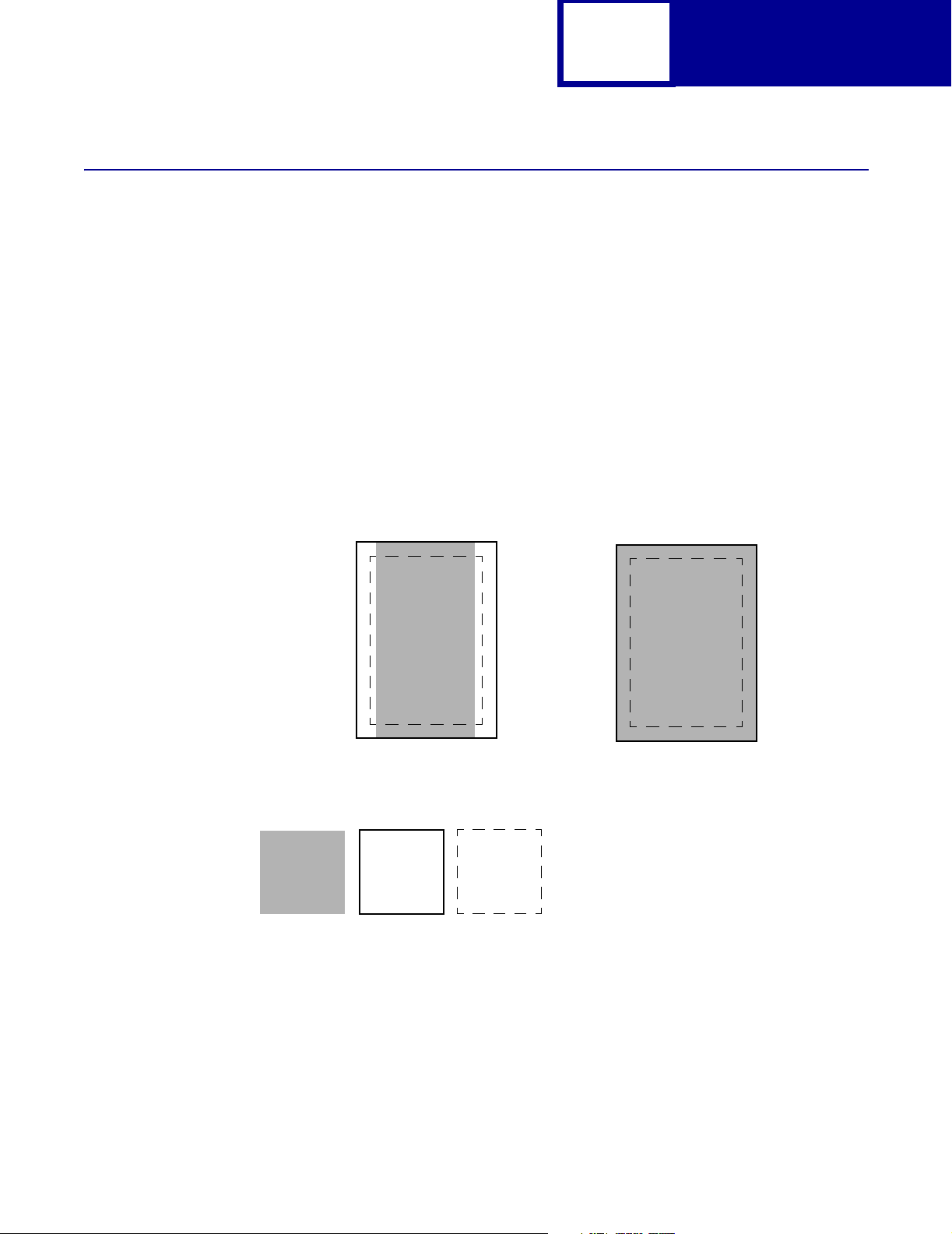
Page Formatting
The printable areas and logical pages for PCL emulation (both portrait and landscape
orientation) are illustrated below. See the Legend that follows for definitions of areas
A through I.
Printable Areas
2-3
PCL
Legend:
A Portrait physical page width and landscape physical page length
B Portrait physical page length and landscape physical page width
C Portrait logical page width
D Landscape logical page width
E Distance between the side edge of the physical page and the logical page in portrait
F Distance between the side edge of the physical page and the logical page in landscape
G Distance between the top and bottom edge of the physical page and logical page
H Distance between the left and right edge of the physical page and the printable area in
portrait, or distance between the top and bottom edge of the physical page and printable
area in landscape
I Distance between the top and bottom edge of the physical page and the printable area in
portrait, or distance between the left and right edge of the physical page and the
printable area in landscape
Note: The tables beginning on page 2-4 list the page sizes and dimensions of each
area labeled on the preceding diagram for all paper and envelope sizes your
printer supports. If information about your printer is not included in the
following tables, see page 1-1 for information on how to get a Technical
Reference for your printer.
Page 16
2-4
PCL
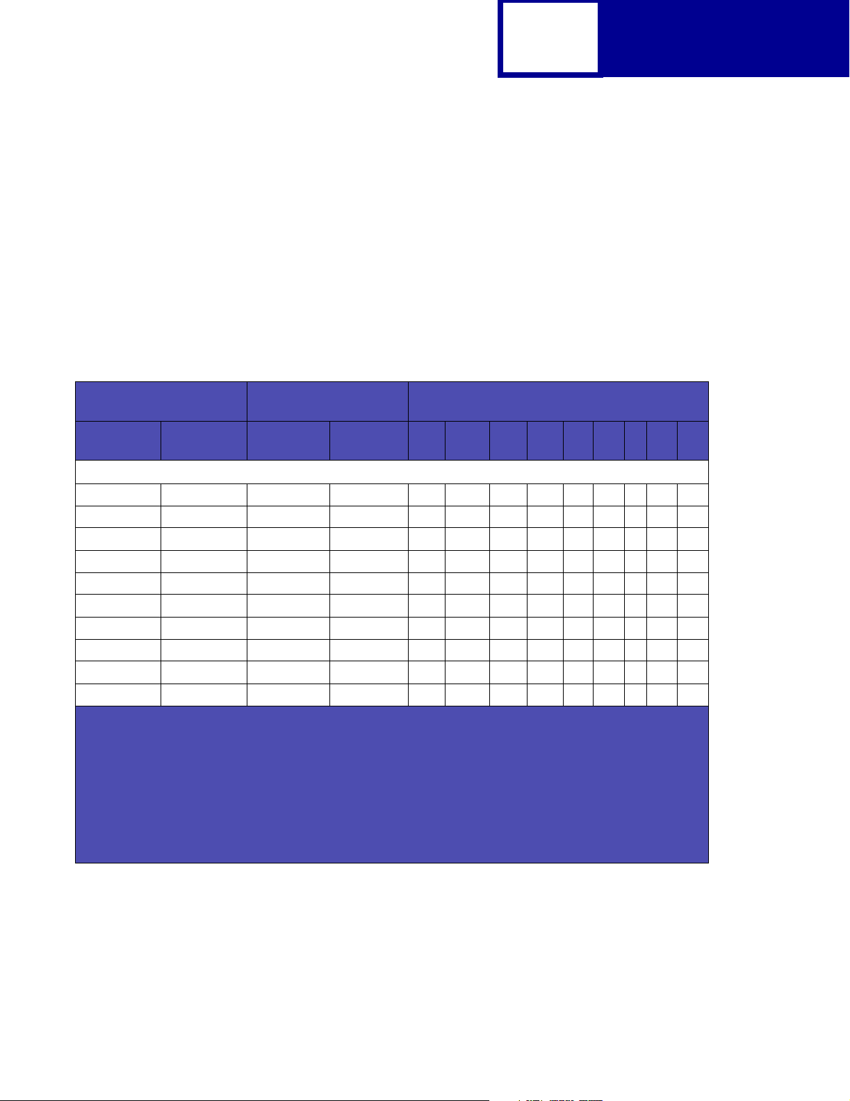
Lexmark™ E120, E120n, E238, E240, E240n, E250d, E250dn, E340, E342n, E350d, E352dn, E450dn
The following table lists page sizes and print area dimensions for all paper and
envelope sizes the Lexmark E120, E120n, E238, E240, E240n, E250d, E250dn,
E340, E342n ,E350d, E352dn, and E450dn printers support. For more information
about the printable areas and logical pages for PCL emulation, see “Printable Areas”
on page 2-3.
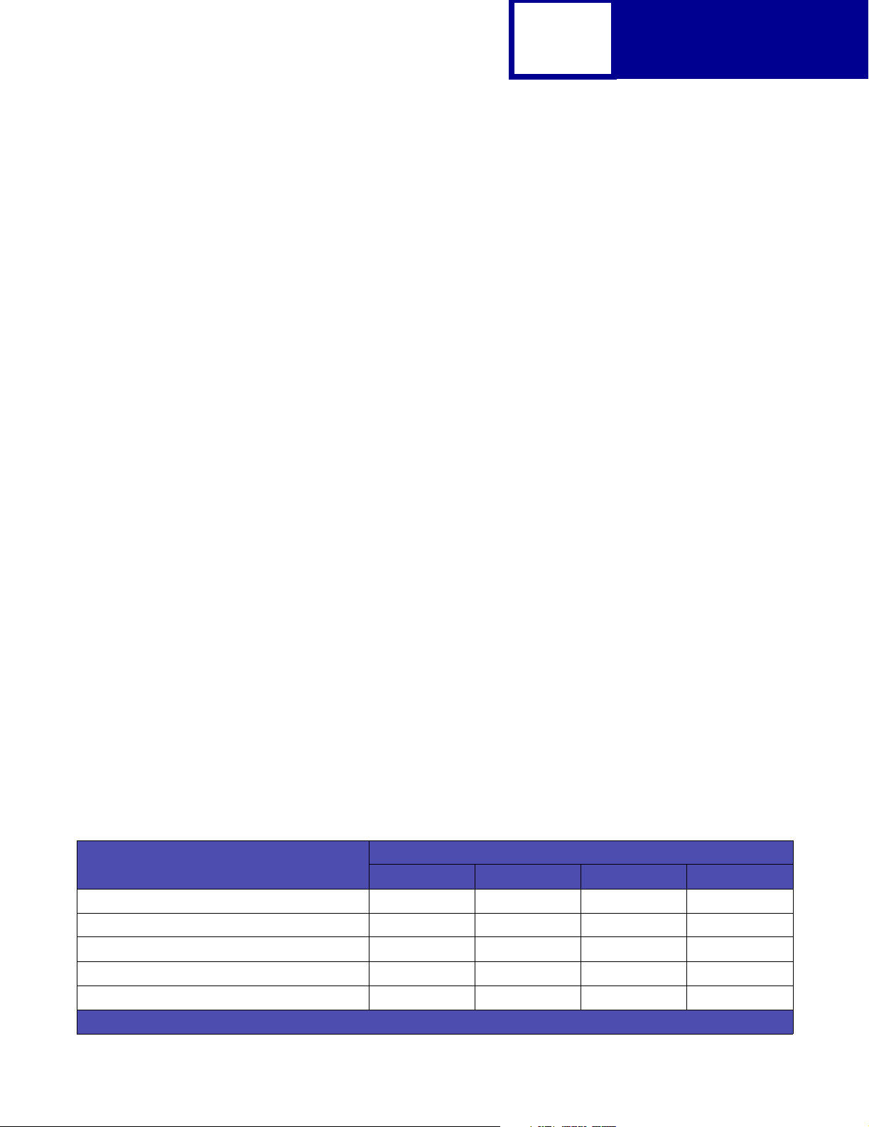
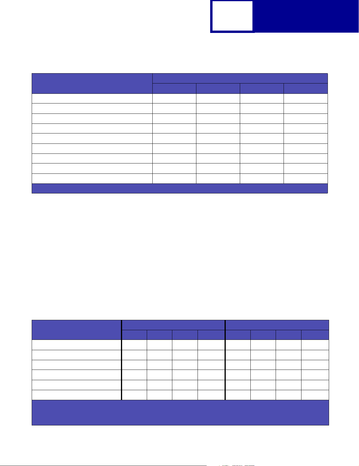
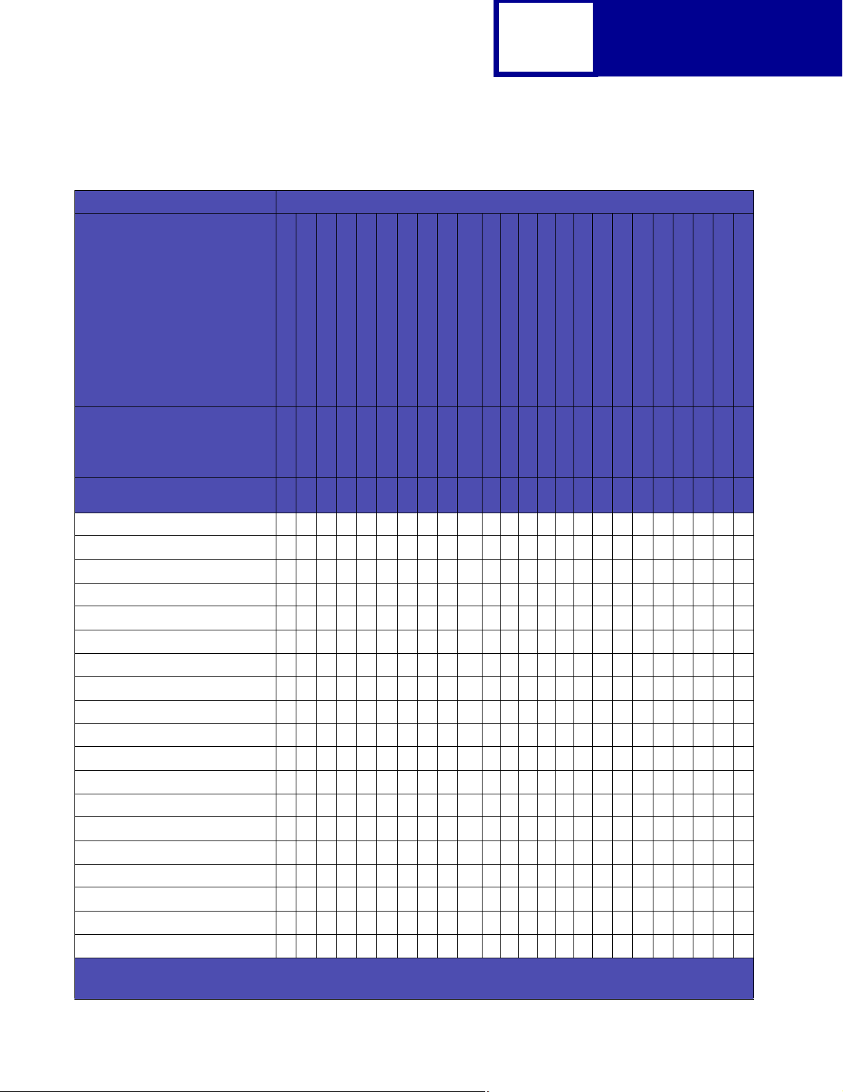
Table 2-1: Lexmark E120, E120n, E238, E240, E240n, E250d, E250dn, E340, E342n, E350d,
E352dn, E450dn Paper and Envelope Dimensions
Paper/Envelope
Selection
Page Size
Parameters2Name mm inches A B C D E F G H I
13, 613 A5 148 x 210 5.83 x 8.27 3496 4960 3196 4720 142 118 0 100 100
12, 45, 612 JIS B5 Paper 182 x 257 7.2 x 10.1 4300 6070 4000 5830 150 120 0 100 100
26, 626 A4 (198 mm)
26, 626 A4 (203 mm)
1, 601 Executive 184 x 267 7.25 x 10.5 4350 6300 4050 6060 150 120 0 100 100
2, 602 Letter 216 x 279 8.5 x 11 5100 6600 4800 6360 150 120 0 100 100
3, 603 Legal 216 x 356 8.5 x 14 5100 8400 4800 8160 150 120 0 100 100
4 or 10 Folio 216 x 330 8.5 x 13 5100 7800 4800 7560 150 120 0 100 100
15 Statement 139.7 x 215.9 5.5 x 8.5 3300 5100 3000 4860 150 120 0 100 100
101 Universal 216 x 356 8.5 x 14 150 120 0 100 100
1
Pel dimensions are for 600 dpi.
2
Page Size Parameters are explained in Table 2-16 on page 2-54.
3
The width of the logical page for A4 paper can be changed from the printer operator panel or your software
application.
4
Paper ID 99 will be supported for backward compatibility with other Lexmark printers. Paper ID 99 has the same
logical paper size as ID 100 (compatible with HP LaserJet 5Si/5SiMx) but is 8 pels wider than the Lexmark
4039.
Note: The explanation of the printable area assumes the Print Area menu item is set to Normal. For more
information, see “Print Area Menu Item” on page 2-6.
Dimensions
3
210 x 297 8.3 x 11.7 4960 7014 4676 6778 142 118 0 80 80
3
210 x 297 8.3 x 11.7 4960 7014 4800 6778 80 118 0 80 80
Dimensions by Area (pels)
Paper
1
Page 17
2-5
PCL
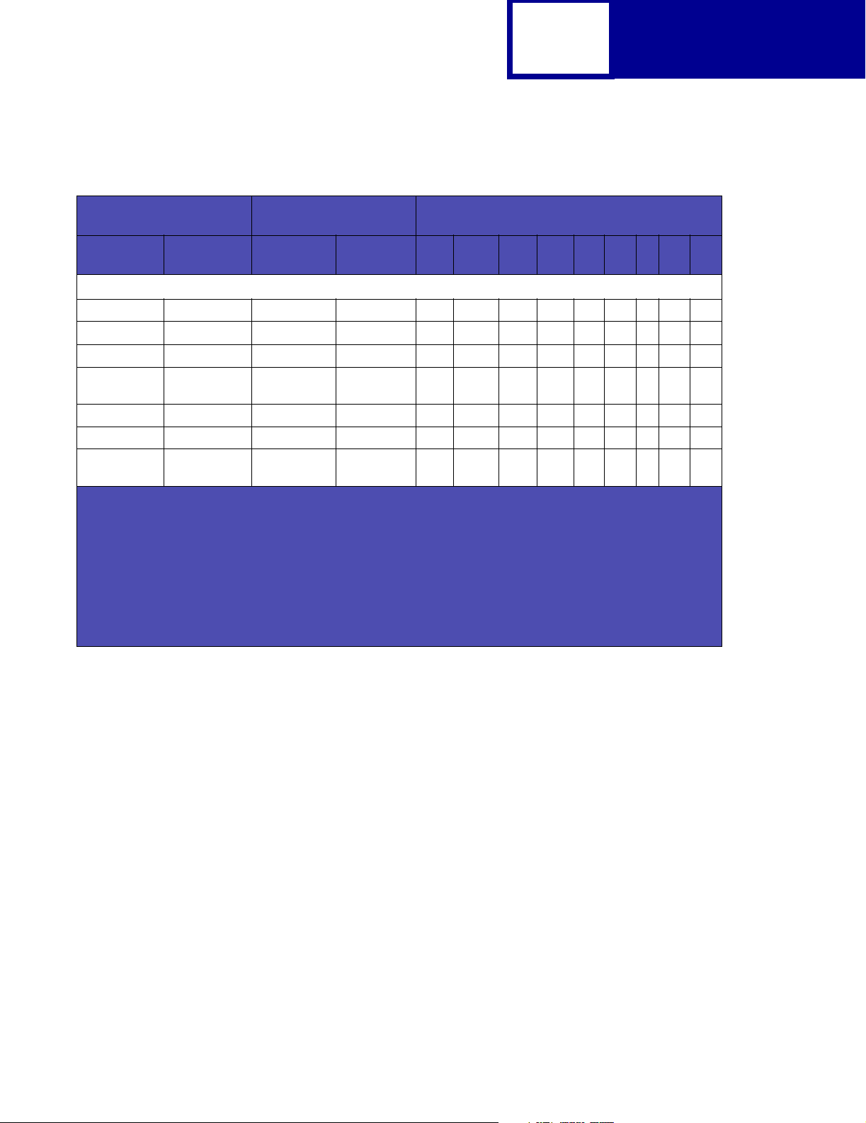
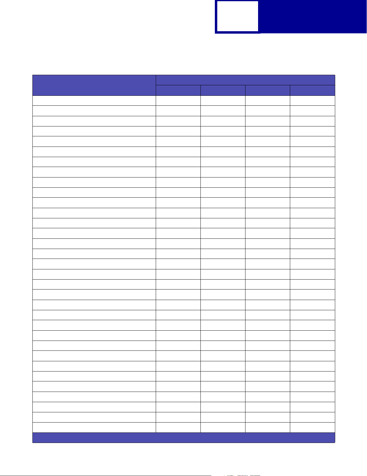
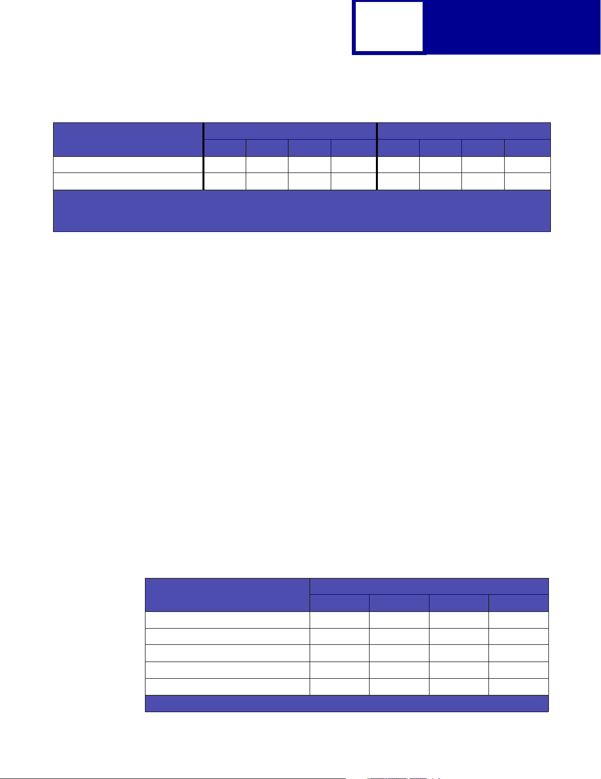
Table 2-1: Lexmark E120, E120n, E238, E240, E240n, E250d, E250dn, E340, E342n, E350d,
E352dn, E450dn Paper and Envelope Dimensions (Continued)
Paper/Envelope
Selection
Page Size
Parameters2Name mm inches A B C D E F G H I
90 DL 220 x 110 8.66 x 4.33 2598 5196 2314 4960 142 118 0 100 100
91 C5 229 x 162 9.02 x 6.38 3826 5408 2542 5172 142 118 0 100 100
4
99
, 100 B5 Envelope 250 x 176 9.84 x 6.93 4156 5904 3872 5668 142 118 0 100 100
600 Other
Envelope
89 9 (Com 9) 225 x 98 8.875 x 3.875 2326 5324 2024 5084 150 120 0 100 100
81 10 (Com 10) 241 x 105 9.5 x 4.125 2474 5700 2174 5460 150 120 0 100 100
80 7 3/4
(Monarch)
1
Pel dimensions are for 600 dpi.
2
Page Size Parameters are explained in Table 2-16 on page 2-54.
3
The width of the logical page for A4 paper can be changed from the printer operator panel or your software
application.
4
Paper ID 99 will be supported for backward compatibility with other Lexmark printers. Paper ID 99 has the same
logical paper size as ID 100 (compatible with HP LaserJet 5Si/5SiMx) but is 8 pels wider than the Lexmark
4039.
Note: The explanation of the printable area assumes the Print Area menu item is set to Normal. For more
information, see “Print Area Menu Item” on page 2-6.
Dimensions
Envelope
216 x 356 8.5 x 14 5100 8400 4800 8160 150 120 0 100 100
98 x 191 3.875 x 7.5 2326 4300 2024 4260 150 120 0 100 100
Dimensions by Area (pels)
1
Page 18
Print Area Menu Item
The printable area is the area on a sheet of paper within which a pel can be printed.
Logical page is a conceptual entity that defines the area in which margins (top, bottom,
left, right) may be set and the area in which the PCL cursor may be positioned.
The physical page border is the actual physical boundaries of a page.
The
Print Area menu item is available from the printer operator panel or through
MarkVision Professional. For some printers, Print Area supports three values: Normal,
Whole Page, and Fit to Page. See your printer documentation for more information
.
2-6
PCL
Normal setting
Legend:
PCL
Logical
Page
Area
The Normal setting, which is the factory default, means the printable area includes the
entire page except the narrow border around the edge of the page. This is the
nonprintable area. The printer measures margin settings relative to the logical page.
Physical
Page
Border
PCL
Printable
Area
Only Portrait Orientation is shown for all settings.
Whole Page setting
For a more detailed explanation of the Normal setting, see “Printable Areas” on
page 2-3.
Page 19
2-7
PCL
The Whole Page setting only affects pages printed when using PCL emulation. If
Whole Page is selected, the PCL language sets the logical page area equal to the
physical page dimensions. Since the logical page dimensions and the physical page
dimensions are the same, in theory, the cursor may be positioned anywhere on the
page. However, the PCL language clips the image to the printable area. So, the Whole
Page setting is useful for printing scanned images that extend from edge to edge of a
page.
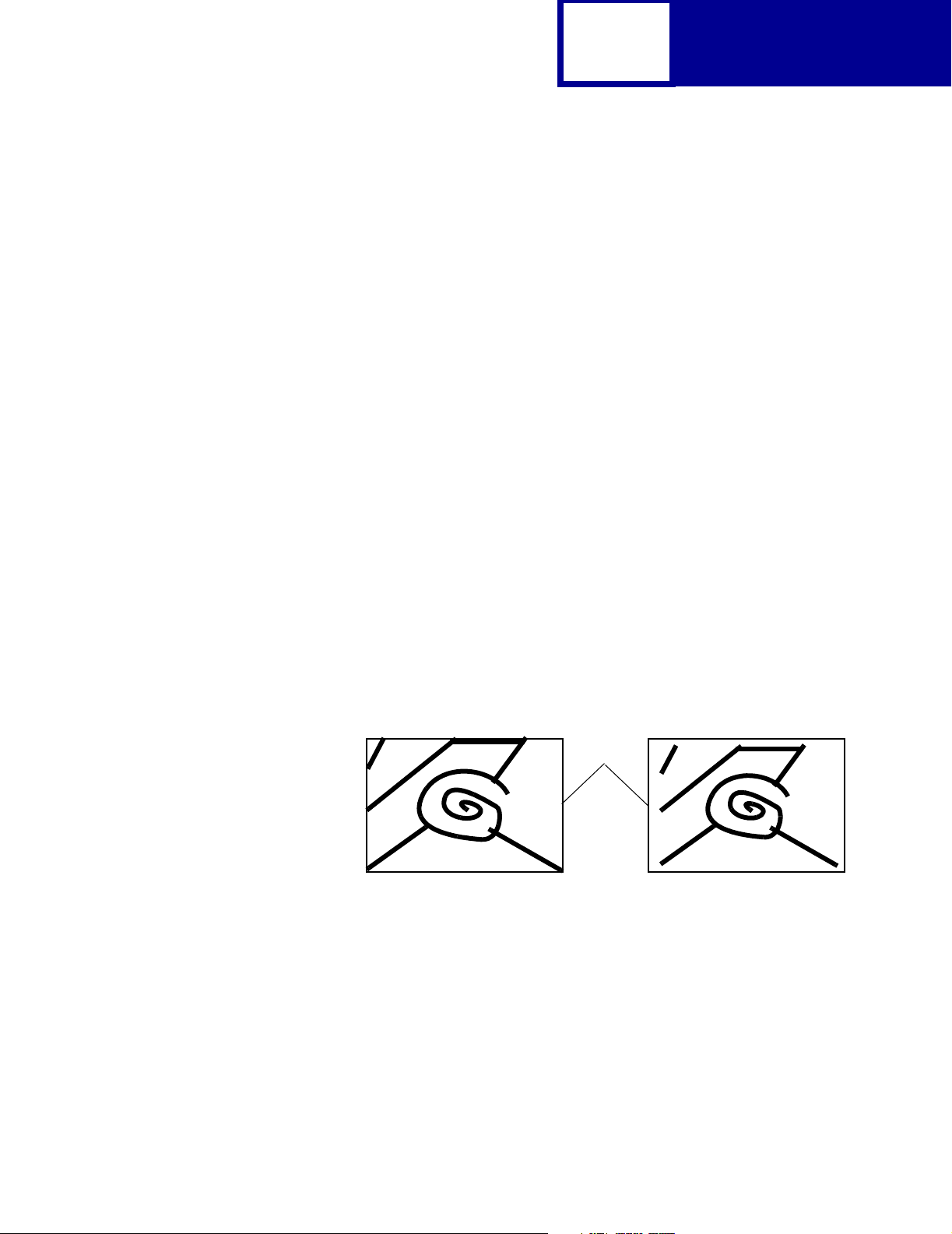
Some printers offer the Fit to Page setting. When Fit to Page is selected, PCL
emulation or PostScript emulation formats a page using a printable area equal to the
physical page, which is from one edge of the page to the other edge of the page. If you
use this setting, no clipping occurs. In Fit to Page, the PCL emulation logical page
dimensions are equal to the physical page dimensions, as in the Whole Page setting.
The printer holds this formatted image in memory, but when the page prints, the image
is compressed a small amount in both horizontal and vertical directions, and then
centered on the physical page for letter-size paper only. This process creates a small
margin around the image. This artificial margin prevents printing from one edge to the
other, since doing so could contaminate the printer and cause printing problems.
The following illustrations show an image held in memory for printing from one edge
to the other and how the image would actually print based on the Fit to Page setting.
Notice that a small border appears at the edges of the printed page, and the image is
slightly compressed.
Physical
Page
Edge
Formatted Image with Fit to Page Printed Image with Fit to Page
Page 20

2-8
PCL
Font and Symbol Set Support for the Lexmark E120,
E120n, E238, E240, E240n, E250d, E250dn, E340,
E342n, E350d, E352dn, and E450dn
Your printer has 91 resident fonts in PCL emulation, including 89 scalable fonts and
two bitmapped fonts. The E120 and E120n has 19 resident fonts including 17 scalable
fonts and two bitmapped fonts.
Several parameters are used to select a font from the data stream. These include
symbol set, spacing, point or pitch, style, weight, and typeface number. For scalable
fonts, you can vary the size of a font by specifying pitch or point size. For bitmapped
fonts, you must choose the pitch or point size listed on the font sample pages. You can
print the font sample pages using a PJL command (see “LPRINTPCLFONTS” on
page 3-83.), or through MarkVision Professional (network models only). See your
printer documentation for more information.
A symbol set defines which characters are available for a font and the code point for
each of these characters. Your printer supports 88 resident symbol sets. The tables
beginning on page 2-10 show the symbol sets available for each font in
PCL emulation. Not all fonts support all symbol sets.
You can select a font as the PCL emulation default through MarkVision Professional
(network models only). See your printer documentation for more information.
The fonts are divided into three major groups. The first 47 fonts (R0 to R46) shown on
the font sample pages are the standard PCL emulation fonts. The next 39 fonts (R47
to R85) are called Type 1 fonts and were originally defined for PostScript emulation,
but now also work in the PCL emulation. The final five fonts (R86 to R90) are additional
specialty PCL emulation fonts. For a list of the 47 standard PCL emulation fonts, see
Table 2-2 on page 2-9. For a list of the 39 Type 1 fonts, see Table 2-3 on page 2-11.
For a list of the five additional specialty PCL emulation fonts, see Table 2-11 on
page 2-43. These tables list both the forward and backward compatibility font selection
commands. For more information on forward and backward compatibility, see
page 2-9. For more information on selecting symbol sets, see page 2-38.
For compatibility purposes, you can disable Type 1 fonts with the Printer Job
Language (PJL) LTYPE1FONTS command. The factory default for these fonts is
Enabled. See LTYPE1FONTS on page 3-48 for more information.
Page 21
2-9
PCL
You can also select fonts using PJL commands. The selection parameter is the
number portion from the font identifier shown on the font sample pages, such as 0 or
76 from font identifiers R0 or R76. Use the PJL values shown in the tables beginning
on page 2-9 to select a symbol set. If a symbol set does not have a PJL value, use the
symbol set ID to select the symbol set. A font selection can be either temporary or set
as the default.
Use the following PJL commands to select fonts: FONTSOURCE, FONTNUMBER,
PITCH, PTSIZE, SYMSET, SET, DEFAULT. See “Table 3-5: Common Variables for
PCL Emulation” on page 3-48 for more information about these commands.
Forward and Backward Compatibility Modes for the
Lexmark E238, E240, E240n, E250d, E250dn, E340, E342n, E350d,
E352dn, and E450dn
Your PCL emulation has forward and backward compatibility modes. The forward
compatibility mode is used to emulate the fonts in the Hewlett-Packard Company’s
LaserJet 4050. The backward compatibility mode is used for compatibility with the
Hewlett-Packard Company’s LaserJet 5 and the Lexmark family of printers.
Note: Lexmark E120 and E120n support Backward Compatibility Modes, but not
Forward Compatibility Modes.
Standard PCL Emulation Fonts
The following table lists the font selection commands for forward and backward
compatibility mode for each of the 47 standard PCL emulation fonts. Since the font
selection commands for the forward and backward compatibility modes are identical,
they are listed together in the table.
Table 2-2: Forward and Backward Compatibility Font Selection Commands
Forward and Backward Compatibility Mode
Standard PCL Emulation Font Name
Spacing Style Weight Typeface
Courier 0 0 0 4099
Courier Italic 0 1 0 4099
Courier Bold 0 0 3 4099
Courier Bold Italic 0 1 3 4099
CG Times 1 0 0 4101
1
This font is not implemented in the Hewlett-Packard Company’s LaserJet 4050.
Page 22
2-10
Table 2-2: Forward and Backward Compatibility Font Selection Commands (Continued)
Forward and Backward Compatibility Mode
PCL
Standard PCL Emulation Font Name
CG Times Italic 1104101
CG Times Bold 1 0 3 4101
CG Times Bold Italic 1 1 3 4101
Univers Medium 1 0 0 4148
Univers Medium Italic 1 1 0 4148
Univers Bold 1 0 3 4148
Univers Bold Italic 1 1 3 4148
Times New Roman 1 0 0 16901
Times New Roman Italic 1 1 0 16901
Times New Roman Bold 1 0 3 16901
Times New Roman Bold Italic 1 1 3 16901
Arial 1 0 0 16602
Arial Italic 1 1 0 16602
Arial Bold 1 0 3 16602
Arial Bold Italic 1 1 3 16602
Letter Gothic 0 0 0 4102
Letter Gothic Italic 0 1 0 4102
Spacing Style Weight Typeface
Letter Gothic Bold 0 0 3 4102
Univers Condensed Medium 1 4 0 4148
Univers Condensed Medium Italic 1 5 0 4148
Univers Condensed Bold 1 4 3 4148
Univers Condensed Bold Italic 1 5 3 4148
Garamond Antiqua 1 0 0 4197
Garamond Kursiv 1 1 0 4197
Garamond Halbfett 1 0 3 4197
Garamond Kursiv Halbfett 1 1 3 4197
CG Omega 1 0 0 4113
CG Omega Italic 1 1 0 4113
CG Omega Bold 1 0 3 4113
CG Omega Bold Italic 1 1 3 4113
Antique Olive 1 0 0 4168
Antique Olive Italic 1 1 0 4168
Antique Olive Bold 1 0 3 4168
1
This font is not implemented in the Hewlett-Packard Company’s LaserJet 4050.
Page 23
2-11
Table 2-2: Forward and Backward Compatibility Font Selection Commands (Continued)
Forward and Backward Compatibility Mode
PCL
Standard PCL Emulation Font Name
Albertus Medium 1 0 1 4362
Albertus Extra Bold 1 0 4 4362
Clarendon Condensed Bold 1 4 3 4140
Marigold 1 0 0 4297
Coronet 1 1 0 4116
Line Printer 16 0 0 0 0
POSTNET Barcode
Wingdings 1 0 0 31402
Symbol 1 0 0 16686
1
This font is not implemented in the Hewlett-Packard Company’s LaserJet 4050.
1
Spacing Style Weight Typeface
1000
Type 1 Fonts
Thirty of the Type 1 fonts have different font selection parameters in the forward and
backward compatibility modes and nine of the fonts work only in the forward
compatibility mode. With the appropriate printer driver installed and selected, your
software program selects these fonts.
The following table shows the font selection commands for forward and backward
compatibility modes and indicates the font group for each font. All Type 1 fonts are
supported by both the Hewlett-Packard Company’s LaserJet 4050 and the
Lexmark family of printers unless otherwise noted.
Table 2-3: Forward and Backward Compatibility Font Selection Commands
Forward Compatibility Mode Backward Compatibility Mode
Type 1 Font name
Helvetica 1002458010061444
Helvetica Italic 1102458011061444
Helvetica Bold 1032458010361444
Helvetica Bold Italic 1132458011361444
Helvetica Narrow 1402458014061444
Helvetica Narrow Italic 1502458015061444
1
Notice the values for forward and backward compatibility modes differ slightly for Bold.
2
This font is not implemented in the Hewlett-Packard Company’s LaserJet 4050.
3
This font is not implemented in the Lexmark family of printers.
Spacing Style Weight Typeface Spacing Style Weight Typeface
Page 24
2-12
Table 2-3: Forward and Backward Compatibility Font Selection Commands (Continued)
Forward Compatibility Mode Backward Compatibility Mode
PCL
Type 1 Font name
Spacing Style Weight Typeface Spacing Style Weight Typeface
Helvetica Narrow Bold 1432458014361444
Helvetica Narrow Bold Italic 1532458015361444
Palatino Roman 1002459110061455
Palatino Italic 1102459111061455
Palatino Bold 1032459110361455
Palatino Bold Italic 1132459111361455
ITC Bookman Light 1 0 -3 24623 1 0 -3 61487
ITC Bookman Light Italic 1 1 -3 24623 1 1 -3 61487
ITC Bookman Demi 1022462310261487
ITC Bookman Demi Italic 1122462311261487
ITC Avant Garde Book 1002460710061471
ITC Avant Garde Book Oblique1102460711061471
ITC Avant Garde Demi
1
ITC Avant Garde Demi Oblique
1022460710361471
1
1122460711361471
Century Schoolbook Roman 1002470310061463
Century Schoolbook Italic 1102470311061463
Century Schoolbook Bold 1032470310361463
Century Schoolbook Bold Italic1132470311361463
ITC Zapf Chancery Medium Italic1104509911061483
CourierPS
CourierPS Oblique
CourierPS Bold
CourierPS Bold Oblique
Times Roman
Times Italic
Times Bold
Times Bold Italic
Helvetica Light
Helvetica Light Oblique
Helvetica Black
Helvetica Black Oblique
1
Notice the values for forward and backward compatibility modes differ slightly for Bold.
2
This font is not implemented in the Hewlett-Packard Company’s LaserJet 4050.
3
This font is not implemented in the Lexmark family of printers.
3
3
3
3
3
3
3
3
2
2
2
2
0 0 0 24579
0 1 0 24579
0 0 3 24579
0 1 3 24579
1 0 0 25093
1 1 0 25093
1 0 3 25093
1 1 3 25093
1 0 -3 24580 1 0 -3 61444
1 1 -3 24580 1 1 -3 61444
1052458010561444
1152458011561444
Page 25
2-13
Table 2-3: Forward and Backward Compatibility Font Selection Commands (Continued)
Forward Compatibility Mode Backward Compatibility Mode
PCL
Type 1 Font name
SymbolPS
ITC Zapf Dingbats 1004510110061485
1
Notice the values for forward and backward compatibility modes differ slightly for Bold.
2
This font is not implemented in the Hewlett-Packard Company’s LaserJet 4050.
3
This font is not implemented in the Lexmark family of printers.
3
Spacing Style Weight Typeface Spacing Style Weight Typeface
1 0 0 45358
Your Lexmark printer defaults to the forward compatibility mode to enable a HewlettPackard Company’s driver to select the forward compatibility fonts. The Lexmark PCL
emulation driver uses the backward compatibility mode and temporarily switches the
printer to this mode. The PCL (PJL) emulation commands to switch the default
compatibility modes are:
Forward
Backward
ESC
%-12345X@PJL DEFAULT LPARM:PCL LFONTCOMPATIBILITY=PCL6
@PJL RESET
ESC
%-12345X
ESC
%-12345X@PJL DEFAULT LPARM:PCL LFONTCOMPATIBILITY=PCL5
@PJL RESET
ESC
%-12345X
Specialty PCL Fonts
The following table lists the font selection commands for forward and backward
compatibility mode for each of the five specialty PCL emulation fonts. Since the font
selection commands for the forward and backward compatibility modes are identical,
they are listed together in the table. These fonts are supported only in PCL 5
emulation, not in PCL XL.
Table 2-4: Forward and Backward Compatibility Font Selection Commands
Standard PCL Emulation Font Name
C39 Narrow
C39 Regular
C39 Wide
1
OCR-A
1
OCR-B
1
This font is not implemented in the Hewlett-Packard Company’s LaserJet 4050.
Forward and Backward Compatibility Mode
Spacing Style Weight Typeface
1
1
1
1 0 0 32774
1 0 0 32772
1 0 0 32777
0 0 0 23584
0 0 0 23590
Page 26

2-14
PCL
Selecting Symbol Sets for Lexmark E120, E120n, E238, E240,
E240n, E250d, E250dn, E340, E342n, E350d, E352dn, E450dn
To determine if a font or typeface supports a symbol set, see the complete listing of
PCL emulation fonts and symbol sets in the following tables: “Table 2-7: Lexmark
E120, E120n, E238, E240, E240n, E250d, E250dn, E340, E342n, E350d, E352dn,
and E450dn PCL Emulation Symbol Sets - Specials” on page 2-26, “Table 2-9:
Lexmark E120, E120n, E238, E240, E240n, E250d, E250dn, E340, E342n, E350d,
E352dn, and E450dn PCL Emulation Symbol Sets - Latin 1” on page 2-31, and
“Table 2-11: Lexmark E120, E120n, E238, E240, E240n, E250d, E250dn, E340,
E342n, E350d, E352dn, and E450dn PCL Emulation Symbol Sets - Specials” on
page 2-43.
Selecting Symbol Sets for the Lexmark E120, E120n, E238, E240,
E240n, E250d, E250dn, E340, E342n, E350d, E352dn, and E450dn
To determine if a font or typeface supports a symbol set, see the complete listing of
PCL emulation fonts and symbol sets in the following tables: “Table 2-7: Lexmark
E120, E120n, E238, E240, E240n, E250d, E250dn, E340, E342n, E350d, E352dn,
and E450dn PCL Emulation Symbol Sets - Specials” on page 2-26, “Table 2-10:
Lexmark E120, E120n, E238, E240, E240n, E250d, E250dn, E340, E342n, E350d,
E352dn, and E450dn PCL Emulation Symbol Sets - Latin 2, Latin 5, Latin 6, Cyrillic,
Page 27
2-15
PCL
Greek” on page 2-37, and “Table 2-11: Lexmark E120, E120n, E238, E240, E240n,
E250d, E250dn, E340, E342n, E350d, E352dn, and E450dn PCL Emulation Symbol
Sets - Specials” on page 2-43
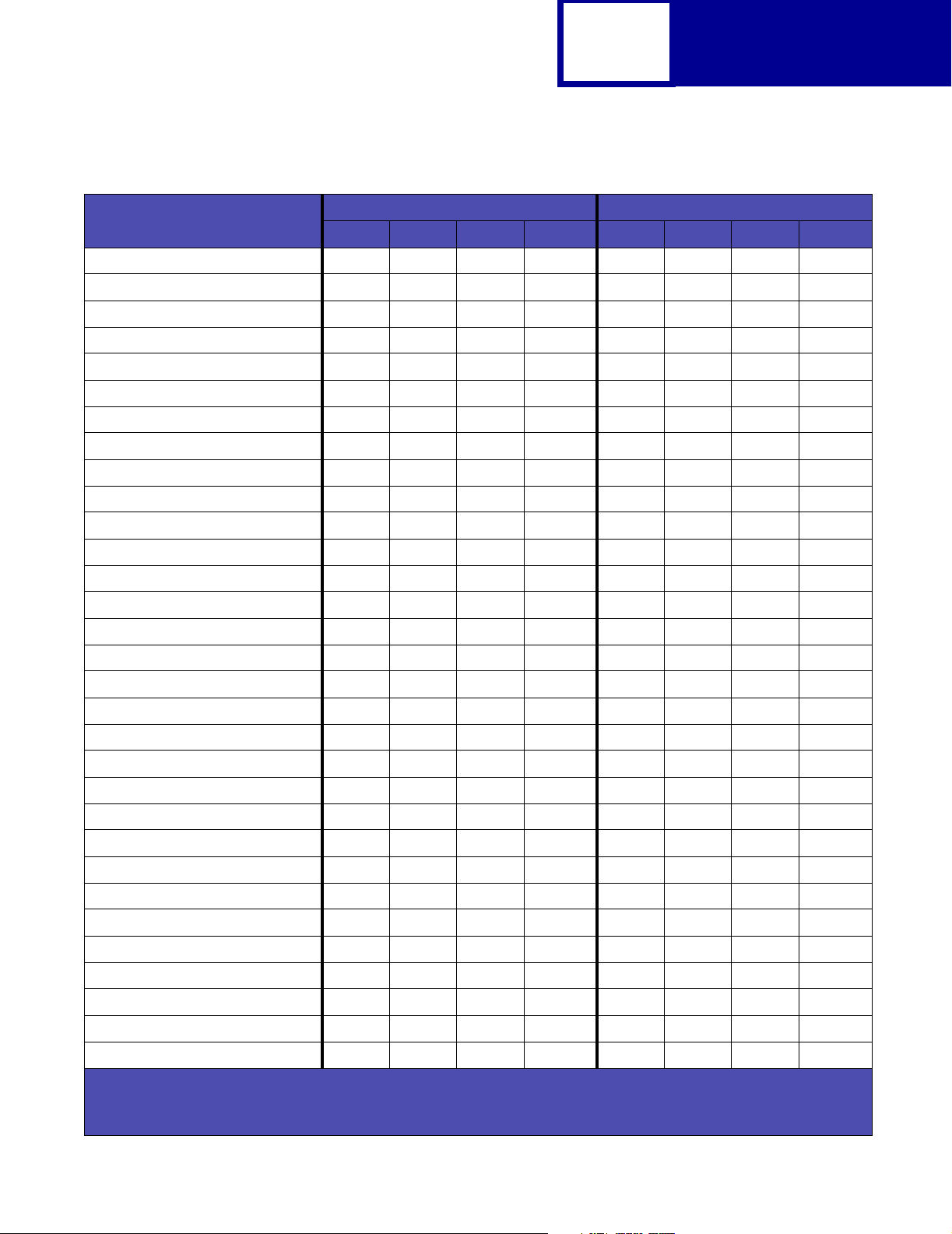
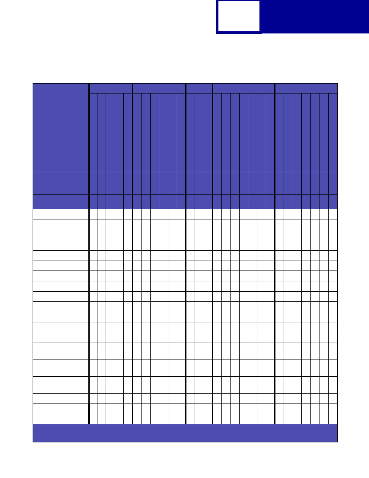
Table 2-5: Lexmark E120, E120n, E238, E240, E240n, E250d, E250dn, E340, E342n, E350d,
E352dn, and E450dn PCL Emulation Symbol Sets - Latin 1
Latin 1
Typeface / Symbol Set
PJL Value
Symbol Set ID
Courier ✓✓✓✓✓✓✓✓✓ ✓ ✓✓✓✓✓✓✓ ✓ ✓✓✓✓✓✓
Courier Italic ✓✓✓✓✓✓✓✓✓ ✓ ✓✓✓✓✓✓✓ ✓ ✓✓✓✓✓✓
Courier Bold ✓✓✓✓✓✓✓✓✓ ✓ ✓✓✓✓✓✓✓ ✓ ✓✓✓✓✓✓
Courier Bold Italic ✓✓✓✓✓✓✓✓✓ ✓ ✓✓✓✓✓✓✓ ✓ ✓✓✓✓✓✓
CG Times ✓✓✓✓✓✓✓✓✓ ✓ ✓✓✓✓✓✓✓ ✓ ✓✓✓✓✓✓
CG Times Italic ✓✓✓✓✓✓✓✓✓ ✓ ✓✓✓✓✓✓✓ ✓ ✓✓✓✓✓✓
CG Times Bold ✓✓✓✓✓✓✓✓✓ ✓ ✓✓✓✓✓✓✓ ✓ ✓✓✓✓✓✓
CG Times Bold Italic ✓✓✓✓✓✓✓✓✓ ✓ ✓✓✓✓✓✓✓ ✓ ✓✓✓✓✓✓
Univers Medium ✓✓✓✓✓✓✓✓✓ ✓ ✓✓✓✓✓✓✓ ✓ ✓✓✓✓✓✓
Univers Medium Italic ✓✓✓✓✓✓✓✓✓ ✓ ✓✓✓✓✓✓✓ ✓ ✓✓✓✓✓✓
Univers Bold ✓✓✓✓✓✓✓✓✓ ✓ ✓✓✓✓✓✓✓ ✓ ✓✓✓✓✓✓
Univers Bold Italic ✓✓✓✓✓✓✓✓✓ ✓ ✓✓✓✓✓✓✓ ✓ ✓✓✓✓✓✓
Times New Roman ✓✓✓✓✓✓✓✓✓ ✓ ✓✓✓✓✓✓✓ ✓ ✓✓✓✓✓✓
Legal
Windows 3.0 Latin 1
LEGAL
WIN30
1U9U19U
Windows 98 Latin 1
ISO 8859-1 Latin 1 (ECMA-94)
WINL1
ISOL1
0N9N10U
ISO 8859-15 Latin 9
ISOL9
PC-8, Code Page 437
PC8
PC-8 Danish/Norwegian (437N)
PC-850 Multilingual
PC8DN
PC850
11U
12U
PC-858 Multilingual Euro
PC-860 Portugal
PC858
13U
20U
PC-861 Iceland
PC-863 Canadian French
21U
23U
PC-865 Nordic
25U
PC-1004 OS/2
ABICOMP Brazil/Portugal
ABICOMP International
Roman-8
Roman-9
ROMAN8
9J
13P
14P
8U4U0E
Roman Extension
PS Text
MC Text
PSTEXT
10J
12J
Desk Top
DESKTOP
7J
Ventura International
VNINTL
13J
Ventura US
VNUS
14J
Times New Roman Italic ✓✓✓✓✓✓✓✓✓ ✓ ✓✓✓✓✓✓✓ ✓ ✓✓✓✓✓✓
Times New Roman Bold ✓✓✓✓✓✓✓✓✓ ✓ ✓✓✓✓✓✓✓ ✓ ✓✓✓✓✓✓
Times New Roman Bold Italic ✓✓✓✓✓✓✓✓✓ ✓ ✓✓✓✓✓✓✓ ✓ ✓✓✓✓✓✓
✓ Indicates Typeface supports the specified Symbol Set.
✘ Indicates Typeface does not support the specified Symbol Set.
Page 28

2-16
PCL
Table 2-5: Lexmark E120, E120n, E238, E240, E240n, E250d, E250dn, E340, E342n, E350d,
E352dn, and E450dn PCL Emulation Symbol Sets - Latin 1 (Continued)
Latin 1
Typeface / Symbol Set
PJL Value
Symbol Set ID
Arial ✓✓✓✓✓✓✓✓✓ ✓ ✓✓✓✓✓✓✓ ✓ ✓✓✓✓✓✓
Arial Italic ✓✓✓✓✓✓✓✓✓ ✓ ✓✓✓✓✓✓✓ ✓ ✓✓✓✓✓✓
Arial Bold ✓✓✓✓✓✓✓✓✓ ✓ ✓✓✓✓✓✓✓ ✓ ✓✓✓✓✓✓
Arial Bold Italic ✓✓✓✓✓✓✓✓✓ ✓ ✓✓✓✓✓✓✓ ✓ ✓✓✓✓✓✓
Letter Gothic ✓✓✓✓✓✓✓✓✓ ✓ ✓✓✓✓✓✓✓ ✓ ✓✓✓✓✓✓
Letter Gothic Italic ✓✓✓✓✓✓✓✓✓ ✓ ✓✓✓✓✓✓✓ ✓ ✓✓✓✓✓✓
Letter Gothic Bold ✓✓✓✓✓✓✓✓✓ ✓ ✓✓✓✓✓✓✓ ✓ ✓✓✓✓✓✓
Univers Condensed Medium ✓✓✓✓✓✓✓✓✓ ✓ ✓✓✓✓✓✓✓ ✓ ✓✓✓✓✓✓
Univers Condensed Medium Italic ✓✓✓✓✓✓✓✓✓ ✓ ✓✓✓✓✓✓✓ ✓ ✓✓✓✓✓✓
Univers Condensed Bold ✓✓✓✓✓✓✓✓✓ ✓ ✓✓✓✓✓✓✓ ✓ ✓✓✓✓✓✓
Univers Condensed Bold Italic ✓✓✓✓✓✓✓✓✓ ✓ ✓✓✓✓✓✓✓ ✓ ✓✓✓✓✓✓
Garamond Antiqua ✓✓✓✓✓✓✓✓✓ ✓ ✓✓✓✓✓✓✓ ✓ ✓✓✓✓✓✓
Garamond Kursiv ✓✓✓✓✓✓✓✓✓ ✓ ✓✓✓✓✓✓✓ ✓ ✓✓✓✓✓✓
Garamond Halbfett ✓✓✓✓✓✓✓✓✓ ✓ ✓✓✓✓✓✓✓ ✓ ✓✓✓✓✓✓
Legal
Windows 3.0 Latin 1
Windows 98 Latin 1
ISO 8859-1 Latin 1 (ECMA-94)
ISO 8859-15 Latin 9
LEGAL
WIN30
WINL1
ISOL1
ISOL9
1U9U19U0N9N
PC-8, Code Page 437
PC8
10U
PC-8 Danish/Norwegian (437N)
PC-850 Multilingual
PC8DN
PC850
11U
12U
PC-858 Multilingual Euro
PC-860 Portugal
PC858
13U
20U
PC-861 Iceland
21U
PC-863 Canadian French
PC-865 Nordic
23U
25U9J13P
PC-1004 OS/2
ABICOMP Brazil/Portugal
ABICOMP International
14P8U4U0E10J
Roman-8
Roman-9
Roman Extension
ROMAN8
PS Text
MC Text
PSTEXT
12J7J13J
Desk Top
DESKTOP
Ventura International
VNINTL
Ventu ra US
VNUS
14J
Garamond Kursiv Halbfett ✓✓✓✓✓✓✓✓✓ ✓ ✓✓✓✓✓✓✓ ✓ ✓✓✓✓✓✓
CG Omega ✓✓✓✓✓✓✓✓✓ ✓ ✓✓✓✓✓✓✓ ✓ ✓✓✓✓✓✓
CG Omega Italic ✓✓✓✓✓✓✓✓✓ ✓ ✓✓✓✓✓✓✓ ✓ ✓✓✓✓✓✓
CG Omega Bold ✓✓✓✓✓✓✓✓✓ ✓ ✓✓✓✓✓✓✓ ✓ ✓✓✓✓✓✓
CG Omega Bold Italic ✓✓✓✓✓✓✓✓✓ ✓ ✓✓✓✓✓✓✓ ✓ ✓✓✓✓✓✓
✓ Indicates Typeface supports the specified Symbol Set.
✘ Indicates Typeface does not support the specified Symbol Set.
Page 29
2-17
PCL
Table 2-5: Lexmark E120, E120n, E238, E240, E240n, E250d, E250dn, E340, E342n, E350d,
E352dn, and E450dn PCL Emulation Symbol Sets - Latin 1 (Continued)
Latin 1
Typeface / Symbol Set
PJL Value
Symbol Set ID
Antique Olive ✓✓✓✓✓✓✓✓✓ ✓ ✓✓✓✓✓✓✓ ✓ ✓✓✓✓✓✓
Antique Olive Italic ✓✓✓✓✓✓✓✓✓ ✓ ✓✓✓✓✓✓✓ ✓ ✓✓✓✓✓✓
Antique Olive Bold ✓✓✓✓✓✓✓✓✓ ✓ ✓✓✓✓✓✓✓ ✓ ✓✓✓✓✓✓
Albertus Medium ✓✓✓✓✓✓✓✓✓ ✓ ✓✓✓✓✓✓✓ ✓ ✓✓✓✓✓✓
Albertus Extra Bold ✓✓✓✓✓✓✓✓✓ ✓ ✓✓✓✓✓✓✓ ✓ ✓✓✓✓✓✓
Clarendon Condensed Bold ✓✓✓✓✓✓✓✓✓ ✓ ✓✓✓✓✓✓✓ ✓ ✓✓✓✓✓✓
Marigold ✓✓✓✓✓✓✓✓✓ ✓ ✓✓✓✓✓✓✓ ✓ ✓✓✓✓✓✓
Coronet ✓✓✓✓✓✓✓✓✓ ✓ ✓✓✓✓✓✓✓ ✓ ✓✓✓✓✓✓
Helvetica ✓✓✓✓✓✓✓✓✓ ✓ ✓✓✓✓✓✓✓ ✓ ✓✓✓✓✓✓
Helvetica Italic ✓✓✓✓✓✓✓✓✓ ✓ ✓✓✓✓✓✓✓ ✓ ✓✓✓✓✓✓
Helvetica Bold ✓✓✓✓✓✓✓✓✓ ✓ ✓✓✓✓✓✓✓ ✓ ✓✓✓✓✓✓
Helvetica Bold Italic ✓✓✓✓✓✓✓✓✓ ✓ ✓✓✓✓✓✓✓ ✓ ✓✓✓✓✓✓
Helvetica Narrow ✓✓✓✓✓✓✓✓✓ ✓ ✓✓✓✓✓✓✓ ✓ ✓✓✓✓✓✓
Helvetica Narrow Italic ✓✓✓✓✓✓✓✓✓ ✓ ✓✓✓✓✓✓✓ ✓ ✓✓✓✓✓✓
Legal
Windows 3.0 Latin 1
Windows 98 Latin 1
ISO 8859-1 Latin 1 (ECMA-94)
ISO 8859-15 Latin 9
LEGAL
WIN30
WINL1
ISOL1
ISOL9
1U9U19U0N9N
PC-8, Code Page 437
PC8
10U
PC-8 Danish/Norwegian (437N)
PC-850 Multilingual
PC8DN
PC850
11U
12U
PC-858 Multilingual Euro
PC-860 Portugal
PC858
13U
20U
PC-861 Iceland
21U
PC-863 Canadian French
PC-865 Nordic
23U
25U9J13P
PC-1004 OS/2
ABICOMP Brazil/Portugal
ABICOMP International
14P8U4U0E10J
Roman-8
Roman-9
Roman Extension
ROMAN8
PS Text
MC Text
PSTEXT
12J7J13J
Desk Top
DESKTOP
Ventura International
VNINTL
Ventu ra US
VNUS
14J
Helvetica Narrow Bold ✓✓✓✓✓✓✓✓✓ ✓ ✓✓✓✓✓✓✓ ✓ ✓✓✓✓✓✓
Helvetica Narrow Bold Italic ✓✓✓✓✓✓✓✓✓ ✓ ✓✓✓✓✓✓✓ ✓ ✓✓✓✓✓✓
Palatino Roman ✓✓✓✓✓✓✓✓✓ ✓ ✓✓✓✓✓✓✓ ✓ ✓✓✓✓✓✓
Palatino Italic ✓✓✓✓✓✓✓✓✓ ✓ ✓✓✓✓✓✓✓ ✓ ✓✓✓✓✓✓
Palatino Bold ✓✓✓✓✓✓✓✓✓ ✓ ✓✓✓✓✓✓✓ ✓ ✓✓✓✓✓✓
✓ Indicates Typeface supports the specified Symbol Set.
✘ Indicates Typeface does not support the specified Symbol Set.
Page 30

2-18
PCL
Table 2-5: Lexmark E120, E120n, E238, E240, E240n, E250d, E250dn, E340, E342n, E350d,
E352dn, and E450dn PCL Emulation Symbol Sets - Latin 1 (Continued)
Latin 1
Typeface / Symbol Set
PJL Value
Symbol Set ID
Palatino Bold Italic ✓✓✓✓✓✓✓✓✓ ✓ ✓✓✓✓✓✓✓ ✓ ✓✓✓✓✓✓
ITC Bookman Light ✓✓✓✓✓✓✓✓✓ ✓ ✓✓✓✓✓✓✓ ✓ ✓✓✓✓✓✓
ITC Bookman Light Italic ✓✓✓✓✓✓✓✓✓ ✓ ✓✓✓✓✓✓✓ ✓ ✓✓✓✓✓✓
ITC Bookman Demi ✓✓✓✓✓✓✓✓✓ ✓ ✓✓✓✓✓✓✓ ✓ ✓✓✓✓✓✓
ITC Bookman Demi Italic ✓✓✓✓✓✓✓✓✓ ✓ ✓✓✓✓✓✓✓ ✓ ✓✓✓✓✓✓
ITC Avant Garde Book ✓✓✓✓✓✓✓✓✓ ✓ ✓✓✓✓✓✓✓ ✓ ✓✓✓✓✓✓
ITC Avant Garde Book Oblique ✓✓✓✓✓✓✓✓✓ ✓ ✓✓✓✓✓✓✓ ✓ ✓✓✓✓✓✓
ITC Avant Garde Demi ✓✓✓✓✓✓✓✓✓ ✓ ✓✓✓✓✓✓✓ ✓ ✓✓✓✓✓✓
ITC Avant Garde Demi Oblique ✓✓✓✓✓✓✓✓✓ ✓ ✓✓✓✓✓✓✓ ✓ ✓✓✓✓✓✓
Century Schoolbook Roman ✓✓✓✓✓✓✓✓✓ ✓ ✓✓✓✓✓✓✓ ✓ ✓✓✓✓✓✓
Century Schoolbook Italic ✓✓✓✓✓✓✓✓✓ ✓ ✓✓✓✓✓✓✓ ✓ ✓✓✓✓✓✓
Century Schoolbook Bold ✓✓✓✓✓✓✓✓✓ ✓ ✓✓✓✓✓✓✓ ✓ ✓✓✓✓✓✓
Century Schoolbook Bold Italic ✓✓✓✓✓✓✓✓✓ ✓ ✓✓✓✓✓✓✓ ✓ ✓✓✓✓✓✓
ITC Zapf Chancery Medium Italic ✓✓✓✓✓✓✓✓✓ ✓ ✓✓✓✓✓✓✓ ✓ ✓✓✓✓✓✓
Legal
Windows 3.0 Latin 1
Windows 98 Latin 1
ISO 8859-1 Latin 1 (ECMA-94)
ISO 8859-15 Latin 9
LEGAL
WIN30
WINL1
ISOL1
ISOL9
1U9U19U0N9N
PC-8, Code Page 437
PC8
10U
PC-8 Danish/Norwegian (437N)
PC-850 Multilingual
PC8DN
PC850
11U
12U
PC-858 Multilingual Euro
PC-860 Portugal
PC858
13U
20U
PC-861 Iceland
21U
PC-863 Canadian French
PC-865 Nordic
23U
25U9J13P
PC-1004 OS/2
ABICOMP Brazil/Portugal
ABICOMP International
14P8U4U0E10J
Roman-8
Roman-9
Roman Extension
ROMAN8
PS Text
MC Text
PSTEXT
12J7J13J
Desk Top
DESKTOP
Ventura International
VNINTL
Ventu ra US
VNUS
14J
CourierPS ✓✓✓✓✓✓✓✓✓ ✓ ✓✓✓✓✓✓✓ ✓ ✓✓✓✓✓✓
CourierPS Oblique ✓✓✓✓✓✓✓✓✓ ✓ ✓✓✓✓✓✓✓ ✓ ✓✓✓✓✓✓
CourierPS Bold ✓✓✓✓✓✓✓✓✓ ✓ ✓✓✓✓✓✓✓ ✓ ✓✓✓✓✓✓
CourierPS Bold Oblique ✓✓✓✓✓✓✓✓✓ ✓ ✓✓✓✓✓✓✓ ✓ ✓✓✓✓✓✓
Times Roman ✓✓✓✓✓✓✓✓✓ ✓ ✓✓✓✓✓✓✓ ✓ ✓✓✓✓✓✓
✓ Indicates Typeface supports the specified Symbol Set.
✘ Indicates Typeface does not support the specified Symbol Set.
Page 31

2-19
PCL
Table 2-5: Lexmark E120, E120n, E238, E240, E240n, E250d, E250dn, E340, E342n, E350d,
E352dn, and E450dn PCL Emulation Symbol Sets - Latin 1 (Continued)
Latin 1
Typeface / Symbol Set
PJL Value
Symbol Set ID
Times Italic ✓✓✓✓✓✓✓✓✓ ✓ ✓✓✓✓✓✓✓ ✓ ✓✓✓✓✓✓
Times Bold ✓✓✓✓✓✓✓✓✓ ✓ ✓✓✓✓✓✓✓ ✓ ✓✓✓✓✓✓
Times Bold Italic ✓✓✓✓✓✓✓✓✓ ✓ ✓✓✓✓✓✓✓ ✓ ✓✓✓✓✓✓
Helvetica Light ✘ ✓ ✓ ✓ ✓ ✓ ✘ ✓ ✓ ✓ ✘ ✓✓✓✓✓✓ ✓ ✓ ✓ ✓ ✘ ✓ ✓
Helvetica Light Oblique ✘ ✓ ✓ ✓ ✓ ✓ ✘ ✓ ✓ ✓ ✘✓✓✓✓✓✓ ✓ ✓ ✓ ✓ ✘ ✓ ✓
Helvetica Black ✘ ✓ ✓ ✓ ✓ ✓ ✘ ✓ ✓ ✓ ✘✓✓✓✓✓✓ ✓ ✓ ✓ ✓ ✘ ✓ ✓
Helvetica Black Oblique ✘ ✓ ✓ ✓ ✓ ✓ ✘ ✓ ✓ ✓ ✘ ✓✓✓✓✓✓ ✓ ✓ ✓ ✓ ✘ ✓ ✓
Line Printer 16 ✓✓✓✓✓✓✓✓✓ ✓ ✓✓✓✓✓✓✓ ✓ ✓✓✓✓✓✓
POSTNET Barcode ✘✘✘✘✘✘✘✘✘ ✘ ✘✘✘✘✘✘✘✘✘✘✘✘✘✘
C39 Narrow ✘✘✘✘✘✘✘✘✘ ✘ ✘✘✘✘✘✘✘✘✘✘✘✘✘✘
C39 Regular ✘✘✘✘✘✘✘✘✘ ✘ ✘✘✘✘✘✘✘✘✘✘✘✘✘✘
C39 Wide ✘✘✘✘✘✘✘✘✘ ✘ ✘✘✘✘✘✘✘✘✘✘✘✘✘✘
OCR-A ✘✘✘✘✘✘✘✘✘ ✘ ✘✘✘✘✘✘✘✘✘✘✘✘✘✘
OCR-B ✓✓✓✓✓✓✓✓✓ ✓ ✓✓✓✓✓✓✓ ✓ ✓ ✘ ✘ ✘ ✓ ✓
Legal
Windows 3.0 Latin 1
Windows 98 Latin 1
ISO 8859-1 Latin 1 (ECMA-94)
ISO 8859-15 Latin 9
LEGAL
WIN30
WINL1
ISOL1
ISOL9
1U9U19U0N9N
PC-8, Code Page 437
PC8
10U
PC-8 Danish/Norwegian (437N)
PC-850 Multilingual
PC8DN
PC850
11U
12U
PC-858 Multilingual Euro
PC-860 Portugal
PC858
13U
20U
PC-861 Iceland
21U
PC-863 Canadian French
PC-865 Nordic
23U
25U9J13P
PC-1004 OS/2
ABICOMP Brazil/Portugal
ABICOMP International
14P8U4U0E10J
Roman-8
Roman-9
Roman Extension
ROMAN8
PS Text
MC Text
PSTEXT
12J7J13J
Desk Top
DESKTOP
Ventura International
VNINTL
Ventu ra US
VNUS
14J
Wingdings ✘✘✘✘✘✘✘✘✘ ✘ ✘✘✘✘✘✘✘✘✘✘✘✘✘✘
Symbol ✘✘✘✘✘✘✘✘✘ ✘ ✘✘✘✘✘✘✘✘✘✘✘✘✘✘
SymbolPS ✘✘✘✘✘✘✘✘✘ ✘ ✘✘✘✘✘✘✘✘✘✘✘✘✘✘
ITC Zapf Dingbats ✘✘✘✘✘✘✘✘✘ ✘ ✘✘✘✘✘✘✘✘✘✘✘✘✘✘
✓ Indicates Typeface supports the specified Symbol Set.
✘ Indicates Typeface does not support the specified Symbol Set.
Page 32
2-20
PCL
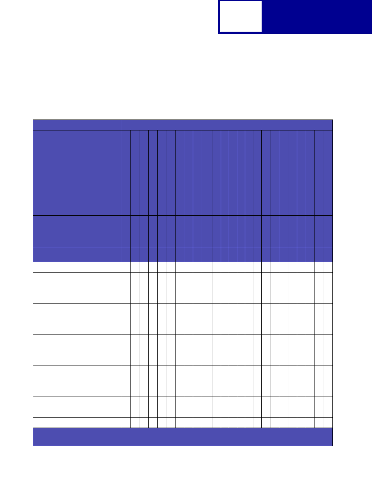
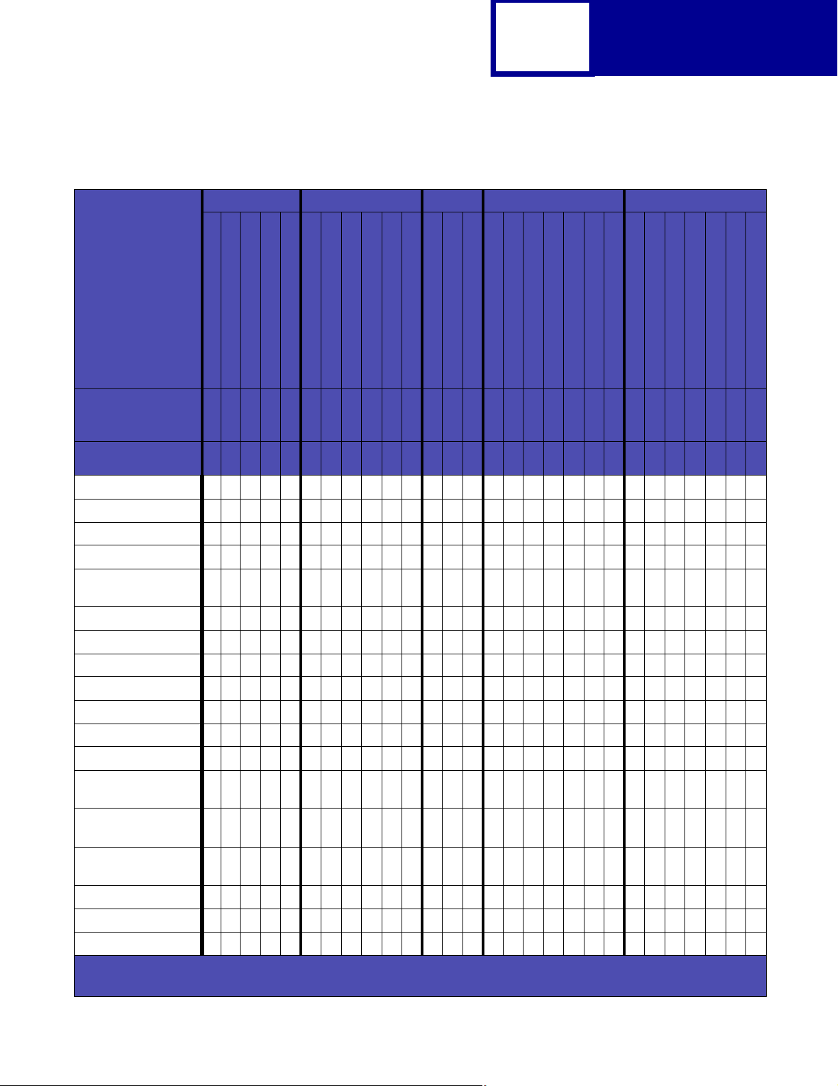
Table 2-6: E120, E120n, E238, E240, E240n, E250d, E250dn, E340, E342n, E350d, E352dn, and
E450dn PCL Emulation Symbol Sets - Latin 2, Latin 5, Latin 6, Cyrillic, Greek
Latin 2 Latin 5 Latin 6 Cyrillic Greek
Typeface / Symbol
Set
Windows 98 Latin 2
ISO 8859-2 Latin 2
PC-852 Latin 2
PC-8 Polish Mazovia
PC-8 PC Nova
Windows 98 Latin 5
ISO 8859-9 Latin 5
PC-857 Latin 5 (Turkish)
PC-853 Latin 3 (Turkish)
PC-Turkish (437T)
Turkish-8
Windows 98 Latin 6 (Baltic)
ISO 8859-10 Latin 6
PC-775 Baltic (PC-8 Latin 6)
Windows 98 Cyrillic
ISO 8859-5 Latin/Cyrillic
PC-866 Cyrillic
PC-855 Cyrillic
Russian-GOST
PC-8 Bulgarian
Ukrainian
Windows 98 Greek
ISO 8859-7 Latin/Greek
PC-869 Greece
PC-851 Greece
PC-8 Latin/Greek
PC-8 Greek Alternate (437G)
Greek-8
PJL Value
Symbol Set ID
Courier ✓✓✓✓✓✓✓✓✓✓✓✓✓✓✓✓✓✓✓✓✓✓✓✓✓✓✓✓
Courier Italic ✓✓✓✓✓✓✓✓✓✓✓✓✓✓✓✓✓✓✓✓✓✓✓✓✓✓✓✓
Courier Bold ✓✓✓✓✓✓✓✓✓✓✓✓✓✓✓✓✓✓✓✓✓✓✓✓✓✓✓✓
Courier Bold Italic ✓✓✓✓✓✓✓✓✓✓✓✓✓✓✓✓✓✓✓✓✓✓✓✓✓✓✓✓
CG Times ✓✓✓✓✓✓✓✓✓✓✓✓✓✓✓✓✓✓✓✓✓✓✓✓✓✓✓✓
CG Times Italic ✓✓✓✓✓✓✓✓✓✓✓✓✓✓✓✓✓✓✓✓✓✓✓✓✓✓✓✓
CG Times Bold ✓✓✓✓✓✓✓✓✓✓✓✓✓✓✓✓✓✓✓✓✓✓✓✓✓✓✓✓
CG Times Bold Italic ✓✓✓✓✓✓✓✓✓✓✓✓✓✓✓✓✓✓✓✓✓✓✓✓✓✓✓✓
Univers Medium ✓✓✓✓✓✓✓✓✓✓✓✓✓✓✓✓✓✓✓✓✓✓✓✓✓✓✓✓
Univers Medium Italic ✓✓✓✓✓✓✓✓✓✓✓✓✓✓✓✓✓✓✓✓✓✓✓✓✓✓✓✓
Univers Bold ✓✓✓✓✓✓✓✓✓✓✓✓✓✓✓✓✓✓✓✓✓✓✓✓✓✓✓✓
Univers Bold Italic ✓✓✓✓✓✓✓✓✓✓✓✓✓✓✓✓✓✓✓✓✓✓✓✓✓✓✓✓
Times New Roman ✓✓✓✘✓✓✓✓ ✘✓✓✓✓✓✘✘✘✘✘✘✘✘✘✘✘✘✘✘
Times New Roman
Italic
Times New Roman
Bold
Times New Roman
Bold Italic
Arial ✓✓✓✘✓✓✓✓✘✓✓✓✓✓ ✘✘✘✘✘✘✘✘✘✘✘✘✘✘
Arial Italic ✓✓✓✘✓✓✓✓✘✓✓✓✓✓✘✘✘✘✘✘✘✘✘✘✘✘✘✘
WINL2
ISOL2
PC852
9E2N17U
✓✓✓✘✓✓✓✓ ✘✓✓✓✓✓ ✘✘✘✘✘✘✘✘✘✘✘✘✘✘
✓✓✓✘✓✓✓✓ ✘✓✓✓✓✓ ✘✘✘✘✘✘✘✘✘✘✘✘✘✘
✓✓✓✘✓✓✓✓ ✘✓✓✓✓✓ ✘✘✘✘✘✘✘✘✘✘✘✘✘✘
WINL5
ISOL5
24Q
27Q
5T5N16U
18U
PC8TK
9T8T19L
6N
26U
9R
10N
3R
10R
12R
13R
14R
9G
12N
11G
10G
12G
14G
8G
Arial Bold ✓✓✓✘✓✓✓✓ ✘✓✓✓✓✓✘✘✘✘✘✘✘✘✘✘✘✘✘✘
✓ Indicates Typeface supports the specified Symbol Set.
✘ Indicates Typeface does not support the specified Symbol Set.
Page 33

2-21
PCL
Table 2-6: E120, E120n, E238, E240, E240n, E250d, E250dn, E340, E342n, E350d, E352dn, and
E450dn PCL Emulation Symbol Sets - Latin 2, Latin 5, Latin 6, Cyrillic, Greek (Continued)
Latin 2 Latin 5 Latin 6 Cyrillic Greek
Typeface / Symbol
Set
Windows 98 Latin 2
ISO 8859-2 Latin 2
PC-852 Latin 2
PC-8 Polish Mazovia
PC-8 PC Nova
Windows 98 Latin 5
ISO 8859-9 Latin 5
PC-857 Latin 5 (Turkish)
PC-853 Latin 3 (Turkish)
PC-Turkish (437T)
Turkish-8
Windows 98 Latin 6 (Baltic)
ISO 8859-10 Latin 6
PC-775 Baltic (PC-8 Latin 6)
Windows 98 Cyrillic
ISO 8859-5 Latin/Cyrillic
PC-866 Cyrillic
PC-855 Cyrillic
Russian-GOST
PC-8 Bulgarian
Ukrainian
Windows 98 Greek
ISO 8859-7 Latin/Greek
PC-869 Greece
PC-851 Greece
PC-8 Latin/Greek
PC-8 Greek Alternate (437G)
Greek-8
PJL Value
Symbol Set ID
Arial Bold Italic ✓✓✓✘✓✓✓✓✘ ✓✓✓✓✓✘✘✘✘✘✘✘✘✘✘✘✘✘✘
Letter Gothic ✓✓✓✘✓✓✓✓✘ ✓✓✓✓✓✘✘✘✘✘✘✘✘✘✘✘✘✘✘
Letter Gothic Italic ✓✓✓✘ ✓✓✓✓✘✓✓✓✓✓✘✘✘✘✘✘✘✘✘✘✘✘✘✘
Letter Gothic Bold ✓✓✓✘✓✓✓✓ ✘✓✓✓✓✓✘✘✘✘✘✘✘✘✘✘✘✘✘✘
Univers Condensed
Medium
Univers Condensed
Medium Italic
Univers Condensed
Bold
Univers Condensed
Bold Italic
Garamond Antiqua ✓✓✓✘ ✓✓✓✓✘✓✓✓✓✓✘✘✘✘✘✘✘✘✘✘✘✘✘✘
Garamond Kursiv ✓✓✓✘✓✓✓✓✘✓✓✓✓✓ ✘✘✘✘✘✘✘✘✘✘✘✘✘✘
Garamond Halbfett ✓✓✓ ✘✓✓✓✓✘✓✓✓✓✓✘✘✘✘✘✘✘✘✘✘✘✘✘✘
Garamond Kursiv
Halbfett
CG Omega ✓✓✓ ✘✓✓✓✓✘✓✓✓✓✓✘✘✘✘✘✘✘✘✘✘✘✘✘✘
CG Omega Italic ✓✓✓ ✘✓✓✓✓✘✓✓✓✓✓✘✘✘✘✘✘✘✘✘✘✘✘✘✘
WINL2
ISOL2
PC852
9E2N17U
✓✓✓✘✓✓✓✓ ✘✓✓✓✓✓ ✘✘✘✘✘✘✘✘✘✘✘✘✘✘
✓✓✓✘✓✓✓✓ ✘✓✓✓✓✓ ✘✘✘✘✘✘✘✘✘✘✘✘✘✘
✓✓✓✘✓✓✓✓ ✘✓✓✓✓✓ ✘✘✘✘✘✘✘✘✘✘✘✘✘✘
✓✓✓✘✓✓✓✓ ✘✓✓✓✓✓ ✘✘✘✘✘✘✘✘✘✘✘✘✘✘
✓✓✓✘✓✓✓✓ ✘✓✓✓✓✓ ✘✘✘✘✘✘✘✘✘✘✘✘✘✘
WINL5
ISOL5
24Q
27Q
5T5N16U
18U
PC8TK
9T8T19L
6N
26U
9R
10N
3R
10R
12R
13R
14R
9G
12N
11G
10G
12G
14G
8G
CG Omega Bold ✓✓✓✘ ✓✓✓✓✘✓✓✓✓✓✘✘✘✘✘✘✘✘✘✘✘✘✘✘
CG Omega Bold
Italic
Antique Olive ✓✓✓✘✓✓✓✓ ✘✓✓✓✓✓ ✘✘✘✘✘✘✘✘✘✘✘✘✘✘
✓ Indicates Typeface supports the specified Symbol Set.
✘ Indicates Typeface does not support the specified Symbol Set.
✓✓✓✘✓✓✓✓ ✘✓✓✓✓✓ ✘✘✘✘✘✘✘✘✘✘✘✘✘✘
Page 34
2-22
PCL
Table 2-6: E120, E120n, E238, E240, E240n, E250d, E250dn, E340, E342n, E350d, E352dn, and
E450dn PCL Emulation Symbol Sets - Latin 2, Latin 5, Latin 6, Cyrillic, Greek (Continued)
Latin 2 Latin 5 Latin 6 Cyrillic Greek
Typeface / Symbol
Set
Windows 98 Latin 2
ISO 8859-2 Latin 2
PC-852 Latin 2
PC-8 Polish Mazovia
PC-8 PC Nova
Windows 98 Latin 5
ISO 8859-9 Latin 5
PC-857 Latin 5 (Turkish)
PC-853 Latin 3 (Turkish)
PC-Turkish (437T)
Turkish-8
Windows 98 Latin 6 (Baltic)
ISO 8859-10 Latin 6
PC-775 Baltic (PC-8 Latin 6)
Windows 98 Cyrillic
ISO 8859-5 Latin/Cyrillic
PC-866 Cyrillic
PC-855 Cyrillic
Russian-GOST
PC-8 Bulgarian
Ukrainian
Windows 98 Greek
ISO 8859-7 Latin/Greek
PC-869 Greece
PC-851 Greece
PC-8 Latin/Greek
PC-8 Greek Alternate (437G)
Greek-8
PJL Value
Symbol Set ID
Antique Olive Italic ✓✓✓ ✘✓✓✓✓✘✓✓✓✓✓✘✘✘✘✘✘✘✘✘✘✘✘✘✘
Antique Olive Bold ✓✓✓✘✓✓✓✓ ✘✓✓✓✓✓ ✘✘✘✘✘✘✘✘✘✘✘✘✘✘
Albertus Medium ✓✓✓ ✘✓✓✓✓✘✓✓✓✓✓✘✘✘✘✘✘✘✘✘✘✘✘✘✘
Albertus Extra Bold ✓✓✓✘ ✓✓✓✓✘ ✓✓✓✓✓✘✘✘✘✘✘✘✘✘✘✘✘✘✘
Clarendon
Condensed Bold
Marigold ✓✓✓✘✓✓✓✓✘ ✓✓✓✓✓✘✘✘✘✘✘✘✘✘✘✘✘✘✘
Coronet ✓✓✓✘✓✓✓✓✘✓✓✓✓✓✘✘✘✘✘✘✘✘✘✘✘✘✘✘
Helvetica ✓✓✓✘ ✓✓✓✓✘ ✓✓✓✓✓✘✘✘✘✘✘✘✘✘✘✘✘✘✘
Helvetica Italic ✓✓✓✘✓✓✓✓✘ ✓✓✓✓✓✘✘✘✘✘✘✘✘✘✘✘✘✘✘
Helvetica Bold ✓✓✓✘✓✓✓✓✘ ✓✓✓✓✓✘✘✘✘✘✘✘✘✘✘✘✘✘✘
Helvetica Bold Italic ✓✓✓✘✓✓✓✓ ✘✓✓✓✓✓✘✘✘✘✘✘✘✘✘✘✘✘✘✘
Helvetica Narrow ✓✓✓ ✘✓✓✓✓✘✓✓✓✓✓✘✘✘✘✘✘✘✘✘✘✘✘✘✘
Helvetica Narrow
Italic
Helvetica Narrow
Bold
Helvetica Narrow
Bold Italic
WINL2
ISOL2
PC852
9E2N17U
✓✓✓✘✓✓✓✓ ✘✓✓✓✓✓ ✘✘✘✘✘✘✘✘✘✘✘✘✘✘
✓✓✓✘✓✓✓✓ ✘✓✓✓✓✓ ✘✘✘✘✘✘✘✘✘✘✘✘✘✘
✓✓✓✘✓✓✓✓ ✘✓✓✓✓✓ ✘✘✘✘✘✘✘✘✘✘✘✘✘✘
✓✓✓✘✓✓✓✓ ✘✓✓✓✓✓ ✘✘✘✘✘✘✘✘✘✘✘✘✘✘
WINL5
ISOL5
24Q
27Q
5T5N16U
18U
PC8TK
9T8T19L
6N
26U
9R
10N
3R
10R
12R
13R
14R
9G
12N
11G
10G
12G
14G
8G
Palatino Roman ✓✓✓✘✓✓✓✓ ✘✓✓✓✓✓ ✘✘✘✘✘✘✘✘✘✘✘✘✘✘
Palatino Italic ✓✓✓✘✓✓✓✓ ✘✓✓✓✓✓✘✘✘✘✘✘✘✘✘✘✘✘✘✘
Palatino Bold ✓✓✓✘✓✓✓✓✘ ✓✓✓✓✓✘✘✘✘✘✘✘✘✘✘✘✘✘✘
✓ Indicates Typeface supports the specified Symbol Set.
✘ Indicates Typeface does not support the specified Symbol Set.
Page 35

2-23
PCL
Table 2-6: E120, E120n, E238, E240, E240n, E250d, E250dn, E340, E342n, E350d, E352dn, and
E450dn PCL Emulation Symbol Sets - Latin 2, Latin 5, Latin 6, Cyrillic, Greek (Continued)
Latin 2 Latin 5 Latin 6 Cyrillic Greek
Typeface / Symbol
Set
Windows 98 Latin 2
ISO 8859-2 Latin 2
PC-852 Latin 2
PC-8 Polish Mazovia
PC-8 PC Nova
Windows 98 Latin 5
ISO 8859-9 Latin 5
PC-857 Latin 5 (Turkish)
PC-853 Latin 3 (Turkish)
PC-Turkish (437T)
Turkish-8
Windows 98 Latin 6 (Baltic)
ISO 8859-10 Latin 6
PC-775 Baltic (PC-8 Latin 6)
Windows 98 Cyrillic
ISO 8859-5 Latin/Cyrillic
PC-866 Cyrillic
PC-855 Cyrillic
Russian-GOST
PC-8 Bulgarian
Ukrainian
Windows 98 Greek
ISO 8859-7 Latin/Greek
PC-869 Greece
PC-851 Greece
PC-8 Latin/Greek
PC-8 Greek Alternate (437G)
Greek-8
PJL Value
Symbol Set ID
Palatino Bold Italic ✓✓✓✘✓✓✓✓✘✓✓✓✓✓ ✘✘✘✘✘✘✘✘✘✘✘✘✘✘
ITC Bookman Light ✓✓✓ ✘✓✓✓✓✘✓✓✓✓✓✘✘✘✘✘✘✘✘✘✘✘✘✘✘
ITC Bookman Light
Italic
ITC Bookman Demi ✓✓✓ ✘✓✓✓✓ ✘✓✓✓✓✓✘✘✘✘✘✘✘✘✘✘✘✘✘✘
ITC Bookman Demi
Italic
ITC Avant Garde
Book
ITC Avant Garde
Book Oblique
ITC Avant Garde
Demi
ITC Avant Garde
Demi Oblique
Century Schoolbook
Roman
Century Schoolbook
Italic
WINL2
ISOL2
PC852
9E2N17U
✓✓✓✘✓✓✓✓ ✘✓✓✓✓✓ ✘✘✘✘✘✘✘✘✘✘✘✘✘✘
✓✓✓✘✓✓✓✓ ✘✓✓✓✓✓ ✘✘✘✘✘✘✘✘✘✘✘✘✘✘
✓✓✓✘✓✓✓✓ ✘✓✓✓✓✓ ✘✘✘✘✘✘✘✘✘✘✘✘✘✘
✓✓✓✘✓✓✓✓ ✘✓✓✓✓✓ ✘✘✘✘✘✘✘✘✘✘✘✘✘✘
✓✓✓✘✓✓✓✓ ✘✓✓✓✓✓ ✘✘✘✘✘✘✘✘✘✘✘✘✘✘
✓✓✓✘✓✓✓✓ ✘✓✓✓✓✓ ✘✘✘✘✘✘✘✘✘✘✘✘✘✘
✓✓✓✘✓✓✓✓ ✘✓✓✓✓✓ ✘✘✘✘✘✘✘✘✘✘✘✘✘✘
✓✓✓✘✓✓✓✓ ✘✓✓✓✓✓ ✘✘✘✘✘✘✘✘✘✘✘✘✘✘
WINL5
ISOL5
24Q
27Q
5T5N16U
18U
PC8TK
9T8T19L
6N
26U
9R
10N
3R
10R
12R
13R
14R
9G
12N
11G
10G
12G
14G
8G
Century Schoolbook
Bold
Century Schoolbook
Bold Italic
ITC Zapf Chancery
Medium Italic
✓ Indicates Typeface supports the specified Symbol Set.
✘ Indicates Typeface does not support the specified Symbol Set.
✓✓✓✘✓✓✓✓ ✘✓✓✓✓✓ ✘✘✘✘✘✘✘✘✘✘✘✘✘✘
✓✓✓✘✓✓✓✓ ✘✓✓✓✓✓ ✘✘✘✘✘✘✘✘✘✘✘✘✘✘
✓✓✓✘✓✓✓✓ ✘✓✓✓✓✓ ✘✘✘✘✘✘✘✘✘✘✘✘✘✘
Page 36

2-24
PCL
Table 2-6: E120, E120n, E238, E240, E240n, E250d, E250dn, E340, E342n, E350d, E352dn, and
E450dn PCL Emulation Symbol Sets - Latin 2, Latin 5, Latin 6, Cyrillic, Greek (Continued)
Latin 2 Latin 5 Latin 6 Cyrillic Greek
Typeface / Symbol
Set
Windows 98 Latin 2
ISO 8859-2 Latin 2
PC-852 Latin 2
PC-8 Polish Mazovia
PC-8 PC Nova
Windows 98 Latin 5
ISO 8859-9 Latin 5
PC-857 Latin 5 (Turkish)
PC-853 Latin 3 (Turkish)
PC-Turkish (437T)
Turkish-8
Windows 98 Latin 6 (Baltic)
ISO 8859-10 Latin 6
PC-775 Baltic (PC-8 Latin 6)
Windows 98 Cyrillic
ISO 8859-5 Latin/Cyrillic
PC-866 Cyrillic
PC-855 Cyrillic
Russian-GOST
PC-8 Bulgarian
Ukrainian
Windows 98 Greek
ISO 8859-7 Latin/Greek
PC-869 Greece
PC-851 Greece
PC-8 Latin/Greek
PC-8 Greek Alternate (437G)
Greek-8
PJL Value
Symbol Set ID
CourierPS ✓✓✓✘✓✓✓✓ ✘✓✓✓✓✓ ✘✘✘✘✘✘✘✘✘✘✘✘✘✘
CourierPS Oblique ✓✓✓✘✓✓✓✓ ✘✓✓✓✓✓ ✘✘✘✘✘✘✘✘✘✘✘✘✘✘
CourierPS Bold ✓✓✓✘ ✓✓✓✓✘ ✓✓✓✓✓✘✘✘✘✘✘✘✘✘✘✘✘✘✘
CourierPS Bold
Oblique
Times Roman ✓✓✓✘✓✓✓✓✘ ✓✓✓✓✓✘✘✘✘✘✘✘✘✘✘✘✘✘✘
Times Italic ✓✓✓✘✓✓✓✓ ✘✓✓✓✓✓✘✘✘✘✘✘✘✘✘✘✘✘✘✘
Times Bold ✓✓✓✘✓✓✓✓✘ ✓✓✓✓✓✘✘✘✘✘✘✘✘✘✘✘✘✘✘
Times Bold Italic ✓✓✓✘ ✓✓✓✓✘✓✓✓✓✓✘✘✘✘✘✘✘✘✘✘✘✘✘✘
Helvetica Light ✘✘✘✘✘✘✘✘✘✘✘✘✘✘✘✘✘✘✘✘✘✘✘✘✘✘✘✘
Helvetica Light
Oblique
Helvetica Black ✘✘✘✘✘✘✘✘✘✘✘✘✘✘✘✘✘✘✘✘✘✘✘✘✘✘✘✘
Helvetica Black
Oblique
Line Printer 16 ✓✓✓✓✓✓✓✓✓✓✓✓✓✓✓✓✓✓✓✓✓✓✓✓✓✓✓✓
WINL2
ISOL2
PC852
9E2N17U
✓✓✓✘✓✓✓✓ ✘✓✓✓✓✓ ✘✘✘✘✘✘✘✘✘✘✘✘✘✘
✘✘✘✘✘✘✘✘✘✘✘✘✘✘✘✘✘✘✘✘✘✘✘✘✘✘✘✘
✘✘✘✘✘✘✘✘✘✘✘✘✘✘✘✘✘✘✘✘✘✘✘✘✘✘✘✘
WINL5
ISOL5
24Q
27Q
5T5N16U
18U
PC8TK
9T8T19L
6N
26U
9R
10N
3R
10R
12R
13R
14R
9G
12N
11G
10G
12G
14G
8G
POSTNET Barcode ✘✘✘✘✘✘✘✘✘✘✘✘✘✘✘✘✘✘✘✘✘✘✘✘✘✘✘✘
C39 Narrow ✘✘✘✘✘✘✘✘✘✘✘✘✘✘✘✘✘✘✘✘✘✘✘✘✘✘✘✘
C39 Regular ✘✘✘✘✘✘✘✘✘✘✘✘✘✘✘✘✘✘✘✘✘✘✘✘✘✘✘✘
C39 Wide ✘✘✘✘✘✘✘✘✘✘✘✘✘✘✘✘✘✘✘✘✘✘✘✘✘✘✘✘
OCR-A ✘✘✘✘✘✘✘✘✘✘✘✘✘✘✘✘✘✘✘✘✘✘✘✘✘✘✘✘
OCR-B ✓✓✓✓✓✘✘✘✘✘✘✘✘✘✘✘✘✘✘✘✘✘✘✘✘✘✘✘
✓ Indicates Typeface supports the specified Symbol Set.
✘ Indicates Typeface does not support the specified Symbol Set.
Page 37
2-25
PCL
Table 2-6: E120, E120n, E238, E240, E240n, E250d, E250dn, E340, E342n, E350d, E352dn, and
E450dn PCL Emulation Symbol Sets - Latin 2, Latin 5, Latin 6, Cyrillic, Greek (Continued)
Latin 2 Latin 5 Latin 6 Cyrillic Greek
Typeface / Symbol
Set
Windows 98 Latin 2
ISO 8859-2 Latin 2
PC-852 Latin 2
PC-8 Polish Mazovia
PC-8 PC Nova
Windows 98 Latin 5
ISO 8859-9 Latin 5
PC-857 Latin 5 (Turkish)
PC-853 Latin 3 (Turkish)
PC-Turkish (437T)
Turkish-8
Windows 98 Latin 6 (Baltic)
ISO 8859-10 Latin 6
PC-775 Baltic (PC-8 Latin 6)
Windows 98 Cyrillic
ISO 8859-5 Latin/Cyrillic
PC-866 Cyrillic
PC-855 Cyrillic
Russian-GOST
PC-8 Bulgarian
Ukrainian
Windows 98 Greek
ISO 8859-7 Latin/Greek
PC-869 Greece
PC-851 Greece
PC-8 Latin/Greek
PC-8 Greek Alternate (437G)
Greek-8
PJL Value
Symbol Set ID
Wingdings ✘✘✘✘✘✘✘✘✘✘✘✘✘✘✘✘✘✘✘✘✘✘✘✘✘✘✘✘
Symbol ✘✘✘✘✘✘✘✘✘✘✘✘✘✘✘✘✘✘✘✘✘✘✘✘✘✘✘✘
SymbolPS ✘✘✘✘✘✘✘✘✘✘✘✘✘✘✘✘✘✘✘✘✘✘✘✘✘✘✘✘
ITC Zapf Dingbats ✘✘✘✘✘✘✘✘✘✘✘✘✘✘✘✘✘✘✘✘✘✘✘✘✘✘✘✘
✓ Indicates Typeface supports the specified Symbol Set.
✘ Indicates Typeface does not support the specified Symbol Set.
WINL2
ISOL2
9E2N17U
PC852
24Q
27Q
WINL5
ISOL5
5T5N16U
18U
PC8TK
9T8T19L
6N
26U
9R
10N
3R
10R
12R
13R
14R
9G
12N
11G
10G
12G
14G
8G
Page 38

2-26
PCL
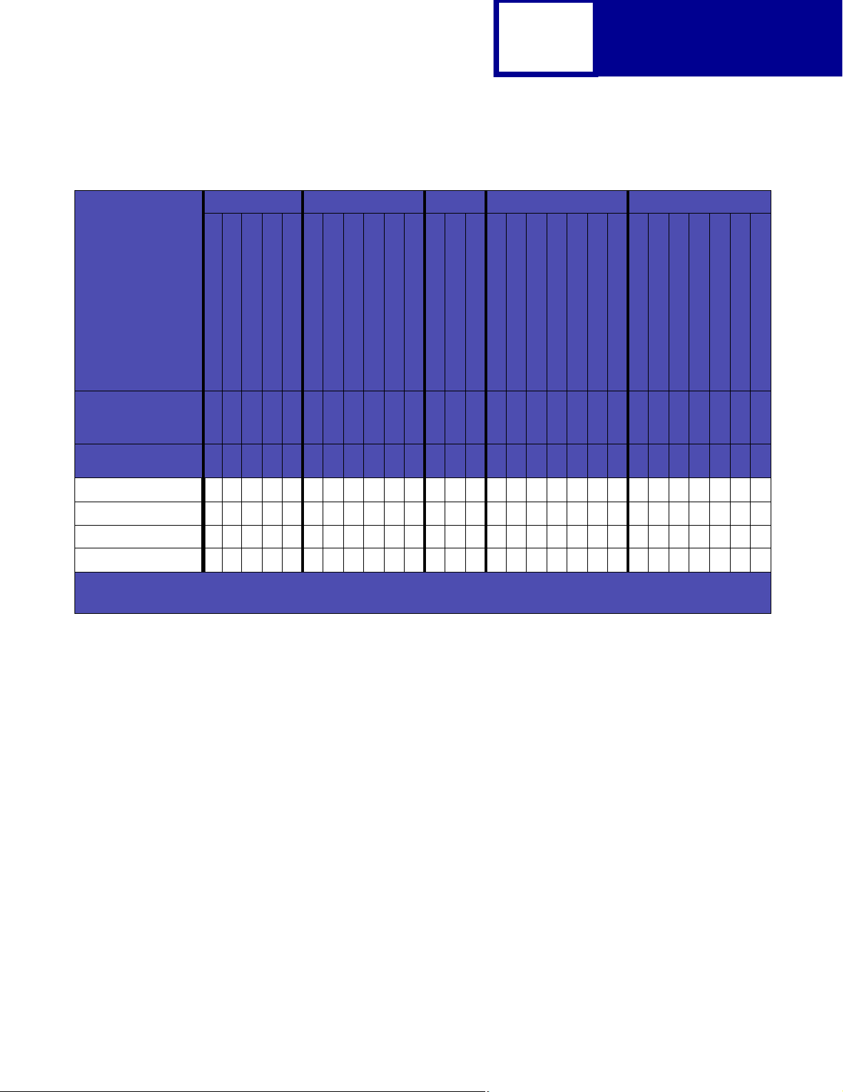
Table 2-7: Lexmark E120, E120n, E238, E240, E240n, E250d, E250dn, E340, E342n, E350d,
E352dn, and E450dn PCL Emulation Symbol Sets - Specials
Specials
Typeface / Symbol Set
PJL Value
Symbol Set ID
Courier ✓✓✓✓✓ ✘✘✘✘ ✘ ✘ ✘ ✘✘✘✘✘
Courier Italic ✓✓✓✓✓✘✘✘✘ ✘ ✘ ✘ ✘✘✘✘✘
Courier Bold ✓✓✓✓✓ ✘✘✘✘ ✘ ✘ ✘ ✘✘✘✘✘
Courier Bold Italic ✓✓✓✓✓✘✘✘✘ ✘ ✘ ✘ ✘✘✘✘✘
CG Times ✓✓✓✓✓✘✘✘✘ ✘ ✘ ✘ ✘✘✘✘✘
CG Times Italic ✓✓✓✓✓ ✘✘✘✘ ✘ ✘ ✘ ✘✘✘✘✘
CG Times Bold ✓✓✓✓✓✘✘✘✘ ✘ ✘ ✘ ✘✘✘✘✘
CG Times Bold Italic ✓✓✓✓✓✘✘✘✘ ✘ ✘ ✘ ✘✘✘✘✘
Univers Medium ✓✓✓✓✓✘✘✘✘ ✘ ✘ ✘ ✘✘✘✘✘
Univers Medium Italic ✓✓✓✓✓✘✘✘✘ ✘ ✘ ✘ ✘✘✘✘✘
Univers Bold ✓✓✓✓✓✘✘✘✘ ✘ ✘ ✘ ✘✘✘✘✘
Univers Bold Italic ✓✓✓✓✓✘✘✘✘ ✘ ✘ ✘ ✘✘✘✘✘
Times New Roman ✓✓✓✓✓✘✘✘✘ ✘ ✘ ✘ ✘✘✘✘✘
Times New Roman Italic ✓✓✓✓✓✘✘✘✘ ✘ ✘ ✘ ✘✘✘✘✘
Ventura Math
VNMATH
6M
PS Math
Math-8
PSMATH
MATH8
5M
8M
Pi font
Microsoft Publishing
PC-911 Katakana
PIFONT
MSPUBL
15U6J3K
POSTNET Barcode
15Y
OCR-A
0O
OCR-B
1O
C39 Bar Code
(Upper Case)
C39 Bar Code
(plus Lower Case)
C39 Bar Code
9Y
109Y
(plus Human Readable)
209Y
Symbol
Wingdings
19M
579L
Ventura ITC Zapf Dingbats
9L
PS ITC Zapf Dingbats
10L
PCL ITC Zapf Dingbats
14L
Times New Roman Bold ✓✓✓✓✓✘✘✘✘ ✘ ✘ ✘ ✘✘✘✘✘
Times New Roman BoldItalic ✓✓✓✓✓✘✘✘✘ ✘ ✘ ✘ ✘✘✘✘✘
Arial ✓✓✓✓✓✘✘✘✘ ✘ ✘ ✘ ✘✘✘✘✘
Arial Italic ✓✓✓✓✓✘✘✘✘ ✘ ✘ ✘ ✘✘✘✘✘
Arial Bold ✓✓✓✓✓✘✘✘✘ ✘ ✘ ✘ ✘✘✘✘✘
Arial Bold Italic ✓✓✓✓✓✘✘✘✘ ✘ ✘ ✘ ✘✘✘✘✘
Letter Gothic ✓✓✓✓✓✘✘✘✘ ✘ ✘ ✘ ✘✘✘✘✘
✓ Indicates Typeface supports the specified Symbol Set.
✘ Indicates Typeface does not support the specified Symbol Set.
Page 39

2-27
PCL
Table 2-7: Lexmark E120, E120n, E238, E240, E240n, E250d, E250dn, E340, E342n, E350d,
E352dn, and E450dn PCL Emulation Symbol Sets - Specials (Continued)
Specials
Typeface / Symbol Set
PJL Value
Symbol Set ID
Letter Gothic Italic ✓✓✓✓✓ ✘✘✘✘ ✘ ✘ ✘ ✘✘✘✘✘
Letter Gothic Bold ✓✓✓✓✓✘✘✘✘ ✘ ✘ ✘ ✘✘✘✘✘
Univers Condensed Medium ✓✓✓✓✓✘✘✘✘ ✘ ✘ ✘ ✘✘✘✘✘
Univers Condensed Medium Italic ✓✓✓✓✓✘✘✘✘ ✘ ✘ ✘ ✘✘✘✘✘
Univers Condensed Bold ✓✓✓✓✓ ✘✘✘✘ ✘ ✘ ✘ ✘✘✘✘✘
Univers Condensed Bold Italic ✓✓✓✓✓✘✘✘✘ ✘ ✘ ✘ ✘✘✘✘✘
Garamond Antiqua ✓✓✓✓✓✘✘✘✘ ✘ ✘ ✘ ✘✘✘✘✘
Garamond Kursiv ✓✓✓✓✓✘✘✘✘ ✘ ✘ ✘ ✘✘✘✘✘
Garamond Halbfett ✓✓✓✓✓✘✘✘✘ ✘ ✘ ✘ ✘✘✘✘✘
Garamond Kursiv Halbfett ✓✓✓✓✓✘✘✘✘ ✘ ✘ ✘ ✘✘✘✘✘
CG Omega ✓✓✓✓✓✘✘✘✘ ✘ ✘ ✘ ✘✘✘✘✘
CG Omega Italic ✓✓✓✓✓✘✘✘✘ ✘ ✘ ✘ ✘✘✘✘✘
CG Omega Bold ✓✓✓✓✓ ✘✘✘✘ ✘ ✘ ✘ ✘✘✘✘✘
CG Omega Bold Italic ✓✓✓✓✓ ✘✘✘✘ ✘ ✘ ✘ ✘✘✘✘✘
Ventura Math
VNMATH
6M
PS Math
Math-8
PSMATH
MATH8
5M
8M
Pi font
Microsoft Publishing
PC-911 Katakana
PIFONT
MSPUBL
15U6J3K
POSTNET Barcode
15Y
OCR-A
0O
OCR-B
1O
C39 Bar Code
(Upper Case)
C39 Bar Code
(plus Lower Case)
C39 Bar Code
9Y
109Y
(plus Human Readable)
209Y
Symbol
Wingdings
19M
579L
Ventura ITC Zapf Dingbats
9L
PS ITC Zapf Dingbats
10L
PCL ITC Zapf Dingbats
14L
Antique Olive ✓✓✓✓✓✘✘✘✘ ✘ ✘ ✘ ✘✘✘✘✘
Antique Olive Italic ✓✓✓✓✓✘✘✘✘ ✘ ✘ ✘ ✘✘✘✘✘
Antique Olive Bold ✓✓✓✓✓✘✘✘✘ ✘ ✘ ✘ ✘✘✘✘✘
Albertus Medium ✓✓✓✓✓✘✘✘✘ ✘ ✘ ✘ ✘✘✘✘✘
Albertus Extra Bold ✓✓✓✓✓✘✘✘✘ ✘ ✘ ✘ ✘✘✘✘✘
Clarendon Condensed Bold ✓✓✓✓✓✘✘✘✘ ✘ ✘ ✘ ✘✘✘✘✘
Marigold ✓✓✓✓✓✘✘✘✘ ✘ ✘ ✘ ✘✘✘✘✘
✓ Indicates Typeface supports the specified Symbol Set.
✘ Indicates Typeface does not support the specified Symbol Set.
Page 40

2-28
PCL
Table 2-7: Lexmark E120, E120n, E238, E240, E240n, E250d, E250dn, E340, E342n, E350d,
E352dn, and E450dn PCL Emulation Symbol Sets - Specials (Continued)
Specials
Typeface / Symbol Set
PJL Value
Symbol Set ID
Coronet ✓✓✓✓✓✘✘✘✘ ✘ ✘ ✘ ✘✘✘✘✘
Helvetica ✓✓✓✓✓✘✘✘✘ ✘ ✘ ✘ ✘✘✘✘✘
Helvetica Italic ✓✓✓✓✓✘✘✘✘ ✘ ✘ ✘ ✘✘✘✘✘
Helvetica Bold ✓✓✓✓✓✘✘✘✘ ✘ ✘ ✘ ✘✘✘✘✘
Helvetica Bold Italic ✓✓✓✓✓✘✘✘✘ ✘ ✘ ✘ ✘✘✘✘✘
Helvetica Narrow ✓✓✓✓✓ ✘✘✘✘ ✘ ✘ ✘ ✘✘✘✘✘
Helvetica Narrow Italic ✓✓✓✓✓✘✘✘✘ ✘ ✘ ✘ ✘✘✘✘✘
Helvetica Narrow Bold ✓✓✓✓✓✘✘✘✘ ✘ ✘ ✘ ✘✘✘✘✘
Helvetica Narrow Bold Italic ✓✓✓✓✓✘✘✘✘ ✘ ✘ ✘ ✘✘✘✘✘
Palatino Roman ✓✓✓✓✓✘✘✘✘ ✘ ✘ ✘ ✘✘✘✘✘
Palatino Italic ✓✓✓✓✓✘✘✘✘ ✘ ✘ ✘ ✘✘✘✘✘
Palatino Bold ✓✓✓✓✓ ✘✘✘✘ ✘ ✘ ✘ ✘✘✘✘✘
Palatino Bold Italic ✓✓✓✓✓✘✘✘✘ ✘ ✘ ✘ ✘✘✘✘✘
ITC Bookman Light ✓✓✓✓✓✘✘✘✘ ✘ ✘ ✘ ✘✘✘✘✘
Ventura Math
VNMATH
6M
PS Math
Math-8
PSMATH
MATH8
5M
8M
Pi font
Microsoft Publishing
PC-911 Katakana
PIFONT
MSPUBL
15U6J3K
POSTNET Barcode
15Y
OCR-A
0O
OCR-B
1O
C39 Bar Code
(Upper Case)
C39 Bar Code
(plus Lower Case)
C39 Bar Code
9Y
109Y
(plus Human Readable)
209Y
Symbol
Wingdings
19M
579L
Ventura ITC Zapf Dingbats
9L
PS ITC Zapf Dingbats
10L
PCL ITC Zapf Dingbats
14L
ITC Bookman Light Italic ✓✓✓✓✓✘✘✘✘ ✘ ✘ ✘ ✘✘✘✘✘
ITC Bookman Demi ✓✓✓✓✓✘✘✘✘ ✘ ✘ ✘ ✘✘✘✘✘
ITC Bookman Demi Italic ✓✓✓✓✓✘✘✘✘ ✘ ✘ ✘ ✘✘✘✘✘
ITC Avant Garde Book ✓✓✓✓✓ ✘✘✘✘ ✘ ✘ ✘ ✘✘✘✘✘
ITC Avant Garde Book Oblique ✓✓✓✓✓✘✘✘✘ ✘ ✘ ✘ ✘✘✘✘✘
ITC Avant Garde Demi ✓✓✓✓✓✘✘✘✘ ✘ ✘ ✘ ✘✘✘✘✘
ITC Avant Garde Demi Oblique ✓✓✓✓✓✘✘✘✘ ✘ ✘ ✘ ✘✘✘✘✘
✓ Indicates Typeface supports the specified Symbol Set.
✘ Indicates Typeface does not support the specified Symbol Set.
Page 41

2-29
PCL
Table 2-7: Lexmark E120, E120n, E238, E240, E240n, E250d, E250dn, E340, E342n, E350d,
E352dn, and E450dn PCL Emulation Symbol Sets - Specials (Continued)
Specials
Typeface / Symbol Set
PJL Value
Symbol Set ID
Century Schoolbook Roman ✓✓✓✓✓✘✘✘✘ ✘ ✘ ✘ ✘✘✘✘✘
Century Schoolbook Italic ✓✓✓✓✓✘✘✘✘ ✘ ✘ ✘ ✘✘✘✘✘
Century Schoolbook Bold ✓✓✓✓✓✘✘✘✘ ✘ ✘ ✘ ✘✘✘✘✘
Century Schoolbook Bold Italic ✓✓✓✓✓✘✘✘✘ ✘ ✘ ✘ ✘✘✘✘✘
ITC Zapf Chancery Medium Italic ✓✓✓✓✓✘✘✘✘ ✘ ✘ ✘ ✘✘✘✘✘
CourierPS ✓✓✓✓✓✘✘✘✘ ✘ ✘ ✘ ✘✘✘✘✘
CourierPS Oblique ✓✓✓✓✓✘✘✘✘ ✘ ✘ ✘ ✘✘✘✘✘
CourierPS Bold ✓✓✓✓✓✘✘✘✘ ✘ ✘ ✘ ✘✘✘✘✘
CourierPS Bold Oblique ✓✓✓✓✓✘✘✘✘ ✘ ✘ ✘ ✘✘✘✘✘
Times Roman ✓✓✓✓✓✘✘✘✘ ✘ ✘ ✘ ✘✘✘✘✘
Times Italic ✓✓✓✓✓✘✘✘✘ ✘ ✘ ✘ ✘✘✘✘✘
Times Bold ✓✓✓✓✓✘✘✘✘ ✘ ✘ ✘ ✘✘✘✘✘
Times Bold Italic ✓✓✓✓✓✘✘✘✘ ✘ ✘ ✘ ✘✘✘✘✘
Helvetica Light ✘✘✘✘✘✘✘✘✘ ✘ ✘ ✘ ✘✘✘✘✘
Ventura Math
VNMATH
6M
PS Math
Math-8
PSMATH
MATH8
5M
8M
Pi font
Microsoft Publishing
PC-911 Katakana
PIFONT
MSPUBL
15U6J3K
POSTNET Barcode
15Y
OCR-A
0O
OCR-B
1O
C39 Bar Code
(Upper Case)
C39 Bar Code
(plus Lower Case)
C39 Bar Code
9Y
109Y
(plus Human Readable)
209Y
Symbol
Wingdings
19M
579L
Ventura ITC Zapf Dingbats
9L
PS ITC Zapf Dingbats
10L
PCL ITC Zapf Dingbats
14L
Helvetica Light Oblique ✘✘✘✘✘✘✘✘✘ ✘ ✘ ✘ ✘✘✘✘✘
Helvetica Black ✘✘✘✘✘✘✘✘✘ ✘ ✘ ✘ ✘✘✘✘✘
Helvetica Black Oblique ✘✘✘✘✘✘✘✘✘ ✘ ✘ ✘ ✘✘✘✘✘
Line Printer 16 ✓✓✓✓✓✓✘ ✘ ✘ ✘ ✘ ✘ ✘✘✘✘✘
POSTNET Barcode ✘✘✘✘✘✘✓✘✘ ✘ ✘ ✘ ✘✘✘✘✘
C39 Narrow ✘✘✘✘✘✘✘✘✘ ✓ ✓ ✓ ✘✘✘✘✘
C39 Regular ✘✘✘✘✘✘✘✘✘ ✓ ✓ ✓ ✘✘✘✘✘
✓ Indicates Typeface supports the specified Symbol Set.
✘ Indicates Typeface does not support the specified Symbol Set.
Page 42

2-30
PCL
Table 2-7: Lexmark E120, E120n, E238, E240, E240n, E250d, E250dn, E340, E342n, E350d,
E352dn, and E450dn PCL Emulation Symbol Sets - Specials (Continued)
Specials
Typeface / Symbol Set
PJL Value
Symbol Set ID
C39 Wide ✘✘✘✘✘✘✘✘✘ ✓ ✓ ✓ ✘✘✘✘✘
OCR-A ✘✘✘✘✘✘✘✓✘ ✘ ✘ ✘ ✘✘✘✘✘
OCR-B ✘✘✘✘✘✘✘✘✓ ✘ ✘ ✘ ✘✘✘✘✘
Wingdings ✘✘✘✘✘✘✘✘✘ ✘ ✘ ✘ ✘✓✘✘✘
Symbol ✘✘✘✘✘✘✘✘✘ ✘ ✘ ✘ ✓✘✘✘✘
SymbolPS ✘✘✘✘✘✘✘✘✘ ✘ ✘ ✘ ✓✘✘✘✘
ITC Zapf Dingbats ✘✘✘✘✘✘✘✘✘ ✘ ✘ ✘ ✘✘✓✓✓
✓ Indicates Typeface supports the specified Symbol Set.
✘ Indicates Typeface does not support the specified Symbol Set.
Ventura Math
VNMATH
6M
PS Math
Math-8
PSMATH
MATH8
5M
8M
Pi font
Microsoft Publishing
PC-911 Katakana
PIFONT
MSPUBL
15U6J3K
POSTNET Barcode
15Y
OCR-A
0O
OCR-B
1O
C39 Bar Code
(Upper Case)
C39 Bar Code
(plus Lower Case)
C39 Bar Code
9Y
109Y
(plus Human Readable)
209Y
Symbol
Wingdings
19M
579L
Ventura ITC Zapf Dingbats
9L
PS ITC Zapf Dingbats
10L
PCL ITC Zapf Dingbats
14L
Table 2-8: Lexmark E120, E120n, E238, E240, E240n, E250d, E250dn, E340,
E342n, E350d, E352dn, and E450dn ISO PCL Emulation Symbol Sets
Symbol Set ID Symbol Set / Typeface
1E ISO 4: United Kingdom
0U ISO 6: ASCII
0S ISO 11: Swedish for Names
0I ISO 15: Italian
2S ISO 17: Spanish
1G ISO 21: German
0D ISO 60: Norwegian Version 1
1F ISO 69: French
Page 43

2-31
PCL
Table 2-8: Lexmark E120, E120n, E238, E240, E240n, E250d, E250dn, E340,
E342n, E350d, E352dn, and E450dn ISO PCL Emulation Symbol
Symbol Set ID Symbol Set / Typeface
2U ISO 2: IRV (International Ref Version)
0F ISO 25: French
0G ISO: HP German
0K ISO 14: JIS ASCII
2K ISO 57: Chinese
3S ISO 10: Swedish
1S ISO: HP Spanish
6S ISO 85: Spanish
4S ISO 16: Portuguese
5S ISO 84: Portuguese
1D ISO 61: Norwegian Version 2
Table 2-9: Lexmark E120, E120n, E238, E240, E240n, E250d, E250dn, E340, E342n, E350d,
E352dn, and E450dn PCL Emulation Symbol Sets - Latin 1
Latin 1
Typeface / Symbol Set
PJL Value
Legal
Windows 3.0 Latin 1
Windows 98 Latin 1
ISO 8859-1 Latin 1 (ECMA-94)
ISO 8859-15 Latin 9
PC-8, Code Page 437
PC-8 Danish/Norwegian (437N)
PC-850 Multilingual
PC-858 Multilingual Euro
PC-860 Portugal
PC-861 Iceland
PC-863 Canadian French
PC-865 Nordic
PC-1004 OS/2
ABICOMP Brazil/Portugal
ABICOMP International
Roman-8
Roman-9
Roman Extension
PS Text
MC Text
Desk Top
LEGAL
WIN30
WINL1
ISOL1
ISOL9
PC8
PC8DN
PC850
PC858
ROMAN8
PSTEXT
DESKTOP
Ventura International
Ventura US
VNINTL
VNUS
Symbol Set ID
Courier ✓✓✓✓✓✓✓✓✓ ✓ ✓✓✓✓✓✓✓ ✓ ✓✓✓✓✓✓
Courier Italic ✓✓✓✓✓✓✓✓✓ ✓ ✓✓✓✓✓✓✓ ✓ ✓✓✓✓✓✓
Courier Bold ✓✓✓✓✓✓✓✓✓ ✓ ✓✓✓✓✓✓✓ ✓ ✓✓✓✓✓✓
✓ Indicates Typeface supports the specified Symbol Set.
✘ Indicates Typeface does not support the specified Symbol Set.
1U9U19U
0N9N10U
11U
12U
13U
20U
21U
23U
25U
9J
13P
14P
8U4U0E
10J
12J
7J
13J
14J
Page 44

2-32
PCL
Table 2-9: Lexmark E120, E120n, E238, E240, E240n, E250d, E250dn, E340, E342n, E350d,
E352dn, and E450dn PCL Emulation Symbol Sets - Latin 1 (Continued)
Latin 1
Typeface / Symbol Set
PJL Value
Symbol Set ID
Courier Bold Italic ✓✓✓✓✓✓✓✓✓ ✓ ✓✓✓✓✓✓✓ ✓ ✓✓✓✓✓✓
CG Times ✓✓✓✓✓✓✓✓✓ ✓ ✓✓✓✓✓✓✓ ✓ ✓✓✓✓✓✓
CG Times Italic ✓✓✓✓✓✓✓✓✓ ✓ ✓✓✓✓✓✓✓ ✓ ✓✓✓✓✓✓
CG Times Bold ✓✓✓✓✓✓✓✓✓ ✓ ✓✓✓✓✓✓✓ ✓ ✓✓✓✓✓✓
CG Times Bold Italic ✓✓✓✓✓✓✓✓✓ ✓ ✓✓✓✓✓✓✓ ✓ ✓✓✓✓✓✓
Univers Medium ✓✓✓✓✓✓✓✓✓ ✓ ✓✓✓✓✓✓✓ ✓ ✓✓✓✓✓✓
Univers Medium Italic ✓✓✓✓✓✓✓✓✓ ✓ ✓✓✓✓✓✓✓ ✓ ✓✓✓✓✓✓
Univers Bold ✓✓✓✓✓✓✓✓✓ ✓ ✓✓✓✓✓✓✓ ✓ ✓✓✓✓✓✓
Univers Bold Italic ✓✓✓✓✓✓✓✓✓ ✓ ✓✓✓✓✓✓✓ ✓ ✓✓✓✓✓✓
Times New Roman ✓✓✓✓✓✓✓✓✓ ✓ ✓✓✓✓✓✓✓ ✓ ✓✓✓✓✓✓
Times New Roman Italic ✓✓✓✓✓✓✓✓✓ ✓ ✓✓✓✓✓✓✓ ✓ ✓✓✓✓✓✓
Times New Roman Bold ✓✓✓✓✓✓✓✓✓ ✓ ✓✓✓✓✓✓✓ ✓ ✓✓✓✓✓✓
Times New Roman Bold Italic ✓✓✓✓✓✓✓✓✓ ✓ ✓✓✓✓✓✓✓ ✓ ✓✓✓✓✓✓
Arial ✓✓✓✓✓✓✓✓✓ ✓ ✓✓✓✓✓✓✓ ✓ ✓✓✓✓✓✓
Legal
Windows 3.0 Latin 1
Windows 98 Latin 1
ISO 8859-1 Latin 1 (ECMA-94)
ISO 8859-15 Latin 9
LEGAL
WIN30
WINL1
ISOL1
ISOL9
1U9U19U0N9N
PC-8, Code Page 437
PC8
10U
PC-8 Danish/Norwegian (437N)
PC-850 Multilingual
PC8DN
PC850
11U
12U
PC-858 Multilingual Euro
PC-860 Portugal
PC858
13U
20U
PC-861 Iceland
21U
PC-863 Canadian French
PC-865 Nordic
23U
25U9J13P
PC-1004 OS/2
ABICOMP Brazil/Portugal
ABICOMP International
14P8U4U0E10J
Roman-8
Roman-9
Roman Extension
ROMAN8
PS Text
MC Text
PSTEXT
12J7J13J
Desk Top
DESKTOP
Ventura International
VNINTL
Ventu ra US
VNUS
14J
Arial Italic ✓✓✓✓✓✓✓✓✓ ✓ ✓✓✓✓✓✓✓ ✓ ✓✓✓✓✓✓
Arial Bold ✓✓✓✓✓✓✓✓✓ ✓ ✓✓✓✓✓✓✓ ✓ ✓✓✓✓✓✓
Arial Bold Italic ✓✓✓✓✓✓✓✓✓ ✓ ✓✓✓✓✓✓✓ ✓ ✓✓✓✓✓✓
Letter Gothic ✓✓✓✓✓✓✓✓✓ ✓ ✓✓✓✓✓✓✓ ✓ ✓✓✓✓✓✓
Letter Gothic Italic ✓✓✓✓✓✓✓✓✓ ✓ ✓✓✓✓✓✓✓ ✓ ✓✓✓✓✓✓
✓ Indicates Typeface supports the specified Symbol Set.
✘ Indicates Typeface does not support the specified Symbol Set.
Page 45

2-33
PCL
Table 2-9: Lexmark E120, E120n, E238, E240, E240n, E250d, E250dn, E340, E342n, E350d,
E352dn, and E450dn PCL Emulation Symbol Sets - Latin 1 (Continued)
Latin 1
Typeface / Symbol Set
PJL Value
Symbol Set ID
Letter Gothic Bold ✓✓✓✓✓✓✓✓✓ ✓ ✓✓✓✓✓✓✓ ✓ ✓✓✓✓✓✓
Univers Condensed Medium ✓✓✓✓✓✓✓✓✓ ✓ ✓✓✓✓✓✓✓ ✓ ✓✓✓✓✓✓
Univers Condensed Medium Italic ✓✓✓✓✓✓✓✓✓ ✓ ✓✓✓✓✓✓✓ ✓ ✓✓✓✓✓✓
Univers Condensed Bold ✓✓✓✓✓✓✓✓✓ ✓ ✓✓✓✓✓✓✓ ✓ ✓✓✓✓✓✓
Univers Condensed Bold Italic ✓✓✓✓✓✓✓✓✓ ✓ ✓✓✓✓✓✓✓ ✓ ✓✓✓✓✓✓
Garamond Antiqua ✓✓✓✓✓✓✓✓✓ ✓ ✓✓✓✓✓✓✓ ✓ ✓✓✓✓✓✓
Garamond Kursiv ✓✓✓✓✓✓✓✓✓ ✓ ✓✓✓✓✓✓✓ ✓ ✓✓✓✓✓✓
Garamond Halbfett ✓✓✓✓✓✓✓✓✓ ✓ ✓✓✓✓✓✓✓ ✓ ✓✓✓✓✓✓
Garamond Kursiv Halbfett ✓✓✓✓✓✓✓✓✓ ✓ ✓✓✓✓✓✓✓ ✓ ✓✓✓✓✓✓
CG Omega ✓✓✓✓✓✓✓✓✓ ✓ ✓✓✓✓✓✓✓ ✓ ✓✓✓✓✓✓
CG Omega Italic ✓✓✓✓✓✓✓✓✓ ✓ ✓✓✓✓✓✓✓ ✓ ✓✓✓✓✓✓
CG Omega Bold ✓✓✓✓✓✓✓✓✓ ✓ ✓✓✓✓✓✓✓ ✓ ✓✓✓✓✓✓
CG Omega Bold Italic ✓✓✓✓✓✓✓✓✓ ✓ ✓✓✓✓✓✓✓ ✓ ✓✓✓✓✓✓
Antique Olive ✓✓✓✓✓✓✓✓✓ ✓ ✓✓✓✓✓✓✓ ✓ ✓✓✓✓✓✓
Legal
Windows 3.0 Latin 1
Windows 98 Latin 1
ISO 8859-1 Latin 1 (ECMA-94)
ISO 8859-15 Latin 9
LEGAL
WIN30
WINL1
ISOL1
ISOL9
1U9U19U0N9N
PC-8, Code Page 437
PC8
10U
PC-8 Danish/Norwegian (437N)
PC-850 Multilingual
PC8DN
PC850
11U
12U
PC-858 Multilingual Euro
PC-860 Portugal
PC858
13U
20U
PC-861 Iceland
21U
PC-863 Canadian French
PC-865 Nordic
23U
25U9J13P
PC-1004 OS/2
ABICOMP Brazil/Portugal
ABICOMP International
14P8U4U0E10J
Roman-8
Roman-9
Roman Extension
ROMAN8
PS Text
MC Text
PSTEXT
12J7J13J
Desk Top
DESKTOP
Ventura International
VNINTL
Ventu ra US
VNUS
14J
Antique Olive Italic ✓✓✓✓✓✓✓✓✓ ✓ ✓✓✓✓✓✓✓ ✓ ✓✓✓✓✓✓
Antique Olive Bold ✓✓✓✓✓✓✓✓✓ ✓ ✓✓✓✓✓✓✓ ✓ ✓✓✓✓✓✓
Albertus Medium ✓✓✓✓✓✓✓✓✓ ✓ ✓✓✓✓✓✓✓ ✓ ✓✓✓✓✓✓
Albertus Extra Bold ✓✓✓✓✓✓✓✓✓ ✓ ✓✓✓✓✓✓✓ ✓ ✓✓✓✓✓✓
Clarendon Condensed Bold ✓✓✓✓✓✓✓✓✓ ✓ ✓✓✓✓✓✓✓ ✓ ✓✓✓✓✓✓
✓ Indicates Typeface supports the specified Symbol Set.
✘ Indicates Typeface does not support the specified Symbol Set.
Page 46

2-34
PCL
Table 2-9: Lexmark E120, E120n, E238, E240, E240n, E250d, E250dn, E340, E342n, E350d,
E352dn, and E450dn PCL Emulation Symbol Sets - Latin 1 (Continued)
Latin 1
Typeface / Symbol Set
PJL Value
Symbol Set ID
Marigold ✓✓✓✓✓✓✓✓✓ ✓ ✓✓✓✓✓✓✓ ✓ ✓✓✓✓✓✓
Coronet ✓✓✓✓✓✓✓✓✓ ✓ ✓✓✓✓✓✓✓ ✓ ✓✓✓✓✓✓
Helvetica ✓✓✓✓✓✓✓✓✓ ✓ ✓✓✓✓✓✓✓ ✓ ✓✓✓✓✓✓
Helvetica Italic ✓✓✓✓✓✓✓✓✓ ✓ ✓✓✓✓✓✓✓ ✓ ✓✓✓✓✓✓
Helvetica Bold ✓✓✓✓✓✓✓✓✓ ✓ ✓✓✓✓✓✓✓ ✓ ✓✓✓✓✓✓
Helvetica Bold Italic ✓✓✓✓✓✓✓✓✓ ✓ ✓✓✓✓✓✓✓ ✓ ✓✓✓✓✓✓
Helvetica Narrow ✓✓✓✓✓✓✓✓✓ ✓ ✓✓✓✓✓✓✓ ✓ ✓✓✓✓✓✓
Helvetica Narrow Italic ✓✓✓✓✓✓✓✓✓ ✓ ✓✓✓✓✓✓✓ ✓ ✓✓✓✓✓✓
Helvetica Narrow Bold ✓✓✓✓✓✓✓✓✓ ✓ ✓✓✓✓✓✓✓ ✓ ✓✓✓✓✓✓
Helvetica Narrow Bold Italic ✓✓✓✓✓✓✓✓✓ ✓ ✓✓✓✓✓✓✓ ✓ ✓✓✓✓✓✓
Palatino Roman ✓✓✓✓✓✓✓✓✓ ✓ ✓✓✓✓✓✓✓ ✓ ✓✓✓✓✓✓
Palatino Italic ✓✓✓✓✓✓✓✓✓ ✓ ✓✓✓✓✓✓✓ ✓ ✓✓✓✓✓✓
Palatino Bold ✓✓✓✓✓✓✓✓✓ ✓ ✓✓✓✓✓✓✓ ✓ ✓✓✓✓✓✓
Palatino Bold Italic ✓✓✓✓✓✓✓✓✓ ✓ ✓✓✓✓✓✓✓ ✓ ✓✓✓✓✓✓
Legal
Windows 3.0 Latin 1
Windows 98 Latin 1
ISO 8859-1 Latin 1 (ECMA-94)
ISO 8859-15 Latin 9
LEGAL
WIN30
WINL1
ISOL1
ISOL9
1U9U19U0N9N
PC-8, Code Page 437
PC8
10U
PC-8 Danish/Norwegian (437N)
PC-850 Multilingual
PC8DN
PC850
11U
12U
PC-858 Multilingual Euro
PC-860 Portugal
PC858
13U
20U
PC-861 Iceland
21U
PC-863 Canadian French
PC-865 Nordic
23U
25U9J13P
PC-1004 OS/2
ABICOMP Brazil/Portugal
ABICOMP International
14P8U4U0E10J
Roman-8
Roman-9
Roman Extension
ROMAN8
PS Text
MC Text
PSTEXT
12J7J13J
Desk Top
DESKTOP
Ventura International
VNINTL
Ventu ra US
VNUS
14J
ITC Bookman Light ✓✓✓✓✓✓✓✓✓ ✓ ✓✓✓✓✓✓✓ ✓ ✓✓✓✓✓✓
ITC Bookman Light Italic ✓✓✓✓✓✓✓✓✓ ✓ ✓✓✓✓✓✓✓ ✓ ✓✓✓✓✓✓
ITC Bookman Demi ✓✓✓✓✓✓✓✓✓ ✓ ✓✓✓✓✓✓✓ ✓ ✓✓✓✓✓✓
ITC Bookman Demi Italic ✓✓✓✓✓✓✓✓✓ ✓ ✓✓✓✓✓✓✓ ✓ ✓✓✓✓✓✓
ITC Avant Garde Book ✓✓✓✓✓✓✓✓✓ ✓ ✓✓✓✓✓✓✓ ✓ ✓✓✓✓✓✓
✓ Indicates Typeface supports the specified Symbol Set.
✘ Indicates Typeface does not support the specified Symbol Set.
Page 47

2-35
PCL
Table 2-9: Lexmark E120, E120n, E238, E240, E240n, E250d, E250dn, E340, E342n, E350d,
E352dn, and E450dn PCL Emulation Symbol Sets - Latin 1 (Continued)
Latin 1
Typeface / Symbol Set
PJL Value
Symbol Set ID
ITC Avant Garde Book Oblique ✓✓✓✓✓✓✓✓✓ ✓ ✓✓✓✓✓✓✓ ✓ ✓✓✓✓✓✓
ITC Avant Garde Demi ✓✓✓✓✓✓✓✓✓ ✓ ✓✓✓✓✓✓✓ ✓ ✓✓✓✓✓✓
ITC Avant Garde Demi Oblique ✓✓✓✓✓✓✓✓✓ ✓ ✓✓✓✓✓✓✓ ✓ ✓✓✓✓✓✓
Century Schoolbook Roman ✓✓✓✓✓✓✓✓✓ ✓ ✓✓✓✓✓✓✓ ✓ ✓✓✓✓✓✓
Century Schoolbook Italic ✓✓✓✓✓✓✓✓✓ ✓ ✓✓✓✓✓✓✓ ✓ ✓✓✓✓✓✓
Century Schoolbook Bold ✓✓✓✓✓✓✓✓✓ ✓ ✓✓✓✓✓✓✓ ✓ ✓✓✓✓✓✓
Century Schoolbook Bold Italic ✓✓✓✓✓✓✓✓✓ ✓ ✓✓✓✓✓✓✓ ✓ ✓✓✓✓✓✓
ITC Zapf Chancery Medium Italic ✓✓✓✓✓✓✓✓✓ ✓ ✓✓✓✓✓✓✓ ✓ ✓✓✓✓✓✓
CourierPS ✓✓✓✓✓✓✓✓✓ ✓ ✓✓✓✓✓✓✓ ✓ ✓✓✓✓✓✓
CourierPS Oblique ✓✓✓✓✓✓✓✓✓ ✓ ✓✓✓✓✓✓✓ ✓ ✓✓✓✓✓✓
CourierPS Bold ✓✓✓✓✓✓✓✓✓ ✓ ✓✓✓✓✓✓✓ ✓ ✓✓✓✓✓✓
CourierPS Bold Oblique ✓✓✓✓✓✓✓✓✓ ✓ ✓✓✓✓✓✓✓ ✓ ✓✓✓✓✓✓
Times Roman ✓✓✓✓✓✓✓✓✓ ✓ ✓✓✓✓✓✓✓ ✓ ✓✓✓✓✓✓
Times Italic ✓✓✓✓✓✓✓✓✓ ✓ ✓✓✓✓✓✓✓ ✓ ✓✓✓✓✓✓
Legal
Windows 3.0 Latin 1
Windows 98 Latin 1
ISO 8859-1 Latin 1 (ECMA-94)
ISO 8859-15 Latin 9
LEGAL
WIN30
WINL1
ISOL1
ISOL9
1U9U19U0N9N
PC-8, Code Page 437
PC8
10U
PC-8 Danish/Norwegian (437N)
PC-850 Multilingual
PC8DN
PC850
11U
12U
PC-858 Multilingual Euro
PC-860 Portugal
PC858
13U
20U
PC-861 Iceland
21U
PC-863 Canadian French
PC-865 Nordic
23U
25U9J13P
PC-1004 OS/2
ABICOMP Brazil/Portugal
ABICOMP International
14P8U4U0E10J
Roman-8
Roman-9
Roman Extension
ROMAN8
PS Text
MC Text
PSTEXT
12J7J13J
Desk Top
DESKTOP
Ventura International
VNINTL
Ventu ra US
VNUS
14J
Times Bold ✓✓✓✓✓✓✓✓✓ ✓ ✓✓✓✓✓✓✓ ✓ ✓✓✓✓✓✓
Times Bold Italic ✓✓✓✓✓✓✓✓✓ ✓ ✓✓✓✓✓✓✓ ✓ ✓✓✓✓✓✓
Helvetica Light ✘ ✓ ✓ ✓ ✓ ✓ ✘ ✓ ✓ ✓ ✘ ✓✓✓✓✓✓ ✓ ✓ ✓ ✓ ✘ ✓ ✓
Helvetica Light Oblique ✘ ✓ ✓ ✓ ✓ ✓ ✘ ✓ ✓ ✓ ✘✓✓✓✓✓✓ ✓ ✓ ✓ ✓ ✘ ✓ ✓
Helvetica Black ✘ ✓ ✓ ✓ ✓ ✓ ✘ ✓ ✓ ✓ ✘✓✓✓✓✓✓ ✓ ✓ ✓ ✓ ✘ ✓ ✓
✓ Indicates Typeface supports the specified Symbol Set.
✘ Indicates Typeface does not support the specified Symbol Set.
Page 48
2-36
PCL
Table 2-9: Lexmark E120, E120n, E238, E240, E240n, E250d, E250dn, E340, E342n, E350d,
E352dn, and E450dn PCL Emulation Symbol Sets - Latin 1 (Continued)
Latin 1
Typeface / Symbol Set
PJL Value
Symbol Set ID
Helvetica Black Oblique ✘ ✓ ✓ ✓ ✓ ✓ ✘ ✓ ✓ ✓ ✘ ✓✓✓✓✓✓ ✓ ✓ ✓ ✓ ✘ ✓ ✓
Line Printer 16 ✓✓✓✓✓✓✓✓✓ ✓ ✓✓✓✓✓✓✓ ✓ ✓✓✓✓✓✓
POSTNET Barcode ✘✘✘✘✘✘✘✘✘ ✘ ✘✘✘✘✘✘✘✘✘✘✘✘✘✘
C39 Narrow ✘✘✘✘✘✘✘✘✘ ✘ ✘✘✘✘✘✘✘✘✘✘✘✘✘✘
C39 Regular ✘✘✘✘✘✘✘✘✘ ✘ ✘✘✘✘✘✘✘✘✘✘✘✘✘✘
C39 Wide ✘✘✘✘✘✘✘✘✘ ✘ ✘✘✘✘✘✘✘✘✘✘✘✘✘✘
OCR-A ✘✘✘✘✘✘✘✘✘ ✘ ✘✘✘✘✘✘✘✘✘✘✘✘✘✘
OCR-B ✓✓✓✓✓✓✓✓✓ ✓ ✓✓✓✓✓✓✓ ✓ ✓ ✘ ✘ ✘ ✓ ✓
Wingdings ✘✘✘✘✘✘✘✘✘ ✘ ✘✘✘✘✘✘✘✘✘✘✘✘✘✘
Symbol ✘✘✘✘✘✘✘✘✘ ✘ ✘✘✘✘✘✘✘✘✘✘✘✘✘✘
SymbolPS ✘✘✘✘✘✘✘✘✘ ✘ ✘✘✘✘✘✘✘✘✘✘✘✘✘✘
ITC Zapf Dingbats ✘✘✘✘✘✘✘✘✘ ✘ ✘✘✘✘✘✘✘✘✘✘✘✘✘✘
✓ Indicates Typeface supports the specified Symbol Set.
✘ Indicates Typeface does not support the specified Symbol Set.
Legal
Windows 3.0 Latin 1
Windows 98 Latin 1
ISO 8859-1 Latin 1 (ECMA-94)
ISO 8859-15 Latin 9
LEGAL
WIN30
WINL1
ISOL1
ISOL9
1U9U19U0N9N
PC-8, Code Page 437
PC8
10U
PC-8 Danish/Norwegian (437N)
PC-850 Multilingual
PC8DN
PC850
11U
12U
PC-858 Multilingual Euro
PC-860 Portugal
PC858
13U
20U
PC-861 Iceland
21U
PC-863 Canadian French
PC-865 Nordic
23U
25U9J13P
PC-1004 OS/2
ABICOMP Brazil/Portugal
ABICOMP International
14P8U4U0E10J
Roman-8
Roman-9
Roman Extension
ROMAN8
PS Text
MC Text
PSTEXT
12J7J13J
Desk Top
DESKTOP
Ventura International
VNINTL
Ventu ra US
VNUS
14J
Page 49

2-37
PCL
Table 2-10: Lexmark E120, E120n, E238, E240, E240n, E250d, E250dn, E340, E342n, E350d,
E352dn, and E450dn PCL Emulation Symbol Sets - Latin 2, Latin 5, Latin 6, Cyrillic, Greek
Latin 2 Latin 5 Latin 6 Cyrillic Greek
Typeface / Symbol
Set
Windows 98 Latin 2
ISO 8859-2 Latin 2
PC-852 Latin 2
PC-8 Polish Mazovia
PC-8 PC Nova
Windows 98 Latin 5
ISO 8859-9 Latin 5
PC-857 Latin 5 (Turkish)
PC-853 Latin 3 (Turkish)
PC-Turkish (437T)
Turkish-8
Windows 98 Latin 6 (Baltic)
ISO 8859-10 Latin 6
PC-775 Baltic (PC-8 Latin 6)
Windows 98 Cyrillic
ISO 8859-5 Latin/Cyrillic
PC-866 Cyrillic
PC-855 Cyrillic
Russian-GOST
PC-8 Bulgarian
Ukrainian
Windows 98 Greek
ISO 8859-7 Latin/Greek
PC-869 Greece
PC-851 Greece
PC-8 Latin/Greek
PC-8 Greek Alternate (437G)
Greek-8
PJL Value
Symbol Set ID
Courier ✓✓✓✓✓✓✓✓✓✓✓✓✓✓✓✓✓✓✓✓✓✓✓✓✓✓✓✓
Courier Italic ✓✓✓✓✓✓✓✓✓✓✓✓✓✓✓✓✓✓✓✓✓✓✓✓✓✓✓✓
Courier Bold ✓✓✓✓✓✓✓✓✓✓✓✓✓✓✓✓✓✓✓✓✓✓✓✓✓✓✓✓
Courier Bold Italic ✓✓✓✓✓✓✓✓✓✓✓✓✓✓✓✓✓✓✓✓✓✓✓✓✓✓✓✓
CG Times ✓✓✓✓✓✓✓✓✓✓✓✓✓✓✓✓✓✓✓✓✓✓✓✓✓✓✓✓
CG Times Italic ✓✓✓✓✓✓✓✓✓✓✓✓✓✓✓✓✓✓✓✓✓✓✓✓✓✓✓✓
CG Times Bold ✓✓✓✓✓✓✓✓✓✓✓✓✓✓✓✓✓✓✓✓✓✓✓✓✓✓✓✓
CG Times Bold Italic ✓✓✓✓✓✓✓✓✓✓✓✓✓✓✓✓✓✓✓✓✓✓✓✓✓✓✓✓
Univers Medium ✓✓✓✓✓✓✓✓✓✓✓✓✓✓✓✓✓✓✓✓✓✓✓✓✓✓✓✓
Univers Medium Italic ✓✓✓✓✓✓✓✓✓✓✓✓✓✓✓✓✓✓✓✓✓✓✓✓✓✓✓✓
Univers Bold ✓✓✓✓✓✓✓✓✓✓✓✓✓✓✓✓✓✓✓✓✓✓✓✓✓✓✓✓
Univers Bold Italic ✓✓✓✓✓✓✓✓✓✓✓✓✓✓✓✓✓✓✓✓✓✓✓✓✓✓✓✓
Times New Roman ✓✓✓✓✓✓✓✓✓✓✓✓✓✓✓✓✓✓✓✓✓✓✓✓✓✓✓✓
Times New Roman
Italic
Times New Roman
Bold
WINL2
ISOL2
PC852
9E2N17U
✓✓✓✓✓✓✓✓✓✓✓✓✓✓✓✓✓✓✓✓✓✓✓✓✓✓✓✓
✓✓✓✓✓✓✓✓✓✓✓✓✓✓✓✓✓✓✓✓✓✓✓✓✓✓✓✓
24Q
27Q5T5N
WINL5
ISOL5
16U
18U9T8T
PC8TK
19L6N26U9R10N3R10R
12R
13R
14R9G12N
11G
10G
12G
14G
8G
Times New Roman
Bold Italic
Arial ✓✓✓✓✓✓✓✓✓✓✓✓✓✓✓✓✓✓✓✓✓✓✓✓✓✓✓✓
✓ Indicates Typeface supports the specified Symbol Set.
✘ Indicates Typeface does not support the specified Symbol Set.
✓✓✓✓✓✓✓✓✓✓✓✓✓✓✓✓✓✓✓✓✓✓✓✓✓✓✓✓
Page 50
2-38
PCL
Table 2-10: Lexmark E120, E120n, E238, E240, E240n, E250d, E250dn, E340, E342n, E350d,
E352dn, and E450dn PCL Emulation Symbol Sets - Latin 2, Latin 5, Latin 6, Cyrillic, Greek
Latin 2 Latin 5 Latin 6 Cyrillic Greek
Typeface / Symbol
Set
Windows 98 Latin 2
ISO 8859-2 Latin 2
PC-852 Latin 2
PC-8 Polish Mazovia
PC-8 PC Nova
Windows 98 Latin 5
ISO 8859-9 Latin 5
PC-857 Latin 5 (Turkish)
PC-853 Latin 3 (Turkish)
PC-Turkish (437T)
Turkish-8
Windows 98 Latin 6 (Baltic)
ISO 8859-10 Latin 6
PC-775 Baltic (PC-8 Latin 6)
Windows 98 Cyrillic
ISO 8859-5 Latin/Cyrillic
PC-866 Cyrillic
PC-855 Cyrillic
Russian-GOST
PC-8 Bulgarian
Ukrainian
Windows 98 Greek
ISO 8859-7 Latin/Greek
PC-869 Greece
PC-851 Greece
PC-8 Latin/Greek
PC-8 Greek Alternate (437G)
Greek-8
PJL Value
Symbol Set ID
Arial Italic ✓✓✓✓✓✓✓✓✓✓✓✓✓✓✓✓✓✓✓✓✓✓✓✓✓✓✓✓
Arial Bold ✓✓✓✓✓✓✓✓✓✓✓✓✓✓✓✓✓✓✓✓✓✓✓✓✓✓✓✓
Arial Bold Italic ✓✓✓✓✓✓✓✓✓✓✓✓✓✓✓✓✓✓✓✓✓✓✓✓✓✓✓✓
Letter Gothic ✓✓✓✘✓✓✓✓✘ ✓✓✓✓✓✘✘✘✘✘✘✘✘✘✘✘✘✘✘
Letter Gothic Italic ✓✓✓✘ ✓✓✓✓✘ ✓✓✓✓✓✘✘✘✘✘✘✘✘✘✘✘✘✘✘
Letter Gothic Bold ✓✓✓✘✓✓✓✓ ✘✓✓✓✓✓ ✘✘✘✘✘✘✘✘✘✘✘✘✘✘
Univers Condensed
Medium
Univers Condensed
Medium Italic
Univers Condensed
Bold
Univers Condensed
Bold Italic
Garamond Antiqua ✓✓✓✘✓✓✓✓✘✓✓✓✓✓✘✘✘✘✘✘✘✘✘✘✘✘✘✘
Garamond Kursiv ✓✓✓✘ ✓✓✓✓✘✓✓✓✓✓✘✘✘✘✘✘✘✘✘✘✘✘✘✘
WINL2
ISOL2
PC852
9E2N17U
✓✓✓✘✓✓✓✓✘✓✓✓✓✓ ✘✘✘✘✘✘✘✘✘✘✘✘✘✘
✓✓✓✘✓✓✓✓✘✓✓✓✓✓ ✘✘✘✘✘✘✘✘✘✘✘✘✘✘
✓✓✓✘✓✓✓✓✘✓✓✓✓✓ ✘✘✘✘✘✘✘✘✘✘✘✘✘✘
✓✓✓✘✓✓✓✓✘✓✓✓✓✓ ✘✘✘✘✘✘✘✘✘✘✘✘✘✘
WINL5
ISOL5
24Q
27Q
5T5N16U
18U
PC8TK
9T8T19L
6N
26U
9R
10N
3R
10R
12R
13R
14R
9G
12N
11G
10G
12G
14G
8G
Garamond Halbfett ✓✓✓ ✘✓✓✓✓✘✓✓✓✓✓✘✘✘✘✘✘✘✘✘✘✘✘✘✘
Garamond Kursiv
Halbfett
CG Omega ✓✓✓ ✘✓✓✓✓✘✓✓✓✓✓✘✘✘✘✘✘✘✘✘✘✘✘✘✘
CG Omega Italic ✓✓✓ ✘✓✓✓✓ ✘✓✓✓✓✓✘✘✘✘✘✘✘✘✘✘✘✘✘✘
CG Omega Bold ✓✓✓✘ ✓✓✓✓✘ ✓✓✓✓✓✘✘✘✘✘✘✘✘✘✘✘✘✘✘
✓ Indicates Typeface supports the specified Symbol Set.
✘ Indicates Typeface does not support the specified Symbol Set.
✓✓✓✘✓✓✓✓✘✓✓✓✓✓ ✘✘✘✘✘✘✘✘✘✘✘✘✘✘
Page 51

2-39
PCL
Table 2-10: Lexmark E120, E120n, E238, E240, E240n, E250d, E250dn, E340, E342n, E350d,
E352dn, and E450dn PCL Emulation Symbol Sets - Latin 2, Latin 5, Latin 6, Cyrillic, Greek
Latin 2 Latin 5 Latin 6 Cyrillic Greek
Typeface / Symbol
Set
Windows 98 Latin 2
ISO 8859-2 Latin 2
PC-852 Latin 2
PC-8 Polish Mazovia
PC-8 PC Nova
Windows 98 Latin 5
ISO 8859-9 Latin 5
PC-857 Latin 5 (Turkish)
PC-853 Latin 3 (Turkish)
PC-Turkish (437T)
Turkish-8
Windows 98 Latin 6 (Baltic)
ISO 8859-10 Latin 6
PC-775 Baltic (PC-8 Latin 6)
Windows 98 Cyrillic
ISO 8859-5 Latin/Cyrillic
PC-866 Cyrillic
PC-855 Cyrillic
Russian-GOST
PC-8 Bulgarian
Ukrainian
Windows 98 Greek
ISO 8859-7 Latin/Greek
PC-869 Greece
PC-851 Greece
PC-8 Latin/Greek
PC-8 Greek Alternate (437G)
Greek-8
PJL Value
Symbol Set ID
CG Omega Bold
Italic
Antique Olive ✓✓✓✘✓✓✓✓✘✓✓✓✓✓ ✘✘✘✘✘✘✘✘✘✘✘✘✘✘
Antique Olive Italic ✓✓✓ ✘✓✓✓✓✘✓✓✓✓✓✘✘✘✘✘✘✘✘✘✘✘✘✘✘
Antique Olive Bold ✓✓✓✘✓✓✓✓✘✓✓✓✓✓ ✘✘✘✘✘✘✘✘✘✘✘✘✘✘
Albertus Medium ✓✓✓ ✘✓✓✓✓✘✓✓✓✓✓✘✘✘✘✘✘✘✘✘✘✘✘✘✘
Albertus Extra Bold ✓✓✓✘ ✓✓✓✓✘ ✓✓✓✓✓✘✘✘✘✘✘✘✘✘✘✘✘✘✘
Clarendon
Condensed Bold
Marigold ✓✓✓✘✓✓✓✓✘ ✓✓✓✓✓✘✘✘✘✘✘✘✘✘✘✘✘✘✘
Coronet ✓✓✓✘✓✓✓✓✘✓✓✓✓✓✘✘✘✘✘✘✘✘✘✘✘✘✘✘
Helvetica ✓✓✓✘✓✓✓✓✘ ✓✓✓✓✓✘✘✘✘✘✘✘✘✘✘✘✘✘✘
Helvetica Italic ✓✓✓✘✓✓✓✓✘ ✓✓✓✓✓✘✘✘✘✘✘✘✘✘✘✘✘✘✘
Helvetica Bold ✓✓✓✘✓✓✓✓✘ ✓✓✓✓✓✘✘✘✘✘✘✘✘✘✘✘✘✘✘
Helvetica Bold Italic ✓✓✓✘✓✓✓✓ ✘✓✓✓✓✓ ✘✘✘✘✘✘✘✘✘✘✘✘✘✘
Helvetica Narrow ✓✓✓ ✘✓✓✓✓✘✓✓✓✓✓✘✘✘✘✘✘✘✘✘✘✘✘✘✘
WINL2
ISOL2
PC852
9E2N17U
✓✓✓✘✓✓✓✓✘✓✓✓✓✓ ✘✘✘✘✘✘✘✘✘✘✘✘✘✘
✓✓✓✘✓✓✓✓✘✓✓✓✓✓ ✘✘✘✘✘✘✘✘✘✘✘✘✘✘
WINL5
ISOL5
24Q
27Q
5T5N16U
18U
PC8TK
9T8T19L
6N
26U
9R
10N
3R
10R
12R
13R
14R
9G
12N
11G
10G
12G
14G
8G
Helvetica Narrow
Italic
Helvetica Narrow
Bold
Helvetica Narrow
Bold Italic
Palatino Roman ✓✓✓✘✓✓✓✓✘✓✓✓✓✓ ✘✘✘✘✘✘✘✘✘✘✘✘✘✘
✓ Indicates Typeface supports the specified Symbol Set.
✘ Indicates Typeface does not support the specified Symbol Set.
✓✓✓✘✓✓✓✓✘✓✓✓✓✓ ✘✘✘✘✘✘✘✘✘✘✘✘✘✘
✓✓✓✘✓✓✓✓✘✓✓✓✓✓ ✘✘✘✘✘✘✘✘✘✘✘✘✘✘
✓✓✓✘✓✓✓✓✘✓✓✓✓✓ ✘✘✘✘✘✘✘✘✘✘✘✘✘✘
Page 52

2-40
PCL
Table 2-10: Lexmark E120, E120n, E238, E240, E240n, E250d, E250dn, E340, E342n, E350d,
E352dn, and E450dn PCL Emulation Symbol Sets - Latin 2, Latin 5, Latin 6, Cyrillic, Greek
Latin 2 Latin 5 Latin 6 Cyrillic Greek
Typeface / Symbol
Set
Windows 98 Latin 2
ISO 8859-2 Latin 2
PC-852 Latin 2
PC-8 Polish Mazovia
PC-8 PC Nova
Windows 98 Latin 5
ISO 8859-9 Latin 5
PC-857 Latin 5 (Turkish)
PC-853 Latin 3 (Turkish)
PC-Turkish (437T)
Turkish-8
Windows 98 Latin 6 (Baltic)
ISO 8859-10 Latin 6
PC-775 Baltic (PC-8 Latin 6)
Windows 98 Cyrillic
ISO 8859-5 Latin/Cyrillic
PC-866 Cyrillic
PC-855 Cyrillic
Russian-GOST
PC-8 Bulgarian
Ukrainian
Windows 98 Greek
ISO 8859-7 Latin/Greek
PC-869 Greece
PC-851 Greece
PC-8 Latin/Greek
PC-8 Greek Alternate (437G)
Greek-8
PJL Value
Symbol Set ID
Palatino Italic ✓✓✓✘✓✓✓✓ ✘✓✓✓✓✓✘✘✘✘✘✘✘✘✘✘✘✘✘✘
Palatino Bold ✓✓✓ ✘✓✓✓✓✘✓✓✓✓✓✘✘✘✘✘✘✘✘✘✘✘✘✘✘
Palatino Bold Italic ✓✓✓✘ ✓✓✓✓✘✓✓✓✓✓✘✘✘✘✘✘✘✘✘✘✘✘✘✘
ITC Bookman Light ✓✓✓ ✘✓✓✓✓ ✘✓✓✓✓✓✘✘✘✘✘✘✘✘✘✘✘✘✘✘
ITC Bookman Light
Italic
ITC Bookman Demi ✓✓✓✘✓✓✓✓ ✘✓✓✓✓✓✘✘✘✘✘✘✘✘✘✘✘✘✘✘
ITC Bookman Demi
Italic
ITC Avant Garde
Book
ITC Avant Garde
Book Oblique
ITC Avant Garde
Demi
ITC Avant Garde
Demi Oblique
Century Schoolbook
Roman
WINL2
ISOL2
PC852
9E2N17U
✓✓✓✘✓✓✓✓✘✓✓✓✓✓ ✘✘✘✘✘✘✘✘✘✘✘✘✘✘
✓✓✓✘✓✓✓✓✘✓✓✓✓✓ ✘✘✘✘✘✘✘✘✘✘✘✘✘✘
✓✓✓✘✓✓✓✓✘✓✓✓✓✓ ✘✘✘✘✘✘✘✘✘✘✘✘✘✘
✓✓✓✘✓✓✓✓✘✓✓✓✓✓ ✘✘✘✘✘✘✘✘✘✘✘✘✘✘
✓✓✓✘✓✓✓✓✘✓✓✓✓✓ ✘✘✘✘✘✘✘✘✘✘✘✘✘✘
✓✓✓✘✓✓✓✓✘✓✓✓✓✓ ✘✘✘✘✘✘✘✘✘✘✘✘✘✘
✓✓✓✘✓✓✓✓✘✓✓✓✓✓ ✘✘✘✘✘✘✘✘✘✘✘✘✘✘
WINL5
ISOL5
24Q
27Q
5T5N16U
18U
PC8TK
9T8T19L
6N
26U
9R
10N
3R
10R
12R
13R
14R
9G
12N
11G
10G
12G
14G
8G
Century Schoolbook
Italic
Century Schoolbook
Bold
✓ Indicates Typeface supports the specified Symbol Set.
✘ Indicates Typeface does not support the specified Symbol Set.
✓✓✓✘✓✓✓✓✘✓✓✓✓✓ ✘✘✘✘✘✘✘✘✘✘✘✘✘✘
✓✓✓✘✓✓✓✓✘✓✓✓✓✓ ✘✘✘✘✘✘✘✘✘✘✘✘✘✘
Page 53

2-41
PCL
Table 2-10: Lexmark E120, E120n, E238, E240, E240n, E250d, E250dn, E340, E342n, E350d,
E352dn, and E450dn PCL Emulation Symbol Sets - Latin 2, Latin 5, Latin 6, Cyrillic, Greek
Latin 2 Latin 5 Latin 6 Cyrillic Greek
Typeface / Symbol
Set
Windows 98 Latin 2
ISO 8859-2 Latin 2
PC-852 Latin 2
PC-8 Polish Mazovia
PC-8 PC Nova
Windows 98 Latin 5
ISO 8859-9 Latin 5
PC-857 Latin 5 (Turkish)
PC-853 Latin 3 (Turkish)
PC-Turkish (437T)
Turkish-8
Windows 98 Latin 6 (Baltic)
ISO 8859-10 Latin 6
PC-775 Baltic (PC-8 Latin 6)
Windows 98 Cyrillic
ISO 8859-5 Latin/Cyrillic
PC-866 Cyrillic
PC-855 Cyrillic
Russian-GOST
PC-8 Bulgarian
Ukrainian
Windows 98 Greek
ISO 8859-7 Latin/Greek
PC-869 Greece
PC-851 Greece
PC-8 Latin/Greek
PC-8 Greek Alternate (437G)
Greek-8
PJL Value
Symbol Set ID
Century Schoolbook
Bold Italic
ITC Zapf Chancery
Medium Italic
CourierPS ✓✓✓✘✓✓✓✓✘✓✓✓✓✓ ✘✘✘✘✘✘✘✘✘✘✘✘✘✘
CourierPS Oblique ✓✓✓✘✓✓✓✓✘✓✓✓✓✓ ✘✘✘✘✘✘✘✘✘✘✘✘✘✘
CourierPS Bold ✓✓✓✘ ✓✓✓✓✘ ✓✓✓✓✓✘✘✘✘✘✘✘✘✘✘✘✘✘✘
CourierPS Bold
Oblique
Times Roman ✓✓✓✘✓✓✓✓✘ ✓✓✓✓✓✘✘✘✘✘✘✘✘✘✘✘✘✘✘
Times Italic ✓✓✓✘✓✓✓✓ ✘✓✓✓✓✓ ✘✘✘✘✘✘✘✘✘✘✘✘✘✘
Times Bold ✓✓✓✘✓✓✓✓✘ ✓✓✓✓✓✘✘✘✘✘✘✘✘✘✘✘✘✘✘
Times Bold Italic ✓✓✓✘ ✓✓✓✓✘ ✓✓✓✓✓✘✘✘✘✘✘✘✘✘✘✘✘✘✘
Helvetica Light ✘✘✘✘✘✘✘✘✘✘✘✘✘✘✘✘✘✘✘✘✘✘✘✘✘✘✘✘
Helvetica Light
Oblique
WINL2
ISOL2
PC852
9E2N17U
✓✓✓✘✓✓✓✓✘✓✓✓✓✓ ✘✘✘✘✘✘✘✘✘✘✘✘✘✘
✓✓✓✘✓✓✓✓✘✓✓✓✓✓ ✘✘✘✘✘✘✘✘✘✘✘✘✘✘
✓✓✓✘✓✓✓✓✘✓✓✓✓✓ ✘✘✘✘✘✘✘✘✘✘✘✘✘✘
✘✘✘✘✘✘✘✘✘✘✘✘✘✘✘✘✘✘✘✘✘✘✘✘✘✘✘✘
WINL5
ISOL5
24Q
27Q
5T5N16U
18U
PC8TK
9T8T19L
6N
26U
9R
10N
3R
10R
12R
13R
14R
9G
12N
11G
10G
12G
14G
8G
Helvetica Black ✘✘✘✘✘✘✘✘✘✘✘✘✘✘✘✘✘✘✘✘✘✘✘✘✘✘✘✘
Helvetica Black
Oblique
Line Printer 16 ✓✓✓✓✓✓✓✓✓✓✓✓✓✓✓✓✓✓✓✓✓✓✓✓✓✓✓✓
POSTNET Barcode ✘✘✘✘✘✘✘✘✘✘✘✘✘✘✘✘✘✘✘✘✘✘✘✘✘✘✘✘
C39 Narrow ✘✘✘✘✘✘✘✘✘✘✘✘✘✘✘✘✘✘✘✘✘✘✘✘✘✘✘✘
C39 Regular ✘✘✘✘✘✘✘✘✘✘✘✘✘✘✘✘✘✘✘✘✘✘✘✘✘✘✘✘
✓ Indicates Typeface supports the specified Symbol Set.
✘ Indicates Typeface does not support the specified Symbol Set.
✘✘✘✘✘✘✘✘✘✘✘✘✘✘✘✘✘✘✘✘✘✘✘✘✘✘✘✘
Page 54
2-42
PCL
Table 2-10: Lexmark E120, E120n, E238, E240, E240n, E250d, E250dn, E340, E342n, E350d,
E352dn, and E450dn PCL Emulation Symbol Sets - Latin 2, Latin 5, Latin 6, Cyrillic, Greek
Latin 2 Latin 5 Latin 6 Cyrillic Greek
Typeface / Symbol
Set
Windows 98 Latin 2
ISO 8859-2 Latin 2
PC-852 Latin 2
PC-8 Polish Mazovia
PC-8 PC Nova
Windows 98 Latin 5
ISO 8859-9 Latin 5
PC-857 Latin 5 (Turkish)
PC-853 Latin 3 (Turkish)
PC-Turkish (437T)
Turkish-8
Windows 98 Latin 6 (Baltic)
ISO 8859-10 Latin 6
PC-775 Baltic (PC-8 Latin 6)
Windows 98 Cyrillic
ISO 8859-5 Latin/Cyrillic
PC-866 Cyrillic
PC-855 Cyrillic
Russian-GOST
PC-8 Bulgarian
Ukrainian
Windows 98 Greek
ISO 8859-7 Latin/Greek
PC-869 Greece
PC-851 Greece
PC-8 Latin/Greek
PC-8 Greek Alternate (437G)
Greek-8
PJL Value
Symbol Set ID
C39 Wide ✘✘✘✘✘✘✘✘✘✘✘✘✘✘✘✘✘✘✘✘✘✘✘✘✘✘✘✘
OCR-A ✘✘✘✘✘✘✘✘✘✘✘✘✘✘✘✘✘✘✘✘✘✘✘✘✘✘✘✘
OCR-B ✓✓✓✓✓✘✘✘✘✘✘✘✘✘✘✘✘✘✘✘✘✘✘✘✘✘✘✘
Wingdings ✘✘✘✘✘✘✘✘✘✘✘✘✘✘✘✘✘✘✘✘✘✘✘✘✘✘✘✘
Symbol ✘✘✘✘✘✘✘✘✘✘✘✘✘✘✘✘✘✘✘✘✘✘✘✘✘✘✘✘
SymbolPS ✘✘✘✘✘✘✘✘✘✘✘✘✘✘✘✘✘✘✘✘✘✘✘✘✘✘✘✘
ITC Zapf Dingbats ✘✘✘✘✘✘✘✘✘✘✘✘✘✘✘✘✘✘✘✘✘✘✘✘✘✘✘✘
✓ Indicates Typeface supports the specified Symbol Set.
✘ Indicates Typeface does not support the specified Symbol Set.
WINL2
ISOL2
9E2N17U
PC852
24Q
27Q
WINL5
ISOL5
5T5N16U
18U
PC8TK
9T8T19L
6N
26U
9R
10N
3R
10R
12R
13R
14R
9G
12N
11G
10G
12G
14G
8G
Page 55
2-43
PCL
Table 2-11: Lexmark E120, E120n, E238, E240, E240n, E250d, E250dn, E340, E342n, E350d,
E352dn, and E450dn PCL Emulation Symbol Sets - Specials
Specials
Typeface / Symbol Set
PJL Value
Symbol Set ID
Courier ✓✓✓✓✓ ✘✘✘✘ ✘ ✘ ✘ ✘✘✘✘✘
Courier Italic ✓✓✓✓✓✘✘✘✘ ✘ ✘ ✘ ✘✘✘✘✘
Courier Bold ✓✓✓✓✓ ✘✘✘✘ ✘ ✘ ✘ ✘✘✘✘✘
Courier Bold Italic ✓✓✓✓✓✘✘✘✘ ✘ ✘ ✘ ✘✘✘✘✘
CG Times ✓✓✓✓✓ ✘✘✘✘ ✘ ✘ ✘ ✘✘✘✘✘
CG Times Italic ✓✓✓✓✓ ✘✘✘✘ ✘ ✘ ✘ ✘✘✘✘✘
CG Times Bold ✓✓✓✓✓✘✘✘✘ ✘ ✘ ✘ ✘✘✘✘✘
CG Times Bold Italic ✓✓✓✓✓✘✘✘✘ ✘ ✘ ✘ ✘✘✘✘✘
Univers Medium ✓✓✓✓✓✘✘✘✘ ✘ ✘ ✘ ✘✘✘✘✘
Univers Medium Italic ✓✓✓✓✓✘✘✘✘ ✘ ✘ ✘ ✘✘✘✘✘
Univers Bold ✓✓✓✓✓✘✘✘✘ ✘ ✘ ✘ ✘✘✘✘✘
Univers Bold Italic ✓✓✓✓✓✘✘✘✘ ✘ ✘ ✘ ✘✘✘✘✘
Times New Roman ✓✓✓✓✓✘✘✘✘ ✘ ✘ ✘ ✘✘✘✘✘
Times New Roman Italic ✓✓✓✓✓✘✘✘✘ ✘ ✘ ✘ ✘✘✘✘✘
Ventura Math
VNMATH
6M
PS Math
Math-8
PSMATH
MATH8
5M
8M
Pi font
Microsoft Publishing
PC-911 Katakana
PIFONT
MSPUBL
15U6J3K
POSTNET Barcode
15Y
OCR-A
0O
OCR-B
1O
C39 Bar Code
(Upper Case)
C39 Bar Code
(plus Lower Case)
C39 Bar Code
9Y
109Y
(plus Human Readable)
209Y
Symbol
Wingdings
19M
579L
Ventura ITC Zapf Dingbats
9L
PS ITC Zapf Dingbats
10L
PCL ITC Zapf Dingbats
14L
Times New Roman Bold ✓✓✓✓✓✘✘✘✘ ✘ ✘ ✘ ✘✘✘✘✘
Times New Roman BoldItalic ✓✓✓✓✓✘✘✘✘ ✘ ✘ ✘ ✘✘✘✘✘
Arial ✓✓✓✓✓✘✘✘✘ ✘ ✘ ✘ ✘✘✘✘✘
Arial Italic ✓✓✓✓✓✘✘✘✘ ✘ ✘ ✘ ✘✘✘✘✘
Arial Bold ✓✓✓✓✓✘✘✘✘ ✘ ✘ ✘ ✘✘✘✘✘
Arial Bold Italic ✓✓✓✓✓✘✘✘✘ ✘ ✘ ✘ ✘✘✘✘✘
Letter Gothic ✓✓✓✓✓✘✘✘✘ ✘ ✘ ✘ ✘✘✘✘✘
✓ Indicates Typeface supports the specified Symbol Set.
✘ Indicates Typeface does not support the specified Symbol Set.
Page 56

2-44
PCL
Table 2-11: Lexmark E120, E120n, E238, E240, E240n, E250d, E250dn, E340, E342n, E350d,
E352dn, and E450dn PCL Emulation Symbol Sets - Specials (Continued)
Specials
Typeface / Symbol Set
PJL Value
Symbol Set ID
Letter Gothic Italic ✓✓✓✓✓ ✘✘✘✘ ✘ ✘ ✘ ✘✘✘✘✘
Letter Gothic Bold ✓✓✓✓✓✘✘✘✘ ✘ ✘ ✘ ✘✘✘✘✘
Univers Condensed Medium ✓✓✓✓✓✘✘✘✘ ✘ ✘ ✘ ✘✘✘✘✘
Univers Condensed Medium Italic ✓✓✓✓✓✘✘✘✘ ✘ ✘ ✘ ✘✘✘✘✘
Univers Condensed Bold ✓✓✓✓✓ ✘✘✘✘ ✘ ✘ ✘ ✘✘✘✘✘
Univers Condensed Bold Italic ✓✓✓✓✓✘✘✘✘ ✘ ✘ ✘ ✘✘✘✘✘
Garamond Antiqua ✓✓✓✓✓✘✘✘✘ ✘ ✘ ✘ ✘✘✘✘✘
Garamond Kursiv ✓✓✓✓✓✘✘✘✘ ✘ ✘ ✘ ✘✘✘✘✘
Garamond Halbfett ✓✓✓✓✓✘✘✘✘ ✘ ✘ ✘ ✘✘✘✘✘
Garamond Kursiv Halbfett ✓✓✓✓✓✘✘✘✘ ✘ ✘ ✘ ✘✘✘✘✘
CG Omega ✓✓✓✓✓✘✘✘✘ ✘ ✘ ✘ ✘✘✘✘✘
CG Omega Italic ✓✓✓✓✓✘✘✘✘ ✘ ✘ ✘ ✘✘✘✘✘
CG Omega Bold ✓✓✓✓✓ ✘✘✘✘ ✘ ✘ ✘ ✘✘✘✘✘
CG Omega Bold Italic ✓✓✓✓✓ ✘✘✘✘ ✘ ✘ ✘ ✘✘✘✘✘
Ventura Math
VNMATH
6M
PS Math
Math-8
PSMATH
MATH8
5M
8M
Pi font
Microsoft Publishing
PC-911 Katakana
PIFONT
MSPUBL
15U6J3K
POSTNET Barcode
15Y
OCR-A
0O
OCR-B
1O
C39 Bar Code
(Upper Case)
C39 Bar Code
(plus Lower Case)
C39 Bar Code
9Y
109Y
(plus Human Readable)
209Y
Symbol
Wingdings
19M
579L
Ventura ITC Zapf Dingbats
9L
PS ITC Zapf Dingbats
10L
PCL ITC Zapf Dingbats
14L
Antique Olive ✓✓✓✓✓✘✘✘✘ ✘ ✘ ✘ ✘✘✘✘✘
Antique Olive Italic ✓✓✓✓✓✘✘✘✘ ✘ ✘ ✘ ✘✘✘✘✘
Antique Olive Bold ✓✓✓✓✓✘✘✘✘ ✘ ✘ ✘ ✘✘✘✘✘
Albertus Medium ✓✓✓✓✓✘✘✘✘ ✘ ✘ ✘ ✘✘✘✘✘
Albertus Extra Bold ✓✓✓✓✓✘✘✘✘ ✘ ✘ ✘ ✘✘✘✘✘
Clarendon Condensed Bold ✓✓✓✓✓✘✘✘✘ ✘ ✘ ✘ ✘✘✘✘✘
Marigold ✓✓✓✓✓✘✘✘✘ ✘ ✘ ✘ ✘✘✘✘✘
✓ Indicates Typeface supports the specified Symbol Set.
✘ Indicates Typeface does not support the specified Symbol Set.
Page 57

2-45
PCL
Table 2-11: Lexmark E120, E120n, E238, E240, E240n, E250d, E250dn, E340, E342n, E350d,
E352dn, and E450dn PCL Emulation Symbol Sets - Specials (Continued)
Specials
Typeface / Symbol Set
PJL Value
Symbol Set ID
Coronet ✓✓✓✓✓✘✘✘✘ ✘ ✘ ✘ ✘✘✘✘✘
Helvetica ✓✓✓✓✓✘✘✘✘ ✘ ✘ ✘ ✘✘✘✘✘
Helvetica Italic ✓✓✓✓✓✘✘✘✘ ✘ ✘ ✘ ✘✘✘✘✘
Helvetica Bold ✓✓✓✓✓✘✘✘✘ ✘ ✘ ✘ ✘✘✘✘✘
Helvetica Bold Italic ✓✓✓✓✓✘✘✘✘ ✘ ✘ ✘ ✘✘✘✘✘
Helvetica Narrow ✓✓✓✓✓ ✘✘✘✘ ✘ ✘ ✘ ✘✘✘✘✘
Helvetica Narrow Italic ✓✓✓✓✓✘✘✘✘ ✘ ✘ ✘ ✘✘✘✘✘
Helvetica Narrow Bold ✓✓✓✓✓✘✘✘✘ ✘ ✘ ✘ ✘✘✘✘✘
Helvetica Narrow Bold Italic ✓✓✓✓✓✘✘✘✘ ✘ ✘ ✘ ✘✘✘✘✘
Palatino Roman ✓✓✓✓✓✘✘✘✘ ✘ ✘ ✘ ✘✘✘✘✘
Palatino Italic ✓✓✓✓✓✘✘✘✘ ✘ ✘ ✘ ✘✘✘✘✘
Palatino Bold ✓✓✓✓✓ ✘✘✘✘ ✘ ✘ ✘ ✘✘✘✘✘
Palatino Bold Italic ✓✓✓✓✓✘✘✘✘ ✘ ✘ ✘ ✘✘✘✘✘
ITC Bookman Light ✓✓✓✓✓✘✘✘✘ ✘ ✘ ✘ ✘✘✘✘✘
Ventura Math
VNMATH
6M
PS Math
Math-8
PSMATH
MATH8
5M
8M
Pi font
Microsoft Publishing
PC-911 Katakana
PIFONT
MSPUBL
15U6J3K
POSTNET Barcode
15Y
OCR-A
0O
OCR-B
1O
C39 Bar Code
(Upper Case)
C39 Bar Code
(plus Lower Case)
C39 Bar Code
9Y
109Y
(plus Human Readable)
209Y
Symbol
Wingdings
19M
579L
Ventura ITC Zapf Dingbats
9L
PS ITC Zapf Dingbats
10L
PCL ITC Zapf Dingbats
14L
ITC Bookman Light Italic ✓✓✓✓✓✘✘✘✘ ✘ ✘ ✘ ✘✘✘✘✘
ITC Bookman Demi ✓✓✓✓✓✘✘✘✘ ✘ ✘ ✘ ✘✘✘✘✘
ITC Bookman Demi Italic ✓✓✓✓✓✘✘✘✘ ✘ ✘ ✘ ✘✘✘✘✘
ITC Avant Garde Book ✓✓✓✓✓ ✘✘✘✘ ✘ ✘ ✘ ✘✘✘✘✘
ITC Avant Garde Book Oblique ✓✓✓✓✓✘✘✘✘ ✘ ✘ ✘ ✘✘✘✘✘
ITC Avant Garde Demi ✓✓✓✓✓✘✘✘✘ ✘ ✘ ✘ ✘✘✘✘✘
ITC Avant Garde Demi Oblique ✓✓✓✓✓✘✘✘✘ ✘ ✘ ✘ ✘✘✘✘✘
✓ Indicates Typeface supports the specified Symbol Set.
✘ Indicates Typeface does not support the specified Symbol Set.
Page 58

2-46
PCL
Table 2-11: Lexmark E120, E120n, E238, E240, E240n, E250d, E250dn, E340, E342n, E350d,
E352dn, and E450dn PCL Emulation Symbol Sets - Specials (Continued)
Specials
Typeface / Symbol Set
PJL Value
Symbol Set ID
Century Schoolbook Roman ✓✓✓✓✓✘✘✘✘ ✘ ✘ ✘ ✘✘✘✘✘
Century Schoolbook Italic ✓✓✓✓✓✘✘✘✘ ✘ ✘ ✘ ✘✘✘✘✘
Century Schoolbook Bold ✓✓✓✓✓✘✘✘✘ ✘ ✘ ✘ ✘✘✘✘✘
Century Schoolbook Bold Italic ✓✓✓✓✓✘✘✘✘ ✘ ✘ ✘ ✘✘✘✘✘
ITC Zapf Chancery Medium Italic ✓✓✓✓✓✘✘✘✘ ✘ ✘ ✘ ✘✘✘✘✘
CourierPS ✓✓✓✓✓✘✘✘✘ ✘ ✘ ✘ ✘✘✘✘✘
CourierPS Oblique ✓✓✓✓✓✘✘✘✘ ✘ ✘ ✘ ✘✘✘✘✘
CourierPS Bold ✓✓✓✓✓✘✘✘✘ ✘ ✘ ✘ ✘✘✘✘✘
CourierPS Bold Oblique ✓✓✓✓✓✘✘✘✘ ✘ ✘ ✘ ✘✘✘✘✘
Times Roman ✓✓✓✓✓✘✘✘✘ ✘ ✘ ✘ ✘✘✘✘✘
Times Italic ✓✓✓✓✓✘✘✘✘ ✘ ✘ ✘ ✘✘✘✘✘
Times Bold ✓✓✓✓✓✘✘✘✘ ✘ ✘ ✘ ✘✘✘✘✘
Times Bold Italic ✓✓✓✓✓✘✘✘✘ ✘ ✘ ✘ ✘✘✘✘✘
Helvetica Light ✘✘✘✘✘✘✘✘✘ ✘ ✘ ✘ ✘✘✘✘✘
Ventura Math
VNMATH
6M
PS Math
Math-8
PSMATH
MATH8
5M
8M
Pi font
Microsoft Publishing
PC-911 Katakana
PIFONT
MSPUBL
15U6J3K
POSTNET Barcode
15Y
OCR-A
0O
OCR-B
1O
C39 Bar Code
(Upper Case)
C39 Bar Code
(plus Lower Case)
C39 Bar Code
9Y
109Y
(plus Human Readable)
209Y
Symbol
Wingdings
19M
579L
Ventura ITC Zapf Dingbats
9L
PS ITC Zapf Dingbats
10L
PCL ITC Zapf Dingbats
14L
Helvetica Light Oblique ✘✘✘✘✘✘✘✘✘ ✘ ✘ ✘ ✘✘✘✘✘
Helvetica Black ✘✘✘✘✘✘✘✘✘ ✘ ✘ ✘ ✘✘✘✘✘
Helvetica Black Oblique ✘✘✘✘✘✘✘✘✘ ✘ ✘ ✘ ✘✘✘✘✘
Line Printer 16 ✓✓✓✓✓✓✘ ✘ ✘ ✘ ✘ ✘ ✘✘✘✘✘
POSTNET Barcode ✘✘✘✘✘✘✓✘✘ ✘ ✘ ✘ ✘✘✘✘✘
C39 Narrow ✘✘✘✘✘✘✘✘✘ ✓ ✓ ✓ ✘✘✘✘✘
C39 Regular ✘✘✘✘✘✘✘✘✘ ✓ ✓ ✓ ✘✘✘✘✘
✓ Indicates Typeface supports the specified Symbol Set.
✘ Indicates Typeface does not support the specified Symbol Set.
Page 59

2-47
PCL
Table 2-11: Lexmark E120, E120n, E238, E240, E240n, E250d, E250dn, E340, E342n, E350d,
E352dn, and E450dn PCL Emulation Symbol Sets - Specials (Continued)
Specials
Typeface / Symbol Set
PJL Value
Symbol Set ID
C39 Wide ✘✘✘✘✘✘✘✘✘ ✓ ✓ ✓ ✘✘✘✘✘
OCR-A ✘✘✘✘✘✘✘✓✘ ✘ ✘ ✘ ✘✘✘✘✘
OCR-B ✘✘✘✘✘✘✘✘✓ ✘ ✘ ✘ ✘✘✘✘✘
Wingdings ✘✘✘✘✘✘✘✘✘ ✘ ✘ ✘ ✘✓✘✘✘
Symbol ✘✘✘✘✘✘✘✘✘ ✘ ✘ ✘ ✓✘✘✘✘
SymbolPS ✘✘✘✘✘✘✘✘✘ ✘ ✘ ✘ ✓✘✘✘✘
ITC Zapf Dingbats ✘✘✘✘✘✘✘✘✘ ✘ ✘ ✘ ✘✘✓✓✓
✓ Indicates Typeface supports the specified Symbol Set.
✘ Indicates Typeface does not support the specified Symbol Set.
Ventura Math
VNMATH
6M
PS Math
Math-8
PSMATH
MATH8
5M
8M
Pi font
Microsoft Publishing
PC-911 Katakana
PIFONT
MSPUBL
15U6J3K
POSTNET Barcode
15Y
OCR-A
0O
OCR-B
1O
C39 Bar Code
(Upper Case)
C39 Bar Code
(plus Lower Case)
C39 Bar Code
9Y
109Y
(plus Human Readable)
209Y
Symbol
Wingdings
19M
579L
Ventura ITC Zapf Dingbats
9L
PS ITC Zapf Dingbats
10L
PCL ITC Zapf Dingbats
14L
All fonts that support the Roman-8 (8U) symbol set also support the following
19 symbol sets.
Table 2-12: Lexmark E120, E120n, E238, E240, E240n, E250d, E250dn, E340,
E342n, E350d, E352dn, and E450dn ISO PCL Emulation Symbol Sets
Symbol Set ID Symbol Set / Typeface
1E ISO 4: United Kingdom
0U ISO 6: ASCII
0S ISO 11: Swedish for Names
0I ISO 15: Italian
2S ISO 17: Spanish
1G ISO 21: German
0D ISO 60: Norwegian Version 1
Page 60

2-48
PCL
Table 2-12: Lexmark E120, E120n, E238, E240, E240n, E250d, E250dn, E340,
E342n, E350d, E352dn, and E450dn ISO PCL Emulation Symbol
Symbol Set ID Symbol Set / Typeface
1F ISO 69: French
2U ISO 2: IRV (International Ref Version)
0F ISO 25: French
0G ISO: HP German
0K ISO 14: JIS ASCII
2K ISO 57: Chinese
3S ISO 10: Swedish
1S ISO: HP Spanish
6S ISO 85: Spanish
4S ISO 16: Portuguese
5S ISO 84: Portuguese
1D ISO 61: Norwegian Version 2
Command Structure
This section introduces the different types of PCL emulation commands and their
structure, or syntax. It also demonstrates how you can link commands to abbreviate
them.
Control Codes
Control Codes are single-character instructions.
Table 2-13: Control Codes
Code Dec Hex Function Result
BS 8 08 Backspace Moves the cursor toward the left margin one horizontal space equal to
the last printed character
HT 9 09 Horizontal Tab Moves the cursor to the next defined tab stop
LF 10 0A Line Feed Advances the cursor to the same horizontal position on the following line
as determined by either the Vertical Motion Index (VMI) or Set Line
Spacing command
FF 12 0C Form Feed Advances the cursor to the same horizontal position at the top margin of
the next page
Page 61

2-49
Table 2-13: Control Codes (Continued)
Code Dec Hex Function Result
CR 13 0D Carriage Return Moves the cursor to the left margin
SP 32 20 Space Moves the cursor to the right one column
SI 15 0F Primary Font Selects the primary font
SO 14 0E Secondary Font Selects the secondary font
Commands
PCL emulation commands are multibyte strings (also known as “escape sequences”)
that begin with the Escape control code (
ESC
control code notifies the printer that the characters that follow are to be interpreted
as part of a command and are not control codes or data to be printed.
ESC
, ← , decimal 27, or hexadecimal 1B). The
PCL
Command Structure
Most PCL emulation commands have the following structure:
ESC
& a # C
Spaces have been added to this example for readability. The command parameter
variables are indicated by a number sign (#).
Table 2-14: Description of Command Structure
Element Description
ESC
& Parameterized character from American National Standard Code for Information
a Group character from ASCII table (ranging from 96 to 126 decimal) that specifies a
# Decimal character string value within specified numeric ranges; may be preceded by
C Termination character from ASCII table (ranging from 64 to 94 decimal)
Decimal 27 or hex 1B
Interchange (ASCII) table (ranging from 33 to 47 decimal)
group type of control
a + or - sign and contain a decimal point
Command Parameters
A command parameter sets the value for a command. This value stays constant until
either a different value resets the command or a command resets the printer to the
default values. For example, after the printer receives a command that selects a right
Page 62

2-50
PCL
margin beginning at column 63, the right margin of each printed page begins at
column 63. That margin stays constant until a right margin command with a different
value resets it or until the printer is reset.
Parameters for each command are listed in the command tables beginning on
page 2-52. Use the Symbol Set Tables to determine the decimal or hexadecimal value
for each parameter. To determine a decimal or hex value, first locate the value of the
parameter you require in the Symbol Set Table. The decimal value is the value shown
in the bottom of the cell or box with that parameter. To find a hex value, go straight up
the grid from the desired parameter and read the value in the top heading. This is the
first character of the hex value. Next, go straight across the grid to the left of the
parameter and read the value in the left column heading. This is the second character
of the hex value. For example,
of the three values ← , 1B, or 27 might be used in your application. Read your
documentation to determine which to use.) The example on the following page sets
the pitch of the primary font to 16.66 characters per inch.
ESC
(← ) is coded 1B in Hex and 27 in decimal. (Any one
Example:
ESC
(s16.66H
• Decimal: 27 40 115 49 54 46 54 54 72
• Hex: 1B 28 73 31 36 2E 36 36 48
Use the plus symbol (+) or the minus symbol (-) to select a position relative to the
current cursor position. For example:
ESC
&a6C Move to horizontal cursor position, column six
ESC
&a+6C Move six columns to the right of the current position
ESC
&a-6C Move six columns to the left of the current position
Linking Commands
You can combine PCL emulation commands by linking them if the first 3 bytes of the
commands are identical. The combined, short form sends the first 3 bytes only once
in the string. To combine commands:
• Use the first 3 bytes (characters) of the command only once at the start of the
command string.
• Make the last letter of each command in the string lowercase.
• Capitalize the last letter of the string.
Page 63

2-51
PCL
For example, notice that the first 3 bytes of these two commands are the same:
ESC
(s10H Select 10 characters per inch
ESC
(s4099T Select Courier typeface
To combine these two commands, use this form:
ESC
(s10h4099T
which is 3 bytes shorter than the long form:
ESC
(s10H
ESC
(s4099T
You can combine more than two commands; for example, you can add Select Stroke
ESC
Weight Bold (
ESC
(s10h3b4099T
(s3B) to the previous two commands:
or in the long form:
ESC
(s10H
ESC
(s3B
ESC
(s4099T
PCL Emulation Commands
See the following tables for a listing of the commands grouped by function.
To determine which commands your printer supports, see “Table A-1: PCL Emulation
Commands” on page A-1.
Page 64
PCL Emulation Commands by Function
Table 2-15: Job Control
Command / Parameters Function / Result
ESC
E Printer Reset
• Prints any partial pages.
• Resets printer environment to defaults.
• Deletes all temporary downloaded resources.
ESC
&d#A
0 = Collation off
1 ... 999 (number of Copies)
ESC
&l#X
# = number of Copies (1 to 32767)
Default = 1
ESC
&l#S
0 Single-Sided (Default)
1 Duplex Long-Edge Binding
2 Duplex Short-Edge Binding
100 Manual Duplex First Sides
101 Manual Duplex Second Sides
ESC
&l#U
# = number of Decipoints
Range = -32767 to 32767
(1 Decipoint = 1/720 inch)
Default = 0
ESC
&l#Z
# = number of Decipoints
Range = -32767 to 32767
(1 Decipoint = 1/720 inch)
Default = 0
Number of Collated Copies
Turns collation of pages off or sets the number of collated copies.
Number of Copies
Affects the page currently in process and subsequent pages.
Simplex/Duplex Print
Long-edge or short-edge binding refers to the side of the physical page
where binding occurs.
Long-Edge Offset Registration
Also known as Left Offset.
Adjusts placement of logical page along the width of the physical page.
Short-Edge Offset Registration
Also known as Top Offset.
Adjusts placement of logical page along the length of the physical
page.
2-52
PCL
Page 65

2-53
Table 2-15: Job Control (Continued)
Command / Parameters Function / Result
ESC
&u#D
Range = (96, 100, 120, 144, 150, 160, 180,
200, 225, 240, 288, 300, 360, 400, 450, 480,
600, 720, 800, 900, 1200, 1440, 1800, 2400,
3600, 7200)
Default = 300 units per inch
ESC
% – 12345X Universal Exit Language (UEL) / Start of PJL
Unit of Measure
Sets the size for the PCL Unit (units per inch).
The Unit of Measure defines the unit used in the following commands:
• Horizontal Cursor Position by PCL Unit (
• Vertical Cursor Position by PCL Unit (
• Horizontal Rectangle Size by PCL Unit (
• Vertical Rectangle Size by PCL Unit (
The Unit of Measure also affects the rounding of character
escapements and the Horizontal Motion Index.
Note: This command does not affect the interpretation of binary raster
data for bitmapped fonts, raster graphics, or user defined fill patterns.
This command terminates the current printer language and allows
switching into PJL. For more information, see “UNIVERSAL EXIT
LANGUAGE Command” on page 3-2.
ESC
ESC
ESC
*p#Y)
ESC
*c#B)
PCL
*p#X)
*c#A)
Page 66

Table 2-16: Page Control
Command / Parameters Function / Result
ESC
&l#A
Paper
1 Executive
2 Letter
3 Legal
4, 10 Folio
6, 11 Ledger (11 x 17)
13, 25 A5 Paper
15 Statement
26 A4 Paper
27 A3 Paper
12, 45 B5 Paper
46 B4 Paper
101 Custom Paper/Universal
Envelopes
80 Monarch 7 3/4
81 Commercial 10
89 Commercial 9
90 DL
91 C5
99, 100 B5 Envelope
600 Other Envelope
ESC
&l#H
0 Active Source or Eject Page
1 Tray 1 (Default)
2 Manual Paper Feed
3 Manual Envelope Feed
4Tray2
5Tray3
6 Optional Envelope Feeder
7 Auto Select
8 Multipurpose Feeder
20 Tray 4
21 Tray 5
62 Optional Paper Source
ESC
&f#G
# = number of Decipoints
(1 Decipoint = 1/720 inch)
ESC
&f#F
# = number of Decipoints
(1 Decipoint = 1/720 inch)
ESC
&f#O
0 Short-edge
1 Long-edge
Set Page Size
Selects the physical size of the paper, which also determines the
logical page dimensions. See the tables beginning on page 2-1 for the
paper and envelope dimensions your printer supports.
If the requested page size is not in the requested source or if no source
is requested, sources are checked for the requested size in the
following order: multipurpose feeder, tray 1, tray 2, tray 3, tray 4, tray 5,
and envelope feeder.
Notes:
• When the printer receives the page size command, any partially
formatted pages are printed, and the cursor position and margins
are reset.
• Duplex printing is not supported on any envelope.
• The size loaded in the active source is checked to see if it matches
the requested size. If the multipurpose feeder is configured as
Cassette or Manual, the same applies; however, if the multipurpose
feeder is configured as First and media is loaded in the
multipurpose feeder, then, regardless of media size, it is the source
used until it is empty.
Paper Source
Selects the paper feed source.
Note: If the paper source is changed for the back of a duplexed page,
a blank back page prints, the paper source changes, and the
information for the back side of the page is printed on the front side of a
page sent from the new paper source.
Set Universal Width
Sets the width of the Universal size in decipoints.
Set Universal Height
Sets the height of the Universal size in decipoints.
Set Universal Feed Direction
Sets the feed direction of Universal size. Feed direction means which
side of the print media, either the short edge or the long edge, feeds
through the printer first.
2-54
PCL
Page 67
Table 2-16: Page Control (Continued)
Command / Parameters Function / Result
ESC
&f#W [custom name]
# = number of bytes in the custom name
ESC
&l#O
0 Portrait (Default)
1 Landscape
2 Reverse Portrait
3 Reverse Landscape
ESC
&a#P
# = Degrees (0, 90, 180, 270)
Default = 0
ESC
&c#T
0 Horizontal Printing
-1 Vertical Rotated Printing
ESC
&a#L
# = Column
Default = 0
ESC
&a#M
# = Column
Default = Logical Page Width
ESC
9 Clear Horizontal Margins
ESC
&l#E
# = number of lines
Default = 3 (1/2 inch)
ESC
&l1T Job Separation
ESC
&l#F
# = number of lines
Default = 60 or 64 (Country specific)
Set Universal Custom Name
Sets the user-specified custom name for the Universal paper size
being used.
Select Orientation
Specifies the position of the logical page with respect to the physical
page.
Note: This setting resets margins, the number of printable lines per
page, and the cursor position.
Print Direction
Rotates the coordinate system counter-clockwise in 90° increments
with respect to the current orientation.
Note: Margins are not rotated or cleared.
Character Text Path Direction
Vertically rotates text for use in vertical writing, such as printing
Japanese text.
Set Left Margin
Sets the left margin to the left edge of the designated column.
Note: The column width is defined by the space character of the active
font and the Horizontal Motion Index (HMI).
Set Right Margin
Sets the right margin to the right edge of the designated column.
Note: The column width is defined by the space character of the active
font and the HMI.
Clears left and right margins.
Set Top Margin
Sets the number of lines between the top of the physical page and first
line of print. Line height is determined by the current Vertical Motion
Index (VMI) and/or line spacing value.
Note: Setting a top margin of 0 results in the first line of text falling
outside of the printable area.
This command is parsed and ignored.
Set Text Length
Sets the bottom margin length in lines, measured from the first line of
the page.
Text Length equals Logical Page Length –1 inch (–1/2 inch for top and
–1/2 inch for bottom).
2-55
PCL
Page 68

Table 2-16: Page Control (Continued)
Command / Parameters Function / Result
ESC
&l#G
0 Auto Select (uses the active bin)
1 Standard Bin
2Bin 1 or Rear Bin
3Bin 1 or Rear Bin
4Bin 2
5Bin 3
6Bin 4
7Bin 5
8Bin 6
9Bin 7
10 Bin 8
11 Bin 9
12 Bin 10
ESC
&l#L
0 Off
1 On (Default)
ESC
&k#H
# = number of 1/120 inch increments
(Valid to 4 decimal places)
ESC
&l#C
# = number of 1/48 inch increments
(Valid to 4 decimal places)
Default = 8
Set Output Bin
Sets the exit path to direct paper to one of the output bins.
Skip Perforation
Perforation area includes the area from the bottom margin of the
current page to the top margin of the next page. When skipping
perforations, a line feed past the bottom margin ejects a page and
places the cursor at the top margin of the next page.
Set Horizontal Motion Index (HMI)
Sets the width of all characters for fixed-space fonts. Sets only the
width of the space for proportional spaced fonts.
Set Vertical Motion Index (VMI)
Sets Vertical Motion Index in 1/48 inch increments. The VMI
determines the vertical distance between lines.
Notes:
• For some printers, you can change the default VMI from the printer
operator panel or through MarkVision Professional by using the
Lines Per Page menu item. See your printer documentation for more
information.
• Use of this command alters any previous Set Line Spacing
command settings.
2-56
PCL
Page 69

Table 2-16: Page Control (Continued)
Command / Parameters Function / Result
ESC
&l#D
1 1 line/inch
2 2 lines/inch
3 3 lines/inch
4 4 lines/inch
6 6 lines/inch (Default)
8 8 lines/inch
12 12 lines/inch
16 16 lines/inch
24 24 lines/inch
48 48 lines/inch
E
SC
&a#G
0Next Side
1Front Side
2 Back Side
ESC
&l#P
# = number from 0 to 14
0 = default page length is used
(1 to 14 = new page length is set)
ESC
&k#W
5 Turn Text Scale Mode OFF
6 Turn Text Scale Mode ON
Set Line Spacing (Alternative Method)
Specifies VMI in lines per inch.
Notes:
• For some printers, you can change the default VMI from the printer
operator panel or through MarkVision Professional by using the
Lines Per Page menu item. See your printer documentation for more
information.
• Unsupported values are ignored.
• Use of this command alters any earlier VMI setting.
Duplex Page Side Selection
Specifies which physical page side to print next when duplex printing.
Note: When the duplex option is not installed, this command causes a
conditional page eject.
Set Page Length
Sets the logical page length in number of lines.
Notes:
• This command is sent at the beginning of a page in a print job and
prior to any printable data.
• When the command is sent, the current page is closed and printed.
• Unsupported values are ignored.
Text Scale Mode
Allows 66 lines of text at six lines per inch to print on an effective page
length of 10 1/2 inches.
Notes:
• Unsupported values are ignored.
• The command is ignored when the printer is in landscape mode.
2-57
PCL
Page 70
Table 2-17: Alphanumeric ID
Command / Parameters Function / Result
ESC
&n#W [operation] [string]
# = number of data bytes that make up the
operation and string
Operation
operation = 100 or 1 byte = 0x64 or 'd' ascii
For example:
100 Media Select
String
string = See Alphanumeric String list at
right
Alphanumeric ID
Selects the media type using a character string. The string ID is case
sensitive and may be up to 511 bytes long.
The string ID specifies the media type requested.
Media Type Alphanumeric String
Plain Paper Plain
Bond Bond
Transparency Transparency
Card Stock Card Stock
Labels Labels
Letterhead Letterhead
Pre-printed Preprinted
Colored Paper Color
Envelope Envelope
Custom Type 1 Custom Type 1 or User Type 1
Custom Type 2 Custom Type 2 or User Type 2
Custom Type 3 Custom Type 3 or User Type 3
Custom Type 4 Custom Type 4 or User Type 4
Custom Type 5 Custom Type 5 or User Type 5
Custom Type 6 Custom Type 6 or User Type 6
2-58
PCL
For example, the following shows the command and parameters used
to select bond paper:
To select letterhead paper:
ESC
&n5WdBond
ESC
&n11WdLetterhead
Table 2-18: Cursor Positioning
Command / Parameters Function / Result
ESC
&a#C
# = number of Columns
ESC
&a#H
# = number of Decipoints
(1 Decipoint = 1/720 inch)
ESC
*p#X
# = number of PCL Units
1
Parameter preceded by + or - sign denotes a relative cursor move from the current cursor position. Parameter without a
sign denotes an absolute cursor move from the top left margin.
1
1
1
Horizontal Cursor Position (in Columns)
Moves the cursor to a new position along the horizontal axis.
Note: The column width is determined by the space character width of
the active font or the Horizontal Motion Index (HMI), if set.
Horizontal Cursor Position (in Decipoints)
Moves the cursor to a new position along the horizontal axis.
Horizontal Cursor Position (in PCL Units)
Moves the cursor to a new position along the horizontal axis.
Note: PCL units are set by the Unit-of-Measure Command.
Page 71
2-59
PCL
Table 2-18: Cursor Positioning (Continued)
Command / Parameters Function / Result
ESC
&a#R
# = number of Rows
ESC
&a#V
# = number of Decipoints
(1 Decipoint = 1/720 inch)
ESC
*p#Y
# = number of PCL Units
ESC
= Half Line-Feed
ESC
&k#G
0 CR=CR, LF=LF, FF=FF (Default)
1 CR=CR+LF, LF=LF, FF=FF
2 CR=CR, LF=CR+LF, FF=CR+FF
3 CR=CR+LF, LF=CR+LF, FF=CR+FF
ESC
&f#S
0 Push
1 Pop
1
Parameter preceded by + or - sign denotes a relative cursor move from the current cursor position. Parameter without a
sign denotes an absolute cursor move from the top left margin.
1
1
1
Vertical Cursor Position (in Rows)
Moves the cursor to a new position along the vertical axis.
Note: Row height is determined by either the Vertical Motion Index
(VMI) or the Set Line Spacing Command.
Vertical Cursor Position (in Decipoints)
Moves the cursor to a new position along the vertical axis.
Vertical Cursor Position (in PCL Units)
Moves the cursor to a new position along the vertical axis.
Note: PCL units are set by the Unit-of-Measure Command.
Moves the cursor down 1/2 line (1/2 of the current VMI).
Set Line Termination
Controls how the printer responds to the Carriage Return (CR), Line
Feed (LF), and Form Feed (FF) control codes.
Push / Pop Cursor Position
Sets up a cursor position stack for storing and recalling various cursor
positions. The stack can store up to 20 cursor positions.
Page 72
Note: For the commands listed in Table 2-19, font selection is based on all
parameters set following the best fit selection rules.
Table 2-19: Font Selection
Command / Parameters Function / Result
ESC
(# (primary)
ESC
)# (secondary)
# = symbol set ID
Default = 10U (PC-8) or 12U
(PC-850), [Country specific]
ESC
(s#P (primary)
ESC
)s#P (secondary)
0 Fixed (Default)
1 Proportional
ESC
(s#H (primary)
ESC
)s#H (secondary)
# = characters per inch
Default = 10
ESC
(s#V (primary)
ESC
)s#V (secondary)
# = height in points (.25 to 999.75)
Default = 12
ESC
(s#S (primary)
ESC
)s#S (secondary)
0 Upright (Default)
1 Italic
4 Condensed
5 Condensed Italic
8 Compressed
24 Expanded
32 Outline
64 Inline
128 Shadowed
160 Outline Shadowed
Select Symbol Set
The line-draw characters are contained in the symbol set ID 10U, PC-8.
The non-U.S. characters are contained in symbol set ID 12U, PC-850.
Select Spacing
Selects a font with proportional or fixed spacing.
Select Pitch
Selects the number of characters per inch (cpi) for a fixed-space
bitmapped or monospaced scalable font. Valid to 2 decimal places.
Note: Pitch is not needed for proportional spaced fonts.
Height (Select Point Size)
Sets the font height in points. Valid to 2 decimal places.
Note: Point size is not needed for monospaced fonts. For fonts larger
than 12 points, it may be necessary to change the line spacing.
Select Style
Identifies the physical traits of a character and the composition of the font
symbols.
Note: You can only use this command to select fonts currently available
in the printer. It cannot alter the appearance of the available fonts.
2-60
PCL
Page 73

Table 2-19: Font Selection (Continued)
Command / Parameters Function / Result
ESC
(s#B (primary)
ESC
)s#B (secondary)
-7 Ultra Thin
-6 Extra Thin
-5 Thin
-4 Extra Light
-3 Light
-2 Demi Light
-1 Semi Light
0 Medium (Default)
1 Semi Bold
2 Demi Bold
3 Bold
4 Extra Bold
5 Black
6 Extra Black
7 Ultra Black
ESC
(s#T (primary)
ESC
)s#T (secondary)
# Typeface identifier (0 - 65535)
Note: For a list of typeface numbers, see
Table 2-2 on page 2-9 and “Font and Symbol
Set Support for the Lexmark E120, E120n,
E238, E240, E240n, E250d, E250dn, E340,
E342n, E350d, E352dn, and E450dn” on
page 2-8.
ESC
(#X (primary)
ESC
)#X (secondary)
# = Font ID (0 - 32767)
ESC
(3@ (primary)
ESC
)3@ (secondary)
ESC
&p#X[data]
# = number of data of bytes to print as text
ESC
&d#D
0,1 Fixed
2 Fixed - double
3Floating
4 Floating - double
ESC
&d@ Underline - Disable
Select Stroke Weight
Selects a font with a particular thickness.
Note: This command will not alter the stroke weight of an available font.
Select Typeface
Selects the best fit font design.
To obtain the typeface values for downloaded fonts, print the font list from
the printer operator panel or through MarkVision Professional. See your
printer documentation for more information.
On the printout, the typeface number is the last number on the font
selection command example line. The example line is below the name of
the font. In the following example, the typeface number is underlined:
RO Courier
<<ESC>>(<<symset>><<ESC>>(s0p<<pitch>>h0s0b4099T
Select Font by Font ID
Selects the font by the identification number.
Select Default Font
Sets all font selection characteristics to the Default Font.
Transparent Print Data
Prints the next number of bytes as text.
Select Underline Type (Enable)
Notes:
• Fixed underline is drawn 5 pels below cursor position.
• Floating underline position is determined by all the positions of the
characters with descenders in the fonts that are to be underlined.
• Underline thickness is 1/100 inch.
2-61
PCL
Page 74

Table 2-19: Font Selection (Continued)
Command / Parameters Function / Result
ESC
&t#P
0, 1 1 byte characters
21 1 or 2 byte characters
31 1 or 2 byte characters
38 1 or 2 byte characters
1008 1, 2, or 3 byte characters (UTF-8)
ESC
&k#S
0 10.00 cpi
2 16.66 cpi
4 12.00 cpi
Table 2-20: User-Defined Symbol Set
Text Parsing Method
Communicates to the PCL parser whether character codes are
interpreted as 1-byte or 2-byte character codes.
Select Primary and Secondary Pitch
Selects the pitch for the primary and secondary font.
2-62
PCL
Command / Parameters Function / Result
ESC
*c#R
# = Symbol Set ID (0 - 32767)
Default = 0
ESC
(f#W[data]
# = number of data bytes
ESC
*c#S
0 Delete all (temporary and permanent)
1 Delete all temporary
2 Delete current (ID)
4 Make current temporary
5 Make current permanent
Symbol Set ID Code
Sets the symbol set identification for the symbol set downloaded.
Define Symbol Set
Contains the data for the user-defined symbol sets.
Symbol Set Control
Manages user-defined symbol sets.
Page 75

Table 2-21: Font Creation
Command / Parameters Function / Result
ESC
*c#D
# = Font ID # (0 - 32767)
Default = 0
ESC
)s#W[data]
# = number of data bytes
ESC
*c#F
0 Delete all (temporary and permanent)
1 Delete all temporary
2 Delete previous font ID
3 Delete previous specified character
4 Make previous font ID temporary
5 Make previous font ID permanent
6 Copy current font
ESC
*c#E
# = Code Point (0 - 65536)
Default = 0
ESC
(s#W[data]
# = number of data bytes
Set Font ID
Sets the identification number for the font being downloaded.
Load Font Header
Downloads soft font header information.
Note: Set Font ID before using this command.
Font Control
Manages soft fonts.
Set Character Code
Sets the decimal code point associated with the next character
downloaded or deleted.
Load Character
Downloads character descriptor and data to the current character
code.
2-63
PCL
Table 2-22: Macros
Command / Parameters Function / Result
ESC
&f#Y
# = Macro ID (0 - 32767)
Default = 0
ESC
&f#X
0 Start definition
1 End definition
2 Execute macro (previous macro ID)
3 Call macro (previous macro ID)
4 Enable overlay (previous macro ID)
5 Disable overlay
6 Delete all macros
7 Delete all temporary macros
8 Delete current macro ID
9 Make last ID temporary
10 Make last ID permanent
Set Macro ID
Sets the ID for the macro you have created on flash or disk.
Macro Control
Manages use of macros.
Notes:
• GL/2 commands are supported inside macros.
• Only call and execute macro commands are allowed within a macro.
• A macro may call or execute another macro. This is called nesting. A
maximum of two nesting levels are allowed, for a total of three
levels.
See “Macros” on page 2-85 for additional information.
Page 76

Table 2-23: Print Model
Command / Parameters Function / Result
ESC
*c#G
Gray Scale Fills
0 White (default)
1-2 2% gray
3-10 10% gray
11-20 15% gray
21-35 30% gray
36-55 45% gray
56-80 70% gray
81-99 90% gray
100 100% gray (Black)
Cross-Hatch Fills
1 Horizontal line
2 Vertical line
3 Diagonal line
4 Diagonal line
5 Square grid
6 Diagonal grid
User-Defined Patterns
# = User-Defined Pattern ID
ESC
*v#N
0 Transparent (Default)
1 Opaque
ESC
*v#O
0 Transparent (Default)
1 Opaque
ESC
*l#O
# = logical operation, value (0 to 255)
Default = 252
ESC
*l#R
0 Grid Intersection (Default)
1 Grid Centered
ESC
*v#T
0 Solid Black (Default)
1 Solid White
2 Gray Shading Pattern
3 Cross-Hatch Pattern
4 User Defined Pattern
9 True gray Level Fill
Area Fill ID
Selects pattern used to fill a rectangular area.
Note: This command is also used to set the user-defined pattern ID.
Source Transparency Mode
Affects copying of white pixels from the source onto the destination
image.
Pattern Transparency Mode
Affects copying of white pixels from the pattern onto the destination
image.
Logical Operation
Defines boolean operations to be performed on data already printed
and data about to be printed.
Pixel Placement
Determines how pixels are placed for a rectangular area fill and GL/2
objects.
Pixel Placement does not affect text or raster images.
Select Current Pattern
Selects pattern used when printing text and raster images.
2-64
PCL
Page 77

Table 2-24: User-Defined Pattern
Command / Parameters Function / Result
ESC
*c#W[data]
# = number of data bytes
ESC
*p#R
0 Rotate with print (Default)
1Fixed
ESC
*c#Q
0 Delete all patterns (temporary and
permanent)
1 Delete all temporary patterns
2 Delete pattern (last ID specified)
4 Make pattern of last ID # temporary
5 Make pattern of last ID # permanent
User-Defined Pattern
Downloads binary pattern data.
Set Pattern Reference Point
Sets the pattern reference point to the current cursor position for userdefined patterns.
Note: Default pattern reference point is the upper left corner of the
logical page.
Pattern Control
Manages the use of user-defined patterns.
Note: Use the Area Fill ID command (
2-65
ESC
PCL
*c#G) to set the ID.
Table 2-25: Rectangular Area Fill Graphics
Command / Parameters Function / Result
ESC
*c#H
# = Number of Decipoints (0 - 32767)
(1 Decipoint = 1/720 inch)
Default = 0, valid to 4 decimal places
ESC
*c#A
# = Number of PCL Units (0 - 32767)
Default = 0
ESC
*c#V
# = Number of Decipoints (0 - 32767)
(1 Decipoint = 1/720 inch)
Default = 0, valid to 4 decimal places
ESC
*c#B
# = Number of PCL Units (0 - 32767)
Default = 0
Horizontal Rectangle Size (in Decipoints)
Specifies the rectangle width in decipoints.
Horizontal Rectangle Size (in PCL Units)
Specifies the rectangle width in PCL units.
Note: The size of PCL Units is set by the Unit-of-Measure command.
Vertical Rectangle Size (in Decipoints)
Specifies the rectangle height in decipoints.
Vertical Rectangle Size (in PCL Units)
Specifies the rectangle height in PCL units.
Note: The size of PCL Units is set by the Unit-of-Measure command.
Page 78

Table 2-25: Rectangular Area Fill Graphics (Continued)
Command / Parameters Function / Result
ESC
*c#G
Gray Scale Fills
0 White (default)
1-2 2% Gray
3-10 10% Gray
11-20 15% Gray
21-35 30% Gray
36-55 45% Gray
56-80 70% Gray
81-99 90% Gray
100 100% Gray (Black)
Cross-Hatch Fills
1 Horizontal Line
2 Vertical Line
3 Diagonal Line
4 Diagonal Line
5 Square Grid
6 Diagonal Grid
User-Defined Patterns
# = User-Defined Pattern ID
ESC
*c#P
0 Black Fill (Default)
1 White Fill
2Gray Fill
3 Pre-Defined Cross-Hatch
Pattern Fi ll
4 User-Defined Pattern
5 Current Pattern Fill
9 True gray Level Fill
Area Fill ID
Selects the pattern used to fill the rectangular area.
Note: This command is also used to set the user-defined pattern ID.
Fill Rectangular Area
Fills a rectangular area defined by Horizontal and Vertical Rectangle
Sizes with the selected pattern.
2-66
PCL
Page 79

Table 2-26: Raster Graphics
Command / Parameters Function / Result
ESC
*t#R
75 75 dpi
100 100 dpi
150 150 dpi
200 200 dpi
300 300 dpi
600 600 dpi
1200 1200 dpi
ESC
*r#F
0 Rotate with print
3 Fixed (Default)
ESC
*r#S
# = Number of Input Pixels
ESC
*r#T
# = Number of Raster Lines
ESC
*r#A
0 Left Graphics Margin at 0 (Default)
1 Current Cursor Position
2 At logical left page limit with scaling
On
3 At current cursor position with
scaling On
ESC
*b#V[data]
# = Number of Data Bytes
ESC
*b#Y
# = Number of Raster Lines
Raster Resolution
Note: 200 dpi is only supported when the printer is operating in
600 dpi or 1200 dpi mode.
Raster Graphics Presentation
Sets the Raster Image Orientation in relation to the logical page.
Raster Width (Source)
Sets the width of the clip window for raster graphics.
Raster Height (Source)
Sets the height of the clip window for raster graphics.
Start Raster Graphics
Sets the left margin for raster graphics.
Transfer Raster Data by Plane
This command is used when the raster data is encoded by plane as
specified by the Simple Color command or the Configure Image
Data command. The command sends each plane in the row except
the last.
Y Offset
Moves the cursor position down by the specified number of raster
lines.
2-67
PCL
Page 80

Table 2-26: Raster Graphics (Continued)
Command / Parameters Function / Result
ESC
*b#M
0 Uncoded (Default)
1 Run-Length Encoded
2 Tagged Image File Format (TIFF)
byte
3 Delta Row
5 Adaptive Compression
9 Replacement Delta Row
999 Zlib
1002 Group 4
1003 Group 3 one dimensional
1004 Group 3 two dimensional K=2
1005 Group 3 two dimensional K=4
1006 TIFF word (16 bit)
1007 TIFF double-word (32 bit)
1008 Adaptive compression (includes TIFF
word and TIFF double-word)
ESC
*b#W[data]
# = Number of Data Bytes
ESC
*rB End Raster Graphics (Version B)
ESC
*rC End Raster Graphics (Version C)
ESC
*t#H Raster Width (Destination)
Set Raster Compression Mode
Identifies the compression mode the host uses to transfer RIG data.
For instance, this command can be run-length encoding or TIFF
encoding.
Note: For further information, see “Raster Compression Mode” on
page 2-78 and “Group 3 and Group 4 Raster Compression” on
page 2-83.
Transfer Raster Data by Row/Block
Transfers RIG data.
Note: After each command, the cursor position is moved to the
beginning of the next raster row.
Signals the end of the raster graphics transfer. If a Raster Height is
specified, the cursor is moved to the first raster row past the Raster
Height.
Same as Version B, but:
• Resets the compression mode to uncoded.
• Setsthe left graphics margin to 0.
Sets the width of the destination raster.
2-68
PCL
Page 81

Table 2-26: Raster Graphics (Continued)
Command / Parameters Function / Result
ESC
*t#V Raster Height (Destination)
Sets the height of the destination raster.
ESC
*g#W[data]
# - 8 (K-only) or 26 (KCMY)
Data
Byte 0 - 0x02 (constant)
Byte 1 - number of colors
0x01 - K only
0x04 - CMYK
Byte 2,3 - X res for K plane
0x012C (300) or 0x0258 (600)
Byte 4,5 - Y res for K plane
0x012C (300) or 0x0258 (600)
Byte 6,7 - K plane intensity levels
0x02 (1 bit/plane) or 0x04 (2 bits/plane)
Byte 8,9 - X res for C plane
0x012C (300) or 0x0258 (600)
Byte 10,11 - Y res for C plane
0x012C (300) or 0x0258 (600)
Byte 12,13 - C plane intensity levels
0x02 (1 bit/plane) or 0x04 (2 bits/plane)
Byte 14,15 - X res for M plane
0x012C (300) or 0x0258 (600)
Byte 16,17 - Y res for M plane
0x012C (300) or 0x0258 (600)
Byte 18,19 - M plane intensity levels
0x02 (1 bit/plane) or 0x04 (2 bits/plane)
Byte 20,21 - X res for Y plane
0x012C (300) or 0x0258 (600)
Byte 22,23 - Y res for Y plane
0x012C (300) or 0x0258 (600)
Byte 24,25 - Y plane intensity levels
0x02 (1 bit/plane) or 0x04 (2 bits/plane)
Set Raster Configuration
Sets the configuration of the destination raster.
2-69
PCL
Page 82

Table 2-27: Color Extensions
Command / Parameters Function / Result
ESC
&b#M
0 Print in mixed render algorithm
mode
1 Print using gray scale equivalent
ESC
&p#C
0 Delete all palettes except those
in stack (active palette is
deleted)
1 Delete all palettes in stack
(active palette not affected)
2 Delete palette specified by
Palette Control ID
6 Copy active palette to ID
specified by Palette Control ID
ESC
&p#I
0 to 32767 Palette ID number
ESC
&p#S
0 to 32767 Palette ID number
ESC
*l#W[data]
0 Resets or initializes the color
lookup tables for each primary
color to the unity curve
770, Data Data for color lookup table
ESC
*m#W[data]
7 to 32767, Data Data size and data of
byte-aligned binary data
that specifies a matrix or
matrices for the primary
colors
ESC
*o#W[data]
1 to 32767, Data Specifies lightness,
saturation, and image
scaling
ESC
*p#P
0 Push (Save) Palette
1 Pop (Restore) Palette
ESC
*r#U
-4 4 planes, device CMYK palette
-3 3 planes, device CMY palette
1 Single plane, K (black) palette
3 3 planes, device RGB palette
Monochrome Print Mode
Changes each color value to its gray scale equivalent.
Palette Control
Provides palette management.
Palette Control ID
Indicates the ID number used by the Palette Control command.
Select Palette
Selects a new active palette by indicating the ID number.
Color Lookup Tables
Enables the color lookup tables and specifies the table to use.
Download Dither Matrix
Downloads a device dependent user-defined dither matrix.
Driver Configuration Command
Indicates the lightness, saturation, and scaling algorithm to be
applied to a job.
Push/Pop Palette
Saves (push) the current palette and then restores (pop) it from the
palette stack.
Simple Color
Creates a fixed-size palette. The color specification of the palette
cannot be modified.
2-70
PCL
Page 83

Table 2-27: Color Extensions (Continued)
Command / Parameters Function / Result
ESC
*t#I
0 Gamma Correction Off
0.0 to 4.0 Gamma Number
ESC
*t#J Render Algorithm
ESC
*v#A
-32767.0 to 32767.0
ESC
*v#B
-32767.0 to 32767.0
ESC
*v#C
-32767.0 to 32767.0
ESC
*v#I
# = Palette Index
0 to 2n – 1 = Palette Index
ESC
*v#S
# = Palette Index
0 to 2n – 1 = Palette Index
ESC
*v#W[data] Configure Image Data
ESC
*i#W[data] Viewing Illuminant
Gamma Correction
Improves the perceptual correctness of color data sent from the
monitor to any other non-linear device by adjusting the brightness
and darkness.
Selects the algorithm used for dithering images and fills.
Color Component One
Indicates the first primary color specified by the Assign Color Index
command.
Color Component Two
Indicates the second primary color specified by the Assign Color
Index command.
Color Component Three
Indicates the third primary color specified by the Assign Color Index
command.
Assign Color Index
Designates the three current color components to the specified
palette index number. n represents the number of bits per index.
Foreground Color
Sets the foreground color to the specified index in the current
palette. n represents the current palette size.
Creates programmable palettes.
8, Data
Designates the relative white point used in determining a viewing
illuminant condition.
2-71
PCL
Page 84

Table 2-28: Status Readback
Command / Parameters Function / Result
ESC
*s#T
0 Invalid location (Default)
1 Use currently selected location
2 All locations
3 Internal (resident)
4 Downloaded entity
5 Cartridge
7 User-installable flash
200 Disk
ESC
*s#U
0All
1 If download, temporary; otherwise,
highest priority
2 If download, permanent; otherwise,
next higher priority
ESC
*s#I
0 Font
1Macro
2 User-defined pattern
3 Symbol set (for unbound scalable
fonts)
4 Font extended
ESC
*s1M Free Space
ESC
&r#F
0 Flush all complete pages
1 Flush all pages
ESC
*s#X
-32767 to 32767
Default = 0
Set Status Readback Location Type
Sets the status location type to the specified value.
The 5 value for Cartridge may be specified, but since your printer
does not support font cards or cartridges, the command is ignored.
The 7 value for User-installable flash is only valid when flash
memory is installed.
The 200 value is only valid when a hard disk is installed.
Set Status Readback Location Unit
Sets the status location unit to the specified value.
The location unit is used along with the location type to identify a
location for the Inquire Status Readback Entity command.
Note: The unit value is interpreted differently, depending on the
location type specified.
Inquire Status Readback Entity
Returns the requested information set by Set Status Readback
Location Type and Set Status Readback Location Unit.
Returns the total available memory and the largest available block
of memory.
Flush All Pages
Holds print jobs in the print buffer until the current job finishes
printing.
Echo
Returns # back to host computer.
2-72
PCL
Page 85

Table 2-29: Picture Frame
Command / Parameters Function / Result
ESC
*c#X
# of Decipoints: 0 to 32767
(1 Decipoint = 1/720 inch)
ESC
*c#Y
# of Decipoints: 0 to 32767
(1 Decipoint = 1/720 inch)
ESC
*c0T
0 Set Anchor Point to Cursor Position
ESC
*c#K
Size in inches: 0 to 32767
ESC
*c#L
Size in inches: 0 to 32767
ESC
%#B
0 Use Previous GL/2 Pen Position
1 Use Current PCL Cursor Position
ESC
%#A
0 Use Previous PCL Cursor Position
1 Use Current GL/2 Pen Position
Picture Frame Horizontal Size (in Decipoints)
Specifies the horizontal dimension of the picture frame used when
printing a GL/2 plot.
Picture Frame Vertical Size (in Decipoints)
Specifies the vertical dimension of the picture frame used when
printing a GL/2 plot.
Set Picture Frame Anchor Point
Sets the position of the picture frame anchor point to the cursor
position. The picture frame anchor point defines the location of the
upper left corner of the picture frame.
GL/2 Horizontal Plot Size
Specifies the horizontal scaling factor used when importing an
image into the picture frame.
GL/2 Vertical Plot Size
Specifies the vertical scaling factor used when importing an image
into the picture frame.
Enter GL/2 Language
Exits PCL emulation and uses GL/2 commands to print.
Enter PCL Emulation
Exits GL/2 mode and uses PCL emulation commands to print.
2-73
PCL
Table 2-30: Miscellaneous Commands
Command / Parameters Function / Result
ESC
&s#C
0Enable
1 Disable (Default)
ESC
Y Display Functions On
End-Of-Line Text Wrap
Enabling End-Of-Line Text Wrap moves portions of lines that extend
into the unprintable area to the next line. Disabling drops the portion
extending into the unprintable area.
Prints all control codes and escape sequences rather than executing
them.
Notes:
• To prevent characters from falling outside the right margin (and not
printing), enable End-Of-Line Text Wrap (
• To see the control characters and other blank codepoints in symbol
set Roman8 (8U), set the symbol set to PC-8 (10U).
ESC
&s0C).
Page 86
Table 2-30: Miscellaneous Commands (Continued)
Command / Parameters Function / Result
ESC
Z Display Functions Off
Turns off Display Functions; resumes normal command processing.
ESC
z Print Test Page
Causes a test page to print.
ESC
*o#M(b)
-1 Ink Saver
0Normal
1Best
ESC
&l#M(b)
0Plain Paper
1Bond
2 Coated Paper
3 Glossy Paper
4 Transparency
101 Photo Paper
102 Card Stock
103 Labels
104 Envelope
105 Letterhead
106 Preprinted
107 Colored Paper
108 Iron On
Print Quality
Selects the print quality setting for the page.
Paper Type
Selects the paper type setting for the page.
2-74
PCL
GL/2 Commands
Note: GL/2 is not a stand-alone plotter emulation. It can only be entered from within
PCL emulation and cannot be used with software without a unique printer
driver written explicitly for GL/2.
The following tables list the GL/2 commands by group. To determine which GL/2
commands your printer supports, see “Table A-2: GL/2 Commands” on page A-7.
Table 2-31: Configuration Group
Command / Parameter Command Name
CO "text" Comment
DF; Default Values
IN (n); Initialize
IP (XP1, YP1(, XP2, YP2)); Input P1 and P2
Page 87

2-75
PCL
Table 2-31: Configuration Group (Continued)
Command / Parameter Command Name
IR (XP1, YP1, XP2, YP2)); Input Relative P1 and P2
, Y1, X2, Y2); Input Window
IW (X
1
MC (mode(, opcode)); Logical Operation
PP (mode); Pixel Placement
RO (angle); Rotate Coordinate System
, Y
, Y
SC (X
min, Xmax
min
Table 2-32: Vector Group
Command / Parameter Command Name
AA X
AR X
AT X
BR X
BZ X
CI radius(, chord_angle); Circle
PA (X, Y(,...)); Plot Absolute
, Y
center
, Y
center
inter, Yinter
, X2, Y2, X3, Y3(,...); Bezier Relative
1, Y1
, Y1, X2, Y2, X3, Y3(,...); Bezier Absolute
1
, sweep_angle(, chord_angle); Arc Absolute
center
, sweep_angle(, chord_angle); Arc Relative
center
, X
end
(, type(, left, bottom))); Scale
max
, Y
(, chord_angle); Absolute Arc Three Point
end
PD (X, Y(,...)); Pen Down
PE (flag(value) | coordinates (...)); Polyline Encoded
PR (X, Y(,...)); Plot Relative
PU (X, Y(,...)); Pen Up
incr inter
, Y
RT X
WU (type); Pen Width Units
incr inter
, X
incr end
, Y
(, chord_angle); Arc Relative Three Point
incr end
Table 2-33: Polygon Group
Command / Parameter Command Name
EA X, Y; Edge Rectangle Absolute
EP; Edge Polygon
ER X, Y; Edge Rectangle Relative
EW radius, start_angle, sweep_angle(, chord_angle); Edge Wedge
FP (0); Fill Polygon, Odd/Even
FP 1; Fill Polygon, Non-Zero Winding
PM (mode); Polygon Mode
RA X, Y; Fill Rectangle Absolute
Page 88

2-76
PCL
Table 2-33: Polygon Group (Continued)
Command / Parameter Command Name
RR X, Y; Fill Rectangle Relative
WG radius, start_angle, sweep_angle(, chord_angle); Fill Wedge
Table 2-34: Character Group
Command / Parameter Command Name
AD (kind, value(,...)); Define Alternate Font
CF (mode(, pen)); Character Fill
CP (spaces, lines); Character Plot
DI (run, rise); Absolute Direction
DR (run, rise); Relative Direction
DT (label_terminator(, mode)); Define Label Terminator
DV (path(, line)); Define Variable Text Path
ES (width(, height)); Extra Space
FI font_ID; Primary Font
FN font_ID; Secondary Font
LB char...char label_terminator; Label
LM (mode,[row number]) Label Mode
LO (position); Label Origin
LO 21; Uses PCL Label Origin
SA; Select Alternate Font
SB (mode); Scalable or Bitmapped Fonts
SD (kind, value(,...)); Define Standard Font
SI (width, height); Absolute Character Size
SL (tangent); Character Slant
SR (width, height); Relative Character Size
SS; Select Standard Font
TD (mode); Transparent Data
Page 89
2-77
PCL
Table 2-35: Line and Fill Attributes Group
Command / Parameter Command Name
AC (X, Y); Anchor Corner
CR (red
, blue
black ref
FT (fill_type(, option1(, option2)); Fill Type
FT22, (PCL User-Defined Pattern ID); Fill Type
FT 9, level; Fill Type
LA (kind, value(,...));. Line Attributes
LT (pattern_number(, pattern_length(, mode))); Line Type
NP (number); Number of Pens
PC (pen (, red, green, blue)); Pen Color
PW (width(, pen)); Pen Width
RF (index(, width, height(, pen, ...))); Define Raster Fill
SM (character); Symbol Mode
SP (pen); Select Pen
SV (screen_type(, option1(, option2))); Screened Vectors
SV (9, level,) Screened Vectors
TM (width, height(, number...)); Threshold Matrix
TR (mode); Transparency Mode
UL (index(, gap,...gap)); User Defined Line
black ref
white ref
, red
white ref
);
, green
black ref
, green
white ref
, blue
Color Range
WU (type); Pen Width Units
Page 90

Raster Image Graphics
These commands utilize the raster area. Before sending data, set the presentation
mode, the resolution, the compression mode, the raster height and width, and start
raster graphics. These parameters are in effect until you overwrite them with a different
command or there is a printer reset.
To ensure that the printed image appears in the expected area, set width and height
parameters.
Raster Compression Mode
2-78
PCL
The Raster Compression Mode command determines how raster data is coded. It
affects the amount of code required to create an image, and the efficiency of image
printing.
Syntax:
ESC
*b#M
Parameters:
0 Uncoded (default)
1 Run-Length Encoded
2 Tagged Image File Format (TIFF) Byte
3Delta Row
5 Adaptive Compression
9 Replacement Delta Row
999 Zlib
1002 Group 4
1003 Group 3 one dimensional
1004 Group 3 two dimensional K=2
1005 Group 3 two dimensional K=4
1006 TIFF word (16 bit)
1007 TIFF double-word (32 bit)
1008 Adaptive Compression (includes TIFF word and TIFF double-word)
Page 91

Uncoded Data
2-79
PCL
Descriptions and examples of the different parameters appear on the following pages.
Each example draws the same square outline 64 bits (8 bytes) wide by 64 scan lines
long.
Uncoded Data is not compressed. Only those bytes needed to form the image are
sent. Each bit represents a single dot. In the first byte, bit 7 corresponds to the first dot
in the raster row, bit 5 to the third dot, and so forth.
Example:
ESC
*p300x300Y |Move the cursor to 1" x 1" (1 in. from top margin
and 1 in. from left edge of logical page)
ESC
*t100R |Set resolution to 100 dots per inch
ESC
*r0F |Rotate image to match current orientation
ESC
*b0M |Set compression mode to Uncoded
ESC
*r1A |Start raster graphics at current position
ESC
*b8W 'FF FF FF FF FF FF FF FF'x |Raster data uncompressed
ESC
*b8W '80 00 00 00 00 00 00 01'x
ESC
*b8W '80 00 00 00 00 00 00 01'x
...
ESC
*b8W '80 00 00 00 00 00 00 01'x
ESC
*b8W 'FF FF FF FF FF FF FF FF'x
ESC
*rB |End graphics
|Repeat to provide 64 total scan lines
Page 92

Run-Length Encoded Data
Run-Length Encoded Data is interpreted in pairs of bytes. The first byte:
• Acts as a counter, or control byte.
• Indicates how many times to repeat the data in the second byte.
• Can be from 0 (no repetition) to 255.
• The second byte is the data byte.
Example:
ESC
*p300x600Y |Move cursor to 1" x 2"
ESC
*b1M |Set compression to Run-Length
ESC
*r1A |Start raster graphics at current position
ESC
*b2W '07FF'x |Run-Length: 8x'FF'x
ESC
*b6W '0080 0500 0001'x |1x'80'x, 6x'00'x, 1x'01'x
ESC
*b6W '0080 0500 0001'x |1x'80'x, 6x'00'x, 1x'01'x
... |...
ESC
*b6W '0080 0500 0001'x |1x'80'x, 6x'00'x, 1x'01'x
ESC
*b2W '07FF'x |8x'FF'x
ESC
*rB |End graphics
2-80
PCL
Tagged Image File Format
TIFF “Packbits” contain a control byte (a signed number) that indicates whether the
raster data bytes are to be repeated (up to 127 times) or printed as encoded data.
• For control values of 0 through 127, the next (Control+1) byte(s) is uncoded.
• For control values of -1 through -127 ('FF'x - '81'x), the next byte is repeated
(Abs(Control)+1) times.
Example:
ESC
*p300x900Y |Move cursor to 1" x 3"
ESC
*b2M |Set compression to TIFF
ESC
*r1A |Start Raster Graphics at current position
ESC
*b2W 'F9FF'x | TIFF: 8x'FF'x
ESC
*b6W '0080 FB00 0001'x |1:'80'x, 6x'00'x, 1: '01'x or
ESC
*b9W '078000000000000001'x |8: '8000000000000001'x
... |...
ESC
*b6W '0080 FB00 0001'x |1:'80'x, 6x'00'x, 1: '01'x
ESC
*b2W 'F9FF'x |8x'FF'x
ESC
*rB |End graphics
Page 93

Delta Row
2-81
PCL
Delta Row is a compression mode that identifies and transmits only those bytes
different from the ones in a preceding row. The control byte consists of two parts:
• High 3 bits: Number of bytes to replace +1 (1 to 8).
• Low 5 bits: Offset from last unmodified byte (0-30); if the offset is 31, the next
byte(s) is added to the offset until the next byte is not 255.
Example:
ESC
*p300x1200Y |Move cursor to 1" x 4"
ESC
*b3M |Set compression to Delta Row
ESC
*r1A |Start raster graphics at current position
|Num Offset
ESC
*b9W 'E0FFFFFFFFFFFFFFFF'x |'111 00000'b=8 at 0: 'FFFFFFFFFFFFFFFF'x
ESC
*b9W 'E08000000000000001'x |8 at 0: '8000000000000001'x
ESC
*b0W |No bytes change
...
ESC
*b0W |No bytes change
ESC
*b9W 'E0FFFFFFFFFFFFFFFF'x |8 at 0: '8FFFFFFFFFFFFFF'x
ESC
*rB |End graphics
Page 94

Adaptive Compression
Adaptive compression allows the combined use of compression methods 0 through 3
(Uncoded, Run-Length Encoded, TIFF, and Delta Row). It also allows the printing of
empty rows (all zeros) or duplicate rows.
• The Transfer Raster Data command size includes all rows (scan lines).
• Scan Mode and SizeH,L are three-byte primary control strings: CountH and
CountL.
Table 2-36: Adaptive Compression Control Strings
Scan Mode CountH,CountL Data
0 Data sizeH,L Uncoded raster scan data
1 Data sizeH,L Size of Run-length encoded data (high,low)
2-82
PCL
2 Data sizeH,L Size of Tagged Image File Format (TIFF) data
(high,low)
3 Data SizeH,L Size of Delta Row data (high,low)
4 NumberH,L of empty
rows
5 NumberH,L of duplicate
rows
254 Data SizeH,L TIFF word
255 Data SizeH,L TIFF double-word
None
None
Example:
ESC
*p300x1500Y |Move cursor to 1" x 5"
ESC
*b5M |Set the compression to Adaptive Compression
ESC
*b29W |Raster Data: 29 bytes follow
'03 0009'x 'E0FFFFFFFFFFFFFFFF'x | Delta Row: 8 at 0: 'FFFFFFFFFFFFFFFFh'x
'01 0006'x '0080 FB00 0001'x | Run Length: 1:'80'x, 6x'00'x, 1:'01'x
'05 0035'x | Duplicate rows: 61 times
'02 0002'x 'F9FF 'x | TIFF: 8x'FF'x
ESC
*rB |End graphics
Page 95

Zlib
2-83
Zlib is a generic compression method. It refers to a standard for compression as well
as the library that implements the standard.
The zlib compression method uses the deflate algorithm. This same algorithm is used
by more widely known compression utilities such as PKZIP and GZIP.
Compressed data is a series of variably-sized blocks. An encoder determines how to
break the data into blocks and finds the best compression method to use for each
block.
An encoder works based on the following principles. The encoder creates a dictionary
containing different characters in a set of data. Short strings of bits represent more
commonly occurring characters, and long strings of bits represent less frequently
used characters. A probability tree determines which characters are frequently used.
Repeated patterns in a string of characters are identified and stored, so the string
doesn’t have to be stored multiple times.
PCL
A three-bit zlib header is added to the beginning of a block to describe the type of
compression used and indicates whether the block is a final block. Other information
in the header includes checksums, compression algorithm used, and the level of
compression. In compression all checksums are set to zero and in decompression the
checksums are ignored.
The memory required for zlib compression and decompression is independent of the
size of the data to be compressed or decompressed.
The number 999 does not conflict with other compression types, so it is used to
represent zlib compression. See page 2-78 for more information.
Group 3 and Group 4 Raster Compression
Since Group 4 images do not use line endings, the width of the image must be
specified using the Raster Width command (
The compressed image data is sent to the printer using the Transfer Raster Data
command (
Transfer Raster Data command is 32K bytes. Images larger than 32K bytes must be
broken up and sent using multiple commands. It does not matter where the image is
broken, or how many Transfer Raster Data commands are used. Once the image is
started (with a Transfer Raster Data command), no other commands are allowed until
the entire image has been sent.
ESC
*b#W). The maximum number of bytes that can be sent using the
ESC
*r#S).
Page 96

2-84
PCL
The following example prints a Group 4 image file that is 256 bits wide and 9,645 bytes
long:
ESC
*b1002M |Set Raster Compression to Group 4
ESC
*r256S |Define width of image in input bits
ESC
*r1A |Start Raster Graphics at current position
ESC
*b9645W |9,645 bytes of a Group 4 image
...[Group 4 image data]...
ESC
*rB |End Raster Graphics
All lines of data must be the same length. If they are not, zeroes (0) must be added to
attain the same length.
Note: If the uncompressed image extends beyond the logical page dimensions or
beyond the raster width specified in the Raster Width command (
image is clipped at print time.
ESC
*r#S), the
Additional Compression Modes
When the compression mode is 1008 (Lexmark Adaptive), TIFF word and doubleword can be printed using compression scan modes 254 and 255 respectively. This
compression method sends a raster image as a block of raster data.
Page 97

Macros
2-85
PCL
When creating a macro, first assign it an ID number. If this number is identical to an
existing macro ID in RAM, the old macro is deleted when you specify the Macro
Control Start Definition. Next, start the macro definition, send the contents of the
macro, and stop the macro definition.
Note: Although a macro may be called or executed from within another macro
(nesting), a macro cannot be defined within another macro definition. Each
macro must be defined separately.
Example:
This example creates a macro to print the Wigit Corp. logo, then calls the logo macro
in the body of a letter.
ESC
&f1Y |Set the macro ID to 1
ESC
&f0X |Start the macro definition
ESC
&a+72H |Relative move right 1/10 inch (+72/720th)
ESC
(8U |Select Roman-8 symbol set
ESC
(s1p18v0s3b4101T |Select CG Times 18 point bold
W |Print W
ESC
&a-21.6H |Relative move left 0.03 inch
ESC
(s12v1S |Select (CG Times) 12 point (bold) italic
igit |Print igit
ESC
&a+72H |Relative move right 1/10 inch
ESC
(s18v0S |Select 18 point and turn off italic
C |Print C
ESC
(s12v1S |Select 12 point italic
orp. |Print orp.
ESC
&a+72H |Relative move right 1/10 inch
ESC
&f1X |End of macro definition
ESC
&f10X |Make Macro ID 1 permanent
...
...
From:
ESC
&f1y3X |Set the macro ID to 1 and call the macro
|Print the header From:
... |Print the letter
Thank you for ... |Print the closing
ESC
&f1y3X |Set the macro ID to 1 and call the macro
...
Page 98

3-1
PJL
CHAPTER 3: Printer Job Language
Your printer supports complete Printer Job Language (PJL) commands, including
certain commands that cause the printer to enter PCL emulation, PostScript
emulation, and Personal Printer Data Stream (PPDS).
To determine which commands your printer supports, see Appendix B: “PJL Support”
on page B-1.
PJL Command Notation
The syntax for each supported PJL command is listed in this chapter. The following
character codes are used throughout the chapter to illustrate the syntax of each PJL
command.
Table 3-1: PJL Command Notation
Character
Code Description Hex Code Decimal Code
<ESC> Escape Character 0x1B 27
<LF> Line Feed Character 0x0A 10
<CR> Carriage Return Character 0x0D 13
<FF> Form Feed Character 0x0C 12
<HT> Horizontal Tab 0x09 9
<UEL> Universal Exit Language 0x1B 25 2D 31
32 33 34 35 58
Page 99

Notes:
• Parameters enclosed in square brackets ([ ]) are optional and not required
for command execution.
• The PJL interpreter requires uppercase for the
mands except the Universal Exit Language (UEL) command. The rest of the
PJL command is not case sensitive. The UEL command is case sensitive.
• All PJL commands except UEL must be terminated with a line feed character (<LF>).
Kernel Commands
3-2
PJL
@PJL prefix for all PJL com-
UNIVERSAL EXIT LANGUAGE Command
The Universal Exit Language (UEL) command terminates the current printer language
and allows dynamic switching into PJL.
Syntax:
<ESC>%-12345X
Notes:
• If the printer receives this command while in PCL emulation, it performs a
Printer Language Reset (
• If the printer receives this command while in PostScript emulation, it performs
an End-of-Job (EOJ) command before exiting PostScript emulation (Ctrl-D).
The PJL commands must immediately follow the UEL command (that is, the
UEL syntax must be immediately followed by the
ESC
E) before exiting PCL emulation.
@PJL of the next PJL command).
X in the
Page 100

3-3
PJL
ENTER LANGUAGE Command
This command causes the printer to enter the specified language, such as
PCL emulation, PostScript emulation, or PPDS.
Syntax:
@PJL ENTER LANGUAGE = language[<CR>]<LF>
Notes:
• language is PCL, PCLXL, PostScript, or PPDS.
• You can use uppercase, lowercase, or mixed case. (@PJL must be uppercase;
all others can be mixed or lowercase.)
Example:
@PJL ENTER LANGUAGE = PostScript[<CR>]<LF>
enters PostScript emulation.
COMMENT Command
This command lets you add descriptive comments to your PJL job.
Syntax:
@PJL COMMENT words[<CR>]<LF>
Notes:
• When the printer receives this command, it is ignored.
• The words parameter can be any combination of printable characters,
spaces, and horizontal tabs.
• The COMMENT command is terminated by the line feed character (<LF>).
 Loading...